Michelson Interferometer - Purdue University
53
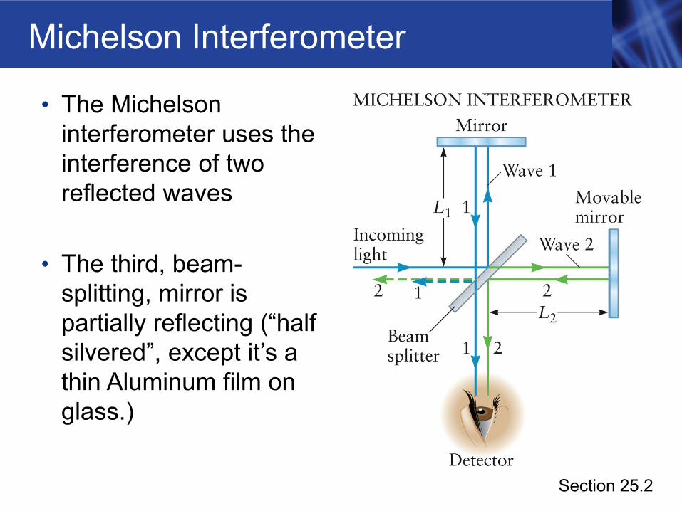
Michelson Interferometer • The Michelson interferometer uses the interference of two reflected waves • The third, beam- splitting, mirror is partially reflecting (“half silvered”, except it’s a thin Aluminum film on glass.) Section 25.2
Transcript of Michelson Interferometer - Purdue University
Michelson Interferometer
• The Michelson interferometer uses the interference of two reflected waves
• The third, beam-splitting, mirror is partially reflecting (“half silvered”, except it’s a thin Aluminum film on glass.)
Section 25.2
Michelson Interferometer, cont.
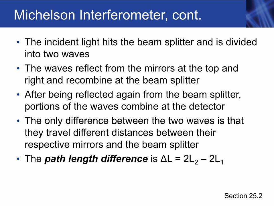
• The incident light hits the beam splitter and is divided into two waves
• The waves reflect from the mirrors at the top and right and recombine at the beam splitter
• After being reflected again from the beam splitter, portions of the waves combine at the detector
• The only difference between the two waves is that they travel different distances between their respective mirrors and the beam splitter
• The path length difference is ΔL = 2L2 – 2L1
Section 25.2
Michelson Interferometer, final
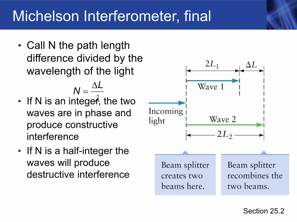
• Call N the path length difference divided by the wavelength of the light
• If N is an integer, the two waves are in phase and produce constructive interference
• If N is a half-integer the waves will produce destructive interference
LN Δ=
λ
Section 25.2
Interference Conditions
• For constructive interference, ΔL = m λ• For destructive interference, ΔL = (m + ½) λ
• Where m is an integer, 0, +-1,+-2,…..• If the interference is constructive, the light intensity
at the detector is large• Called a bright fringe
• If the interference is destructive, the light intensity at the detector is zero• Called a dark fringe
Section 25.2
Measuring Length with a Michelson Interferometer• Use the light from a laser and adjust the mirror to
give constructive interference• This corresponds to one of the bright fringes
• The mirror is then moved, changing the path length• The intensity changes from high to zero and back to
high every time the path length changes by one wavelength
• If the mirror moves through N bright fringes, the distance d traveled by the mirror is
• since 2d is the change in path length difference, D
Nd =2λ
Section 25.2
Measuring Length, cont.
• The accuracy of the measurement depends on the accuracy with which the wavelength is known
• Many laboratories use helium-neon lasers to make very precise length measurements
Section 25.2
LIGO
• LIGO – Laser Interferometer Gravitational Wave Observatory
• Designed to detect very small warping (actually stretching and shrinking of space itself!) associated with gravitational waves that arrive at the Earth from distant sources, like colliding pulsars, or colliding black holes.
• By using a long distance between the beam splitter and the mirrors, the LIGO interferometers are sensitive to exceedingly small percentage changes in that distance
Section 25.2
LIGO
• A gravity wave would stretch space in one direction and shrink it in a perpendicular direction
• For example, let each arm be 2.5 km long. Let lambda be 500 nm.
• A motion of lambda/2 shifts path difference by one fringe, or 2.5E-9 m
• As a fraction of 2.5E3 m, the accuracy would be one part in a trillion (1 E-12)
• WOW !
Section 25.2
Thin-Film Interference
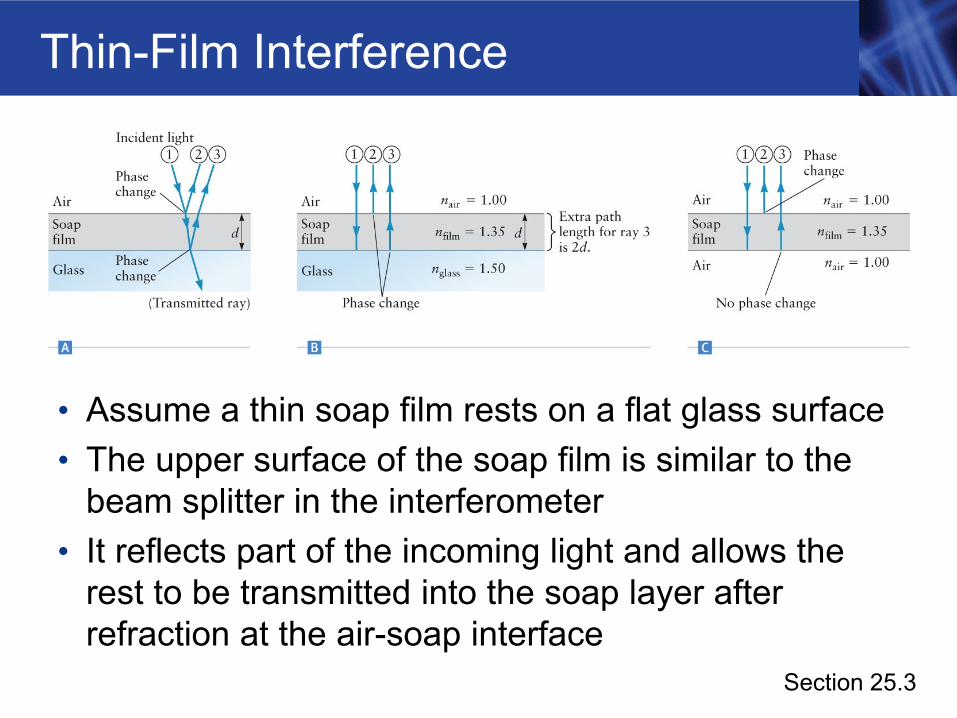
• Assume a thin soap film rests on a flat glass surface• The upper surface of the soap film is similar to the
beam splitter in the interferometer• It reflects part of the incoming light and allows the
rest to be transmitted into the soap layer after refraction at the air-soap interface
Section 25.3
Thin-Film Interference, cont.
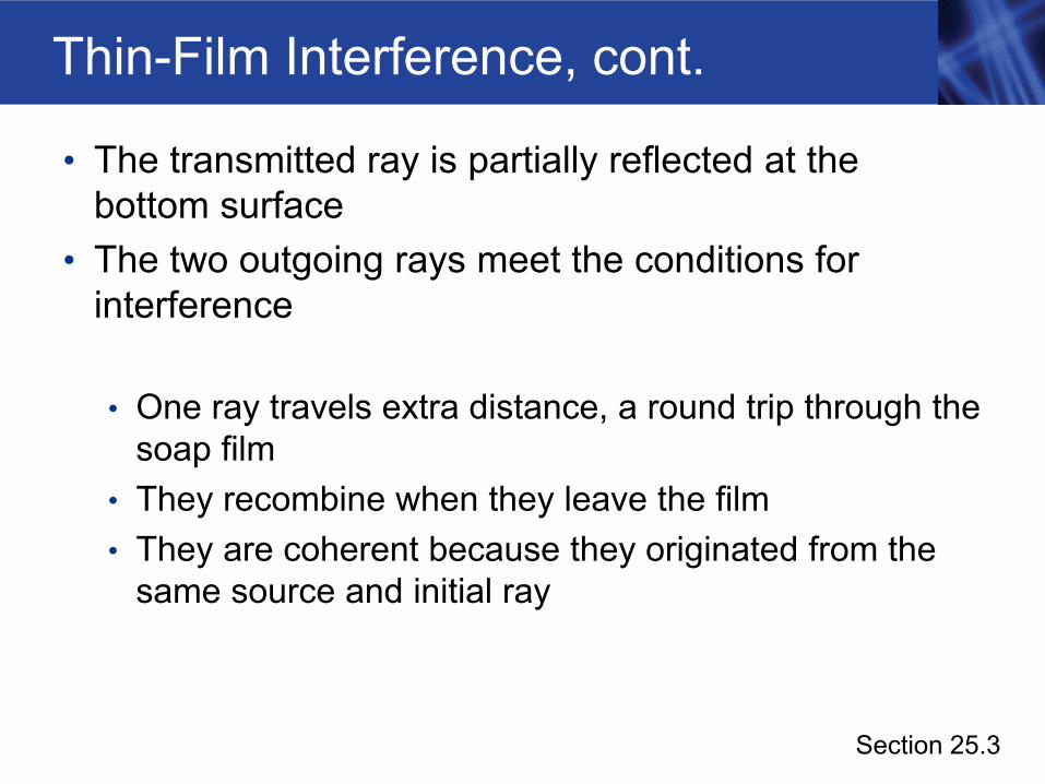
• The transmitted ray is partially reflected at the bottom surface
• The two outgoing rays meet the conditions for interference
• One ray travels extra distance, a round trip through the soap film
• They recombine when they leave the film• They are coherent because they originated from the
same source and initial ray
Section 25.3
Thin-Film Interference, final
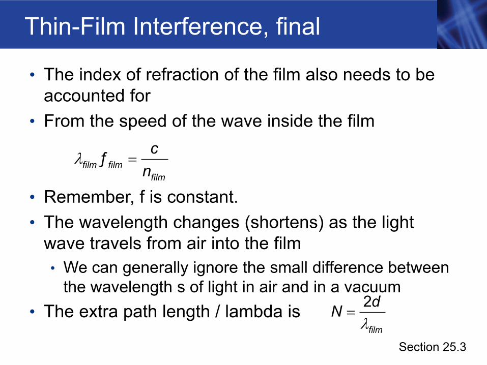
• The index of refraction of the film also needs to be accounted for
• From the speed of the wave inside the film
• Remember, f is constant.• The wavelength changes (shortens) as the light
wave travels from air into the film• We can generally ignore the small difference between
the wavelength s of light in air and in a vacuum• The extra path length / lambda is
film filmfilm
cn
=ƒλ
Section 25.3film
dN =2λ
Frequency of a Wave at an Interface
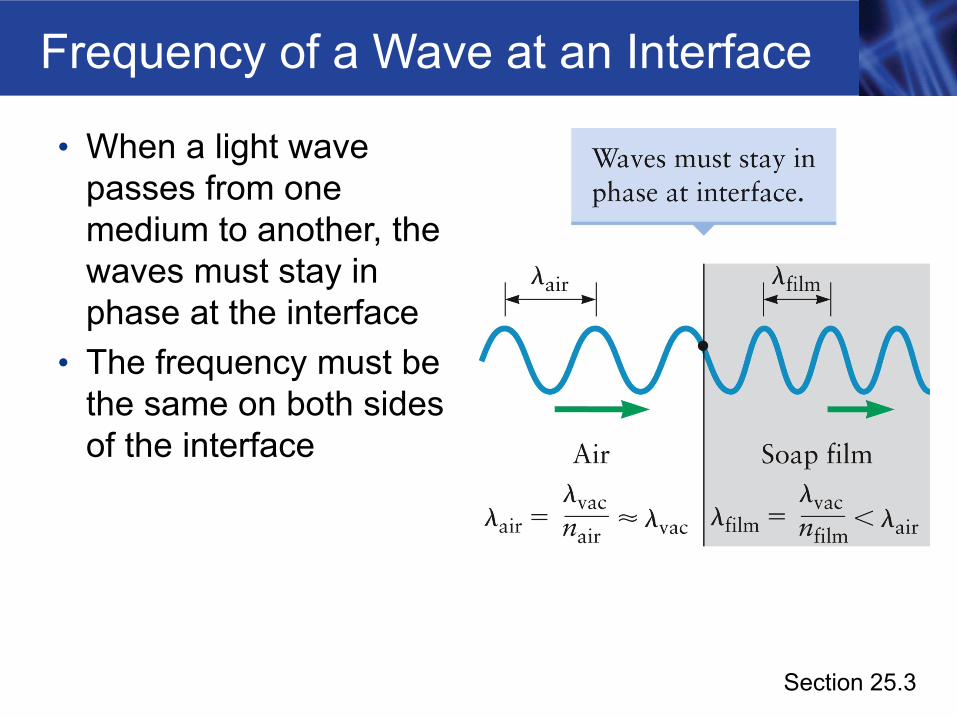
• When a light wave passes from one medium to another, the waves must stay in phase at the interface
• The frequency must be the same on both sides of the interface
Section 25.3
Phase Change and Reflection, Diagram
Section 25.3
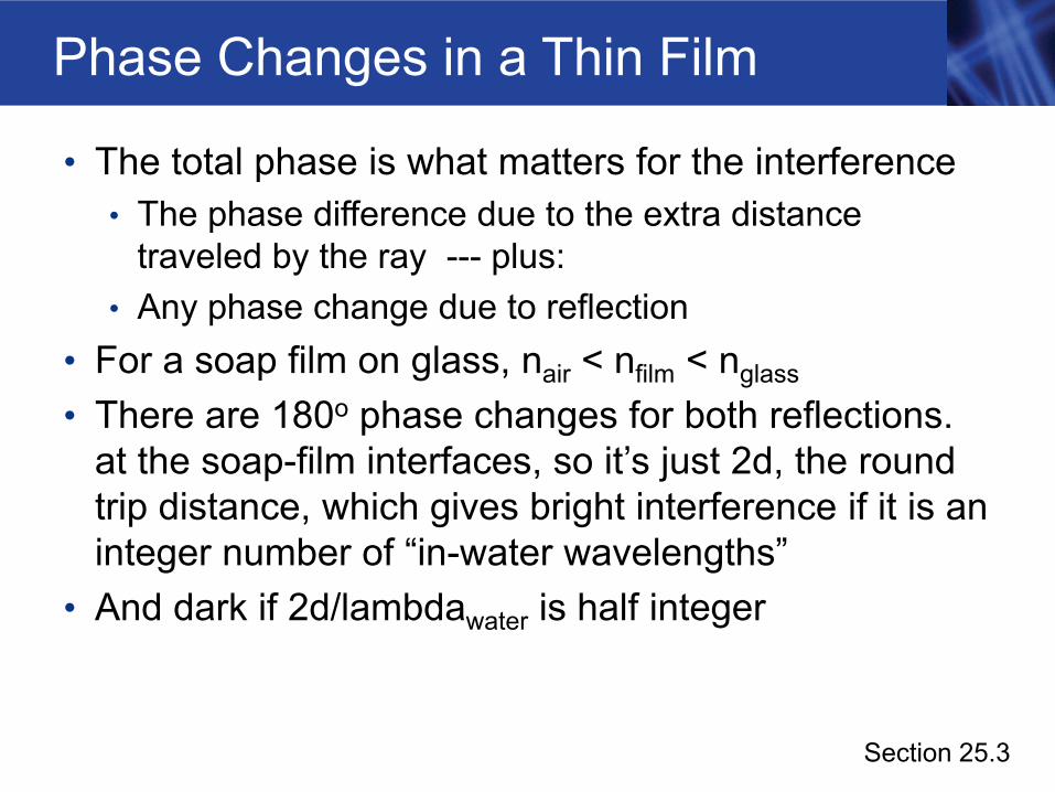
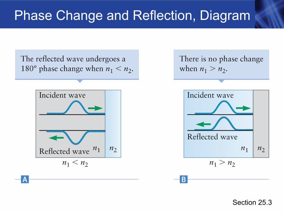
Phase Changes in a Thin Film
• The total phase is what matters for the interference• The phase difference due to the extra distance
traveled by the ray --- plus:• Any phase change due to reflection
• For a soap film on glass, nair < nfilm < nglass
• There are 180o phase changes for both reflections. at the soap-film interfaces, so it’s just 2d, the round trip distance, which gives bright interference if it is an integer number of “in-water wavelengths”
• And dark if 2d/lambdawater is half integer
Section 25.3
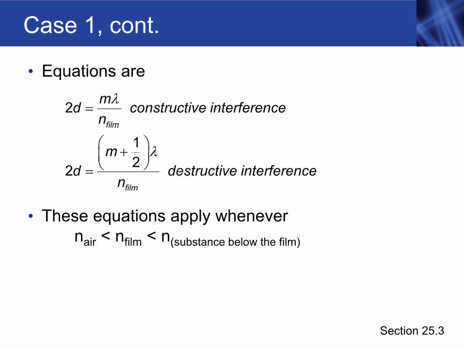
Case 1, cont.
• Equations are
• These equations apply whenever nair < nfilm < n(substance below the film)
film
film
md constructive interferencen
md destructive interference
n
=
⎛ ⎞+⎜ ⎟⎝ ⎠=
2
122
λ
λ
Section 25.3
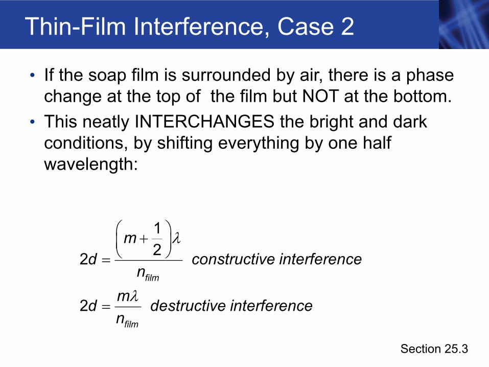
Thin-Film Interference, Case 2
• If the soap film is surrounded by air, there is a phase change at the top of the film but NOT at the bottom.
• This neatly INTERCHANGES the bright and dark conditions, by shifting everything by one half wavelength:
film
film
md constructive interference
nmd destructive interferencen
⎛ ⎞+⎜ ⎟⎝ ⎠=
=
122
2
λ
λ
Section 25.3
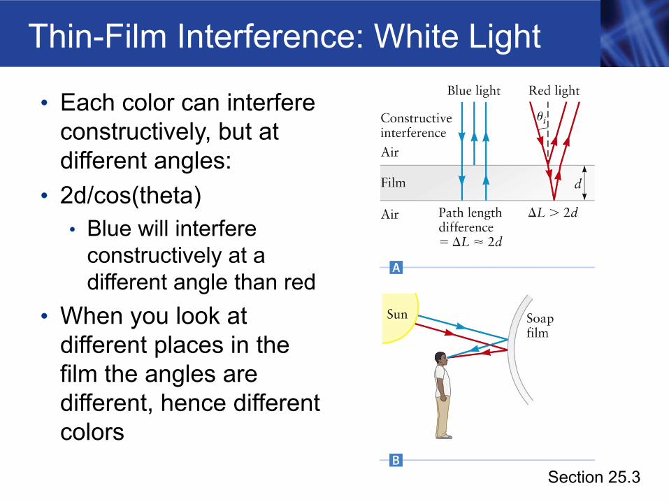
Thin-Film Interference: White Light
• Each color can interfere constructively, but at different angles:
• 2d/cos(theta)• Blue will interfere
constructively at a different angle than red
• When you look at different places in the film the angles are different, hence different colors
Section 25.3
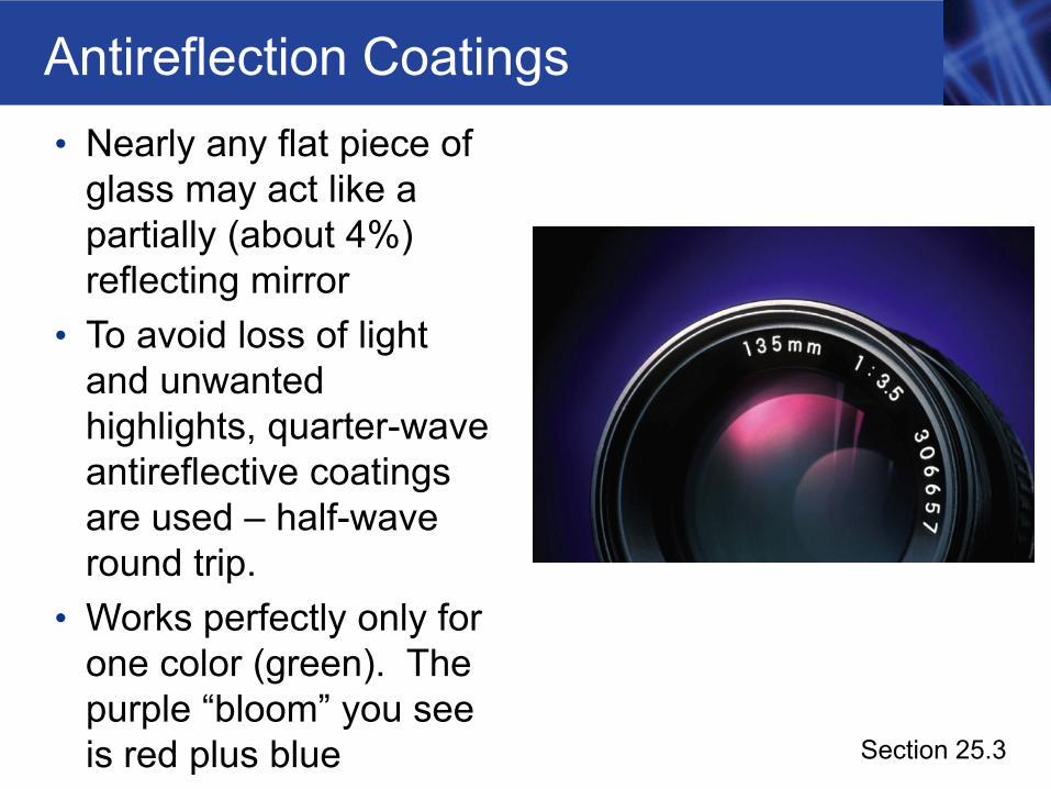
Antireflection Coatings• Nearly any flat piece of
glass may act like a partially (about 4%) reflecting mirror
• To avoid loss of light and unwanted highlights, quarter-wave antireflective coatings are used – half-wave round trip.
• Works perfectly only for one color (green). The purple “bloom” you see is red plus blue Section 25.3
Antireflective Coatings, cont.
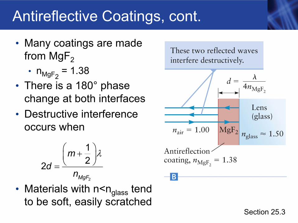
• Many coatings are made from MgF2• nMgF2
= 1.38• There is a 180° phase
change at both interfaces• Destructive interference
occurs when
• Materials with n<nglass tend to be soft, easily scratched
MgF
md
n
⎛ ⎞+⎜ ⎟⎝ ⎠=
2
122
λ
Section 25.3
Light Through a Single Slit
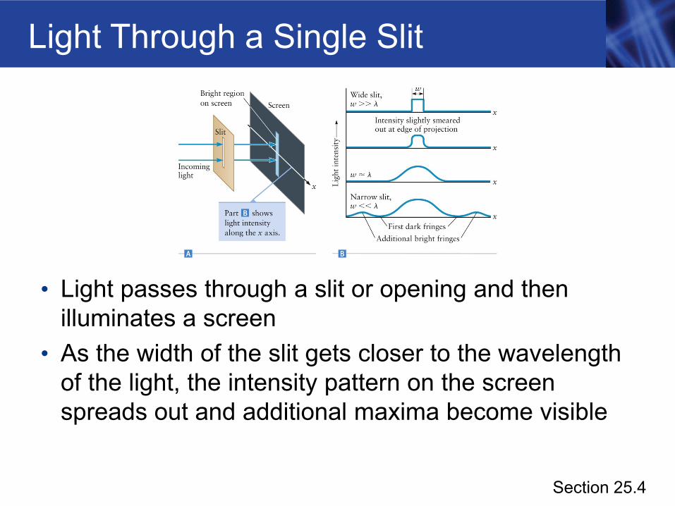
• Light passes through a slit or opening and then illuminates a screen
• As the width of the slit gets closer to the wavelength of the light, the intensity pattern on the screen spreads out and additional maxima become visible
Section 25.4
Single-Slit Diffraction
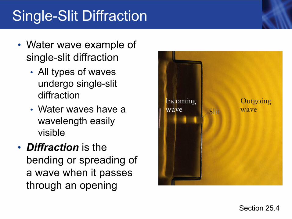
• Water wave example of single-slit diffraction• All types of waves
undergo single-slit diffraction
• Water waves have a wavelength easily visible
• Diffraction is the bending or spreading of a wave when it passes through an opening
Section 25.4
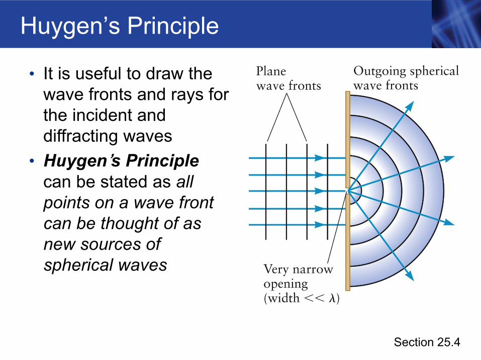
Huygen’s Principle
• It is useful to draw the wave fronts and rays for the incident and diffracting waves
• Huygen’s Principle can be stated as all points on a wave front can be thought of as new sources of spherical waves
Section 25.4
Double-Slit Interference
• Light passes through two very narrow slits• When the two slits are both very narrow, each slit
acts as a simple point source of new waves• The outgoing waves from each slit are like simple
spherical waves• The double slit experiment showed conclusively that
light is a wave• Experiment was first carried out by Thomas Young
around 1800
Section 25.5
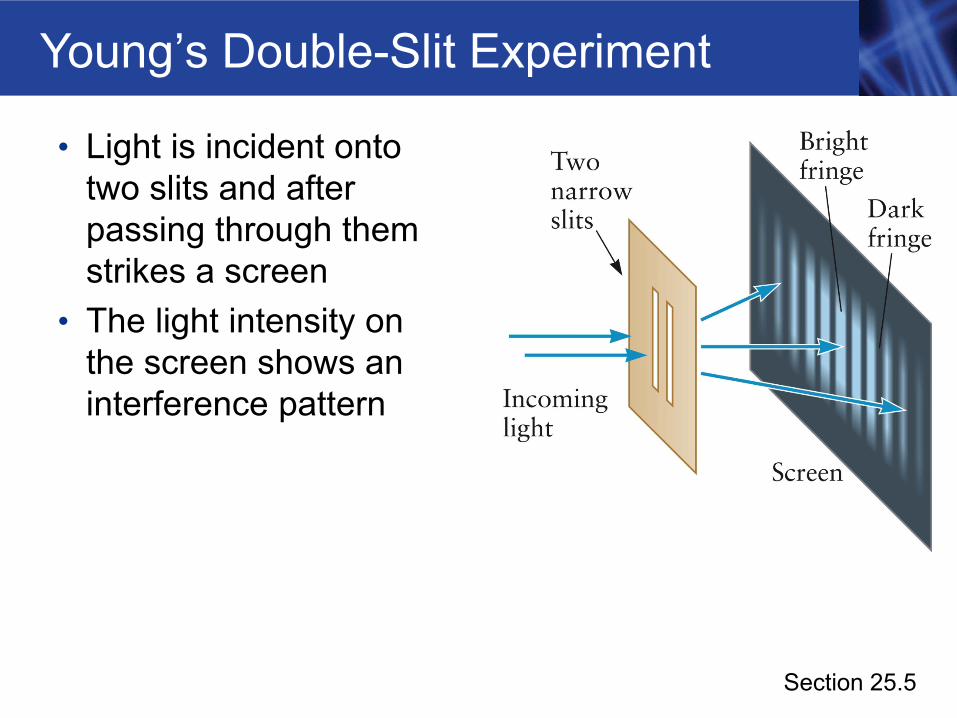
Young’s Double-Slit Experiment
• Light is incident onto two slits and after passing through them strikes a screen
• The light intensity on the screen shows an interference pattern
Section 25.5
Young’s Experiment, final
• Assume the slits are very narrow• According the Huygen’s principle, each slit acts as a
simple source with circular wave fronts as viewed from above
• The light intensity on the screen alternates between bright and dark as you move along the screen• These areas correspond to regions of constructive
interference and destructive interference
Section 25.5
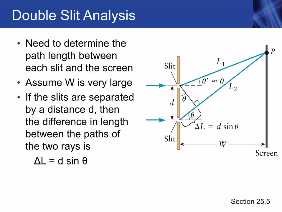
Double Slit Analysis
• Need to determine the path length between each slit and the screen
• Assume W is very large• If the slits are separated
by a distance d, then the difference in length between the paths of the two rays is ΔL = d sin θ
Section 25.5
Conditions for Interference
• For constructive interference, DL = d sin θ = m λ• m = 0, ±1, ±2, … • Will observe a bright fringe
• For destructive interference, d sin θ = (m + ½) λ• m = 0, ±1, ±2, … • Will observe a dark fringe
Section 25.5
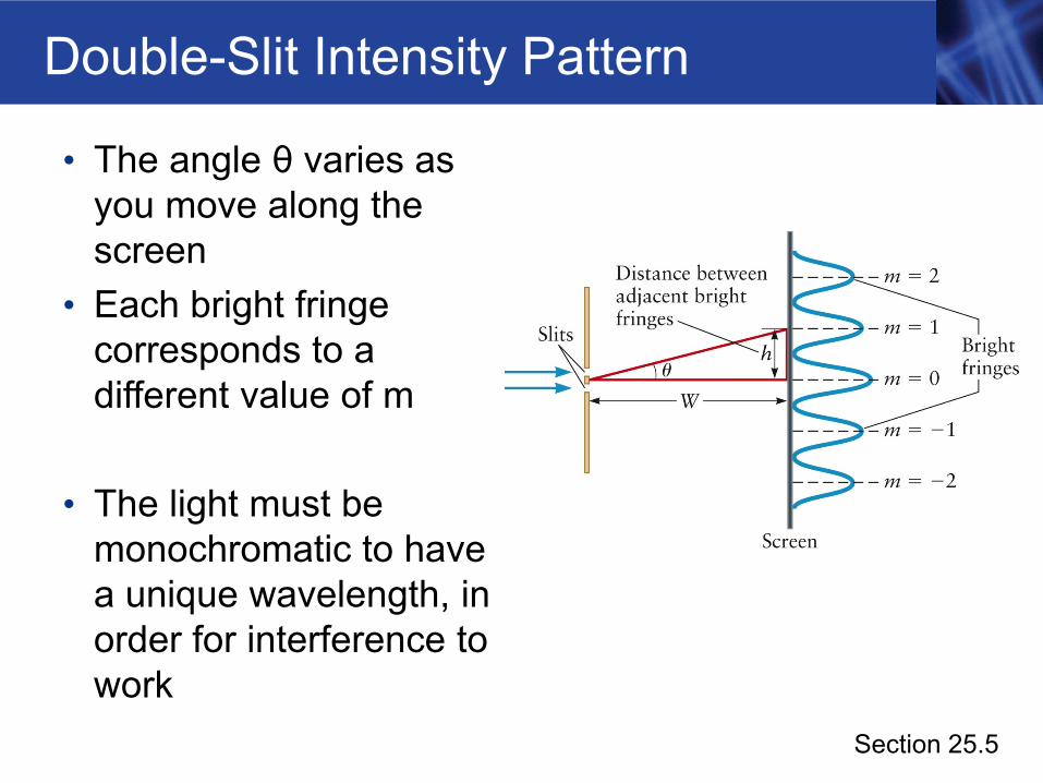
Double-Slit Intensity Pattern
• The angle θ varies as you move along the screen
• Each bright fringe corresponds to a different value of m
• The light must be monochromatic to have a unique wavelength, in order for interference to work
Section 25.5
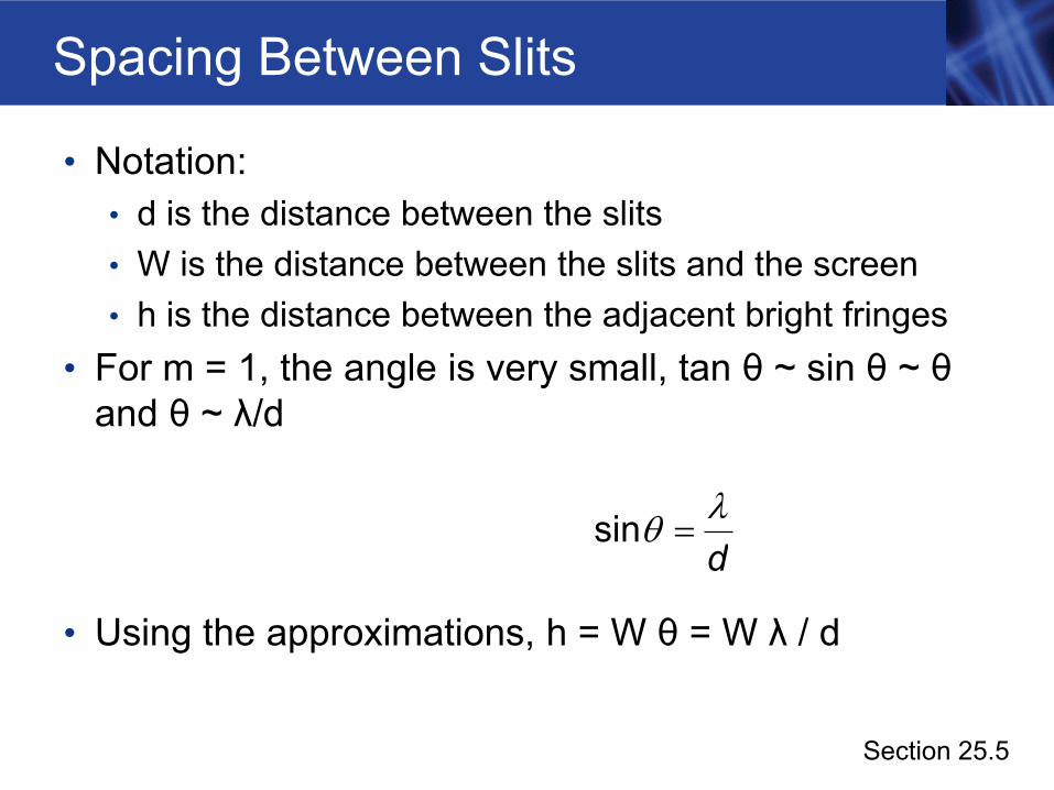
Spacing Between Slits
• Notation:• d is the distance between the slits• W is the distance between the slits and the screen• h is the distance between the adjacent bright fringes
• For m = 1, the angle is very small, tan θ ~ sin θ ~ θand θ ~ λ/d
• Using the approximations, h = W θ = W λ / d
dsin λθ =
Section 25.5
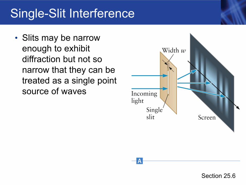
Single-Slit Interference
• Slits may be narrow enough to exhibit diffraction but not so narrow that they can be treated as a single point source of waves
Section 25.6
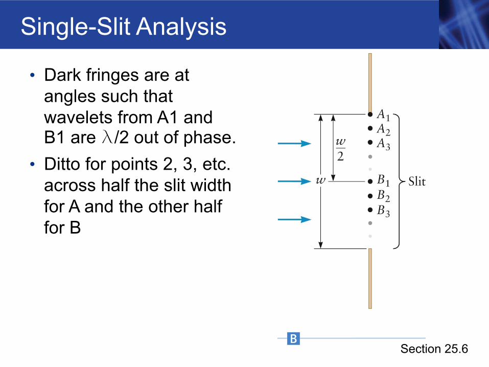
Single-Slit Analysis
• Dark fringes are at angles such that wavelets from A1 and B1 are l/2 out of phase.
• Ditto for points 2, 3, etc. across half the slit width for A and the other half for B
Section 25.6
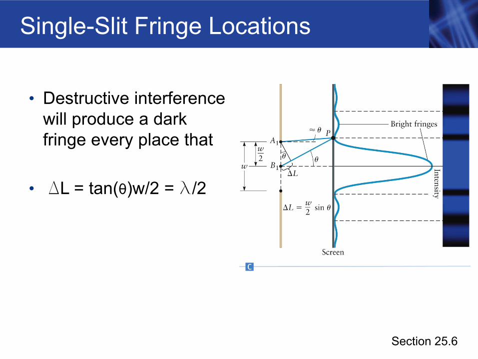
Single-Slit Fringe Locations
• Destructive interference will produce a dark fringe every place that
• DL = tan(θ)w/2 = l/2
Section 25.6
Single-Slit Analysis: Dark Fringers
• Conditions for destructive interference are w sin θ = ±m λ• m = 1, 2, 3, … • The negative sign will correspond to a fringe below the
center of the screen
Section 25.6
Single-Slit – Central Maximum
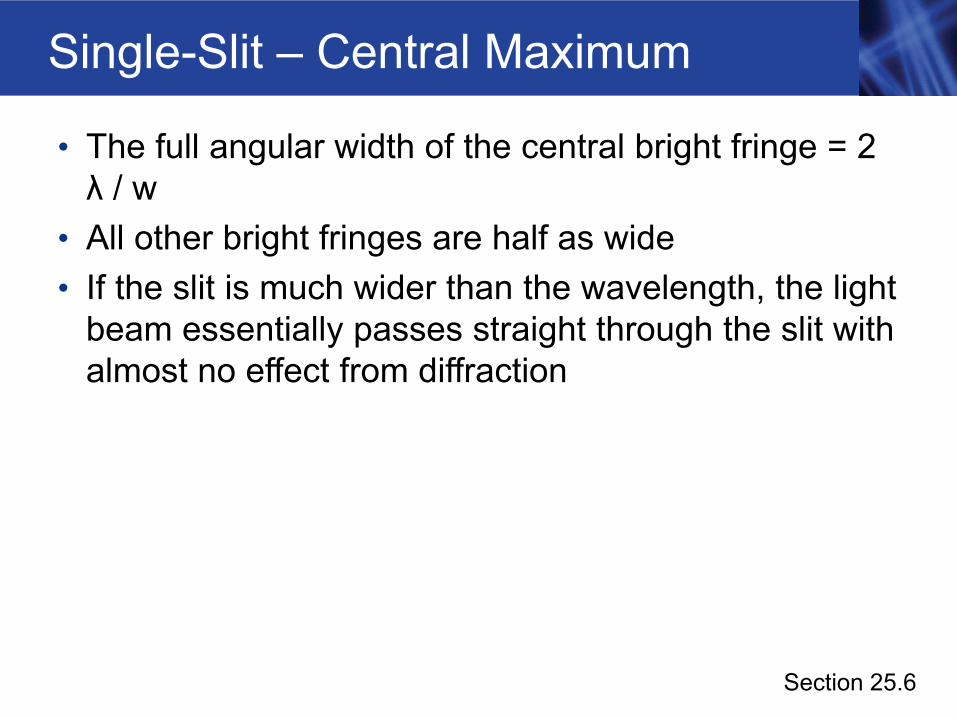
• The full angular width of the central bright fringe = 2 λ / w
• All other bright fringes are half as wide• If the slit is much wider than the wavelength, the light
beam essentially passes straight through the slit with almost no effect from diffraction
Section 25.6
Diffraction Grating
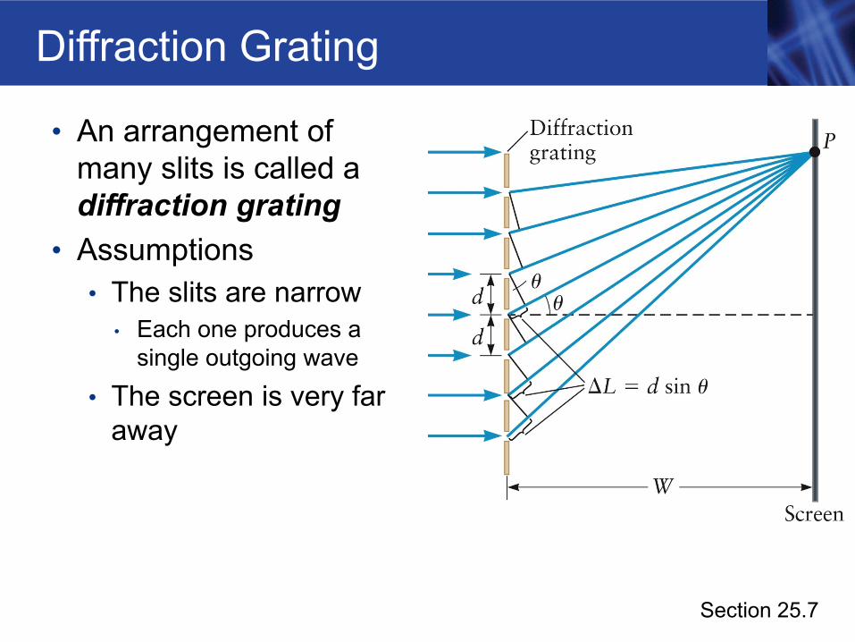
• An arrangement of many slits is called a diffraction grating
• Assumptions• The slits are narrow
• Each one produces a single outgoing wave
• The screen is very far away
Section 25.7
Diffraction Grating, cont.
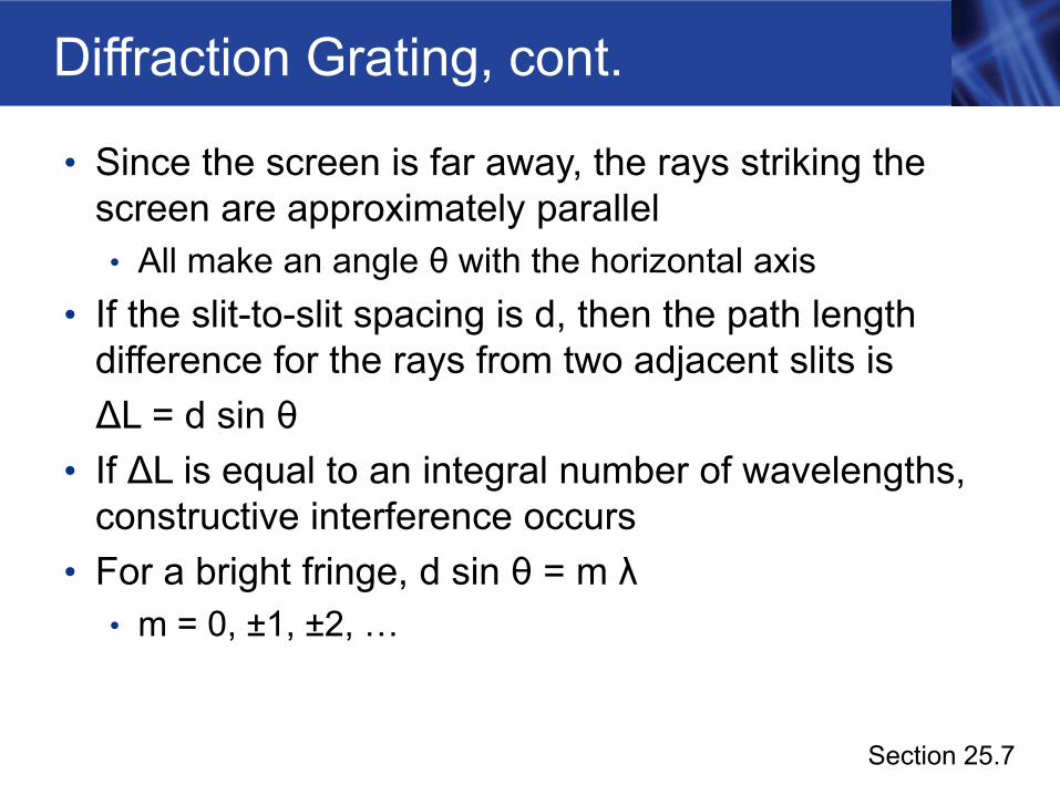
• Since the screen is far away, the rays striking the screen are approximately parallel• All make an angle θ with the horizontal axis
• If the slit-to-slit spacing is d, then the path length difference for the rays from two adjacent slits isΔL = d sin θ
• If ΔL is equal to an integral number of wavelengths, constructive interference occurs
• For a bright fringe, d sin θ = m λ• m = 0, ±1, ±2, …
Section 25.7
Diffraction Grating, final
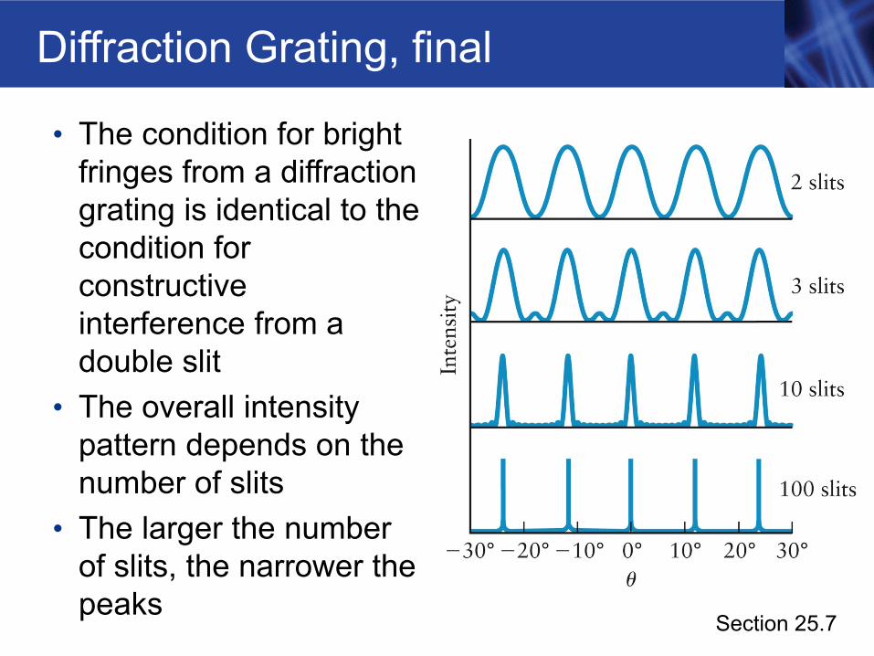
• The condition for bright fringes from a diffraction grating is identical to the condition for constructive interference from a double slit
• The overall intensity pattern depends on the number of slits
• The larger the number of slits, the narrower the peaks
Section 25.7
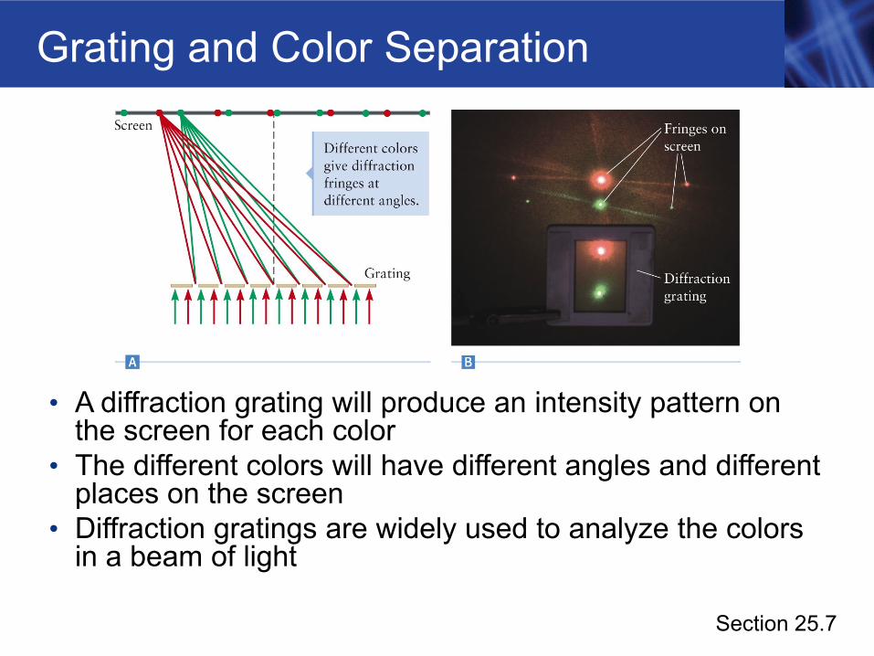
Grating and Color Separation
• A diffraction grating will produce an intensity pattern on the screen for each color
• The different colors will have different angles and different places on the screen
• Diffraction gratings are widely used to analyze the colors in a beam of light
Section 25.7
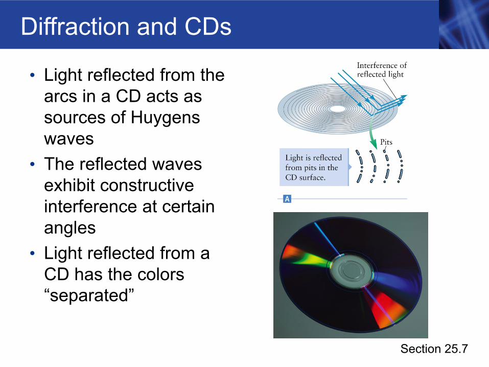
Diffraction and CDs
• Light reflected from the arcs in a CD acts as sources of Huygens waves
• The reflected waves exhibit constructive interference at certain angles
• Light reflected from a CD has the colors “separated”
Section 25.7
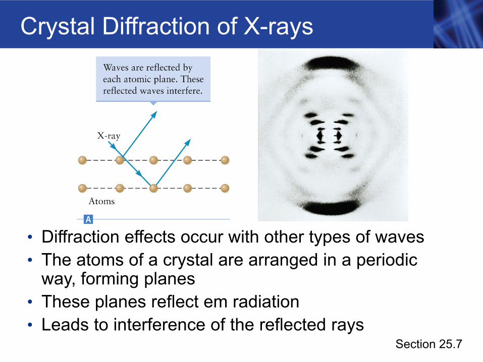
Crystal Diffraction of X-rays
• Diffraction effects occur with other types of waves• The atoms of a crystal are arranged in a periodic
way, forming planes • These planes reflect em radiation• Leads to interference of the reflected rays
Section 25.7
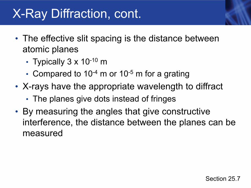
X-Ray Diffraction, cont.
• The effective slit spacing is the distance between atomic planes• Typically 3 x 10⁻¹⁰ m• Compared to 10-4 m or 10-5 m for a grating
• X-rays have the appropriate wavelength to diffract• The planes give dots instead of fringes
• By measuring the angles that give constructive interference, the distance between the planes can be measured
Section 25.7
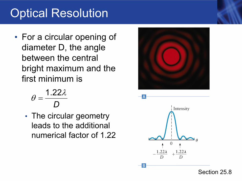
Optical Resolution
• For a circular opening of diameter D, the angle between the central bright maximum and the first minimum is
• The circular geometry leads to the additional numerical factor of 1.22
D1.22λθ =
Section 25.8
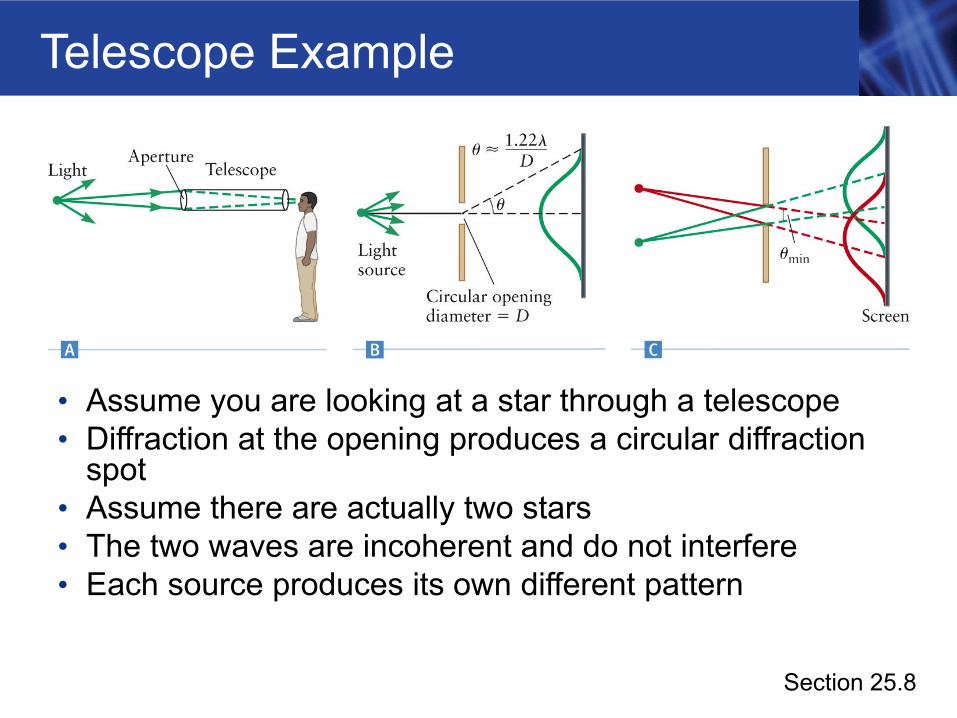
Telescope Example
• Assume you are looking at a star through a telescope• Diffraction at the opening produces a circular diffraction
spot• Assume there are actually two stars• The two waves are incoherent and do not interfere• Each source produces its own different pattern
Section 25.8
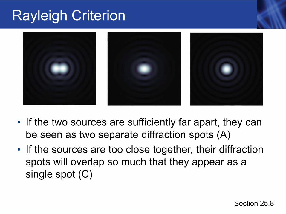
Rayleigh Criterion
• If the two sources are sufficiently far apart, they can be seen as two separate diffraction spots (A)
• If the sources are too close together, their diffraction spots will overlap so much that they appear as a single spot (C)
Section 25.8
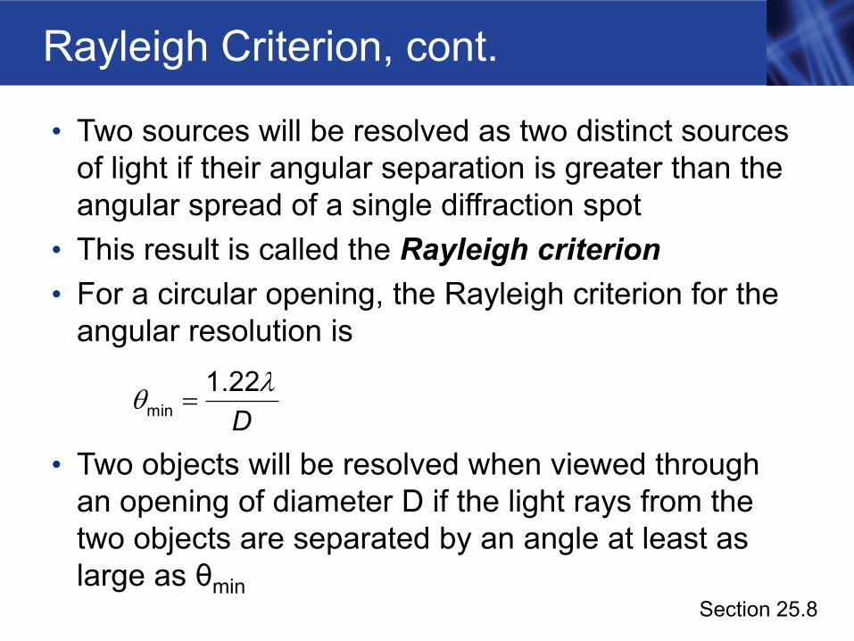
Rayleigh Criterion, cont.
• Two sources will be resolved as two distinct sources of light if their angular separation is greater than the angular spread of a single diffraction spot
• This result is called the Rayleigh criterion• For a circular opening, the Rayleigh criterion for the
angular resolution is
• Two objects will be resolved when viewed through an opening of diameter D if the light rays from the two objects are separated by an angle at least as large as θmin
Dmin1.22λθ =
Section 25.8
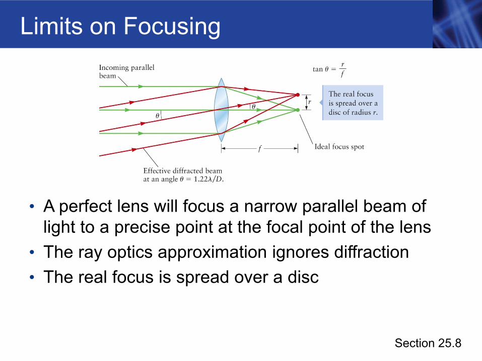
Limits on Focusing
• A perfect lens will focus a narrow parallel beam of light to a precise point at the focal point of the lens
• The ray optics approximation ignores diffraction• The real focus is spread over a disc
Section 25.8
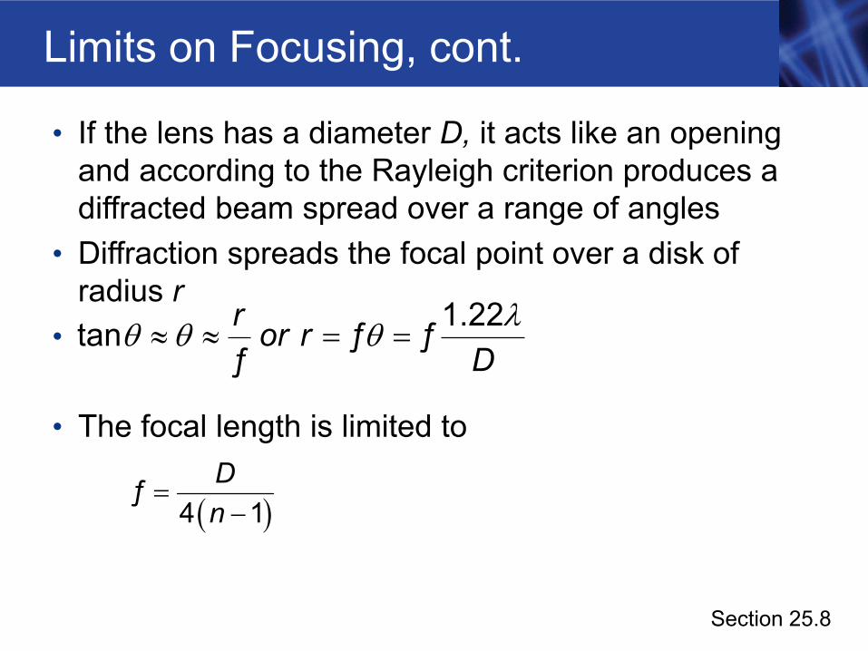
Limits on Focusing, cont.
• If the lens has a diameter D, it acts like an opening and according to the Rayleigh criterion produces a diffracted beam spread over a range of angles
• Diffraction spreads the focal point over a disk of radius r
•
• The focal length is limited to
r or rD
1.22tan ƒ ƒƒ
λθ θ θ≈ ≈ = =
( )Dn
=−
ƒ4 1
Section 25.8
Limits on Focusing, final
• The wave nature of light limits the focusing qualities of even a perfect lens
• It is not possible to focus a beam of light to a spot smaller than approximately the wavelength
• The ray approximation of geometrical optics can be applied at size scale much greater than the wavelength
• When a slit or a focused beam of light is made so small that its dimensions are comparable to the wavelength, diffraction effects become important
Section 25.8
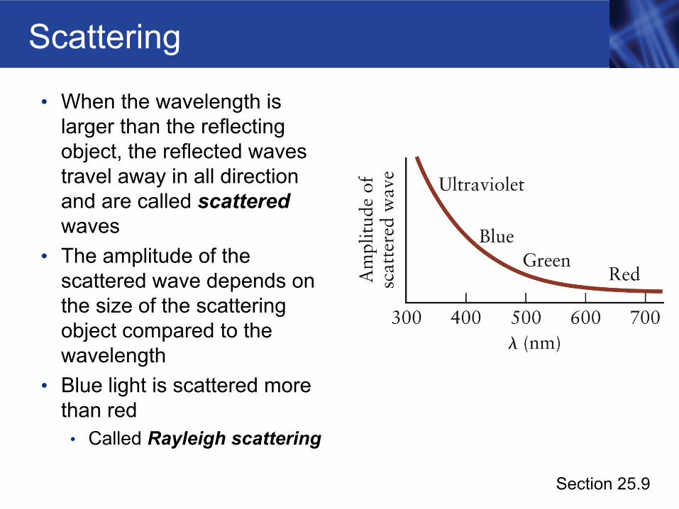
Scattering
• When the wavelength is larger than the reflecting object, the reflected waves travel away in all direction and are called scatteredwaves
• The amplitude of the scattered wave depends on the size of the scattering object compared to the wavelength
• Blue light is scattered more than red
• Called Rayleigh scattering
Section 25.9
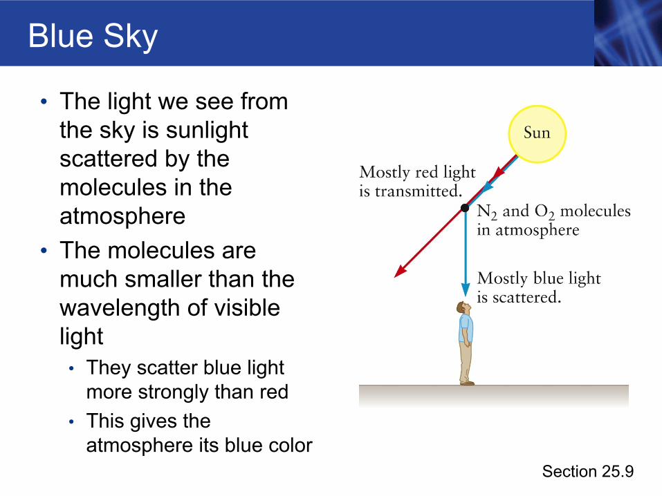
Blue Sky
• The light we see from the sky is sunlight scattered by the molecules in the atmosphere
• The molecules are much smaller than the wavelength of visible light• They scatter blue light
more strongly than red• This gives the
atmosphere its blue colorSection 25.9
Scattering, Sky, and Sun
• Blue sky• Although violet scatters more than blue, the sky
appears blue• The Sun emits more strongly in blue than violet• Our eyes are more sensitive to blue• The sky appears blue even though the violet light is
scattered more• Sun near horizon
• There are more molecules to scatter the light• Most of the blue is scattered away, leaving the red
Section 25.9
Nature of Light
• Interference and diffraction show convincingly that light has wave properties
• Certain properties of light can only be explained with a particle theory of light• Color vision is one effect that can be correctly
explained by the particle theory• Have strong evidence that light is both a particle and
a wave• Called wave-particle duality• Quantum theory tries to reconcile these ideas
Section 25.10
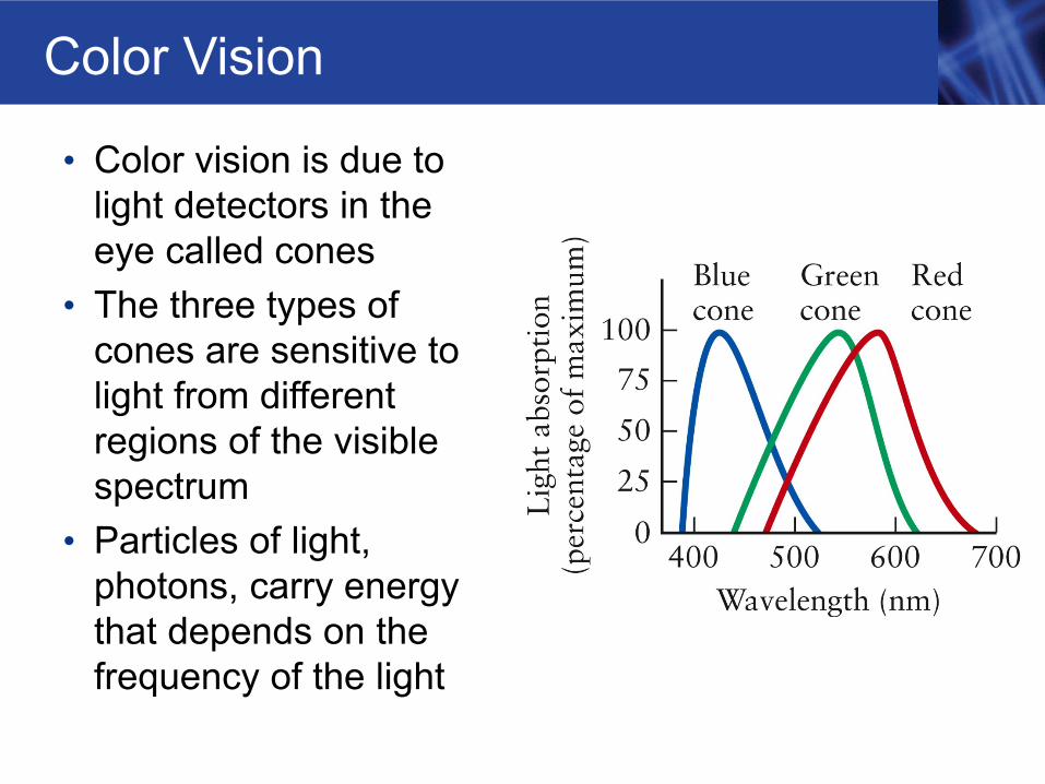
Color Vision
• Color vision is due to light detectors in the eye called cones
• The three types of cones are sensitive to light from different regions of the visible spectrum
• Particles of light, photons, carry energy that depends on the frequency of the light