LEOI-22 Precision Interferometer Instruction...
25
LEOI-22 Precision Interferometer Instruction Manual Lambda Scientific Pty Ltd 6A Hender Avenue, Magill, South Australia 5072, Australia Phone: +61 8 8333 0382 Facsimile: +61 8 8333 0380 E-mail: [email protected] Web: www.lambdasci.com COPYRIGHT V2-0
-
Upload
nguyenminh -
Category
Documents
-
view
224 -
download
0
Transcript of LEOI-22 Precision Interferometer Instruction...

LEOI-22 Precision Interferometer
Instruction Manual
Lambda Scientific Pty Ltd
6A Hender Avenue, Magill, South Australia 5072, Australia Phone: +61 8 8333 0382 Facsimile: +61 8 8333 0380
E-mail: [email protected] Web: www.lambdasci.com
COPYRIGHT V2-0

COMPANY PROFILE
Lambda Scientific specializes in developing and manufacturing various
spectrophotometers, spectroscopic instruments, thin film measurement, physics education
kits, optical components, opto-mechanic parts, and light sources. Spectrophotometer
products include infrared spectrophotometer and ultraviolet-visible spectrophotometers.
Our spectroscopic instruments include laser Raman spectrometer, multifunctional grating
spectrographs, multi-channel optical analysers and monochromators, whose detectors are
PMT, single photon counter or CCD, etc. They are either manual or computer-controlled.
Physics experimental instruments and education kits cover wide range of experimental
projects in general physics, especially in geometrical, physical and modern optics, e.g. lens
measurements, interference phenomena, diffraction phenomena, analysis of polarization,
Fourier optics and holography etc. We also provide a variety of optical components,
optical mounts and optical breadboards. Light sources include xenon lamps, mercury
lamps, sodium lamps, bromine tungsten lamps and various lasers. Our products have been
sold around the world. Lambda Scientific is committed to providing high quality, cost
effective products and on-time delivery.
CONTENTS 1. Introduction ................................................................................................................................ 1
2. Specifications ............................................................................................................................. 1
3. Theory ........................................................................................................................................ 1
3.1 Interference ........................................................................................................................... 1
3.2 Michelson Interferometer...................................................................................................... 2
3.3 Fabry-Perot Interferometer ................................................................................................... 4
3.4 Twyman-Green Interferometer ............................................................................................. 4
4. Structure ..................................................................................................................................... 6
5. Operation of Experiment Examples ........................................................................................... 7
5.1 Michelson Interferometer...................................................................................................... 7
5.1.1 Interference Fringes Observation ................................................................................... 7
5.1.2 Equal Inclination Interference........................................................................................ 9
5.1.3 Equal Thickness Interference ....................................................................................... 10
5.1.4 White Light Interference Fringes ................................................................................. 10
5.1.5 Measurement of Wavelength of the Sodium D-lines ................................................... 12
5.1.6 Measurement of the Wavelength Separation of Sodium D-lines ................................. 13
5.1.7 The Refractive Index of Air ......................................................................................... 13
5.1.8 The Refractive Index of Transparency Slice ............................................................... 15
5.2 Fabry-Perot Interferometer ................................................................................................. 16
5.2.1 The Multi-beam Interference ....................................................................................... 16
5.2.2 Measurement of the Wavelength of He-Ne Laser ....................................................... 17
5.2.3 Observation of the Interference of Sodium D-lines ..................................................... 18
5.3 Twyman-Green Interferometer ........................................................................................... 19
5.3.1 Demonstrating the principle of a Twyman-Green interferometer ............................... 19
6. Maintenance ............................................................................................................................. 21
6.1 Optical components ............................................................................................................ 21
6.2 Driving mechanism ............................................................................................................. 21
7. Laser safety and lab requirements ............................................................................................ 21
8. Parts List ................................................................................................................................... 22

1
1. Introduction
The Michelson interferometer can be used for observing interference phenomena such as equal
inclination interference, equal thickness interference, white-light interference, precision
wavelength contrast, determine the zero-path difference and measuring refractive index of a
transparent medium slice or air. The Fabry-Perot interferometer is used for observing multiple-
beam interference and measuring the fine structure of spectra (e.g. wavelength disparity of
yellow sodium doublet lines). Twyman-Green interferometer is used to measure the defects of
optical components such as lenses, prisms and windows etc.
This equipment can be easily switched between the Michelson, Fabry-Perot and Twyman-
Green Interferometers. Its application is to optical experiments in physics teaching at
universities and other tertiary institutions.
2. Specifications
Flatness of Beam Splitter and Compensator Plate 0.1λ
Minimum travel reading 0.00025mm
Travel of moving mirror 0.625mm (travel of fine micrometer: 25mm)
Sodium-tungsten lamp Sodium: 10W; Tungsten:15W
He-Ne laser output 0.7 ~ [email protected]
Overall dimension 350mm×350mm×245mm
Weight Approx. 15 Kg
3. Theory
3.1 Interference
Light has two vectors: an electric field vector and a magnetic field vector, and these two
vectors can be used to model light waves. When two or more beams of light meet in space,
these fields add according to the principle of superposition.
Generally, light beams which originate from separate sources have no fixed relationship. At
any instant there will be points in space where the fields add to produce the maximum field
strength. Because there is no fixed relationship between the oscillations, a point where there is
a maximum at one instant may have a minimum at the next. As the oscillations of visible light
are faster than the human eye can perceive, the human eye averages these results and perceives
a uniform intensity of light.
If the light beams come from the same source, there is generally some degree of correlation
between the frequency and phase of the oscillations. At one point in space the light from the
beams may always be in phase. So the combined field will always be a maximum and a bright
spot will be seen. At another point the light from the beams may be always out of phase and
minima, or dark spot, will be seen. This phenomenon is called interference.

2
In 1801, Thomas Young designed a method for producing such an interference pattern. He
allowed a single, narrow beam of light to fall on two narrow, closely spaced slits, and placed a
viewing screen opposite the slits. When the light from the two slits overlapped on the screen, a
regular pattern of dark and bright bands appeared. When first performed, Young’s experiment
offered important evidence to the wave nature of light.
Young’s slits can be used as a simple interferometer. If the spacing between the slits is known,
the spacing of the maxima and minima can be used to determine the wavelength of the light.
Conversely, if the wavelength of the light is known, the spacing of the slits could be
determined from the interference pattern.
3.2 Michelson Interferometer
In 1881, A. A. Michelson designed and built an interferometer using a similar principle.
Originally Michelson designed his interferometer as a means to test for the existence of the
ether, a hypothesized medium in which light was thought to propagate. Due in part to his
efforts, the ether is no longer considered a viable hypothesis. However, Michelson’s
interferometer has become a widely used instrument for measuring the wavelength of light, for
measuring extremely small distances by using a light source with the known wavelength, and
for investigating optical media.
E
BS CP M2
M1
M2'
S
The above figure shows a schematic diagram of a Michelson interferometer. The beam of light
from the light source S strikes the beam-splitter BS, which reflects 50% of the incident light
and transmits the other 50%. The incident beam is therefore split into two beams; one beam is
reflected toward the fixed mirror M1, the other is transmitted toward the movable mirror M2.
Both mirrors reflect the light directly back toward the beam-splitter BS. The light from M1 is
transmitted through the beam-splitter BS to the observer’s eye E, and the other light from M2 is
transmitted through the compensator plate CP and reflected from the beam-splitter BS to the
observer’s eye E.
Since the beams are from the same light source, their phases are highly correlated. When a
beam expander is placed between the light source and the beam-splitter, the light rays spread
out, and an interference pattern of dark and bright rings, or fringes, can be seen by the observer.
In above figure, M2’ is the virtual image of M2, and the light path of the Michelson
interferometer can be seen as the light path of the air plate between M1 and M2’. The

3
compensator plate CP parallel to the beam splitter BS has the same thickness and refractive
index with the BS. Because the light paths of the two beams are equal, and different light
waves have the same retardation, and it is easy for observing the white-light interference.
The forming process of the interference rings is shown in the following figure.
2d
d
E
L
PM1 M2'θL2L1
P''P'
P' P'' θ2d
2dcosθ
M2’ is the virtual image of M2, and parallel to M1. For simplicity, light source L is at the
observer’s position. L1 and L2 are the virtual images of L formed by M1 and M2’, and are
coherent. Let d be the distance between M1 and M2’, therefore the distance between L1 and L2
is 2d. So, if d = mλ/2 (m is an integer), the phases of the light beams from the normal direction
of L1 and L2 are the same, but the phases of the light beams from other direction are not always
the same. Light beams from the points P’ and P” to the observer have a path difference 2dcosθ.
If M1 is parallel to M2’, the two light beams have the same angle, θ, and are parallel to each
other. So, when 2dcosθ = nλ (n is an integer), the two light beams form a maximum field
strength. For definite n, λ and d, the value of θ is a constant, and the contour of the maximum
point becomes a ring. The centre of the ring is at the bottom in the line of viewing being
perpendicular to the mirror plane.
4
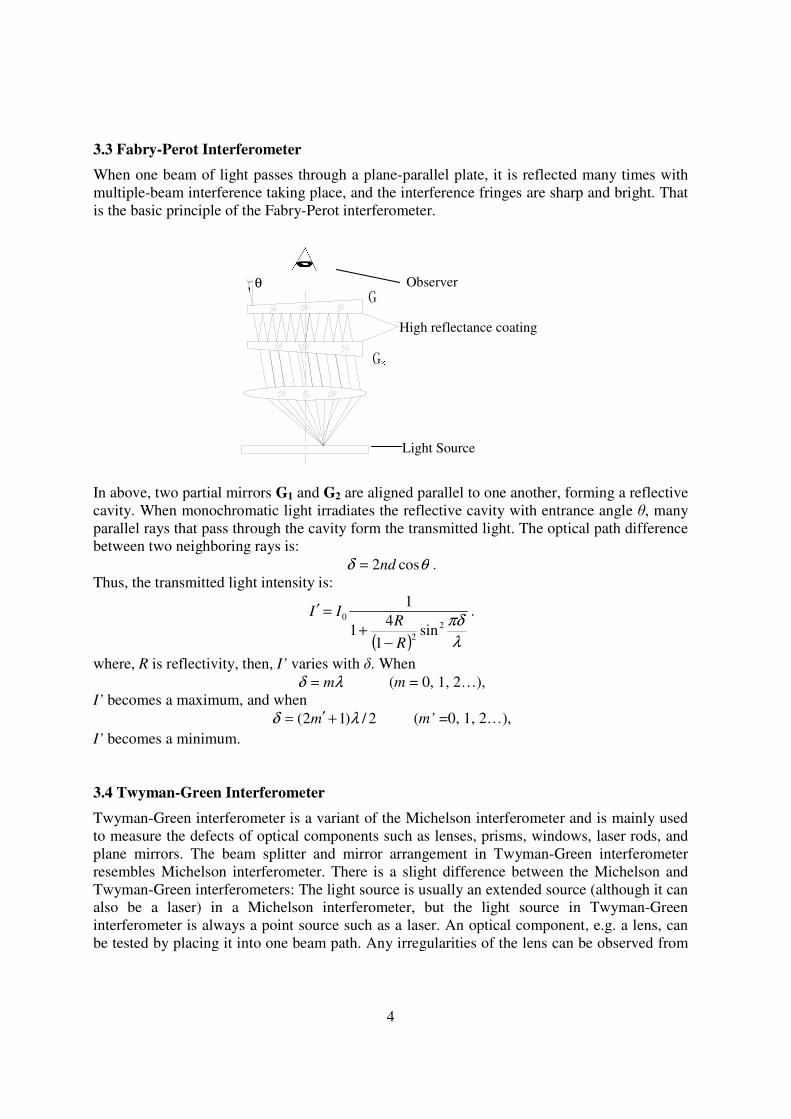
3.3 Fabry-Perot Interferometer
When one beam of light passes through a plane-parallel plate, it is reflected many times with
multiple-beam interference taking place, and the interference fringes are sharp and bright. That
is the basic principle of the Fabry-Perot interferometer.
G1 G2
Light Source
High reflectance coating
Observer θ
In above, two partial mirrors G1 and G2 are aligned parallel to one another, forming a reflective
cavity. When monochromatic light irradiates the reflective cavity with entrance angle θ, many
parallel rays that pass through the cavity form the transmitted light. The optical path difference
between two neighboring rays is:
θδ cos2nd= .
Thus, the transmitted light intensity is:
( ) λ
πδ2
2
0
sin1
41
1
R
RII
−+
=′ .
where, R is reflectivity, then, I’ varies with δ. When
λδ m= (m = 0, 1, 2…),
I’ becomes a maximum, and when
2/)12( λδ +′= m (m’ =0, 1, 2…),
I’ becomes a minimum.
3.4 Twyman-Green Interferometer
Twyman-Green interferometer is a variant of the Michelson interferometer and is mainly used
to measure the defects of optical components such as lenses, prisms, windows, laser rods, and
plane mirrors. The beam splitter and mirror arrangement in Twyman-Green interferometer
resembles Michelson interferometer. There is a slight difference between the Michelson and
Twyman-Green interferometers: The light source is usually an extended source (although it can
also be a laser) in a Michelson interferometer, but the light source in Twyman-Green
interferometer is always a point source such as a laser. An optical component, e.g. a lens, can
be tested by placing it into one beam path. Any irregularities of the lens can be observed from

5
the resulting interference pattern. In particular, spherical aberration, coma, and astigmatism
show up as specific variations in the fringe pattern.
M2
M1
W1
W2
Sample
B C
L2
L1
Screen
S A
BS
In above figure, if the sample has perfectly flat surfaces, the returning wave front is plane and
no fringes are observed. However, if the optical flat is not perfectly flat on either side, the wave
from M2 returning to the beam splitter is no longer plane. Thus, the phase difference between
the superimposed waves of M1 and M2 will vary across the field of view and a fringe pattern
appears. These fringes are a contour map of the distorted wave front, so that the imperfections
of the sample are displayed in terms of wave front aberrations.

6
4. Structure
This equipment combines a Michelson interferometer, a Fabry-Perot interferometer and a
Twyman-Green interferometer on one square base, which is made of thick steel plate and has a
stable rigid-frame.
10
0 105
0
45
40
5
1. Main stage 10. Fine micrometer
2. Side stage 11. Movable mirror
3. Light source (He-Ne laser or sodium-tungsten lamp) 12. Stage with mounting holes for 6 and 8
4. Beam expander 13. Compensator
5. Transparency slice clamp 14. Beam splitter
6. Ground glass screen 15. Extension arm
7. Rotational pointer and SOCKET3 16. Two in one screen
8. Fixed Mirror (It is also used as a F-P mirror) 17. SOCKET2 for beam expander
9. Presetting micrometer
The structure of the equipment is shown in Figure 4-1. On the side stage 2, there is one
extruded hole for installing light sources (He-Ne laser or sodium-tungsten lamp) and three
small holes for holding other items such as beam expander (4), transparency slice clamp (5)
and ground glass screen (6). Beam expander is installed in SOCKET2 (17) when in use. Fixed
mirror (8) is both the reference mirror of Michelson interferometer and used as the front mirror
of Fabry-Perot interferometer. Beam splitter (14) is plated semi permeable film on the inner
side. Compensator (13) has the same thickness as beam splitter (14) and is at 90° angle to (14).
The relative position of beam splitter and compensator has been adjusted before leaving the
factory and there should be no need for adjustment. Movable mirror (11) is controlled by fine
micrometer (10) which has a travel of 25mm. When the fine micrometer moves a distance of
0.01mm (resolution), movable mirror moves a distance of 0.00025mm with respect to main
stage. A ground glass screen (13) is used to receive the fringes of the Michelson interferometer,
and for protecting the eye from the laser light.
7
5. Operation of Experiment Examples
5.1 Michelson Interferometer
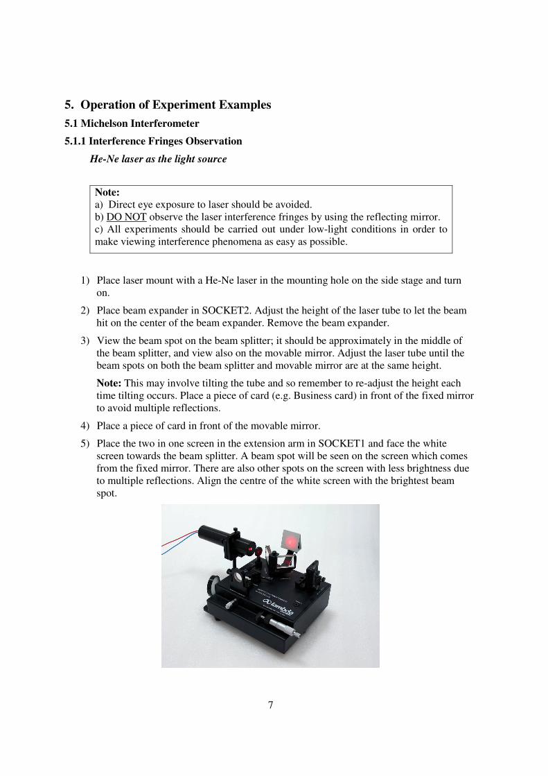
5.1.1 Interference Fringes Observation
He-Ne laser as the light source
Note:
a) Direct eye exposure to laser should be avoided.
b) DO NOT observe the laser interference fringes by using the reflecting mirror.
c) All experiments should be carried out under low-light conditions in order to
make viewing interference phenomena as easy as possible.
1) Place laser mount with a He-Ne laser in the mounting hole on the side stage and turn
on.
2) Place beam expander in SOCKET2. Adjust the height of the laser tube to let the beam
hit on the center of the beam expander. Remove the beam expander.
3) View the beam spot on the beam splitter; it should be approximately in the middle of
the beam splitter, and view also on the movable mirror. Adjust the laser tube until the
beam spots on both the beam splitter and movable mirror are at the same height.
Note: This may involve tilting the tube and so remember to re-adjust the height each
time tilting occurs. Place a piece of card (e.g. Business card) in front of the fixed mirror
to avoid multiple reflections.
4) Place a piece of card in front of the movable mirror.
5) Place the two in one screen in the extension arm in SOCKET1 and face the white
screen towards the beam splitter. A beam spot will be seen on the screen which comes
from the fixed mirror. There are also other spots on the screen with less brightness due
to multiple reflections. Align the centre of the white screen with the brightest beam
spot.

8
6) Remove the piece of card and view the white screen. Two bright spots should appear
(and less bright multiple reflections). Adjust the movable mirror until the two bright
spots coincide with each other at the centre of the white screen.
7) Position the beam expander into SOCKET2 with the lens lock facing the beam splitter.
If the expanded beam spot is not immediately incident on the movable mirror then
adjust the laser tube. The fringe pattern can be observed on the white screen.
Note: When adjusting the expanded beam spot, it may not be immediately obvious in
some cases. Hold a piece of paper behind the movable mirror to identify the location of
the beam spot. Adjust the two tilting screws on the laser holder to move the spot onto
the movable mirror.
If you achieve fringes but they are not circular and smaller as you may expect then make some
adjustments to the presetting micrometer to ‘zoom’ in or out to get a better view. If you did not
achieve fringes, closely follow the instructions from the beginning; otherwise contact
[email protected] for technical support.
Using sodium lamp as the source
1) Take away the He-Ne laser and beam expander. Place sodium lamp in the mounting
hole.
2) Flip the two in one screen to view the interference pattern on the mirror. Adjust the
height of the lamp, so that the sodium light strikes at the center of the mirror.
Commonly, Interference fringes can be observed from the reflected light.
Note: If you can not find any fringes, it means that the interference light path has
changed by the vibrations when you replaced the light source. To get back the fringes
we should do as the following processes.
3) Place a pinhole board (you can pierce a hole on a business card by a pin) on front of the
lamp and adjust the movable mirror until the two images of the pinhole coincide with
each other.

9
4) Remove the pinhole board and interference fringes will be observed by viewing the
mirror. Using the ground glass screen is optional in this experiment but if it is preferred
insert the ground glass in between the light source and the beam splitter (SOCKET2).
5.1.2 Equal Inclination Interference
Now let’s study the different kinds of fringes which are produced by Michelson interferometer.
As shown in the following picture,
Figure 5-3: Illustration of Equal Inclination Interference
M2’ is the virtual image of movable mirror M2. In the observer’s field of view, it looks like that
the two light beams are reflected from mirror M1 and M2’ and the interference pattern is just
like the thin air film between M1 and M2’.
He-Ne laser as the light source
1) Re-produce the interference image as per 5.1.1 which should be similar to (a).
2) Adjust the coarse micrometer such that images (a) to (e) are viewed in succession.
3) Set the fine micrometer to the middle of the scale (between 10mm to15mm).
4) Re-adjust the coarse micrometer as close as possible to image (c).
5) Use the fine micrometer to produce fringes of equal inclination.

10
5.1.3 Equal Thickness Interference
Figure 5-4: Fringes of equal thickness
Adjust the screws at the back of M2 and if M1 and M2’ has a very small angle with each other,
the fringes of equal thickness interference can be observed on the screen.
He-Ne laser as the light source
1) Install the He-Ne laser and remove the beam expander. Turn the fine micrometer to the
middle of the scale (between 10mm to15mm).
2) Adjust the laser and movable mirror to get interference pattern on the white screen.
3) Turn the coarse micrometer in the direction which interference rings disappeared at
their center, and the fringes will grow larger. Stop when there are only a few fringes on
the screen.
4) Turn the fine micrometer to move the movable mirror in the direction which
interference rings disappeared at their center, until there are only two or three rings left.
5) Adjust the movable mirror a little. If the image of movable mirror M2’ is tilted relative
to the fixed mirror M1, you will see the interference stripes.
6) Continue turn the fine micrometer to make the curved fringes move toward their center.
Some straight bands will appear in succession. That is the fringes of equal thickness.
5.1.4 White Light Interference Fringes
Because white light has a short coherence length, interference fringes can only be observed
when the optical path difference is nearly zero. Compared with the interference pattern created
by a laser or a Sodium lamp, obtaining white light interference is much more difficult. With the
help of a specially designed Sodium-Tungsten lamp, you may quickly find the point of zero
path difference.

11
1) After achieving equal inclination interference (5.1.2), replace the laser with a sodium-
tungsten lamp and remove the beam expander. Use the mirror of the two in one screen
as the observation screen.
2) Adjust the height of the light source until the yellow sodium
light and white tungsten light illuminate the upper and lower
half of the visual field respectively. Make sure that the visible
sodium fringes have good contrast and wide-spacing.
Interference fringes of sodium doublet may help you to locate
the point of zero path difference.
If you do not see any fringes, it means that the interference
light path has changed by the vibrations when you replaced
the light source. To get back the fringes we should do as the
following processes.
3) Place a pinhole board (you can pierce a hole on a business card by a pin) on front of the
lamp and adjust the movable mirror until the two images of the pinhole coincide with
each other, and then you will get interference fringes in the viewing mirror.
4) Search for white light fringes by turning the fine micrometer slowly and alter the path
length at such a rate that you can always see the yellow fringes traversing the field of
view. In this way you will be able to approach zero path difference at maximum speed
but will not miss the appearance of the white light fringes.
5) When color fringes gradually appear, a central dark interference fringe can be
identified. That is the interference at the position of zero light-path difference.
6) To observe the white light interference fringe clearly, you can turn off the Sodium lamp
and put the ground glass screen in SOCKET2.

12
5.1.5 Measurement of Wavelength of the Sodium D-lines
1) Place the sodium-tungsten lamp on the side-stage of the interferometer and warm it up
for about 5 minutes.
2) Adjust the interferometer to produce circular fringes in the field of view.
3) At the position with a clear equal inclination fringes, record the reading d0 of the fine
micrometer.
4) Count the number of fringes that appear (or disappear) in the center of the field of view
as the fine micrometer is turned slowly. After counting 50 fringes, record the
micrometer reading again
5) Continue above process through 250 fringes, recording the micrometer reading after
each set of 50 fringes has been counted. Calculate the ∆d. The actual mirror
movement, d∆ , is equal to λN∆ /2, where λ is the wavelength of the source.
The moving distance is:
2
λNd
∆=∆
And ∆N is the number rings counted. So,
N
d
∆
∆=
2λ
Notice:
a) Always turn the micrometer knob in one direction.
b) Set the micrometer screw somewhere near the middle of its total movement. In this
position, the relationship between the micrometer reading and the mirror movement is
most nearly linear.
c) Turn the micrometer screw a full turn before counting fringes to eliminate errors due to
backlash.
13
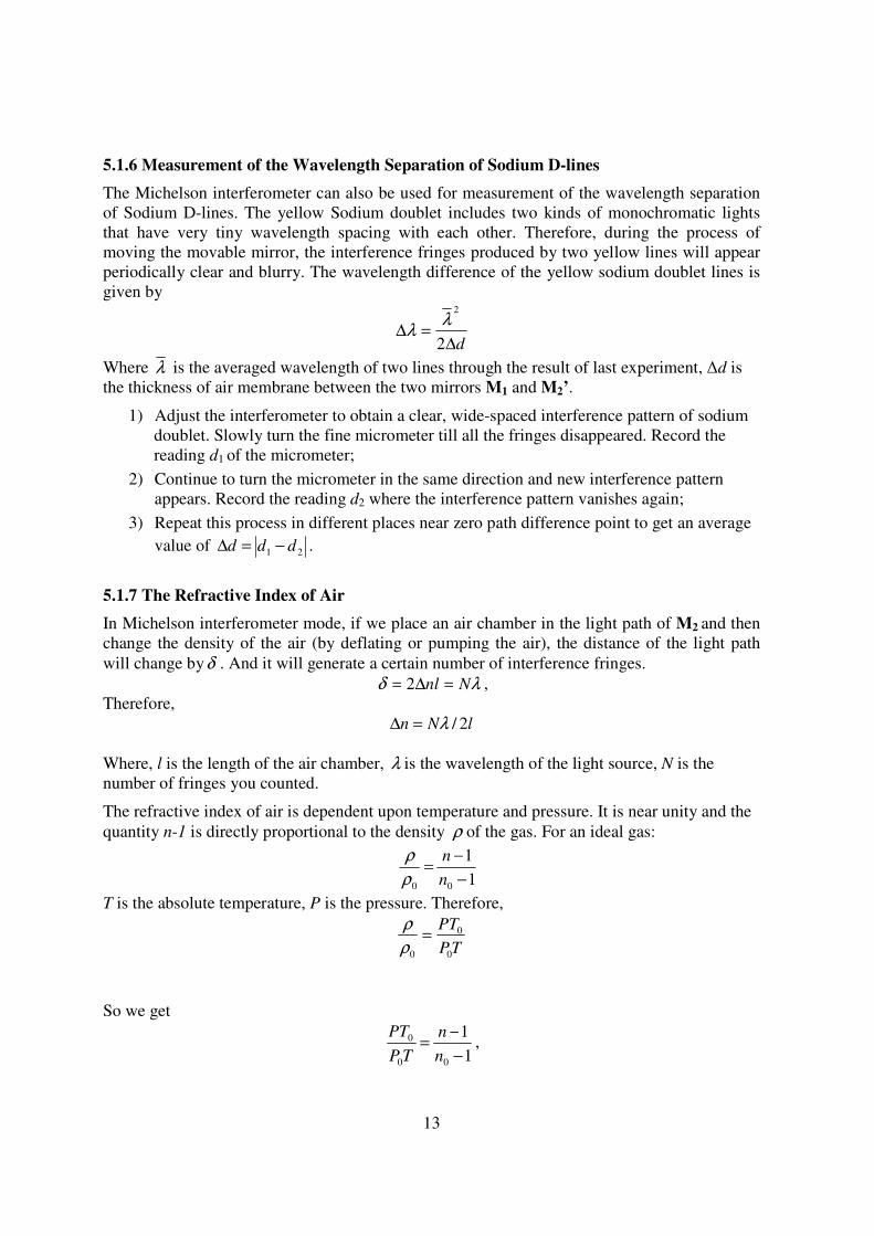
5.1.6 Measurement of the Wavelength Separation of Sodium D-lines
The Michelson interferometer can also be used for measurement of the wavelength separation
of Sodium D-lines. The yellow Sodium doublet includes two kinds of monochromatic lights
that have very tiny wavelength spacing with each other. Therefore, during the process of
moving the movable mirror, the interference fringes produced by two yellow lines will appear
periodically clear and blurry. The wavelength difference of the yellow sodium doublet lines is
given by
d∆=∆
2
2
λλ
Where λ is the averaged wavelength of two lines through the result of last experiment, ∆d is
the thickness of air membrane between the two mirrors M1 and M2’.
1) Adjust the interferometer to obtain a clear, wide-spaced interference pattern of sodium
doublet. Slowly turn the fine micrometer till all the fringes disappeared. Record the
reading d1 of the micrometer;
2) Continue to turn the micrometer in the same direction and new interference pattern
appears. Record the reading d2 where the interference pattern vanishes again;
3) Repeat this process in different places near zero path difference point to get an average
value of 21 ddd −=∆ .
5.1.7 The Refractive Index of Air
In Michelson interferometer mode, if we place an air chamber in the light path of M2 and then
change the density of the air (by deflating or pumping the air), the distance of the light path
will change byδ . And it will generate a certain number of interference fringes.
λδ Nnl =∆= 2 ,
Therefore,
lNn 2/λ=∆
Where, l is the length of the air chamber, λ is the wavelength of the light source, N is the
number of fringes you counted.
The refractive index of air is dependent upon temperature and pressure. It is near unity and the
quantity n-1 is directly proportional to the density ρ of the gas. For an ideal gas:
1
1
00 −
−=
n
n
ρ
ρ
T is the absolute temperature, P is the pressure. Therefore,
TP
PT
0
0
0
=ρ
ρ
So we get
1
1
00
0
−
−=
n
n
TP
PT,

14
When temperature is constant, then
PTP
Tnn ∆
−=∆
0
00 )1(
Because lNn 2/λ=∆ , we have
lNPTP
Tn2/
)1(
0
00 λ=∆−
So
P
P
l
Nn
∆×+=
21
λ
1) Align the equipment.
2) Adjust the movable mirror M2 to get clear fringes of equal inclination on the centre of
white screen using the He Ne Laser.
3) Put the air chamber with known length l in its holder (for accurate measurement, the
end plates of the air chamber must be perpendicular to the laser beam);
4) Pump in air to the chamber; record the reading of the gauge P∆ .
5) Release the valve and slowly deflate the air in the chamber till the pointer on the gauge
is back to 0. While you do this, count N. The refractive index of air in the experiment
environment is
P
P
l
Nn
∆×+=
21
λ
Note: This experiment should be carried out several times in order to get the average.
Notice: To protect the gauge, the reading of the gauge should not be over 40Kpa

15
5.1.8 The Refractive Index of Transparency Slice
When place a transparency slice in one optical arm of the Michelson interferometer, light path
of this arm will changes as the transparency slice is rotating. The difference of the light path
can be determined by counting the number of the fringes disappeared or appeared. And the
light path has a relation to the rotating angleθ , the thickness d and the refractive index n of
the slice.
If the entrance light is perpendicular to the transparency slice at first, and after rotating a
angleθ , the change of the number of fringes is N . The refractive index n is given by:
λθ
θ
Ndn
dnn
−−=
)cos1(2
sin
0
22
0
Where λ is the wavelength of the light source (the He-Ne laser), 0n is the refractive index of
air.
Experiment Procedures
1) Place the transparency slice clip in the mounting hole in SOCKET3.
2) Place the two in one screen on the extension arm and adjust the screws at the back of
the movable mirror to get a set of clear fringes on the white screen.
3) Mount the transparency slice on the clip. Adjust the clip and the rotational pointer and
make sure that the slice is approximately perpendicular to the optical path.
4) Rotate the clip using the pointer slowly and observe the fringes on the screen carefully
at the same time. The fringes in the center of the screen will disappear or appear. Until
at a position that the fringes do not disappear or appear, stop rotating. Now the slice
should now be perpendicular to the optical path.
5) Adjust the movable mirror to get a set of clear fringes on the screen. Slowly rotate the
slice by moving the lever arm. Count the number of fringe transitions that occur as you
rotate the slice from its current angle to its new angle (at least 10 degrees). If the
rotating angle isθ , and the number of fringes emission is N then we can get the
refractive index n by the equation:

16
λθ
θ
Ndn
dnn
−−=
)cos1(2
sin
0
22
0
Where 0n = the index of refraction of air (see Experiment above), λ = the wavelength
of He-Ne laser in vacuum, and N = the number of fringe transitions that you counted.
d = the thickness of the transparency slice (d = 0.1mm).
6) Repeat the last three processes 4, 5 and 6 three times and calculate the average of n.
5.2 Fabry-Perot Interferometer
5.2.1 The Multi-beam Interference
1) Turn the interferometer 90° to make the Fabry-Perot interferometer facing to the
observer who is at the position opposite to the movable mirror (see structure figure
in chapter 4).
2) Unscrew the F-P (fixed) mirror, and then mount it in the holes in front of the
movable mirror. Make sure that the surface of F-P mirror is faced towards the
movable mirror.
3) Adjust the three screws behind the movable mirror to make sure that the two mirrors
are parallel to each other approximately and the distance between them is about 2
mm.
4) Unscrew the screw on the top of the beam splitter and compensator and remove it.
Put it in a safe place (Fixing it in the place of fixed mirror is a good choice).
5) Set up the He-Ne laser at the light path of Fabry-Perot interferometer. Adjust the
laser to let the beam hit on the center of the F-P mirror. Adjust the top and right
screws behind the movable mirror to let the beam spots coincident. It means the two
mirrors are near parallel.
6) Place a beam expander and a ground glass screen into the light path to create area
light source, so that the observer can find a series of multi-beam interference rings.
To make it simple, as shown in above figure, you can also find the multi-beam fringes. If the
G1 and G2 are absolutely parallel to each other, the interference fringes on the ground glass
screen will look like a perfect circle (you should mount it in the extension arm, see dotted lines
in structure in chapter 4).
EyeG2G1Ground
Glass
Screen Beam
Expander He-Ne Laser

17
5.2.2 Measurement of the Wavelength of He-Ne Laser
The interference fringes of F-P interferometer are clearer and thinner than in Michelson’s. So if
we use the method of counting the rings to measure the wavelength of He-Ne laser, the result
will be more exact than Michelson interferometer.
1) Setup the F-P interferometer.
2) Adjust the interferometer carefully to produce clear circular fringes in the center of
ground glass screen.
3) At this time, record the reading d0 of the fine micrometer.
4) Count the number of fringes that appear (or disappear) in the center of the ground glass
screen as the micrometer is turned slowly. After counting 50 fringes, record the
micrometer reading again
6) Calculate the ∆d. The actual mirror movement d∆ is equal to λN∆ /2, where λ is the
wavelength of the source. ∆N is the number of rings we counted, here ∆N=50.
The moving distance is:
2
λNd
∆=∆
And ∆N is the number rings counted. So,
N
d
∆
∆=
2λ
7) To avoid any errors in counting the rings or recording the reading of the micrometer,
steps 1- 6 should be repeated at least 3 times.
Eye
G2G 1 Ground
Glass
Screen
Beam ExpanderHe-Ne Laser

18
5.2.3 Observation of the Interference of Sodium D-lines
The low pressure Sodium lamp is used as the light source. The light emitted by the Sodium
lamp actually has two different wavelengths which produces two different sets of concentric
interference fringes on the ground glass screen.
When rotating the fine micrometer, the observer can find that the two sets of interference
fringes will coincide at certain positions and separate at other positions.
1) Setup the instrument in F-P mode. Use the sodium lamp as the light source and turn
on the power.
2) Slowly move the movable mirror by adjusting the screws behind it till they are very
close to each other. The distance between them is about 1-2mm. (Notice: Do not let
them touch each other).
3) Place a pinhole plate in front of the lamp. Generally, the light beam through a hole in
front the lamp forms a series of light spots due to the reflections of the two mirrors
or it may look like a comets tail. Adjust the movable mirrors in order to make those
spots or tail coincide.
4) Move away the pinhole plate and adjust the movable mirror carefully till you get
clear interference fringes. For the convenience of observation, the ground glass
screen can be used in the mounting hole in front of F-P mirror (Fixed Mirror), as
shown in the above figure.
5) Slowly rotating the fine micrometer to observe the Separating- Coincidence-
Separating phenomena of the interference fringes.
Note: Be careful when adjusting the screws of the movable mirror to avoid the collision of the two mirrors.
S
Ground
Glass
Screen G1 G2

19
5.3 Twyman-Green Interferometer
5.3.1 Demonstrating the principle of a Twyman-Green interferometer
Twyman-Green interferometer is used to check optics by parallel light. Following figures are
the familiar checking modes of it.
a) Check flat mirror
M1
Test Mirror
L1
Screen
S
BS
M2
The figure shows the structure of checking flat mirror. If the test mirror has any defects, the
corresponding fringes can be observed on the screen.
b) Check transparent flat optic
M2
M1
Flat
L1
Screen
S
BS
The figure shows the structure of transparent flat optic. If the flat optic has any defects, the
corresponding fringes can be observed on the screen.
c) Check prism
M2
M1
Prism
L1
Screen
S
BS

20
The figure shows the sketch map of checking prism.
d) Check lens
M1
Lens
L1
Screen
S
BS
Perfect Spherical
Mirror
The figure shows the sketch map of checking lens.
Notice:
This instrument is design to demo the checking principle of Twyman-Green
interferometer and can not be used to check optics. Here we use mode b), and with the
help of expand light source (laser and beam expander) to demo the principle.
Experiment Procedures
1) Set up the instrument according to the Michelson interferometer. He-Ne laser is used
as the light source.
2) Adjust the movable mirror to get equal thickness fringes on the screen. Refer the
particular procedures in experiment 5.1.3.
3) Place the thin film (Sample 1 and sample 2 in turn) into the clamp and setup them in SOCKET3.
4) Observe the interference fringes on the screen. If the sample has perfectly flat
surfaces the fringes are perfect too. Otherwise the fringes will have the
corresponding deformation and tortuosity.

21
6. Maintenance
6.1 Optical components
Please do not wipe the optical components. If necessary, please whisk the dust by the clean soft
brush, and use absorbent cotton dipped by the mixture of ethanol and aether. The surface of the
optical components can not be touched by hand.
6.2 Driving mechanism
Careful adjustment required. Do not push the coarse micrometer and fine micrometer by force.
Please don’t disassemble the driving mechanism to avoid damage.
7. Laser safety and lab requirements
Follow the corresponding laser safety guidelines based on AS/NZS 2211.1:1997 and other lab
instructions about optical components etc.
This experimental laser is a laser which is designed only for
laboratory applications.
The output power of He-Ne laser is less than 1 mW at 632.8nm.
DANGER
LASER RADIATION
AVOID DIRECT EYE EXPOSURE
HELIUM-NEON LASER
1.5mW MAX OUTPUT at 632.8nm
CLASS IIIa LASER PRODUCT

22
8. Parts List
No. Description Specification Qty
1 Main interferometer 1
2 Ground Glass Screen Φ50mm 1
3 Extension arm 1
4 He-Ne Laser 0.7~1mW 1
5 Laser Holder 1
6 Sodium-Tungsten Lamp Sodium: 10W, Tungsten: 15W 1
7 Air Chamber and Air Pump with Gauge Range: 0~40KPa
Chamber length: 80mm 1
8 Two in one screen 1
9 Transparency slice clip 1
10 Beam expander 1
11 Samples Slice surface of different quality 2
12 Power cord 2