MIC612 Thermal Camera -...
94
MIC612 Thermal Camera MIC612 en Operation Manual
Transcript of MIC612 Thermal Camera -...

MIC612 Thermal CameraMIC612
en Operation Manual


Table of contents
1 Safety 51.1 About this Manual 51.2 Legal Information 51.3 Safety Precautions 51.4 Important Safety Instructions 51.5 Customer Support and Service 7
2 Unpacking 82.1 Parts List 82.2 Additional Products Required 82.3 Additional Tools Required 9
3 Product Description 104 Electrical Connections 114.1 About the MIC Shielded Composite Cable 114.2 Composite Cable Color-coding 12
5 Install the MIC (standard) PSU 145.1 MIC PSU Overview 145.2 About the MIC Shielded Composite Cable 145.3 Composite Cable Color-coding 155.4 Earth Link on PCB 165.5 Fuse Ratings 175.6 Alarm Inputs 175.7 Layout of MIC Power Supply Units (PSUs) 175.8 Installation Warnings and Prerequisites 195.9 Installation Instructions (Power Supply) 205.10 Commissioning the Camera with Heater Option Fitted 285.11 Simultaneous IP and Analog Video/Control ("Hybrid" Operation) 30
6 Fit the Sunshield (MIC612) 317 Getting Started 337.1 Establishing Control of the Camera 337.1.1 Establishing Control of the Camera via Biphase Protocol 337.1.2 Establishing Control of the Camera via RS-485 Protocol 337.2 Powering On 347.3 About Setting the Camera Address via FastAddress 347.4 Setting the Addresses of the Two Cameras of the MIC612 357.5 FastAddress, Bosch Protocol 357.6 FastAddress, Pelco Protocols 367.7 Active Commands in FastAddress 377.8 Setting Passwords 377.8.1 Special Passwords 377.8.2 Setting Passwords, Bosch Protocol 37
8 Controlling the Camera 388.1 Basic Keyboard Operation 388.2 Navigating the On-Screen Display (OSD) Menus 388.3 Keyboard Commands, Bosch Protocol 398.4 Keyboard Commands, Pelco Protocol 398.5 Special Preset Commands, Pelco Protocol 40
MIC612 Thermal Camera Table of Contents | en 3
Bosch Security Systems Operation Manual 2016.03 | 2.2 | F.01U.249.416

9 On-Screen Display (OSD) Menus (Bosch Protocol) 429.1 Camera Setup Menu 449.2 Thermal Camera Setup Menu 469.3 Lens Setup Menu 489.4 PTZ Setup Menu 509.5 Display Setup Menu 529.6 Communication Setup Menu 549.7 Alarm Setup 559.8 Language Menu 619.9 Diagnostics Menu 62
10 On-Screen Display (OSD) Menus (Pelco Protocol) 6610.1 Bosch Menu 6810.2 Camera Setup 6910.3 PTZ Setup 7010.4 AUX Setup Menu 7210.5 Other Menus 73
11 Operation of the Thermal Camera 7411.1 Switching Video 7411.2 Flat-Field Correction (FFC) 7411.3 Displaying Thermal Camera Temperature 7411.4 Triggering Alarms On Detection of Objects Outside of Set Thermal Temperature
Threshold75
12 Common User Commands 7612.1 Configuring Preposition Tours 7612.2 Recording Tours 7612.3 Using the Wiper/Washer (Bosch Protocol) 77
13 Advanced Features 7813.1 Alarm Rules 7813.1.1 Controlling Alarm Rules 7813.1.2 Alarm Rule Examples 7813.2 Pre-position Tour 7913.3 Privacy Masking 7913.4 Image Stabilization 8013.5 Azimuth, Elevation, and Compass Directions 8013.5.1 Setting the Azimuth Zero Point 8113.5.2 Displaying Azimuth, Elevation, and Compass Headings 81
14 Maintenance and Troubleshooting 8215 Technical data 8516 Appendices 8616.1 Keyboard Commands (Bosch Protocol) By Number 8616.1.1 Commands, Optical Camera 8616.1.2 Commands, Thermal Camera 89
4 en | Table of Contents MIC612 Thermal Camera
2016.03 | 2.2 | F.01U.249.416 Operation Manual Bosch Security Systems

Safety
About this ManualThis manual has been compiled with great care and the information it contains has beenthoroughly verified. The text was complete and correct at the time of printing. Because of theongoing development of products, the content of the manual may change without notice.Bosch Security Systems accepts no liability for damage resulting directly or indirectly fromfaults, incompleteness, or discrepancies between the manual and the product described.
Legal InformationCopyrightThis manual is the intellectual property of Bosch Security Systems, Inc. and is protected bycopyright. All rights reserved.TrademarksAll hardware and software product names used in this document are likely to be registeredtrademarks and must be treated accordingly.
Safety PrecautionsIn this manual, the following symbols and notations are used to draw attention to specialsituations:
Danger!
High risk: This symbol indicates an imminently hazardous situation such as “Dangerous
Voltage” inside the product. If not avoided, this will result in an electrical shock, serious bodily
injury, or death.
!Warning!
Medium risk: Indicates a potentially hazardous situation. If not avoided, this may result in
minor or moderate injury.
!
Caution!
Low risk: Indicates a potentially hazardous situation. If not avoided, this may result in
property damage or risk of damage to the unit.
Notice!
This symbol indicates information or a company policy that relates directly or indirectly to the
safety of personnel or protection of property.
Important Safety InstructionsRead, follow, and retain all of the following safety instructions. Heed all warnings on the unitand in the operating instructions before operation.
1
1.1
1.2
1.3
1.4
MIC612 Thermal Camera Safety | en 5
Bosch Security Systems Operation Manual 2016.03 | 2.2 | F.01U.249.416

!
Caution!
TO REDUCE THE RISK OF ELECTRIC SHOCK, DISCONNECT THE POWER SUPPLY BEFORE
OPENING THE POWER SUPPLY UNIT.
POWER DISCONNECT: POWER SUPPLY UNITS HAVE POWER SUPPLIED WHENEVER THE
POWER CORD IS INSERTED INTO THE POWER SOURCE.
!
Warning!
INSTALLATION SHOULD BE CARRIED OUT BY QUALIFIED PERSONNEL ONLY, IN
ACCORDANCE WITH THE NATIONAL ELECTRIC CODE, ANSI/NFPA, CANADIAN ELECTRICAL
CODE, AND ALL LOCAL COUNTRY CODES.
!
Warning!
INSTALL EXTERNAL INTERCONNECTING CABLES IN ACCORDANCE TO NEC, ANSI/NFPA70
(FOR US APPLICATION) AND CANADIAN ELECTRICAL CODE, PART I, CSA C22.1 (FOR CAN
APPLICATION) AND IN ACCORDANCE TO LOCAL COUNTRY CODES FOR ALL OTHER
COUNTRIES. BRANCH CIRCUIT PROTECTION INCORPORATING A 20 A, 2-POLE LISTED
CIRCUIT BREAKER OR BRANCH RATED FUSES ARE REQUIRED AS PART OF THE BUILDING
INSTALLATION. A READILY ACCESSIBLE 2-POLE DISCONNECT DEVICE WITH A CONTACT
SEPARATION OF AT LEAST 3 mm MUST BE INCORPORATED.
!Warning!
ROUTING OF EXTERNAL WIRING MUST BE DONE THROUGH A PERMANENTLY EARTHED
METAL CONDUIT.
!Warning!
THE CAMERA MUST BE MOUNTED DIRECTLY AND PERMANENTLY TO A NON-COMBUSTIBLE
SURFACE.
– Do not place a canted (45°) camera upright; it can fall over easily. Place the cantedcamera on its side.
– Do not open the camera unit. Doing so will invalidate the warranty.– Ensure that the unit case is properly earthed. If the product is likely to be struck by
lightning, ensure that earth bonding connections are made correctly to the mounting ofthe base of the unit.
– Do not point the camera at the sun. Bosch Security Systems will not be liable for anydamage to cameras that have been pointed directly at the sun.
– Do not manually back drive the pan or tilt axis of the camera. Doing so will damage themotor drive gear train and will invalidate the warranty.
– Before transporting, power on the camera and rotate the ball so that the window pointstoward the base. This will help to protect the wiper and the window during transit.
6 en | Safety MIC612 Thermal Camera
2016.03 | 2.2 | F.01U.249.416 Operation Manual Bosch Security Systems

Customer Support and ServiceIf this unit needs service, contact the nearest Bosch Security Systems Service Center forauthorization to return and shipping instructions.Service CentersUSATelephone: 800-366-2283 or 585-340-4162Fax: 800-366-1329Email: [email protected] ServiceTelephone: 888-289-0096Fax: 585-223-9180Email: [email protected] SupportTelephone: 800-326-1450Fax: 585-223-3508 or 717-735-6560Email: [email protected] CenterTelephone: 585-421-4220Fax: 585-223-9180 or 717-735-6561Email: [email protected]: 514-738-2434Fax: 514-738-8480Europe, Middle East & Africa RegionPlease contact your local distributor or Bosch sales office. Use this link:http://www.boschsecurity.com/startpage/html/europe.htmAsia Pacific RegionPlease contact your local distributor or Bosch sales office. Use this link:http://www.boschsecurity.com/startpage/html/asia_pacific.htm
More InformationFor more information please contact the nearest Bosch Security Systems location or visitwww.boschsecurity.com
1.5
MIC612 Thermal Camera Safety | en 7
Bosch Security Systems Operation Manual 2016.03 | 2.2 | F.01U.249.416

Unpacking– This equipment should be unpacked and handled with care. Check the exterior of the
packaging for visible damage. If an item appears to have been damaged in shipment,notify the shipper immediately.
– Verify that all the parts listed in the Parts List below are included. If any items aremissing, notify your Bosch Security Systems Sales or Customer Service Representative.
– Do not use this product if any component appears to be damaged. Please contact BoschSecurity Systems in the event of damaged goods.
– The original packing carton is the safest container in which to transport the unit and mustbe used if returning the unit for service. Save it for possible future use.
!
Caution!
Take extra care lifting or moving MIC612 cameras because of their weight (10.66 kg (23.5
lb)).
Parts List
Quantity Part
1 MIC550 Camera
1 Installation Manual
4 M8 stainless screws and washers
1 Nebar gasket
Quantity Part
1 MIC550IR Camera
1 Installation Manual
4 M8 stainless screws and washers
1 Nebar gasket
Quantity Part
1 MIC612 Camera
1 Installation Manual
4 M8 stainless screws and washers
1 Nebar gasket
Additional Products RequiredMounting accessories are sold separately by Bosch. (Refer to the chapter Product Descriptionfor a list.) Users must supply all wiring/cabling for power, video, and telemetry.The following table lists additional products, sold separately by Bosch, required to operateeach MIC camera:
2
2.1
2.2
8 en | Unpacking MIC612 Thermal Camera
2016.03 | 2.2 | F.01U.249.416 Operation Manual Bosch Security Systems

Quantity Product Part Number Size
1 per camera
Shielded Composite Cable for MIC612 cameras(See the model numbers and lengths at right.)
MIC-THERCBL-2M 2 m
MIC-THERCBL-10M 10 m
MIC-THERCBL-20M 20 m
MIC-THERCBL-20M 25 m
Quantity Product Part Number
1 per camera Power Supply Unit (PSU) for MIC camerasMIC-240PSU-2, MIC-115PSU-2,MIC-24PSU-2
Additional Tools RequiredThe following table lists additional tools (not supplied by Bosch) that are or may be requiredto install a MIC camera:
Quantity Part
1 13 mm wrench for the mounting bolts
1 3 mm screwdriver for the terminal blocks in the MIC PSU
1 8 mm screwdriver for captive screws for the MIC PSU enclosure
1 Silicone sealant for ensuring a water tight seal [if not using the Nebar gasket]
1 Roll of PTFE tape
2.3
MIC612 Thermal Camera Unpacking | en 9
Bosch Security Systems Operation Manual 2016.03 | 2.2 | F.01U.249.416

Product DescriptionMIC Series 612 cameras are high-performance, weatherproof, ruggedized, fully functional day/night PTZ cameras that have been designed to offer a reliable, robust, and high-qualitysurveillance solution for extreme security applications.MIC612 models have a 36x optical zoom (12x digital) and flexible mounting options (uprightor inverted) to achieve the perfect field of view.Precision-engineered to exacting standards, MIC cameras offer numerous benefits overtraditional dome and PTZ cameras. Rated to an industry-leading IP68, the compact, vandal-resistant, cast aluminum camera housing is pre-treated and then painted with polyesterpowder coat paint (black, white, or grey). Brushless motor technology ensures ultra-reliableoperation with full 360° continuous pan and up to 320° tilt control. The optically perfect, flatviewing window and integrated wiper ensure that razor-sharp images are captured in even themost demanding environmental conditions.A long-life silicone wiper blade mounted on a spring-loaded arm is standard on all MICcameras.The following table identifies the optional accessories for MIC cameras. Refer to thedatasheets of each accessory for details. Some accessories may not be available in all regions.
Accessories Description
MIC-DCA Deep Conduit Adapter
MIC-SCA Shallow Conduit Adapter
MIC-CMB Corner Mount Bracket
MIC-PMB Pole Mount Bracket
MIC-WMB Wall Mount Bracket
MIC-SPR Spreader Plate
MIC-ALM Alarm and washer pump drive card for non-IR PSU; 8 inputs.
MIC-WKT Washer kit, containing mounting bracket, nozzle, and washer pump drive card.
MIC-BP4 Bosch Biphase converter card for MIC power supplies with an availableexpansion slot.
MIC412SUNSHIELD
A two-part plastic sunshield to provide additional protection in sunny climatesfor MIC cameras Comes with stainless steel bosses, washers, and retainingscrews.
3
10 en | Product Description MIC612 Thermal Camera
2016.03 | 2.2 | F.01U.249.416 Operation Manual Bosch Security Systems

Electrical Connections
About the MIC Shielded Composite CableAll connections (power, telemetry, video) to the MIC camera are provided through the screwterminal connections in the MIC power supply. MIC shielded composite cables are multi-conductor cables of various lengths (and gauges ranging from 14 - 18) that provide all power,video, and telemetry connections between the MIC PSU and the MIC camera. The cables arepre-made with a female terminated connector (14-pin) at one end for attachment to the maleconnector installed into the base of the camera. The other end of the cables has free (non-terminated) wires for wiring into terminals in the MIC PSU. The composite cable consists oftwo pairs (24AWG) plus 4 cores of (22 AWG), 2 cores of (24 AWG), and one coax core for thevideo signal to a maximum distance of 25 m.
Notice!
Bosch Security Systems does not recommend using the shielded composite cable for
distances greater than 25 m between the MIC camera and the MIC power supply.
For installations that require the camera to be more than 25 m from the power supply, Boschrecommends that a 2 m cable be connected to a junction box (Exd rated for MIC440) fromwhich telemetry, video, and power can be broken out into separate cables and appropriatewiring used to extend the distance to suit.
!Warning!
Bosch recommends connecting the cable to the unit before taking the unit for mounting on-
site.
Figure 4.1: MIC shielded composite cable connection before cable is connected to a MIC612 camera
4
4.1
MIC612 Thermal Camera Electrical Connections | en 11
Bosch Security Systems Operation Manual 2016.03 | 2.2 | F.01U.249.416
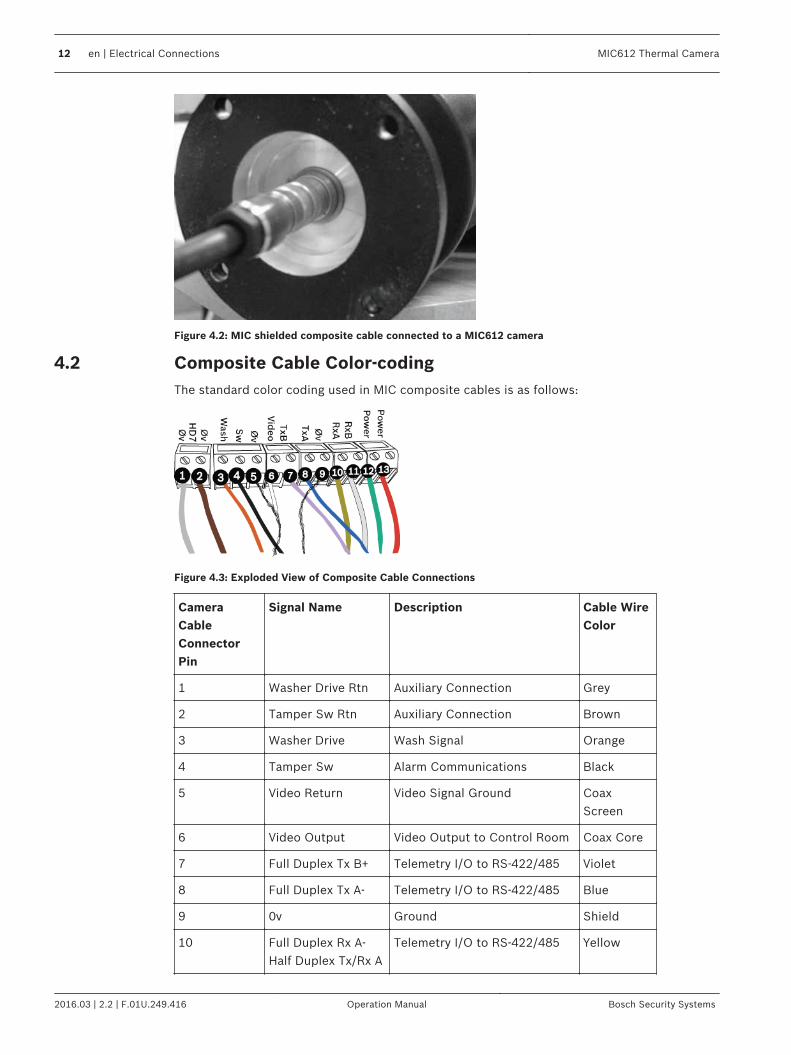
Figure 4.2: MIC shielded composite cable connected to a MIC612 camera
Composite Cable Color-codingThe standard color coding used in MIC composite cables is as follows:
Figure 4.3: Exploded View of Composite Cable Connections
CameraCableConnectorPin
Signal Name Description Cable WireColor
1 Washer Drive Rtn Auxiliary Connection Grey
2 Tamper Sw Rtn Auxiliary Connection Brown
3 Washer Drive Wash Signal Orange
4 Tamper Sw Alarm Communications Black
5 Video Return Video Signal Ground CoaxScreen
6 Video Output Video Output to Control Room Coax Core
7 Full Duplex Tx B+ Telemetry I/O to RS-422/485 Violet
8 Full Duplex Tx A- Telemetry I/O to RS-422/485 Blue
9 0v Ground Shield
10 Full Duplex Rx A-Half Duplex Tx/Rx A
Telemetry I/O to RS-422/485 Yellow
4.2
12 en | Electrical Connections MIC612 Thermal Camera
2016.03 | 2.2 | F.01U.249.416 Operation Manual Bosch Security Systems

CameraCableConnectorPin
Signal Name Description Cable WireColor
11 Full Duplex Rx B+Half Duplex Tx/Rx B
Telemetry I/O to RS-422/485 White
12 Power Input 2 Low Voltage Power Input Green
13 Power Input 1 Low Voltage Power Input Red
MIC612 Thermal Camera Electrical Connections | en 13
Bosch Security Systems Operation Manual 2016.03 | 2.2 | F.01U.249.416

Install the MIC (standard) PSU
MIC PSU Overview
!
Caution!
Use only the power supply specified for your specific model of camera.
Bosch provides a range of power supply units (PSUs) for MIC Series cameras. These unitshave a variety of common voltages and provide all the connections needed for power,telemetry and video.
Model Number Input Voltage Dimensions(H x W x D)
Weight
MIC-24PSU-2 24 VAC 90 x 260 x 160 mm(3.54 x 10.24 x 6.3 in.)
3.2 kg (7.1 lb)
MIC-115PSU-2 115 VAC 90 x 260 x 160 mm(3.54 x 10.24 x 6.3 in.)
3.2 kg (7.1 lb)
MIC-240PSU-2 230 VAC 90 x 260 x 160 mm(3.54 x 10.24 x 6.3 in.)
3.2 kg (7.1 lb)
Table 5.1: PSUs for MIC612
Each MIC PSU provides all of the connections needed for power, video, and telemetry for asingle MIC camera. Each MIC PSU has CE and FCC approval and has a cast-aluminumenclosure that is weather-resistant (rated IP65). Features include:– A provision for driving various optional interface cards mounted internally to the MIC
power supply enclosure (for example, an 8-input alarm card (MIC-ALM))– A provision for a signal interface card (MIC-BP4) to connect telemetry to Bosch Biphase
equipment– Screw termination of all cables (composite, telemetry, and ancillary) into and out of the
enclosure– Earth isolation and termination within the unit to control video earthing correctly and
thus prevent earth loopsEach MIC PSU ships with the following parts:– Three (3) M12 cable glands for telemetry, video and ancillary equipment– One (1) M16 gland for connection of the shielded composite cable to the MIC camera– One (1) 1/2 in. NPT cable gland for the power cable connection– One (1) 1/2 in. NPT and one (1) M12 blanking plug
About the MIC Shielded Composite CableAll connections (power, telemetry, video) to the MIC camera are provided through the screwterminal connections in the MIC power supply. MIC shielded composite cables are multi-conductor cables of various lengths (and gauges ranging from 14 - 18) that provide all power,video, and telemetry connections between the MIC PSU and the MIC camera. The cables arepre-made with a female terminated connector (14-pin) at one end for attachment to the maleconnector installed into the base of the camera. The other end of the cables has free (non-
5
5.1
5.2
14 en | Install the MIC (standard) PSU MIC612 Thermal Camera
2016.03 | 2.2 | F.01U.249.416 Operation Manual Bosch Security Systems

terminated) wires for wiring into terminals in the MIC PSU. The composite cable consists oftwo pairs (24AWG) plus 4 cores of (22 AWG), 2 cores of (24 AWG), and one coax core for thevideo signal to a maximum distance of 25 m.
Notice!
Bosch Security Systems does not recommend using the shielded composite cable for
distances greater than 25 m between the MIC camera and the MIC power supply.
For installations that require the camera to be more than 25 m from the power supply, Boschrecommends that a 2 m cable be connected to a junction box (Exd rated for MIC440) fromwhich telemetry, video, and power can be broken out into separate cables and appropriatewiring used to extend the distance to suit.
!Warning!
Bosch recommends connecting the cable to the unit before taking the unit for mounting on-
site.
Figure 5.1: MIC shielded composite cable connection before cable is connected to a MIC612 camera
Figure 5.2: MIC shielded composite cable connected to a MIC612 camera
Composite Cable Color-codingThe standard color coding used in MIC composite cables is as follows:
5.3
MIC612 Thermal Camera Install the MIC (standard) PSU | en 15
Bosch Security Systems Operation Manual 2016.03 | 2.2 | F.01U.249.416

Figure 5.3: Exploded View of Composite Cable Connections
CameraCableConnectorPin
Signal Name Description Cable WireColor
1 Washer Drive Rtn Auxiliary Connection Grey
2 Tamper Sw Rtn Auxiliary Connection Brown
3 Washer Drive Wash Signal Orange
4 Tamper Sw Alarm Communications Black
5 Video Return Video Signal Ground CoaxScreen
6 Video Output Video Output to Control Room Coax Core
7 Full Duplex Tx B+ Telemetry I/O to RS-422/485 Violet
8 Full Duplex Tx A- Telemetry I/O to RS-422/485 Blue
9 0v Ground Shield
10 Full Duplex Rx A-Half Duplex Tx/Rx A
Telemetry I/O to RS-422/485 Yellow
11 Full Duplex Rx B+Half Duplex Tx/Rx B
Telemetry I/O to RS-422/485 White
12 Power Input 2 Low Voltage Power Input Green
13 Power Input 1 Low Voltage Power Input Red
Earth Link on PCBThe printed circuit board (PCB) of each MIC PSU (IR and non-IR) has one Earth Link option,near terminal block HD1, to allow the PSU to be set up for different earthing schemes:– If there is a separate connection between video screen and earth, the Earth Link should
be broken. This usually occurs on copper-connected systems where all of the coppervideo coaxes are taken back to the control room to be connected to a central earth point.
– If fiber optics or other indirect connections are used to get data and video to and fromthe control room, then the Earth Link should be left intact, as long as it is the onlycamera-end earth reference point.
5.4
16 en | Install the MIC (standard) PSU MIC612 Thermal Camera
2016.03 | 2.2 | F.01U.249.416 Operation Manual Bosch Security Systems

Fuse RatingsThe MIC PSUs for MIC612 cameras have four (4) off 20 mm fuses (numbers 13 - 16 in thefigure “Layout of MIC-240PSU-2 and MIC-115PSU-2”) in fuse holders. The ratings for thesefuses are fixed on the low voltage secondary side but change with input voltage on the highvoltage primary side. The following table shows the fuse values that should be fitted toprovide proper protection for the MIC-240PSU-2 and MIC-115PSU-2 power supplies. Note: FS4 does not exist.
Fuse ID Fuse Function Type Rating for 240 VPrimary
Rating for 115 VPrimary
Rating for 24 VPrimary
FS 1 MIC cameraprotection
Glass 1.6 A anti-surge (T) 1.6 A anti-surge (T) 1.6 A anti-surge (T)
FS 2 Primary protection Glass 200 mA quick blow 500 mA quick blow 2.5 A quick blow
FS 3 Heater protection1
Glass 1.6 A anti-surge (T) 1.6 A anti-surge (T) 1.6 A anti-surge (T)
FS 5 Heater protection2
Glass 1.6 A anti-surge (T) 1.6 A anti-surge (T) 1.6 A anti-surge (T)
Alarm InputsThe table below identifies the number of alarm inputs and outputs available in MIC powersupply units, depending on whether or not an 8-input alarm card is installed.
MIC PSU 8-input Alarm Card(MIC-ALM)?
Number of Alarm Inputs
Number of Alarm Outputs
MIC-24PSU-2,MIC-115PSU-2,MIC-240PSU-2
No 1 0
Yes 8 2
Table 5.2: Number of alarm inputs and outputs in MIC PSUs
Layout of MIC Power Supply Units (PSUs)Layout of MIC-240PSU-2 and MIC-115PSU-2The figure below displays the layout of the PCB in the MIC PSUs for non-IR cameras, with call-out numbers to the side of or below the connection/terminal ID or the terminal, and ’on’ thefuses. The table below the figure identifies the connections.
5.5
5.6
5.7
MIC612 Thermal Camera Install the MIC (standard) PSU | en 17
Bosch Security Systems Operation Manual 2016.03 | 2.2 | F.01U.249.416

Figure 5.4: Layout of MIC-240PSU-2 and MIC-115PSU-2
No. PCBMarking
Description/Function ofConnection / Terminal
Type of Connection/Terminal
1 HD1 AC Power input connectorLive (HD1-1); Neutral (HD1-2)[Ground wire connects to earth termination post
Screw terminal
2 HD3 Shielded composite cable header (connections to camera) Screw terminal
3 HD5 RS-485 control header Screw terminal
4 HD4 Telemetry header Molex connector
5 HD8 USB to RS-485 converter[Not used for MIC440.]
Molex connector
6 HD6 [Optional] Auxiliary, heater[Not used for MIC440.]
Screw terminal
7 HD7 Video (composite cable) Screw terminal
8 HD2 Tamper switch header Screw terminal
9 CN3Video Switched
Coax connection (Switched visible/thermal video out)[Not used for MIC440.]
BNC socket
10 CN1Video Out
Coax connection header(Visible video out)
BNC socket
11 CN2 Auxiliary / add-on card terminal Plug in
12 Earth Link Earth Link
18 en | Install the MIC (standard) PSU MIC612 Thermal Camera
2016.03 | 2.2 | F.01U.249.416 Operation Manual Bosch Security Systems

No. PCBMarking
Description/Function ofConnection / Terminal
Type of Connection/Terminal
13 FS2 Fuse 2 - Primary protection --
14 FS1 Fuse 1 - MIC camera protection --
15 FS3 Fuse 3 - Heater protection 1 --
16 FS5 Fuse 5 - Heater protection 2 --
17 -- Earth termination post Ring terminal
Installation Warnings and Prerequisites
Danger!
ELECTRICAL SHOCK HAZARD
To reduce the risk of electrical shock, disconnect power before opening or working on any
power supply unit. Power must be disconnected before replacing any fuse in the MIC PSU.
Power supply units have power supplied whenever the power cord is inserted into the power
source.
MIC PSUs have a separate internal shield covering the power cable input terminal block
(HD1). Only suitably qualified persons should remove this shield and connect the mains power
cable. The shield MUST be re-installed and fully secured before connecting the power.
The power supply cable shall have conductors of a maximum size of 12 AWG.
Branch circuit protection incorporating a 15 A, 2-pole, listed circuit breaker or branch rated
fuses are required. A readily accessible 2-pole disconnect device with a contact separation of
at least 3mm must be incorporated externally to the equipment.
!
Warning!
To meet UL standards and ratings, all external wires (power and I/O cabling) for installation
applications to the device must be routed separately through different permanently earthed
metal conduits (not supplied).
Notice!
Use only UL-listed liquid tight strain reliefs for conduits to the power supply box to ensure
that water cannot enter the box. You must use watertight conduits and fittings to meet NEMA
6P or to maintain IP68 standards.
Notice!
MIC PSU enclosures are not EXD rated and must be replaced with a certified enclosure if
installed within a hazardous area.
!
Caution!
Except for the Earth Link, heater links, and applicable fuses, the MIC PSUs have no user-
adjustable parts. MIC cameras have no user-serviceable parts.
5.8
MIC612 Thermal Camera Install the MIC (standard) PSU | en 19
Bosch Security Systems Operation Manual 2016.03 | 2.2 | F.01U.249.416
Notice!
Do not connect MIC IR units to a MIC PSU with the heater option enabled as this can damage
the cameras. Ensure that an IR power supply is used with a MIC IR camera unit. Heaters are
available for MIC612 cameras only.
!
Caution!
Bosch recommends using an uninterruptible power supply (UPS) in connection with a MIC
camera/PSU installation.
Notice!
To maintain the IP rating of the power supply enclosure, install only listed or recognized
conduit hubs or fittings with the same environmental rating as the enclosure in compliance
with the installation instruction of the hub or fitting.
Notice!
Refer to the MIC Series Power Supply Installation Manual included with the PSU for full details
on installing a MIC Series PSU and connecting to a MIC Camera.
Installation Instructions (Power Supply)To install the power supply unit (PSU), follow these steps:1. Select a secure installation location for the PSU. Ideally, this is a location where the devicecannot be interfered with either intentionally or accidentally.Bosch recommends using an environmentally suitable, lockable equipment cabinet.2. Loosen the four (4) captive Phillips head screws on the top of the lid of the power supplyenclosure. Lift the lid and set it upside down next to the enclosure.
Notice!
Do not stretch or cut, or otherwise disturb, the earth core cable (shown in the figure below)
to the inside of the lid and to the earth termination post.
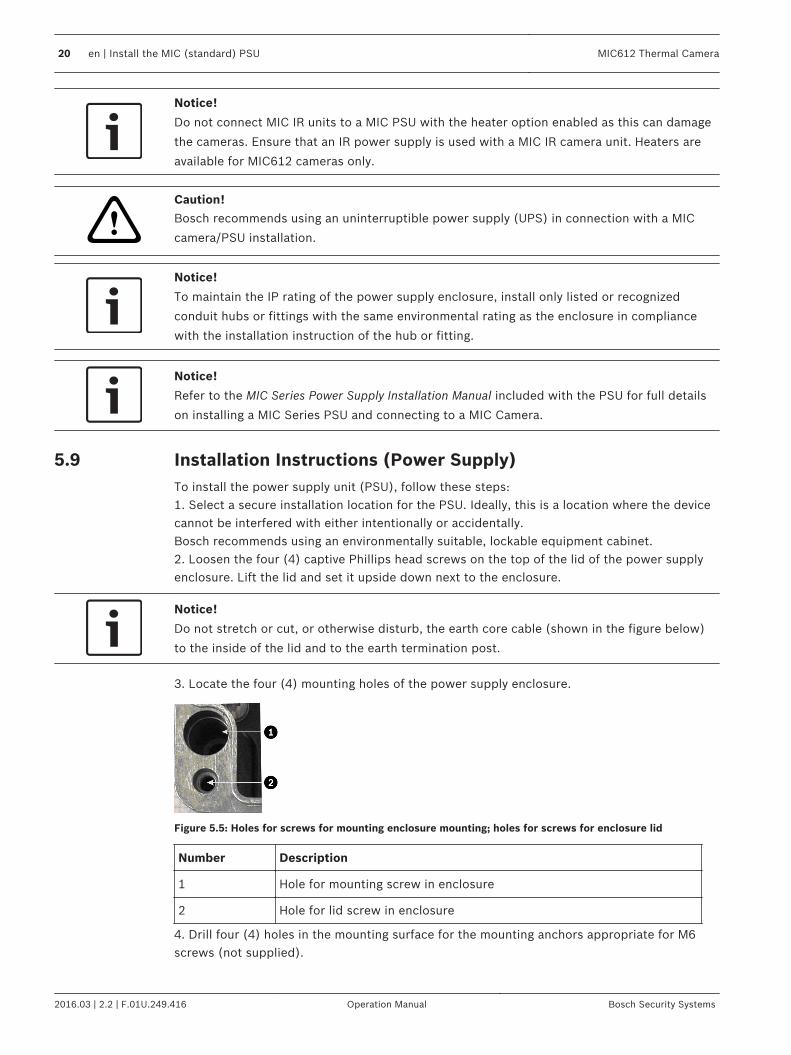
3. Locate the four (4) mounting holes of the power supply enclosure.
Figure 5.5: Holes for screws for mounting enclosure mounting; holes for screws for enclosure lid
Number Description
1 Hole for mounting screw in enclosure
2 Hole for lid screw in enclosure
4. Drill four (4) holes in the mounting surface for the mounting anchors appropriate for M6screws (not supplied).
5.9
20 en | Install the MIC (standard) PSU MIC612 Thermal Camera
2016.03 | 2.2 | F.01U.249.416 Operation Manual Bosch Security Systems

5. Secure the enclosure to the mounting surface using four (4) M6 stainless steel screws andwashers (not supplied), which fit through the large holes in the enclosure.
Notice!
If you are securing the power supply enclosure in a vertical position (for example, on a wall),
one person should hold the enclosure lid while another secures the enclosure body in place,
to avoid damage to any part of the enclosure, and/or injury to the installer(s).
6. Unscrew the two (2) M3 screws on the internal high voltage input head-end shield (markedwith "Danger") covering the mains cable terminal HD1; retain the screws.
Figure 5.6: Enclosure showing shield and earth core cable between earth terminal post and enclosure lid
Number Description
1 Earth core cable to enclosure lid
2 Internal shield
3 Earth termination post
7. Remove the internal shield and set it nearby, outside of the PSU enclosure. You can nowaccess the hole for the power cable and the M20 blanking plug covering the hole.8. Remove the blanking plug covering the hole for the power cable. Install suitable (metal)conduit (not supplied) in the hole. Secure the conduit as recommended by the conduitmanufacturer.
!
Caution!
Only installations with conduit meet UL standards. If you choose to use a power cord without
conduit (not recommended), fit the 1/2 in. NPT cable gland (supplied) in place of the
blanking plug. Note: It is easier to fit the power cord through the cable gland outside of the
enclosure, and then attach the gland to the enclosure. Ensure that the cable glands have
sufficient room to allow for the cables to enter (approximately 60 mm on either side of the
enclosure).
9. Prepare the power cable as needed, and then feed the cable into the enclosure.10. Connect the Live and Neutral cores to the correct screw terminals on terminal block HD1as identified in the table below and printed on the PCB. Observe polarity and voltage.
MIC612 Thermal Camera Install the MIC (standard) PSU | en 21
Bosch Security Systems Operation Manual 2016.03 | 2.2 | F.01U.249.416

PCB Marking Description
L Live
N Neutral
Earth / Ground
11. Remove the brass nut and copper washer from the earth termination post (item 3 in thefigure “Mains input with shield removed…”); set these aside.12. Remove the ring terminal (supplied).13. Insert the earth core from the mains cord (item 2 in the figure “Mains input with shieldremoved…”) into the crimp portion (size M6, UL-certified) of the ring terminal and crimp it inplace.14. Place the ring terminal onto the earth termination post.15. Replace the copper washer. Secure with the brass nut.
Figure 5.7: Mains input with shield removed, showing terminal block HD1 before wiring
Number Description
1 Earth core cable to enclosure lid
2 Earth core cable to power supply PCB
3 Earth termination post
16. Replace the internal shield, taking care to avoid pinching the cables. Tighten the screws.17. Feed the unconnected end of the shielded composite cable through the top-right M16cable gland (item 2 in the figure “MIC PSU Enclosure, with cable glands identified”).
22 en | Install the MIC (standard) PSU MIC612 Thermal Camera
2016.03 | 2.2 | F.01U.249.416 Operation Manual Bosch Security Systems

Figure 5.8: MIC PSU Enclosure, with cable glands identified
Number Description Cable Gland Size
1 Optical Video out M12
2 Composite cable M16
3 Optional switched video output M12
4 Head-end / Telemetry controls M12
18. Connect the shielded composite cable to terminal block HD3 (and, if necessary, HD6 andHD7) following the color coding as shown in the figure below, and printed on the PCB.
No.
ID, Connection/Terminal + Pin
PCB Mark,Signal
Description/Function of Connection PCB Mark, Cable Color
1 HD3-1 Power Low Voltage Power (Input 1) / AC supply Red
2 HD3-2 Power Low Voltage Power (Input 2) / AC supply return Green
3 HD3-3 RxB Telemetry I/O to RS-422/485 [Rx +]Full Duplex RxB/Half Duplex Tx/RxB
White
4 HD3-4 RxA Telemetry I/O to RS-422/485 [Rx -] Full DuplexRxA/Half Duplex Tx/RxA
Yellow
5 HD3-5 0v Ground [Drain Wire / Shield] Screen (Black)
6 HD3-6 TxA Telemetry I/O to RS-422/485 [Tx -] Full DuplexTxA
Blue
7 HD3-7 TxB Telemetry I/O to RS-422/485 [Tx +] Full DuplexTxB
Violet
8 HD3-8 Video Video output of optical camera to Control Room(Coax - BNC CN1)
Core
9 HD3-9 Video 0V Video signal return (optical camera) (ground toControl Room) (Coax - BNC CN1)
Screen
10 HD3-10 Tamp Sw [Optional] Tamper Switch Black
11 HD3-11 Wash [Optional] Washer Drive Signal Orange
MIC612 Thermal Camera Install the MIC (standard) PSU | en 23
Bosch Security Systems Operation Manual 2016.03 | 2.2 | F.01U.249.416

No.
ID, Connection/Terminal + Pin
PCB Mark,Signal
Description/Function of Connection PCB Mark, Cable Color
12 HD6-1 AUX1 [Optional] Auxiliary Connection (heater) Brown
13 HD6-2 AUX2 [Optional] Auxiliary Connection (heater) Grey
14 HD7-1 -- Video Switched Output to Control Room(Switched visible/thermal video out signal)
Core (Black)
15 HD7-2 -- Switched video signal ground Screen (Black)
Note: If connecting a heater, see Commissioning the Camera with Heater Option Fitted, page28.
Notice!
MIC440 cameras do not have an internal heater.
Notice!
You must connect the overall shield drain wire of the composite cable to the power supply
chassis in order to ground the chassis. Crimp the drain wire to the ring terminal lug attached
to the mounting screw of the PCB located to the right of BNC socket CN3 (Video Switched).
Refer to Layout of MIC-240PSU-2 and MIC-115PSU-2, page 17 for the location of the screw.
19. Slide back the cable so that the shield is in the middle of the gland.20. Tighten the cable gland so that it grips firmly the shielded composite cable. It is importantthat the braided cable screen engages with the internal clamps of the cable gland to ensurecorrect EMC protection.21. If necessary, connect a tamper switch to terminal block HD2.22. Make the necessary video connections. Feed the coaxial cable of your choice--see the tablebelow to identify the recommended cable types, maximum distance, and other specificationsfor the coax video connection between the MIC power supply and the head-end controlsystem--through the top-left M12 cable gland (item 1 in the figure “MIC PSU Enclosure, withcable glands identified”).
Cable Type; MaximumDistance
RG-59/U; 300 m (1000 ft)RG-6/U; 450 m (1500 ft)RG-11/U; 600 m (2000 ft)
Size O.D. between 4.6 mm (0.181 in.) and 7.9 mm(0.312 in.)
Shield Copper braid: 95%
Central Conductor Standard copper center
23. Crimp the end of the cable with a BNC terminal connector.24. Connect the Video Out cable to BNC socket CN1.For dual video output only: If needed, remove the blanking plug that covers the hole for thebottom-left M12 cable gland (item 3 in the figure “MIC PSU Enclosure, with cable glandsidentified”). Feed a second Video Out cable through the cable gland, and then connect the
24 en | Install the MIC (standard) PSU MIC612 Thermal Camera
2016.03 | 2.2 | F.01U.249.416 Operation Manual Bosch Security Systems

switched Video Out cable to BNC socket CN3. This second cable provides control for videofrom both the optical camera and the thermal camera; users can switch between the twocameras.25. Feed telemetry cable through the bottom-right M12 cable gland (item 4 in the figure “MICPSU Enclosure, with cable glands identified”).26. Connect head-end RS-485 control to terminal block HD5, as indicated in the table below:
PCB Marking(non-IR PCBs)
Telemetry Signal Name Connection Description / Function Pin Number
RxB Rx + RS485+ to camera 1
RxA Rx - RS485- to camera 2
0V Ground 0V from control room 3
TxA Tx - RS485- to control room 4
TxB Tx + RS485+ to control room 5
Note: The terminal block is positioned with the screw terminals on the left, next to the fuses.Pins are numbered from top to bottom in that orientation. Non-IR PSU PCBs are marked.27. If connecting to additional add-on cards (for example, a card for 8-input alarms (MIC-ALM), and/or a Biphase card (MIC-BP4)), remove the second blanking plug that covers one ofthe holes for an M12 cable gland (item 3 in the figure “MIC PSU Enclosure, with cable glandsidentified”). Attach the supplied M12 gland. Make the appropriate connections to plug-interminal CN2.
Notice!
For installation of the MIC 8-input Alarm Card (MIC-ALM) or Biphase converters (MIC-BP3 or
MIC-BP4), please refer to their respective manuals.
4 For physical alarm connections on MIC IR power supplies, connect alarm input cables toterminal block HD2, as indicated in the table below:
Signal PinNumber
Alarm 1 1
0 V 2
Alarm 2 3
0 V 4
Alarm 3 5
0 V 6
Alarm 4 7
0 V 8
4 On MIC IR power supplies, a washer drive is standard. A 24 VAC rated relay is fitted via theonboard fuse FS4 (rated at 2.5 Amps). Make the following washer pump connections toterminal block HD7 (marked Washer Drive on the PCB):
MIC612 Thermal Camera Install the MIC (standard) PSU | en 25
Bosch Security Systems Operation Manual 2016.03 | 2.2 | F.01U.249.416

Signal PinNumber
WasherPump
1
WasherPump
2
!Warning!
The washer pump terminal is rated only to 24 VAC or VDC maximum voltage and is not
suitable for Mains-operated pumps.
4 Test the washer by pressing the red button marked SW1 PUMP ON on the PCB. LED 3 illuminates in response to telemetry commands from the control room to turn onthe washer. Note that the software in the camera prevents the washer from running morethan 10 seconds continuously to prevent emptying the washer bottle.
28. After wiring is complete, connect the power supply to the power source.29. Verify that the following LEDs are lit:
LED Description
LED 2 18 VAC power on to camera
LED 4 Power on for optional heater
LED 3 18 VAC power on camera
LED 5 Power on for optional heater
26 en | Install the MIC (standard) PSU MIC612 Thermal Camera
2016.03 | 2.2 | F.01U.249.416 Operation Manual Bosch Security Systems

Figure 5.9: Position of LEDs - MIC Series power supply PCB
MIC612 Thermal Camera Install the MIC (standard) PSU | en 27
Bosch Security Systems Operation Manual 2016.03 | 2.2 | F.01U.249.416

Figure 5.10: Position of LEDs - MIC Series IR power supply PCB
Number LED Description
1 LED 1LED 2
Indicates that 18 VAC is available from the power supply and that thesupply fuses are intact.
2 LED 3 Illuminates when the washer drive is on.
3 LED 4 Monitors the internally generate +5 V.
4 LED 5 Illuminates when the IR lamp supply is turned on by the cameratelemetry.
5 LED 6 Status LED. Pulses On/Off when Multi Alarm is selected.
6 LED 7-10 Illuminate when the associated alarm is active.
30. Re-attach the enclosure lid and tighten the four (4) captive screws on the cover to ensurethat the enclosure is watertight.
Commissioning the Camera with Heater Option FittedTo enable the heaters, you must change two links on the printed circuit board (PCB) of thepower supply. Follow these steps:1. Disconnect the power supply from the power source.2. Locate Link 1 and Link 2 on the PCB, next to terminal block HD6. The default setting is
0V.
5.10
28 en | Install the MIC (standard) PSU MIC612 Thermal Camera
2016.03 | 2.2 | F.01U.249.416 Operation Manual Bosch Security Systems

Figure 5.11: PCB links set to 0V
3. Break the two solder links and remove any excess solder.4. Solder the links, using TCW link wire, from the left hand pads to the middle pads. The
power supply will now deliver 18 VAC to terminal block HD6.
Figure 5.12: PCB links set to 18V
MIC612 Thermal Camera Install the MIC (standard) PSU | en 29
Bosch Security Systems Operation Manual 2016.03 | 2.2 | F.01U.249.416

5. Locate the Brown and Grey wires from the composite cable.6. Connect the heater wires Brown and Grey to terminal block HD6 as labelled on the PCB.
The heaters are thermostatically controlled and will automatically turn on at +5 °C (+41°F) and turn off at +15 °C (+59 °F).
7. Check all connections.8. Close the PSU enclosure.9. Reconnect the power supply to the power source.
Simultaneous IP and Analog Video/Control ("Hybrid"Operation)The figure below illustrates how to configure your system to achieve simultaneous video andcontrol over both IP and analog connections.
Figure 5.13: System configuration for simultaneous video/control
Number Description
1 Connection between MIC camera and BNC T-connector in BNC socket on PCB inMIC IP PSU
2 Connection between BNC T-connector and encoder in MIC IP PSU
3 Connection between BNC T-connector and Bilinx-based control (head-end) system
4 Connection between Bilinx-based control (head-end) system and Local AreaNetwork (LAN) (or the "cloud")
5 Connection between the Local Area Network (LAN) and PC connected to videomonitor
5.11
30 en | Install the MIC (standard) PSU MIC612 Thermal Camera
2016.03 | 2.2 | F.01U.249.416 Operation Manual Bosch Security Systems

Fit the Sunshield (MIC612)The MIC612 Sunshield is designed to provide additional protection against direct solarradiation. It is a two-part molding and comes supplied with eight (8) stainless steel stand-offsand eight (8) stainless steel M3 washers and retaining screws.The MIC612 stand-offs are slightly shorter than those for the MIC412 and have gnarledthreads at one end. The MIC412 stand-offs are slightly longer and are smooth at one end.
Stand-off for MIC612 Stand-off for MIC412
The MIC612 Sunshield is designed to provide additional protection against direct solarradiation. It is a two-part molding and comes supplied with eight (8) stainless steel stand-offsand eight (8) stainless steel M3 washers and retaining screws.
!
Caution!
DO NOT REMOVE the lid from the camera, and do not back drive the pan or tilt axis manually.
Doing so will void the warranty. Back driving may also strip teeth off the internal gears.
Figure 6.1: Graphical depiction of sunshield assembly
1 Stand-off, stainless steel
2 Sunshield
3 M3 x 10 mm screw, stainless steel, Pozidriv with pan head
4 M3 washer, stainless steel
6
MIC612 Thermal Camera Fit the Sunshield (MIC612) | en 31
Bosch Security Systems Operation Manual 2016.03 | 2.2 | F.01U.249.416
To fit the sunshield, follow these steps:1. Turn on the power to the camera so that you can rotate the camera head up to fit the
bottom half of the sunshield (see step 8).2. Rotate the camera under power—do not rotate by hand—until the bottom of the camera
head is facing up.3. Remove the four (4) retaining bolts from the lid of the camera.4. Place a stand-off into each screw hole and tighten using a flat head screwdriver.5. When all four (4) stand-offs have been fitted, align the holes in the sunshield with the
corresponding stand-offs. Push the sunshield until it fits snugly onto the camera head.6. Fix the sunshield to the stand-offs using the M3 washers and screws.7. Rotate the camera under power—do not rotate by hand—until the top of the camera head
is facing up.8. Repeat steps two through six on the top lid of the camera. When fitted properly, both
halves of the sunshield should align and meet at the back of the camera head.
32 en | Fit the Sunshield (MIC612) MIC612 Thermal Camera
2016.03 | 2.2 | F.01U.249.416 Operation Manual Bosch Security Systems

Getting StartedInstall and wire the camera according to the instructions in this manual and in the manualsthat accompany the power supply and mounting devices. A typical system includes akeyboard, matrix switcher, monitor, and appropriate wiring connections. Refer to theindividual product manuals for complete installation and setup instructions for each of thesystem components.
Establishing Control of the CameraThe MIC Series 612 supports two communication protocols (Biphase and RS-485), and bothBosch and Pelco D and P (keyboard) controller protocols that allow you to send commands tothe camera and to receive information from the camera.
Establishing Control of the Camera via Biphase Protocol
Notice!
Biphase protocol works only with Bosch controller protocol. It does not work with Pelco
controller protocol.
Biphase is the standard Bosch protocol used to send Pan/Tilt/Zoom control data. Biphaseconnections require a MIC-BP3 or a MIC-BP4 Biphase converter (sold separately).
Cable Type Shielded Twisted Pair (STP)
System Half-duplex, multidrop
Maximum Distance 1524 m (5000 ft) [Belden 8760recommended]
Transmission Rate 31.25 KHz
Gauge 1.02 mm (18 AWG)
TerminationResistance
100 Ω
Terminal Connector Screw terminals
Voltage 4 Vp-p
!
Caution!
The Biphase shield must be connected to the head end only.
Establishing Control of the Camera via RS-485 ProtocolUsers can connect viaa) A computer -> RS-232 -> RS-232 to RS-485 converter -> MIC612orb) A computer -> USB to RS-485 -> MIC612.RS-485 is capable of controlling a true multidrop network and is specified for up to 32 driversand 32 receivers on a single 2-wire bus.
7
7.1
7.1.1
7.1.2
MIC612 Thermal Camera Getting Started | en 33
Bosch Security Systems Operation Manual 2016.03 | 2.2 | F.01U.249.416

The MIC612 camera can be connected in a 2- or 4-wire mode. Available connection protocolsare: Pelco, Bosch OSRD (via a keyboard with RS-485 output), Bicom over serial (via CTFIDsoftware; see the CTFID User Manual for installation details), and Forward Vision protocols.
Cable / Wire Type Shielded Twisted Pair (STP)
System Half-duplex, differential, multidrop
Maximum Distance 1219 m (4000 ft)
Maximum Baud Rate 57.6 kb
Gauge 0.511 mm (24 AWG)
Wire Impedance 120 Ω
!
Caution!
Bosch recommends that multiple RS-485 connections be arranged as a connected series of
point-to-point (multidropped) nodes, as a line or as a bus. It is not recommended to arrange
RS-485 connections as a star, ring, or as a multiple-connected network. Star and ring
topologies may cause signal reflections or excessively low or high termination impedance.
In Pelco Protocol Mode, the camera is configured from the factory for RS-485 operation.1. Connect the controller's Tx terminals to the Tx terminals in the power supply box. See the
MIC Series Power Supplies Installation Manual for complete wiring instructions.2. Pan or tilt the keyboard joystick to confirm that control has been established to the
camera (approximately five (5) seconds).
Powering OnWhen you turn on power to the camera, a splash screen or text displays the type of device(MIC612), the camera model, the video type (PAL or NTSC), the firmware version, and (ifapplicable) the MAC address.
About Setting the Camera Address via FastAddressThe camera offers remote addressing via the feature "FastAddress," which allows you to set orto change a camera address using the keyboard and on-screen menus. The FastAddressfeature allows you to install all cameras first, then to set the addresses via the control system.This feature makes it easier to re-address cameras at a later time because you do not need togo to the physical location of the camera to change the camera’s address.
Notice!
FastAddress applies to the optical camera only; it does not apply to the thermal camera.
Notice!
You do not need to set a camera address if using Bilinx communication.
FastAddress is stored in nonvolatile memory and does not change if the power is turned off
or if the default settings are restored.
7.2
7.3
34 en | Getting Started MIC612 Thermal Camera
2016.03 | 2.2 | F.01U.249.416 Operation Manual Bosch Security Systems
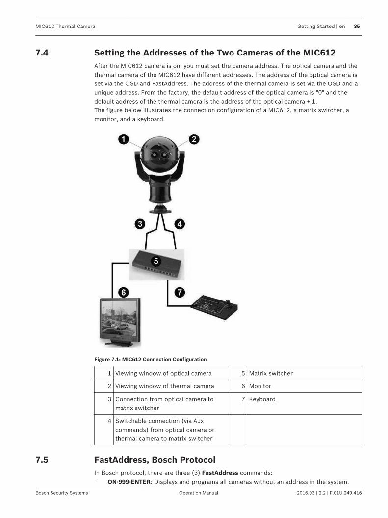
Setting the Addresses of the Two Cameras of the MIC612After the MIC612 camera is on, you must set the camera address. The optical camera and thethermal camera of the MIC612 have different addresses. The address of the optical camera isset via the OSD and FastAddress. The address of the thermal camera is set via the OSD and aunique address. From the factory, the default address of the optical camera is "0" and thedefault address of the thermal camera is the address of the optical camera + 1.The figure below illustrates the connection configuration of a MIC612, a matrix switcher, amonitor, and a keyboard.
Figure 7.1: MIC612 Connection Configuration
1 Viewing window of optical camera 5 Matrix switcher
2 Viewing window of thermal camera 6 Monitor
3 Connection from optical camera tomatrix switcher
7 Keyboard
4 Switchable connection (via Auxcommands) from optical camera orthermal camera to matrix switcher
FastAddress, Bosch ProtocolIn Bosch protocol, there are three (3) FastAddress commands:– ON-999-ENTER: Displays and programs all cameras without an address in the system.
7.4
7.5
MIC612 Thermal Camera Getting Started | en 35
Bosch Security Systems Operation Manual 2016.03 | 2.2 | F.01U.249.416

Notice!
If a keyboard is set to a camera number that already has an address, that camera also
responds to this command.
– ON-998-ENTER: Displays and programs all cameras with or without an address in thesystem.
– ON-997-ENTER: Displays the current address status of all cameras in the systemsimultaneously.
To set an address for a camera without an address:1. Select the camera number that you want to FastAddress. The system displays the camera
number on the keyboard and the image on the corresponding monitor.2. Press #-ENTER (where # is the camera number without an address).3. Press ON-999-ENTER to invoke an on-screen display of cameras on the system without an
address.4. Follow the on-screen instructions. You receive an on-screen confirmation when the
FastAddress is complete.To change or clear an address for a camera with an address:1. Select the camera number that you want to FastAddress. The system displays the camera
number on the keyboard and the image on the corresponding monitor.2. Press #-ENTER (where # is the camera number with an address).3. Press ON-998-ENTER to invoke an on-screen display of all cameras on the system, with or
without an address.4. Follow the on screen instructions. You receive an on-screen confirmation when the
FastAddress is complete.The table below identifies the setting of the thermal camera when you change the address ofthe optical camera of the MIC612.
Default Address,Optical
New Address, OpticalCamera
Address, ThermalCamera
0 A number other than 0 The number of theoptical camera + 1
A number other than 0 0 or another number -No change of address.-
You can change the address of the thermal camera via CTFID; there is no Aux code for this.
FastAddress, Pelco ProtocolsThis section provides instructions to set a FastAddress with a Pelco keyboard or controller.– The optical camera of the MIC612 with an address set to 0 responds to commands set to
any address.– Pelco-P protocol must use addresses 1 to 32.– Pelco-D protocol must use addresses 1 to 254.
Notice!
A previously-configured MIC with an address above 32 (Pelco-P upper limit) or 254 (Pelco-D
upper limit) can be used without readdressing the unit. However, no two (2) addresses can
be the same. For example:
Pelco-P addresses above 32 are repeated in multiples of 32 (1, 33, 65, 97 are the same).
Pelco-D addresses above 254 are repeated in multiples of 254 (1, 255, 509, 763 are the
same).
7.6
36 en | Getting Started MIC612 Thermal Camera
2016.03 | 2.2 | F.01U.249.416 Operation Manual Bosch Security Systems

To set FastAddress with a Pelco Keyboard:1. Press and hold 95-PRESET for two seconds to open the Pelco Setup menu.2. Move the joystick to select the Command Lock menu.3. Press the FOCUS or the IRIS button to turn Command Lock to OFF.4. Move to the FastAddress menu and press the FOCUS button or the IRIS button to open
the menu.5. Use the joystick to enter the unique identifier for the camera.
Move the joystick up or down to select the number.Move the joystick right to move to the next number position.
6. Move the joystick right to select Continue. Then, press the FOCUS or the IRIS button.7. Use the keyboard to enter the FastAddress number. Then, press the Camera button.
Note: To use a FastAddress number that is already assigned to a different camera, youmust clear the number first.
8. Move the joystick down then up again to set the FastAddress number.9. Press the FOCUS or the IRIS button to store the FastAddress number. The on-screen
display menu confirms that the camera stored the FastAddress number.
Active Commands in FastAddressThe table below identifies the commands that will work and those that will not when userssend commands via the FastAddress of the thermal camera:
Commands that will work Commands that will not work
Pan, tilt Menu commands
Thermal camera commands Visible camera commands
Certain Aux commands (list tobe populated)
Certain Aux commands
Setting PasswordsPasswords are used to control access to locked command menus. Unlocked commands areavailable to all users. Passwords are four (4) digits in length.
Special PasswordsThe table below identifies special passwords and their function and security level.
Password Function / Security Level
0000 (default) Enables security and requires a user to enter the unlock command OFF-90-ENTER before invoking a locked command.
9999 Disables all security and allows all users to access lockedcommands.
Setting Passwords, Bosch ProtocolTo set or change a password (locked command):1. Press OFF-90-ENTER to turn off the command lock.2. Press SET-802-ENTER to access the password menu.3. Tilt the joystick up or down to choose a number. Tilt the joystick right to move to the next
number position.4. Follow the on-screen instructions and save the password. You receive an on-screen
confirmation.
7.7
7.8
7.8.1
7.8.2
MIC612 Thermal Camera Getting Started | en 37
Bosch Security Systems Operation Manual 2016.03 | 2.2 | F.01U.249.416

Controlling the CameraThe most common ways to control the MIC are:– Using a keyboard and on-screen display (OSD) menus. This method is the most common.
See Basic Keyboard Operation, page 38.– Using the Configuration Tool for Imaging Devices (CTFID) software running on a PC with
Bilinx or the RS-232/RS-485 communication protocol. Go to www.boschsecurity.com todownload the latest version of the software and the CTFID User Manual.
– Using a PC-based graphical user interface (GUI).
Basic Keyboard OperationThe following tables summarize the basic operations for a standard keyboard and thefunctions available to control a MIC camera.
TypicalKeyboardFeatures
Usage
Function Keys Selects a specific control setting.
Number Keys Inputs a number from 0 to 9.
Camera Key Selects a camera number.
Enter Key Inputs a selection.
Focus Key Sets the lens focus or makes a menu selection in OSD mode.
Iris Key Sets the lens iris setting or makes a menu selection in OSD mode.
Key LEDs Indicates an active key.
LCD Displays the current status.
Joystick Controls the pan/tilt/zoom (PTZ) functions of the camera.
Table 8.1: Typical Keyboard Functions
Camera Operation Control Method
To Pan Side to Side Move the joystick left or right.
To Tilt Up and Down Move the joystick forward and back.
To Zoom In Twist the joystick clockwise.
To Zoom Out Twist the joystick counterclockwise.
Table 8.2: Typical Keyboard Controls for a MIC Camera
Navigating the On-Screen Display (OSD) MenusThe OSD menus provide access to the programmable settings of the camera. The OSDdisplays only the submenus that are applicable to a particular MIC configuration. Some menuitems (indicated as (L)) are locked and require a system password to use. Menu items markedwith an asterisk (*) are default factory settings, unless otherwise noted.
8
8.1
8.2
38 en | Controlling the Camera MIC612 Thermal Camera
2016.03 | 2.2 | F.01U.249.416 Operation Manual Bosch Security Systems

Notice!
After 4.5 minutes of inactivity, the OSD menu times out and exits without warning. Some
unsaved settings in the current menu can be lost.
To navigate the OSD menus:1. Use the joystick to highlight a menu item.2. Press either the Focus or the Iris key to open a menu item.3. Follow the on-screen instructions.Note: To select the Exit Menu item from anywhere in the current menu, use the Zoomcommand.
Keyboard Commands, Bosch ProtocolKeyboard control commands are composed of a sequence of three (3) inputs with thefollowing convention: 1) a Function key + 2) a Command number key(s) + 3) the Enter key.– Depending on the type of keyboard, the control function keys are labeled:
ON or AUX ONOFF or AUX OFFSET or SET SHOTSHOT or SHOW SHOT
Notice!
The convention used for control key commands in this manual is ON, OFF, SET, and SHOT.
Refer to your keyboard manual for the key naming conventions.
– Command numbers range from 1 to 999. See Keyboard Commands (Bosch Protocol) ByNumber, page 86 for a complete list of keyboard commands for Bosch protocol.
– The Enter key can also be labeled with the ∞ symbol.For example, the keyboard command to make the camera pan 360º continuously is:ON-1-ENTER (Press the ON key, then press the number 1 key, and then press ENTER.)Refer to Keyboard Commands (Bosch Protocol) By Number for a complete list of commands.
Keyboard Commands, Pelco ProtocolPelco control commands are composed of a sequence of two (2) keyboard inputs with thefollowing convention: 1) a Command Number and 2) a Function key input.The camera uses the PRESET command key to save and recall presets (pre-positions) 1through 99.
Notice!
To save a preset, enter the desired number and hold the PRESET key for approximately two
(2) seconds. To recall a preset, enter the desired preset number (or command) and
momentarily press and release the PRESET key.
8.3
8.4
MIC612 Thermal Camera Controlling the Camera | en 39
Bosch Security Systems Operation Manual 2016.03 | 2.2 | F.01U.249.416

Keyboard Command User Action Description
0-Pattern Press Initiate recording continuous playback based uponcurrent Recording setting (A or B) in the SetupMenu.
Press and hold Initiate recording based upon current Recordingsetting (A or B) in the Setup Menu. Press ACK toend recording.
1-Pattern Press Initiate Recording A continuous playback.
Press and hold Initiate Recording A. Press ACK to end recording.
2-Pattern Press Initiate Recording B continuous playback.
Press and hold Initiate Recording B. Press ACK to end recording.
3-Pattern Press Initiate the standard preset tour (Tour 1).
4-Pattern Press Initiate the custom preset tour (Tour 2).
1 - Aux On / Aux Off Press Activate / deactivate alarm output 1.This command is supported with Non-IR modelsonly if an optional 8-input alarm card is installed inthe PSU powering the camera.
2 - Aux On / Aux Off Press Activate / deactivate alarm output 2.This command is supported with Non-IR modelsonly if an optional 8-input alarm card is installed inthe PSU powering the camera.
5 - Aux On / Aux Off Press Toggle switchable video output of MIC612 camerabetween visible and thermal output.
91 - Aux On Press Activate Zone Scan (display zone titles).
92 - Aux On Press Deactivate Zone Scan (re-move zone titles).
Special Preset Commands, Pelco ProtocolSome Pelco mode preset commands have a special meaning and override the normal Pelcopreset function as follows:
Preset Command Description
33-PRESET Pans the camera 180° (Flip).
34-PRESET Goes to Zero Pan (original home position).
80-PRESET Toggles the Synchronization Mode between Line Lock and Internal(Pelco Frame Scan). This command is available if commands areunlocked using the Main menu.
81-PRESET Initiates Preset Tour 1.
82-PRESET Initiates Preset Tour 2.
92-PRESET Sets the Left pan limit for an AutoScan with Limit Stops enabled.
93-PRESET Sets the Right pan limit for an AutoScan with Limit Stops enabled.
8.5
40 en | Controlling the Camera MIC612 Thermal Camera
2016.03 | 2.2 | F.01U.249.416 Operation Manual Bosch Security Systems

Preset Command Description
94-PRESET Initiates a Preset Tour.
95-PRESET Enables or disables Limit Stops in the Setup Menu for AutoScan.Invokes the Pelco main Setup Menu when pressed for 2 seconds.
96-PRESET Stops a scan.
97-PRESET Initiates FastAddress (Pelco Random Scan).
98-PRESET Toggles the Synch. Mode between Line Lock and Internal (PelcoFrame Scan). This command is available only for two (2) minutes afterthe power is applied and then reverts to normal preset functionality.
99-PRESET Starts an AutoScan.
Notice!
Some Pelco controllers do not support all of the preset command numbers. Refer to the
documentation of the specific Pelco controller for supported preset commands.
MIC612 Thermal Camera Controlling the Camera | en 41
Bosch Security Systems Operation Manual 2016.03 | 2.2 | F.01U.249.416

On-Screen Display (OSD) Menus (Bosch Protocol)This chapter identifies and describes each OSD menu option, as well as the default setting foreach option, for Bosch protocol. For step-by-step instructions, see Common User Commands,page 76 and Advanced Features, page 78. To open the main Setup Menu (locked commands) in Bosch protocol:1. Press OFF-90-ENTER to turn off the command lock.2. Press ON-46-ENTER to access the Setup Menu. The screen Setup Menu appears.
Setup Menu
Exit...
Camera Setup
Thermal Camera Setup
Lens Setup
PTZ Setup
Display Setup
Communication Setup
Alarm Setup
Language
Advanced
Diagnostics
Focus / Iris: Select
9
42 en | On-Screen Display (OSD) Menus (Bosch Protocol) MIC612 Thermal Camera
2016.03 | 2.2 | F.01U.249.416 Operation Manual Bosch Security Systems

Setup Menu Choices:
Menu Description
Exit Exits the menu.
Camera Setup Accesses adjustable camera settings such as: white balance, gain,sharpness, sync, line lock, backlight, shutter, and night mode.
ThermalCamera Setup
Accesses the settings for the thermal camera.
Lens Setup Accesses adjustable lens settings such as: focus, iris, zoom speed, anddigital zoom.
PTZ Setup Accesses adjustable pan/tilt/zoom (PTZ) settings such as: Autopan, tours,PTZ speed, inactivity period, AutoPivot, and tilt limits.
Display Setup Accesses adjustable display settings such as: OSD, sector blanking, andprivacy masking.
CommunicationSetup
Accesses communication settings such as: AutoBaud and Bilinx.
Alarm Setup Accesses the alarm settings such as: inputs, outputs, and rules.
Language Displays the language.
Advanced
Diagnostics Displays the status of diagnostic events.
Notice!
Each Setup menu contains the following options: Exit (to exit the current menu) and Restore
Defaults (to restore the default settings for the current menu only). The rest of this chapter
identifies specifically only those menu options which are unique to a specific setup menu.
MIC612 Thermal Camera On-Screen Display (OSD) Menus (Bosch Protocol) | en 43
Bosch Security Systems Operation Manual 2016.03 | 2.2 | F.01U.249.416

Camera Setup MenuThe Camera Setup Menu contains settings that can be changed/customized for the optical(visible) camera.
Camera Setup
Exit...
* White Bal: EXT ATW
* Gain Control: AUTO
* Max Gain Level: 6 (4**)
* Sharpness: 12
* Backlight Comp: OFF
WDR: OFF
* Shutter Mode: Auto SensUP
* Shutter: 1/60
* Auto SensUP Max: 15x
* Night Mode: AUTO
* Night Mode Color: OFF
* Night Mode Threshold: 55
* Pre-Comp: 1
Stabilization: ON
Restore Defaults...
* = Factory Setting
Focus / Iris: Select
9.1
44 en | On-Screen Display (OSD) Menus (Bosch Protocol) MIC612 Thermal Camera
2016.03 | 2.2 | F.01U.249.416 Operation Manual Bosch Security Systems

White BalMaintains proper color reproduction (white balance) as the color temperature of a scenechanges (for example, from daylight to fluorescent lighting).
Option Description
Extended ATW (Default setting) Adjusts camera color using extended range.
ATW Adjusts camera color constantly.
Indoor W.B. Optimizes camera color for typical indoor conditions.
Outdoor W.B. Optimizes camera color for typical outdoor conditions.
AWB Hold Sets the camera's color settings for the current scene.
Manual Allows users to adjust the Red and Blue gain. Sliding scale: –(1 to100)+
Outdoor Auto Automatically adjusts camera color in outdoor scenes.
Sodium LampAuto
Automatically adjusts camera color in scenes with sodium vaporlighting.
Sodium Lamp Allows users to adjust color in scenes with sodium vapor lighting.
Gain ControlElectronically brightens darker scenes which may cause graininess in low light scenes.Options: Auto (default setting), OFF. Max Gain LevelAdjusts the maximum gain level to which the gain control adjusts when set to AUTO.Sliding scale: –(1 to 6)+ (1=8db, 2=12db, 3=16db, 4=20db, 5=24db, 6=28db)Default setting: 6 (for 28x camera); 4 (for 36X camera). SharpnessAdjusts the sharpness level of the picture.Sliding scale: –(1 to 16)+. Default setting: 8Backlight CompImproves image quality when the background illumination level is high. Options: ON, OFF(default setting). WDRWide Dynamic Range. Options: ON, OFF (default setting), AUTO. Shutter ModeTurns Auto SensUP on or off. Options: Auto SensUP (default setting), OFF. ShutterAdjusts the electronic shutter speed (AES). Sliding scale: –(60 to 1/10000) +.1/60 sec. (NTSC) or 1/50 sec. (PAL) Auto SensUP Max.
MIC612 Thermal Camera On-Screen Display (OSD) Menus (Bosch Protocol) | en 45
Bosch Security Systems Operation Manual 2016.03 | 2.2 | F.01U.249.416

Sets the limit for sensitivity when the shutter speed is set to Auto SensUP. Options: 2x, 4x,7.5x, 15x (default setting). Night ModeSelects night mode (B/W) to enhance lighting in low light scenes. Options: ON, OFF, AUTO(default setting). Night Mode ColorDetermines if color processing remains in effect while in night mode. Options: ON, OFF(default setting). Night Mode ThresholdAdjusts the level of light at which the camera automatically switches out of night mode (B/W)operation. Sliding scale: –(10 to 55)+, (in increments of 5) 10 is earlier, 55 is later. Defaultsetting: 55 Pre-CompAmplifies the video gain to compensate for long distance cable runs.Sliding scale: –(1 to 10)+. Default setting: 1 StabilizationEliminates shaking of the camera in both the vertical and horizontal axes, resulting inexceptional image clarity without reducing camera sensitivity or picture quality. Options: ON,OFF (default setting).
Thermal Camera Setup MenuThe Thermal Camera Setup Menu contains settings that can be changed for the thermalcamera.
Thermal Camera Setup
Exit...
* Thermal Mode White Hot
* SPOT meter display OFF
* AGC Mode OUTDOOR
* Second Channel Video
Restore Defaults...
* = Factory Setting
Focus/Iris: Select
Thermal Mode
9.2
46 en | On-Screen Display (OSD) Menus (Bosch Protocol) MIC612 Thermal Camera
2016.03 | 2.2 | F.01U.249.416 Operation Manual Bosch Security Systems

Adjusts the display mode for the thermal camera. Options:
Option Description
WhiteHot
(Default setting) Hot objects appear brighter than cold objects.
Black Hot Hot objects appear darker than cold objects.
Fusion Cold objects appear deep blue or purple or black; hot objects appear yellow.
Rainbow Cold objects appear black; hot objects appear red or yellow.
Globow Similar to Fusion, without blue or purple.
Ironbow1
Similar to Fusion, with more red in the middle of the range.
Ironbow2
Similar to Fusion, with more orange in the middle of the range.
Sepia Cold objects appear black; hot objects appear yellowish-green.
Color 1 Cold objects appear purple and black; hot objects appear red.
Color 2 Very similar to Ironbow 1.
Ice Fire Cold objects appear blue; hot objects appear red.
Rain Similar to Color 1, with more variations.
Red Hot Cold objects appear black; hot objects appear bright red.
GreenHot
Cold objects appear black; hot objects appear bright green.
SPOT meter displayControls the display of the spot meter, ON or OFF, and switches between degrees C and F.The Spot Meter must be ON before either the Thermal Digital readout or Thermometer can bedisplayed. Default setting: OFF AGC ModeControls the Automatic Gain Control (AGC). Options:
Option Description
Outdoor (Default setting) Image contrast and brightness are optimized automaticallyas the outdoor scene varies.
Indoor Image contrast and brightness are optimized automatically as the indoorscene varies.
LowContrast
Creates better contrast between two objects of different temperatures.
Second Channel VideoSwitches the video channel between Thermal camera option and Visible (optical) cameraoption.
MIC612 Thermal Camera On-Screen Display (OSD) Menus (Bosch Protocol) | en 47
Bosch Security Systems Operation Manual 2016.03 | 2.2 | F.01U.249.416
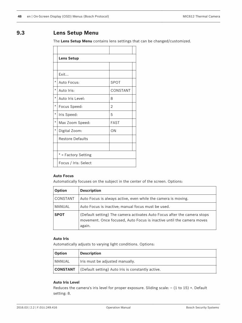
Lens Setup MenuThe Lens Setup Menu contains lens settings that can be changed/customized.
Lens Setup
Exit...
* Auto Focus: SPOT
* Auto Iris: CONSTANT
* Auto Iris Level: 8
* Focus Speed: 2
* Iris Speed: 5
* Max Zoom Speed: FAST
* Digital Zoom: ON
Restore Defaults
* = Factory Setting
Focus / Iris: Select
Auto FocusAutomatically focuses on the subject in the center of the screen. Options:
Option Description
CONSTANT Auto Focus is always active, even while the camera is moving.
MANUAL Auto Focus is inactive; manual focus must be used.
SPOT (Default setting) The camera activates Auto Focus after the camera stopsmovement. Once focused, Auto Focus is inactive until the camera movesagain.
Auto IrisAutomatically adjusts to varying light conditions. Options:
Option Description
MANUAL Iris must be adjusted manually.
CONSTANT (Default setting) Auto Iris is constantly active.
Auto Iris LevelReduces the camera's iris level for proper exposure. Sliding scale: – (1 to 15) +. Defaultsetting: 8.
9.3
48 en | On-Screen Display (OSD) Menus (Bosch Protocol) MIC612 Thermal Camera
2016.03 | 2.2 | F.01U.249.416 Operation Manual Bosch Security Systems

Focus SpeedAdjusts the manual focus speed. Sliding scale: – (1 to 15) +. Default setting: 2. Iris SpeedAdjusts the manual iris speed. Sliding scale: – (1 to 10) +. Default setting: 5. Max. Zoom SpeedAdjusts the manual zoom speed. Options: SLOW, MEDIUM, FAST (default setting). Digital ZoomEnables or disables digital zoom. Options: ON (default setting), OFF.
MIC612 Thermal Camera On-Screen Display (OSD) Menus (Bosch Protocol) | en 49
Bosch Security Systems Operation Manual 2016.03 | 2.2 | F.01U.249.416

PTZ Setup MenuThe PTZ Setup Menu contains pan/tilt/zoom settings that can be changed/customized.
PTZ Setup
Exit...
* Autopan: 30 deg/sec
* Tour 1 Period: 5 sec
* Tour 2 Period: 5 sec
* PTZ Fixed Speed: 4
* Inactivity: OFF
* Inact. Period: 2 min
* Autopivot: ON
* Orientation NORMAL
* Freeze Frame onPreposition
ON
Tilt Up Limit...
Azimuth Zero...
Restore Defaults...
* = Factory Setting
Focus/Iris: Select
AutoPanAdjusts speed of camera during AutoPan and AutoScan. Sliding scale: –(1º/sec. to 60º/sec.)+.Default setting: 30°/sec. Tour 1 PeriodChanges dwell time between presets during the tour. Sliding scale: –(3 sec. to 10 min.)+.Default setting: 5 sec. Tour 2 PeriodChanges dwell time between presets during the tour. Sliding scale: –(3 sec. to 10 min.)+.Default setting: 5 sec. PTZ Fixed SpeedSets pan and tilt speed when controlled by a fixed speed controller. Sliding scale: –(1 to 15)+.Default setting: 4.
9.4
50 en | On-Screen Display (OSD) Menus (Bosch Protocol) MIC612 Thermal Camera
2016.03 | 2.2 | F.01U.249.416 Operation Manual Bosch Security Systems

InactivitySelects the mode to which the camera reverts after the period of inactivity set in the inactivityperiod. Options:
Option Description
Scene 1 Returns to Preset 1.
Prev Aux Returns to previous activity, such as Aux commands 1, 2, 7, 8, 50,or 52.
OFF (Default setting) Remains on the current scene indefinitely.
Inact. PeriodSets the time period of inactivity before the above action occurs.Sliding scale: – (3 sec. to 10 min.) +. Default setting: 2 min. AutopivotAutomatically rotates the camera 180º when following a subject traveling directly beneath thecamera. Options: ON (default setting), OFF. OrientationSelects mounting options. Options:
Option Description
NORMAL (Default setting) The camera is straight, upright; the software doesnot rotate the view.
INVERTED The sofware rotates the video 180º automatically.
Freeze Frame On PrepositionHolds a preposition video frame while moving to another preposition. Options: ON (defaultsetting), OFF. Tilt Up Limit...Sets the upper tilt limit of the camera. Use the joystick to move to a scene. Azimuth Zero...Sets the zero degree pan position. Use the joystick to move to a scene that you want to set asthe zero degree pan position and as the North compass heading. For more details, refer toAzimuth, Elevation, and Compass Directions, page 80.
MIC612 Thermal Camera On-Screen Display (OSD) Menus (Bosch Protocol) | en 51
Bosch Security Systems Operation Manual 2016.03 | 2.2 | F.01U.249.416

Display Setup MenuThe Display Setup Menu contains display settings that can be changed/customized.
Display Setup
Exit...
* Title OSD: MOMENTARY
* Camera OSD: ON
Display Adjust
* Azimuth: OFF
* Compass: OFF
Sector Blanking...
Privacy Masking...
Edit Sector Title...
Edit Scene Title...
Restore Defaults...
* = Factory Setting
Focus / Iris: Select
Title OSDControls how the OSD displays sector or shot titles. Options:
Option Description
OFF Titles are hidden.
ON Titles are displayed continuously.
MOMENTARY (Default setting) Titles are displayed for a few seconds, then disappear fromthe screen.
Camera OSDControls how the OSD displays camera response information, such as Digital Zoom, Iris open/close, and Focus near/far. Options: ON (default setting), OFF. Display AdjustAdjusts the text brightness and vertical position of the on-screen title. Options:
9.5
52 en | On-Screen Display (OSD) Menus (Bosch Protocol) MIC612 Thermal Camera
2016.03 | 2.2 | F.01U.249.416 Operation Manual Bosch Security Systems

Option Description
Up Moves screen title up.
Down Moves screen title down.
Brighter Brightens the intensity of the on-screen text.
Darker Darkens the intensity of the on-screen text.
AzimuthDisplay azimuth/elevation values. Options: ON, OFF (default setting). For more details, refer toAzimuth, Elevation, and Compass Directions, page 80. CompassDisplays compass heading. Options: ON, OFF (default setting). For more details, refer toAzimuth, Elevation, and Compass Directions, page 80. Sector BlankingAllows video blanking of selected sectors. Press Focus/Iris to blank or clear a sector (1through 16). Follow the on-screen instructions. Privacy MaskingAllows masking of sensitive areas. Select option Mask and follow the on-screen instructions toset a mask for up to 24 privacy masks are available, with a maximum limit of eight (8) to ascene. For more details, refer to Privacy Masking, page 79. Edit Sector TitleAllows editing of existing Sector (Zone) Titles. Select a sector title to access the characterpalette. For instructions, refer to Specifying a Shot or a Sector Title. Edit Scene TitleAllows editing existing Scene (Shot) Titles. Select a scene title, and then select a menuoption:– Edit Scene Title to access the character palette. For instructions, refer to Specifying a
Shot or a Sector Title.– Clear Scene to delete the selected scene title.
MIC612 Thermal Camera On-Screen Display (OSD) Menus (Bosch Protocol) | en 53
Bosch Security Systems Operation Manual 2016.03 | 2.2 | F.01U.249.416

Communication Setup MenuThe Communication Setup Menu contains baud rate and Bilinx control settings.
Communication Setup
Exit...
* AutoBaud: ON
* Baud Rate: 9600
Bilinx
Restore Defaults
* = Factory Setting
Focus / Iris: Select
AutoBaudTurns on AutoBaud detection, which detects and adjusts the camera protocol and baud rate tomatch that of the controller. Options: ON (default setting), OFF. ON automatically acceptsbaud rates from 2400 to 57600.Note: If stepping from 2400 to 57600 baud, you must first set the Baud Rate to 19200 forAutoBaud to detect the higher baud rate. Baud RateManually sets the baud rate when AutoBaud is set to OFF. Options are 2400, 4800, 9600(default setting), 19200, 38400, and 57600. BilinxActivates Bilinx control communication. (Only available when not connected to a Bilinx datainterface unit.) Options: ON (default setting), OFF.
9.6
54 en | On-Screen Display (OSD) Menus (Bosch Protocol) MIC612 Thermal Camera
2016.03 | 2.2 | F.01U.249.416 Operation Manual Bosch Security Systems

Alarm SetupThe Alarm Setup Menu contains alarm inputs, outputs and rules.
Notice!
The maximum number of Alarm Inputs is eight (8), available only on the Alarm and Washer
Pump Drive Card (MIC-ALM) (sold separately). This card is available for non-IR power supply
units (PSUs) only. IR models only will show Alarm Inputs 1–4 and numbers 5–12 will display
NONE. See Layout of MIC-240PSU-2 and MIC-115PSU-2, page 17 for the specific number of
alarm Inputs and Outputs per PSU.
Alarm Setup Inputs Setup
Exit... Exit...
Multi Alarm Setup 1. Alarm Input 1 N.O.
Inputs Setup... 2. Alarm Input 2 N.O.
Outputs Setup... 3. Alarm Input 3 N.O.
Rule Setup... 4. Alarm Input 4 N.O.
RestoreDefaults...
5. Alarm Input 5 N.O.
6. Alarm Input 6 N.O.
7. Alarm Input 7 N.O.
8. Alarm Input 8 N.O.
9. NONE
10. NONE
12. NONE
12. NONE
Focus / Iris: Select Type
Focus / Iris: Select Right / Left: Select Mode
9.7
MIC612 Thermal Camera On-Screen Display (OSD) Menus (Bosch Protocol) | en 55
Bosch Security Systems Operation Manual 2016.03 | 2.2 | F.01U.249.416

Multi Alarm SetupAllows setup of multiple alarms. Options: On; Off. Checkbox button to "Select." Inputs Setup Submenu Choices: Inputs SetupDefines physical inputs or events and commands that can be used in a rule. There are twelve(12) alarm inputs available. Inputs 1-8Defines the type of physical input (dry contact): N.O. (Normally Open) (default setting) or N.C.(Normally closed).Inputs 1–4 are available for Standard and IR models.Inputs 5–8 are available for Standard models with optional alarm card installed. Inputs 9-12Defines input commands that can be used in a rule. Command inputs can also be customizedby using non-assigned keyboard command numbers.
Option Description
NONE (Default setting) No command defined.
Aux On Responds to a standard or custom keyboard ON (1-99) command.
Aux Off Responds to a standard or custom keyboard OFF (1-99)command.
Shot Responds to a Preset shot or scene from 1-99.
On models with the 35 mm thermal lens, you can also select either High Temp Thermal Meteror Low Temp Thermal Meter, to trigger an alarm on the OSD if the thermal spot meteridentifies that the temperature of an object in the view of the camera is outside of thetemperature threshold set in the system. By default, the option is "Not Set." For more details,see Section 8.4 Triggering Alarms On Detection of Objects Outside of Set Thermal TemperatureThreshold, page 58.
56 en | On-Screen Display (OSD) Menus (Bosch Protocol) MIC612 Thermal Camera
2016.03 | 2.2 | F.01U.249.416 Operation Manual Bosch Security Systems

Outputs Setup Submenu
Outputs Setup...
Exit...
1. NONE
2. NONE
3. NONE
4. NONE
5. NONE
6. NONE
7. NONE
8. NONE
9. NONE
10. NONE
11. NONE
12. NONE
Focus / Iris: Select Type
Right / Left: Select Mode
MIC612 Thermal Camera On-Screen Display (OSD) Menus (Bosch Protocol) | en 57
Bosch Security Systems Operation Manual 2016.03 | 2.2 | F.01U.249.416

Outputs Setup Submenu Choices: Outputs SetupDefines physical outputs and keyboard commands for use in a rule. Outputs 1–2Defines a physical output: N.O. (Normally Open circuit) (default setting) or N.C. (Normallyclosed circuit). Outputs 3–12Defines a command output for use in a rule.
Option Description
None (Default setting) No command defined.
Aux On Responds to a keyboard ON command.
Aux Off Responds to a keyboard OFF command.
Shot Responds to a Preset shot.
OSD Displays the output on the on-screen display.
Transmit Transmits a message back to the head end (available with RS-232 serial andBilinx connections).
NONE (Default setting) No command defined.
58 en | On-Screen Display (OSD) Menus (Bosch Protocol) MIC612 Thermal Camera
2016.03 | 2.2 | F.01U.249.416 Operation Manual Bosch Security Systems

Rule Setup Submenu
Notice!
You can program a total of twelve rules. You must define the inputs and outputs before you
program a rule. See Alarm Setup, page 55, to configure alarm inputs and outputs.
Rule Setup... Rule 1
Exit... Exit...
1. Rule 1 Enabled Enabled YES
2. Rule 2 Disabled Input:
3. Rule 3 Invalid NONE
4. Rule 4 Empty NONE
5. Rule 5 Empty NONE
6. Rule 6 Empty
7. Rule 7 Empty Output:
8. Rule 8 Empty OSD
9. Rule 9 Empty Shot 2
10. Rule 10 Empty Alarm Relay 2 sec
11. Rule 11 Empty NONE
12. Rule 12 Empty
Right / Left: Select Period Time
Focus / Iris: Select Focus / Iris: Select Type
MIC612 Thermal Camera On-Screen Display (OSD) Menus (Bosch Protocol) | en 59
Bosch Security Systems Operation Manual 2016.03 | 2.2 | F.01U.249.416

Rule Setup Submenu Choices: Rule Setup Displays the status of rules and lets you add new rules or modify an existing rule.Rule 1-12 Displays the status of a rule on the right side of the menu. Rule status options:
Option Description
Enabled The rule inputs and outputs are properly defined and the ruleis turned on.
Disabled The rule inputs and outputs are defined but the rule is turnedoff.
Invalid The rule has a missing or invalid input or output.
Empty (Default setting) The rule has no inputs or outputs defined.
Selecting a Rule number provides access to its configuration menu. The Rule # Menu allowsyou to configure a rule from previously-defined alarm inputs and outputs. Once an alarm isconfigured with valid inputs and outputs, it can be turned on or off (enabled or disabled)through its configuration menu. Rule # Choices:Enabled Turns the rule on or off after its inputs and outputs have been defined. YES to enable or NO todisable (default setting).Input Toggles through a list of valid inputs set in the Alarm I/O Setup > Inputs Setup Menu thatdefines the rule's inputs. A rule can have up to four (4) inputs.Inputs which were set in the Inputs Setup Menu include Aux On/Off (1–99), Shot, and NONE(default setting).Output Toggles through a list of valid outputs set in the Alarm I/O Setup > Outputs Setup Menu thatdefines a rule's outputs.Outputs set in the Outputs Setup Menu include Alarm Relay, Aux On/Off (1–9), Shot, OSD,Transmit, and NONE (default setting).Some outputs, such as Alarm Outputs 1–2 and Aux On/Off can be set to be active for aspecific duration of time as follows:Seconds: 1–5, 10, 15, or 30Minutes: 1–5 or 10Latched: The alarm stays active until acknowledged.Follows: The alarm follows the alarm rule.Default setting: NONE
Notice!
You can include up to four (4) Input and Output events in a single rule. Each input and
output, however, must be true for the alarm's rule to be valid and enabled.
60 en | On-Screen Display (OSD) Menus (Bosch Protocol) MIC612 Thermal Camera
2016.03 | 2.2 | F.01U.249.416 Operation Manual Bosch Security Systems

Language MenuThe Language Menu contains a list of languages in which the on-screen menus are available.
Language
Exit...
English
Spanish
French
German
Portuguese
Polish
Italian
Dutch
Russian
Czech
Focus / Iris: Save and Exit
9.8
MIC612 Thermal Camera On-Screen Display (OSD) Menus (Bosch Protocol) | en 61
Bosch Security Systems Operation Manual 2016.03 | 2.2 | F.01U.249.416

Diagnostics MenuThe Diagnostics menu contains a list of diagnostic tools and events. Most of these menu itemsare display items only; you cannot select different values to change.
Diagnostics
Exit...
Alarm Status...
BIST...
Internal Temp: Deg F / Deg C
High Temp Events: Deg F / Deg C
Highest Temp Deg F / Deg C
Low Temp Events: Deg F / Deg C
Lowest Temp: Deg F / Deg C
Internal Humidity %
Humidity Events 0
Security Access: 0
CTFID Access: 0
Restart Events:
Power-up Events: 0
Low-Volt Events: 0
Video Loss Events: 0
Total Time On 0hr 0min
Thermal Camera TestPattern
On/Off
Focus / Iris: Save and Exit
Alarm StatusEnters the Alarm Status menu and displays the real time status of alarm inputs and outputs.Alarm Inputs 1 to 8, Alarm Outputs 1 to 2 (Closed or Open) BISTEnters the Perform Built-in Self Tests menu. YES to start test. If confirmed, the BIST testsstart and the results are displayed. Typical results are:Data Flash: PASSFPGA: PASSBilinx: PASS
9.9
62 en | On-Screen Display (OSD) Menus (Bosch Protocol) MIC612 Thermal Camera
2016.03 | 2.2 | F.01U.249.416 Operation Manual Bosch Security Systems
Internal Temp.Displays the current temperature of the camera, in degress Fahrenheit and in degrees Celsius. High Temp EventsDisplays the number of times that the threshold of high temperature was exceeded. Highest TempDisplays the highest temperature reached, in degrees Fahrenheit and in degress Celsius. Low Temp EventsDisplays the number of times that the threshold of low temperature was exceeded. Lowest TempDisplays the lowest temperature reached, in degrees Fahrenheit and in degress Celsius. Internal HumidityDisplays the percentage of humidity inside the camera housing. Humidity EventsDisplays the number of times that the threshold of the humidity inside the camera housingwas exceeded. Security AccessDisplays the number of times that the locked-command menu is unlocked. CTFID AccessDisplays the number of times that the Configuration Tool is accessed. Restart EventsDisplays the number of restart events. Power Up EventsDisplays the number of power up events. Low Volt EventsDisplays the number of times that the camera dropped below the acceptable voltage limit. Video Loss EventsDisplays the number of time that video was lost.Thermal Camera Test PatternActivates the test pattern mode to verify electronics (the output of the digital data channel)for the thermal camera.
MIC612 Thermal Camera On-Screen Display (OSD) Menus (Bosch Protocol) | en 63
Bosch Security Systems Operation Manual 2016.03 | 2.2 | F.01U.249.416

Option Description
Off (Default setting) No test pattern is available.
Ascending ramp A test pattern appears in the analog and digital data channels, toallow you verify the output of the digital data channel.The figure below is a horizontal slice of the complete image; thepattern repeats 19 times in the complete image.When displayed on an analog video monitor, and if the AGC modeis not set to the default value, the pattern may appear differentlythan shown here.
Slice of complete image (320 x 256 or 640 × 512)– 1: (0,0) = 0– 2: (639,0) = 639– 3: (25,408) (320 models)/(383,25) (640 models) = 16383– 4: (25,409) (320 models)/(384,25) (604 models) = 0
Vertical .
Color bars
Notice!
Before activating the test pattern, turn off the correction terms and set the AGC Mode to
Outdoor. This mode will not persist over a power cycle.
Total Time OnDisplays the total time that the video has been on.Alarm Status SubmenuThis menu displays the status of the alarm inputs and outputs.The Alarm Status submenu appears differently depending upon the Multi-Alarm setting.
Alarm Status
Exit...
Alarm Input 1 Open
Alarm Input 2 Open
Alarm Input 3 Open
Alarm Input 4 Open
Alarm Input 5 Open
64 en | On-Screen Display (OSD) Menus (Bosch Protocol) MIC612 Thermal Camera
2016.03 | 2.2 | F.01U.249.416 Operation Manual Bosch Security Systems

Alarm Status
Alarm Input 6 Open
Alarm Input 7 Open
Alarm Input 8 Open
Alarm Output 1 Open
Focus / Iris: Save and Exit
Alarm Input 1...8Displays the status of alarm inputs 1 through 7.HighLowOpen (Normally Open)Closed (Normally Closed) Alarm OutputDisplays the status of the alarm output.
MIC612 Thermal Camera On-Screen Display (OSD) Menus (Bosch Protocol) | en 65
Bosch Security Systems Operation Manual 2016.03 | 2.2 | F.01U.249.416

On-Screen Display (OSD) Menus (Pelco Protocol)This chapter identifies and describes each OSD menu option, as well as the default setting foreach option, for Pelco protocol. For step-by-step instructions, see Common User Commands,page 76 and Advanced Features, page 78.To open the main Setup Menu in Pelco protocol: Press 95-PRESET for approximately 2seconds. The screen Setup Menu appears.
Setup Menu
Exit...
Command Lock: OFF
Bosch Menu
Camera Setup
PTZ Setup
Edit Password
*FastAddress: Not Set
Advanced
Software Version
Ack and Reset Alarms
Restore All Settings
Reset All Memory
* = Factory Setting
Focus / Iris: Select
10
66 en | On-Screen Display (OSD) Menus (Pelco Protocol) MIC612 Thermal Camera
2016.03 | 2.2 | F.01U.249.416 Operation Manual Bosch Security Systems

Setup Menu Choices:
Menu Description
Exit Exits the menu.
Command Lock Allows or prohibits accessing locked commands. (If password isset, you are prompted to enter the password. The default setting isON.
Bosch Menu Accesses the full configuration menu and all camera settings.
Camera Setup Accesses adjustable camera settings such as White Balance andNight Mode.
PTZ Setup Accesses adjustable pan/tilt/zoom (PTZ) settings such as tours,scan speed, edit presets, limit stops, recording, and AutoPivotsettings.
Edit Password Changes the password.
FastAddress Sets or changes a camera address.
Advanced
Software Version Displays the current software versions.
Ack and Reset Alarms Acknowledges and resets active alarms.
Restore All Settings Restores all settings to their original default setting.
Reset All Memory Clears all settings, including scene shots, tours, and recordingsstored in the camera memory.
Notice!
If commands are locked and you press Focus or Iris, the camera displays the on-screen
message: “Command is Locked.”
MIC612 Thermal Camera On-Screen Display (OSD) Menus (Pelco Protocol) | en 67
Bosch Security Systems Operation Manual 2016.03 | 2.2 | F.01U.249.416

Bosch MenuThe Bosch Menu allows full access to the main Setup Menu and all camera configurationsettings.
Pelco menu Bosch menu
Setup Menu Setup Menu
Exit...
Command Lock: OFF Exit...
Bosch Menu Camera Setup
Camera Setup Lens Setup
PTZ Setup PTZ Setup
Edit Password Display Setup
*FastAddress: Not Set CommunicationSetup
Advanced Alarm Setup
Software Version Language
Ack and Reset Alarms Advanced
Restore All Settings Diagnostics
Reset All Memory
* = Factory Setting
Focus / Iris: Select Focus / Iris: Select
Refer to On-Screen Display (OSD) Menus (Bosch Protocol), page 42 for a complete descriptionof Bosch menus and configuration settings.
10.1
68 en | On-Screen Display (OSD) Menus (Pelco Protocol) MIC612 Thermal Camera
2016.03 | 2.2 | F.01U.249.416 Operation Manual Bosch Security Systems

Camera SetupThe Pelco Camera Setup Menu provides access to camera settings.
Camera Setup
Exit...
* White Bal: OUTDOOR
* Night Mode: AUTO
* Wiper CONTINUOUS
* = Factory Setting
Focus / Iris: Select
Camera Setup Menu Choices:
Menu Description Sub-menu / Description DefaultSetting
Exit Exits the menu.�
WhiteBalance
Sets a default value incase the Pelcocontroller disables thewhite balance.
OUTDOOR: Sets a default setting ifthe controller disables whitebalance.INDOOR: Sets a default setting ifthe controller disables whitebalance.
OUTDOOR
Night Mode Switches from color tomonochrome.
ON: Sets Night Mode on.OFF: Sets Night Mode off.AUTO: Sets Night Mode to Auto set.
ON (Day/Nightmodels only)
Wiper ON/OFF: Activates/deactivates theselected wiper mode, respectively.CONTINUOUS: Wiper wipescontinuously until deactivatedmanually or by the five-minute time-out built in to the system.INTERMITTENT: Wipes twice, thenturns off after 15 seconds.ONE SHOT: Wipes five times, thenturns off.WASH WIPE: Wiper washes andwipes.
Continuous
10.2
MIC612 Thermal Camera On-Screen Display (OSD) Menus (Pelco Protocol) | en 69
Bosch Security Systems Operation Manual 2016.03 | 2.2 | F.01U.249.416

PTZ SetupThe Pelco PTZ Setup Menu provides access to the PTZ settings such as tours, scan speed,presets, limit stops, recording, and AutoPivot.
PTZ Setup
Exit...
* Edit Tour 1...
* Edit Tour 2...
* Tour 1 Period: 5 sec
* Tour 2 Period: 5 sec
* Scan Speed 30 deg/sec
Edit Presets...
* Limit Stops: OFF
* Recording: “A”
* Autopivot: ON
* = Factory Setting
Focus / Iris: Select
10.3
70 en | On-Screen Display (OSD) Menus (Pelco Protocol) MIC612 Thermal Camera
2016.03 | 2.2 | F.01U.249.416 Operation Manual Bosch Security Systems

PTZ Setup Menu Choices:
Menu Description Sub-menu / Description DefaultSetting
Exit Exits the menu.
Edit Tour 1 Accesses the Add /Remove Scenes OnStandard Tour 1 Menu.
Exit: Exits the menu.Scene (1 - 5): Adds or removesscenes from the Standard Tour.
Edit Tour 2 Accesses the Edit CustomTour Menu.
Exit: Exits the menu.Scene (1 - 5): Adds or removesscenes from the Custom Tour.
Tour 1 Period Changes the length ofwaiting time betweenpresets.
Sliding scale: – (3 sec. to 10 min.) + 5 sec.
Tour 2 Period Changes the length ofwaiting time betweenpresets.
Sliding scale: – (3 sec. to 10 min.) + 5 sec.
Scan Speed Changes the Autopan andAutoScan speeds.
Sliding scale: – (1°/sec to 60°/sec)+
30°/sec.
Edit Presets Modifies preset scenes. 1-99 scenes
Limit Stops Toggles the Limit Stops forAutoScan.
ON or OFF OFF
Recordings Selects record Pattern 1 or2, if normal patterncommand does notrespond.
“A” or “B” “A”
AutoPivot Follows a subject whilebeneath the camera,without inverting thepicture.
ON or OFF ON
MIC612 Thermal Camera On-Screen Display (OSD) Menus (Pelco Protocol) | en 71
Bosch Security Systems Operation Manual 2016.03 | 2.2 | F.01U.249.416

AUX Setup MenuThe AUX Setup menu provides an area to remain Aux commands.
AUX Setup
Exit...
* WASH WIPE
* Alarm Output 2:
* Not Set
Not Set
Not Set
Not Set
* = Factory Setting
Focus / Iris: Select
10.4
72 en | On-Screen Display (OSD) Menus (Pelco Protocol) MIC612 Thermal Camera
2016.03 | 2.2 | F.01U.249.416 Operation Manual Bosch Security Systems

Other Menus
Menu Description DefaultSetting
Edit Password Sets or displays the password. See Setting Passwords,page 37.
FastAddress Sets or changes the address. Not Set
Software Version Displays the camera software version.
Ack and Reset Alarms Acknowledges and resets alarms. If there is no activealarm input, the OSD displays the following message:“No Active Alarms.”
Restore All Settings Restores all settings to their original factory defaultsettings.
Reset All Memory Restores all settings to their original factory defaultsettings and clears all user programmed settings suchas preset scenes and recordings.
10.5
MIC612 Thermal Camera On-Screen Display (OSD) Menus (Pelco Protocol) | en 73
Bosch Security Systems Operation Manual 2016.03 | 2.2 | F.01U.249.416

Operation of the Thermal Camera
Switching VideoTo switch Video Channel 2 between the optical (visible) camera and the thermal camera, enterthe Thermal Camera Setup menu of the OSD, select the option Second Channel Video, andthen toggle to the appropriate choice.
Flat-Field Correction (FFC)The thermal camera uses an internal process called flat-field correction (FFC) to improve thequality of the thermal video image displayed on the monitor. During this process, a shutterrotates in front of the Focal Plane Array (FPA) to give a uniform temperature (a flat field) toevery detector element. During the process (which takes less than a second), the live thermalvideo image is frozen, and persists, while the camera updates correction coefficients. After theprocess completes, live video returns automatically. With a more uniform array output, thequality of the image should improve. About 2 seconds before an automatic FFC operation, the thermal camera displays a smallgreen square in the upper right of the video output. This square symbol is called the Flat FieldImminent Symbol; it warns that FFC is about to begin.
Figure 11.1: Thermal image with Flat Field Imminent Symbol (green square)
Performing FFC often should prevent the thermal video image from appearing “grainy”. This isespecially important when the temperature of the camera is fluctuating, such as immediatelyafter the camera is powered on, or when ambient temperature is changing.
Displaying Thermal Camera TemperatureThe thermal camera can display its internal temperature on the video output with a SPOTmeter (320 TVL models only).1. In Bosch protocol, in the OSD, enter "Aux ON + 463 + ENTER." The message, "SPOT meter
Display: ON" should appear on-screen, and the SPOT meter should appear. Note: entering "Aux OFF + 463 +ENTER" deactivates the SPOT meter.
2. Select the appropriate temperature scale. Enter "Aux ON + 463 + ENTER" again to togglethe temperature scale as necessary. (The default scale is in Degrees F.)
Notice!
The selected settings should remain in internal memory; if you must turn off power to the
camera, the camera should retain the last meter display and the temperature scale (°F/°C);
those should appear after power on.
11
11.1
11.2
11.3
74 en | Operation of the Thermal Camera MIC612 Thermal Camera
2016.03 | 2.2 | F.01U.249.416 Operation Manual Bosch Security Systems

Triggering Alarms On Detection of Objects Outside of SetThermal Temperature ThresholdOn models with the 35 mm thermal lens, you can set a High Temp Thermal Meter or Low TempThermal Meter in order to trigger an alarm if the thermal spot meter identifies that thetemperature of an object in the view of the camera is outside of the temperature threshold setin the system. The alarm input "High Temp Thermal Meter" identifies the high temperaturethreshold for objects in view of the camera. If the camera detects an object with atemperature that is higher than the threshold that is set in the system, it triggers an alarm.The alarm input "Low Temp Thermal Meter" identifies the low temperature threshold forobjects in view of the camera. If the camera detects an object with a temperature that is lowerthan the threshold that is set in the system, it triggers an alarm. For both inputs, thetemperature range is -40 °C to +150 °C, in 1 degree increments. The temperature scale is indegrees Celsius only. The system allows you to set multiple high and low temperature inputs.You can also set only a High threshold, or only a Low threshold; you do not need to set both. To trigger the alarm, you must set the temperature threshold (high or low or both), and thenset the alarm rule.Set the High Temperature ThresholdTo set the High Temp Thermal Meter input, follow these steps:1. Access the Alarm Setup menu of the OSD.2. Select the Inputs Setup submenu.3. Select the number of the input that you want to set.4. Select the value "High Temp Thermal Meter".5. Select the degree for the high temperature threshold (for example, 50 °C). The default
option is "Not Set."6. Exit the Inputs Setup submenu. The High Temperature threshold is now set.Set the Low Temperature ThresholdTo set the Low Temp Thermal Meter input, follow these steps:1. Access the Alarm Setup menu of the OSD.2. Select the Inputs Setup submenu.3. Select the number of the input that you want to set.4. Select the value "Low Temp Thermal Meter".5. Select the degree for the low temperature threshold (for example, -10 °C). The default
option is "Not Set."6. Exit the Inputs Setup submenu. The Low Temperature threshold is now set.Set the Alarm RuleTo set the rule for the thermal temperature alarm, follow these steps:1. Access the Rule Setup submenu.2. Select the number of the rule that you want to define.3. Select "Input."4. Select the appropriate Input value: "High Temp Thermal Meter" or "Low Temp Thermal
Meter".5. Select "Output."6. Select the appropriate Output value. For example, in order to display the thermal
temperature alarm, when triggered, on the OSD, select the value "OSD."7. Select "Yes" when prompted to "Enable Rule" in order to activate the alarm rule.8. Exit the Rule [number] submenu. The rule that you selected is now "Enabled" in the Alarm
I/O Setup Menu.
11.4
MIC612 Thermal Camera Operation of the Thermal Camera | en 75
Bosch Security Systems Operation Manual 2016.03 | 2.2 | F.01U.249.416

Common User Commands
Configuring Preposition ToursA Preposition Tour automatically moves the camera through a series of preset or saved shots.The MIC camera has one (1) standard preset tour and one (1) customized preset tour. Tour 1is a standard tour that moves the camera through a series of shots in the sequence that theywere set. Tour 2 is a custom tour that allows you to change the sequence of shots in the tourby inserting and deleting scenes.
To start Preposition Tour 1:1. Set a series of preset shots in the order that you want the MIC camera to cycle through.2. Press ON-8-ENTER to start the tour. The tour then cycles through the series of shots until
it is stopped.
To stop a Preposition Tour:4 Press OFF-8-ENTER or move the joystick to stop either type of tour.
To add or remove scenes to Preposition Tour 1:1. Press SHOT-900-ENTER to access the Add/Remove Scenes Menu.2. Use the Focus/Iris buttons to add or remove the selected scene from the tour.
To start custom Preposition Tour 2:4 Press ON-7-ENTER to start a tour. The tour cycles through the series of shots (in the
order that they were defined) until it is stopped.
To edit a custom Preposition Tour 2:1. Press SET-900-ENTER to access the Add/Remove Menu.2. Press the Focus/Iris buttons to add or remove the selected scene.
To change the dwell period of a tour:1. Press ON-15-ENTER to access the Tour Period Menu.2. Select the tour (Tour 1 or Tour 2) and follow the on-screen instructions.
Recording ToursThe MIC camera can make up to two (2) recorded tours. A Recorded Tour saves all manualcamera movements made during the recording, including its rate of pan, tilt and zoom speedsand other lens setting changes.
To Record Tour A:1. Press ON-100-ENTER to start recording a tour.2. Press OFF-100-ENTER to stop recording.
To play back Recorded Tour A:1. Press ON-50-ENTER to begin continuous playback.2. Press OFF-50-ENTER or move the joystick to stop playback.
To Record Tour B:1. Press ON-101-ENTER to start recording the tour.2. Press OFF-101-ENTER to stop the tour.
To play back Recorded Tour B:1. Press ON-52-ENTER to begin continuous playback.2. Press OFF-52-ENTER or move the joystick to stop playback.
12
12.1
12.2
76 en | Common User Commands MIC612 Thermal Camera
2016.03 | 2.2 | F.01U.249.416 Operation Manual Bosch Security Systems

Using the Wiper/Washer (Bosch Protocol)The "predefined position" for the wash/wipe function is preset 62. The installer must definepreset 62 (preferably where the washer nozzle is located and can direct washer fluid towardsthe camera window) before using the wiper/washer function.
To activate the washer/wiper function, press ON-105-ENTER, and then confirm thissequence:1. The wiper moves to a predefined position.2. The washer turns on for five seconds. Simultaneously, the wiper turns on and wipes five
times.3. The washer turns off. The wiper continues wiping for five more wipes as the camera
returns to its initial PTZ position (and to inactive mode if applicable).4. The wiper turns off.
To activate intermittent wipe:Press ON-103-ENTER. The wiper wipes twice, then returns to parked position, and then turnsoff 15 seconds later. This sequence will continue for up to 5 minutes or until an OFF-103-ENTER command is sent.
To activate continuous wipe:Press ON-102-ENTER. The wiper wipes continuously for up to 5 minutes, or until anotherOFF-102-ENTER command is sent (if the command is sent before the 5 minutes elapse). Thewiper then turns off automatically.
To activate the wiper to wipe five (5) times:Press ON-104-ENTER. The wiper wipes five (5) times, or until an OFF-104-ENTER command issent (if the command is sent before the wiper wipes five (5) times), then returns to parkedposition and turns off.
12.3
MIC612 Thermal Camera Common User Commands | en 77
Bosch Security Systems Operation Manual 2016.03 | 2.2 | F.01U.249.416

Advanced FeaturesThis chapter details advanced user commands, which are more complicated than those inCommon User Commands, page 76.
Alarm RulesMIC cameras feature a powerful alarm rule engine. In its simplest form, an alarm rule definesthose inputs that activate specific outputs. In its more complex form, a rule can beprogrammed to take any combination of inputs and keyboard commands to perform a camerafunction. There are numerous combinations of alarm inputs and outputs that can beprogrammed into twelve (12) alarm rules.
Controlling Alarm RulesThe AUX 69 command allows a user to enable or disable all alarm rules. By default, alarm rulesare enabled until the OFF-69-ENTER command is issued from a keyboard (there is nocorresponding menu item for this command). Disabling alarms rules does not erase the rule,the MIC camera preserves the user-defined settings and the rule data is restored when theON-69-ENTER command is issued.The OFF-69-ENTER command performs the following actions:– Disables all alarm rules– Displays the message “Ack and Reset Alarms” if an alarm-rule triggered alarm is active
when the camera receives the disable command. You must acknowledge the alarm beforethe rule is disabled.
– Prevents the modification of an alarm rule while disabled.
Alarm Rule ExamplesFollowing are two examples for setting up alarm rules.Example 1: Basic Alarm RuleScenario: We want a door alarm contact to:1. Flash an OSD message (***ALARM 1***) on the display when the alarm is triggered.2. Move the MIC camera to a saved position. (For this example, Shot 7.)3. Transmit a Bilinx signal over the coax cable to the head-end system, such as an Allegiant,
to trigger an alarm response.The sequence to program the above alarm rule example is as follows:1. Wire the door contact to Input 1 in the camera. This circuit is normally open.2. Define the Alarm Input(s): From the Inputs Setup menu, ensure that Alarm Input 1 is set
to N.O. (the default setting for Input 1).3. Define the Alarm Outputs:
From the Outputs Setup menu, ensure that Output 5 is set to OSD (the default settingfor Output 5).Set Output 6 to Shot 7.Set Output 7 to Transmit (a Bilinx signal to the head end).
4. Set up the Alarm Rule by selecting the Inputs and Outputs from the Rule Setup menu:Select Rule 1.Set the first input to Alarm Input 1.Set the first output to OSD.Set the second output to Shot 7.Set the third output to Transmit.
5. Enable the Alarm Rule: Highlight Enabled and select YES.
13
13.1
13.1.1
13.1.2
78 en | Advanced Features MIC612 Thermal Camera
2016.03 | 2.2 | F.01U.249.416 Operation Manual Bosch Security Systems
Example 2: Advanced Alarm RuleScenario: A MIC camera located at an airport is set to AutoPan Between Limits from theparking garage to the airport terminal. The gate entering the airport has an alarm contactconnected to the camera, and the perimeter fence in the area of the gate has an infrared (IR)sensor for motion detection (motion detector) that is connected to the camera.When the alarms for the gate contact and the motion detector are activated at the same time,we want the alarm rule to:1. Flash an OSD message (***ALARM 2***) on the monitor.2. Stop the AutoPan and move the camera to a saved position (Shot 5) viewing the fence.3. Transmit a Bilinx signal to the head end system to trigger an alarm response.The sequence to program this alarm rule example is as follows:1. Wire and set the alarm Input(s).
– Wire the motion detector to Input 1. (This circuit is normally open.)– Wire the gate alarm contact to Input 5. (This circuit is normally closed.)
2. From the Inputs Setup menu:– Ensure that Input 1 (the motion detector) is set to N.O. (This setting is the default
for Input 1.)– Ensure that Input 5 (the gate contact) is set to N.C.
3. Set the alarm Outputs from the Outputs Setup menu:– Set Output 5 to OSD.– Set Output 6 to Transmit.– Set Output 7 to Shot 5.
4. Set up the Alarm Rule by selecting the Inputs and Outputs from the Rule Setup menu:– Select Rule 2.– Set the first input to Alarm Input 1 (the motion detector).– Set the second input to Alarm Input 5 (the gate alarm contact).– Set the first output to OSD.– Set the second output to Shot5 viewing the fence.– Set the third output to Transmit (a Bilinx signal to the headend).
5. Enable the Alarm Rule: Highlight Enabled and select YES.
Pre-position TourMIC cameras feature two (2) preset tours. Each preset scene is saved for playback later.Tour 1 is a standard tour that only recalls the scenes in the exact sequence they were shot.Scenes can be added or deleted on the tour, but the sequence cannot be changed. To add orremove scenes on Tour 1 enter the keyboard command SHOT-900-ENTER and follow the on-screen instructions.Tour 2 is a customizable tour that allows you to rearrange the sequence of scenes on the tourby inserting and deleting scenes. To enter the Edit Tour 2 menu, enter the keyboard commandSET-900-ENTER and follow the on-screen instructions.
Privacy MaskingPrivacy Masking is used to block out a specific area of a scene from being viewed. Each maskchanges size and shape smoothly and quickly, ensuring that the covered object cannot beseen. The MIC Series 612 camera allows for a total of 24 individual privacy masks, with up toeight in the same scene. Masks can be programmed with three, four, or five corners each.Each mask can appear in black, white, or blurred. Blurred is useful when privacy is an issue,but determining the presence of motion is still required.
13.2
13.3
MIC612 Thermal Camera Advanced Features | en 79
Bosch Security Systems Operation Manual 2016.03 | 2.2 | F.01U.249.416
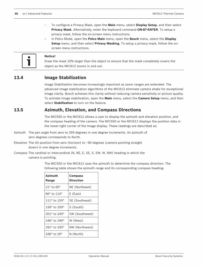
– To configure a Privacy Mask, open the Main menu, select Display Setup, and then selectPrivacy Mask. Alternatively, enter the keyboard command ON-87-ENTER. To setup aprivacy mask, follow the on-screen menu instructions.
– In Pelco Mode, open the Pelco Main menu, open the Bosch menu, select the DisplaySetup menu, and then select Privacy Masking. To setup a privacy mask, follow the on-screen menu instructions.
Notice!
Draw the mask 10% larger than the object to ensure that the mask completely covers the
object as the MIC612 zooms in and out.
Image StabilizationImage Stabilization becomes increasingly important as zoom ranges are extended. Theadvanced image stabilization algorithms of the MIC612 eliminate camera shake for exceptionalimage clarity. Bosch achieves this clarity without reducing camera sensitivity or picture quality.To activate image stabilization, open the Main menu, select the Camera Setup menu, and thenselect Stabilization to turn on the feature.
Azimuth, Elevation, and Compass DirectionsThe MIC550 or the MIC612 allows a user to display the azimuth and elevation position, andthe compass heading of the camera. The MIC550 or the MIC612 displays the position data inthe lower-right corner of the image display. These readings are described as:
Azimuth The pan angle from zero to 359 degrees in one degree increments. An azimuth ofzero degrees corresponds to North.
Elevation The tilt position from zero (horizon) to –90 degrees (camera pointing straightdown) in one degree increments.
Compass The cardinal or intercardinal (N, NE, E, SE, S, SW, W, NW) heading in which thecamera is pointing.
The MIC550 or the MIC612 uses the azimuth to determine the compass direction. Thefollowing table shows the azimuth range and its corresponding compass heading:
AzimuthRange
CompassDirection
21° to 65° NE (Northeast)
66° to 110° E (East)
111° to 155° SE (Southeast)
156° to 200° S (South)
201° to 245° SW (Southwest)
246° to 290° W (West)
291° to 335° NW (Northwest)
336° to 20° N (North)
13.4
13.5
80 en | Advanced Features MIC612 Thermal Camera
2016.03 | 2.2 | F.01U.249.416 Operation Manual Bosch Security Systems
Setting the Azimuth Zero PointThe MIC550 or the MIC612 uses the Azimuth Zero point, usually set to magnetic North, as thezero degree pan position and as the North compass heading. The MIC550 or the MIC612 thendisplays the azimuth reading and the compass heading based on the number of degrees fromthe Azimuth Zero point.
!
Caution!
Bosch recommends that only the installer calibrate the Azimuth Zero point. A recalibration to
the Azimuth Zero point may cause inaccurate compass headings.
To set the Azimuth Zero point:1. Determine the North compass heading, then move the camera to that position.2. Press OFF-90-ENTER to turn off the command lock (if active).3. Press ON-94-ENTER to set the Azimuth Zero point.
Displaying Azimuth, Elevation, and Compass HeadingsYou can display only the azimuth/elevation readings or only the compass reading, or you candisplay both readings at the same time. The MIC550 or the MIC612 displays the azimuth/elevation readings and the compass heading in the following way:180 / –45 Swhere:– 180 is the Azimuth or the pan location in degrees.– –45 is the Elevation or the tilt location in degrees.– S is the compass direction (cardinal or intercardinal). 1. Press ON-95-ENTER to display the azimuth/elevation reading.2. Press ON-96-ENTER to display the compass heading.3. Press OFF-95-ENTER to hide the azimuth/elevation reading.4. Press OFF-96-ENTER to hide the compass heading.
13.5.1
13.5.2
MIC612 Thermal Camera Advanced Features | en 81
Bosch Security Systems Operation Manual 2016.03 | 2.2 | F.01U.249.416

Maintenance and TroubleshootingCleaning - Unplug the device before cleaning. Generally, using a dry cloth for cleaning issufficient, but a moist, fluff-free cloth may also be used. Do not use liquid cleaners or aerosolcleaners.
No User-serviceable PartsExcept for the external wiper blade, the device contains no user-serviceable parts. Contactyour local Bosch service center for device maintenance and repair. In the event of failure, thedevice should be removed from site for repair.
On-Site InspectionIt is recommended that the device be inspected on-site every six months to check mountingbolts for tightness, security, and any signs of physical damage. Inspection of this device shallonly be carried out by suitably-trained personnel in accordance with the applicable code ofpractice (for example, EN 60097-17).
Table of Troubleshooting IssuesThe table below identifies issues that could occur with the camera, and how to resolve them.
Problem Questions to Ask/Actions to Resolve the Problem
No camera control. – Ensure that the LAN cable has good connection andis secured.– Refresh the browser and ensure that video isupdated.– Cycle the camera's power off and on.
Video is rolling, noisy, or distorted. – Check the integrity of all connectors and splices ofthe Ethernet cable.If O.K., then:– Contact Bosch Technical Support.
Camera moves when attempting tomove other cameras.
– Check that the camera’s IP address is properly set.If camera’s IP address is not set, then:– Use Configuration Manager to confirm that twocameras do not have the same IP address. If they do,change the address of one of the cameras.
No Network Connection. – Check all network connections.– Ensure that the maximum distance between anytwo Ethernet connections is 100 m (328 ft) or less.If O.K., then:– If you are behind a firewall, ensure that the VideoTransmission mode is set to UDP.
Camera does not operate at all, ordoes not operate as expected, afterbeing subjected to extreme lowtemperatures (below -40 ° (-40 °F)).
- Allow the camera to warm up. The camera requiresa 60-minute warm-up prior to PTZ operations.- If camera does not operate after this warm-upperiod, then reset the camera. In the URL line of yourweb browser, type “/reset” at the end of the IPaddress of the camera.
14
82 en | Maintenance and Troubleshooting MIC612 Thermal Camera
2016.03 | 2.2 | F.01U.249.416 Operation Manual Bosch Security Systems

Nothing appears on the screen. Are the power cord and line connection between thecamera and monitor made properly?
The image on the screen is dim. Is the lens dirty? If so, clean the lens with a soft,clean cloth.
The contrast on the screen is tooweak.
Adjust the contrast feature of the monitor. Is thecamera exposed to strong light? If so, change thecamera position.
The image on the screen flickers. Does the camera face directly into the sun orfluorescent lighting? If so, reposition camera.
The image on the screen is distorted. Is the power frequency set properly in sync? If thepower frequency is not set correctly, the line locksynchronization mode cannot be used. Set thesynchronization mode to INT. (NTSC Model powerfrequency in LL mode: 60 Hz.)
No video. – Check that the mains power to the power supply ison.– For IP-enabled cameras: Check to see if you have aweb page.If you do, then try cycling the camera’s power off andon.If you do not, then you may have the wrong IPaddress. Use Configuration Manager to identify thecorrect IP address.If O.K., then:– Check that there is 24 V output from thetransformer.If O.K., then:– Check the integrity of all wires and matingconnectors to the camera.
Picture is dark. – Check that the Gain Control is set to High.If O.K., then:– Check that the Auto Iris Level is set to theappropriate level.If O.K., then:– Check that the camera lens cover is removed.If O.K., then:– Check that the maximum Ethernet cable distancehas not been exceeded.If O.K., then:– Restore all camera settings.
Background is too bright to seesubject.
Turn on backlight compensation.
Additional troubleshooting for MIC612 cameras.
MIC612 Thermal Camera Maintenance and Troubleshooting | en 83
Bosch Security Systems Operation Manual 2016.03 | 2.2 | F.01U.249.416

Problem Explanation Solution
A green square appearsintermittently at the upperright of the video output.
This is the Flat Field ImminentSymbol. It warns that FFC is aboutto begin.
Do nothing; this isnormal operation forthe thermal camera.
The thermal imageappears ’grainy’.
This often occurs when thetemperature of the camerafluctuates, such as after the camerais powered on, or when ambienttemperature is changing.
Perform a flat-fieldcorrection (FFC).
84 en | Maintenance and Troubleshooting MIC612 Thermal Camera
2016.03 | 2.2 | F.01U.249.416 Operation Manual Bosch Security Systems

Technical dataFor product specifications, see the datasheet for your camera, available on the appropriateproduct pages of the Online Product Catalog at www.boschsecurity.com.
15
MIC612 Thermal Camera Technical data | en 85
Bosch Security Systems Operation Manual 2016.03 | 2.2 | F.01U.249.416

Appendices
Keyboard Commands (Bosch Protocol) By Number
Commands, Optical Camera
Locked Function Key
CommandNo.
Command Description
On/Off 1 Scan 360° / Auto Pan (Continuous) Activates/deactivates Autopan withoutlimits.
On/Off 2 Autopan (within Limits) Activates/deactivates Autopan betweenlimits.
* On/Off 3 Iris Control Enters the menu (auto, manual) for iriscontrol.
* On/Off 4 Focus Control Enters the menu (spot, auto, manual) forfocus control.
On/Off 7 Play Custom Pre-position Tour Activates/Deactivates the playback of acustom, pre-position tour.
On/Off 8 Play Pre-position Tour Activates/Deactivates the playback of apre-position tour.
* On/Off 9 Inactivity Mode Enters the inactivity menu (Off, Return toScene 1, Recall Previous PTZ Command).
* On/Off 11 Auto Iris Level Adjust Enters the Iris Level Adjustment menu.
On/Off 14 Set Autopan and Scan Speed Enters the speed adjustment slide bar.
On/Off 15 Set Pre-position Tour Period(dwell)
Enters the dwell adjustment slide bar.
* On/Off 18 AutoPivot Enable Enables/disables AutoPivot.
On/Off 20 Backlight Comp Turns Backlight Compensation on or off.
* On/Off 23 Electronic Shutter Enters the Shutter Speed slide bar.
On/Off 24 Stabilization Turns Electronic Stabilization on or off.
On/Off 26 Wide Dynamic Range Activates/deactivates Wide Dynamic Range.
On/Off 30 White Balance Enters the White Balance menu.
* On/Off 35 Fixed White Balance Enters the White Balance menu.
* On 40 Restore Camera Settings Restores all settings to their originaldefaults.
* On/Off 43 Auto Gain Control Switches AGC modes (On, Auto, Off).
* On/Off 44 Aperturn Correction (Sharpness) Enters the Sharpness menu.
* On 46 Advanced Menu Enters the Main Setup menu.
On 47 View Factory Settings Displays all menu default settings.
16
16.1
16.1.1
86 en | Appendices MIC612 Thermal Camera
2016.03 | 2.2 | F.01U.249.416 Operation Manual Bosch Security Systems

Locked Function Key
CommandNo.
Command Description
On/Off 50 Playback A, continuous Activates/Deactivates continuous playbackA.
On/Off 51 Playback A, single Activates/Deactivates single playback A.
On/Off 52 Playback B, continuous Activates/Deactivates continuous playbackB.
On/Off 53 Playback B, single Activates/Deactivates single playback B.
On/Off/ 56 Night Mode Menu Enters the Night Mode memnu (On, Off;Auto (Day/Night only))
On/Off 57 Night Mode Control (IR Filter In/Out)
Enables/disables Night Mode (Day = Off /Night = On).
* On/Off 58 Day/Night Threshold Enables/disables the day/nigh threshold(On–menu (Day/Night only)).
On/Off 59 Night Mode Priority Motion–Activates Night Mode before slowshutter, preserving full-frame integration aslight is reduced.Color–Activates slow shutter before NightMode, preserving color longer as light isreduced.
* On/Off 60 On Screen Display On–Enables on-screen display.Off–Disables on-screen display.
* On 61 OSD Display (Adjust) Adjusts the view of the On-screen Display.
On 62 Pre-position (Scene) Title menu Enters the Pre-position Title menu. Refer toSpecifying a Shot or a Sector Title.
* On 63 Zone/Sector Title Menu Enters the Zone Title menu. Refer toSpecifying a Shot or a Sector Title.
On 64 Alarm Status Enters the Alarm Status menu.
Off 65 Alarm Acknowledge Acknowledges alarms or deactivatesphysical outputs.
On 66 Display Software Version Displays the number of the softwareversion.
On/Off 67 Focus Adjust for IR Illuminators On - Automatically adjusts camera focuswith IR illumination is present.
* On/Off 69 Alarm Rule Activation/Deactivation On–Enables all alarm rules.Off–Disables all alarm rules.
On 72 Re-initialize Camera Performs camera/lens re-initializationfunctions.
* On/Off 80 Digital Zoom Lock Turns digital zoom on and off.
MIC612 Thermal Camera Appendices | en 87
Bosch Security Systems Operation Manual 2016.03 | 2.2 | F.01U.249.416

Locked Function Key
CommandNo.
Command Description
On/Off 81 Alarm Output 1Open Collector
On–Activates output.Off–Deactivates output.
On/Off 82 Alarm Output 2Open Collector
On–Activates output.Off–Deactivates output.
On/Off 83 Alarm Output 3Open Collector
On–Activates output.Off–Deactivates output.
On/Off 84 Alarm Relay On–Activates alarm relay.Off–Deactivates alarm relay.
* On/Off 86 Sector Blanking / Masking Enters / Exits the Sector Blanking menu.
* On/Off 87 Privacy Masking Enters / Exits the Privacy Masking menu.
On/Off 89 Preposition Overwrite Confirmation(toggle)
On–Isues a message that prompts forapproval to overwrite a preposition.Off–No confirmation message issued.
On/Off 90 Command Lock/Unlock On–Lock onOff–Lock off
* On/Off 91 Zoom Polarity On–ReverseOff–Normal
* On/Off 92 Focus Polarity On–ReverseOff–Normal
* On/Off 93 Iris Polarity On–ReverseOff–Normal
* On/Off 94 Set Azimuth Zero Point /Recalibrate Azimuth Compass
Sets the zero degree pan position.Refer to Azimuth, Elevation, and CompassDirections, page 80.
On/Off 95 Display Azimuth/Elevation Readings On–Displays azimuth/elevation readings.Off–Hides azimuth/elevation readings.Refer to Azimuth, Elevation, and CompassDirections, page 80.
On/Off 96 Display Compass (Point) Readings On–Displays compass heading.Off–Hides compass heading.Refer to Azimuth, Elevation, and CompassDirections, page 80.
On/Off 97 Video channel (toggle) On - Switches view to thermal camera.Off - Switches view to optical camera.
On 99 Factory P/T Home Position Recalibrates home position; can be used asan Alarm Output.
On/Off 100 Record A Activates/deactivates recording A.
On/Off 101 Record B Activates/deactivates recording B.
88 en | Appendices MIC612 Thermal Camera
2016.03 | 2.2 | F.01U.249.416 Operation Manual Bosch Security Systems

Locked Function Key
CommandNo.
Command Description
On/Off 102 Wiper continuous Turns on/off continous wiper mode.
On/Off 103 Wiper intermittent Activates the wiper in Intermittent mode(the wiper wipes twice, then turns off after15 seconds).
On/Off 104 Wiper one shot Activates (One shot) to wipe five times,then turn off.
On/Off 105 Wash/Wipe Activates wash/wip mode. Cameras movesto designated washer preset (62), wiperstarts automatically.
On 997 FastAddress, display Display the current FastAddress of thecamera.
On 998 FastAddress, all units Displays the current FastAddress of thecamera and programs all units.
On 999 FastAddress, unaddressed cameras Displays and programs unaddressed MICunits.
Set “1-99” Pre-position Programming Set ##–Programs a preset view.
Shot “1-99” Pre-position Recall Shot ##–Recall programmed preset.
Set 100 Pre-position Menu Enters the Pre-position menu.
Set/Shot
101 Autopan Left Limit Set–Programs left limit.Shot–Shows limit.
Set/Shot
102 Autopan Right Limit Set–Programs right limit.Shot–Shows limit.
Set 110 Factory P/T Home Position Set–Recalibrate home position.
* Set 802 Edit Password Enters the Edit Password menu.
* Set 899 Reset ALL Restores all settings to original defaultsand clears all user-programmed settings.
Set 900 Edit Tour 1 (Standard) Enters the Standard Tour Scene menu.
Shot 900 Edit Tour 2 (Custom) Enters the Custom Tour Scene menu.
Set/Shot
901-999 Adds/Removes a Preposition Shotfrom Tour 1
Set ###–Adds preset.Shot ###–Removes preset.
Commands, Thermal Camera
Locked Function Key
CommandNo.
Command Description
On/Off 1 Scan 360° Autopan without limits.
On/Off 2 Autopan Autopan between limits.
16.1.2
MIC612 Thermal Camera Appendices | en 89
Bosch Security Systems Operation Manual 2016.03 | 2.2 | F.01U.249.416

Locked Function Key
CommandNo.
Command Description
On/Off 7 Play Custom Pre-position Tour Activates/Deactivates the playback of acustom, pre-position tour.
On/Off 8 Play Pre-position Tour Activates/Deactivates the playback of apre-position tour.
* On/Off 18 AutoPivot Enable Enables/disables AutoPivot.
On/Off 50 Playback A, continuous Activates/Deactivates continuous playbackA.
On/Off 51 Playback A, single Activates/Deactivates single playback A.
On/Off 52 Playback B, continuous Activates/Deactivates continuous playbackB.
On/Off 53 Playback B, single Activates/Deactivates single playback B.
* On/Off 69 Alarm Rule Activation/Deactivation On–Enables all alarm rules.Off–Disables all alarm rules.
* On/Off 80 Digital Zoom Lock Turns digital zoom on and off.
On/Off 81 Alarm Output 1Open Collector
On–Activates output.Off–Deactivates output.
On/Off 82 Alarm Output 2Open Collector
On–Activates output.Off–Deactivates output.
On/Off 83 Alarm Output 3Open Collector
On–Activates output.Off–Deactivates output.
On/Off 84 Alarm Output 4Relay
On–Activates output.Off–Deactivates output
On/Off 88 Proportional PTZ On–Activates Proportional PTZ.Off–Deactivates Proportional PTZ.
On/Off 90 Command Lock/Unlock On–Turns on the lock.Off–Turns off the lock.
On/Off 97 Video channel (toggle) On - Switches view to thermal camera.Off - Switches view to optical camera.
On 99 Factory P/T Home Position Recalibrates home position; can be used asan Alarm Output.
On/Off 100 Record A Activates/Deactivates recording A.
On/Off 101 Record B Activates/Deactivates recording B.
102 Wiper alarm Turns the wiper alarm on/off manually.
103 Wiper wipe Activates the wiper in Intermittent mode(the wiper wipes twice, then turns off after15 seconds).
90 en | Appendices MIC612 Thermal Camera
2016.03 | 2.2 | F.01U.249.416 Operation Manual Bosch Security Systems

Locked Function Key
CommandNo.
Command Description
104 Wiper wipe Activates (On shot) to wipe five times, thenturn off.
105 Washer/Wiper Activates the washer/wiper.
On 454 White Hot Activates thermal display mode White Hot.
Off 454 Black Hot Activates thermal display mode Black Hot.
On 455 Ice Fire Activates thermal display mode Ice Fire.
Off 455 Globow Activates thermal display mode Globow.
On 456 Ironbow 1 Activates thermal display mode Ironbow 1.
Off 456 Ironbow 2 Activates thermal display mode Ironbow 2.
On 457 Rainbow Activates thermal display mode Rainbow.
Off 457 Fusion Activates thermal display mode Fusion.
On 458 Sepia Activates thermal display mode Sepia.
Off 458 Rain Activates thermal display mode Rain.
On 459 Color 1 Activates thermal display mode Color 1.
Off 459 Color 2 Activates thermal display mode Color 2.
On 460 Red Hot Activates thermal display mode Red Hot.
Off 460 Green Hot Activates thermal display mode Green Hot.
On 463 SPOT meter display Activates the SPOT meter.
Off 463 SPOT meter display Deactivates the SPOT meter.
On 997 FastAddress, display Display the current FastAddress of thecamera.
On 998 FastAddress, all units Displays the current FastAddress of thecamera and programs all units.
On 999 FastAddress, unaddressed cameras Displays and programs unaddressed MICunits.
Set “1-99” Pre-position Programming Set ##–Programs a preset view.
Shot “1-99” Pre-position Recall Shot ##–Recall programmed preset.
Set/Shot
100 Pre-position Store/Clear Enters/ Exits pre-position menu.
Set/Shot
101 Autopan Left Limit Set–Programs left limit.Shot–Shows limit.
Set/Shot
102 Autopan Right Limit Set–Programs right limit.Shot–Shows limit.
Set/Shot
103 Lock Commands Locks commands.
MIC612 Thermal Camera Appendices | en 91
Bosch Security Systems Operation Manual 2016.03 | 2.2 | F.01U.249.416

Locked Function Key
CommandNo.
Command Description
Set/Shot
104 Unlock Commands Unlocks commands.
Set/Shot
106 Pre-wash position Sets the camera in pre-wash position.
Set 110 Factory P/T Home Position Recalibrates home position.
92 en | Appendices MIC612 Thermal Camera
2016.03 | 2.2 | F.01U.249.416 Operation Manual Bosch Security Systems


Bosch Security Systems, Inc.1706 Hempstead RoadLancaster, PA, 17601USAwww.boschsecurity.com© Bosch Security Systems, Inc., 2016
Bosch Sicherheitssysteme GmbHRobert-Bosch-Ring 585630 GrasbrunnGermanywww.boschsecurity.com