Dinion IP Camera -...
132
Dinion IP Camera NBC-455 en Installation and Operation Manual
Transcript of Dinion IP Camera -...
Dinion IP CameraNBC-455
en Installation and Operation Manual


Dinion IP Camera Table of Contents | en 3
Bosch Security Systems Installation and Operation Manual AR18-10-B006 | v1.1 | 2010.06
Table of Contents
1 Safety 81.1 Safety precautions 81.2 Important safety instructions 91.3 Connection in applications 101.4 FCC & ICES compliance 111.5 UL certification 131.6 Bosch notices 141.7 Copyrights 15
2 Introduction 162.1 Features 16
3 System Information 183.1 Overview of functions 183.1.1 Progressive scan 183.1.2 Tri-streaming 183.1.3 ONVIF (Open Network Video Interface Forum) 183.1.4 Audio 183.1.5 Alarm I/O 183.1.6 Tamper detection and motion detectors 193.1.7 Video encoding 193.1.8 Multicast 193.1.9 Power-over-Ethernet 193.1.10 Data interface 193.1.11 Encryption 193.1.12 Receiver 203.1.13 Recording 203.1.14 Snapshots 203.1.15 Backup 203.1.16 Configuration 203.2 Operation with external systems 21
4 en | Table of Contents Dinion IP Camera
AR18-10-B006 | v1.1 | 2010.06 Installation and Operation Manual Bosch Security Systems
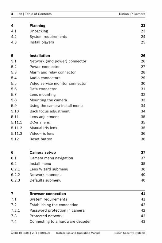
4 Planning 234.1 Unpacking 234.2 System requirements 244.3 Install players 25
5 Installation 265.1 Network (and power) connector 265.2 Power connector 275.3 Alarm and relay connector 285.4 Audio connectors 295.5 Video service monitor connector 305.6 Data connector 315.7 Lens mounting 325.8 Mounting the camera 335.9 Using the camera install menu 345.10 Back focus adjustment 345.11 Lens adjustment 355.11.1 DC-iris lens 355.11.2 Manual-iris lens 355.11.3 Video-iris lens 365.12 Reset button 36
6 Camera set-up 376.1 Camera menu navigation 376.2 Install menu 386.2.1 Lens Wizard submenu 386.2.2 Network submenu 406.2.3 Defaults submenu 40
7 Browser connection 417.1 System requirements 417.2 Establishing the connection 427.2.1 Password protection in camera 427.3 Protected network 427.4 Connecting to a hardware decoder 43
Dinion IP Camera Table of Contents | en 5
Bosch Security Systems Installation and Operation Manual AR18-10-B006 | v1.1 | 2010.06
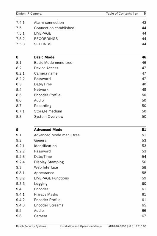
7.4.1 Alarm connection 437.5 Connection established 447.5.1 LIVEPAGE 447.5.2 RECORDINGS 447.5.3 SETTINGS 44
8 Basic Mode 468.1 Basic Mode menu tree 468.2 Device Access 478.2.1 Camera name 478.2.2 Password 478.3 Date/Time 488.4 Network 498.5 Encoder Profile 508.6 Audio 508.7 Recording 508.7.1 Storage medium 508.8 System Overview 50
9 Advanced Mode 519.1 Advanced Mode menu tree 519.2 General 539.2.1 Identification 539.2.2 Password 539.2.3 Date/Time 549.2.4 Display Stamping 569.3 Web Interface 589.3.1 Appearance 589.3.2 LIVEPAGE Functions 599.3.3 Logging 609.4 Encoder 619.4.1 Privacy Masks 619.4.2 Encoder Profile 619.4.3 Encoder Streams 659.5 Audio 669.6 Camera 67
6 en | Table of Contents Dinion IP Camera
AR18-10-B006 | v1.1 | 2010.06 Installation and Operation Manual Bosch Security Systems
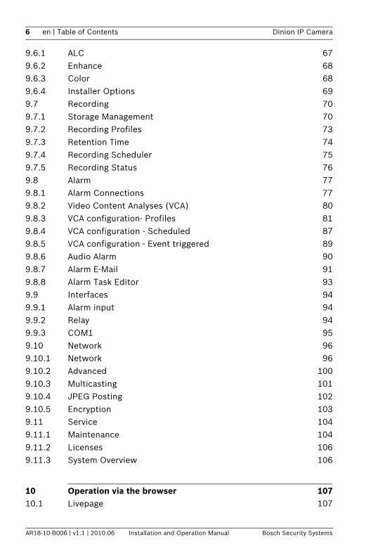
9.6.1 ALC 679.6.2 Enhance 689.6.3 Color 689.6.4 Installer Options 699.7 Recording 709.7.1 Storage Management 709.7.2 Recording Profiles 739.7.3 Retention Time 749.7.4 Recording Scheduler 759.7.5 Recording Status 769.8 Alarm 779.8.1 Alarm Connections 779.8.2 Video Content Analyses (VCA) 809.8.3 VCA configuration- Profiles 819.8.4 VCA configuration - Scheduled 879.8.5 VCA configuration - Event triggered 899.8.6 Audio Alarm 909.8.7 Alarm E-Mail 919.8.8 Alarm Task Editor 939.9 Interfaces 949.9.1 Alarm input 949.9.2 Relay 949.9.3 COM1 959.10 Network 969.10.1 Network 969.10.2 Advanced 1009.10.3 Multicasting 1019.10.4 JPEG Posting 1029.10.5 Encryption 1039.11 Service 1049.11.1 Maintenance 1049.11.2 Licenses 1069.11.3 System Overview 106
10 Operation via the browser 10710.1 Livepage 107
Dinion IP Camera Table of Contents | en 7
Bosch Security Systems Installation and Operation Manual AR18-10-B006 | v1.1 | 2010.06
10.1.1 Processor load 10710.1.2 Image selection 10810.1.3 View Control 10810.1.4 Digital I/O 10810.1.5 System Log / Event Log 10810.1.6 Saving snapshots 10810.1.7 Recording video sequences 10910.1.8 Running recording program 10910.1.9 Audio communication 10910.2 Recordings page 11010.2.1 Controlling playback 110
11 Troubleshooting 11211.1 Function test 11211.2 Resolving problems 11311.3 Customer service 115
12 Maintenance 11612.1 Testing the network connection 11612.2 Communication with Terminal Program 11612.3 Repairs 11812.3.1 Transfer and disposal 118
13 Technical Data 11913.1 Specifications 11913.1.1 Dimensions 12213.1.2 Accessories 123
Glossary 124
8 en | Safety Dinion IP Camera
AR18-10-B006 | v1.1 | 2010.06 Installation and Operation Manual Bosch Security Systems
1 Safety
1.1 Safety precautions
DANGER! High risk: This symbol indicates an imminently hazardous situation such as "Dangerous Voltage" inside the product.If not avoided, this will result in an electrical shock, serious bodily injury, or death.
WARNING! Medium risk: Indicates a potentially hazardous situation.If not avoided, this could result in minor or moderate bodily injury.
CAUTION! Low risk: Indicates a potentially hazardous situation.If not avoided, this could result in property damage or risk of damage to the unit.
Dinion IP Camera Safety | en 9
Bosch Security Systems Installation and Operation Manual AR18-10-B006 | v1.1 | 2010.06
1.2 Important safety instructionsRead, follow, and retain for future reference all of the following safety instructions. Follow all warnings on the unit and in the operating instructions before operating the unit.1. Clean only with a dry cloth. Do not use liquid cleaners or
aerosol cleaners.2. Do not install unit near any heat sources such as radiators,
heaters, stoves, or other equipment (including amplifiers) that produce heat.
3. Never spill liquid of any kind on the unit.4. Take precautions to protect the unit from power and
lightning surges.5. Adust only those controls specified in the operating
instructions.6. Operate the unit only from the type of power source
indicated on the label.7. Unless qualified, do not attempt to service a damaged unit
yourself. Refer all servicing to qualified service personnel.8. Install in accordance with the manufacturer's instructions
in accordance with applicable local codes. Use only attachments/accessories specified by the manufacturer. Equipment change or modification could void the user's guarantee or authorization agreement.
10 en | Safety Dinion IP Camera
AR18-10-B006 | v1.1 | 2010.06 Installation and Operation Manual Bosch Security Systems
1.3 Connection in applicationsPower lines: An outdoor system should not be located in the vicinity of overhead power lines, electrical lights, or power circuits, or where it may contact such power lines or circuits. When installing an outdoor system, extreme care should be taken to keep from touching power lines or circuits, as this contact may be fatal.U.S.A. models only - refer to the National Electrical Code Article 820 regarding installation of CATV systems.12 VDC / 24 VAC power source: This unit is intended to operate with a limited power source. The unit is intended to operate at either 12 VDC or 24 VAC (if PoE is not available). User supplied wiring must be in compliance with electrical codes (Class 2 power levels). If 24 VAC is used, do not ground the 24 VAC supply at the terminals or at the unit's power supply terminals.PoE: Use only approved PoE devices. Power-over-Ethernet can be connected at the same time as a 12 VDC or 24 VAC power supply.
CAUTION! The Low Voltage power supply unit must comply with EN/UL 60950. The power supply must be a SELV-LPS unit or a SELV - Class 2 unit (Safety Extra Low Voltage - Limited Power Source).
Dinion IP Camera Safety | en 11
Bosch Security Systems Installation and Operation Manual AR18-10-B006 | v1.1 | 2010.06
1.4 FCC & ICES complianceFCC & ICES Information(U.S.A. and Canadian Models Only)This equipment has been tested and found to comply with the limits for a Class B digital device, pursuant to part 15 of the FCC Rules. These limits are designed to provide reasonable protection against harmful interference in a residential installation. This equipment generates, uses, and can radiate radio frequency energy and, if not installed and used in accordance with the instructions, may cause harmful interference to radio communications. However, there is no guarantee that interference will not occur in a particular installation. If this equipment does cause harmful interference to radio or television reception, which can be determined by turning the equipment off and on, the user is encouraged to try to correct the interference by one or more of the following measures:– reorient or relocate the receiving antenna;– increase the separation between the equipment and
receiver;– connect the equipment into an outlet on a circuit different
from that to which the receiver is connected;– consult the dealer or an experienced radio/TV technician
for help.Intentional or unintentional modifications, not expressly approved by the party responsible for compliance, shall not be made. Any such modifications could void the user's authority to operate the equipment. If necessary, the user should consult the dealer or an experienced radio/television technician for corrective action.The user may find the following booklet, prepared by the Federal Communications Commission, helpful: How to Identify and Resolve Radio-TV Interference Problems. This booklet is available from the U.S. Government Printing Office, Washington, DC 20402, Stock No. 004-000-00345-4.
12 en | Safety Dinion IP Camera
AR18-10-B006 | v1.1 | 2010.06 Installation and Operation Manual Bosch Security Systems
Informations FCC et ICES(modèles utilisés aux États-Unis et au Canada uniquement)Suite à différents tests, cet appareil s'est révélé conforme aux exigences imposées aux appareils numériques de classe B, en vertu de la section 15 du règlement de la Commission fédérale des communications des États-Unis (FCC), et en vertu de la norme ICES-003 d'Industrie Canada. Ces exigences visent à fournir une protection raisonnable contre les interférences nuisibles lorsque l'appareil est utilisé dans le cadre d'une installation résidentielle. Cet appareil génère, utilise et émet de l'énergie de radiofréquences et peut, en cas d'installation ou d'utilisation non conforme aux instructions, engendrer des interférences nuisibles au niveau des radiocommunications. Toutefois, rien ne garantit l'absence d'interférences dans une installation particulière. Il est possible de déterminer la production d'interférences en mettant l'appareil successivement hors et sous tension, tout en contrôlant la réception radio ou télévision. L'utilisateur peut parvenir à éliminer les interférences éventuelles en prenant une ou plusieurs des mesures suivantes:– Modifier l'orientation ou l'emplacement de l'antenne
réceptrice;– Éloigner l'appareil du récepteur;– Brancher l'appareil sur une prise située sur un circuit
différent de celui du récepteur;– Consulter le revendeur ou un technicien qualifié en radio/
télévision pour obtenir de l'aide.Toute modification apportée au produit, non expressément approuvée par la partie responsable de l'appareil, est strictement interdite. Une telle modification est susceptible d'entraîner la révocation du droit d'utilisation de l'appareil. La brochure suivante, publiée par la Commission fédérale des communications (FCC), peut s'avérer utile : Comment identifier et résoudre les problèmes d’interférences de radio et de télévision. Cette brochure est disponible auprès du U.S. Government Printing Office, Washington, DC 20402, États-Unis, sous la référence n° 004-000-00345-4.
Dinion IP Camera Safety | en 13
Bosch Security Systems Installation and Operation Manual AR18-10-B006 | v1.1 | 2010.06
1.5 UL certificationDisclaimerUnderwriter Laboratories Inc. ("UL") has not tested the performance or reliability of the security or signaling aspects of this product. UL has only tested fire, shock and/or casualty hazards as outlined in UL's Standard(s) for Safety for Information Technology Equipment, UL 60950-1. UL Certification does not cover the performance or reliability of the security or signaling aspects of this product.UL MAKES NO REPRESENTATIONS, WARRANTIES, OR CERTIFICATIONS WHATSOEVER REGARDING THE PERFORMANCE OR RELIABILITY OF ANY SECURITY OR SIGNALING RELATED FUNCTIONS OF THIS PRODUCT.
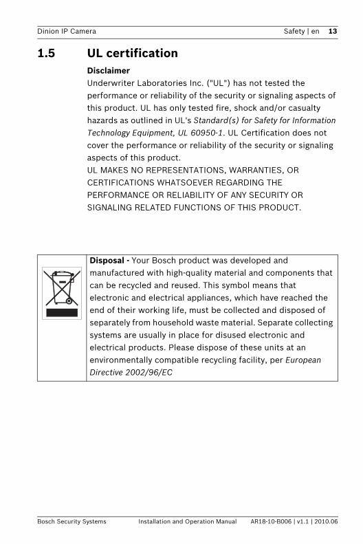
Disposal - Your Bosch product was developed and manufactured with high-quality material and components that can be recycled and reused. This symbol means that electronic and electrical appliances, which have reached the end of their working life, must be collected and disposed of separately from household waste material. Separate collecting systems are usually in place for disused electronic and electrical products. Please dispose of these units at an environmentally compatible recycling facility, per European Directive 2002/96/EC
14 en | Safety Dinion IP Camera
AR18-10-B006 | v1.1 | 2010.06 Installation and Operation Manual Bosch Security Systems
1.6 Bosch noticesVideo lossVideo loss is inherent to digital video recording; therefore, Bosch Security Systems cannot be held liable for any damage that results from missing video information. To minimize the risk of lost digital information, Bosch Security Systems recommends multiple, redundant recording systems, and a procedure to back up all analog and digital information.
CopyrightThis manual is the intellectual property of Bosch Security Systems and is protected by copyright.All rights reserved.
TrademarksAll hardware and software product names used in this document are likely to be registered trademarks and must be treated accordingly.
NoteThis manual has been compiled with great care and the information it contains has been thoroughly verified. The text was complete and correct at the time of printing. The ongoing development of the products may mean that the content of the user guide can change without notice. Bosch Security Systems accepts no liability for damage resulting directly or indirectly from faults, incompleteness or discrepancies between the user guide and the product described.
More informationFor more information please contact the nearest Bosch Security Systems location or visit www.boschsecurity.com
Dinion IP Camera Safety | en 15
Bosch Security Systems Installation and Operation Manual AR18-10-B006 | v1.1 | 2010.06
1.7 CopyrightsThe firmware 4.1 uses the fonts "Adobe-Helvetica-Bold-R-Normal--24-240-75-75-P-138-ISO10646-1" and "Adobe-Helvetica-Bold-R-Normal--12-120-75-75-P-70-ISO10646-1" under the following copyright:Copyright 1984-1989, 1994 Adobe Systems Incorporated.Copyright 1988, 1994 Digital Equipment Corporation.Permission to use, copy, modify, distribute and sell this software and its documentation for any purpose and without fee is hereby granted, provided that the above copyright notices appear in all copies and that both those copyright notices and this permission notice appear in supporting documentation, and that the names of Adobe Systems and Digital Equipment Corporation not be used in advertising or publicity pertaining to distribution of the software without specific, written prior permission.
This software is based in part on the work of the Independent JPEG Group.

16 en | Introduction Dinion IP Camera
AR18-10-B006 | v1.1 | 2010.06 Installation and Operation Manual Bosch Security Systems
2 Introduction
2.1 FeaturesThe Dinion IP camera is a professional color camera. The camera incorporates 10-bit digital signal processing for professional picture performance in natural or artificial lighting conditons. The camera uses H.264 compression technology to give clear images while reducing bandwidth and storage requirements. It is also ONVIF compliant to improve compatibility during system integration.The camera operates as a network video server and transmits video and control signals over data networks, such as Ethernet LANs and the Internet. The camera is easy to install and ready to use. Features include:– Progressive scan– Color performance with NightSense– 1/3-inch CCD sensor– Tri-streaming (two H.264 streams and one M-JPEG stream)– Complies with the ONVIF standard for wide compatibility– Two-way audio and audio alarm– Alarm input and alarm output to external devices– Enhanced video motion detection– Video and data transmission over IP data networks– Multicast function for simultaneous picture transmission to
multiple receivers– Integrated Ethernet interface (10/100 Base-T)– Power-over-Ethernet (PoE)– Remote control of all built-in functions via TCP/IP– Data interface RS485/RS422/RS232 for control of pan or
tilt heads or motorized zoom lenses (PTZ control)– Password protection to prevent unauthorized connection
or configuration changes– Event-driven, automatic connection (for example, at
switch-on and for alarms)
Dinion IP Camera Introduction | en 17
Bosch Security Systems Installation and Operation Manual AR18-10-B006 | v1.1 | 2010.06
– Fast, convenient configuration using the integrated Web server and a browser
– Firmware update through flash memory– Convenient upload and download of configuration data
18 en | System Information Dinion IP Camera
AR18-10-B006 | v1.1 | 2010.06 Installation and Operation Manual Bosch Security Systems
3 System Information
3.1 Overview of functionsThe camera incorporates a network video server. Its primary function is to encode video and control data for transmission over an IP network. With its H.264 encoding, it is ideally suited for IP communication and for remote access to digital video recorders and IP systems. The use of existing networks means that integration with CCTV systems or local networks can be achieved quickly and easily. Video images from a single camera can be simultaneously received on several receivers.
3.1.1 Progressive scanThe camera captures and processes progressively scanned images. When there is fast motion in a scene, progressively scanned images are generally sharper than interlaced images.
3.1.2 Tri-streamingTri-streaming allows the data stream to be encoded simultaneously according to three different, individually customized profiles. This creates two full H.264 streams that can serve different purposes and an additional M-JPEG stream.
3.1.3 ONVIF (Open Network Video Interface Forum)The camera complies to the ONVIF standard which means that it is easier to install and integrate into larger systems. The ONVIF standard is a global standard for the interface of network video products.
3.1.4 AudioTwo-way duplex audio is available in the unit for live voice communications or audio recording.
3.1.5 Alarm I/OThe alarm input can be used to control the functionality of the unit. An alarm output can control external devices.

Dinion IP Camera System Information | en 19
Bosch Security Systems Installation and Operation Manual AR18-10-B006 | v1.1 | 2010.06
3.1.6 Tamper detection and motion detectorsThe camera offers a wide range of configuration options for alarm signaling in the event of tampering with the camera. An algorithm for detecting movement in the video image is also part of the scope of delivery and can optionally be extended to include special video analysis algorithms.
3.1.7 Video encodingThe camera uses the H.264 compression standards. Thanks to efficient encoding, the data rate remains low even with high image quality and can also be adapted to local conditions within wide limits.
3.1.8 MulticastIn suitably configured networks, the multicast function enables simultaneous, real time transmission to multiple receivers. The prerequisite for this is that the UDP and IGMP V2 protocols are implemented on the network.
3.1.9 Power-over-EthernetPower for the camera can be supplied via a Power-over-Ethernet compliant network cable connection. With this configuration, only a single cable connection is required to view, power, and control the camera.
3.1.10 Data interfaceAn external communications port with RS485/RS422/RS232 is available to provide data to external devices, such as pan and tilt heads, for full PTZ control via the Ethernet interface.
3.1.11 Encryption The unit offers a variety of options for protection against unauthorized reading. Web browser connections can be protected using HTTPS. Protect the control channels via the SSL encryption protocol. With an additional license, the user data itself can be encrypted.
20 en | System Information Dinion IP Camera
AR18-10-B006 | v1.1 | 2010.06 Installation and Operation Manual Bosch Security Systems
3.1.12 ReceiverH.264 compatible hardware decoders can be used as a receiver. Computers with decoding software such as VIDOS, or computers with the Microsoft Internet Explorer web browser installed, can also be used as receivers.
3.1.13 RecordingThe camera can be used with an iSCSI server connected via the network to store long-term recordings.
3.1.14 SnapshotsIndividual video frames (snapshots) can be called up as JPEG images, stored on the hard drive, or displayed in a separate browser window.
3.1.15 BackupThe browser application has an icon for saving the video images provided by the unit as a file on your computer's hard drive. Clicking this icon stores the video sequences and they can be replayed with the Player from Bosch Security Systems included with the package.
3.1.16 ConfigurationThe camera can be configured using a browser on the local network (Intranet) or from the Internet. Similarly, firmware updates and rapid loading of device configurations are also possible. Configuration settings can be stored as files on a computer and copied from one camera to another.

Dinion IP Camera System Information | en 21
Bosch Security Systems Installation and Operation Manual AR18-10-B006 | v1.1 | 2010.06
3.2 Operation with external systemsThe camera can be used with a variety of Bosch software and hardware systems: – Bosch Video Management System– VIDOS video management software– DiBos 900 Series digital video recorder– Divar 700 Series digital video recorder
Note:When connected to any of these systems, many of the camera configuration parameters are controlled by the system and not by the settings made via a web browser connected to the camera.
Bosch Video Management SystemThe Bosch Video Management System is a unique enterprise IP video surveillance solution that provides seamless management of digital video, audio, and data across any IP network. It is designed to work with Bosch CCTV products as part of a total video surveillance management system. Integrate your existing components into one easy-to-manage system, or use Bosch’s full-line capabilities and benefit from a complete surveillance solution based on cutting-edge technology and years of experience.
VIDOSThe camera video server and VIDOS software combine to provide a high-performance system solution. VIDOS is software for operating, controlling, and administering CCTV installations (such as surveillance systems) at remote locations. It runs under Microsoft Windows operating systems. Its main job is decoding video, audio, and control data from a remote transmitter. There are many options available for operation and configuration when using a camera with VIDOS.
DiBos 900 SeriesThe camera is also designed for use with DiBos 900 Series Video Recorders. DiBos can record up to 32 video and audio
22 en | System Information Dinion IP Camera
AR18-10-B006 | v1.1 | 2010.06 Installation and Operation Manual Bosch Security Systems
streams, and is available as software or as a hybrid DVR with additional analog camera and audio inputs. DiBos supports various functions of the camera, such as controlling relays, remote control of peripheral devices, and remote configuration. DiBos can use alarm inputs to trigger actions and, when motion detection Motion+ is active, can record the relevant cells, making intelligent motion detection possible.
Divar 700 SeriesThe Divar 700 Series of digital video recorders can view and record images from the camera via a network connection. The Divar 700 Series controls the camera so that the correct settings are used.
Dinion IP Camera Planning | en 23
Bosch Security Systems Installation and Operation Manual AR18-10-B006 | v1.1 | 2010.06
4 Planning
4.1 UnpackingUnpack carefully and handle the equipment with care. The packaging contains:– Dinion IP camera– CCD protection cap (mounted on camera)– Power connector– Alarm I/O connector– Data connector– DVD ROM (mini)
– Manual– System requirements– Configuration Manager– BVIP Lite Suite– MPEG ActiveX control– DirectX control– Microsoft Internet Explorer– Sun JVM– Player and Archive Player– Adobe Acrobat Reader
– Quick install instructions– Safety instructionsIf equipment has been damaged during shipment, repack it in the original packaging and notify the shipping agent or supplier.
24 en | Planning Dinion IP Camera
AR18-10-B006 | v1.1 | 2010.06 Installation and Operation Manual Bosch Security Systems
4.2 System requirements– Computer with Windows XP/Vista operating system,
network access, and Microsoft Internet Explorer web browser version 7.0 or lateror
– Computer with Windows XP/Vista operating system, network access and reception software, for example VIDOS, Bosch VMS, or DIBOS 900 Seriesor
– H.264 compatible hardware decoder from Bosch Security Systems (such as VIP XD) as a receiver and a connected video monitoror
– Divar 700 Series Digital Video Recorder
The minimum PC requirements are:– Operating platform: A PC running Windows XP or
Windows Vista with IE 7.0– Processor: Dual core, 3.0 GHz– RAM memory: 256 MB– Monitor resolution: 1024 x 768 – Network interface: 100-BaseT– DirectX: 9.0cMake sure the graphics card is set to 16-bit or 32-bit color depth and that Sun JVM is installed on your PC. To play back live video images, an appropriate ActiveX must be installed on the computer. If necessary, install the required software and controls from the product DVD provided. For further assistance, contact your PC system administrator.
Dinion IP Camera Planning | en 25
Bosch Security Systems Installation and Operation Manual AR18-10-B006 | v1.1 | 2010.06
4.3 Install playersPlay back saved-video sequences using the Player from Bosch Security Systems. This can be found on the DVD-ROM supplied.to play back saved sequences using the Player, suitable ActiveX software must be installed on the computer.1. Insert the DVD into the DVD-ROM drive of the computer. If
the DVD does not start automatically, open the DVD in Windows Explorer and double-click the index.html file to start the installation.
2. Select a language from the list box at the top.3. Click Tools in the menu.4. Click Archive Player; the installation starts.5. Follow the instructions in the installation program. The
Archive Player is installed together with the Player. 6. After a successful installation, two new icons for the Player
and the Archive Player appear on the desktop.7. Double-click the Player icon to start the Player.
26 en | Installation Dinion IP Camera
AR18-10-B006 | v1.1 | 2010.06 Installation and Operation Manual Bosch Security Systems
5 Installation
5.1 Network (and power) connector
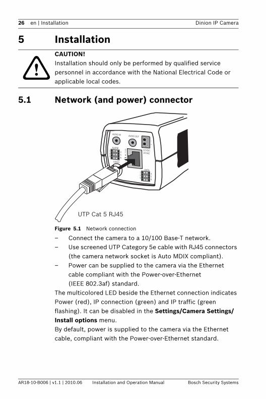
Figure 5.1 Network connection
– Connect the camera to a 10/100 Base-T network.– Use screened UTP Category 5e cable with RJ45 connectors
(the camera network socket is Auto MDIX compliant).– Power can be supplied to the camera via the Ethernet
cable compliant with the Power-over-Ethernet (IEEE 802.3af) standard.
The multicolored LED beside the Ethernet connection indicates Power (red), IP connection (green) and IP traffic (green flashing). It can be disabled in the Settings/Camera Settings/Install options menu.By default, power is supplied to the camera via the Ethernet cable, compliant with the Power-over-Ethernet standard.
CAUTION! Installation should only be performed by qualified service personnel in accordance with the National Electrical Code or applicable local codes.
UTP Cat 5 RJ45
123
456
ETH
PoE
ALARM
AUDIO IN AUDIO OUT
VIDEO
DATA123
456
–
+
12 VDC24 VAC
Dinion IP Camera Installation | en 27
Bosch Security Systems Installation and Operation Manual AR18-10-B006 | v1.1 | 2010.06
5.2 Power connector
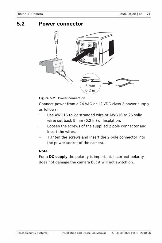
Figure 5.2 Power connection
Connect power from a 24 VAC or 12 VDC class 2 power supply as follows:– Use AWG16 to 22 stranded wire or AWG16 to 26 solid
wire; cut back 5 mm (0.2 in) of insulation.– Loosen the screws of the supplied 2-pole connector and
insert the wires. – Tighten the screws and insert the 2-pole connector into
the power socket of the camera.
Note:For a DC supply the polarity is important. Incorrect polarity does not damage the camera but it will not switch on.
123
456
ETH
PoE
ALARM
AUDIO IN AUDIO OUT
VIDEO
DATA123
456
–
+
12 VDC24 VAC
5 mm0.2 in
28 en | Installation Dinion IP Camera
AR18-10-B006 | v1.1 | 2010.06 Installation and Operation Manual Bosch Security Systems
5.3 Alarm and relay connector
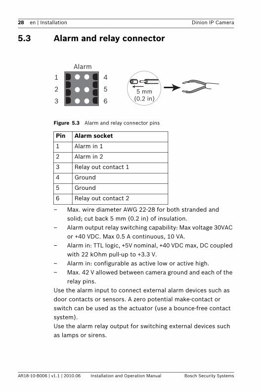
Figure 5.3 Alarm and relay connector pins
– Max. wire diameter AWG 22-28 for both stranded and solid; cut back 5 mm (0.2 in) of insulation.
– Alarm output relay switching capability: Max voltage 30VAC or +40 VDC. Max 0.5 A continuous, 10 VA.
– Alarm in: TTL logic, +5V nominal, +40 VDC max, DC coupled with 22 kOhm pull-up to +3.3 V.
– Alarm in: configurable as active low or active high.– Max. 42 V allowed between camera ground and each of the
relay pins.Use the alarm input to connect external alarm devices such as door contacts or sensors. A zero potential make-contact or switch can be used as the actuator (use a bounce-free contact system).Use the alarm relay output for switching external devices such as lamps or sirens.
Pin Alarm socket
1 Alarm in 1
2 Alarm in 2
3 Relay out contact 1
4 Ground
5 Ground
6 Relay out contact 2
Alarm
1
2
3
4
5
65 mm
(0.2 in)
Dinion IP Camera Installation | en 29
Bosch Security Systems Installation and Operation Manual AR18-10-B006 | v1.1 | 2010.06
5.4 Audio connectors
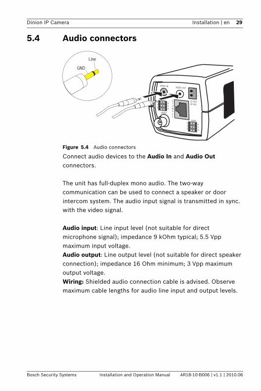
Figure 5.4 Audio connectors
Connect audio devices to the Audio In and Audio Out connectors.
The unit has full-duplex mono audio. The two-way communication can be used to connect a speaker or door intercom system. The audio input signal is transmitted in sync. with the video signal.
Audio input: Line input level (not suitable for direct microphone signal); impedance 9 kOhm typical; 5.5 Vpp maximum input voltage.Audio output: Line output level (not suitable for direct speaker connection); impedance 16 Ohm minimum; 3 Vpp maximum output voltage.Wiring: Shielded audio connection cable is advised. Observe maximum cable lengths for audio line input and output levels.
123
456
ETH
PoE
ALARM
AUDIO IN AUDIO OUT
VIDEO
DATA123
456
–
+
12 VDC24 VAC
GND
Line
30 en | Installation Dinion IP Camera
AR18-10-B006 | v1.1 | 2010.06 Installation and Operation Manual Bosch Security Systems
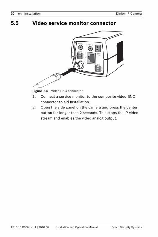
5.5 Video service monitor connector
Figure 5.5 Video BNC connector
1. Connect a service monitor to the composite video BNC connector to aid installation.
2. Open the side panel on the camera and press the center button for longer than 2 seconds. This stops the IP video stream and enables the video analog output.
123
456
ETH
PoE
ALARM
AUDIO IN AUDIO OUT
VIDEO
DATA123
456
–
+
12 VDC24 VAC
Dinion IP Camera Installation | en 31
Bosch Security Systems Installation and Operation Manual AR18-10-B006 | v1.1 | 2010.06
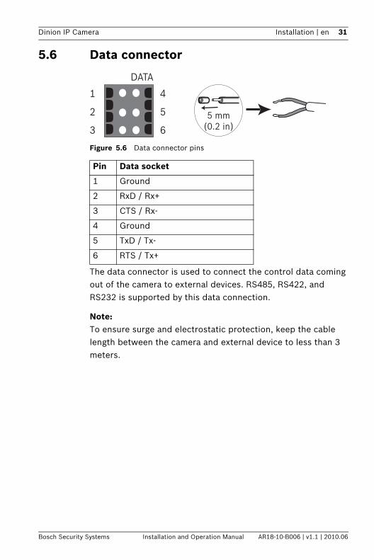
5.6 Data connector
Figure 5.6 Data connector pins
The data connector is used to connect the control data coming out of the camera to external devices. RS485, RS422, and RS232 is supported by this data connection.
Note:To ensure surge and electrostatic protection, keep the cable length between the camera and external device to less than 3 meters.
Pin Data socket
1 Ground
2 RxD / Rx+
3 CTS / Rx-
4 Ground
5 TxD / Tx-
6 RTS / Tx+
DATA
1
2
3
4
5
65 mm
(0.2 in)
32 en | Installation Dinion IP Camera
AR18-10-B006 | v1.1 | 2010.06 Installation and Operation Manual Bosch Security Systems
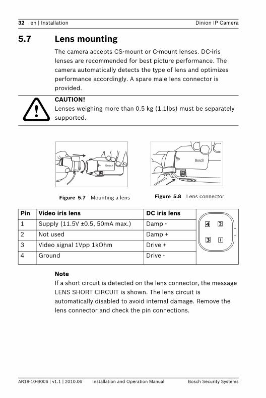
5.7 Lens mountingThe camera accepts CS-mount or C-mount lenses. DC-iris lenses are recommended for best picture performance. The camera automatically detects the type of lens and optimizes performance accordingly. A spare male lens connector is provided.
NoteIf a short circuit is detected on the lens connector, the message LENS SHORT CIRCUIT is shown. The lens circuit is automatically disabled to avoid internal damage. Remove the lens connector and check the pin connections.
CAUTION! Lenses weighing more than 0.5 kg (1.1lbs) must be separately supported.
Figure 5.7 Mounting a lens Figure 5.8 Lens connector
Bosch
Bosch
Pin Video iris lens DC iris lens
1 Supply (11.5V ±0.5, 50mA max.) Damp -
2 Not used Damp +
3 Video signal 1Vpp 1kOhm Drive +
4 Ground Drive -
Dinion IP Camera Installation | en 33
Bosch Security Systems Installation and Operation Manual AR18-10-B006 | v1.1 | 2010.06
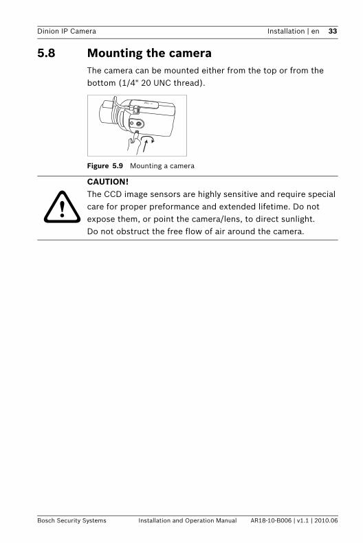
5.8 Mounting the camera The camera can be mounted either from the top or from the bottom (1/4" 20 UNC thread).
Figure 5.9 Mounting a camera
CAUTION! The CCD image sensors are highly sensitive and require special care for proper preformance and extended lifetime. Do not expose them, or point the camera/lens, to direct sunlight.Do not obstruct the free flow of air around the camera.
34 en | Installation Dinion IP Camera
AR18-10-B006 | v1.1 | 2010.06 Installation and Operation Manual Bosch Security Systems
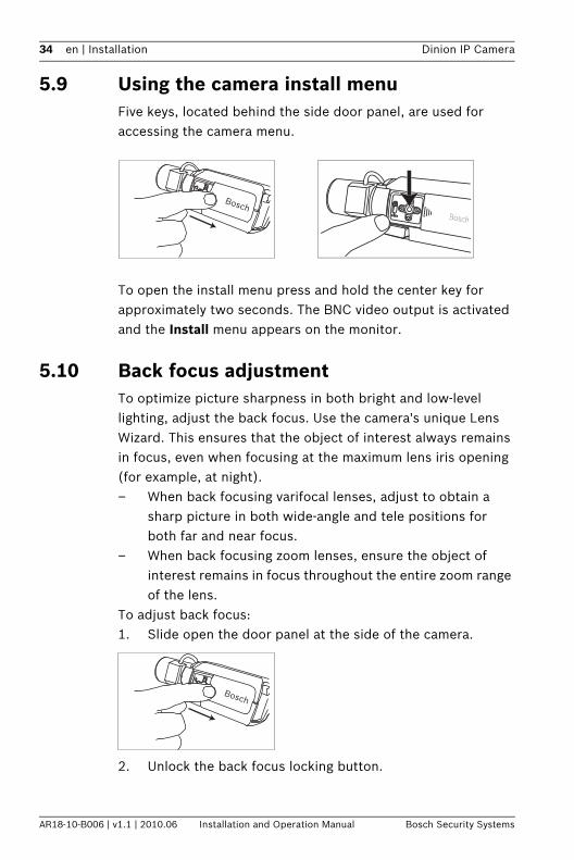
5.9 Using the camera install menuFive keys, located behind the side door panel, are used for accessing the camera menu.
To open the install menu press and hold the center key for approximately two seconds. The BNC video output is activated and the Install menu appears on the monitor.
5.10 Back focus adjustmentTo optimize picture sharpness in both bright and low-level lighting, adjust the back focus. Use the camera's unique Lens Wizard. This ensures that the object of interest always remains in focus, even when focusing at the maximum lens iris opening (for example, at night).– When back focusing varifocal lenses, adjust to obtain a
sharp picture in both wide-angle and tele positions for both far and near focus.
– When back focusing zoom lenses, ensure the object of interest remains in focus throughout the entire zoom range of the lens.
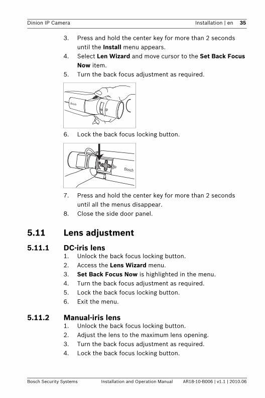
To adjust back focus:1. Slide open the door panel at the side of the camera.
2. Unlock the back focus locking button.
BoschBosch
Bosch
Dinion IP Camera Installation | en 35
Bosch Security Systems Installation and Operation Manual AR18-10-B006 | v1.1 | 2010.06
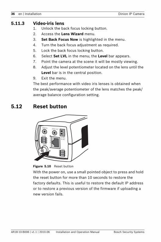
3. Press and hold the center key for more than 2 seconds until the Install menu appears.
4. Select Len Wizard and move cursor to the Set Back Focus Now item.
5. Turn the back focus adjustment as required.
6. Lock the back focus locking button.
7. Press and hold the center key for more than 2 seconds until all the menus disappear.
8. Close the side door panel.
5.11 Lens adjustment
5.11.1 DC-iris lens1. Unlock the back focus locking button.2. Access the Lens Wizard menu.3. Set Back Focus Now is highlighted in the menu.4. Turn the back focus adjustment as required.5. Lock the back focus locking button.6. Exit the menu.
5.11.2 Manual-iris lens1. Unlock the back focus locking button.2. Adjust the lens to the maximum lens opening.3. Turn the back focus adjustment as required.4. Lock the back focus locking button.
Bosch
Bosch
36 en | Installation Dinion IP Camera
AR18-10-B006 | v1.1 | 2010.06 Installation and Operation Manual Bosch Security Systems
5.11.3 Video-iris lens1. Unlock the back focus locking button.2. Access the Lens Wizard menu.3. Set Back Focus Now is highlighted in the menu.4. Turn the back focus adjustment as required.5. Lock the back focus locking button.6. Select Set LVL in the menu; the Level bar appears.7. Point the camera at the scene it will be mostly viewing.8. Adjust the level potentiometer located on the lens until the
Level bar is in the central position.9. Exit the menu.The best performance with video iris lenses is obtained when the peak/average potentiometer of the lens matches the peak/average balance configuration setting.
5.12 Reset button
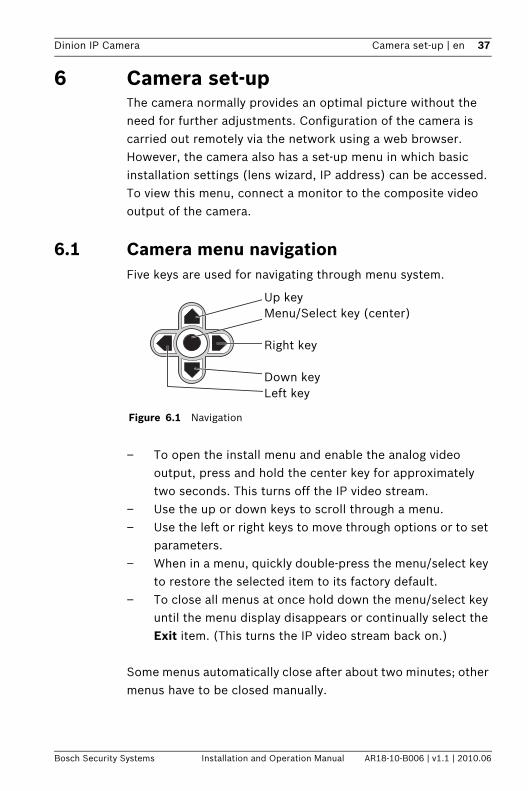
Figure 5.10 Reset button
With the power on, use a small pointed object to press and hold the reset button for more than 10 seconds to restore the factory defaults. This is useful to restore the default IP address or to restore a previous version of the firmware if uploading a new version fails.
123
456
ETH
PoE
ALARM
AUDIO IN AUDIO OUT
VIDEO
DATA123
456
–
+
12 VDC24 VAC
Dinion IP Camera Camera set-up | en 37
Bosch Security Systems Installation and Operation Manual AR18-10-B006 | v1.1 | 2010.06
6 Camera set-upThe camera normally provides an optimal picture without the need for further adjustments. Configuration of the camera is carried out remotely via the network using a web browser. However, the camera also has a set-up menu in which basic installation settings (lens wizard, IP address) can be accessed. To view this menu, connect a monitor to the composite video output of the camera.
6.1 Camera menu navigationFive keys are used for navigating through menu system.
– To open the install menu and enable the analog video output, press and hold the center key for approximately two seconds. This turns off the IP video stream.
– Use the up or down keys to scroll through a menu.– Use the left or right keys to move through options or to set
parameters.– When in a menu, quickly double-press the menu/select key
to restore the selected item to its factory default.– To close all menus at once hold down the menu/select key
until the menu display disappears or continually select the Exit item. (This turns the IP video stream back on.)
Some menus automatically close after about two minutes; other menus have to be closed manually.
Figure 6.1 Navigation
Up keyMenu/Select key (center)
Right key
Down keyLeft key
38 en | Camera set-up Dinion IP Camera
AR18-10-B006 | v1.1 | 2010.06 Installation and Operation Manual Bosch Security Systems
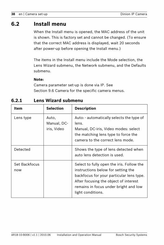
6.2 Install menuWhen the Install menu is opened, the MAC address of the unit is shown. This is factory set and cannot be changed. (To ensure that the correct MAC address is displayed, wait 20 seconds after power-up before opening the Install menu.)
The items in the Install menu include the Mode selection, the Lens Wizard submenu, the Network submenu, and the Defaults submenu.
Note:Camera parameter set-up is done via IP. See Section 9.6 Camera for the specific camera menus.
6.2.1 Lens Wizard submenu
Item Selection Description
Lens type Auto, Manual, DC-iris, Video
Auto: - automatically selects the type of lens.Manual, DC-iris, Video modes: select the matching lens type to force the camera to the correct lens mode.
Detected Shows the type of lens detected when auto lens detection is used.
Set Backfocus now
Select to fully open the iris. Follow the instructions below for setting the backfocus for your particular lens type.After focusing the object of interest remains in focus under bright and low light conditions.
Dinion IP Camera Camera set-up | en 39
Bosch Security Systems Installation and Operation Manual AR18-10-B006 | v1.1 | 2010.06
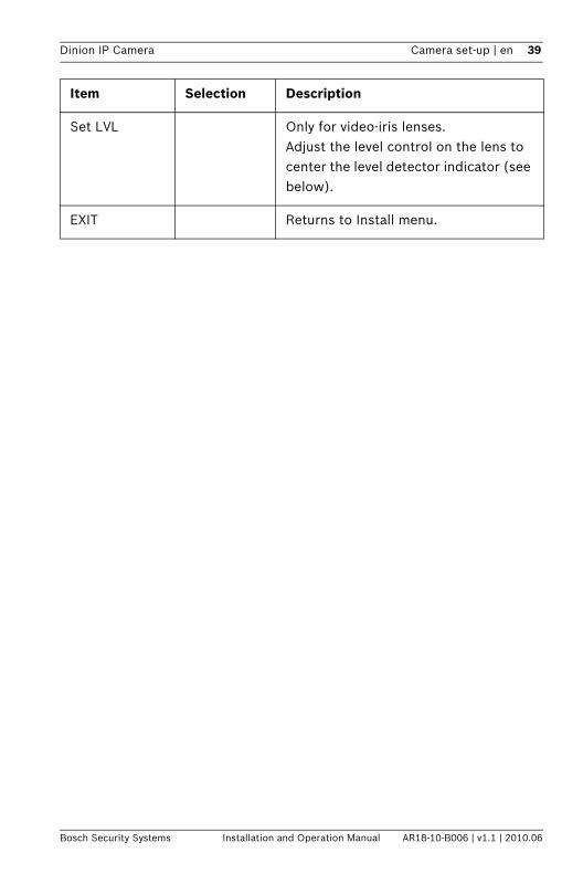
Set LVL Only for video-iris lenses.Adjust the level control on the lens to center the level detector indicator (see below).
EXIT Returns to Install menu.
Item Selection Description
40 en | Camera set-up Dinion IP Camera
AR18-10-B006 | v1.1 | 2010.06 Installation and Operation Manual Bosch Security Systems
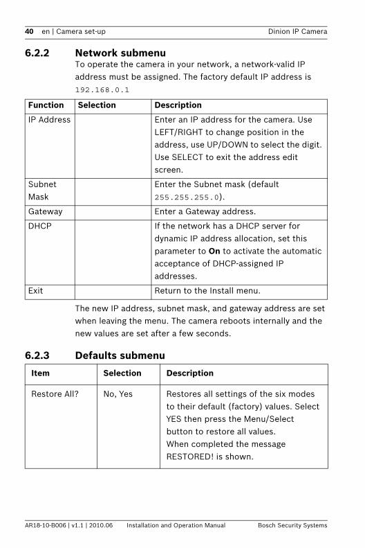
6.2.2 Network submenuTo operate the camera in your network, a network-valid IP address must be assigned. The factory default IP address is 192.168.0.1
The new IP address, subnet mask, and gateway address are set when leaving the menu. The camera reboots internally and the new values are set after a few seconds.
6.2.3 Defaults submenu
Function Selection Description
IP Address Enter an IP address for the camera. Use LEFT/RIGHT to change position in the address, use UP/DOWN to select the digit. Use SELECT to exit the address edit screen.
Subnet Mask
Enter the Subnet mask (default 255.255.255.0).
Gateway Enter a Gateway address.
DHCP If the network has a DHCP server for dynamic IP address allocation, set this parameter to On to activate the automatic acceptance of DHCP-assigned IP addresses.
Exit Return to the Install menu.
Item Selection Description
Restore All? No, Yes Restores all settings of the six modes to their default (factory) values. Select YES then press the Menu/Select button to restore all values. When completed the message RESTORED! is shown.
Dinion IP Camera Browser connection | en 41
Bosch Security Systems Installation and Operation Manual AR18-10-B006 | v1.1 | 2010.06
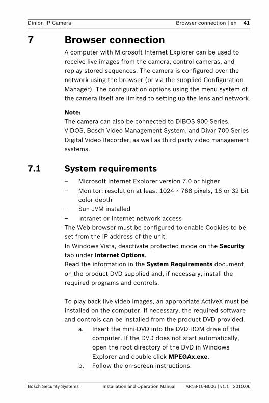
7 Browser connectionA computer with Microsoft Internet Explorer can be used to receive live images from the camera, control cameras, and replay stored sequences. The camera is configured over the network using the browser (or via the supplied Configuration Manager). The configuration options using the menu system of the camera itself are limited to setting up the lens and network.
Note:The camera can also be connected to DIBOS 900 Series, VIDOS, Bosch Video Management System, and Divar 700 Series Digital Video Recorder, as well as third party video management systems.
7.1 System requirements – Microsoft Internet Explorer version 7.0 or higher– Monitor: resolution at least 1024 × 768 pixels, 16 or 32 bit
color depth– Sun JVM installed– Intranet or Internet network accessThe Web browser must be configured to enable Cookies to be set from the IP address of the unit.In Windows Vista, deactivate protected mode on the Security tab under Internet Options.Read the information in the System Requirements document on the product DVD supplied and, if necessary, install the required programs and controls.
To play back live video images, an appropriate ActiveX must be installed on the computer. If necessary, the required software and controls can be installed from the product DVD provided.
a. Insert the mini-DVD into the DVD-ROM drive of the computer. If the DVD does not start automatically, open the root directory of the DVD in Windows Explorer and double click MPEGAx.exe.
b. Follow the on-screen instructions.
42 en | Browser connection Dinion IP Camera
AR18-10-B006 | v1.1 | 2010.06 Installation and Operation Manual Bosch Security Systems
7.2 Establishing the connectionThe camera must be assigned a valid IP address to operate on your network. The default address pre-set at the factory is 192.168.0.1
1. Start the Web browser.2. Enter the IP address of the camera as the URL.
Note:If the connection is not established, the maximum number of possible connections may already have been reached. Depending on the device and network configuration, up to 25 web browsers, or 50 VIDOS or Bosch VMS connections are supported.
7.2.1 Password protection in cameraA camera offers the option of limiting access across various authorization levels. If the camera is password-protected, a message to enter the password appears. 1. Enter the user name and the associated password in the
appropriate fields.2. Click OK. If the password is correct, the desired page is
displayed.
7.3 Protected networkIf a Radius server is used for network access control (802.1x authentication), the camera must be configured first. To configure the camera for a Radius network, connect it directly to a PC via a crossed network cable and configure the two parameters, Identity and Password. Only after these have been configured can communication with the camera via the network occur.
Dinion IP Camera Browser connection | en 43
Bosch Security Systems Installation and Operation Manual AR18-10-B006 | v1.1 | 2010.06
7.4 Connecting to a hardware decoderA compatible H.264 hardware decoder with a monitor can be connected to the camera using an Ethernet network connection. Cameras are designed to automatically connect with other BVIP devices with the correct configuration. The units only need to be part of the same closed network. In this way it is possible to cover large distances with little installation or cabling effort.
7.4.1 Alarm connectionWith the appropriate configuration, a connection between camera and decoder is established automatically when an alarm is triggered. After a short time, the live video image from the transmitter is shown on the connected monitor. In this case, no computer is needed to establish the connection
Note:Make sure the devices are configured for the network environment and that the correct IP address for the remote location is set on the Alarm connections configuration page.
44 en | Browser connection Dinion IP Camera
AR18-10-B006 | v1.1 | 2010.06 Installation and Operation Manual Bosch Security Systems
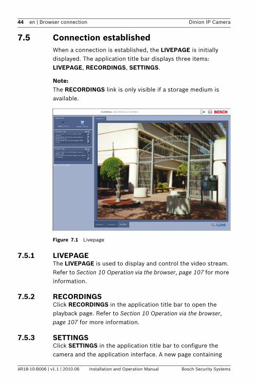
7.5 Connection establishedWhen a connection is established, the LIVEPAGE is initially displayed. The application title bar displays three items: LIVEPAGE, RECORDINGS, SETTINGS.
Note:The RECORDINGS link is only visible if a storage medium is available.
Figure 7.1 Livepage
7.5.1 LIVEPAGEThe LIVEPAGE is used to display and control the video stream. Refer to Section 10 Operation via the browser, page 107 for more information.
7.5.2 RECORDINGSClick RECORDINGS in the application title bar to open the playback page. Refer to Section 10 Operation via the browser, page 107 for more information.
7.5.3 SETTINGSClick SETTINGS in the application title bar to configure the camera and the application interface. A new page containing
Dinion IP Camera Browser connection | en 45
Bosch Security Systems Installation and Operation Manual AR18-10-B006 | v1.1 | 2010.06
the configuration menu is opened. All settings are stored in the camera memory so that they are retained, even if the power is interrupted.Changes that influence the fundamental functioning of the unit (for example, firmware updates) can only be made using the configuration menu.The configuration menu tree allows all parameters of the unit to be configured. The configuration menu is divided into Basic Mode and Advanced Mode. Refer to Section 8 Basic Mode, page 46 for more information on basic settings; refer to Section 9 Advanced Mode, page 51 for more information on advanced settings.
Note:It is recommended that only expert users or system administrators use the Advanced Mode.
46 en | Basic Mode Dinion IP Camera
AR18-10-B006 | v1.1 | 2010.06 Installation and Operation Manual Bosch Security Systems
8 Basic Mode
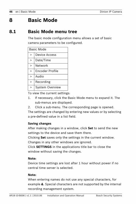
8.1 Basic Mode menu treeThe basic mode configuration menu allows a set of basic camera parameters to be configured.
To view the current settings:1. If necessary, click the Basic Mode menu to expand it. The
sub-menus are displayed.2. Click a sub-menu. The corresponding page is opened.The settings are changed by entering new values or by selecting a pre-defined value in a list field.
Saving changesAfter making changes in a window, click Set to send the new settings to the device and save them there.Clicking Set saves only the settings in the current window. Changes in any other windows are ignored.Click SETTINGS in the applications title bar to close the window without saving the changes.
Note:Device time settings are lost after 1 hour without power if no central time server is selected.
Note:When entering names do not use any special characters, for example &. Special characters are not supported by the internal recording management system.
Basic Mode
> Device Access
> Date/Time
> Network
> Encoder Profile
> Audio
> Recording
> System Overview
Dinion IP Camera Basic Mode | en 47
Bosch Security Systems Installation and Operation Manual AR18-10-B006 | v1.1 | 2010.06
8.2 Device Access
8.2.1 Camera nameAssign a name to assist in identification. This name simplifies the management of multiple devices in more extensive systems.The name is used for remote identification, for example, in the event of an alarm. Enter a name that makes it as easy as possible to identify the location unambiguously.
8.2.2 PasswordA password prevents unauthorized access to the device. The device recognizes three authorization levels: service, user, and live.– service is the highest authorization level. Entering the
correct password gives access to all the functions of the camera and allows all configuration settings to be changed.
– user is the middle authorization level. This user can operate the device, play back recordings, and also control a camera but cannot change the configuration.
– live is the lowest authorization level. It can only be used to view the live video image and switch between the different live image displays.
Use the various authorization levels to limit access. Proper password protection is only guaranteed if all higher authorization levels are also protected with a password. For example, if a live password is assigned, a service and a user password should also be set. When assigning passwords, always start from the highest authorization level, service, and use different passwords.
PasswordDefine and change a separate password for each level while logged in as service or if the device is not protected by a password. Enter the password for the selected level.
48 en | Basic Mode Dinion IP Camera
AR18-10-B006 | v1.1 | 2010.06 Installation and Operation Manual Bosch Security Systems
Confirm passwordRe-enter the new password to ensure that there are no typing mistakes.The new password is only saved after clicking Set. Therefore, click Set immediately after entering and confirming the password, even if assigning a password at another level.
8.3 Date/TimeDevice date, time and zoneIf there are multiple devices operating in the system or network, it is important to synchronize their internal clocks. For example, it is only possible to identify and correctly evaluate simultaneous recordings when all devices are operating on the same time.As the device time is controlled by the internal clock, it is not necessary to enter the day or date of the week. These are set automatically. The time zone in which the system is located is also set automatically.1. Click Sync to PC to apply the system time from your
computer to the device.
Time server IP addressThe camera can receive the time signal from a time server using various time server protocols and then use it to set the internal clock. The device polls the time signal automatically once every minute. Enter the IP address of a time server.
Time server typeSelect the protocol that is supported by the selected time server. It is recommended to select the SNTP server protocol. This protocol provides high accuracy and is required for special applications and future function extensions. Select Time server if the server uses the RFC 868 protocol.
Note:It is important to ensure that the date/time is correct for recording. An incorrect date/time setting could prevent correct recording.
Dinion IP Camera Basic Mode | en 49
Bosch Security Systems Installation and Operation Manual AR18-10-B006 | v1.1 | 2010.06
8.4 NetworkUse the settings on this page to integrate the device into a network. Some changes only take effect after a reboot. In this case, the Set button changes to Set and Reboot.1. Make the desired changes.2. Click Set and Reboot.
– The device is rebooted and the changed settings are activated. If the IP address, subnet mask, or gateway address is changed, then the device is only available under the new addresses after the reboot.
DHCPIf the network has a DHCP server for dynamic IP address allocation, set this parameter to On to activate the automatic acceptance of DHCP-assigned IP addresses.
Note:Certain applications (for example, Bosch Video Management System) use the IP address for the unique assignment of the device. If using these applications, the DHCP server must support the fixed assignment between IP address and MAC address, and must be appropriately set up so that, once an IP address is assigned, it is retained each time the system is rebooted.
IP addressEnter the desired IP address for the camera. The IP address must be valid for the network.
Subnet maskEnter the appropriate subnet mask for the set IP address.
Gateway addressEnter the IP address of the gateway to establish a connection to a remote location in a different subnet. Otherwise, this field can remain empty (0.0.0.0).
50 en | Basic Mode Dinion IP Camera
AR18-10-B006 | v1.1 | 2010.06 Installation and Operation Manual Bosch Security Systems
8.5 Encoder ProfileSelect a profile for encoding the video signal. Pre-programmed profiles are available that give priority to different parameters. When a profile is selected, its details are displayed.
8.6 AudioSwitch the camera audio On or Off. Adjust the input and output levels with the sliders.
8.7 RecordingRecord the images from the camera to a storage medium. For long-term authoritative images, it is essential to use a Divar 700 Series Digital Video Recorder or an appropriately sized iSCSI system.
8.7.1 Storage medium1. Select the required storage medium from the list.2. Click Start to start recording or Stop to end recording.
8.8 System OverviewThis page provides general information on the hardware and firmware system, including version numbers. No items can be changed on this page but they can be copied for information purposes when troubleshooting.
Dinion IP Camera Advanced Mode | en 51
Bosch Security Systems Installation and Operation Manual AR18-10-B006 | v1.1 | 2010.06
9 Advanced Mode
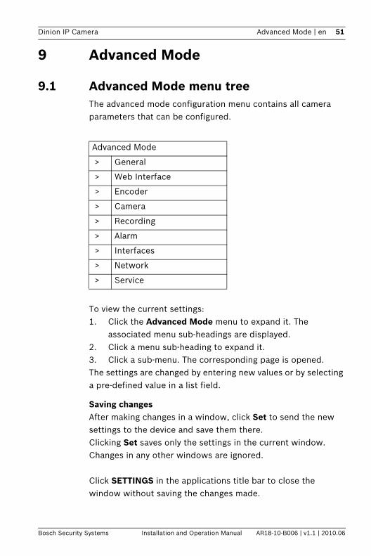
9.1 Advanced Mode menu treeThe advanced mode configuration menu contains all camera parameters that can be configured.
To view the current settings:1. Click the Advanced Mode menu to expand it. The
associated menu sub-headings are displayed.2. Click a menu sub-heading to expand it.3. Click a sub-menu. The corresponding page is opened.The settings are changed by entering new values or by selecting a pre-defined value in a list field.
Saving changesAfter making changes in a window, click Set to send the new settings to the device and save them there.Clicking Set saves only the settings in the current window. Changes in any other windows are ignored.
Click SETTINGS in the applications title bar to close the window without saving the changes made.
Advanced Mode
> General
> Web Interface
> Encoder
> Camera
> Recording
> Alarm
> Interfaces
> Network
> Service
52 en | Advanced Mode Dinion IP Camera
AR18-10-B006 | v1.1 | 2010.06 Installation and Operation Manual Bosch Security Systems
Note:Device time settings are lost after 1 hour without power if no central time server is selected.
Note:When entering names do not use any special characters, for example &. Special characters are not supported by the internal recording management system.
Dinion IP Camera Advanced Mode | en 53
Bosch Security Systems Installation and Operation Manual AR18-10-B006 | v1.1 | 2010.06
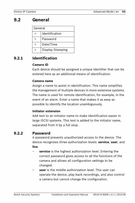
9.2 General
9.2.1 Identification
Camera IDEach device should be assigned a unique identifier that can be entered here as an additional means of identification.
Camera nameAssign a name to assist in identification. This name simplifies the management of multiple devices in more extensive systems. The name is used for remote identification, for example, in the event of an alarm. Enter a name that makes it as easy as possible to identify the location unambiguously.
Initiator extensionAdd text to an initiator name to make identification easier in large iSCSI systems. This text is added to the initiator name, separated from it by a full stop.
9.2.2 PasswordA password prevents unauthorized access to the device. The device recognizes three authorization levels: service, user, and live.– service is the highest authorization level. Entering the
correct password gives access to all the functions of the camera and allows all configuration settings to be changed.
– user is the middle authorization level. This user can operate the device, play back recordings, and also control a camera but cannot change the configuration.
General
> Identification
> Password
> Date/Time
> Display Stamping
54 en | Advanced Mode Dinion IP Camera
AR18-10-B006 | v1.1 | 2010.06 Installation and Operation Manual Bosch Security Systems
– live is the lowest authorization level. It can only be used to view the live video image and switch between the different live image displays.
Use the various authorization levels to limit access. Proper password protection is only guaranteed if all higher authorization levels are also protected with a password. For example, if a live password is assigned, a service and a user password should also be set. When assigning passwords, always start from the highest authorization level, service, and use different passwords.
PasswordDefine and change a separate password for each level while logged in as service or if the device is not protected by a password. Enter the password for the selected level.
Confirm passwordRe-enter the new password to ensure that there are no typing mistakes.The new password is only saved after clicking Set. Therefore, click Set immediately after entering and confirming the password, even if assigning a password at another level.
9.2.3 Date/Time
Date formatSelect the required date format.
Device date / Device timeIf there are multiple devices operating in your system or network, it is important to synchronize their internal clocks. For example, it is only possible to identify and correctly evaluate simultaneous recordings when all devices are operating on the same time.1. Enter the current date. Since the device time is controlled
by the internal clock, it is not necessary to enter the day of the week – it is added automatically.
Dinion IP Camera Advanced Mode | en 55
Bosch Security Systems Installation and Operation Manual AR18-10-B006 | v1.1 | 2010.06
2. Enter the current time or click Sync to PC to apply the system time from your computer to the device.
Note:It is important to ensure that the date/time is correct for recording. An incorrect date/time setting could prevent correct recording.
Device time zoneSelect the time zone in which the system is located.
Daylight saving timeThe internal clock can switch automatically between normal and daylight saving time (DST). The device already contains the data for DST switch-overs up to the year 2015. Use this data or create alternative time saving data, if required.Note:If a table is not created, there is no automatic switching. When editing the table, note that values occur in linked pairs (DST start and end dates).
First, check the time zone setting. If it is not correct, select the appropriate time zone for the system:1. Click Set.2. Click Details. A new window opens showing an empty
table.3. Click Generate to fill the table with the preset values from
the camera.4. Select the region or the city which is closest to the
system's location from the list box below the table.5. Click one of the entries in the table to make changes. The
entry is highlighted.6. Click Delete to remove the entry from the table.7. Choose other values from the list boxes under the table, to
change the selected entry. Changes are immediate.8. If there are empty lines at the bottom of the table, for
example after deletions, add new data by marking the row and selecting values from the list boxes.
56 en | Advanced Mode Dinion IP Camera
AR18-10-B006 | v1.1 | 2010.06 Installation and Operation Manual Bosch Security Systems
9. When finished, click OK to save and activate the table.
Time server IP addressThe camera can receive the time signal from a time server using various time server protocols and then use it to set the internal clock. The device polls the time signal automatically once every minute. Enter the IP address of a time server.
Time server typeSelect the protocol that is supported by the selected time server. It is recommended to select the SNTP server protocol. This protocol provides high accuracy and is required for special applications and future function extensions. Select Time server if the server uses the RFC 868 protocol.
9.2.4 Display StampingVarious overlays or stamps in the video image provide important supplementary information. These overlays can be enabled individually and arranged on the image in a clear manner.
Camera name stampingThis field sets the position of the camera name overlay. It can be displayed at the Top, at the Bottom, or at a position of choice using the Custom option, or it can be set to Off for no overlay information.If the Custom option is selected, enter values in the X and Y position fields.
Time stampingThis field sets the position of the time and date overlay. It can be displayed at the Top, at the Bottom, or at a position of choice using the Custom option, or it can be set to Off for no overlay information.If the Custom option is selected, enter values in the X and Y position fields.
Display millisecondsIf necessary, display milliseconds for Time stamping. This information can be useful for recorded video images; however,
Dinion IP Camera Advanced Mode | en 57
Bosch Security Systems Installation and Operation Manual AR18-10-B006 | v1.1 | 2010.06
it does increase the processor's computing time. Select Off if displaying milliseconds is not needed.
Alarm mode stampingSelect On for a text message to be overlaid in the event of an alarm. It can be displayed at a position of choice using the Custom option, or it can be set to Off for no overlay information.If the Custom option is selected, enter values in the X and Y position fields.
Alarm messageEnter the message to be displayed on the image in the event of an alarm. The maximum text length is 31 characters.
Video watermarkingSelect On for the transmitted video images to be watermarked. After activation, all images are marked with a green W. A red W indicates that the sequence (live or saved) has been manipulated.
58 en | Advanced Mode Dinion IP Camera
AR18-10-B006 | v1.1 | 2010.06 Installation and Operation Manual Bosch Security Systems
9.3 Web Interface
9.3.1 AppearanceAdapt the appearance of the web interface and change the website language to meet your requirements. If necessary, replace the company's logo (top right) and the device name (top left) in the top part of the window with individual graphics.Either GIF or JPEG images can be used. The file paths must correspond to the access mode (for example, C:\Images\Logo.gif for access to local files or http://www.myhostname.com/images/logo.gif for access via the Internet/Intranet). For access via the Internet/Intranet, there must be a connection in order to display the image. The image files are not stored on the camera.To restore the original graphics, delete the entries in the Company logo and Device logo fields.
Website languageSelect the language for the user interface here.
Company logoEnter the path to a suitable image in this field. The image can be stored on a local computer, a local network, or at an Internet address.
Device logoEnter the path for a suitable image for the device logo in this field. The image can be stored on a local computer, a local network, or at an Internet address.
JPEG intervalSpecify the interval at which the individual images should be generated for the M-JPEG image on the Livepage.
Web Interface
> Appearance
> LIVEPAGE Functions
> Logging
Dinion IP Camera Advanced Mode | en 59
Bosch Security Systems Installation and Operation Manual AR18-10-B006 | v1.1 | 2010.06
9.3.2 LIVEPAGE FunctionsIn this window, adapt the Livepage functions to meet your requirements. Choose from a variety of different options for displaying information and controls.1. Mark the check boxes for the functions to be displayed on
the Livepage. The selected elements are checked.2. Check the Livepage to see how the desired items are
available.
Transmit audioWhen selected, the audio from the camera (if on) is sent to the computer.
Show alarm inputsThe alarm inputs are displayed next to the video image as icons along with their assigned names. If an alarm is active, the corresponding icon changes color.
Show relay outputsThe relay output is shown next to the video image as an icon along with its assigned name. If a relay is switched, the icon changes color.
Show VCA trajectoriesThe trajectories (motion lines of objects) from the video content analysis are displayed in the live video image if a corresponding analysis type is activated.
Show VCA metadataWhen video content analysis (VCA) is activated, additional information is displayed in the live video stream. For example, in Motion+ mode, the sensor areas for motion detection are marked.
Show event logThe event messages are displayed with the date and time in a field next to the video image.
60 en | Advanced Mode Dinion IP Camera
AR18-10-B006 | v1.1 | 2010.06 Installation and Operation Manual Bosch Security Systems
Show system logThe system messages are displayed with the date and time in a field next to the video image and provide information about the establishment and termination of connections, etc.
Allow snapshotsSpecify whether the icon for saving individual images should be displayed below the live image. Individual images can only be saved if this icon is visible.
Allow local recordingSpecify whether the icon for saving video sequences on the local memory should be displayed below the live image. Video sequences can only be saved if this icon is visible.
Path for JPEG and video filesEnter the path for the storage location of individual images and video sequences saved from the Livepage. If necessary, click Browse to find a suitable folder.
9.3.3 Logging
Save event logSelect this option to save event messages in a text file on the local computer. This file can be viewed, edited, and printed with any text editor or standard office software.
File for event logEnter the path for saving the event log here. If necessary, click Browse to find a suitable folder.
Save system logSelect this option to save system messages in a text file on the local computer. This file can be viewed, edited, and printed with any text editor or standard office software.
File for system logEnter the path for saving the system log here. If necessary, click Browse to find a suitable folder.
Dinion IP Camera Advanced Mode | en 61
Bosch Security Systems Installation and Operation Manual AR18-10-B006 | v1.1 | 2010.06
9.4 Encoder
9.4.1 Privacy MasksFour privacy mask areas can be defined. The activated masked areas are filled with the selected pattern in live view.1. Select the pattern to be used for all masks (Gray). 2. Check the box of the mask you wish to activate.3. Use the mouse to define the area for each of the masks.
9.4.2 Encoder ProfileAdapt the video data transmission to the operating environment (network structure, bandwidth, data structures). The camera simultaneously generates two H.264 video streams and an M-JPEG stream (Tri-streaming). Select the compression settings of these streams individually, for example, one setting for transmissions to the Internet and one for LAN connections. The settings are made individually for each stream.
Define profilesEight definable profiles are available. The pre-programmed profiles give priority to different parameters.– High resolution 1
High resolution (4CIF/D1) for high bandwidth connections– High resolution 2
High resolution (4CIF/D1) with lower data rate– Low bandwidth
High resolution (4CIF/D1) for low bandwidth connections– DSL
High resolution (4CIF/D1) for DSL connections at 500 kbps maximum
Encoder
> Privacy Masks
> Encoder Profile
> Encoder Streams
> Audio
62 en | Advanced Mode Dinion IP Camera
AR18-10-B006 | v1.1 | 2010.06 Installation and Operation Manual Bosch Security Systems
– ISDN (2B)CIF resolution for ISDN connections at 100 kbps maximum
– ISDN (1B)CIF resolution for ISDN connections at 50 kbps maximum
– MODEMCIF resolution for analog modem connections at 22 kbps maximum
– GSMCIF resolution for GSM connections
Profile ConfigurationProfiles can be configured for use with the H.264 settings of encoder streams. Select a profile by clicking the appropriate tab. Change the name of a profile and individual parameter values within a profile.Profiles are rather complex. They include a number of parameters that interact with one another, so it is generally best to use the default profiles. Only change a profile if completely familiar with all the configuration options.The parameters as a group constitute a profile and are dependent on one another. If a setting outside the permitted range for a parameter is entered, the nearest valid value is substituted when the settings are saved.
Profile nameEnter a new name for the profile here.
Target data rateTo optimize utilization of the bandwidth in the network, limit the data rate for the camera. The target data rate should be set according to the desired picture quality for typical scenes with no excessive motion.For complex images or frequent changes of image content due to frequent movements, this limit can temporarily be exceeded up to the value entered in the Maximum data rate field.
Maximum data rateThis maximum data rate is not exceeded under any circumstances. Depending on the video quality settings for the
Dinion IP Camera Advanced Mode | en 63
Bosch Security Systems Installation and Operation Manual AR18-10-B006 | v1.1 | 2010.06
I-frames and P-frames, this can result in individual images being skipped.The value entered here must be at least 10% higher than the value entered in the Target data rate field. If the value entered here is too low, it is automatically adjusted.
Encoding intervalThe Encoding interval slider determines the interval at which images are encoded and transmitted. This can be particularly advantageous with low bandwidths. The image rate in ips (images per second) is displayed next to the slider.
Video resolutionSelect the desired resolution for the video image. The following resolutions are available:– CIF
352 × 288/240 pixels– 4CIF/D1
704 × 576/480 pixels
Expert Settingsif necessary, use the expert settings to adapt the I-frame quality and the P-frame quality to specific requirements. The setting is based on the H.264 quantization parameter (QP).
I-frame qualityThis setting adjusts the image quality of the I-frames. The basic setting Auto automatically adjusts the quality to the settings for the P-frame video quality. Alternatively, use the slider to set a value between 9 and 51. The value 9 represents the best image quality with, if necessary, a lower frame refresh rate depending on the settings for the maximum data rate. A value of 51 results in a very high refresh rate and lower image quality.
P-frame qualityThis setting adjusts the maximum image quality of the P-frames. The basic setting Auto automatically adjusts to the optimum combination of movement and image definition (focus). Alternatively, use the slider to set a value between 9 and 51.
64 en | Advanced Mode Dinion IP Camera
AR18-10-B006 | v1.1 | 2010.06 Installation and Operation Manual Bosch Security Systems
The value 9 represents the best image quality with, if necessary, a lower frame refresh rate depending on the settings for the maximum data rate. A value of 51 results in a very high refresh rate and lower image quality.
DefaultClick Default to return the profile to the factory default values.
Dinion IP Camera Advanced Mode | en 65
Bosch Security Systems Installation and Operation Manual AR18-10-B006 | v1.1 | 2010.06
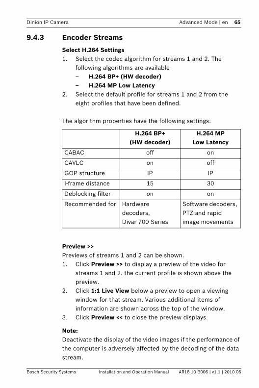
9.4.3 Encoder Streams
Select H.264 Settings1. Select the codec algorithm for streams 1 and 2. The
following algorithms are available– H.264 BP+ (HW decoder)– H.264 MP Low Latency
2. Select the default profile for streams 1 and 2 from the eight profiles that have been defined.
The algorithm properties have the following settings:
Preview >>Previews of streams 1 and 2 can be shown. 1. Click Preview >> to display a preview of the video for
streams 1 and 2. the current profile is shown above the preview.
2. Click 1:1 Live View below a preview to open a viewing window for that stream. Various additional items of information are shown across the top of the window.
3. Click Preview << to close the preview displays.
Note:Deactivate the display of the video images if the performance of the computer is adversely affected by the decoding of the data stream.
H.264 BP+ (HW decoder)
H.264 MP Low Latency
CABAC off on
CAVLC on off
GOP structure IP IP
I-frame distance 15 30
Deblocking filter on on
Recommended for Hardware decoders, Divar 700 Series
Software decoders, PTZ and rapid image movements
66 en | Advanced Mode Dinion IP Camera
AR18-10-B006 | v1.1 | 2010.06 Installation and Operation Manual Bosch Security Systems
JPEG streamSet the parmeters for the M-JPEG stream.– Select the Max. frame rate in images per second (IPS). – The Picture quality slider allows adjustment of the
M-JPEG image quality from Low to High.
Note:The JPEG resolution follows the highest resolution setting either in stream 1 or stream 2. For example, if stream 1 is 4CIF/D1 and stream 2 is CIF, the JPEG resolution will be 4CIF/D1.
9.5 AudioSwitch the camera audio On or Off. Adjust the input and output levels with the sliders.
Note:The audio signals are sent in a separate data stream parallel to the video data, and so increase the network load. The audio data requires an additional bandwidth of approximately 80 kbps for each connection. If you do not want any audio data to be transmitted, select Off.
Dinion IP Camera Advanced Mode | en 67
Bosch Security Systems Installation and Operation Manual AR18-10-B006 | v1.1 | 2010.06
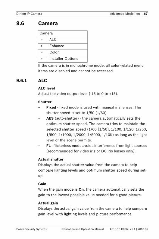
9.6 Camera
If the camera is in monochrome mode, all color-related menu items are disabled and cannot be accessed.
9.6.1 ALC
ALC levelAdjust the video output level (-15 to 0 to +15).
Shutter– Fixed - fixed mode is used with manual iris lenses. The
shutter speed is set to 1/50 [1/60].– AES (auto-shutter) - the camera automatically sets the
optimum shutter speed. The camera tries to maintain the selected shutter speed (1/60 [1/50], 1/100, 1/120, 1/250, 1/500, 1/1000, 1/2000, 1/5000, 1/10K) as long as the light level of the scene permits.
– FL - flickerless mode avoids interference from light sources (recommended for video iris or DC iris lenses only).
Actual shutterDisplays the actual shutter value from the camera to help compare lighting levels and optimum shutter speed during set-up.
GainWhen the gain mode is On, the camera automatically sets the gain to the lowest possible value needed for a good picture.
Actual gainDisplays the actual gain value from the camera to help compare gain level with lighting levels and picture performance.
Camera
> ALC
> Enhance
> Color
> Installer Options
68 en | Advanced Mode Dinion IP Camera
AR18-10-B006 | v1.1 | 2010.06 Installation and Operation Manual Bosch Security Systems
NightSenseNightSense extends the low-light performance of the camera.– In Auto mode, the camera automatically moves slowly to
monochrome in low-light conditions.– In Forced mode, the camera remains in high-sensitivity
monochrome operation.If NightSense is active, some noise or spots may appear in the picture. This is normal camera behavior. NightSense may cause some motion blur on moving objects.
9.6.2 Enhance
Back Light Compensation (Auto black)When ON, the video level is optimized for the center of the image. Parts outside this area may be underexposed or overexposed (this is normal).
Auto blackAuto black ON automatically increases the visibility of details.
9.6.3 Color
White balance– ATW: Auto tracking white balance allows the camera to
continually adjust for optimal color reproduction.– AWB hold: Puts ATW on hold and saves the color settings.
Red GainOffsets factory white point alignment (reducing red introduces more cyan).
Blue GainOffsets factory white point alignment (reducing blue introduces more yellow).
It is only necessary to change the white point offset for special scene conditions.
Dinion IP Camera Advanced Mode | en 69
Bosch Security Systems Installation and Operation Manual AR18-10-B006 | v1.1 | 2010.06
9.6.4 Installer Options
SynchronizationSelect the Synchronization method for the camera:– Line lock to lock to the power supply frequency;– Internal for free running camera operation.
Ticker barSwitches a ticker bar on the live image on or off.
Camera buttonsDisable the Camera buttons on the camera to prevent unauthorized change of the camera settings.
Camera LEDDisable the Camera LED on the camera to switch it off.
Show test patternSelect On to show a video test signal.
PatternSelect the desired test pattern to help with installation and fault-finding.
Restore all defaultsClick Restore all defaults to restore the factory defaults for the camera. A confirmation screen appears. Allow 5 seconds for the camera to optimize the picture after a mode reset.
Note:The default IP address is restored. Connect to the camera again using this address.
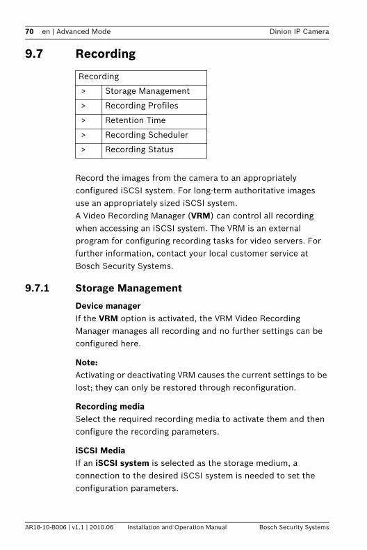
70 en | Advanced Mode Dinion IP Camera
AR18-10-B006 | v1.1 | 2010.06 Installation and Operation Manual Bosch Security Systems
9.7 Recording
Record the images from the camera to an appropriately configured iSCSI system. For long-term authoritative images use an appropriately sized iSCSI system.A Video Recording Manager (VRM) can control all recording when accessing an iSCSI system. The VRM is an external program for configuring recording tasks for video servers. For further information, contact your local customer service at Bosch Security Systems.
9.7.1 Storage Management
Device managerIf the VRM option is activated, the VRM Video Recording Manager manages all recording and no further settings can be configured here.
Note:Activating or deactivating VRM causes the current settings to be lost; they can only be restored through reconfiguration.
Recording mediaSelect the required recording media to activate them and then configure the recording parameters.
iSCSI MediaIf an iSCSI system is selected as the storage medium, a connection to the desired iSCSI system is needed to set the configuration parameters.
Recording
> Storage Management
> Recording Profiles
> Retention Time
> Recording Scheduler
> Recording Status
Dinion IP Camera Advanced Mode | en 71
Bosch Security Systems Installation and Operation Manual AR18-10-B006 | v1.1 | 2010.06
The storage system selected must be available on the network and completely set up. Amongst other things, it must have an IP address and be divided into logical drives (LUN).1. Enter the IP address of the required iSCSI destination in
the iSCSI IP address field.2. If the iSCSI destination is password protected, enter this
into the Password field.3. Click the Read button. The connection to the IP address is
established. The Storage overview field displays the logical drives.
Activating and Configuring Storage MediaThe storage overview displays the available storage media. Select individual media or iSCSI drives and transfer these to the Managed storage media list. Activate the storage media in this list and configure them for storage.
Note:Each storage medium can only be associated with one user. If a storage medium is already being used by another user, decouple the user and connect the drive to the camera. Before decoupling, make absolutely sure that the previous user no longer needs the storage medium.
1. In the Storage overview section, double-click the required storage medium, an iSCSI LUN or one of the other available drives. The medium is then added to the Managed storage media list. Newly added media is indicated in the Status column by the status Not active.
2. Click Set to activate all media in the Managed storage media list. These are indicated in the Status column by the status Online.
3. Check the box in the Rec. 1 or Rec. 2 column to specify which data stream should be recorded on the storage media selected. Rec. 1 stores stream 1, Rec. 2 stores stream 2.
4. Check the boxes for the Overwrite older recordings option to specify which older recordings can be

72 en | Advanced Mode Dinion IP Camera
AR18-10-B006 | v1.1 | 2010.06 Installation and Operation Manual Bosch Security Systems
overwritten once the available memory capacity has been used. Recording 1 corresponds to stream 1, Recording 2 corresponds to stream 2.
Note:If older recordings are not allowed to be overwritten when the available memory capacity has been used, the recording in question is stopped. Specify limitations for overwriting old recordings by configuring the retention time.
Formatting Storage MediaDelete all recordings on a storage medium at any time. Check the recordings before deleting and back up important sequences on the computer's hard drive.1. Click a storage medium in the Managed storage media list
to select it.2. Click Edit below the list. A new window opens.3. Click Formatting to delete all recordings in the storage
medium.4. Click OK to close the window.
Deactivating Storage MediaDeactivate any storage medium from the Managed storage media list. It is then no longer used for recordings.1. Click a storage medium in the Managed storage media list
to select it.2. Click Remove below the list. The storage medium is
deactivated and removed from the list.
Dinion IP Camera Advanced Mode | en 73
Bosch Security Systems Installation and Operation Manual AR18-10-B006 | v1.1 | 2010.06
9.7.2 Recording ProfilesDefine up to ten different recording profiles here, then assign these to individual days or times of day on the Recording Scheduler page. Modify the names of the recording profiles on the tabs in the Recording Scheduler page.1. Click a tab to edit the corresponding profile.2. If necessary, click Default to return all settings to their
defaults.3. Click Copy Settings to copy the currently visible settings
to other profiles. A window opens to select the target profiles for the copied settings.
4. For each profile, click Set to save.
Stream profile settingsSelect the profile setting that is to be used for each data stream when recording. This selection is independent of the selection for live data stream transmission. (The properties of the profiles are defined on the Encoder Profile page.)
Recording includesSpecify whether, in addition to video data, audio or metadata (for example alarms or VCA data) should also be recorded. Including metadata could make subsequent searches of recordings easier but it requires additional memory capacity. Without metadata, it is not possible to include video content analysis in recordings.
Standard recordingSelect the mode for standard recordings:– Continuous: the recording proceeds continuously. If the
maximum memory capacity is reached, older recordings will automatically be overwritten.
– Pre-alarm: recording takes place in the pre-alarm time, during the alarm and during the post-alarm time only.
– Off: no automatic recording takes place.
74 en | Advanced Mode Dinion IP Camera
AR18-10-B006 | v1.1 | 2010.06 Installation and Operation Manual Bosch Security Systems
StreamSelect the data stream to be used for standard recordings. (You can select the data stream for alarm recordings separately and independently of this setting.)
Alarm recordingSelect the Pre-alarm time from the list box.Select the Post-alarm time from the list box.Select the Alarm stream to use for alarm recording. The encoding interval for alarm recording can be selected from the predefined profiles.
Alarm triggersSelect the alarm type (Alarm input/ Motion/Audio alarm / Video loss alarm) that is to trigger a recording. Select the Virtual alarm sensors that are to trigger a recording, via RCP+ commands or alarm scripts, for example.
9.7.3 Retention TimeSpecify the retention times for recordings. If the available memory capacity of a medium has been used, older recordings are only overwritten if the retention time entered here has expired.Make sure that the retention time corresponds with the available memory capacity. A rule of thumb for the memory requirement is as follows: 1 GB per hour retention time with 4CIF for complete frame rate and high image quality.Enter the required retention time in hours or days for each recording. Recording 1 corresponds to Stream 1, Recording 2 corresponds to Stream 2.
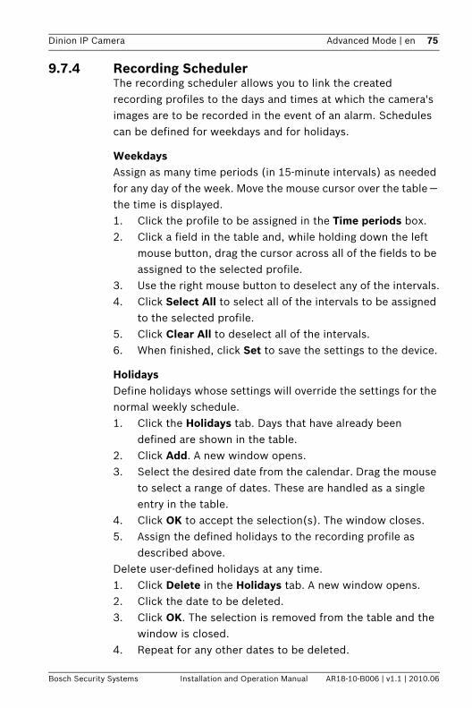
Dinion IP Camera Advanced Mode | en 75
Bosch Security Systems Installation and Operation Manual AR18-10-B006 | v1.1 | 2010.06
9.7.4 Recording SchedulerThe recording scheduler allows you to link the created recording profiles to the days and times at which the camera's images are to be recorded in the event of an alarm. Schedules can be defined for weekdays and for holidays.
WeekdaysAssign as many time periods (in 15-minute intervals) as needed for any day of the week. Move the mouse cursor over the table — the time is displayed. 1. Click the profile to be assigned in the Time periods box.2. Click a field in the table and, while holding down the left
mouse button, drag the cursor across all of the fields to be assigned to the selected profile.
3. Use the right mouse button to deselect any of the intervals.4. Click Select All to select all of the intervals to be assigned
to the selected profile.5. Click Clear All to deselect all of the intervals.6. When finished, click Set to save the settings to the device.
HolidaysDefine holidays whose settings will override the settings for the normal weekly schedule.1. Click the Holidays tab. Days that have already been
defined are shown in the table.2. Click Add. A new window opens.3. Select the desired date from the calendar. Drag the mouse
to select a range of dates. These are handled as a single entry in the table.
4. Click OK to accept the selection(s). The window closes.5. Assign the defined holidays to the recording profile as
described above.Delete user-defined holidays at any time.1. Click Delete in the Holidays tab. A new window opens.2. Click the date to be deleted.3. Click OK. The selection is removed from the table and the
window is closed.4. Repeat for any other dates to be deleted.
76 en | Advanced Mode Dinion IP Camera
AR18-10-B006 | v1.1 | 2010.06 Installation and Operation Manual Bosch Security Systems
Profile namesChange the names of the recording profiles listed in the Time periods box.1. Click a profile.2. Click Rename.3. Enter the new name and click Rename again.
Activate recordingAfter completing configuration, activate the recording schedule and start recording. Once activated, the Recording Profiles and the Recording Scheduler are deactivated and the configuration cannot be modified. Terminate recording at any time to modify the configuration.1. Click Start to activate the recording schedule.2. Click Stop to deactivate the recording schedule.
Recordings that are currently running are interrupted and the configuration can be modified.
Recording statusThe graphic indicates the recording activity. An animated graphic is seen when recording is taking place.
9.7.5 Recording StatusDetails of the recording status are displayed here for information. These settings cannot be changed.
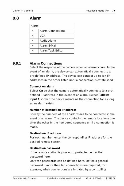
Dinion IP Camera Advanced Mode | en 77
Bosch Security Systems Installation and Operation Manual AR18-10-B006 | v1.1 | 2010.06
9.8 Alarm
9.8.1 Alarm ConnectionsSelect the response of the camera when an alarm occurs. In the event of an alarm, the device can automatically connect to a pre-defined IP address. The device can contact up to ten IP addresses in the order listed until a connection is established.
Connect on alarmSelect On so that the camera automatically connects to a pre-defined IP address in the event of an alarm. Select Follows input 1 so that the device maintains the connection for as long as an alarm exists.
Number of destination IP addressSpecify the numbers of the IP addresses to be contacted in the event of an alarm. The device contacts the remote locations one after the other in the numbered sequence until a connection is made.
Destination IP addressFor each number, enter the corresponding IP address for the desired remote station.
Destination passwordIf the remote station is password protected, enter the password here.Only ten passwords can be defined here. Define a general password if more than ten connections are required, for example, when connections are initiated by a controlling
Alarm
> Alarm Connections
> VCA
> Audio Alarm
> Alarm E-Mail
> Alarm Task Editor
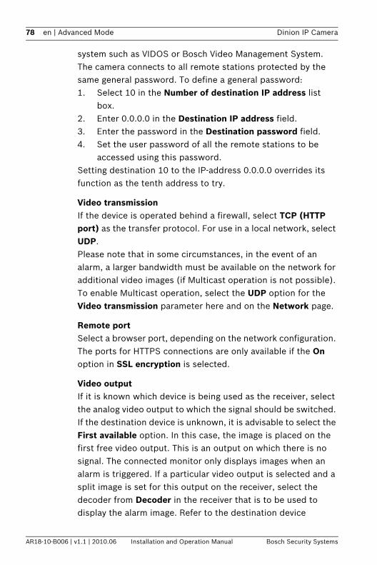
78 en | Advanced Mode Dinion IP Camera
AR18-10-B006 | v1.1 | 2010.06 Installation and Operation Manual Bosch Security Systems
system such as VIDOS or Bosch Video Management System. The camera connects to all remote stations protected by the same general password. To define a general password:1. Select 10 in the Number of destination IP address list
box.2. Enter 0.0.0.0 in the Destination IP address field.3. Enter the password in the Destination password field.4. Set the user password of all the remote stations to be
accessed using this password.Setting destination 10 to the IP-address 0.0.0.0 overrides its function as the tenth address to try.
Video transmissionIf the device is operated behind a firewall, select TCP (HTTP port) as the transfer protocol. For use in a local network, select UDP.Please note that in some circumstances, in the event of an alarm, a larger bandwidth must be available on the network for additional video images (if Multicast operation is not possible). To enable Multicast operation, select the UDP option for the Video transmission parameter here and on the Network page.
Remote portSelect a browser port, depending on the network configuration. The ports for HTTPS connections are only available if the On option in SSL encryption is selected.
Video outputIf it is known which device is being used as the receiver, select the analog video output to which the signal should be switched. If the destination device is unknown, it is advisable to select the First available option. In this case, the image is placed on the first free video output. This is an output on which there is no signal. The connected monitor only displays images when an alarm is triggered. If a particular video output is selected and a split image is set for this output on the receiver, select the decoder from Decoder in the receiver that is to be used to display the alarm image. Refer to the destination device
Dinion IP Camera Advanced Mode | en 79
Bosch Security Systems Installation and Operation Manual AR18-10-B006 | v1.1 | 2010.06
documentation concerning image display options and available video outputs.
DecoderSelect a decoder of the receiver to display the alarm image. The decoder selected has an impact on the position of the image in a split screen.
SSL encryptionSSL encryption protects data used for establishing a connection, such as the password. By selecting On, only encrypted ports are available for the Remote port parameter. SSL encryption must be activated and configured on both sides of a connection. The appropriate certificates must also have been uploaded. Configure and activate encryption for media data (video, metadata) on the Encryption page.
Auto-connectSelect On to automatically re-established a connection to one of the previously specified IP addresses after each reboot, connection breakdown, or network failure.
AudioSelect On to transmit the audio stream with an alarm connection.

80 en | Advanced Mode Dinion IP Camera
AR18-10-B006 | v1.1 | 2010.06 Installation and Operation Manual Bosch Security Systems
9.8.2 Video Content Analyses (VCA)The camera has integrated VCA which can detect and analyze changes in the signal using image processing algorithms. Such changes can be due to movements in the camera's field of view. Select various VCA configurations and adapt these to your application, as required. The Silent MOTION+ configuration is active by default. In this configuration, metadata is created to facilitate searches of recordings, however, no alarm is triggered. 1. Select a VCA configuration and make the required settings.2. If necessary, click the Default button to return all settings
to their default values.
Note:If there is not enough computing power, priority is given to live images and recordings. This can lead to impairment of the VCA system. Observe the processor load and optimize the encoder settings or the VCA settings if necessary, or turn off VCA completely.
Dinion IP Camera Advanced Mode | en 81
Bosch Security Systems Installation and Operation Manual AR18-10-B006 | v1.1 | 2010.06
9.8.3 VCA configuration- ProfilesConfigure two profiles with different VCA configurations. Save profiles on your computer's hard drive and load saved profiles from there. This can be useful if testing a number of different configurations. Save a functioning configuration and test new settings. Use the saved configuration to restore the original settings at any time.1. Select a VCA profile and enter the required settings.2. If necessary, click Default to return all settings to default
values.3. Click the Save... to save the profile settings to another file.
A new window opens in which to specify the file name and where to save it.
4. Click Load... to load a saved profile. A new window opens in which to select the profile file and specify where to save the file.
To rename a profile:1. To rename the file, click the icon to the right of the list field
and enter the new profile name in the field.2. Click the icon again. The new profile name is saved.
The current alarm status is displayed for information purposes.
Aggregation time (s)Set an aggregation time of between 0 and 20 seconds. The aggregation time always starts when an alarm event occurs. It extends the alarm event by the value set. This prevents alarm events that occur in quick succession from triggering several alarms and successive events in a rapid sequence. No further alarm is triggered during the aggregation time.The post-alarm time set for alarm recordings only starts once the aggregation time has expired.
Analysis typeSelect the required analysis algorithm. By default, only Motion+ is available — this offers a motion detector and essential recognition of tampering.

82 en | Advanced Mode Dinion IP Camera
AR18-10-B006 | v1.1 | 2010.06 Installation and Operation Manual Bosch Security Systems
Metadata is always created for a video content analysis, unless this was explicitly excluded. Depending on the analysis type selected and the relevant configuration, additional information overlays the video image in the preview window next to the parameter settings. With the Motion+ analysis type, for example, the sensor fields in which motion is recorded are marked with rectangles.
Note:Additional analysis algorithms with comprehensive functions, such as IVMD and IVA, are available from Bosch Security Systems.
Motion detectorMotion detection is available for the Motion+ analysis type. For the detector to function, the following conditions must be met:– Analysis must be activated.– At least one sensor field must be activated.– The individual parameters must be configured to suit the
operating environment and the desired responses.– The sensitivity must be set to a value greater than zero.
Note:Reflections of light (from glass surfaces, etc.), lights switching on and off, or changes in the light level caused by cloud movement on a sunny day can trigger unintended responses from the motion detector and generate false alarms. Run a series of tests at different times of the day and night to ensure that the video sensor is operating as intended. For indoor surveillance, ensure constant lighting of the areas during the day and at night.
SensitivitySensitivity is available for the Motion+ analysis type. The basic sensitivity of the motion detector can be adjusted for the environmental conditions to which the camera is subject. The sensor reacts to variations in the brightness of the video image. The darker the observation area, the higher the value that must be selected.
Dinion IP Camera Advanced Mode | en 83
Bosch Security Systems Installation and Operation Manual AR18-10-B006 | v1.1 | 2010.06
Minimum object sizeSpecify the number of sensor fields that a moving object must cover to generate an alarm. This setting prevents objects that are too small from triggering an alarm. A minimum value of 4 is recommended. This value corresponds to four sensor fields.
Debounce time 1 sThe debounce time prevents very brief alarm events from triggering individual alarms. If the Debounce time 1 s option is activated, an alarm event must last at least 1 second to trigger an alarm.
Selecting the areaSelect the areas of the image to be monitored by the motion detector. The video image is subdivided into square sensor fields. Activate or deactivate each of these fields individually. To exclude particular regions of the camera's field of view from monitoring due to continuous movement (by a tree in the wind, for example), the relevant fields can be deactivated.1. Click Select Area to configure the sensor fields. A new
window opens.2. If necessary, click Clear All first to clear the current
selection (fields marked red).3. Left-click the fields to be activated. Activated fields are
marked red.4. If necessary, click Select All to select the entire video-
frame for monitoring.5. Right-click any fields to deactivate.6. Click OK to save the configuration.7. Click the close button (X) in the window title bar to close
the window without saving the changes.
Tamper detectionDetect tampering of cameras and video cables by means of various options. Run a series of tests at different times of the day and night to ensure that the video sensor is operating as intended.
84 en | Advanced Mode Dinion IP Camera
AR18-10-B006 | v1.1 | 2010.06 Installation and Operation Manual Bosch Security Systems
Sensitivity and Trigger delay (s) can only be changed if Reference check is selected.
SensitivityThe basic sensitivity of the tamper detection can be adjusted for the environmental conditions to which the camera is subject. The algorithm reacts to the differences between the reference image and the current video image. The darker the observation area, the higher the value that must be selected.
Trigger delay (s)Set delayed alarm triggering here. The alarm is only triggered after a set time interval in seconds has elapsed and then only if the triggering condition still exists. If the original condition has been restored before this time interval elapses, the alarm is not triggered. This avoids false alarms triggered by short-term changes, for example, cleaning activities in the direct field of vision of the camera.
Global change (slider)Set how large the global change in the video image must be for an alarm to be triggered. This setting is independent of the sensor fields selected under Select Area. Set a high value if fewer sensor fields need to change to trigger an alarm. With a low value, it is necessary for changes to occur simultaneously in a large number of sensor fields to trigger an alarm. This option allows detection, independently of motion alarms, manipulation of the orientation or location of a camera resulting from turning the camera mount bracket, for example.
Global changeActivate this function if the global change, as set with the Global change slide control, should trigger an alarm.
Scene too brightActivate this function if tampering associated with exposure to extreme light (for instance, shining a flashlight directly on the objective) should trigger an alarm. The average brightness of the scene provides a basis for recognition.
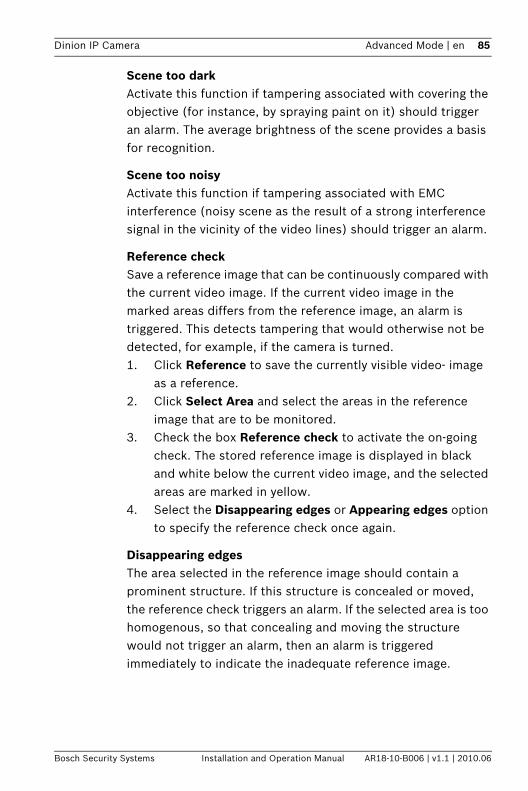
Dinion IP Camera Advanced Mode | en 85
Bosch Security Systems Installation and Operation Manual AR18-10-B006 | v1.1 | 2010.06
Scene too darkActivate this function if tampering associated with covering the objective (for instance, by spraying paint on it) should trigger an alarm. The average brightness of the scene provides a basis for recognition.
Scene too noisyActivate this function if tampering associated with EMC interference (noisy scene as the result of a strong interference signal in the vicinity of the video lines) should trigger an alarm.
Reference checkSave a reference image that can be continuously compared with the current video image. If the current video image in the marked areas differs from the reference image, an alarm is triggered. This detects tampering that would otherwise not be detected, for example, if the camera is turned.1. Click Reference to save the currently visible video- image
as a reference.2. Click Select Area and select the areas in the reference
image that are to be monitored.3. Check the box Reference check to activate the on-going
check. The stored reference image is displayed in black and white below the current video image, and the selected areas are marked in yellow.
4. Select the Disappearing edges or Appearing edges option to specify the reference check once again.
Disappearing edgesThe area selected in the reference image should contain a prominent structure. If this structure is concealed or moved, the reference check triggers an alarm. If the selected area is too homogenous, so that concealing and moving the structure would not trigger an alarm, then an alarm is triggered immediately to indicate the inadequate reference image.
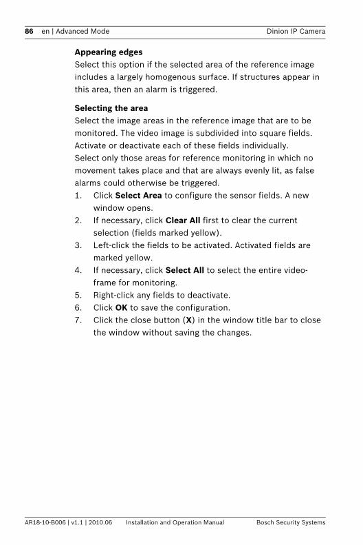
86 en | Advanced Mode Dinion IP Camera
AR18-10-B006 | v1.1 | 2010.06 Installation and Operation Manual Bosch Security Systems
Appearing edgesSelect this option if the selected area of the reference image includes a largely homogenous surface. If structures appear in this area, then an alarm is triggered.
Selecting the areaSelect the image areas in the reference image that are to be monitored. The video image is subdivided into square fields. Activate or deactivate each of these fields individually.Select only those areas for reference monitoring in which no movement takes place and that are always evenly lit, as false alarms could otherwise be triggered.1. Click Select Area to configure the sensor fields. A new
window opens.2. If necessary, click Clear All first to clear the current
selection (fields marked yellow).3. Left-click the fields to be activated. Activated fields are
marked yellow.4. If necessary, click Select All to select the entire video-
frame for monitoring.5. Right-click any fields to deactivate.6. Click OK to save the configuration.7. Click the close button (X) in the window title bar to close
the window without saving the changes.
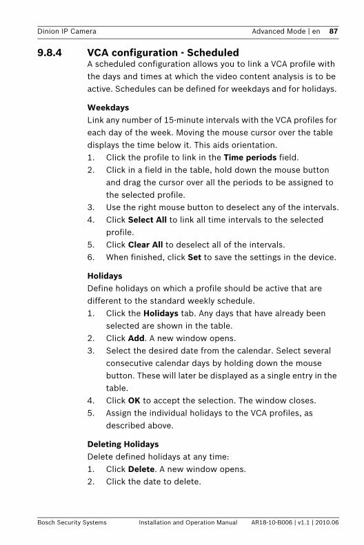
Dinion IP Camera Advanced Mode | en 87
Bosch Security Systems Installation and Operation Manual AR18-10-B006 | v1.1 | 2010.06
9.8.4 VCA configuration - ScheduledA scheduled configuration allows you to link a VCA profile with the days and times at which the video content analysis is to be active. Schedules can be defined for weekdays and for holidays.
WeekdaysLink any number of 15-minute intervals with the VCA profiles for each day of the week. Moving the mouse cursor over the table displays the time below it. This aids orientation.1. Click the profile to link in the Time periods field.2. Click in a field in the table, hold down the mouse button
and drag the cursor over all the periods to be assigned to the selected profile.
3. Use the right mouse button to deselect any of the intervals.4. Click Select All to link all time intervals to the selected
profile.5. Click Clear All to deselect all of the intervals.6. When finished, click Set to save the settings in the device.
HolidaysDefine holidays on which a profile should be active that are different to the standard weekly schedule.1. Click the Holidays tab. Any days that have already been
selected are shown in the table.2. Click Add. A new window opens.3. Select the desired date from the calendar. Select several
consecutive calendar days by holding down the mouse button. These will later be displayed as a single entry in the table.
4. Click OK to accept the selection. The window closes.5. Assign the individual holidays to the VCA profiles, as
described above.
Deleting HolidaysDelete defined holidays at any time:1. Click Delete. A new window opens.2. Click the date to delete.
88 en | Advanced Mode Dinion IP Camera
AR18-10-B006 | v1.1 | 2010.06 Installation and Operation Manual Bosch Security Systems
3. Click OK. The item is deleted from the table and the window closes.
4. The process must be repeated for deleting additional days.
Dinion IP Camera Advanced Mode | en 89
Bosch Security Systems Installation and Operation Manual AR18-10-B006 | v1.1 | 2010.06
9.8.5 VCA configuration - Event triggeredThis configuration allows you to stipulate that the video content analysis is only to be activated when triggered by an event. As long as no trigger is activated, the Silent MOTION+ configuration in which metadata is created is active; this metadata facilitates searches of recordings, but does not trigger an alarm.
TriggerSelect a physical alarm or a virtual alarm as a trigger. A virtual alarm is created using software, with RCP+ commands or alarm scripts, for example.
Trigger activeSelect the VCA configuration here that is to be enabled via an active trigger. A green check mark to the right of the list field indicates that the trigger is active.
Trigger inactiveSelect the VCA configuration here that is to be activated if the trigger is not active. A green check mark to the right of the list field indicates that the trigger is inactive.
Delay (s)Select the delay period for the reaction of the video content analysis to trigger signals. The alarm is only triggered after a set time interval in seconds has elapsed and then only if the triggering condition still exists. If the original condition has been restored before this time interval elapses, the alarm is not triggered. A delay period may be useful in avoiding false alarms or frequent triggering. During the delay period, the Silent MOTION+ configuration is always enabled.
90 en | Advanced Mode Dinion IP Camera
AR18-10-B006 | v1.1 | 2010.06 Installation and Operation Manual Bosch Security Systems
9.8.6 Audio AlarmCreate alarms based on audio signals. Configure signal strengths and frequency ranges so that false alarms, for example, machine noise or background noise, are avoided.Set up normal audio transmission before configuring the audio alarm.
Audio alarmSelect On for the device to generate audio alarms.
NameThe name makes it easier to identify the alarm in extensive video monitoring systems, for example with the VIDOS and Bosch Video Management System programs. Enter a unique and clear name here.
Signal RangesExclude particular signal ranges in order to avoid false alarms. For this reason the total signal is divided into 13 tonal ranges (mel scale). Check or uncheck the boxes below the graphic to include or exclude individual ranges.
ThresholdSet up the threshold on the basis of the signal visible in the graphic Set the threshold using the slide control or, alternatively, move the white line directly in the graphic using the mouse.
SensitivityUse this setting to adapt the sensitivity to the sound environment and effectively suppress individual signal peaks. A high value represents a high level of sensitivity.
Dinion IP Camera Advanced Mode | en 91
Bosch Security Systems Installation and Operation Manual AR18-10-B006 | v1.1 | 2010.06
9.8.7 Alarm E-MailAs an alternative to automatic connecting, alarm states can also be documented by e-mail. This makes it possible to notify a recipient who does not have a video receiver. In this case, the camera automatically sends an e-mail to a user-defined e-mail address.
Send alarm e-mailSelect On for the device to automatically send an alarm e-mail in the event of an alarm.
Mail server IP addressEnter the IP address of a mail server that operates on the SMTP standard (Simple Mail Transfer Protocol). Outgoing e-mails are sent to the mail server via the address entered. Otherwise, leave the box blank (0.0.0.0).
SMTP user nameEnter a registered user name for the chosen mail server.
SMTP passwordEnter the required password for the registered user name.
FormatSelect the data format of the alarm message.– Standard (with JPEG): e-mail with JPEG image file
attachment.– SMS: e-mail in SMS format to an e-mail-to-SMS gateway
(for example, to send an alarm by cellphone) without an image attachment.
When a cellphone is used as the receiver, make sure to activate the e-mail or SMS function, depending on the format, so that these messages can be received. Obtain information on operating your cellphone from your cellphone provider.
Attach JPEG from cameraCheck the box to specify that JPEG images are sent from the camera.
92 en | Advanced Mode Dinion IP Camera
AR18-10-B006 | v1.1 | 2010.06 Installation and Operation Manual Bosch Security Systems
Destination addressEnter the e-mail address for alarm e-mails here. The maximum address length is 49 characters.
Sender nameEnter a unique name for the e-mail sender, for example, the location of the device. This makes it easier to identify the origin of the e-mail.
Test e-mailClick Send Now to test the e-mail function. An alarm e-mail is immediately created and sent.
Dinion IP Camera Advanced Mode | en 93
Bosch Security Systems Installation and Operation Manual AR18-10-B006 | v1.1 | 2010.06
9.8.8 Alarm Task EditorEditing scripts on this page overwrites all settings and entries on the other alarm pages. This procedure cannot be reversed.To edit this page, you should have programming knowledge and be familiar with the information in the Alarm Task Script Language document and the English language. The document can be found on the product DVD supplied.
As an alternative to the alarm settings on the various alarm pages, enter the desired alarm functions in script form here. This will overwrite all settings and entries on the other alarm pages.1. Click Examples under the Alarm Task Editor field to see
some script examples. A new window opens.2. Enter new scripts in the Alarm Task Editor field or change
existing scripts in line with your requirements.3. When finished, click Set to transmit the scripts to the
device. If the transfer was successful, the message Script successfully parsed. is displayed over the text field. If it was not successful, an error message is displayed with further information.
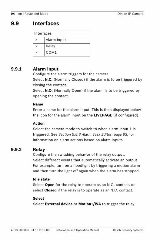
94 en | Advanced Mode Dinion IP Camera
AR18-10-B006 | v1.1 | 2010.06 Installation and Operation Manual Bosch Security Systems
9.9 Interfaces
9.9.1 Alarm inputConfigure the alarm triggers for the camera.Select N.C. (Normally Closed) if the alarm is to be triggered by closing the contact.Select N.O. (Normally Open) if the alarm is to be triggered by opening the contact.
NameEnter a name for the alarm input. This is then displayed below the icon for the alarm input on the LIVEPAGE (if configured).
ActionSelect the camera mode to switch to when alarm input 1 is triggered. See Section 9.8.8 Alarm Task Editor, page 93, for information on alarm actions based on alarm inputs.
9.9.2 RelayConfigure the switching behavior of the relay output. Select different events that automatically activate an output. For example, turn on a floodlight by triggering a motion alarm and then turn the light off again when the alarm has stopped.
Idle stateSelect Open for the relay to operate as an N.O. contact, or select Closed if the relay is to operate as an N.C. contact.
SelectSelect External device or Motion+/IVA to trigger the relay.
Interfaces
> Alarm input
> Relay
> COM1
Dinion IP Camera Advanced Mode | en 95
Bosch Security Systems Installation and Operation Manual AR18-10-B006 | v1.1 | 2010.06
Relay nameThe relay can be assigned a name here. The name is shown on the button next to Trigger relay. The LIVEPAGE can also be configured to display the name next to the relay icon.
Trigger relayClick the button to switch the relay manually (for example, for testing purposes or to operate a door opener).
9.9.3 COM1Configure the data connector for the camera.
Serial port functionSelect a controllable unit from the list. If you wish to use the serial port to transmit transparent data, select Transparent. Select Terminal if you wish to operate the unit from a terminal.After selecting a unit, the remaining parameters in the window are set automatically and should not be changed.
Camera IDIf necessary, enter the ID of the peripheral you wish to control (for example a dome camera or pan/tilt head).
Baud rateSelect the value for the transmission rate in bps.
Data bitsThe number of data bits per character cannot be changed.
Stop bitsSelect the number of stop bits per character.
Parity checkSelect the type of parity check.
Interface modeSelect the desired protocol for the serial interface.
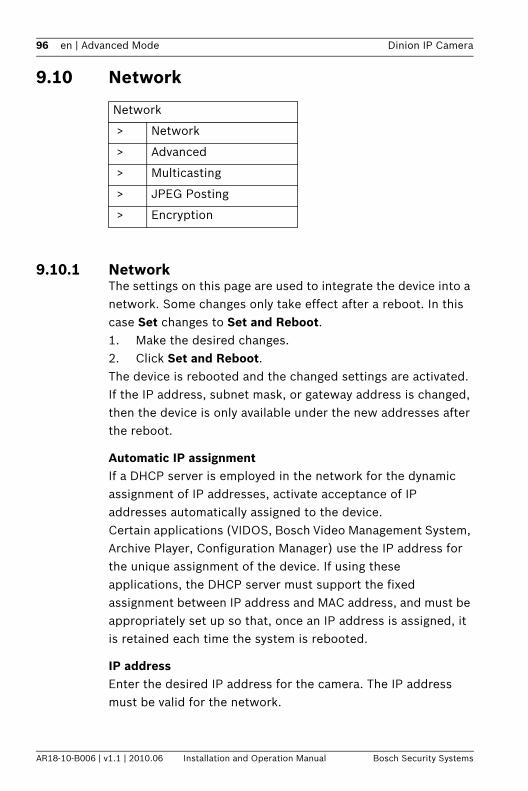
96 en | Advanced Mode Dinion IP Camera
AR18-10-B006 | v1.1 | 2010.06 Installation and Operation Manual Bosch Security Systems
9.10 Network
9.10.1 NetworkThe settings on this page are used to integrate the device into a network. Some changes only take effect after a reboot. In this case Set changes to Set and Reboot.1. Make the desired changes.2. Click Set and Reboot.The device is rebooted and the changed settings are activated. If the IP address, subnet mask, or gateway address is changed, then the device is only available under the new addresses after the reboot.
Automatic IP assignmentIf a DHCP server is employed in the network for the dynamic assignment of IP addresses, activate acceptance of IP addresses automatically assigned to the device.Certain applications (VIDOS, Bosch Video Management System, Archive Player, Configuration Manager) use the IP address for the unique assignment of the device. If using these applications, the DHCP server must support the fixed assignment between IP address and MAC address, and must be appropriately set up so that, once an IP address is assigned, it is retained each time the system is rebooted.
IP addressEnter the desired IP address for the camera. The IP address must be valid for the network.
Network
> Network
> Advanced
> Multicasting
> JPEG Posting
> Encryption
Dinion IP Camera Advanced Mode | en 97
Bosch Security Systems Installation and Operation Manual AR18-10-B006 | v1.1 | 2010.06
Subnet maskEnter the appropriate subnet mask for the set IP address.
Gateway addressFor the device to establish a connection to a remote location in a different subnet, enter the IP address of the gateway here. Otherwise, this field can remain empty (0.0.0.0).
DNS server addressThe device is easier to access if it is listed on a DNS server. For example, to establish an Internet connection to the camera, it is sufficient to enter the name given to the device on the DNS server as a URL in the browser. Enter the DNS server's IP address. Servers are supported for secure and dynamic DNS.
Details >>
Video transmissionIf the device is used behind a firewall, TCP (Port 80) should be selected as the transmission protocol. For use in a local network, choose UDP.Multicast operation is only possible with the UDP protocol. The TCP protocol does not support multicast connections. The MTU value in UDP mode is 1514 bytes.
HTTP browser portSelect a different HTTP browser port from the list if required. The default HTTP port is 80. To limit connection to HTTPS, deactivate the HTTP port. To do this, activate the Off option.
HTTPS browser portTo limit browser access to encrypted connections, choose an HTTPS port from the list. The standard HTTPS port is 443. Select the Off option to deactivate HTTPS ports and limit connections to unencrypted ports.The camera uses the TLS 1.0 protocol. Ensure that the browser has been configured to support this protocol. Also ensure that Java application support is activated (in the Java Plug-in Control Panel of the Windows Control Panel).
98 en | Advanced Mode Dinion IP Camera
AR18-10-B006 | v1.1 | 2010.06 Installation and Operation Manual Bosch Security Systems
To limit connections to SSL encryption, set the Off option in the HTTP browser port, the RCP+ port, and Telnet support. This deactivates all unencrypted connections allowing connections on the HTTPS port only.Configure and activate encryption for media data (video, audio, metadata) on the Encryption page.
RCP+ port 1756Activating RCP+ port 1756 allows unencrypted connections on this port. To allow only encrypted connections, set the Off option to deactivate the port.
Telnet supportActivating Telenet support allows unencrypted connections on this port. To allow only encrypted connections, set the Off option to deactivate telnet support, making telnet connections impossible.
Interface mode ETHIf necessary, select the Ethernet link type for interface ETH. Depending on the device connected, it may be necessary to select a special operation type.
Network MSS (Byte)Set the maximum segment size for the IP packet's user data here. This gives the option to adjust the size of the data packets to the network environment and to optimize data transmission. Please comply with the MTU value of 1,514 bytes in UDP mode.
iSCSI MSS (Byte)Specify a higher MSS value for a connection to the iSCSI system than for the other data traffic via the network. The potential value depends on the network structure. A higher value is only useful if the iSCSI system is located in the same subnet as the camera.
Dinion IP Camera Advanced Mode | en 99
Bosch Security Systems Installation and Operation Manual AR18-10-B006 | v1.1 | 2010.06
Enable DynDNSDynDNS.org is a DNS hosting service that stores IP addresses in a database ready for use. It allows selecting the device via the Internet using a host name, without having to know the current IP address of the device. Enable this service here. To do this, obtain an account with DynDNS.org and register the required host name for the device on that site.
Note:Information about the service, registration process and available host names can be found at DynDNS.org.
Host nameEnter the host name registered on DynDNS.org for the device here.
User nameEnter the user name registered at DynDNS.org here.
PasswordEnter the password registered at DynDNS.org here.
Force registration nowForce the registration by transferring the IP address to the DynDNS server. Entries that change frequently are not provided in the Domain Name System. It is a good idea to force the registration when setting up the device for the first time. Only use this function when necessary and no more than once a day, to avoid the possibility of being blocked by the service provider. To transfer the IP address of the device, click the Register button.
StatusThe status of the DynDNS function is displayed here for information purposes; these settings cannot be changed.
100 en | Advanced Mode Dinion IP Camera
AR18-10-B006 | v1.1 | 2010.06 Installation and Operation Manual Bosch Security Systems
9.10.2 AdvancedThe settings on this page are used to set advanced settings the network. Some changes only take effect after a reboot. In this case Set changes to Set and Reboot.1. Make the desired changes.2. Click Set and Reboot.The device is rebooted and the changed settings are activated.
SNMPThe camera supports the SNMP V2 (Simple Network Management Protocol) for managing and monitoring network components, and can send SNMP messages (traps) to IP addresses. It supports SNMP MIB II in the unified code.If On is selected for the SNMP parameter and a SNMP host address is not entered, the device does not send the traps automatically and will only reply to SNMP requests. If one or two SNMP host addresses are entered, SNMP traps are sent automatically. Select Off to deactivate the SNMP function.
1. SNMP host address / 2. SNMP host addressTo send SNMP traps automatically, enter the IP addresses of one or two target devices here.
SNMP trapsTo choose which traps are sent:1. Click Select. A dialog box appears.2. Click the check boxes of the appropriate traps.3. Click Set to close the window and send all of the checked
traps.
Authentication (802.1x)To configure Radius server authentication, connect the camera directly to a computer using a network cable. If a Radius server controls access rights over the network, select On to activate authentication to communicate with the device. 1. Enter the user name that the Radius server uses for the
camera in the Identity field.2. Enter the Password that the Radius server expects from
the camera.
Dinion IP Camera Advanced Mode | en 101
Bosch Security Systems Installation and Operation Manual AR18-10-B006 | v1.1 | 2010.06
RTSP portIf necessary, select a different port for the exchange of the RTSP data from the list. The standard RTSP port is 554. Select Off to deactivate the RTSP function.
9.10.3 MulticastingIn addition to a one-to-one connection between a camera and a single receiver (unicast), the camera can enable multiple receivers to receive the video signal simultaneously. This is either done by duplicating the data stream in the device and then distributing it to multiple receivers (multi-unicast), or by distributing an individual data stream in the network itself to multiple receivers in a defined group (multicast). Enter a dedicated multicast address and port for each stream. Then switch between the streams by clicking the associated tabs.The prerequisite for multicast operation is a multicast-capable network that uses the UDP and IGMP protocols. Other group membership protocols are not supported. The TCP protocol does not support multicast connections.A special IP address (class D address) must be configured for multicast operation in a multicast-enabled network. The network must support group IP addresses and the Internet Group Management Protocol (IGMP V2). The address range is from 225.0.0.0 to 239.255.255.255. The multicast address can be the same for multiple streams. However, it is then necessary to use a different port in each case so that multiple data streams are not sent simultaneously using the same port and multicast address. The settings must be made individually for each stream.
EnableEnable simultaneous data reception on several receivers that need to activate the multicast function. To do this, check the box and then enter the multicast address.
Multicast AddressEnter a valid multicast address to be operated in multicast mode (duplication of the data stream in the network). With the
102 en | Advanced Mode Dinion IP Camera
AR18-10-B006 | v1.1 | 2010.06 Installation and Operation Manual Bosch Security Systems
setting 0.0.0.0 the encoder for the stream operates in multi-unicast mode (copying of data stream in device). The camera supports multi-unicast connections for up to five simultaneously-connected receivers.Duplication of data places a heavy demand on the CPU and can lead to impairment of the image quality under certain circumstances.
PortEnter the port address for the stream here.
StreamingClick the checkbox to activate multicast streaming mode. An activated stream is marked with a check. (Streaming is typically not required for standard multicast operation.)
Multicast packet TTLA value can be entered to specify how long the multicast data packets are active on the network. If multicast is to be run via a router, the value must be greater than 1.
9.10.4 JPEG PostingSave individual JPEG images on an FTP server at specific intervals. If required, retrieve these images at a later date to reconstruct alarm events. JPEG resolution corresponds to the highest setting from the two data streams.
File nameSelect how file names are created for the individual images that are transmitted.– Overwrite: The same file name is always used and any
existing file will be overwritten by the current file.– Increment: A number from 000 to 255 is added to the file
name and automatically incremented by 1. When it reaches 255, it starts again from 000.
– Date/time suffix: The date and time are automatically added to the file name. When setting this parameter, ensure that the date and time of the device are always set
Dinion IP Camera Advanced Mode | en 103
Bosch Security Systems Installation and Operation Manual AR18-10-B006 | v1.1 | 2010.06
correctly . For eample, the file snap011005_114530.jpg was stored on October 1, 2005 at 11.45 and 30 seconds.
Posting intervalEnter the interval in seconds at which the images are sent to an FTP server. Enter zero for no images to be sent.
FTP server IP addressEnter the IP address of the FTP server on which to save the JPEG images.
FTP server loginEnter your login name for the FTP server.
FTP server passwordEnter the password that gives access to the FTP server.
Path on FTP serverEnter an exact path to post the images on the FTP server.
9.10.5 EncryptionIf an encryption license is installed, this submenu gives access to the encryption parameters.
104 en | Advanced Mode Dinion IP Camera
AR18-10-B006 | v1.1 | 2010.06 Installation and Operation Manual Bosch Security Systems
9.11 Service
9.11.1 Maintenance
FirmwareThe camera functions and parameters can be updated by uploading new firmware. To do this, the latest firmware package is transferred to the device via the network. The firmware is installed there automatically. Thus, a camera can be serviced and updated remotely without requiring a technician to make changes to the device on site. The latest firmware can be obtained from your customer service center or from the Bosch Security Systems download area.
To update the firmware:1. First, store the firmware file on your hard disk.2. Enter the full path for the firmware file in the field or click
Browse to locate and select the file.3. Click Upload to begin transferring the file to the device.
The progress bar allows monitoring of the transfer.
Service
> Maintenance
> Licenses
> System Overview
CAUTION! Before starting a firmware update, make sure to select the correct upload file. Uploading the wrong files can result in the device no longer being addressable, requiring it to be replaced.Do not interrupt the firmware installation. Even changing to another page or closing the browser window leads to interruption. Interruption may lead to faulty coding of the Flash memory. This can result in the device no longer being addressable, requiring it to be replaced.
Dinion IP Camera Advanced Mode | en 105
Bosch Security Systems Installation and Operation Manual AR18-10-B006 | v1.1 | 2010.06
The new firmware is unpacked and the Flash memory is reprogrammed. The time remaining is shown by the message going to reset Reconnecting in ... seconds. When the upload is completed successfully, the device reboots automatically.If the operating status LED lights up red, the upload has failed and must be repeated. To perform the upload, switch to a special page:1. In the address bar of your browser, enter /main.htm after
the device IP address, for example:192.168.0.10/main.htm
2. Repeat the upload.
ConfigurationSave configuration data for the camera to a computer and load saved configuration data from a computer to the device.To save the camera settings:1. Click Download; a dialog box appears.2. Follow the instructions to save the current settings.To load configuration data from the computer to the device:1. Enter the full path of the file to upload or click Browse to
select the desired file.2. Make certain that the file to be loaded comes from the
same device type as the device to be reconfigured.3. Click Upload to begin transmission to the device. The
progress bar allows monitoring of the transfer.Once the upload is complete, the new configuration is activated. The time remaining is shown by the message going to reset Reconnecting in ... seconds. When the upload is completed successfully, the device reboots automatically.
SSL certificateTo work with an SSL connection, both sides of the connection must have the appropriate certificates. Upload one or more certificate files, one at a time, to the camera. 1. Enter the full path of the file to upload or click Browse to
locate the file.2. Click Upload to start the file transfer.
106 en | Advanced Mode Dinion IP Camera
AR18-10-B006 | v1.1 | 2010.06 Installation and Operation Manual Bosch Security Systems
Once all files have been successfully uploaded, the device must be rebooted. In the address field of the browser, enter /reset after the camera's IP address, for example:192.168.0.10/resetThe new SSL certificate is valid.
Maintenance logDownload an internal maintenance log from the device to send it to Customer Service for support purposes. Click Download and select a storage location for the file.
9.11.2 LicensesThis window is for the activation of additional functions by entering activation codes. An overview of installed licenses is shown.
9.11.3 System OverviewThis window is for information only and cannot be modified. Keep this information at hand when seeking technical support.Select the text on this page with a mouse and copy it so that it can be pasted into an e-mail if required.
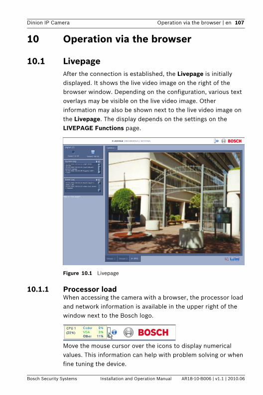
Dinion IP Camera Operation via the browser | en 107
Bosch Security Systems Installation and Operation Manual AR18-10-B006 | v1.1 | 2010.06
10 Operation via the browser
10.1 LivepageAfter the connection is established, the Livepage is initially displayed. It shows the live video image on the right of the browser window. Depending on the configuration, various text overlays may be visible on the live video image. Other information may also be shown next to the live video image on the Livepage. The display depends on the settings on the LIVEPAGE Functions page.
Figure 10.1 Livepage
10.1.1 Processor load When accessing the camera with a browser, the processor load and network information is available in the upper right of the window next to the Bosch logo.
Move the mouse cursor over the icons to display numerical values. This information can help with problem solving or when fine tuning the device.
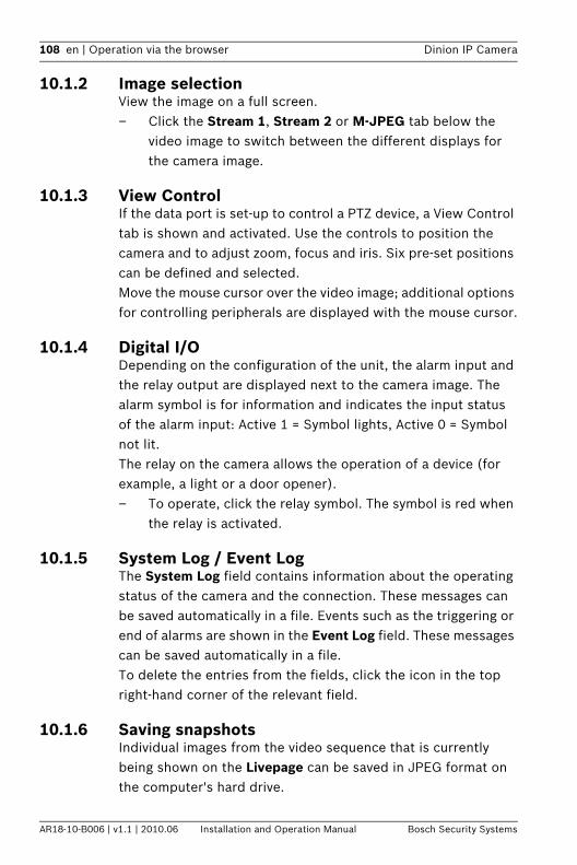
108 en | Operation via the browser Dinion IP Camera
AR18-10-B006 | v1.1 | 2010.06 Installation and Operation Manual Bosch Security Systems
10.1.2 Image selectionView the image on a full screen.– Click the Stream 1, Stream 2 or M-JPEG tab below the
video image to switch between the different displays for the camera image.
10.1.3 View ControlIf the data port is set-up to control a PTZ device, a View Control tab is shown and activated. Use the controls to position the camera and to adjust zoom, focus and iris. Six pre-set positions can be defined and selected. Move the mouse cursor over the video image; additional options for controlling peripherals are displayed with the mouse cursor.
10.1.4 Digital I/ODepending on the configuration of the unit, the alarm input and the relay output are displayed next to the camera image. The alarm symbol is for information and indicates the input status of the alarm input: Active 1 = Symbol lights, Active 0 = Symbol not lit. The relay on the camera allows the operation of a device (for example, a light or a door opener).– To operate, click the relay symbol. The symbol is red when
the relay is activated.
10.1.5 System Log / Event LogThe System Log field contains information about the operating status of the camera and the connection. These messages can be saved automatically in a file. Events such as the triggering or end of alarms are shown in the Event Log field. These messages can be saved automatically in a file.To delete the entries from the fields, click the icon in the top right-hand corner of the relevant field.
10.1.6 Saving snapshotsIndividual images from the video sequence that is currently being shown on the Livepage can be saved in JPEG format on the computer's hard drive.

Dinion IP Camera Operation via the browser | en 109
Bosch Security Systems Installation and Operation Manual AR18-10-B006 | v1.1 | 2010.06
– Click the camera icon to save single images.
The storage location depends on the configuration of the camera.
10.1.7 Recording video sequencesSections of the video sequence that is currently being shown on the Livepage can be saved on the computer's hard drive. The sequences are recorded at the resolution specified in the encoder configuration. The storage location depends on the configuration of the camera.
1. Click the recording icon to record video sequences.
– Saving begins immediately. The red dot on the icon indicates that a recording is in progress.
2. Click the recording icon again to stop recording.
Play back saved video sequences using the Player from Bosch Security Systems.
10.1.8 Running recording programThe hard drive icon below the camera images on the Livepage changes during an automatic recording.
The icon lights up and displays a moving graphic to indicate a running recording. If no recording is taking place, a static icon is displayed.
10.1.9 Audio communicationAudio can be sent and received via the Livepage if the active monitor and the remote station of the camera support audio. 1. Press and hold the F12 key to send an audio signal to the
camera.2. Release the key to stop sending audio.All connected users receive audio signals sent from the camera but only the user who first pressed the F12 key can send audio signals; others must wait for the first user to release the key.

110 en | Operation via the browser Dinion IP Camera
AR18-10-B006 | v1.1 | 2010.06 Installation and Operation Manual Bosch Security Systems
10.2 Recordings pageAccess the Recordings page for playing back recorded video sequences from the Livepage as well as from the Settings menu. The Recordings link is only visible if a storage medium has been selected.1. Click Recordings in the navigation bar in the upper section
of the window. The playback page appears and playback begins immediately.
2. Select Recording 1 or 2 in the drop-down menu. (The contents for 1 and 2 are identical, only the quality and locaction may be different.)
10.2.1 Controlling playback
A time bar below the video image allows quick orientation. The time interval associated with the sequence is displayed in the bar in gray. A green arrow above the bar indicates the position of the image currently being played back within the sequence.
The time bar offers various options for navigation in and between sequences.– Change the time interval displayed by clicking the plus or
minus icons. The display can span a range from two months to a few seconds.
– If required, drag the green arrow to the point in time at which the playback should begin.
– Red bars indicate the points in time where alarms were triggered. Drag the green arrow to navigate to these points quickly.
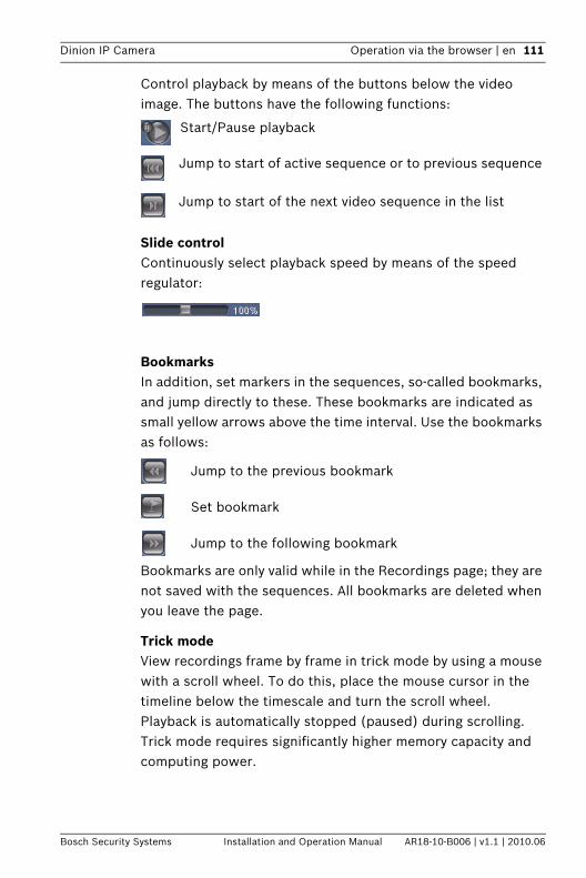
Dinion IP Camera Operation via the browser | en 111
Bosch Security Systems Installation and Operation Manual AR18-10-B006 | v1.1 | 2010.06
Control playback by means of the buttons below the video image. The buttons have the following functions:
Start/Pause playback
Jump to start of active sequence or to previous sequence
Jump to start of the next video sequence in the list
Slide controlContinuously select playback speed by means of the speed regulator:
BookmarksIn addition, set markers in the sequences, so-called bookmarks, and jump directly to these. These bookmarks are indicated as small yellow arrows above the time interval. Use the bookmarks as follows:
Jump to the previous bookmark
Set bookmark
Jump to the following bookmark
Bookmarks are only valid while in the Recordings page; they are not saved with the sequences. All bookmarks are deleted when you leave the page.
Trick modeView recordings frame by frame in trick mode by using a mouse with a scroll wheel. To do this, place the mouse cursor in the timeline below the timescale and turn the scroll wheel. Playback is automatically stopped (paused) during scrolling. Trick mode requires significantly higher memory capacity and computing power.

112 en | Troubleshooting Dinion IP Camera
AR18-10-B006 | v1.1 | 2010.06 Installation and Operation Manual Bosch Security Systems
11 Troubleshooting
11.1 Function testThe camera offers a variety of configuration options. Therefore, check that it works properly after installation and configuration. This is the only way to ensure that the camera will function as intended in the event of an alarm.Your check should include the following functions:– Can the camera be called up remotely?– Does the camera transmit all the data required?– Does the camera respond as desired to alarm events?– Is it possible to control peripheral devices, if necessary?
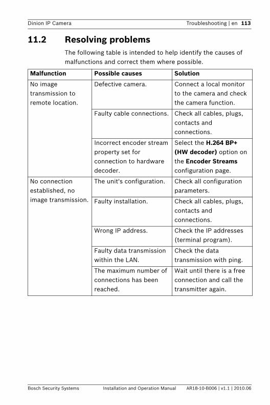
Dinion IP Camera Troubleshooting | en 113
Bosch Security Systems Installation and Operation Manual AR18-10-B006 | v1.1 | 2010.06
11.2 Resolving problemsThe following table is intended to help identify the causes of malfunctions and correct them where possible.
Malfunction Possible causes Solution
No image transmission to remote location.
Defective camera. Connect a local monitor to the camera and check the camera function.
Faulty cable connections. Check all cables, plugs, contacts and connections.
Incorrect encoder stream property set for connection to hardware decoder.
Select the H.264 BP+ (HW decoder) option on the Encoder Streams configuration page.
No connection established, no image transmission.
The unit's configuration. Check all configuration parameters.
Faulty installation. Check all cables, plugs, contacts and connections.
Wrong IP address. Check the IP addresses (terminal program).
Faulty data transmission within the LAN.
Check the data transmission with ping.
The maximum number of connections has been reached.
Wait until there is a free connection and call the transmitter again.
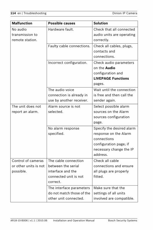
114 en | Troubleshooting Dinion IP Camera
AR18-10-B006 | v1.1 | 2010.06 Installation and Operation Manual Bosch Security Systems
No audio transmission to remote station.
Hardware fault. Check that all connected audio units are operating correctly.
Faulty cable connections. Check all cables, plugs, contacts and connections.
Incorrect configuration. Check audio parameters on the Audio configuration and LIVEPAGE Functions pages.
The audio voice connection is already in use by another receiver.
Wait until the connection is free and then call the sender again.
The unit does not report an alarm.
Alarm source is not selected.
Select possible alarm sources on the Alarm sources configuration page.
No alarm response specified.
Specify the desired alarm response on the Alarm connections configuration page; if necessary change the IP address.
Control of cameras or other units is not possible.
The cable connection between the serial interface and the connected unit is not correct.
Check all cable connections and ensure all plugs are properly fitted.
The interface parameters do not match those of the other unit connected.
Make sure that the settings of all units involved are compatible.
Malfunction Possible causes Solution
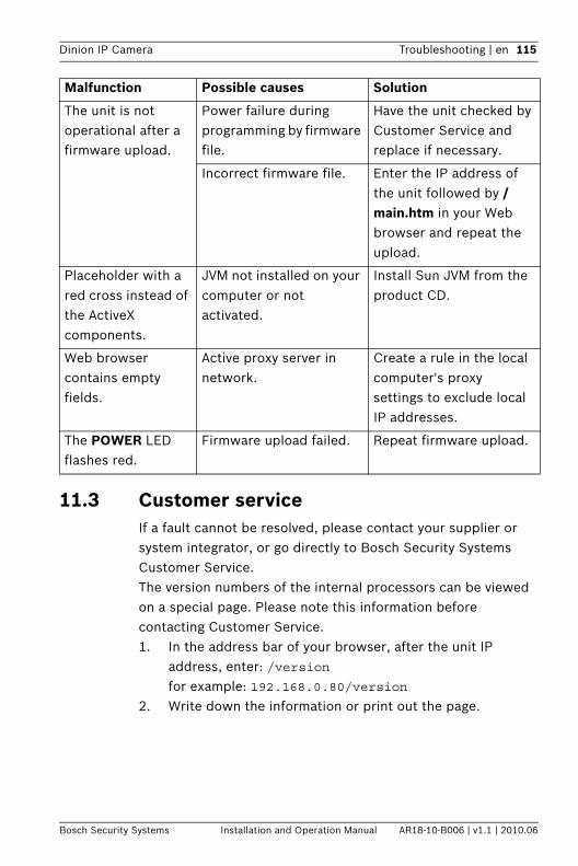
Dinion IP Camera Troubleshooting | en 115
Bosch Security Systems Installation and Operation Manual AR18-10-B006 | v1.1 | 2010.06
11.3 Customer serviceIf a fault cannot be resolved, please contact your supplier or system integrator, or go directly to Bosch Security Systems Customer Service.The version numbers of the internal processors can be viewed on a special page. Please note this information before contacting Customer Service.1. In the address bar of your browser, after the unit IP
address, enter: /versionfor example: 192.168.0.80/version
2. Write down the information or print out the page.
The unit is not operational after a firmware upload.
Power failure during programming by firmware file.
Have the unit checked by Customer Service and replace if necessary.
Incorrect firmware file. Enter the IP address of the unit followed by /main.htm in your Web browser and repeat the upload.
Placeholder with a red cross instead of the ActiveX components.
JVM not installed on your computer or not activated.
Install Sun JVM from the product CD.
Web browser contains empty fields.
Active proxy server in network.
Create a rule in the local computer's proxy settings to exclude local IP addresses.
The POWER LED flashes red.
Firmware upload failed. Repeat firmware upload.
Malfunction Possible causes Solution
116 en | Maintenance Dinion IP Camera
AR18-10-B006 | v1.1 | 2010.06 Installation and Operation Manual Bosch Security Systems
12 Maintenance
12.1 Testing the network connectionThe ping command can be used to check the connection between two IP addresses. This allows testing whether a device is active in the network.1. Open the DOS command prompt.2. Type ping followed by the IP address of the device.If the device is found, the response appears as " Reply from ... ", followed by the number of bytes sent and the transmission time in milliseconds. Otherwise, the device cannot be accessed via the network. This might be because:– The device is not properly connected to the network.
Check the cable connections in this case.– The device is not correctly integrated into the network.
Check the IP address, subnet mask, and gateway address.
12.2 Communication with Terminal ProgramData TerminalIf a camera cannot be found in the network or the connection to the network is interrupted, you can connect a data terminal to the camera for initial setup and for setting important parameters. The data terminal consists of a computer with a terminal program.You require a serial transmission cable with a 9-pin Sub-D plug to connect to the computer.
HyperTerminal, a communications accessory included with Microsoft Windows, can be used as the terminal program.
1. Disconnect the camera from the Ethernet network before working with the terminal program.
2. Connect the serial interface of the camera using any available serial interface on the computer.
Dinion IP Camera Maintenance | en 117
Bosch Security Systems Installation and Operation Manual AR18-10-B006 | v1.1 | 2010.06
Configuring the TerminalBefore the terminal program can communicate with the camera, the transmission parameters must be matched. Make the following settings for the terminal program:– 19,200 bps– 8 data bits– No parity check– 1 stop bit– No protocol
Command InputsAfter the connection has been established, you must log on to the camera to access the main menu. Other submenus and functions can be accessed using the on-screen commands.1. If necessary, turn off the local echo so that entered values
are not repeated on the display.2. Enter one command at a time.3. When you have entered a value, such as the IP address,
check the characters you have entered before pressing Enter to transfer the values to the camera.
Assigning an IP AddressBefore you can operate a camera in your network you must first assign it an IP address that is valid for your network.The following default address is preset at the factory: 192.168.0.11. Start a terminal program such as HyperTerminal.2. Enter the user name service. The terminal program
displays the main menu.3. Enter command 1 to open the IP menu.4. Enter 1 again. The terminal program displays the current IP
address and prompts you to enter a new IP address.5. Enter the desired IP address and press Enter. The terminal
program displays the new IP address.6. Use the displayed commands for any additional settings
you require.
118 en | Maintenance Dinion IP Camera
AR18-10-B006 | v1.1 | 2010.06 Installation and Operation Manual Bosch Security Systems
Note:You must reboot to activate the new IP address, a new subnet mask or a gateway IP address.
RebootBriefly interrupt the power supply to the camera for a reboot (disconnect the power supply unit from the mains supply and switch on again after a few seconds).
Additional ParametersYou can use the terminal program to check other basic parameters and modify them where necessary. Use the on-screen commands in the various submenus to do this.
12.3 Repairs
12.3.1 Transfer and disposalThe camera should only be passed on together with this installation guide. The unit contains environmentally hazardous materials that must be disposed of according to law. Defective or superfluous devices and parts should be disposed of professionally or taken to your local collection point for hazardous materials.
CAUTION! Never open the casing of the unit. The unit does not contain any user serviceable parts. Ensure that all maintenance or repair work is performed only by qualified personnel (electrical engineering or network technology specialists). In case of doubt, contact your dealer's technical service center.
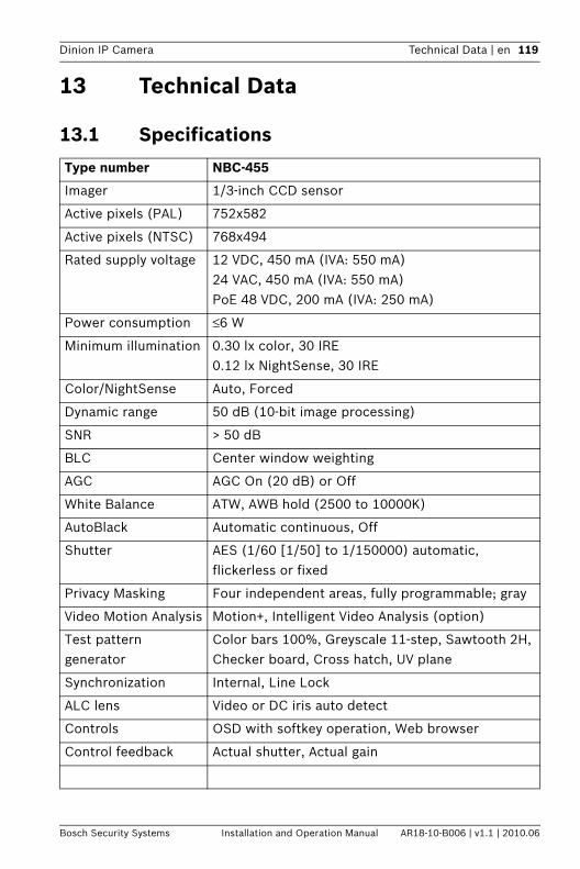
Dinion IP Camera Technical Data | en 119
Bosch Security Systems Installation and Operation Manual AR18-10-B006 | v1.1 | 2010.06
13 Technical Data
13.1 Specifications
Type number NBC-455
Imager 1/3-inch CCD sensor
Active pixels (PAL) 752x582
Active pixels (NTSC) 768x494
Rated supply voltage 12 VDC, 450 mA (IVA: 550 mA)24 VAC, 450 mA (IVA: 550 mA)PoE 48 VDC, 200 mA (IVA: 250 mA)
Power consumption ≤6 W
Minimum illumination 0.30 lx color, 30 IRE0.12 lx NightSense, 30 IRE
Color/NightSense Auto, Forced
Dynamic range 50 dB (10-bit image processing)
SNR > 50 dB
BLC Center window weighting
AGC AGC On (20 dB) or Off
White Balance ATW, AWB hold (2500 to 10000K)
AutoBlack Automatic continuous, Off
Shutter AES (1/60 [1/50] to 1/150000) automatic,flickerless or fixed
Privacy Masking Four independent areas, fully programmable; gray
Video Motion Analysis Motion+, Intelligent Video Analysis (option)
Test pattern generator
Color bars 100%, Greyscale 11-step, Sawtooth 2H, Checker board, Cross hatch, UV plane
Synchronization Internal, Line Lock
ALC lens Video or DC iris auto detect
Controls OSD with softkey operation, Web browser
Control feedback Actual shutter, Actual gain
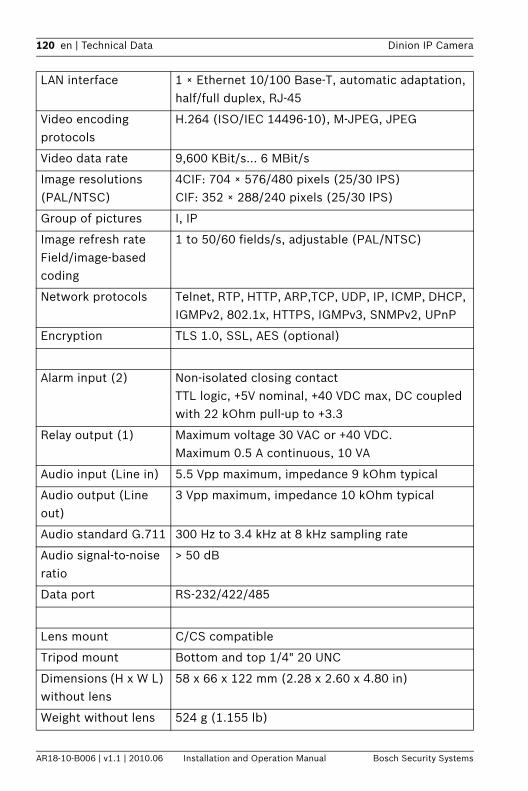
120 en | Technical Data Dinion IP Camera
AR18-10-B006 | v1.1 | 2010.06 Installation and Operation Manual Bosch Security Systems
LAN interface 1 × Ethernet 10/100 Base-T, automatic adaptation,half/full duplex, RJ-45
Video encoding protocols
H.264 (ISO/IEC 14496-10), M-JPEG, JPEG
Video data rate 9,600 KBit/s... 6 MBit/s
Image resolutions (PAL/NTSC)
4CIF: 704 × 576/480 pixels (25/30 IPS)CIF: 352 × 288/240 pixels (25/30 IPS)
Group of pictures I, IP
Image refresh rate Field/image-based coding
1 to 50/60 fields/s, adjustable (PAL/NTSC)
Network protocols Telnet, RTP, HTTP, ARP,TCP, UDP, IP, ICMP, DHCP, IGMPv2, 802.1x, HTTPS, IGMPv3, SNMPv2, UPnP
Encryption TLS 1.0, SSL, AES (optional)
Alarm input (2) Non-isolated closing contactTTL logic, +5V nominal, +40 VDC max, DC coupled with 22 kOhm pull-up to +3.3
Relay output (1) Maximum voltage 30 VAC or +40 VDC. Maximum 0.5 A continuous, 10 VA
Audio input (Line in) 5.5 Vpp maximum, impedance 9 kOhm typical
Audio output (Line out)
3 Vpp maximum, impedance 10 kOhm typical
Audio standard G.711 300 Hz to 3.4 kHz at 8 kHz sampling rate
Audio signal-to-noise ratio
> 50 dB
Data port RS-232/422/485
Lens mount C/CS compatible
Tripod mount Bottom and top 1/4" 20 UNC
Dimensions (H x W L) without lens
58 x 66 x 122 mm (2.28 x 2.60 x 4.80 in)
Weight without lens 524 g (1.155 lb)
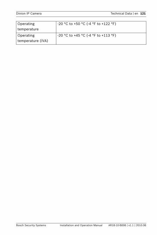
Dinion IP Camera Technical Data | en 121
Bosch Security Systems Installation and Operation Manual AR18-10-B006 | v1.1 | 2010.06
Operating temperature
-20 °C to +50 °C (-4 °F to +122 °F)
Operating temperature (IVA)
-20 °C to +45 °C (-4 °F to +113 °F)
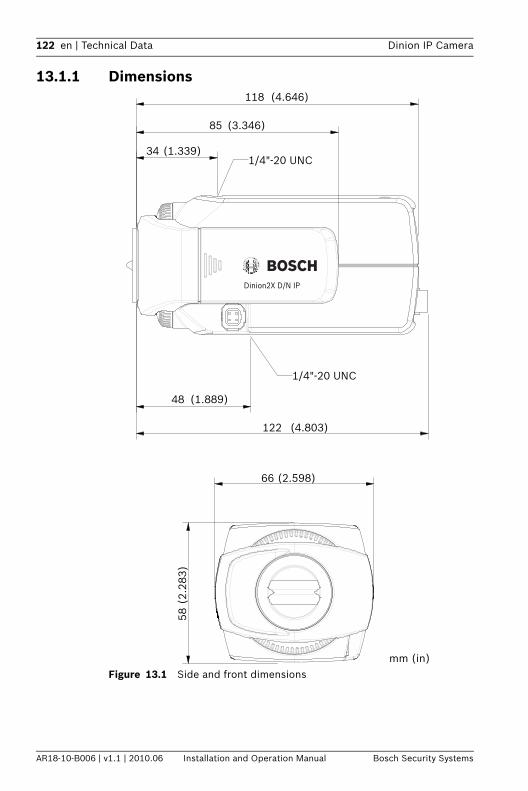
122 en | Technical Data Dinion IP Camera
AR18-10-B006 | v1.1 | 2010.06 Installation and Operation Manual Bosch Security Systems
13.1.1 Dimensions
Figure 13.1 Side and front dimensions
(2.
283)
58
(1.339)34
(3.346)85
(4.646)118
(4.803)122
(1.889)48
(2.598)66
1/4"-20 UNC
1/4"-20 UNC
mm (in)
Dinion2X D/N IP
Dinion IP Camera Technical Data | en 123
Bosch Security Systems Installation and Operation Manual AR18-10-B006 | v1.1 | 2010.06
13.1.2 Accessories
Recommended lensesLTC 3364/50 Varifocal Lens– 1/3-inch, 2.8 – 10 mm, DC-iris, CS-mount F1.4-360, 4-pinLTC 3374/21 Varifocal Lens – 1/3-inch, 5– 50 mm, DC-iris, CS-mount F1.4-360, 4-pinLTC 3364/60 Varifocal Lens – 1/3-inch, 3.5– 8 mm, DC-iris, CS-mount F1.4-360, 4-pinLTC 3364/41 Varifocal Lens – 1/3-inch, 2.8– 12 mm, DC-iris, CS-mount F1.4-360, 4-pinLTC 3374/50 Varifocal Lens I– 1/3-inch, 5– 50 mm, DC-iris, C-mount F1.7-360, 4-pin
LTC 3361/50 Varifocal Lens– 1/3-inch, 2.8 – 10 mm, manual-iris, CS-mount F1.4 – closeLTC 3371/21 Varifocal Lens – 1/3-inch, 5– 50 mm, manual-iris, CS-mount F1.4 – closeLTC 3361/32 Varifocal Lens – 1/3-inch, 3.0– 8 mm, manual-iris, CS-mount F1.0 – closeLTC 3361/41 Varifocal Lens – 1/3-inch, 2.8– 12 mm, manual-iris, CS-mount F1.4 – close
Power transformersUPA-2410-60 Power Supply– 120 VAC, 60 Hz, 24 VAC, 10 VA OutUPA-2430-60 Power Supply– 120 VAC, 60 Hz, 24 VAC, 30 VA OutUPA-2450-60 Power Supply– 120 VAC, 60 Hz, 24 VAC, 50 VA OutUPA-2420-50 Power Supply– 220 VAC, 50 Hz, 24 VAC, 20 VA OutUPA-2450-50 Power Supply– 220 VAC, 50 Hz, 24 VAC, 50 VA Out
Contact your Bosch representative for the latest available accessories.

124 en | Glossary Dinion IP Camera
AR18-10-B006 | v1.1 | 2010.06 Installation and Operation Manual Bosch Security Systems
Glossary
0…910/100Base-TIEEE-802.3 specification for 10 or 100 Mbps Ethernet.802.1x The IEEE 802.1x standard provides a general method for
authentication and authorization in IEEE-802 networks. Authentication is carried out via the authenticator, which checks the transmitted authentication information using an authentication server (see RADIUS server) and approves or denies access to the offered services (LAN, VLAN or WLAN) accordingly.
AARP Address Resolution Protocol: a protocol for mapping MAC and
IP addresses.
BBaud Unit of measure for the speed of data transmissionbps Bits per second, the actual data rate.
CCF CompactFlash: interface standard, for digital storage media
amongst other things. Used in computers in the form of CF cards, digital cameras and Personal Digital Assistants (PDA).
CIF Common Intermediate Format: video format with 352 × 288/240 pixels.
DDHCP Dynamic Host Configuration Protocol: uses an appropriate
server to enable dynamic assignment of an IP address and other configuration parameters to computers on a network (Internet or LAN).
DNS Domain Name Service: A service that stores domain names and translates them into Internet Protocol (IP) addresses.
Dinion IP Camera Glossary | en 125
Bosch Security Systems Installation and Operation Manual AR18-10-B006 | v1.1 | 2010.06
FFTP File Transfer Protocol: Used to transfer files between
computers on a network, such as the Internet.Full duplex Simultaneous data transmission in both directions (sending and
receiving).
GGBIC GigaBit Interface Converter: applied in network technology to
render interfaces flexible, for converting an electrical interface into an optical interface, for example. This enables flexible operation of an interface as a Gigabit Ethernet via twisted-pair cables or fiber optic cables.
GoP Group of Pictures: In MPEG video encoding, a group of pictures, or GoP, specifies the order in which intra-frames and inter-frames are arranged.
HH.264 Standard for high-efficiency video compression, based on the
predecessors MPEG-1, MPEG-2 and MPEG-4. H.264 typically achieves a coding efficiency around three times as high as MPEG-2. This means that comparable quality can be achieved at around a third of MPEG-2 data quantity.
HTTP Hypertext Transfer Protocol: protocol for transmitting data over a network.
HTTPS Hypertext Transfer Protocol Secure: encrypts and authenticates communication between Web server and browser.
IICMP Internet Control Message Protocol: One of the core protocols of
the Internet protocol suite. It is chiefly used by networked computers' operating systems to send error messages indicating, for instance, that a requested service is not available or that a host or router could not be reached.
ID Identification: a machine readable character string.
126 en | Glossary Dinion IP Camera
AR18-10-B006 | v1.1 | 2010.06 Installation and Operation Manual Bosch Security Systems
IEEE Institute of Electrical and Electronics Engineers: The world's leading professional association for the advancement of technology.
IGMP Internet Group Management Protocol: A communications protocol used to manage the membership of Internet Protocol multicast groups.
Internet ProtocolThe main protocol used on the Internet, normally in conjunction with the Transfer Control Protocol (TCP): TCP/IP.
IP See Internet Protocol.IP address A 4-byte number uniquely defining each unit on the Internet. It
is usually written in dotted decimal notation, for example "209.130.2.193"
iSCSI Internet Small Computer System Interface: Protocol that manages storage via a TCP/IP network. iSCSI enables access to stored data from everywhere in the network.
ISDN Integrated Services Digital Network: Comprised of digital telephony and data-transport services offered by regional telephone carriers. ISDN involves the digitization of the telephone network, which permits voice, data, text, graphics, music, video, and other source material to be transmitted over existing telephone wires.
JJPEG Joint Photographic Experts Group: The name of the committee
that created a standard for encoding still images.
KKbps Kilobits per second: the actual data rate.
LLAN Local Area Network: A communications network serving users
within a limited geographical area such as a building or university campus. It is controlled by a network operating system and uses a transfer protocol.
LUN Logical Unit Number: logical drive in iSCSI storage systems.
Dinion IP Camera Glossary | en 127
Bosch Security Systems Installation and Operation Manual AR18-10-B006 | v1.1 | 2010.06
MMAC Media Access Control: A quasi-unique identifier attached to
most network adapters (NICs). It is a number that acts like a name for a particular network adapter.
MIB Management Information Base: a collection of information for remote servicing using the SNMP protocol.
MPEG-4 A further development of MPEG-2 designed for transmitting audiovisual data at very low transfer rates (for example over the Internet).
MSS Maximum Segment Size: maximum byte figure for the user data in a data packet.
NNet mask A mask that explains which part of an IP address is the network
address and which part is the host address. It is usually written in dotted decimal notation, for example "255.255.255.192"
NTP Network Time Protocol: a standard for synchronizing computer system clocks via packet-based communication networks. NTP uses the connectionless network protocol UDP. This was developed specifically for enabling time to be reliably transmitted over networks with variable packet runtime (Ping).
OOF Optical Fiber: now used predominantly as the transmission
medium for line-borne telecommunication processes (glass fiber cable).
PParameters Values used for configuration.
QQCIF Quarter CIF: video format with 176 × 144/120 pixels (see CIF).
128 en | Glossary Dinion IP Camera
AR18-10-B006 | v1.1 | 2010.06 Installation and Operation Manual Bosch Security Systems
RRADIUS serverRemote Authentication Dial-In User Service: a client/server
protocol for the authentication, authorization and accounting of users with dial-up connections on a computer network. RADIUS is the de-facto standard for central authentication of dial-up connections via Modem, ISDN, VPN, Wireless LAN (see 802.1x) and DSL.
RFC 868 A Request For Comment protocol for synchronizing computer clocks over the Internet.
RS232/RS422/RS485 Recommended standards for serial data transmission. A communication interface for third party control, firmware upgrades, and service purposes for camera and DVR products.
RTP Realtime Transport Protocol: a transfer protocol for real-time video and audio.
SSFP Small Form-factor Pluggable: small, standardized module for
network connections, designed as a plug connector for high-speed network connections.
SNIA Storage Networking Industry Association: association of companies for defining the iSCSI standard.
SNMP Simple Network Management Protocol: a protocol for network management, for managing and monitoring network components.
SNTP Simple Network Time Protocol: a simplified version of NTP (see NTP).
SSL Secure Sockets Layer: an encryption protocol for data transmission in IP-based networks. The predecessor to TLS (see TLS).
Subnet maskSee Net mask.
TTCP Transfer Control ProtocolTelnet Login protocol with which users can access a remote computer
(Host) on the Internet or local area network (LAN) connections.
Dinion IP Camera Glossary | en 129
Bosch Security Systems Installation and Operation Manual AR18-10-B006 | v1.1 | 2010.06
TLS Transport Layer Security: TLS 1.0 and 1.1 and the standard advanced developments of SSL 3.0 (see SSL).
TTL Time-To-Live: life cycle of a data packet in station transfers.
UUDP User Datagram Protocol: One of the core protocols of the
Internet Protocol suite.URL Uniform Resource Locator: Previously Universal Resource
Locator. The unique address for a file that is accessible on the Internet.
UTP Unshielded Twisted Pair: A variant of twisted pair cabling, UTP cable is not surrounded by any shielding.
WWAN Wide Area Network: A long distance link used to extend or
connect remotely located local area networks.
130 en | Glossary Dinion IP Camera
AR18-10-B006 | v1.1 | 2010.06 Installation and Operation Manual Bosch Security Systems

Bosch Security Systems
www.boschsecurity.com © Bosch Security Systems, 2010