MG-GY 6933 Advanced Mechatronics Final Report
25
MG-GY 6933 Advanced Mechatronics Final Report Instructor: Professor Vikram Kapila Team: Kshitij Jindal (kj1290) Yang Liu (yl6101) Shiheng Wang (sw4018) 2019.05.16
Transcript of MG-GY 6933 Advanced Mechatronics Final Report
MG-GY 6933 Advanced Mechatronics
Final Report
Instructor: Professor Vikram Kapila
Team:
Kshitij Jindal (kj1290) Yang Liu (yl6101)
Shiheng Wang (sw4018)
2019.05.16
Table of Content Overview 3
1.1 Goal 3 1.2 Objective of the Project 3 1.3 Measurement 4
Introduction 5 2.1 Control Policy 6
Development 7 4.1 Phase I -- Arduino 7 4.2 Phase II -- Propeller 7 4.3 Phase III -- Raspberry Pi 8
4.3.1 OpenCV & Camera 8 a. Real-time Face detection 9 b. Distance detection 10 c. Color Detection 13
4.3.2 Communication between R-Pi and Arduino 15
Conclusion and Result 17
At current stage, the direction control was not implemented yet. But we can use Picame do real-time face detection, distance detection and color detection. Through the camera, can return value to raspberry pi and send it to arduino. At the sem time, we can get the value from sensors which connected to Arduino by using Raspberry Pi. The problem is, how to make them work simultaneously and when datas are huge, how to guarantee obtain them accurately. 17
Future Works 17
Reference 18
Appendix[Done] 19 Raspberry pi 3B 19 Arduino Uno 20 ELP High Speed 120fps PCB USB2.0 Webcam 21 L298N H-bridge Motor Controller 23 Step-down DC-DC Converter Module for Raspberry Pi 24 Rotary Encoder & Wheel Set 24 DC 3V - 6V Dual Axis Gear Motor 25
1
Table of Figures Figure 1. Grid workspace with objective and obstacle. 4 Figure 2. Ideal Work Space 5 Figure 3. Control Policy 6 Figure 4. Single Face Detected 10 Figure 5. Multiple Different Format of Face Detected 10 Figure 6. Triangle Similarity 11 Figure 7. Camera with OpenCV Detecting Moving Face and Returning Distance 12 Figure 8(a). Camera detected distance 12 Figure 8(b). Measured distance by ruler 12 Figure 9(a). Test code for setting HSV trackbar 13 Figure 9(b). Test code for finding HSV threshold 13 Figure 10. Finding the Biggest Contour 13 Figure 11(a). Threshold adjustment 14 Figure 11(b).Threshold adjustment 14 Figure 12. Threshold parameters found 15 Figure 13. PiConfig 16 Figure 14. Verify Arduino port number 16
2

Overview
1.1 Goal
The goal of this project is to prototype of an autonomous delivery bot, which represents an
autonomous waiter in real life. The goal of the project includes:
● Allow users to control the robot by sending command of objective location
● To build a small size bot which can move to target location and stop when encounters
obstacles in midway.
1.2 Objective of the Project
The objective of this project includes:
● A defined test environment and workspace for prototype.
● A small scale delivery bot, which can accurately navigate but not yet with items
pick-and-place function.
● Develop an algorithm for detecting the distance from the bot to objective
location/obstacle using OpenCV and camera, and showing the distance with centimeter
unit
● Set block with human front face picture as objective location, and colored (blue) box as
obstacle, the bot would start to move when it detect the objective location, but stop while
detect obstacle.
● A screen mounted on the bot showing the front view captured by the bot.
3

1.3 Measurement
The success of the system would be measured by following factors:
● Communicate and control the arduino through sending command to the R-Pi terminal.
● The distance detected by the camera and OpenCV matches with the distance manually
measured on the grid paper coordinate.
● Circle and contour out the objective detected, and show in real-time on the screen
mounted on the screen.
Figure 1. Grid workspace with objective and obstacle.
4
Introduction
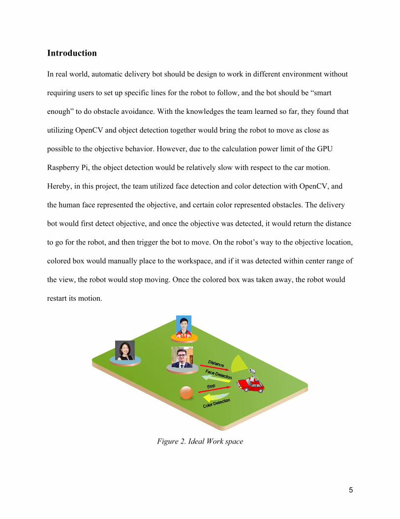
In real world, automatic delivery bot should be design to work in different environment without
requiring users to set up specific lines for the robot to follow, and the bot should be “smart
enough” to do obstacle avoidance. With the knowledges the team learned so far, they found that
utilizing OpenCV and object detection together would bring the robot to move as close as
possible to the objective behavior. However, due to the calculation power limit of the GPU
Raspberry Pi, the object detection would be relatively slow with respect to the car motion.
Hereby, in this project, the team utilized face detection and color detection with OpenCV, and
the human face represented the objective, and certain color represented obstacles. The delivery
bot would first detect objective, and once the objective was detected, it would return the distance
to go for the robot, and then trigger the bot to move. On the robot’s way to the objective location,
colored box would manually place to the workspace, and if it was detected within center range of
the view, the robot would stop moving. Once the colored box was taken away, the robot would
restart its motion.
Figure 2. Ideal Work space
5

2.1 Control Policy
Figure 3. Control Policy
6

Development
4.1 Phase I -- Arduino
For the first phase, the team built a car with Arduino as a microcontroller. Since the objective
was to deliver, the team chose Ackermann Steering which prevents slipping. The forward
kinematics was done and then Proportional gain controller was applied to make the robot reach
the objective. Encoder was used as the inly sensor in this phase, which detected rotation of each
rear wheel and then a mean velocity was calculated. Through Euler integration, the current
position was estimated and then the distance to the goal position was re-calculated. The gain for
the steering angle and DC motor speed was adjusted based on trial and error.
4.2 Phase II -- Propeller
In the second phase, the team integrated rotary encoder and parallax accelerometer to improve
the localization of the car. The team implemented Extended Kalman Filter to improve the results
obtained by both the sensors. Accelerometer was used in the prediction step and values from the
rotary encoder was used in the update step.
7
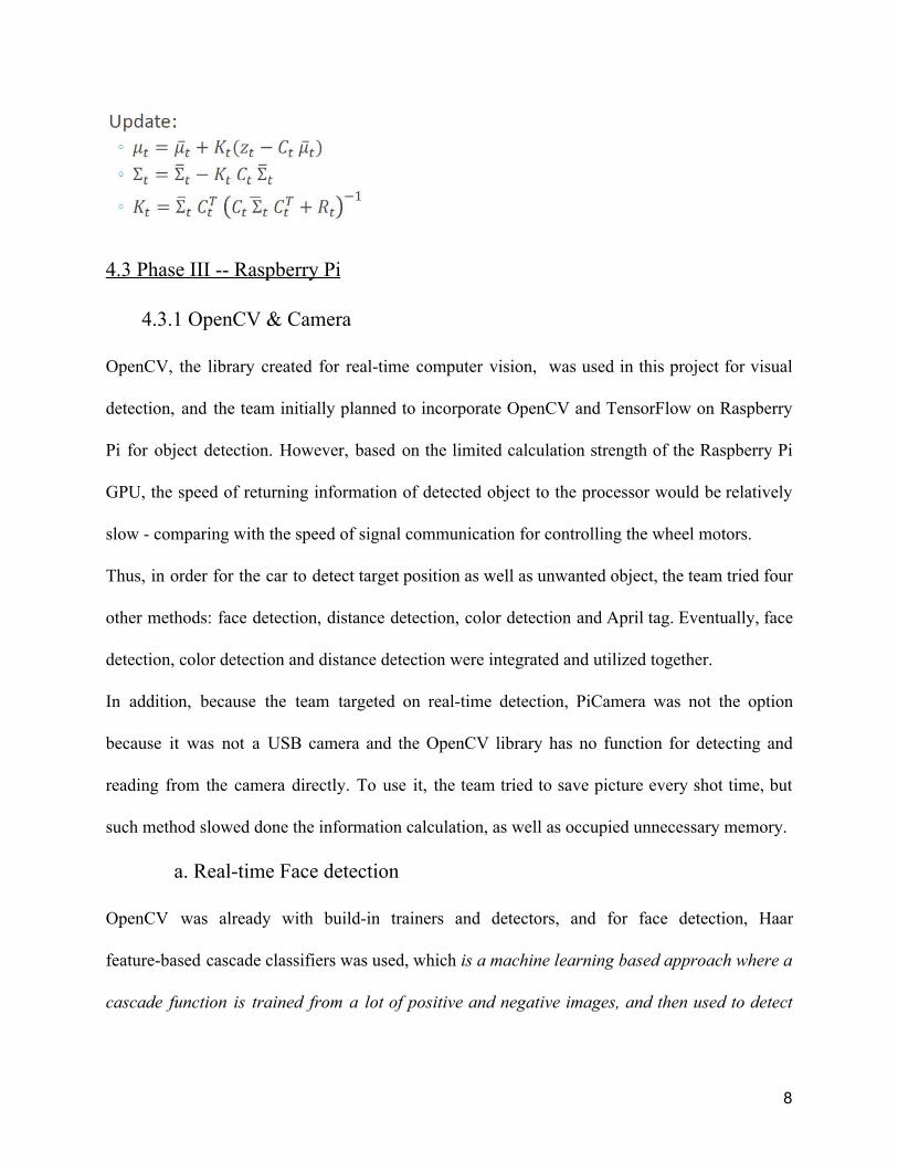
4.3 Phase III -- Raspberry Pi
4.3.1 OpenCV & Camera
OpenCV, the library created for real-time computer vision, was used in this project for visual
detection, and the team initially planned to incorporate OpenCV and TensorFlow on Raspberry
Pi for object detection. However, based on the limited calculation strength of the Raspberry Pi
GPU, the speed of returning information of detected object to the processor would be relatively
slow - comparing with the speed of signal communication for controlling the wheel motors.
Thus, in order for the car to detect target position as well as unwanted object, the team tried four
other methods: face detection, distance detection, color detection and April tag. Eventually, face
detection, color detection and distance detection were integrated and utilized together.
In addition, because the team targeted on real-time detection, PiCamera was not the option
because it was not a USB camera and the OpenCV library has no function for detecting and
reading from the camera directly. To use it, the team tried to save picture every shot time, but
such method slowed done the information calculation, as well as occupied unnecessary memory.
a. Real-time Face detection
OpenCV was already with build-in trainers and detectors, and for face detection, Haar
feature-based cascade classifiers was used, which is a machine learning based approach where a
cascade function is trained from a lot of positive and negative images, and then used to detect
8

objects in other images. [1] The pre-trained Haar cascade classifiers was stored in the XML file,
and then with following python code[1], it could be load for the use of face detection.
import numpy as np import cv2 as cv face_cascade = cv.CascadeClassifier('haarcascade_frontalface_default.xml')
After loading the classifier, following code was utilized to setup the camera start video stream.
Because the USB camera was used for real-time video capturing, instead of using img =
cv.imread('sachin.jpg')for reading an image, following command was utilized:
Once the video was captured, it was converted into grayscale with following code:
After that, it was load into the classifier, and wherever a face was detected, a rectangle would be
drawn around with following code. In addition, the screen would return “found a face” as a
output signal, which could be used as a trigger and sent to Arduino for wheel motor control.
Eventually, with following code, a video stream window would be showing on the screen.
9

In Figure 3. below, there’s one face of real human being detected, and in Figure 4. there was the
other face detected, which was a picture instead of real person in front of the camera. That
indicate the success of real-time face detection.
Figure 4. Single Face Detected Figure 5. Multiple different format of face detected
b. Distance detection
For distance measurement, the Triangle Similarity[2] method demonstrated in Figure 5 was
utilized. To use this method, a picture with known width (W) and known distance (D) to the
camera was taken at first. Then get the pixels (P) of the known width, and calculate the focal
length (F) of the camera using Equation 1 on next page.
Figure 6. Triangle Similarity
10
F = (P * D) / W (Equation 1)
After that, the image could be moved closer to the camera, which brought the distance change,
and the newer distance would be D’, which could be calculated using Equation 2 below.
D’ = (F * W) / P (Equation 2)
In this project, the camera was calibrated based on a human face (W*H ~18cm*13cm) printed on
paper, which was ~7cm*5cm. When doing the calculation and coding, the team read similar
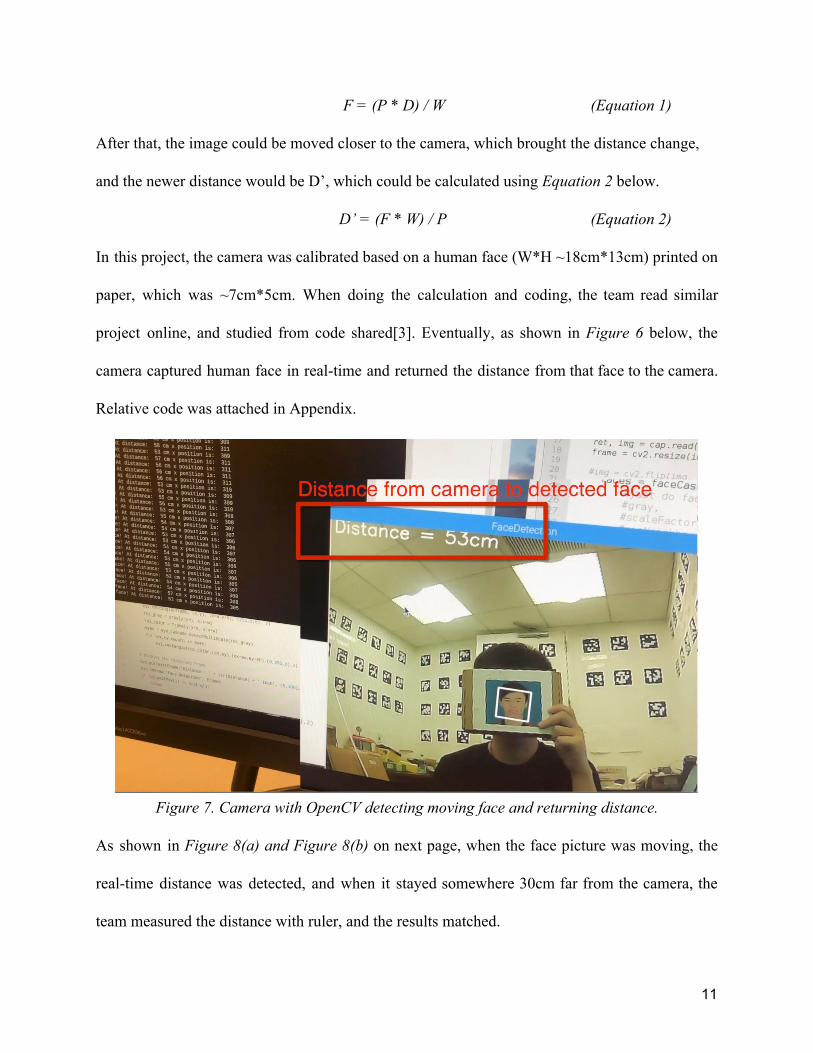
project online, and studied from code shared[3]. Eventually, as shown in Figure 6 below, the
camera captured human face in real-time and returned the distance from that face to the camera.
Relative code was attached in Appendix.
Figure 7. Camera with OpenCV detecting moving face and returning distance.
As shown in Figure 8(a) and Figure 8(b) on next page, when the face picture was moving, the
real-time distance was detected, and when it stayed somewhere 30cm far from the camera, the
team measured the distance with ruler, and the results matched.
11

Figure 8(a) Camera detected distance Figure 8(b) Measured distance by ruler
c. Color Detection
The video capture process of color detection was the same as face and distance detection. After
capturing videos, the next step was to turn video captured from RGB colored profile into HSV
profile, and then create a mask based on the HSV range. Because the camera and environment
difference, the HSV threshold could be different, and HSV for standard color might not be
utilized specifically for this project. Thus, the first step was to run following code find the HSV
range for color used in this project.
Figure 9(a) Test code for setting HSV trackbar
Figure 9(b). Test code for finding HSV threshold
12

The purpose of this HSV mask was to filter the video, and made it easier for contour finding.
With such a mask, the contour of objective color could be found and returned in array list.
However, while there would be both noise and more than one object with target color, so a set of
additional command was added to find the biggest contour. There’s one more thing needs to be
pointed out: the online tutorials the team found for color detection was detection color from
single image, of which there’s always objective color, but it ignore the condition whenever
there’s no objective color detected, in which the command for find maximum contour would
crash. To fix that, try-except structure was implemented as shown below in Figure 9.
Figure 10. Finding the Biggest Contour
With running above code, a series of window would show up, including a colorTest window
with trackbar for manually adjusting HSV range, a mask-plain window, original frame window
and a result window with contours in yellow color and biggest contour in green. As shown in
Figure 10(a) and Figure 10(b), the grayscale mask-plain window would be representing the
color captured while the threshold parameters were adjusted.
13
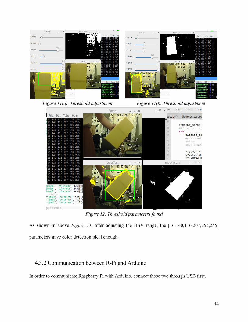
Figure 11(a). Threshold adjustment Figure 11(b).Threshold adjustment
Figure 12. Threshold parameters found
As shown in above Figure 11, after adjusting the HSV range, the [16,140,116,207,255,255]
parameters gave color detection ideal enough.
4.3.2 Communication between R-Pi and Arduino
In order to communicate Raspberry Pi with Arduino, connect those two through USB first.
14
Therefore, sensors, motors, and actuators which connected to Arduino can send values to and
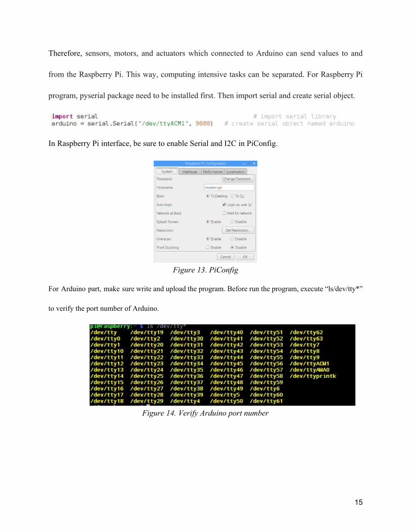
from the Raspberry Pi. This way, computing intensive tasks can be separated. For Raspberry Pi
program, pyserial package need to be installed first. Then import serial and create serial object.
In Raspberry Pi interface, be sure to enable Serial and I2C in PiConfig.
Figure 13. PiConfig
For Arduino part, make sure write and upload the program. Before run the program, execute “ls/dev/tty*”
to verify the port number of Arduino.
Figure 14. Verify Arduino port number
15

Conclusion and Result
At current stage, the direction control was not implemented yet. However, real-time face
detection, distance detection and color detection can be done by using Picamera. Through the
camera, value can be returned to raspberry pi and send it to arduino. At the same time, value can
obtained from sensors which connected to Arduino by using Raspberry Pi. The problem is, how
to make them work simultaneously and when datas are huge, how to guarantee obtain them
accurately.
Future Works
For future work, additional calculation and programming could be added to get the off-center
angel of the objective detected. As shown below in Figure 15, with x,y distance measured, the
off-center angle could be calculated. Similarly, for current stage, as long as there’s objective item
captured by the camera, no matter the object was just on the border or at the center. For future
stage, since the x pixel position could be detected, a range could be defined and only when the
location of detected object was in that range, the R-Pi would taking the detected item as
objective.
Figure 15. Off-center angle Figure 16. Narrow the edge
16

Reference
[1] Face Haar Cascade: https://docs.opencv.org/3.4.1/d7/d8b/tutorial_py_face_detection.html [2] Distance measurement: https://www.pyimagesearch.com/2015/01/19/find-distance-camera-objectmarker-using-python-opencv/ [3] Face detection & distance: https://www.youtube.com/watch?v=xfSw3mC35qU [4] Color detection: https://www.bluetin.io/opencv/object-detection-tracking-opencv-python/ [5] TensorFlow: https://github.com/EdjeElectronics/TensorFlow-Object-Detection-on-the-Raspberry-Pi
17

Appendix[Done]
- Raspberry pi 3B
https://www.raspberrypi.org/products/raspberry-pi-3-model-b/ ● Quad Core 1.2GHz Broadcom BCM2837 64bit CPU
● 1GB RAM
● BCM43438 wireless LAN and Bluetooth Low Energy (BLE) on board
18

● 100 Base Ethernet
● 40-pin extended GPIO
● 4 USB 2 ports
● 4 Pole stereo output and composite video port
● Full size HDMI
● CSI camera port for connecting a Raspberry Pi camera
● DSI display port for connecting a Raspberry Pi touchscreen display
● Micro SD port for loading your operating system and storing data
● Upgraded switched Micro USB power source up to 2.5A
- Arduino Uno
https://store.arduino.cc/usa/arduino-uno-rev3
Microcontroller ATmega328
Operating Voltage 5V
Input Voltage (recommended) 7-12V
Input Voltage (limit) 6-20V
Digital I/O Pins 14 (of which 6 provide PWM output)
PWM Digital I/O Pins 6
Analog Input Pins 6
DC Current per I/O Pin 20 mA
19

DC Current for 3.3V Pin 50 mA
Flash Memory 32 KB (ATmega328P) of which 0.5 KB used by bootloader
SRAM 2 KB (ATmega328P)
EEPROM 1 KB (ATmega328P)
Clock Speed 16 MHz
LED_BUILTIN 13
Length 68.6 mm
Width 53.4 mm
Weight 25 g
- ELP High Speed 120fps PCB USB2.0 Webcam
Board 2 Mega Pixels 1080P OV2710 CMOS Camera Module With 2.1mm Lens ELP-USBFHD01M-L21
http://www.webcamerausb.com/elp-high-speed-120fps-pcb-usb20-webcam-board-2-mega-pixels-1080p-ov2710-cmos-camera-module-with-21mm-lens-elpusbfhd01ml21-p-78.html
Model ELP-USBFHD01M-L21
Sensor OV2710
Sensor Size 1/2.7 inch
Pixel Size 3μm x 3μm
image area 5856 μm x 3276 μm
Max. Resolution FULL HD 1920(H)X1080(V)
Compression format MJPEG / YUV2(YUYV)
20
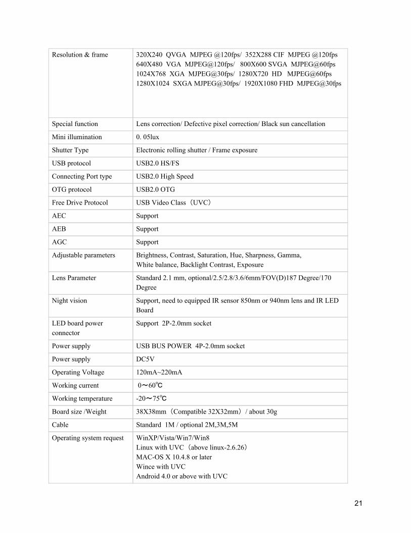
Resolution & frame 320X240 QVGA MJPEG @120fps/ 352X288 CIF MJPEG @120fps 640X480 VGA MJPEG@120fps/ 800X600 SVGA MJPEG@60fps 1024X768 XGA MJPEG@30fps/ 1280X720 HD MJPEG@60fps 1280X1024 SXGA MJPEG@30fps/ 1920X1080 FHD MJPEG@30fps
Special function Lens correction/ Defective pixel correction/ Black sun cancellation
Mini illumination 0. 05lux
Shutter Type Electronic rolling shutter / Frame exposure
USB protocol USB2.0 HS/FS
Connecting Port type USB2.0 High Speed
OTG protocol USB2.0 OTG
Free Drive Protocol USB Video Class(UVC)
AEC Support
AEB Support
AGC Support
Adjustable parameters Brightness, Contrast, Saturation, Hue, Sharpness, Gamma, White balance, Backlight Contrast, Exposure
Lens Parameter Standard 2.1 mm, optional/2.5/2.8/3.6/6mm/FOV(D)187 Degree/170 Degree
Night vision Support, need to equipped IR sensor 850nm or 940nm lens and IR LED Board
LED board power connector
Support 2P-2.0mm socket
Power supply USB BUS POWER 4P-2.0mm socket
Power supply DC5V
Operating Voltage 120mA~220mA
Working current 0~60℃
Working temperature -20~75℃
Board size /Weight 38X38mm(Compatible 32X32mm)/ about 30g
Cable Standard 1M / optional 2M,3M,5M
Operating system request WinXP/Vista/Win7/Win8 Linux with UVC(above linux-2.6.26) MAC-OS X 10.4.8 or later Wince with UVC Android 4.0 or above with UVC
21

- L298N H-bridge Motor Controller
https://www.amazon.com/H-bridge-Controller-DROK-Stepper-Regulator/dp/B07MR2S1YX
● Parameter:
● Chip: L298N
● Logic voltage: 5V
● Logic current 0mA-36mA
● Storage Temperature: -20 ℃ to ℃ to +135
● Operating mode: H-bridge driver (dual)
● Drive voltage: 5V-35V
● Drive current: 2A (MAX single bridge)
● Maximum power: 25W
● Dimensions: 43x43x27mm
22

- Step-down DC-DC Converter Module for Raspberry Pi
- https://www.sunfounder.com/step-down-dc-dc-converter-module-for-raspberry-pi.html
● With a USB port; 4 pins for output voltage
● With power indicator light
● Input voltage: 5V – 40V
● Output voltage: DC 5V; output current: 2A
● PCB size: 4.4 x 2.7 cm
- Rotary Encoder & Wheel Set
https://tinkersphere.com/parts-components/1472-rotary-encoder-wheel-set.html
● Number of notches per wheel: 20
● Input Voltage(VCC): 4.5V to 5.5V DC
● Input Current: 25mA
● Measurement Frequency: 100 kHz
● Signal Output: Square Wave (GND to VCC)
● Encoder Size: 24mm
● Pinout: ○ 5V: Power ○ GND: Ground
23

○ OUT: Signal (to your Arduino or other microcontroller)
- DC 3V - 6V Dual Axis Gear Motor
https://usa.banggood.com/DC-3V-6V-Dual-Axis-Gear-Motor-2-Axis-TT-Motor-Reducer-Motor-p-916210.html?gmcCountry=US¤cy=USD&createTmp=1&utm_source=googleshopping&utm_medium=cpc_bgcs&utm_content=garman&utm_campaign=pla-usg-ele-diy1-pc&gclid=CjwKCAjw8e7mBRBsEiwAPVxxiO_DKQviUrFcuuWQGQx8k92F2M30XK_S1KEEdW2Gd5qJC2XZ7zkSwxoCMdIQAvD_BwE&cur_warehouse=CN
● Strong magnetic with anti-interference
● Double axis gear motor
● Reduction ratio: 1:48
● Working voltage: 3V ~ 6V
● Unloads current: ≤200mA @ 6V, ≤150mA @ 3V
● Unloads speed: 200 ± 10%RPM @ 6V, 90 ± 10%RPM @ 3V
24