ME 6702 -Mechatronics - PITpit.ac.in/pitnotes/uploads/ME6702_I.pdf · 2019-07-15 · Introduction...
113
UNIT I ME 6702 -Mechatronics
Transcript of ME 6702 -Mechatronics - PITpit.ac.in/pitnotes/uploads/ME6702_I.pdf · 2019-07-15 · Introduction...
UNIT I
ME 6702 -Mechatronics
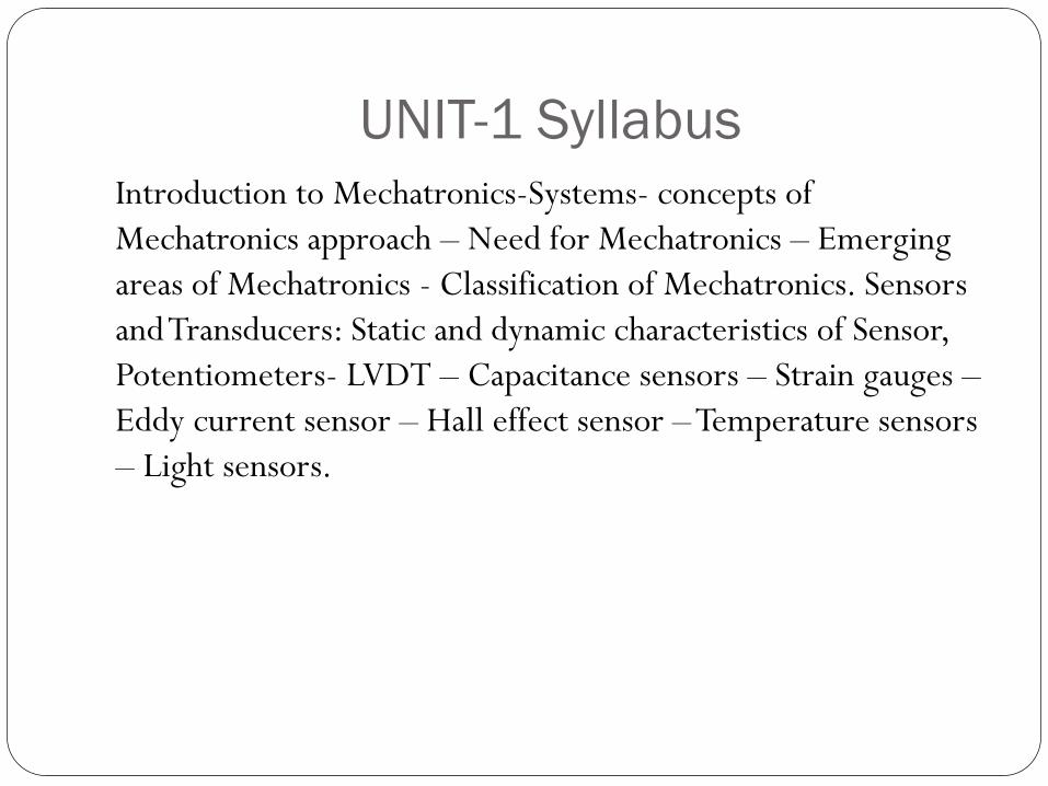
UNIT-1 Syllabus
Introduction to Mechatronics-Systems- concepts of
Mechatronics approach – Need for Mechatronics – Emerging
areas of Mechatronics - Classification of Mechatronics. Sensors
and Transducers: Static and dynamic characteristics of Sensor,
Potentiometers- LVDT – Capacitance sensors – Strain gauges –
Eddy current sensor – Hall effect sensor – Temperature sensors
– Light sensors.

What is Mechatronics
Mechatronics is the synergistic combination of mechanical
engineering (“mecha” for mechanisms), electronic engineering
(“tronics” for electronics), and software engineering.
The word “mechatronics” was first coined by Mr. Tetsuro
Moria, a senior engineer of a Japanese company, Yaskawa, in
1969.

Mechatronics System
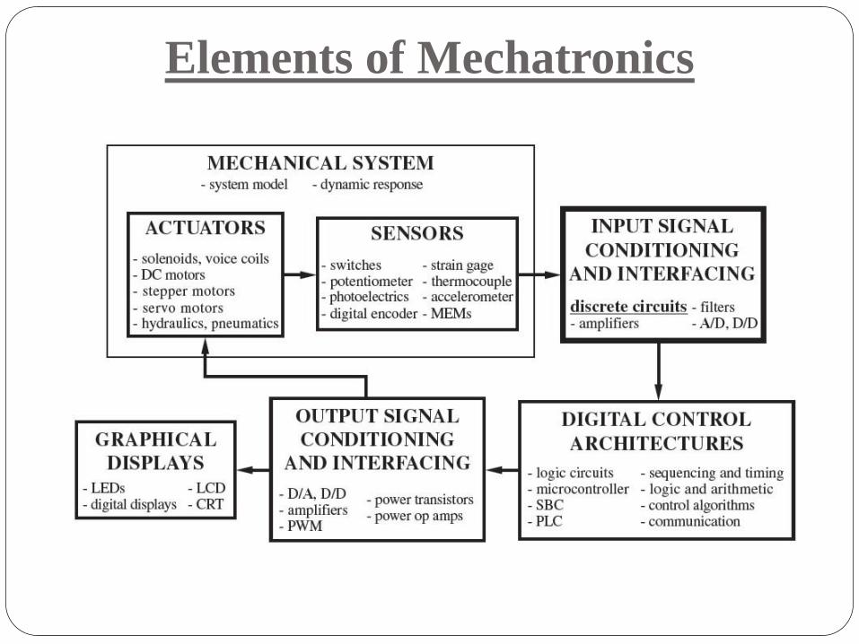
Elements of Mechatronics

Why Mechatronics ?
Advantages & limitations of mechanical systems
Advantages & limitations of electronic systems
Role of computers
Systems
A system can be thought of as a box or block diagram which
has an input and an output where we are concerned not with
what goes on inside the box but with only the relationship
between the output and the input.
Classification of Mechatronics
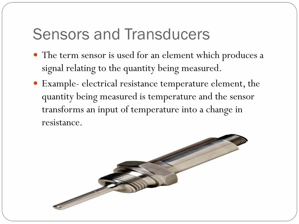
Sensors and Transducers
The term sensor is used for an element which produces a
signal relating to the quantity being measured.
Example- electrical resistance temperature element, the
quantity being measured is temperature and the sensor
transforms an input of temperature into a change in
resistance.

Sensors and Transducers
The term transducer is often used in place of the term
sensor.
Transducers are defined as elements that when subject to
some physical change experience related change.

Measurement Characteristics (Performance of
terminology)
Range: Difference between the maximum and minimum value of the sensed parameter
Resolution: The smallest change the sensor can differentiate
Accuracy: Difference between the measured value and the true value
Precision: Ability to reproduce the results repeatedly with a given accuracy
Sensitivity: Ratio of change in output to a unit change of the input
Zero offset: A nonzero value output for no input

Measurement Characteristics
Linearity: Percentage of deviation from the best-fit linear
calibration curve
Zero Drift: The departure of output from zero value over a
period of time for no input
Response time: The time lag between the input and output
Operating temperature: The range in which the sensor
performs as specified
Deadband: The range of input for which there is no output

Range & Resolution
Range: The range (or span) of a sensor is the difference between the
minimum (or most negative) and maximum inputs that will give a
valid output. Range is typically specified by the manufacturer of the
sensor.
For example, a common type K thermocouple has a range of
800°C (from −50°C to 750°C).
Resolution: The resolution of a sensor is the smallest increment of
input that can be reliably detected. Resolution is also frequently
known as the least count of the sensor.
The resolution of analog sensors is usually limited only by low-
level electrical noise and is often much better than equivalent
digital sensors.
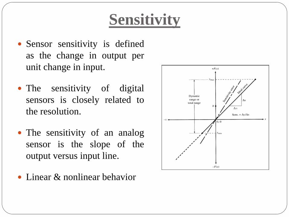
Sensitivity
Sensor sensitivity is defined
as the change in output per
unit change in input.
The sensitivity of digital
sensors is closely related to
the resolution.
The sensitivity of an analog
sensor is the slope of the
output versus input line.
Linear & nonlinear behavior
Error
Error is the difference between a measured value and the true input
value.(measured value – true value)
Two types of errors:
Bias (or systematic) errors and
Precision (or random) errors.
Bias errors can be further subdivided into
Calibration errors (a zero or null point error is a common type of
bias error created by a nonzero output value when the input is
zero),
Loading errors (adding the sensor to the measured system changes
the system),
errors due to sensor sensitivity to variables other than the desired
one (e.g., temperature effects on strain gages).

Repeatability & Reproducibility
A measurement system must first be accurate, precise &
repeatable before it can be reproducible.
Repeatability refers to a sensor‟s ability to give identical outputs
for the same input
Precision (or random) errors cause a lack of repeatability
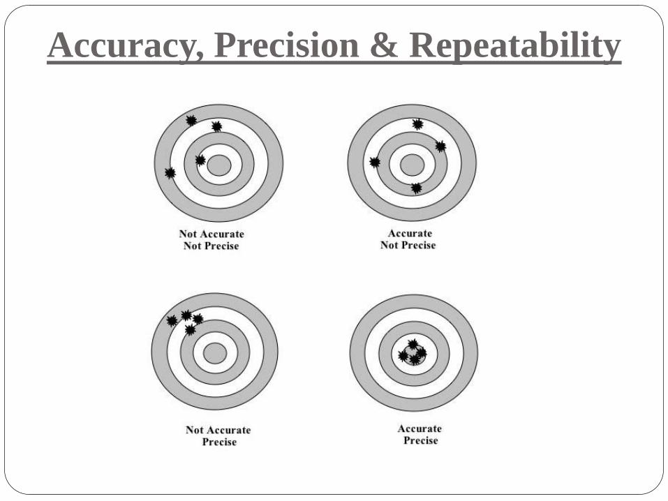
Accuracy, Precision & Repeatability

Saturation, Dead-Band
Saturation: All real actuators have some maximum output
capability, regardless of the input.
Deadband: The dead band is typically a region of input close to
zero at which the output remains zero. Once the input travels
outside the dead band, then the output varies with input.
0 1 2 3 4 5 6 7 8 9 10-2
-1.5
-1
-0.5
0
0.5
1
1.5
2
Time in Seconds
Forc
e in N
ew
ton
Comparison between Un-saturated & Saturdated Signal
Desired Output
Saturated Output

Basic Principle of Sensor / Transduction
Measuring
Parameter Useful Signal Conversion Device
Voltage, current,
capacitance
Displacement,
Temperature,
Pressure etc….
Sensor is a device that when exposed to a physical phenomenon
(temperature, displacement, force, etc.) produces a proportional output signal
(electrical, mechanical, magnetic, etc.).
Transducer is a device that converts one form of (energy) signal into another
form of (energy) signal.
Sensors
Position Sensors:
Potentiometer
LVDT
Encoders

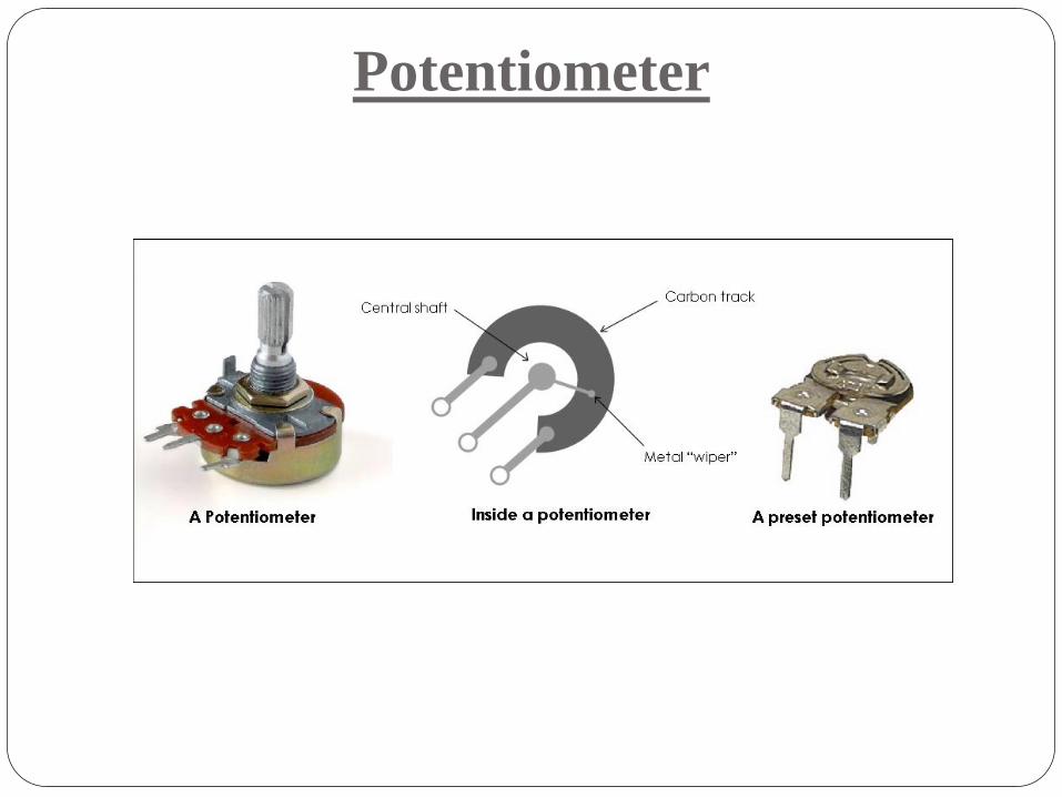
Potentiometer
A rotary potentiometer is a variable resistance device that can
be used to measure angular position
Through voltage division the change in resistance can be used
to create an output voltage that is directly proportional to the
input displacement.
Potentiometer
Potentiometer
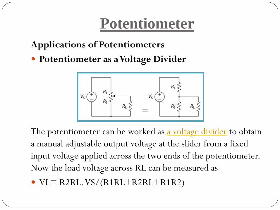
Applications of Potentiometers
Potentiometer as a Voltage Divider
The potentiometer can be worked as a voltage divider to obtain
a manual adjustable output voltage at the slider from a fixed
input voltage applied across the two ends of the potentiometer.
Now the load voltage across RL can be measured as
VL= R2RL. VS/(R1RL+R2RL+R1R2)
Potentiometer
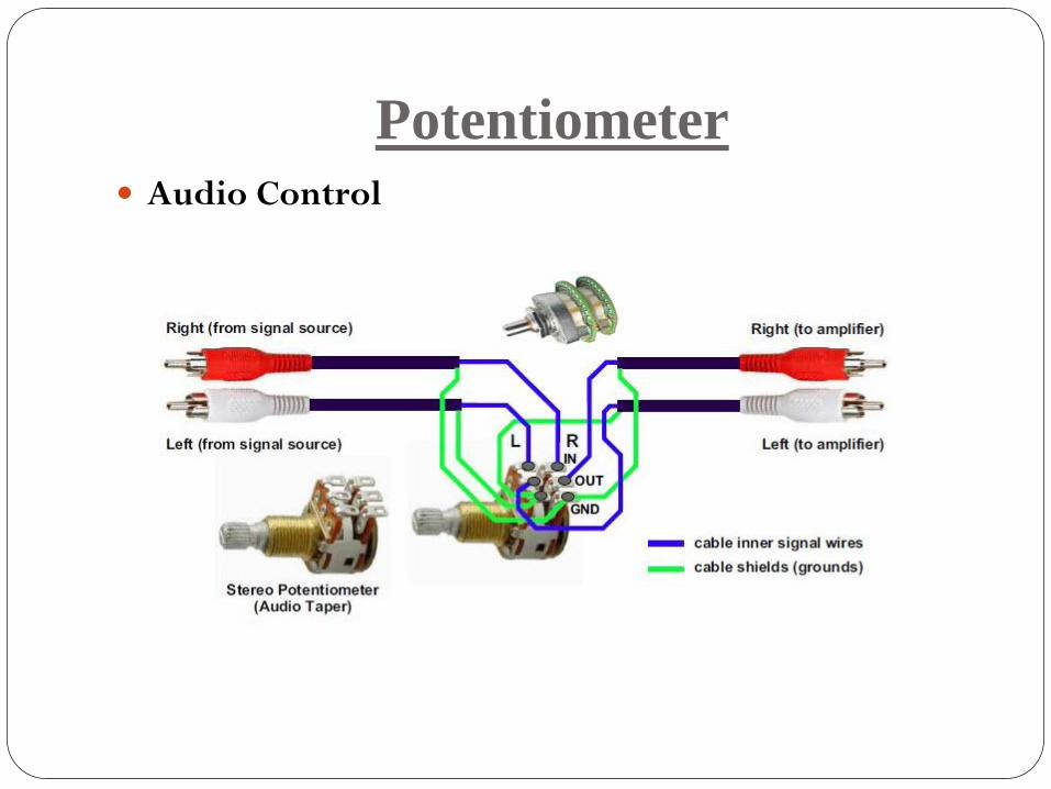
Audio Control
Potentiometer
Sliding potentiometers, one of the most common uses for
modern low-power potentiometers are as audio control
devices. Both sliding pots (faders) and rotary potentiometers
(knobs) are regularly used to frequency attenuation, adjust
loudness and for different characteristics of audio signals.
Potentiometer
Television
Potentiometers were used to control the picture brightness,
contrast, and colour response.
Transducers
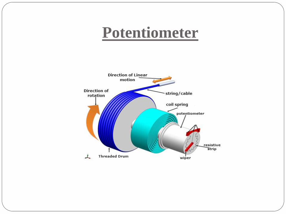
One of the most common application is measuring of
displacement. To measure the displacement of the body,
which is movable, is connected to the sliding element located
on the potentiometer. As the body moves, the position of the
slider also changes accordingly so the resistance between the
fixed point and the slider changes. Due to this the voltage
across these points also changes.
Potentiometer
Potentiometer as a Transducer X
The change in resistance or the voltage is proportional to the
change in the displacement of the body. Thus the voltage
change indicates the displacement of the body. This can be
used for the measurement of translational as well as well
rotational displacement. Since these potentiometers work on
the principle of resistance, they are also called as the resistive
potentiometers. For example, the shaft rotation might
represent an angle, and the voltage division ratio can be made
proportional to the cosine of the angle.
Potentiometer

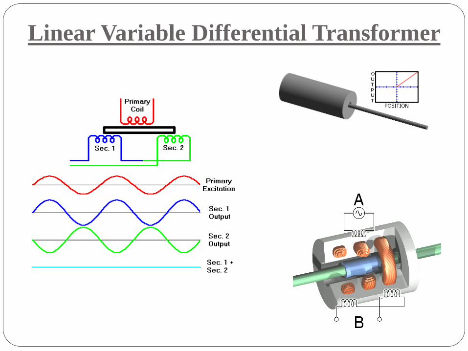
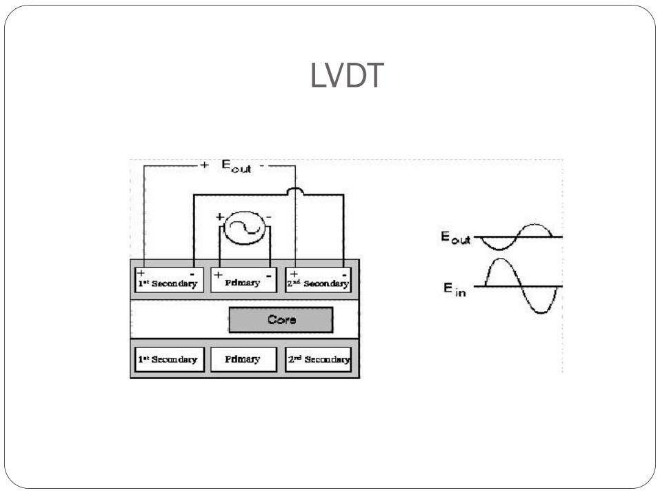
Linear Variable Differential Transformer
„LVDT‟ is a transducer for measuring linear displacement
It must be excited by an AC signal to induce AC response on
secondary.
The core position can be determined by measuring secondary
response.
Linear Variable Differential Transformer
LVDT
LVDT
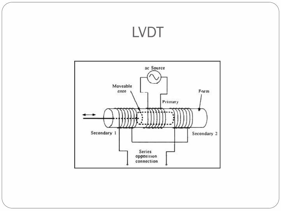
The above figure depicts a cross-sectional view of an LVDT.
The core causes the magnetic field generated by the primary
winding to be coupled to the secondaries.
When the core is centered perfectly between both
secondaries and the primary, as shown, the voltage induced in
each secondary is equal in amplitude and 180 deg out of
phase.
Thus the LVDT output (for the series-opposed connection
shown in this case) is zero because the voltages cancel each
other.
LVDT

LVDT
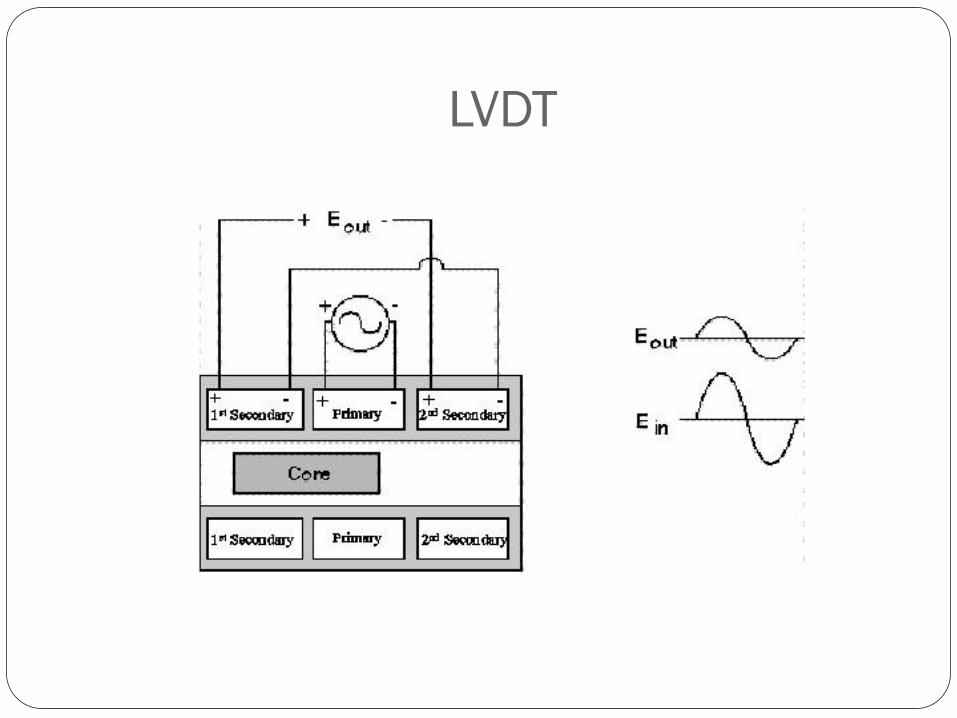
Displacing the core to the left (As per the above figure)
causes the first secondary to be more strongly coupled to the
primary than the second secondary.
The resulting higher voltage of the first secondary in relation
to the second secondary causes an output voltage that is in
phase with the primary voltage.
LVDT

LVDT
Likewise, displacing the core to the right causes the second
secondary to be more strongly coupled to the primary than
the first secondary.
The greater voltage of the second secondary causes an output
voltage to be out of phase with the primary voltage.
LVDT
CAPACITANCE SENSOR
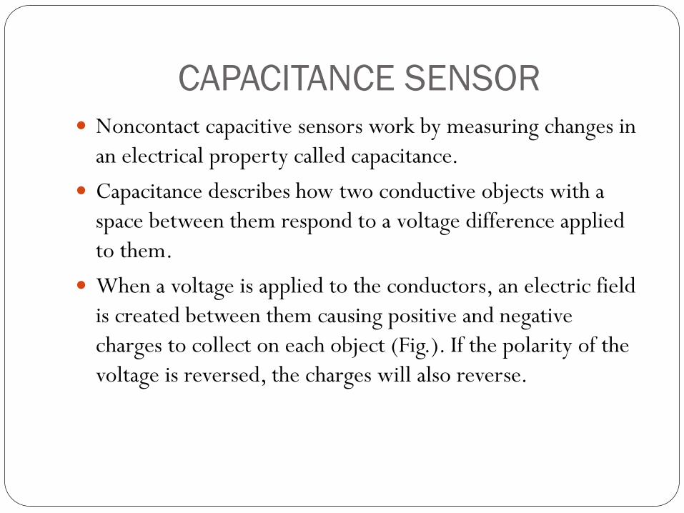
Noncontact capacitive sensors work by measuring changes in
an electrical property called capacitance.
Capacitance describes how two conductive objects with a
space between them respond to a voltage difference applied
to them.
When a voltage is applied to the conductors, an electric field
is created between them causing positive and negative
charges to collect on each object (Fig.). If the polarity of the
voltage is reversed, the charges will also reverse.
CAPACITANCE SENSOR
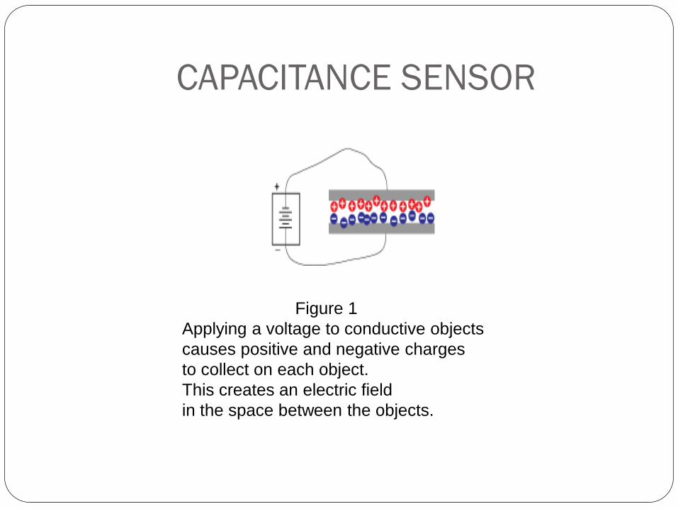
Figure 1
Applying a voltage to conductive objects
causes positive and negative charges
to collect on each object.
This creates an electric field
in the space between the objects.
CAPACITANCE SENSOR
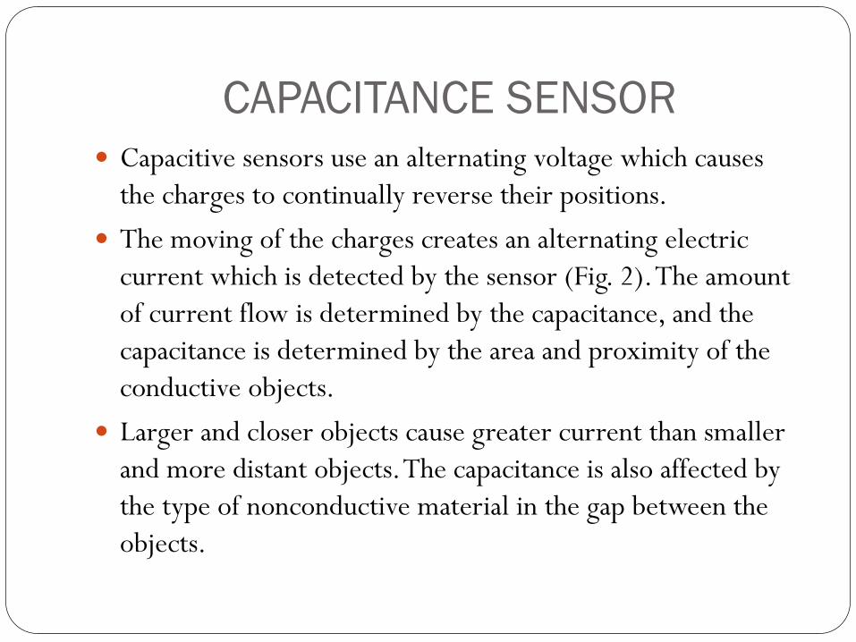
Capacitive sensors use an alternating voltage which causes
the charges to continually reverse their positions.
The moving of the charges creates an alternating electric
current which is detected by the sensor (Fig. 2). The amount
of current flow is determined by the capacitance, and the
capacitance is determined by the area and proximity of the
conductive objects.
Larger and closer objects cause greater current than smaller
and more distant objects. The capacitance is also affected by
the type of nonconductive material in the gap between the
objects.
CAPACITANCE SENSOR
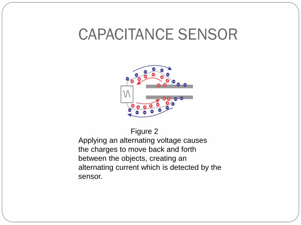
Figure 2
Applying an alternating voltage causes
the charges to move back and forth
between the objects, creating an
alternating current which is detected by the
sensor.
CAPACITANCE SENSOR
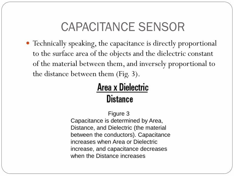
Technically speaking, the capacitance is directly proportional
to the surface area of the objects and the dielectric constant
of the material between them, and inversely proportional to
the distance between them (Fig. 3).
Figure 3
Capacitance is determined by Area,
Distance, and Dielectric (the material
between the conductors). Capacitance
increases when Area or Dielectric
increase, and capacitance decreases
when the Distance increases
CAPACITANCE SENSOR
Advantages:
There are some advantages of capacitive transducer which are
given below,
The sensitivity of capacitive transducer is high.
The capacitive transducer is useful for small system.
It has good frequency response.
It requires small power to operate.
The loading effect is less due to high input impedance.
Disadvantages:

CAPACITANCE SENSOR
Disadvantages:
There are some disadvantages of capacitive transducer which
are given below,
The capacitive transducers are temperature sensitive.
It gives non linear behavior.
The output impedance depends upon the frequency used.
The capacitance may get changed by dust particle and
moisture which produce error.
CAPACIVE SENSOR
Applications:
There are some important applications of capacitive
transducer which are given below,
The capacitive transducers are used to measure humidity in
gases.
It is used to measure volume, liquid level, density etc.
It is used for measurement of linear and angular
displacement.
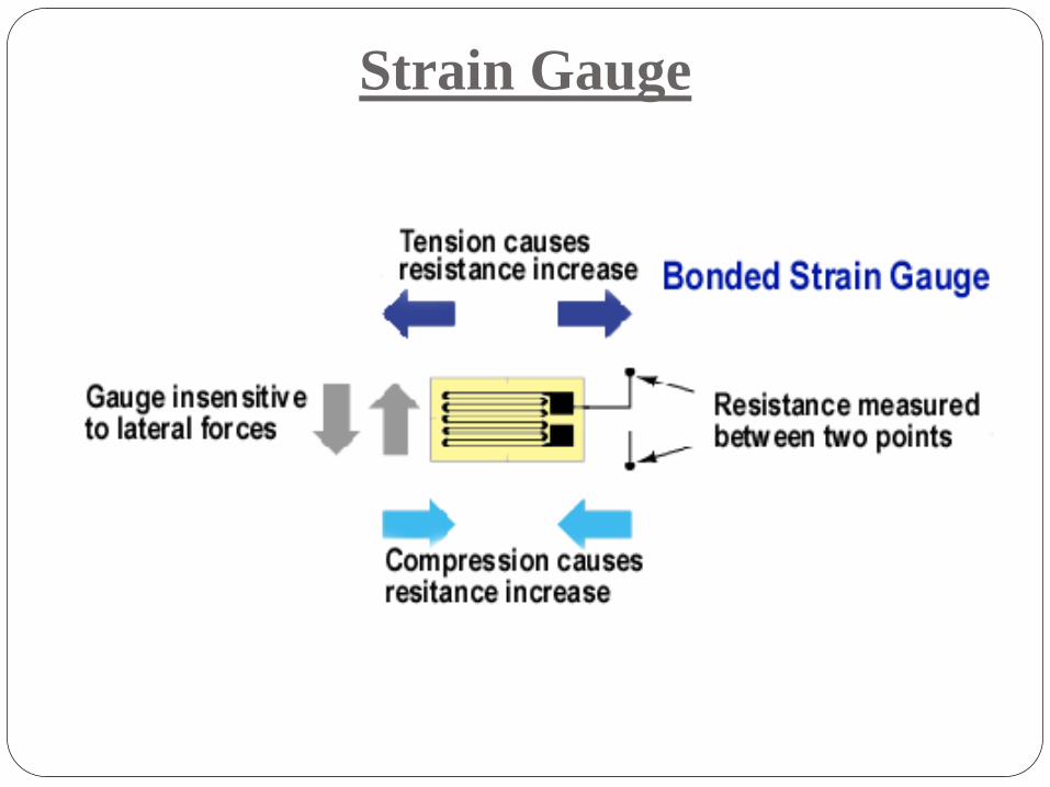
STRAIN GAUGES
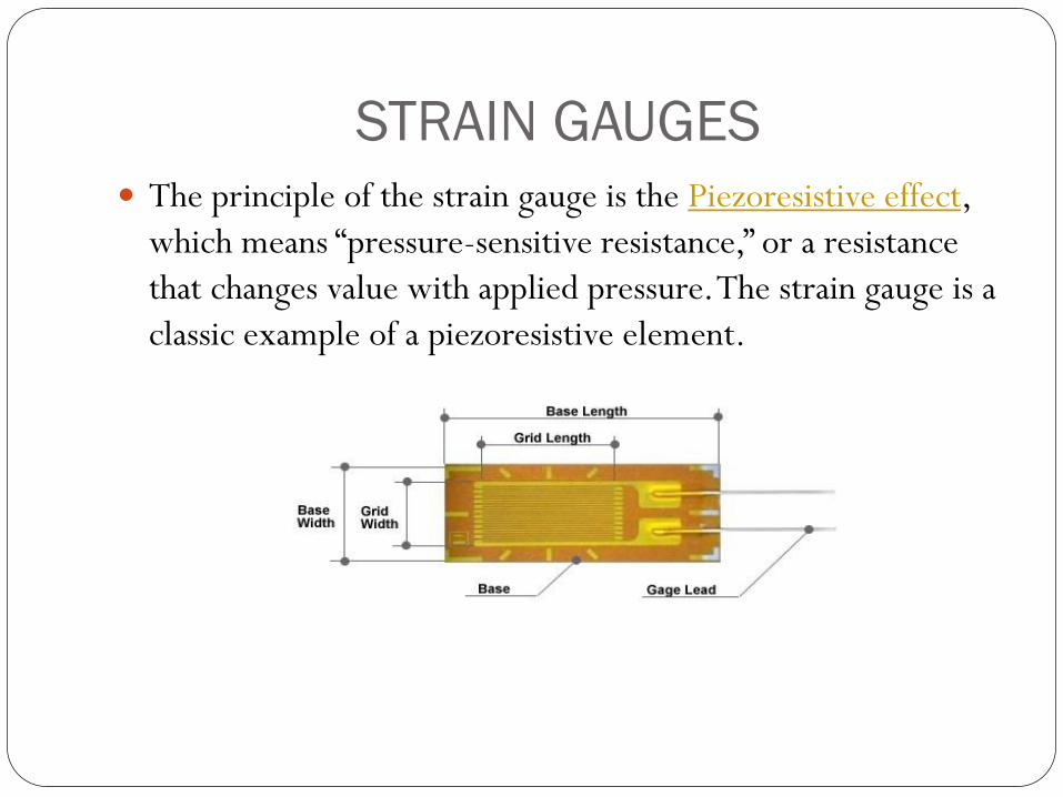
The principle of the strain gauge is the Piezoresistive effect,
which means “pressure-sensitive resistance,” or a resistance
that changes value with applied pressure. The strain gauge is a
classic example of a piezoresistive element.

STRAIN GAUGES Working
Strain gauges in their infancy were metal wires supported by
a frame.
Advances in the technology of bonding materials mean that
the wire can adhere directly to the strained surface. Since the
measurement of strain involves the deformation of metal, the
strain material need not be limited to being a wire.
As such, further developments also involve metal foil gauges.
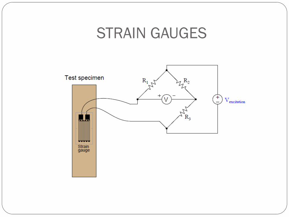
Bonded strain gauges are the more commonly used type.
There is the Wheatstone bridge arrangement where the
change in pressure is detected as a change in the measured
voltage:
STRAIN GAUGES
STRAIN GAUGES
The change in the resistance of the strain gauge breaks the
balance of the Wheatstone’s bridge and change the voltage V.
The voltage V is proportional to the pressure change in the
strain gauge.
Applications:
Residual stress
Vibration measurement
Torque measurement
Strain measurement
Compression and tension measurement
Encoders
Digital Optical Encoders
Absolute Digital Optical Encoders
Incremental Digital Optical Encoders

EDDY CURRENT SENSOR
Eddy-Current sensors operate with magnetic fields. The driver creates
an alternating current in the sensing coil in the end of the probe. This
creates an alternating magnetic field with induces small currents in the
target material; these currents are called eddy currents.
EDDY CURRENT SENSOR
The eddy currents create an opposing magnetic field which
resists the field being generated by the probe coil.
The interaction of the magnetic fields is dependent on the
distance between the probe and the target.
As the distance changes, the electronics sense the change in
the field interaction and produce a voltage output which is
proportional to the change in distance between the probe and
target.

EDDY CURRENT SENSOR
Applications
Eddy-Current sensors are useful in any application requiring
the measurement or monitoring of the position of a
conductive target, especially in a dirty environment.
HALL EFFECT SENSOR
HALL EFFECT SENSOR
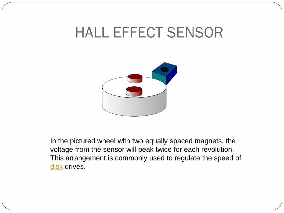
In the pictured wheel with two equally spaced magnets, the
voltage from the sensor will peak twice for each revolution.
This arrangement is commonly used to regulate the speed of
disk drives.
HALL EFFECT SENSOR
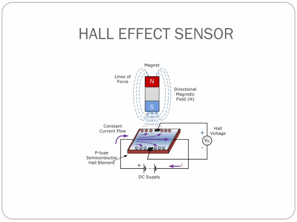
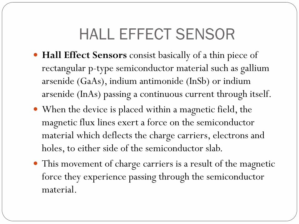
Hall Effect Sensors consist basically of a thin piece of
rectangular p-type semiconductor material such as gallium
arsenide (GaAs), indium antimonide (InSb) or indium
arsenide (InAs) passing a continuous current through itself.
When the device is placed within a magnetic field, the
magnetic flux lines exert a force on the semiconductor
material which deflects the charge carriers, electrons and
holes, to either side of the semiconductor slab.
This movement of charge carriers is a result of the magnetic
force they experience passing through the semiconductor
material.
HALL EFFECT SENSOR
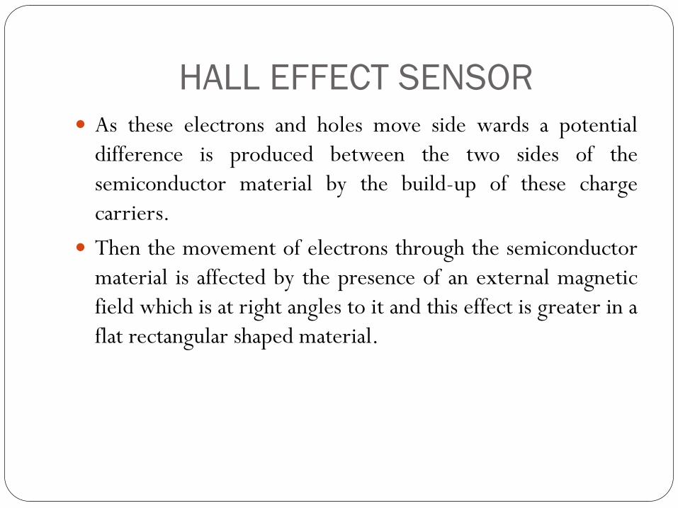
As these electrons and holes move side wards a potential
difference is produced between the two sides of the
semiconductor material by the build-up of these charge
carriers.
Then the movement of electrons through the semiconductor
material is affected by the presence of an external magnetic
field which is at right angles to it and this effect is greater in a
flat rectangular shaped material.
HALL EFFECT SENSOR
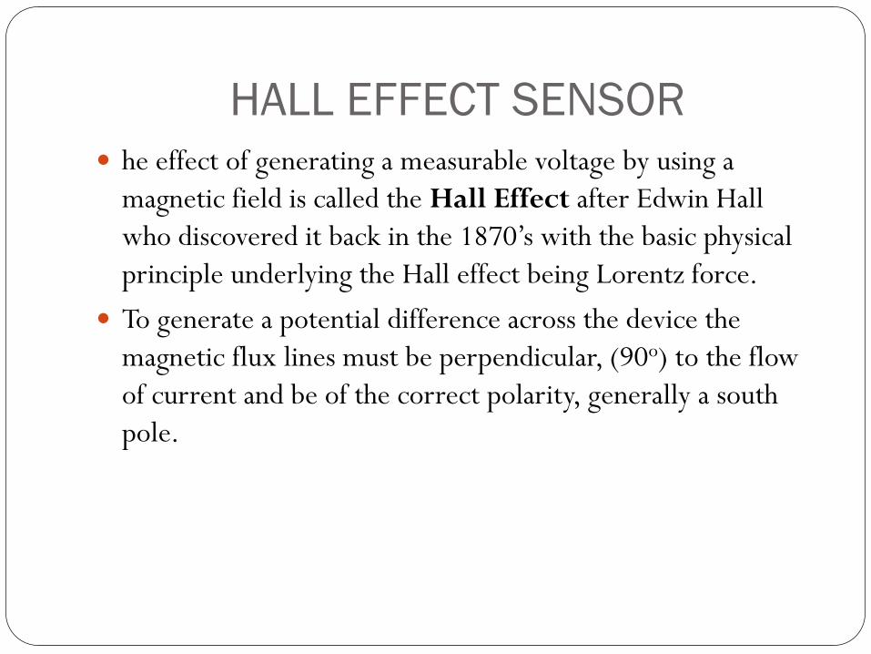
he effect of generating a measurable voltage by using a
magnetic field is called the Hall Effect after Edwin Hall
who discovered it back in the 1870’s with the basic physical
principle underlying the Hall effect being Lorentz force.
To generate a potential difference across the device the
magnetic flux lines must be perpendicular, (90o) to the flow
of current and be of the correct polarity, generally a south
pole.

HALL EFFECT SENSOR
The Hall effect provides information regarding the type of
magnetic pole and magnitude of the magnetic field. For
example, a south pole would cause the device to produce a
voltage output while a north pole would have no effect.
Generally, Hall Effect sensors and switches are designed to be
in the “OFF”, (open circuit condition) when there is no
magnetic field present. They only turn “ON”, (closed circuit
condition) when subjected to a magnetic field of sufficient
strength and polarity.
HALL EFFECT SENSOR
Applications
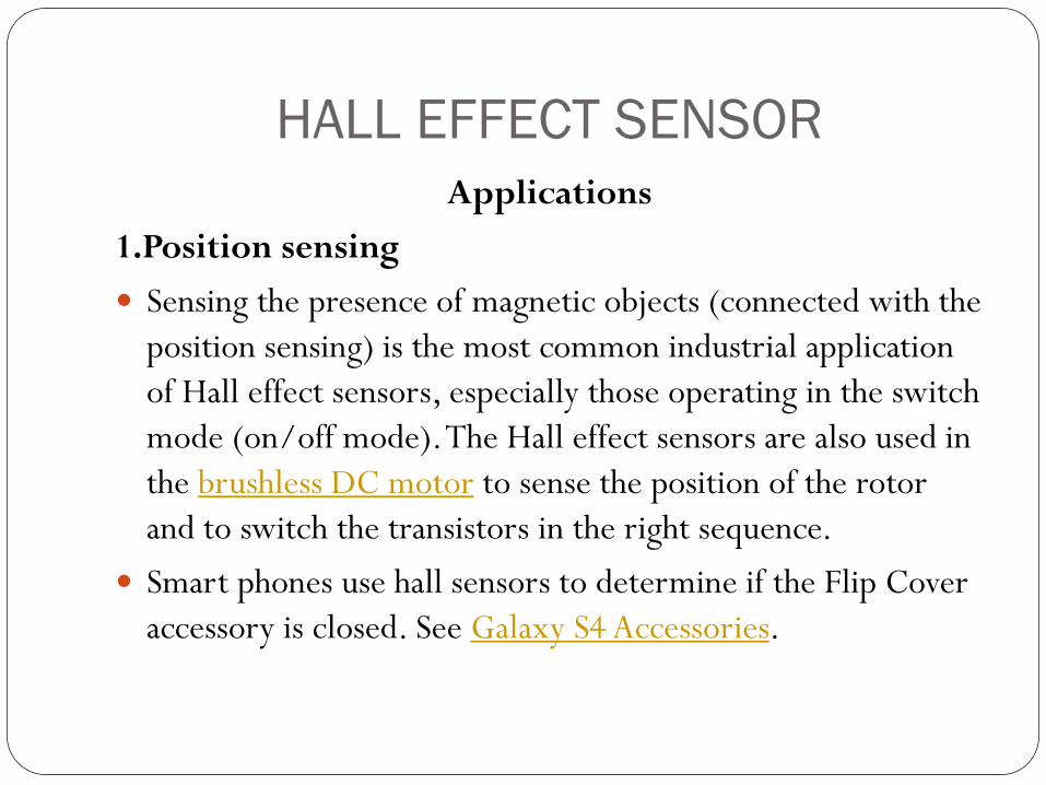
1.Position sensing
Sensing the presence of magnetic objects (connected with the
position sensing) is the most common industrial application
of Hall effect sensors, especially those operating in the switch
mode (on/off mode). The Hall effect sensors are also used in
the brushless DC motor to sense the position of the rotor
and to switch the transistors in the right sequence.
Smart phones use hall sensors to determine if the Flip Cover
accessory is closed. See Galaxy S4 Accessories.
HALL EFFECT SENSOR
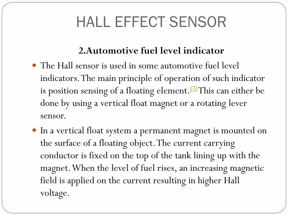
2.Automotive fuel level indicator
The Hall sensor is used in some automotive fuel level
indicators. The main principle of operation of such indicator
is position sensing of a floating element.[7] This can either be
done by using a vertical float magnet or a rotating lever
sensor.
In a vertical float system a permanent magnet is mounted on
the surface of a floating object. The current carrying
conductor is fixed on the top of the tank lining up with the
magnet. When the level of fuel rises, an increasing magnetic
field is applied on the current resulting in higher Hall
voltage.
HALL EFFECT SENSOR
As the fuel level decreases, the Hall voltage will also
decrease. The fuel level is indicated and displayed by proper
signal condition of Hall voltage.
In a rotating lever sensor a diametrically magnetized ring
magnet rotates about a linear hall sensor. The sensor only
measures the perpendicular (vertical) component of the
field. The strength of the field measured correlates directly to
the angle of the lever and thus the level of the fuel tank.
HALL EFFECT SENSOR
3.Direct current transformers Hall effect sensors may be utilized for contactless
measurements of DC current in current transformers. In such a
case the Hall effect sensor is mounted in the gap in magnetic
core around the current conductor.[6] As a result, the DC
magnetic flux can be measured, and the DC current in the
conductor can be calculated

Temperature Sensor
What is a Temperature Sensor?
A simple temperature sensor is a device, to measure the
temperature through an electrical signal it requires a
thermocouple or RTD (Resistance Temperature Detectors).
The thermocouple is prepared by two dissimilar metals
which generate the electrical voltage indirectly proportional
to change the temperature.
The RTD is a variable resistor, it will change the electrical
resistance indirectly proportional to changes in the
temperature in a precise, and nearly linear manner.
Temperature Sensor
Thermocouple Sensor
The thermocouple sensor measures the popular thermals,
which are composed of the two different metal alloy wires.
By combining the two different metals will generates the
strong voltage which is the same capacity as a temperature.
In general, the thermocouple gives the vast measurement
ranges and they are worked by using the Seebeck effect.
The Seebeck effect invested for changing the temperature in
the electrical circuit. The sensor reads the temperature by
taking the measurement of voltage output.

Temperature Sensor
Thermocouple Sensor
Temperature Sensor
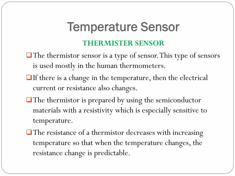
THERMISTER SENSOR
The thermistor sensor is a type of sensor. This type of sensors
is used mostly in the human thermometers.
If there is a change in the temperature, then the electrical
current or resistance also changes.
The thermistor is prepared by using the semiconductor
materials with a resistivity which is especially sensitive to
temperature.
The resistance of a thermistor decreases with increasing
temperature so that when the temperature changes, the
resistance change is predictable.

Temperature Sensor
THERMISTER SENSOR
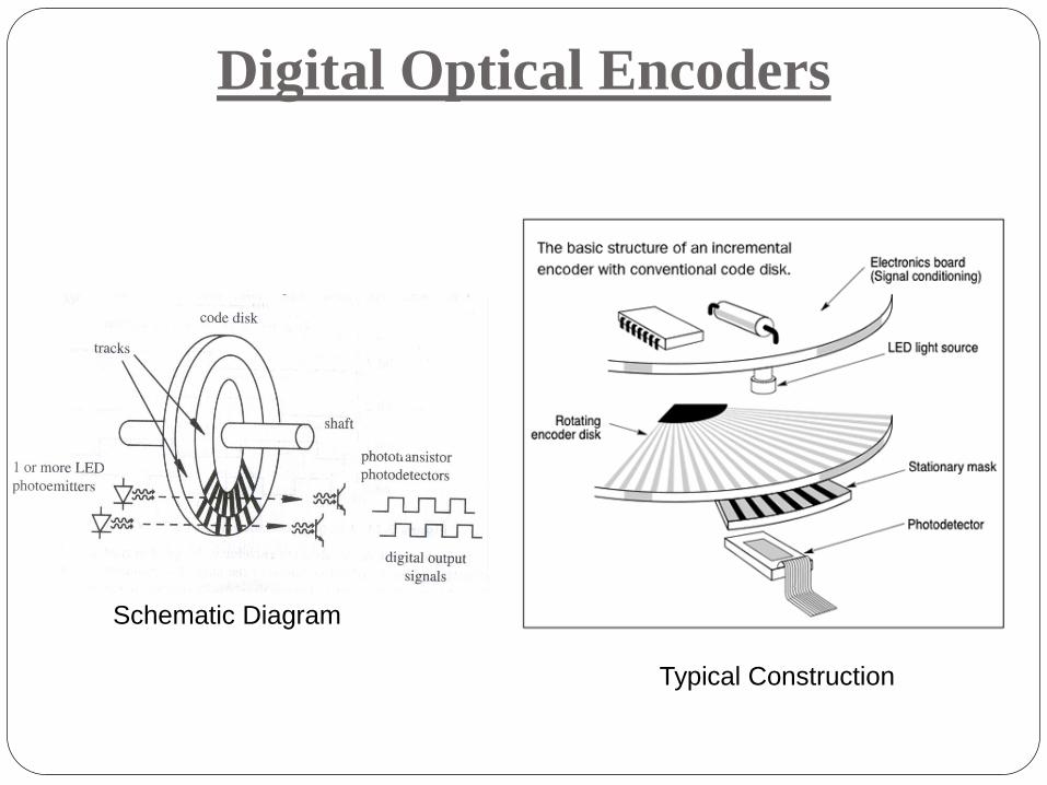
Digital Optical Encoders
Schematic Diagram
Typical Construction

Simple Rotary Encoder
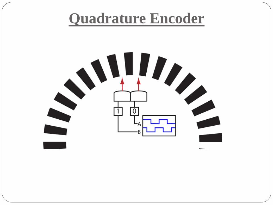
Quadrature Encoder

Binary Encoder

Grey Code Encoder
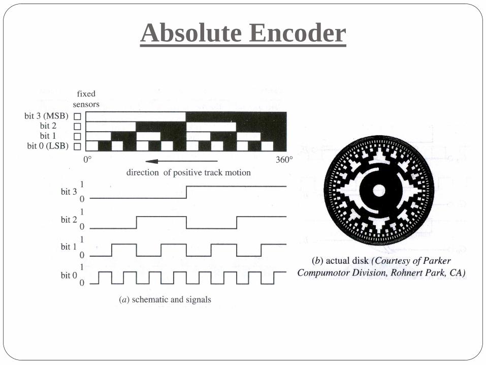
Absolute Encoder

Absolute Encoder (Gray Code)

Incremental Encoder

Proximity sensors
Proximity sensors:
Optical
Inductive
Capacitive

Proximity sensors

Application of Proximity sensors

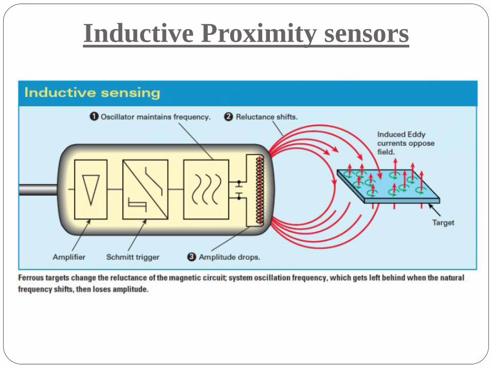
Inductive Proximity sensors
• Detects metal object
• Uses an electro-magnetic field to detect a conductive target
• Sensing coil in the end of the sensor probe
• When excited creates an alternating magnetic field which induces small
amounts of eddy current in the target object
• Eddy currents create an opposing magnetic field which resists the field
being generated by the sensor probe coil.
• The interaction of the magnetic fields is dependent on the distance
between the sensor probe and the target.
• Comparatively inexpensive but conducting targets sensing
Inductive Proximity sensors
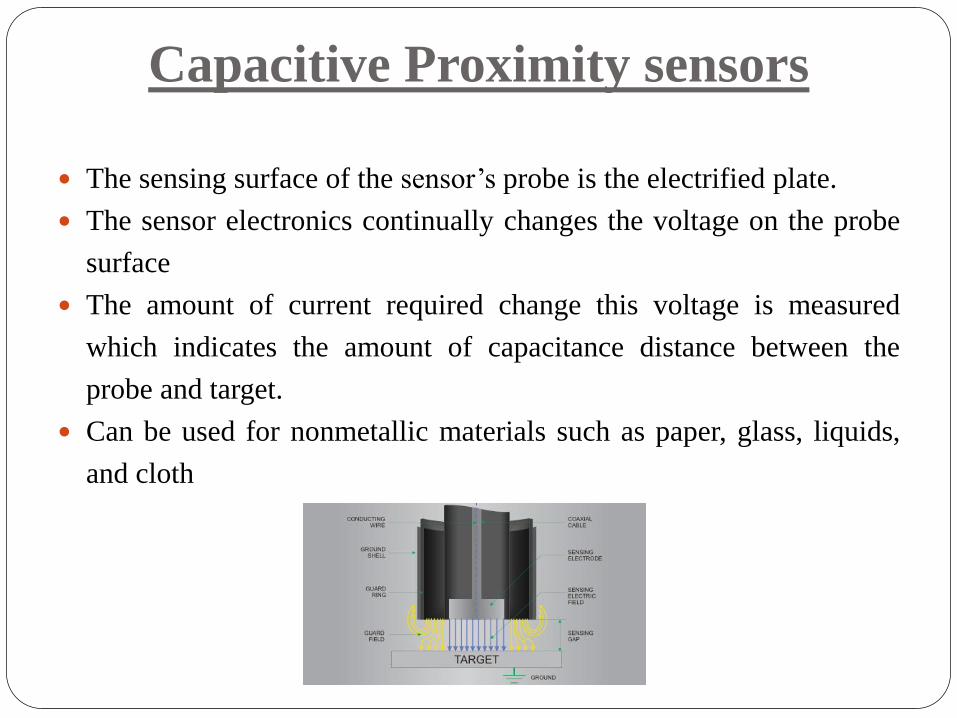
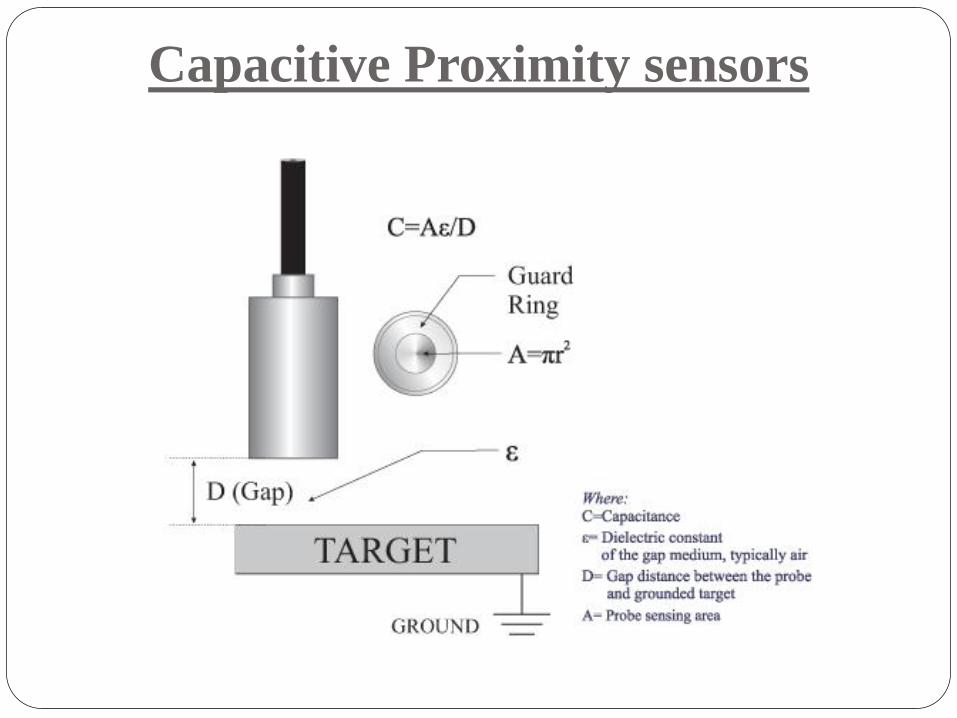
Capacitive Proximity sensors
The sensing surface of the sensor‟s probe is the electrified plate.
The sensor electronics continually changes the voltage on the probe
surface
The amount of current required change this voltage is measured
which indicates the amount of capacitance distance between the
probe and target.
Can be used for nonmetallic materials such as paper, glass, liquids,
and cloth
Capacitive Proximity sensors

• Motion Sensors:
• Variable Reluctance
• Temperature Sensor:
• RTD
• Thermocouples

Variable Reluctance sensor
A magnet in the sensor creates a
magnetic field
As a ferrous object moves by the
sensor, the resulting change in the
magnetic flux induces an emf in
the pickup coil
Variable Reluctance sensor
• Used to measure speed and/or position of a moving metallic
object
• Sense the change of magnetic reluctance (analogous to
electrical resistance) near the sensing element
• Require conditioning circuitry to yield a useful signal (e.g.
LM1815 from National Semi.)

Temperature measurement
• EMF based
• Thermocouple
• Resistance based
• Resistance Temperature Detectors (RTD)

Thermocouples
If two different metals „A‟ and „B‟ are connected as in Figure, with a junction and a voltmeter, then if the junction is heated the meter should show a voltage.
This is known as the Seebeck effect.

Construction of Thermocouples
At the tip of a grounded junction probe, the thermocouple wires are physically attached to the inside of the probe wall. This results in good heat transfer from the outside, through the probe wall to the thermocouple junction.
In an ungrounded probe, the thermocouple junction is detached from the probe wall. Response time is slower than the grounded style, but the ungrounded offers electrical isolation.
The thermocouple in the exposed junction style protrudes out of the tip of the sheath and is exposed to the surrounding environment. This type offers the best response time, but is limited in use to dry, non-corrosive and non-pressurized applications.

Types of thermocouples
Sr.
No
Type Thermocouple Material Sensitivit
y in
(µV/oC)
Useful
temperature
range
1 T Copper-Constantan 20 – 60 -180 to +400
2 J Iron-Constantan 45 – 55 -180 to +850
3 K Chromel-Alumel 40 – 55 -200 to +1300
4 E Chromel-Constantan 55 – 80 -180 to +850
5 S Platinum-Platinum/10% Rhodium 5 – 12 0 to +1400
6 R Platinum-Platinum/13% Rhodium 5 – 12 0 to +1600
7 B Platinum/ 30% Rhodium-Platinum/6% Rhodium 5 – 12 +100 to +1800
8 W5 Tungsten/5% Rhenium-Tungsten/20% Rhenium 5 – 12 0 to +3000
Constantan = copper/nickel; Chromel = nickel/chromium; Alumenl = nickel/aluminium
Selection of Thermocouples
The following criteria are used in selecting a thermocouple:
Temperature range
Chemical resistance of the thermocouple or sheath material
Abrasion and vibration resistance
Installation requirements (may need to be compatible with
existing equipment; existing holes may determine probe
diameter)

Resistance Temperature Detector
(RTD)
Uses the phenomenon that the resistance of a metal changes with
temperature.
Are linear over a wide range and most stable.

Advantages of platinum as RTD
The temperature-resistance characteristics of pure platinum
are stable over a wide range of temperatures.
It has high resistance to chemical attack and contamination
It forms the most easily reproducible type of temperature
transducer with a high degree of accuracy .
It can have accuracy ± 0.01 oC up to 500 oC and ± 0.1 oC
up to 1200 oC.
Limitations of RTD
These are resistive devices, and accordingly they function by
passing a current through a sensor.
Even though only a very small current is generally employed,
it creates a certain amount of heat and thus can throw off the
temperature reading.
This self heating in resistive sensors can be significant when
dealing with a still fluid (i.e., one that is neither flowing nor
agitated), because there is less carry-off of the heat
generated.
This problem does not arise with thermocouples, which are
essentially zero-current devices.
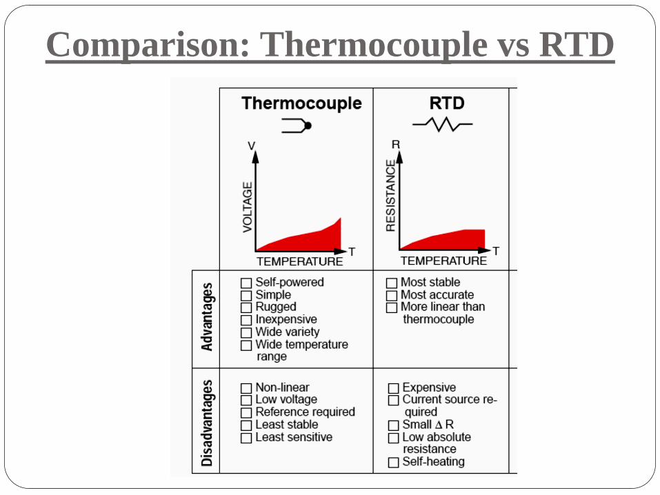
Comparison: Thermocouple vs RTD
Force/Pressure Sensor
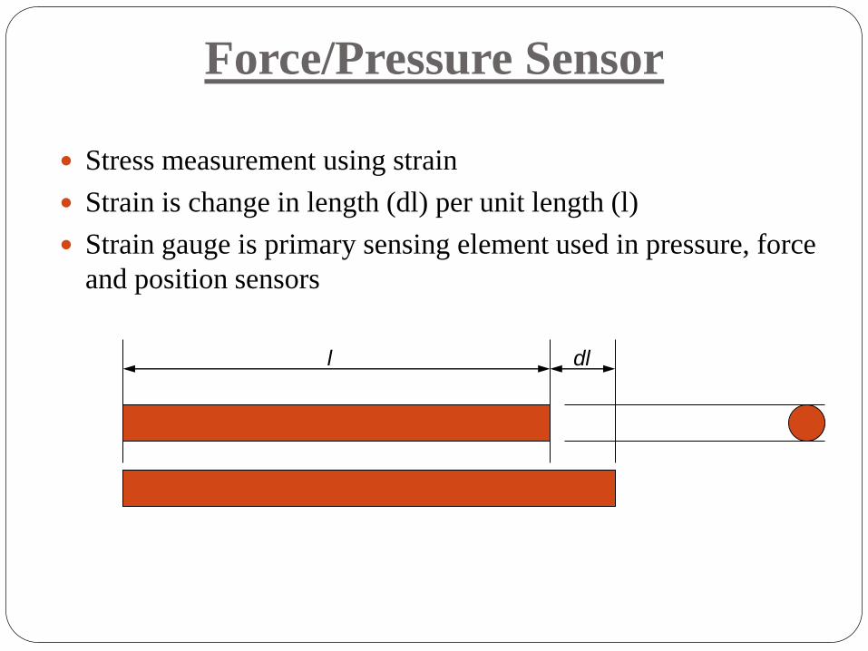
Stress measurement using strain
Strain is change in length (dl) per unit length (l)
Strain gauge is primary sensing element used in pressure, force
and position sensors
l dl

Strain Gauge
Based on the variation of resistance of a conductor
or semiconductor when subjected to a mechanical
stress.
The electric resistance of a wire having length l,
cross section A, and resistivity ρ is:
When the wire is stressed longitudinally, R
undergoes a change.
Passing small amount of current through such wire
will, thus, help measure voltage change.
The sensing element of the strain gage is made of
copper-nickel alloy foil. The alloy foil has a rate of
resistance change proportional to strain with a
certain constant.
A
lR
Strain Gauge
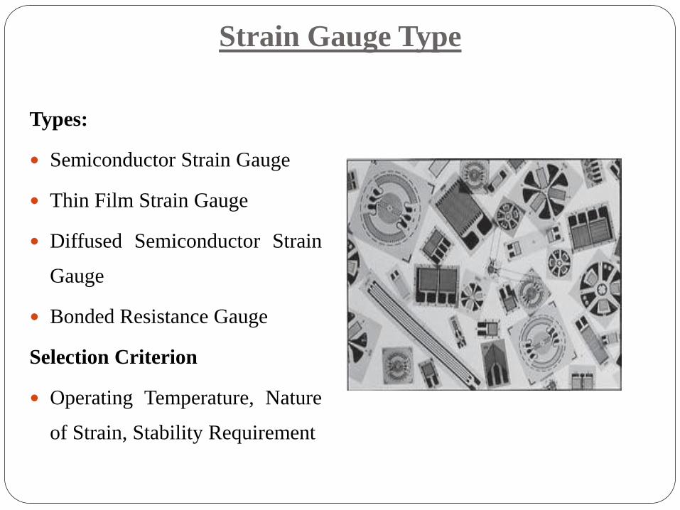
Strain Gauge Type
Types:
Semiconductor Strain Gauge
Thin Film Strain Gauge
Diffused Semiconductor Strain
Gauge
Bonded Resistance Gauge
Selection Criterion
Operating Temperature, Nature
of Strain, Stability Requirement
Strain Gauge
To measure the strain requires accurate measurement of very
small changes in resistance.
For example, suppose a test specimen undergoes a strain of
500 x10-6.
A strain gauge with a gauge factor of 2 will exhibit a change
in electrical resistance of only 2x(500 x 10-6).
For a 120 Ω gauge, this is a change of only 0.12 Ω.
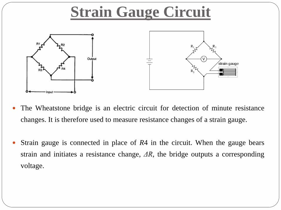
Strain Gauge Circuit
The Wheatstone bridge is an electric circuit for detection of minute resistance
changes. It is therefore used to measure resistance changes of a strain gauge.
Strain gauge is connected in place of R4 in the circuit. When the gauge bears
strain and initiates a resistance change, ΔR, the bridge outputs a corresponding
voltage.

• With no force applied to the test specimen, both strain gauges have
equal resistance and the bridge circuit is balanced.
• However, when a downward force is applied to the free end of the
specimen, it will bend downward, stretching gauge #1 and
compressing gauge #2

Strain Gauge Circuit
l
lRR
GF
GFV
V
GFV
V
GFV
V
input
output
input
output
input
output
:eqns aboveIn
:Bridge Full
2
1 :Bridge Half
4
1 :BridgeQuarter
Effect of Temperature on Output of Gauge
Ideally, we would like the resistance of the strain gauge to change only in response to applied strain.
However, strain gauge material, as well as the specimen material to which the gauge is applied, will also respond to changes in temperature.
Strain gauge manufacturers attempt to minimize sensitivity to temperature by processing the gauge material to compensate for the thermal expansion of the specimen material; compensated gauges reduce the thermal sensitivity, they do not totally remove it.
Temperature compensation
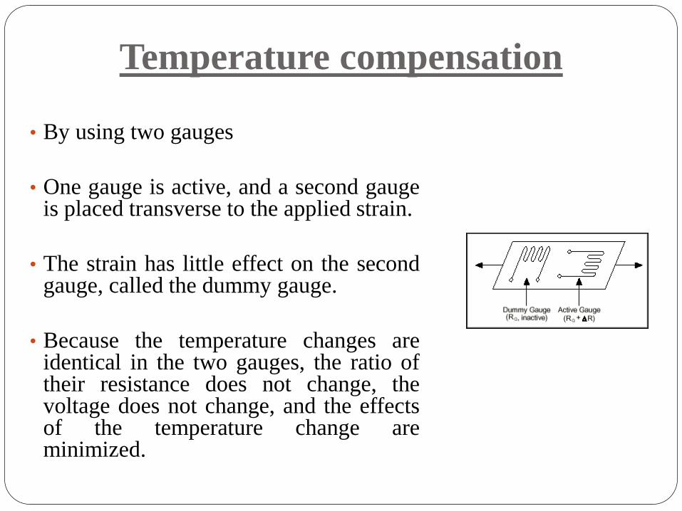
• By using two gauges
• One gauge is active, and a second gauge is placed transverse to the applied strain.
• The strain has little effect on the second gauge, called the dummy gauge.
• Because the temperature changes are identical in the two gauges, the ratio of their resistance does not change, the voltage does not change, and the effects of the temperature change are minimized.

Electromagnetic Flow sensor
Magnetic flow meters operate based upon Faraday's Law of electromagnetic induction, which states that a voltage will be induced in a conductor moving through a magnetic field.
Faraday's Law: E=kBDV
The magnitude of the induced voltage E is directly proportional to the velocity of the conductor V, conductor width D, and the strength of the magnetic field B.
Magnetic field coils are placed on opposite sides a pipe to generate a magnetic field.
Electromagnetic Flow sensor
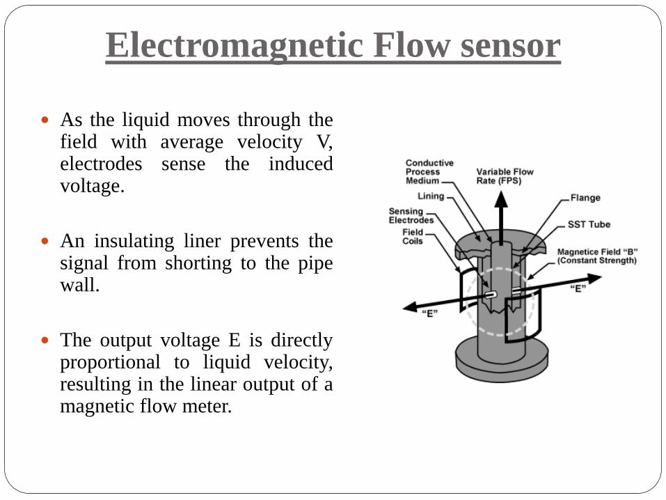
As the liquid moves through the field with average velocity V, electrodes sense the induced voltage.
An insulating liner prevents the signal from shorting to the pipe wall.
The output voltage E is directly proportional to liquid velocity, resulting in the linear output of a magnetic flow meter.

Stepper Motor
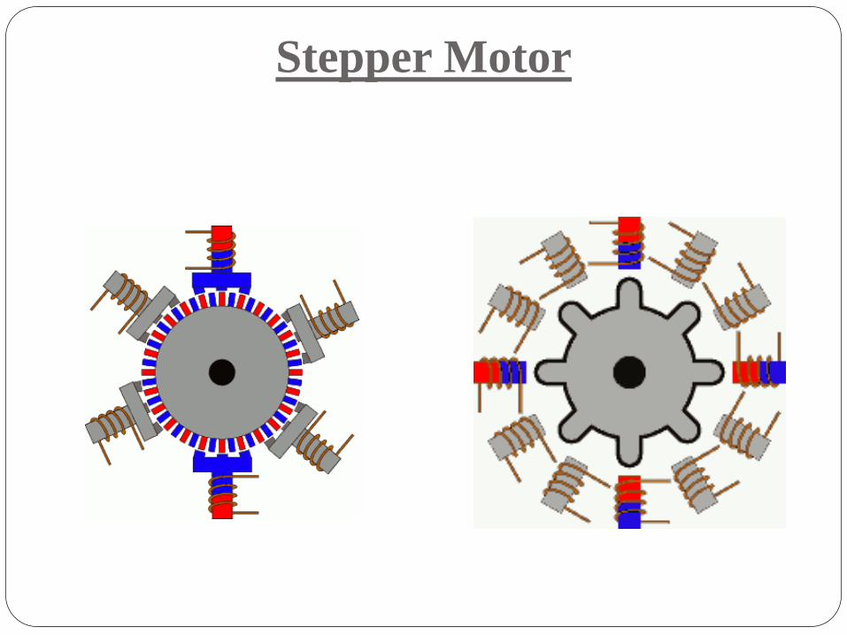
Discrete Positioning device
Moves one step at a time for each input
Appropriate excitation in winding/s, makes the rotor attract
towards the stator
Stepper Motor
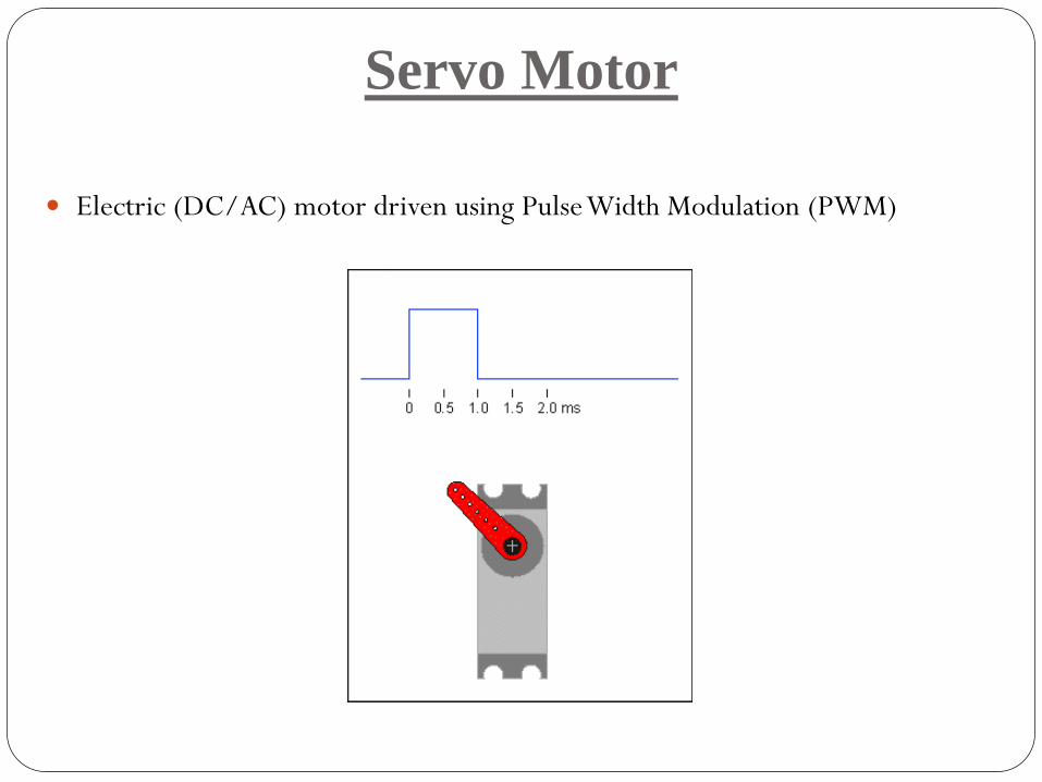
Servo Motor
Electric (DC/AC) motor driven using Pulse Width Modulation (PWM)
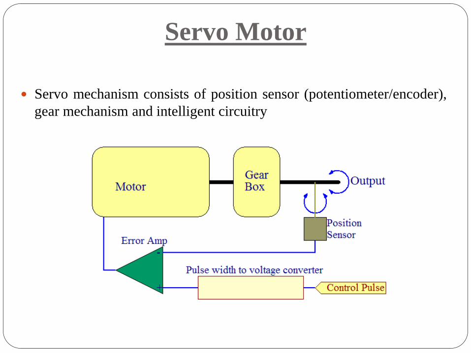
Servo mechanism consists of position sensor (potentiometer/encoder),
gear mechanism and intelligent circuitry
Servo Motor
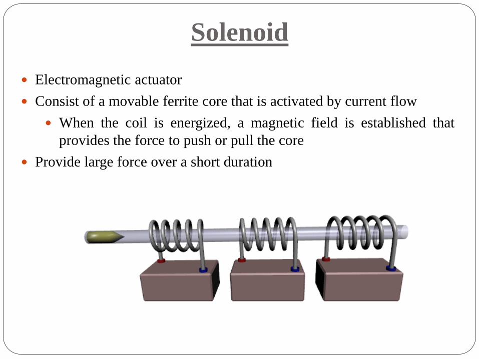
Solenoid
Electromagnetic actuator
Consist of a movable ferrite core that is activated by current flow
When the coil is energized, a magnetic field is established that
provides the force to push or pull the core
Provide large force over a short duration