MFH-RAPTOR High Feed Milling - KYOCERA Precision Tools, Inc. · High Feed Milling for Small...
28
Reduce Cycle Time During Roughing Applications Multi-Functional for Various Applications MFH Mini / Micro High Feed Mills for Small Machining Centers High Feed Milling Cutters Stable Machining with Greater Chatter Resistance MFH -RAPT R Ø0.375"~Ø0.625" | Ø8mm~Ø16mm Ø0.625"~Ø2.000" | Ø16mm~Ø50mm Ø1.000"~Ø6.000" | Ø25mm~Ø160mm
Transcript of MFH-RAPTOR High Feed Milling - KYOCERA Precision Tools, Inc. · High Feed Milling for Small...

Reduce Cycle Time During Roughing Applications
Multi-Functional for Various Applications
MFH Mini / Micro High Feed Mills for Small Machining Centers
High Feed Milling Cutters
Stable Machining with Greater Chatter Resistance
MFH-RAPT R
Ø0.375"~Ø0.625" | Ø8mm~Ø16mm Ø0.625"~Ø2.000" | Ø16mm~Ø50mm Ø1.000"~Ø6.000" | Ø25mm~Ø160mm

2
Convex Cutting Edge Design Reduces Chatter for High-Efficiency Rough MachiningLarge Tooling Lineup to Cover a Wide Application Range for Multiple Metalworking Processes
MFH Series
For Using MFH:GM chipbreaker is available for all the above applications. LD and FL chipbreakers are not available for helical milling, plunging and contouring of rising wall. (Refer to Page 11)
M iCRoMFH-RAPT R
Cutt
ing
Forc
e (N
)
Cutt
ing
Forc
e (N
)
Cutting Time (msec) (msec=1/1,000sec) Cutting Time (msec) (msec=1/1,000sec)
600
1,200
1,500
900
300
600
1,200
1,500
900
300
0 01 2 3 4 5 6 1 2 3 4 5 6
Competitor A: Heavy ImpactMFH Mini: Light Impact
Cutting Conditions: Cutter Dia. DCX = Ø0.625”, Vc = 490 sfm, fz = 0.039 ipt, D.O.C. × ae = 0.020” × 0.315”, Dry Workpiece : 1049 Structural Steel
Convex Edge Design
Cutting Force and Vibration when Approaching the Workpiece (D.O.C. = Half of Cutter Diameter)
Cutter Diameter Ø1.000"~Ø6.000" Cutter Diameter Ø25mm~Ø160mm
3 Different Insert Designs Offer a Variety of Machining Options
Cutter Diameter Ø0.375"~Ø0.625" Cutter Diameter Ø8mm~Ø16mm
Can Replace Solid End Mills to Reduce Machining Costs
Cutter Diameter Ø0.625"~Ø2.000" Cutter Diameter Ø16mm~Ø50mm
Economical Inserts with 4 Cutting Edges
MFH MiniLOGU Insert
MFH MicroLPGT Insert
MFHLOMU Insert
Face Milling & Shouldering
Helical Milling ContouringSlotting PocketingRamping
Reduces Cutting Forces at Initial Impact with a Convex Helical Edge Design
Reduced Chattering with Convex Cutting Edge Design1
Wide Application Range for Multiple Metalworking Processes2
MFH-RAPT RM iN iMFH-RAPT R
3
Convex Cutting Edge Design Reduces Chatter for High-Efficiency Rough MachiningLarge Tooling Lineup to Cover a Wide Application Range for Multiple Metalworking Processes
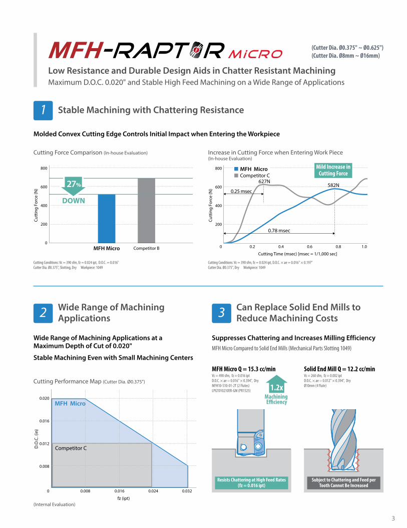
Low Resistance and Durable Design Aids in Chatter Resistant MachiningMaximum D.O.C. 0.020" and Stable High Feed Machining on a Wide Range of Applications
M iCRoMFH-RAPT R
Molded Convex Cutting Edge Controls Initial Impact when Entering the Workpiece
Cutting Force Comparison (In-house Evaluation) Increase in Cutting Force when Entering Work Piece (In-house Evaluation)
Cutting Conditions: Vc = 390 sfm, fz = 0.024 ipt, D.O.C. = 0.016"Cutter Dia. Ø0.375", Slotting, Dry Workpiece: 1049
Cutting Conditions: Vc = 390 sfm, fz = 0.024 ipt, D.O.C. × ae = 0.016" × 0.197"Cutter Dia. Ø0.375", Dry Workpiece: 1049
Stable Machining with Chattering Resistance1
Wide Range of Machining Applications at a Maximum Depth of Cut of 0.020"
Stable Machining Even with Small Machining Centers
Cutting Performance Map (Cutter Dia. Ø0.375")
(Internal Evaluation)
Wide Range of Machining Applications2
MFH Micro Competitor B
800
600
400
200
0
DOWN
27%
DOWN
Cutt
ing
Forc
e (N
)
800
600
400
200
0.2
0.78 msec
0.25 msec
0.4 0.6 0.8 1.0
Cutt
ing
Forc
e (N
)
Cutting Time (msec) [msec = 1/1,000 sec]
582N
0
MFH MicroCompetitor C
627N
0.020
0.016
0.012
0.008
0.008 0.016 0.024 0.032
fz (ipt)
D.O
.C. (
in)
Competitor C
MFH Micro
0
Mild Increase in Cutting Force
Suppresses Chattering and Increases Milling EfficiencyMFH Micro Compared to Solid End Mills (Mechanical Parts Slotting 1049)
Can Replace Solid End Mills toReduce Machining Costs3
MFH Micro Q = 15.3 cc/minVc = 490 sfm, fz = 0.016 ipt D.O.C. × ae = 0.016" × 0.394", DryMFH10-S10-01-2T (2 Flutes)LPGT010210ER-GM (PR1525)
Resists Chattering at High Feed Rates(fz = 0.016 ipt)
Solid End Mill Q = 12.2 cc/minVc = 260 sfm, fz = 0.002 ipt D.O.C. × ae = 0.012" × 0.394", DryØ10mm (4 Flute)
Subject to Chattering and Feed per Tooth Cannot Be Increased
1.2xMachining E�ciency
(Cutter Dia. Ø0.375" ~ Ø0.625")(Cutter Dia. Ø8mm ~ Ø16mm)
4
Cutter Dia. 1.000" Type
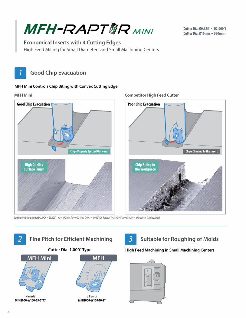
Cutting Conditions: Cutter Dia. DCX = Ø0.625" , Vc = 490 sfm, fz = 0.024 ipt, D.O.C. = 0.020" (20 Passes): Total 0.394" × 0.630", Dry Workpiece: Stainless Steel
MFH Mini Competitor High Feed Cutter
Poor Chip Evacuation
MFH Mini
5 InsertsMFH1000-W100-03-5T47
MFH
2 InsertsMFH1000-W100-10-2T
Chips Clinging to the InsertChips Properly Ejected Outward
Good Chip Evacuation
Chip Biting inthe Workpiece
High Quality Surface Finish
(Cutter Dia. Ø0.625" ~ Ø2.000")(Cutter Dia. Ø16mm ~ Ø50mm)M iN iMFH-RAPT R
Economical Inserts with 4 Cutting EdgesHigh Feed Milling for Small Diameters and Small Machining Centers
High Feed Machining in Small Machining Centers
MFH Mini Controls Chip Biting with Convex Cutting Edge
Good Chip Evacuation1
Fine Pitch for Efficient Machining2 Suitable for Roughing of Molds3
5
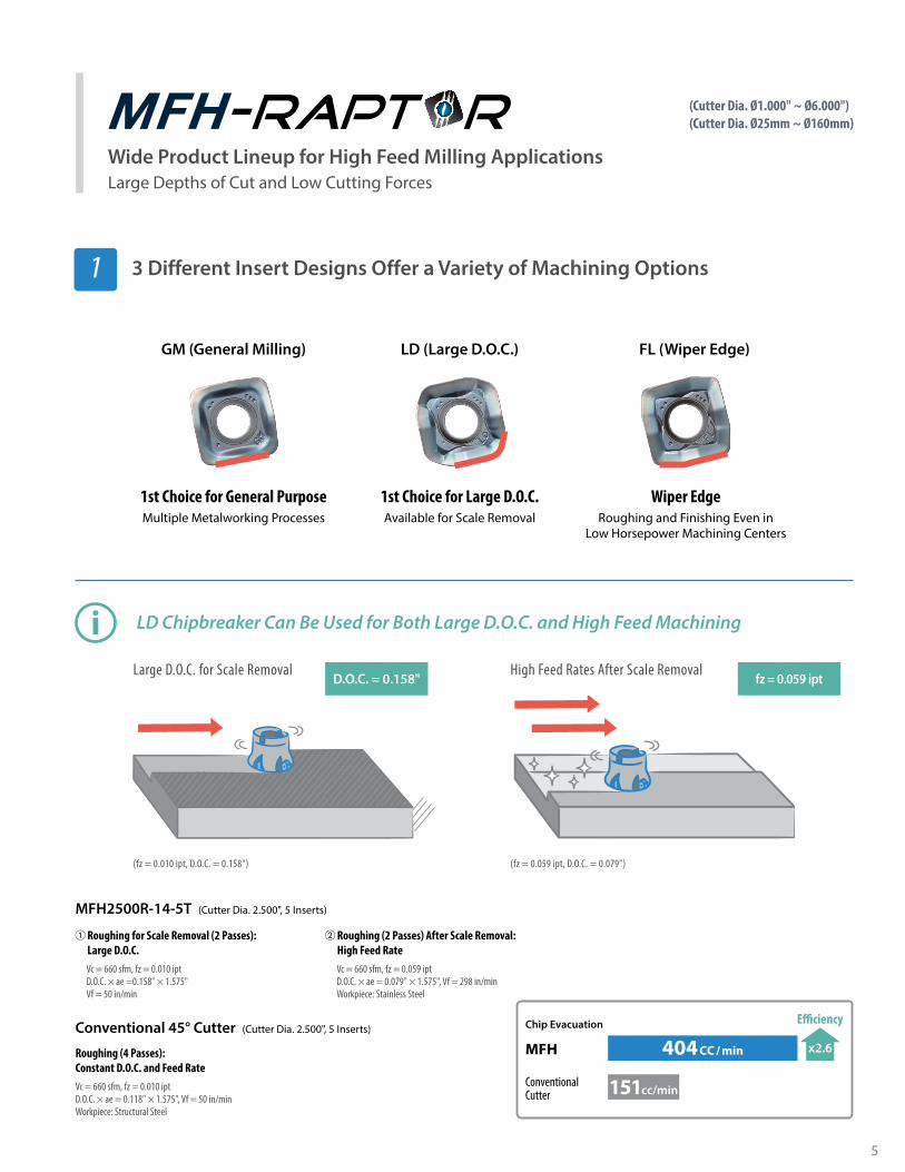
GM (General Milling) LD (Large D.O.C.) FL (Wiper Edge)
1st Choice for General Purpose 1st Choice for Large D.O.C. Wiper EdgeMultiple Metalworking Processes Available for Scale Removal Roughing and Finishing Even in
Low Horsepower Machining Centers
Roughing for Scale Removal (2 Passes): Large D.O.C.Vc = 660 sfm, fz = 0.010 iptD.O.C. × ae =0.158" × 1.575" Vf = 50 in/min
Roughing (4 Passes):Constant D.O.C. and Feed RateVc = 660 sfm, fz = 0.010 iptD.O.C. × ae = 0.118" × 1.575", Vf = 50 in/minWorkpiece: Structural Steel
Roughing (2 Passes) After Scale Removal: High Feed RateVc = 660 sfm, fz = 0.059 iptD.O.C. × ae = 0.079" × 1.575", Vf = 298 in/minWorkpiece: Stainless Steel
MFH2500R-14-5T (Cutter Dia. 2.500", 5 Inserts)
Conventional 45° Cutter (Cutter Dia. 2.500", 5 Inserts)
Large D.O.C. for Scale Removal High Feed Rates After Scale RemovalD.O.C. = 0.158" fz = 0.059 ipt
(fz = 0.010 ipt, D.O.C. = 0.158") (fz = 0.059 ipt, D.O.C. = 0.079")
Chip Evacuation
x2.6
E�ciency
MFH
ConventionalCutter
404CC / min
151cc/min
LD Chipbreaker Can Be Used for Both Large D.O.C. and High Feed Machining
(Cutter Dia. Ø1.000" ~ Ø6.000")(Cutter Dia. Ø25mm ~ Ø160mm)MFH-RAPT R(Cutter Dia. Ø0.625" ~ Ø2.000")
(Cutter Dia. Ø16mm ~ Ø50mm)
Wide Product Lineup for High Feed Milling ApplicationsLarge Depths of Cut and Low Cutting Forces
3 Different Insert Designs Offer a Variety of Machining Options1

6
Cracking Comparison by Diamond Indenter (In-house Evaluation)
Conventional MaterialPR1535 Base Material
High Toughness Carbide Base Material
23%
Fracture Toughness
Long CracksShort Cracks(High Impact Improvement)
ShockResistance
PR1535 MEGACOAT NANO Fracture resistant with a tough substrate and high heat-resistant coating for stable machining of general steel, mold steel, and difficult-to-cut materials
An increase in cobalt content yields a substrate with greater toughness. Fracture toughness values are improved by 23% over previous grades.
The coarse grain structure and uniform particle size correspond to improved heat resistance, with conductivity values decreased by 11%. The uniform structure also reduces crack propagation.
23% Improved Fracture Toughness1 Stability Improvement2
Oxidation Resistance
40
35
30
25
20
15
10400 600 800 1,000 1,200 1,400
Low High
TiCN
TiN
TiAIN
MEGACOAT NANO
Har
dnes
s (G
Pa)
Oxidation Temperature (°C)
40
35
30
25
20
15
100.3 0.4 0.5 0.6 0.7 0.8
Deposition ResistanceHigh Low
TiCN
TiN
TiAIN
MEGACOAT NANO
Har
dnes
s (G
Pa)
Wear Coe�cient (µ)
Cutting Time (min)
Wea
r (in
)
0.012
0.008
0.004
5 10 15 20 25 300
PR1535Competitor GCompetitor H
2.6xDefect
Resistance
Number of Impacts
PR1535
DefectDefectCompetitor E
DefectDefectCompetitor F
0 25,00020,00015,00010,0005,000
Cutting Conditions: Vc = 390 sfm, fz = 0.059 ipt, D.O.C. × ae = 0.016" × 0.098" Cutting Dia. Ø0.375", Dry Workpiece: H13 (40~45HRC)
Cutting Conditions: Vc = 590 sfm, fz = 0.020 ipt, D.O.C. x ae = 0.012 "× 0.315"Cutting Dia. Ø0.375", Dry Workpiece: 304
Defect Resistance Comparison (In-house Evaluation)
Coating Properties (Abrasion Resistance) Coating Properties (Deposition Resistance)
Abrasion Resistance Comparison (In-house Evaluation)
Achieves long tool life with the combination of a tough substrate and a special Nano coating layer
Stable machining with excellent wear resistance

7
Toolholder Dimensions (Inch Size)
Shank Part Number Stoc
k
No. o
fIn
serts Dimensions (in) Maximum
Ramping AngleRake Angle
(°) Coolant Hole Drawing Weight
(kg)Max.RPM
ClampScrew
DCX DC DCON LF LH APMX α A.R.
Standard(Cylindrical)
MFH 0375-S375-01-1T-3 � 1 0.375 0.225 0.375 3.000 0.7500.020
3°+5° � Fig. 1
0.04 16,200 SB-
1840TRP0500-S500-01-3T-3 Þ 3 0.500 0.350 0.500 3.000 0.750 2° 0.07 14,000 0625-S625-01-4T35 Þ 4 0.625 0.475 0.625 3.500 1.000 1.2° 0.12 11,400
Þ : Standard Item � : Quoted Item (Made to Order)
MFH Micro End Mill
Spare Parts and Applicable Inserts
Part Number
Spare Parts
Applicable Inserts� P8
Clamp Screw Wrench Anti-SeizeCompound
MFH…-01-… SB-1840TRP FTP-6 P-37 LPGT010210ER-GM
MFH0500-S500-01-3T-3
DC
DCX
Fig. 1
APMX
LF
DCO
Nh6
LH
DCX
LF
DC
LHAPMX
DCON
h6
DCON
h6
DCON
h6
DCX
LF
DC
LHAPMX
DCON
h6
Fig. 4
Fig. 5
Fig. 2
Fig. 3
Toolholder Dimensions (Metric Size)
Shank Part Number Stoc
k
No. o
fIn
serts Dimensions (in) Maximum
Ramping AngleRake Angle
(°) Coolant Hole Drawing Weight
(kg)Max.RPM
ClampScrew
DCX DC DCON LF LH APMX α A.R.
Standard(Cylindrical)
MFH 08-S10-01-1T Þ 1 8 4.2 10 75 16
0.5
4°
+5° � Fig. 2
0.04 20,000
SB-1840TRP
10-S10-01-2T Þ 2 10 6.2 10 80 20 3° 0.04 16,200 12-S12-01-3T Þ 3 12 8.2 12 80 20 2° 0.06 14,000 16-S16-01-4T Þ 4 16 12.2 16 90 25 1.2° 0.12 11,400
Over Size(Cylindrical) MFH 14-S12-01-3T Þ 3 14 10.2 12 80 20 0.5 1.5° +5° � Fig. 4 0.07 12,500
Standard(Weldon)
MFH 08-W10-01-1T Þ 1 8 4.2 10 58 16
0.5
4°
+5° � Fig. 3
0.03 20,000 10-W10-01-2T Þ 2 10 6.2 10 60 20 3° 0.03 16,200 12-W12-01-3T Þ 3 12 8.2 12 65 20 2° 0.05 14,000 16-W16-01-4T Þ 4 16 12.2 16 73 25 1.2° 0.1 11,400
Over Size(Weldon) MFH 14-W12-01-3T Þ 3 14 10.2 12 65 20 0.5 1.5° +5° � Fig. 5 0.05 12,500
Þ : Standard Item
Caution with Max. RevolutionWhen running an end mill or a cutter at the maximum revolution, the insert or cutter may be damaged by centrifugal force.
Coat Anti-Seize Compound (P-37) thinly on portion of taper and thread prior to installation.
Recommended Cutting Conditions � P9

8
Toolholder Dimensions (Metric Size)
Part Number Stoc
k
Unit
No. o
f Inse
rts Dimensions (mm)MaximumRamping
Angle A.R. Coolant Hole
Max.RPM
DCX DC DCSFMS DCON OAL LF CRKS H APMX α
MFH 0500-M06-01-3T Þinch
3 0.500 0.350 0.441 0.256 1.240 0.669 M6xP1.0 0.2760.020
2°
+5° �
14,000
0625-M08-01-4T Þ 4 0.625 0.475 0.579 0.335 1.575 0.866 M8xP1.25 0.472 1.2° 11,400
MFH 08-M06-01-1T ß
mm
1 8 4.29.2
6.5 31.5 17 M6×P1.0 7 0.5
4° 20,000
10-M06-01-2T ß 2 10 6.2 3° 16,200
12-M06-01-3T ß 3 12 8.211.2
2° 14,000
14-M06-01-3T ß 3 14 10.2 1.5° 12,500
16-M08-01-4T ß 4 16 12.2 14.7 8.5 40 22 M8×P1.25 12 1.2° 11,400
Þ : Standard Item
MFH Micro Modular End Mill
MFH Micro Applicable Inserts
HDCX
LF
DCS
FMS
ØdAPMX
OAL
DC
CRKS
A
AA-A Section
Industry standard threads for adapting to common toolholders (For Ø8mm - Ø14mm screw size: M6 x P1.0).Check screw specifications for the shank in use.
Spare Parts and Applicable Inserts
Part Number
Spare Parts
Applicable InsertsSee Below
Clamp Screw Wrench Anti-SeizeCompound
MFH…-01-… SB-1840TRP FTP-6 P-37 LPGT010210ER-GM
Actual End Mill Depth (MFH16-M080-01-4T)
LF
DC
LUX
ArborPart Number
Applicable End Mill Actual End Mill Depth (mm)
Part NumberCutting Dia. (mm) Dimension (mm)
LUXDC LF
BT30K-M08-45 MFH16-M08-01… Ø16 22 28.8
BT40K-M08-55 MFH16-M08-01… Ø16 22 28.7
Insert Part NumberDimension (in) MEGACOAT NANO CVD
W1 S D1 INSL RE PR1535 PR1525 CA6535
General Purpose
D1
SW1
INSL
RE
LPGT010210ER-GM 0.165 0.086 0.083 0.247 0.039 Þ Þ Þ
Þ : Standard Item
Caution with Max. RevolutionWhen running an end mill or a cutter at the maximum revolution, the insert or cutter may be damaged by centrifugal force.
Coat Anti-Seize Compound (P-37) thinly on portion of taper and thread prior to installation.
Recommended Cutting Conditions � P9

9
• Machining with coolant is recommended for Ni-base Heat Resistant Alloy and Titanium Alloy
• The number in bold font is recommended starting conditions. Adjust the cutting speed and the feed rate within the above conditions according to the actual machining situation.
• Internal coolant is recommended for slotting applications
Chipb
reak
er
Workpiece Material
Cutter Part Number and Feed Rate (fz: ipt) *Recommended D.O.C. = 0.012" Reference Value Recommended Insert Grade (Vc: sfm)
MFH08-…-1T MFH0375-…-1T-3MFH10-…-2T
MFH0500-…-3T(-3)MFH12-…-3T MFH14-…-3T MFH0625-…-4T(35)
MFH16-…-4TMEGACOAT NANO CVD Coated Carbide
PR1525 PR1535 CA6535
GM
Carbon Steel0.008~0.016~0.024 0.008~0.020~0.031
�390-590-820
�390-590-820 -
Alloy Steel �330-520-720
�330-520-720 -
Mold Steel( ~40 HRc)
0.008~0.012~0.020 0.008~0.016~0.024 �260-460-590
�260-460-590 -
Mold Steel( 40~50 HRc) 0.008~0.010~0.012 0.008~0.010~0.016 �
200-330-430�
200-330-430 -
AusteniticStainless Steel
0.008~0.012~0.020 0.008~0.016~0.024
�330-520-660
�330-520-660 -
MartensiticStainless Steel - �
490-660-820�
590-790-980
Precipitation Hardened Stainless Steel - �
300-390-490 -
Gray Cast Iron 0.008~0.016~0.024 0.008~0.020~0.031 �390-590-820 - -
Nodular Cast Iron 0.008~0.012~0.020 0.008~0.016~0.024 �330-490-660 - -
Ni-baseHeat-Resistant Alloy
0.008~0.010~0.012 0.008~0.010~0.016- �
70-100-160�
70-100-160
Titanium Alloy - �130-200-260 -
Recommended Cutting Conditions 1st Recommendation 2nd Recommendation
MFH Micro Cutting Performance
Feed fz (ipt)
Dep
th o
f Cut
D.O
.C. (
in)
0.020
0.016
0.012
0.008
0.020
0.016
0.012
0.008
0.008 0.016 0.024 0.032
Feed fz (ipt)
Dep
th o
f Cut
D.O
.C. (
in)
0.008 0.016 0.024 0.032
Feed fz (ipt)
Dep
th o
f Cut
D.O
.C. (
in)
0.020
0.016
0.012
0.008
0.020
0.016
0.012
0.008
0.008 0.016 0.024 0.032
Feed fz (ipt)
Dep
th o
f Cut
D.O
.C. (
in)
0.008 0.016 0.024 0.032
Cutter Dia: Ø0.375" ~ Ø0.500"Cutter Dia: Ø8mm ~ Ø12mm
Cutter Dia: Ø0.625"Cutter Dia: Ø14mm ~ Ø16mm
Chip Evacuation
PR1535
Competitor I
4.5 cc/min
3.4 cc/min
E�ciency
1.3x
Cutting Time
PR1535
Competitor J
7 min
35%
Cutting Time
11 min
Case Studies
PR1535 shows 1.3 times machining efficiency compared to Competitor IGood cutting edge condition after machining almost doubling the tool life (User Evaluation)
PR1535 shows 30% faster cycle time compared to competitor J
(User Evaluation)
Vc = 300 sfm (n = 2,400 rpm)fz = 0.011 ipr(Vf = 75.984 ipm)D.O.C. × ae = 0.012" × ~ 0.028", DryMFH0500-S500-01-3T-3LPGT010210ER-GM PR1535
Mold H13
Vc = 590 sfm (n = 3,580 rpm)fz = 0.016 ipt (Vf = 225.591 ipm)D.O.C. = 0.016", ae = 0.315", WetMFH0625-S625-01-4T35LPGT010210ER-GM PR1535
Industrial Machine Parts 440C

10
Toolholder Dimensions (Inch Size)
Part Number Stoc
k
No. o
f Inse
rts Dimensions (in) RampingAngle
Rake Angle(°)
Coola
nt H
ole
Draw
ing
Weig
ht(kg
)
Max
.RP
M
DCX DC DCON LF LH APMX α A.R. R.R.
Stan
dard
Shan
k(W
eldon
)
MFH 0625-W625-03-2T-3 Þ 2 0.625 0.310 0.625 3.196 1.250 0.039 2.8° -10° -15°
� Fig.2
0.1 18,800
0750-W750-03-3T-4 Þ 3 0.750 0.435 0.750 4.070 2.000 0.039 1.7° -10° -15° 0.2 15,700
1000-W100-03-4T47 Þ 4 1.000 0.685 1.000 4.820 2.500 0.039 1.2° -10° -15° 0.4 13,400
1000-W100-03-5T47 Þ 5 1.000 0.685 1.000 4.820 2.500 0.039 1.2° -10° -15° 0.4 13,400
1250-W125-03-5T-5 Þ 5 1.250 0.935 1.250 5.070 2.750 0.039 0.8° -10° -15° 0.7 11,400
1250-W125-03-6T-5 Þ 6 1.250 0.935 1.250 5.070 2.750 0.039 0.8° -10° -15° 0.7 11,400
Long
Shan
k(Cy
lindr
ical)
MFH 0625-S625-03-2T-6 Þ 2 0.625 0.310 0.625 6.000 2.000 0.039 2.8° -10° -15°
� Fig.1
0.2 18,800
0750-S750-03-3T65 Þ 3 0.750 0.435 0.750 6.500 3.000 0.039 1.7° -10° -15° 0.3 15,700
1000-S100-03-4T-7 Þ 4 1.000 0.685 1.000 7.000 4.000 0.039 1.2° -10° -15° 0.6 13,400
1250-S125-03-5T-8 Þ 5 1.250 0.935 1.250 8.000 4.750 0.039 0.8° -10° -15° 1.1 11,400
Þ : Standard Item
MFH Mini End Mill (Inch Size)
Spare Parts and Applicable Inserts (Inch Size)
Part Number
Spare Parts
Applicable Inserts� P14
Clamp Screw Wrench Anti-SeizeCompound
MFH…-03-… SB-3065TRPDTPM-8
Recommended Torque for Insert Clamp 1.2 N·m
P-37 LOGU030310ER-GM
Standard (Cylindrical)
Caution with Max. RevolutionWhen running an end mill or a cutter at the maximum revolution, the insert or cutter may be damaged by centrifugal force.
Coat Anti-Seize Compound (P-37) thinly on portion of taper and thread prior to installation.
Recommended Cutting Conditions � P15
DCX
DC
Fig.1
Fig.2
APMXLH
LF
DCO
Nh6
DCO
Nh6

11
Toolholder Dimensions (Metric Size)
Part Number Stoc
k
No. o
f Inse
rts Dimensions (mm) RampingAngle
Rake Angle(°)
Coola
nt H
ole
Draw
ing
Weig
ht(kg
)
Max
.RP
M
DCX DC DCON LF LH APMX α A.R. R.R.
Stan
dard
Shan
k(Cy
lindr
ical)
MFH 16-S16-03-2T Þ 2 16 8 16 100 30 1 2.8° -10° -15° � Fig.1 0.1 18,800 17-S16-03-2T Þ 2 17 9 16 100 20 1 2.5° -10° -15°
� Fig.20.1 17,900
18-S16-03-2T Þ 2 18 10 16 100 20 1 2.1° -10° -15° 0.1 17,000 20-S20-03-3T Þ 3 20 12 20 130 50 1 1.7° -10° -15°
� Fig.10.3 15,700
20-S20-03-4T Þ 4 20 12 20 130 50 1 1.7° -10° -15° 0.3 15,700 22-S20-03-3T Þ 3 22 14 20 130 30 1 1.4° -10° -15°
� Fig.20.3 14,700
22-S20-03-4T Þ 4 22 14 20 130 30 1 1.4° -10° -15° 0.3 14,70025-S25-03-4T Þ 4 25 17 25 140 60 1 1.2° -10° -15°
� Fig.10.5 13,400
25-S25-03-5T Þ 5 25 17 25 140 60 1 1.2° -10° -15° 0.5 13,400 28-S25-03-4T Þ 4 28 20 25 140 40 1 1.0° -10° -15°
� Fig.20.5 12,400
28-S25-03-5T Þ 5 28 20 25 140 40 1 1.0° -10° -15° 0.5 12,400 32-S32-03-5T Þ 5 32 24 32 150 70 1 0.8° -10° -15°
� Fig.10.8 11,400
32-S32-03-6T Þ 6 32 24 32 150 70 1 0.8° -10° -15° 0.8 11,400
Stan
dard
Shan
k(W
eldon
)
MFH 16-W16-03-2T Þ 2 16 8 16 79 30 1 2.8° -10° -15°
� Fig.3
0.1 18,80020-W20-03-3T Þ 3 20 12 20 101 50 1 1.7° -10° -15° 0.2 15,700 20-W20-03-4T Þ 4 20 12 20 101 50 1 1.7° -10° -15° 0.2 15,700 25-W25-03-4T Þ 4 25 17 25 117 60 1 1.2° -10° -15° 0.4 13,400 25-W25-03-5T Þ 5 25 17 25 117 60 1 1.2° -10° -15° 0.4 13,400 32-W32-03-5T Þ 5 32 24 32 131 70 1 0.8° -10° -15° 0.7 11,400 32-W32-03-6T Þ 6 32 24 32 131 70 1 0.8° -10° -15° 0.7 11,400
Long
Shan
k(Cy
lindr
ical) MFH 16-S16-03-2T-150 Þ 2 16 8 16 150 50 1 2.8° -10° -15°
� Fig.1
0.2 18,800 20-S20-03-3T-160 Þ 3 20 12 20 160 80 1 1.7° -10° -15° 0.3 15,700 25-S25-03-4T-180 Þ 4 25 17 25 180 100 1 1.2° -10° -15° 0.6 13,400 32-S32-03-5T-200 Þ 5 32 24 32 200 120 1 0.8° -10° -15° 1.1 11,400
Þ : Standard Item
MFH Mini End Mill (Metric Size)
Spare Parts and Applicable Inserts (Inch Size)
Part Number
Spare Parts
Applicable Inserts� P14
Clamp Screw Wrench Anti-SeizeCompound
MFH…-03-… SB-3065TRPDTPM-8
Recommended Torque for Insert Clamp 1.2 N·m
P-37 LOGU030310ER-GM
Fig.1
Fig.2
Fig.3
APMX
APMX
LHLF
DCON
h6
DCO
Nh6
DCO
Nh6
DC
DC
DCX
DCX
LHLF
Standard (Cylindrical)
Caution with Max. RevolutionWhen running an end mill or a cutter at the maximum revolution, the insert or cutter may be damaged by centrifugal force.
Coat Anti-Seize Compound (P-37) thinly on portion of taper and thread prior to installation.
Recommended Cutting Conditions � P15

12
Toolholder Dimensions (Inch Size)
Toolholder Dimensions (Metric Size)
Part Number Stock No. of Inserts
Dimensions (in) Rake Angle(°) Coolant
HoleWeight
(kg)Max.RPM
DCX DC DCSFMS DCB DCCB1 DCCB2 LF CBDP KDP KWW APMX A.R. R.R.
MFH 1500R-03-5T Þ 51.500 1.185 1.400 0.500 0.433 0.276 1.575 0.709 0.156 0.250 0.039 -10° -15° � 0.2 10,200
1500R-03-6T Þ 6
2000R-03-8T Þ 8 2.000 1.685 1.750 0.750 0.669 0.433 1.968 0.947 0.188 0.312 0.039 -10° -15° � 0.5 8,600
Part Number Stock No. of Inserts
Dimensions (mm) Rake Angle(°) Coolant
HoleWeight
(kg)Max.RPM
DCX DC DCSFMS DCB DCCB1 DCCB2 LF CBDP KDP KWW APMX A.R. R.R.
MFH 040R-03-5T-M Þ 5 40 32 38 16 15 9 40 19 5.6 8.41 -10° -15° � 0.2 9,900
040R-03-6T-M Þ 6 40 32 38 16 15 9 40 19 5.6 8.4
MFH 050R-03-8T-M Þ 8 50 42 47 22 19 11 50 21 6.3 10.4 1 -10° -15° � 0.5 8,600
Þ : Standard Item
MFH Mini Face Mill
Spare Parts and Applicable Inserts (Inch Size)
Part Number
Spare Parts
Applicable Inserts� P14
Clamp Screw Wrench Anti-SeizeCompound Arbor Bolt
MFH1500-03-5T
SB-3065TRPDTPM-8
Recommended Torque for Insert Clamp 1.2 N·m
P-37HH1/4-0.75
LOGU030310ER-GMMFH1500-03-6T
MFH2000-03-8T HH3/8-1.25
Caution with Max. RevolutionWhen running an end mill or a cutter at the maximum revolution, the insert or cutter may be damaged by centrifugal force.
Coat Anti-Seize Compound (P-37) thinly on portion of taper and thread prior to installation.
Recommended Cutting Conditions � P15
Multiple step slot milling is NOT recommended for MFH-Mini face mill diameters above Ø1.300" due to a danger of re-cutting chips
APM
XLF
KWWDCBDCSFMS
KDP
CBD
P
DCCB2
DCCB1
DCDCX

13
Toolholder Dimensions
Part Number Stoc
k
Unit
No. o
fIn
serts
Dimensions RampingAngle
Rake Angle(°)
Coola
ntHo
le
Max
.RP
M
DCX DC DCSFMS DCON OAL LF CRKS(mm) H APMX α A.R. R.R.
MFH 0625-M08-03-2T Þ
inch
2 0.625 0.310 0.579 0.335 1.693 0.984 M8xP1.25 0.472 0.039 2.8° -10° -15° � 18,800
MFH 0750-M10-03-3T Þ 3 0.750 0.435 0.728 0.413 1.929 1.181 M10xP1.5 0.591 0.039 1.7° -10° -15° � 15,700
MFH 1000-M12-03-4T Þ 4 1.000 0.685 0.906 0.492 2.244 1.378 M12xP1.75 0.748 0.039 1.2° -10° -15° � 13,400
1000-M12-03-5T Þ 5 1.000 0.685 0.906 0.492 2.244 1.378 M12xP1.75 0.748 0.039 1.2° -10° -15° � 13,400
MFH 1250-M16-03-5T Þ 5 1.250 0.935 1.181 0.669 2.480 1.575 M16xP2 0.945 0.039 0.8° -10° -15° � 11,400
1250-M16-03-6T Þ 6 1.250 0.935 1.181 0.669 2.480 1.575 M16xP2 0.945 0.039 0.8° -10° -15° � 11,400
MFH 16-M08-03-2T Þ
mm
2 16 8 14.7 8.5 43 25 M8xP1.25 12 1 2.8° -10° -15° � 18,880
MFH 17-M08-03-2T Þ 2 17 9 14.7 8.5 43 25 M8xP1.25 12 1 2.5° -10° -15° � 17,900
MFH 18-M08-03-2T Þ 2 18 10 14.7 8.5 43 25 M8xP1.25 12 1 2.1° -10° -15° � 17,000
MFH 20-M10-03-3T Þ 3 20 12 18.7 10.5 49 30 M10xP1.5 15 1 1.7° -10° -15° � 15,700
20-M10-03-4T Þ 4 20 12 18.7 10.5 49 30 M10xP1.5 15 1 1.7° -10° -15° � 15,700
MFH 22-M10-03-3T Þ 3 22 14 18.7 10.5 49 30 M10xP1.5 15 1 1.4° -10° -15° � 14,700
22-M10-03-4T Þ 4 22 14 18.7 10.5 49 30 M10xP1.5 15 1 1.4° -10° -15° � 14,700
MFH 25-M12-03-4T Þ 4 25 17 23 12.5 57 35 M12xP1.75 19 1 1.2° -10° -15° � 13,400
25-M12-03-5T Þ 5 25 17 23 12.5 57 35 M12xP1.75 19 1 1.2° -10° -15° � 13,400
MFH 28-M12-03-4T Þ 4 28 20 23 12.5 57 35 M12xP1.75 19 1 1.0° -10° -15° � 12,400
28-M12-03-5T Þ 5 28 20 23 12.5 57 35 M12xP1.75 19 1 1.0° -10° -15° � 12,400
MFH 32-M16-03-5T Þ 5 32 24 30 17 63 40 M16xP2 24 1 0.8° -10° -15° � 11,400
32-M16-03-6T Þ 6 32 24 30 17 63 40 M16xP2 24 1 0.8° -10° -15° � 11,400
Þ : Standard Item
MFH Mini Modular End Mill
Spare Parts and Applicable Inserts
Part Number
Spare Parts
Applicable Inserts� P14
Clamp Screw Wrench Anti-SeizeCompound
MFH…-03-… SB-3065TRPDTPM-8
Recommended Torque for Insert Clamp 1.2 N·m
P-37 LOGU030310ER-GM
Caution with Max. RevolutionWhen running an end mill or a cutter at the maximum revolution, the insert or cutter may be damaged by centrifugal force.
Coat Anti-Seize Compound (P-37) thinly on portion of taper and thread prior to installation.
Recommended Cutting Conditions � P15
APMX
LF
OAL
CRKS
A
AH
DC
DCO
N
DCSF
MS
DCX
A-A Section

14
Insert Part NumberDimension (in) MEGACOAT NANO CVD
W1 S D1 INSL RE PR1535 PR1525 PR1510 CA6535
General Purpose
LOGU030310ER-GM 0.244 0.156 0.136 0.469 0.039 Þ Þ Þ Þ
S
INSL
W1
RE
D1
Þ : Standard Item
Applicable Inserts
Caution: When using fine pitch, reduce the cutting conditions compared with standard type
Fine Pitch End Mill Standard Pitch End MillCutting Dia. Ø0.625" - Ø0.750"Cutting Dia. Ø16mm - Ø22mm
Standard Pitch End MillCutting Dia. 1.000" - 1.250"Cutting Dia. Ø25mm - Ø32mm
MFH Mini Face MillCutting Dia. 1.500" - 2.000"Cutting Dia. Ø40mm - Ø50mm
0.012
0.032
Feed Rate fz (ipt)
D.O
.C. (
in)
0.020 0.039 0.059
0.039
0.020
0.024
0.047
Feed Rate fz (ipt)
D.O
.C. (
in)
0.020 0.039 0.059
0.039
0.020
Feed Rate fz (ipt)
D.O
.C. (
in)
0.020 0.039 0.059
0.039
0.020
0.032
Feed Rate fz (ipt)
D.O
.C. (
in)
0.020 0.039 0.059
0.039
0.020
0.032
MFH Mini Cutting Performance (GM Chipbreaker)
Actual End Mill Depth (BT Arbor Metric)
LF
DC
LUX
ArborPart Number
Applicable End Mill Actual End Mill Depth (mm)
Part NumberCutting Dia. (mm) Dimension (mm)
LUXDC LF
BT30K-M08-45
MFH16-M08-03… Ø16 25 31.8
MFH17-M08-03… Ø17 25 33.2
MFH18-M08-03… Ø18 25 34.2
BT30K-M10-45 MFH20-M10-03… Ø20 30 36.8
MFH22-M10-03… Ø22 30 39.2
BT30K-M12-45MFH25-M12-03… Ø25 35 42.8
MFH28-M12-03… Ø28 35 45.5
BT40K-M08-55
MFH16-M08-03… Ø16 25 31.7
MFH17-M08-03… Ø17 25 33.2
MFH18-M08-03… Ø18 25 34.3
BT40K-M10-60 MFH20-M10-03… Ø20 30 38.7
MFH22-M10-03… Ø22 30 44.5
BT40K-M12-55 MFH25-M12-03… Ø25 35 44.6
MFH28-M12-03… Ø28 35 47.6
BT40K-M16-65 MFH32-M16-03… Ø32 40 51.2
For BT Arbor See � P26
15
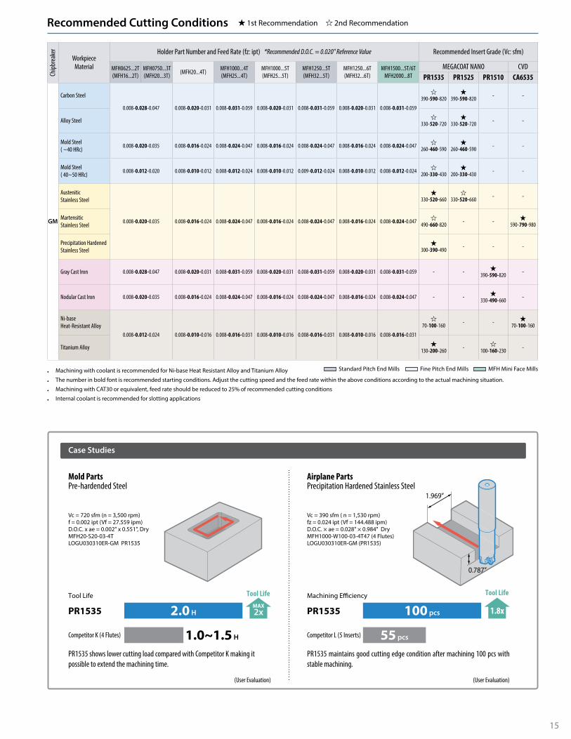
• Machining with coolant is recommended for Ni-base Heat Resistant Alloy and Titanium Alloy
• The number in bold font is recommended starting conditions. Adjust the cutting speed and the feed rate within the above conditions according to the actual machining situation.
• Machining with CAT30 or equivalent, feed rate should be reduced to 25% of recommended cutting conditions
• Internal coolant is recommended for slotting applications
Chipb
reak
erWorkpiece
Material
Holder Part Number and Feed Rate (fz: ipt) *Recommended D.O.C. = 0.020" Reference Value Recommended Insert Grade (Vc: sfm)
MFH0625...2T(MFH16...2T)
MFH0750...3T(MFH20...3T) (MFH20...4T) MFH1000...4T
(MFH25...4T)MFH1000...5T(MFH25...5T)
MFH1250...5T(MFH32...5T)
MFH1250...6T(MFH32...6T)
MFH1500...5T/6TMFH2000...8T
MEGACOAT NANO CVDPR1535 PR1525 PR1510 CA6535
GM
Carbon Steel
0.008-0.028-0.047 0.008-0.020-0.031 0.008-0.031-0.059 0.008-0.020-0.031 0.008-0.031-0.059 0.008-0.020-0.031 0.008-0.031-0.059
�390-590-820
�390-590-820 - -
Alloy Steel �330-520-720
�330-520-720 - -
Mold Steel( ~40 HRc) 0.008-0.020-0.035 0.008-0.016-0.024 0.008-0.024-0.047 0.008-0.016-0.024 0.008-0.024-0.047 0.008-0.016-0.024 0.008-0.024-0.047 �
260-460-590�
260-460-590 - -
Mold Steel( 40~50 HRc) 0.008-0.012-0.020 0.008-0.010-0.012 0.008-0.012-0.024 0.008-0.010-0.012 0.009-0.012-0.024 0.008-0.010-0.012 0.008-0.012-0.024 �
200-330-430�
200-330-430 - -
AusteniticStainless Steel
0.008-0.020-0.035 0.008-0.016-0.024 0.008-0.024-0.047 0.008-0.016-0.024 0.008-0.024-0.047 0.008-0.016-0.024 0.008-0.024-0.047
�330-520-660
�330-520-660 - -
MartensiticStainless Steel
�490-660-820 - - �
590-790-980
Precipitation Hardened Stainless Steel
�300-390-490 - - -
Gray Cast Iron 0.008-0.028-0.047 0.008-0.020-0.031 0.008-0.031-0.059 0.008-0.020-0.031 0.008-0.031-0.059 0.008-0.020-0.031 0.008-0.031-0.059 - - �390-590-820 -
Nodular Cast Iron 0.008-0.020-0.035 0.008-0.016-0.024 0.008-0.024-0.047 0.008-0.016-0.024 0.008-0.024-0.047 0.008-0.016-0.024 0.008-0.024-0.047 - - �330-490-660 -
Ni-baseHeat-Resistant Alloy
0.008-0.012-0.024 0.008-0.010-0.016 0.008-0.016-0.031 0.008-0.010-0.016 0.008-0.016-0.031 0.008-0.010-0.016 0.008-0.016-0.031
�70-100-160 - - �
70-100-160
Titanium Alloy �130-200-260 - �
100-160-230 -
Recommended Cutting Conditions 1st Recommendation 2nd Recommendation
Standard Pitch End Mills Fine Pitch End Mills MFH Mini Face Mills
Case Studies
Airplane PartsPrecipitation Hardened Stainless Steel
Mold PartsPre-hardended Steel
PR1535 maintains good cutting edge condition after machining 100 pcs with stable machining.
(User Evaluation)
Machining E�ciency
100 pcs
55 pcs
1.8x
Tool Life
PR1535
Competitor L (5 Inserts)
PR1535 shows lower cutting load compared with Competitor K making it possible to extend the machining time.
(User Evaluation)
Tool Life
2.0 H
1.0~1.5 H
MAX2x
Tool Life
PR1535
Competitor K (4 Flutes)
Vc = 720 sfm (n = 3,500 rpm)f = 0.002 ipt (Vf = 27.559 ipm)D.O.C. x ae = 0.002" x 0.551", DryMFH20-S20-03-4TLOGU030310ER-GM PR1535
Vc = 390 sfm ( n = 1,530 rpm)fz = 0.024 ipt (Vf = 144.488 ipm)D.O.C. × ae = 0.028" × 0.984" DryMFH1000-W100-03-4T47 (4 Flutes)LOGU030310ER-GM (PR1535)
1.969”
0.787”

16
KWWDCB
DCSFMS
KDP
CBD
P
LFA
PMX
DCCB2DCCB1
DCDCX
DCCB2DCCB1
DCDCX
DCCB1DCDCX
Fig.1
KWWDCB
DCSFMS
KDP
CBD
P
APM
X LF
Fig.3
KWWDCB
DCSFMS
KDP
CBD
P
LFA
PMX
Fig.2
3/8 24UNF(Left-hand Thread)
Toolholder Dimensions with SOMT10 Inserts (Inch Size)
Toolholder Dimensions with SOMT14 Inserts (Inch Size)
Part Number Stoc
k
No. o
f Inse
rts Dimensions (in) Rake Angle (°)
Coola
nt H
ole
Draw
ing
Weig
ht(kg
)M
ax.
RPM
DCXDC
DCSFMS DCB DCCB1 DCCB2 LF CBDP KDP KWW APMX *1APMX2 A.R. R.R.GM LD FL
MFH 2000R-10-4T Þ 4 2.000 1.331 1.510 1.469 1.750 0.750 0.669 0.433 1.969 0.947 0.187 0.313
0.059*2(0.138)
0.047
+10° -5°
� Fig.1
0.4 10,000
2000R-10-5T Þ 5 2.000 1.331 1.510 1.469 1.750 0.750 0.669 0.433 1.969 0.947 0.187 0.313 +10° -5° 0.4 10,000
MFH 2500R-10-5T Þ 5 2.500 1.831 2.010 1.969 2.250 0.750 0.669 0.433 1.969 0.75 0.187 0.313 +10° -4° 0.7 8,800
2500R-10-6T Þ 6 2.500 1.831 2.010 1.969 2.250 0.750 0.669 0.433 1.969 0.75 0.187 0.313 +10° -4° 0.7 8,800
MFH 3000R-10-7T Þ 7 3.000 2.331 2.510 2.469 2.750 1.000 0.866 0.551 2.48 1.063 0.236 0.382 +10° -4° 1.3 7,600
Part Number Stoc
k
No. o
f Inse
rts Dimensions (in) Rake Angle (°)
Coola
nt H
ole
Draw
ing
Weig
ht(kg
)M
ax.
RPM
DCXDC
DCSFMS DCB DCCB1 DCCB2 LF CBDP KDP KWW APMX *1APMX2 A.R. R.R.GM LD FL
MFH 2000R-14-4T Þ 4 2.000 1.094 1.330 1.291 1.750 0.750 0.500 3/8 24UNF 1.969 0.827 0.187 0.313
0.079*2(0.197)
0.079
+10° -10° � Fig.2 0.4 8,800
MFH 2500R-14-4T Þ 4 2.500 1.594 1.830 1.791 2.250 0.750 0.669 0.433 1.969 0.750 0.187 0.313 +10° -10°
� Fig.1
0.6 7,400
2500R-14-5T Þ 5 2.500 1.594 1.830 1.791 2.250 0.750 0.669 0.433 1.969 0.750 0.187 0.313 +10° -10° 0.6 7,400
MFH 3000R-14-5T Þ 5 3.000 2.094 2.330 2.291 2.750 1.000 0.866 0.551 2.480 1.063 0.236 0.382 +10° -9° 1.2 6,400
3000R-14-6T Þ 6 3.000 2.094 2.330 2.291 2.750 1.000 0.866 0.551 2.480 1.063 0.236 0.382 +10° -9° 1.2 6,400
MFH 4000R-14-6T Þ 6 4.000 3.094 3.330 3.291 3.750 1.500 1.299 0.866 2.48 1.181 0.394 0.626 +10° -7° 2.3 5,600
4000R-14-7T Þ 7 4.000 3.094 3.330 3.291 3.750 1.500 1.299 0.866 2.48 1.181 0.394 0.626 +10° -7° 2.3 5,600
MFH 5000R-14-7T Þ 7 5.000 4.094 4.330 4.291 3.750 1.500 2.047 - 2.48 1.496 0.394 0.626 +10° -7° � Fig.3 2.9 4,800
MFH 6000R-14-8T Þ 8 6.000 5.094 5.330 5.291 4.880 2.000 2.835 - 2.48 1.496 0.433 0.752 +10° -6° × Fig.3 4.5 4,200
Spare Parts and Applicable Inserts (Inch Size)
Part Number
Spare Parts
Applicable Inserts� P23
Clamp Screw Wrench Anti-SeizeCompound
MountingBolt
DTPM TTP
MFH2000R-10-4T
SB-4090TRPNDTPM-15
Recommended Torque for Insert Clamp 3.5 N·m
P-37HH3/8-1.25(H) SOMT100420ER-GM
SOMT100420ER-LDSOMT100420ER-FL
MFH2000R-10-5TMFH2500R-10-5TMFH2500R-10-6TMFH3000R-10-7T HH1/2-1.25(H)MFH2000R-14-4T
SB-50120TRPTTP-20
Recommended Torque for Insert Clamp 4.5 N·m
P-37
XNS610*2
SOMT140520ER-GMSOMT140520ER-LDSOMT140514ER-FL
MFH2500R-14-4THH3/8-1.25(H)
MFH2500R-14-5TMFH3000R-14-5T
HH1/2-1.25(H)MFH3000R-14-6TMFH4000R-14-6T
-MFH4000R-14-7TMFH5000R-14-7TMFH6000R-14-8T
Caution with Max. RevolutionWhen running an end mill or a cutter at the maximum revolution, the insert or cutter may be damaged by centrifugal force.
Coat Anti-Seize Compound (P-37) thinly on portion of taper and thread prior to installation.
*2 Differential screw (3/8-24UNF)
MFH Face Mill (Inch Size)
APM
X2AP
MX
14°
(16°
)
45°75°
DCDCX
LD ChipbreakerCutting Edge Dimensions
Angle in ( ) is for SOMT14 Type
Recommended Cutting Conditions � P24-25(H) Optional coolant thru bolt available.
Þ : Standard Item *1 Refer to LD cutting edge dimensions in figure below
*2 Dimension in ( ) is when mounting LD
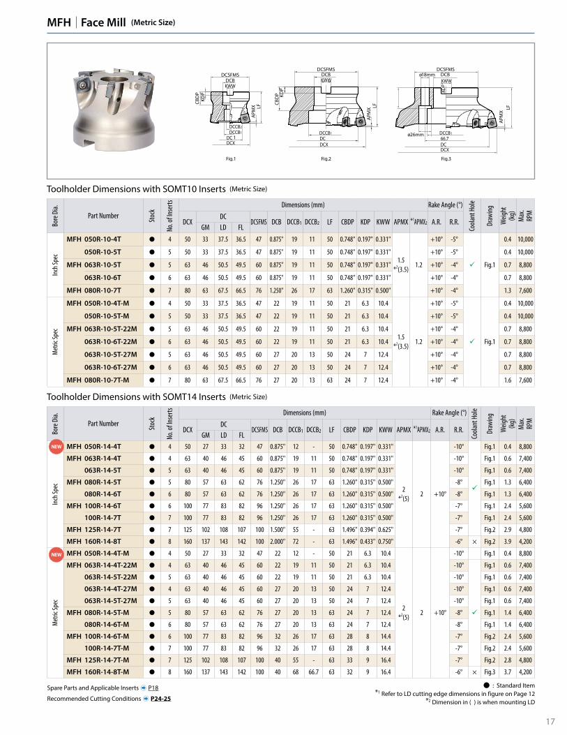
17
Bore
Dia.
Part Number Stoc
k
No. o
f Inse
rts Dimensions (mm) Rake Angle (°)
Coola
nt H
ole
Draw
ing
Weig
ht(kg
)M
ax.
RPM
DCXDC
DCSFMS DCB DCCB1 DCCB2 LF CBDP KDP KWW APMX *1APMX2 A.R. R.R.GM LD FL
Inch
Spec
MFH 050R-14-4T Þ 4 50 27 33 32 47 0.875" 12 - 50 0.748" 0.197" 0.331"
2*2(5)
2 +10°
-10°
�
Fig.1 0.4 8,800
MFH 063R-14-4T Þ 4 63 40 46 45 60 0.875" 19 11 50 0.748" 0.197" 0.331" -10° Fig.1 0.6 7,400
063R-14-5T Þ 5 63 40 46 45 60 0.875" 19 11 50 0.748" 0.197" 0.331" -10° Fig.1 0.6 7,400
MFH 080R-14-5T Þ 5 80 57 63 62 76 1.250" 26 17 63 1.260" 0.315" 0.500" -8° Fig.1 1.3 6,400
080R-14-6T Þ 6 80 57 63 62 76 1.250" 26 17 63 1.260" 0.315" 0.500" -8° Fig.1 1.3 6,400
MFH 100R-14-6T Þ 6 100 77 83 82 96 1.250" 26 17 63 1.260" 0.315" 0.500" -7° Fig.1 2.4 5,600
100R-14-7T Þ 7 100 77 83 82 96 1.250" 26 17 63 1.260" 0.315" 0.500" -7° Fig.1 2.4 5,600
MFH 125R-14-7T Þ 7 125 102 108 107 100 1.500" 55 - 63 1.496" 0.394" 0.625" -7° Fig.2 2.9 4,800
MFH 160R-14-8T Þ 8 160 137 143 142 100 2.000" 72 - 63 1.496" 0.433" 0.750" -6° × Fig.2 3.9 4,200
Met
ric Sp
ec
MFH 050R-14-4T-M Þ 4 50 27 33 32 47 22 12 - 50 21 6.3 10.4
2*2(5)
2 +10°
-10° Fig.1 0.4 8,800
MFH 063R-14-4T-22M Þ 4 63 40 46 45 60 22 19 11 50 21 6.3 10.4 -10°
�
Fig.1 0.6 7,400
063R-14-5T-22M Þ 5 63 40 46 45 60 22 19 11 50 21 6.3 10.4 -10° Fig.1 0.6 7,400
063R-14-4T-27M Þ 4 63 40 46 45 60 27 20 13 50 24 7 12.4 -10° Fig.1 0.6 7,400
063R-14-5T-27M Þ 5 63 40 46 45 60 27 20 13 50 24 7 12.4 -10° Fig.1 0.6 7,400
MFH 080R-14-5T-M Þ 5 80 57 63 62 76 27 20 13 63 24 7 12.4 -8° Fig.1 1.4 6,400
080R-14-6T-M Þ 6 80 57 63 62 76 27 20 13 63 24 7 12.4 -8° Fig.1 1.4 6,400
MFH 100R-14-6T-M Þ 6 100 77 83 82 96 32 26 17 63 28 8 14.4 -7° Fig.2 2.4 5,600
100R-14-7T-M Þ 7 100 77 83 82 96 32 26 17 63 28 8 14.4 -7° Fig.2 2.4 5,600
MFH 125R-14-7T-M Þ 7 125 102 108 107 100 40 55 - 63 33 9 16.4 -7° Fig.2 2.8 4,800
MFH 160R-14-8T-M Þ 8 160 137 143 142 100 40 68 66.7 63 32 9 16.4 -6° × Fig.3 3.7 4,200
NEW
Toolholder Dimensions with SOMT10 Inserts (Metric Size)
Toolholder Dimensions with SOMT14 Inserts (Metric Size)
Bore
Dia.
Part Number Stoc
k
No. o
f Inse
rts Dimensions (mm) Rake Angle (°)
Coola
nt H
ole
Draw
ing
Weig
ht(kg
)M
ax.
RPM
DCXDC
DCSFMS DCB DCCB1 DCCB2 LF CBDP KDP KWW APMX *1APMX2 A.R. R.R.GM LD FL
Inch
Spec
MFH 050R-10-4T Þ 4 50 33 37.5 36.5 47 0.875" 19 11 50 0.748" 0.197" 0.331"
1.5*2(3.5)
1.2
+10° -5°
� Fig.1
0.4 10,000
050R-10-5T Þ 5 50 33 37.5 36.5 47 0.875" 19 11 50 0.748" 0.197" 0.331" +10° -5° 0.4 10,000
MFH 063R-10-5T Þ 5 63 46 50.5 49.5 60 0.875" 19 11 50 0.748" 0.197" 0.331" +10° -4° 0.7 8,800
063R-10-6T Þ 6 63 46 50.5 49.5 60 0.875" 19 11 50 0.748" 0.197" 0.331" +10° -4° 0.7 8,800
MFH 080R-10-7T Þ 7 80 63 67.5 66.5 76 1.250" 26 17 63 1.260" 0.315" 0.500" +10° -4° 1.3 7,600
Met
ric Sp
ec
MFH 050R-10-4T-M Þ 4 50 33 37.5 36.5 47 22 19 11 50 21 6.3 10.4
1.5*2(3.5)
1.2
+10° -5°
� Fig.1
0.4 10,000
050R-10-5T-M Þ 5 50 33 37.5 36.5 47 22 19 11 50 21 6.3 10.4 +10° -5° 0.4 10,000
MFH 063R-10-5T-22M Þ 5 63 46 50.5 49.5 60 22 19 11 50 21 6.3 10.4 +10° -4° 0.7 8,800
063R-10-6T-22M Þ 6 63 46 50.5 49.5 60 22 19 11 50 21 6.3 10.4 +10° -4° 0.7 8,800
063R-10-5T-27M Þ 5 63 46 50.5 49.5 60 27 20 13 50 24 7 12.4 +10° -4° 0.7 8,800
063R-10-6T-27M Þ 6 63 46 50.5 49.5 60 27 20 13 50 24 7 12.4 +10° -4° 0.7 8,800
MFH 080R-10-7T-M Þ 7 80 63 67.5 66.5 76 27 20 13 63 24 7 12.4 +10° -4° 1.6 7,600
Þ : Standard Item *1 Refer to LD cutting edge dimensions in figure on Page 12
*2 Dimension in ( ) is when mounting LD
NEW
MFH Face Mill (Metric Size)
KD
P
ø18mm
ø26mmDCCB1 DCCB166.7DCDCDCXDCX
KWW KWWDCB DCB
DCSFMS DCSFMS
KDP
CBD
P
APM
X
APM
X
LF LF
1
KWWDCB
DCSFMS
KDP
CBD
P
LFA
PMX
DCCB2DCCB1
DCDCX
Fig.1 Fig.3Fig.2
Recommended Cutting Conditions � P24-25
Spare Parts and Applicable Inserts � P18

18
Spare Parts and Applicable Inserts (Metric Size)
Part Number
Spare Parts
Applicable Inserts� P23
Clamp Screw Wrench Anti-SeizeCompound
MountingBolt
DTPM TTP
MFH050R-10-…(-M)
SB-4090TRPNDTPM-15
Recommended Torque for Insert Clamp 3.5 N·m
P-37
HH10×30
SOMT100420ER-GMSOMT100420ER-LDSOMT100420ER-FL
MFH063R-10-…(-22M) HH10×30
MFH063R-10-…-27M HH12×35
MFH080R-10-… HH16×40
MFH080R-10-…-M HH12×35
MFH050R-14-…(-M)
SB-50120TRPTTP-20
Recommended Torque for Insert Clamp 4.5 N·m
P-37
W10×30
SOMT140520ER-GMSOMT140520ER-LDSOMT140514ER-FL
MFH063R-14-…(-22M) HH10×30
MFH063R-14-…-27M HH12×35
MFH080R-14-… HH16×40
MFH080R-14-…-M HH12×35
MFH100R-14-… HH16×40
MFH100R-14-…-M -
MFH125R-14-… -
MFH160R-14-… -
Caution with Max. RevolutionWhen running an end mill or a cutter at the maximum revolution, the insert or cutter may be damaged by centrifugal force.
Coat Anti-Seize Compound (P-37) thinly on portion of taper and thread prior to installation.
Holders on Page � P17
MFH Face Mill (Metric Size Continued...)

19
Toolholder Dimensions with SOMT10 Inserts (Inch Size)
Shan
k
Part Number Stoc
k
No. o
f Inse
rts Dimensions (in) Rake Angle (°)
Coola
nt H
ole
Draw
ing
Weig
ht(kg
)
Max
.RP
M
DCXDC
DCON LF LH APMX APMX2 A.R. R.R.GM LD FL
Stan
dard
Shan
k(W
eldon
)
MFH 1000-W100-10-2T Þ 2 1.000 0.331 0.508 0.469 1.000 5.500 3.173
0.059*(0.138)
0.047 +10° -5° �
Fig.4 0.4 17,000
MFH 1250-W125-10-2T Þ 2 1.250 0.581 0.758 0.719 1.250 6.000 2.750 Fig.4 0.8 14,000
1250-W125-10-3T Þ 3 1.250 0.581 0.758 0.719 1.250 6.000 2.750 Fig.4 0.8 14,000
MFH 1500-W150-10-3T Þ 3 1.500 0.831 1.008 0.969 1.500 6.000 2.000 Fig.4 0.8 11,500
1500-W150-10-4T Þ 4 1.500 0.831 1.008 0.969 1.500 6.000 2.000 Fig.4 0.8 11,500
Long
Shan
k(Cy
lindr
ical) MFH 1000-S100-10-2T-8 Þ 2 1.000 0.331 0.508 0.469 1.000 8.000 4.750 Fig.3 0.8 17,000
MFH 1250-S125-10-2T-8 Þ 2 1.250 0.581 0.758 0.719 1.250 8.000 4.750 Fig.3 0.8 14,000
MFH 1500-S125-10-4T10 Þ 4 1.500 0.831 1.008 0.969 1.250 10.000 2.000 Fig.1 0.8 11,500
Fig.1
Fig.3
Fig.4
APMX
APMX
LH
LH
LF
LF
DCO
Nh6
DCO
Nh6
DCO
Nh6
DC
DC
DCX
DCX
Recommended Cutting Conditions � P24-25
Spare Parts and Applicable Inserts (Inch Size)
Part Number
Spare Parts
Applicable Inserts� P23
Clamp Screw Wrench Anti-SeizeCompound
MFH…-10-… SB-4075TRPDTPM-15
Recommended Torque for Insert Clamp 3.5 N·m
P-37SOMT100420ER-GMSOMT100420ER-LDSOMT100420ER-FL
Caution with Max. RevolutionWhen running an end mill or a cutter at the maximum revolution, the insert or cutter may be damaged by centrifugal force.
Coat Anti-Seize Compound (P-37) thinly on portion of taper and thread prior to installation.
MFH End Mill (Inch Size)
Standard (Cylindrical)
14°
45°75°
LD ChipbreakerCutting Edge Dimensions
APM
X2AP
MX
DCDCX
Þ : Standard Item *Dimension in ( ) is when mounting LD
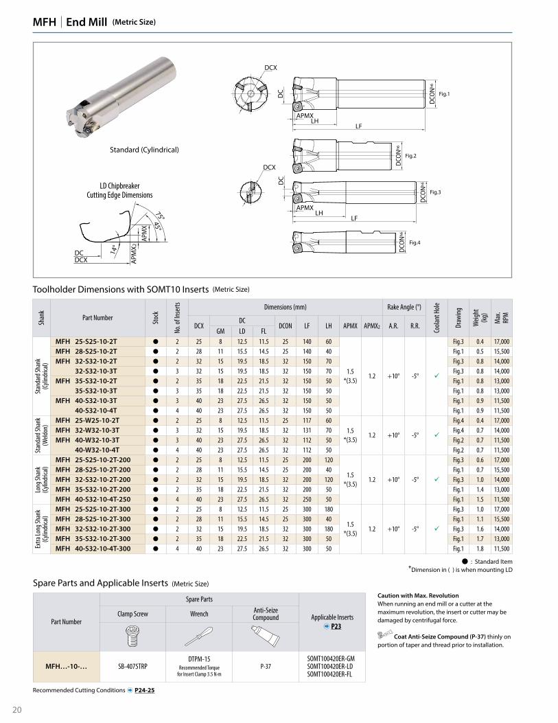
20
Toolholder Dimensions with SOMT10 Inserts (Metric Size)
Shan
k
Part Number Stoc
k
No. o
f Inse
rts Dimensions (mm) Rake Angle (°)
Coola
nt H
ole
Draw
ing
Weig
ht(kg
)
Max
.RP
M
DCXDC
DCON LF LH APMX APMX2 A.R. R.R.GM LD FL
Stan
dard
Shan
k(Cy
lindr
ical)
MFH 25-S25-10-2T Þ 2 25 8 12.5 11.5 25 140 60
1.5*(3.5)
1.2 +10° -5° �
Fig.3 0.4 17,000 MFH 28-S25-10-2T Þ 2 28 11 15.5 14.5 25 140 40 Fig.1 0.5 15,500 MFH 32-S32-10-2T Þ 2 32 15 19.5 18.5 32 150 70 Fig.3 0.8 14,000
32-S32-10-3T Þ 3 32 15 19.5 18.5 32 150 70 Fig.3 0.8 14,000 MFH 35-S32-10-2T Þ 2 35 18 22.5 21.5 32 150 50 Fig.1 0.8 13,000
35-S32-10-3T Þ 3 35 18 22.5 21.5 32 150 50 Fig.1 0.8 13,000 MFH 40-S32-10-3T Þ 3 40 23 27.5 26.5 32 150 50 Fig.1 0.9 11,500
40-S32-10-4T Þ 4 40 23 27.5 26.5 32 150 50 Fig.1 0.9 11,500
Stan
dard
Shan
k(W
eldon
) MFH 25-W25-10-2T Þ 2 25 8 12.5 11.5 25 117 601.5
*(3.5)1.2 +10° -5° �
Fig.4 0.4 17,000 MFH 32-W32-10-3T Þ 3 32 15 19.5 18.5 32 131 70 Fig.4 0.7 14,000 MFH 40-W32-10-3T Þ 3 40 23 27.5 26.5 32 112 50 Fig.2 0.7 11,500
40-W32-10-4T Þ 4 40 23 27.5 26.5 32 112 50 Fig.2 0.7 11,500
Long
Shan
k(Cy
lindr
ical)
MFH 25-S25-10-2T-200 Þ 2 25 8 12.5 11.5 25 200 120
1.5*(3.5)
1.2 +10° -5° �
Fig.3 0.6 17,000 MFH 28-S25-10-2T-200 Þ 2 28 11 15.5 14.5 25 200 40 Fig.1 0.7 15,500 MFH 32-S32-10-2T-200 Þ 2 32 15 19.5 18.5 32 200 120 Fig.3 1.0 14,000 MFH 35-S32-10-2T-200 Þ 2 35 18 22.5 21.5 32 200 50 Fig.1 1.4 13,000 MFH 40-S32-10-4T-250 Þ 4 40 23 27.5 26.5 32 250 50 Fig.1 1.5 11,500
Extra
Long
Shan
k(Cy
lindr
ical)
MFH 25-S25-10-2T-300 Þ 2 25 8 12.5 11.5 25 300 180
1.5*(3.5)
1.2 +10° -5° �
Fig.3 1.0 17,000MFH 28-S25-10-2T-300 Þ 2 28 11 15.5 14.5 25 300 40 Fig.1 1.1 15,500MFH 32-S32-10-2T-300 Þ 2 32 15 19.5 18.5 32 300 180 Fig.3 1.6 14,000MFH 35-S32-10-2T-300 Þ 2 35 18 22.5 21.5 32 300 50 Fig.1 1.7 13,000MFH 40-S32-10-4T-300 Þ 4 40 23 27.5 26.5 32 300 50 Fig.1 1.8 11,500
MFH End Mill (Metric Size)
Standard (Cylindrical)
14°
45°75°
LD ChipbreakerCutting Edge Dimensions
APM
X2AP
MX
DCDCX
Fig.1
Fig.2
Fig.3
Fig.4
APMX
APMX
LH
LH
LF
LF
DCO
Nh6
DCO
Nh6
DCO
Nh6
DCO
Nh6
DC
DC
DCX
DCX
Recommended Cutting Conditions � P24-25
Spare Parts and Applicable Inserts (Metric Size)
Part Number
Spare Parts
Applicable Inserts� P23
Clamp Screw Wrench Anti-SeizeCompound
MFH…-10-… SB-4075TRPDTPM-15
Recommended Torque for Insert Clamp 3.5 N·m
P-37SOMT100420ER-GMSOMT100420ER-LDSOMT100420ER-FL
Caution with Max. RevolutionWhen running an end mill or a cutter at the maximum revolution, the insert or cutter may be damaged by centrifugal force.
Coat Anti-Seize Compound (P-37) thinly on portion of taper and thread prior to installation.
Þ : Standard Item *Dimension in ( ) is when mounting LD

21
MFH End Mill (Metric Size)
DCO
Nh6
APMXLH
LF
DC
DCX
DCO
Nh6
APMXLH
LF
DCX
DC
Fig.1
Fig.2
16°
45°75°
DCDCX
LD ChipbreakerCutting Edge Dimensions
APM
X2AP
MX
Toolholder Dimensions with SOMT14 Inserts (Metric Size)
Part Number Stoc
k
No. o
f Inse
rts Dimensions (mm) Rake Angle (°)
Coola
nt H
ole
Draw
ing
Weig
ht(kg
)
Max
.RP
M
DCXDC
DCON LF LH APMX APMX2 A.R. R.R.GM LD FL
MFH 50-S42-14-3T Þ 3 50 27 33 32 42 150 50
2*(5)
2 +10°
-10° � Fig.1 1.4 8,800
MFH 63-S42-14-4T Þ 4 63 40 46 45 42 150 50 -10° � Fig.2 1.7 7,400
MFH 80-S42-14-5T Þ 5 80 57 63 62 42 150 50 -8° � Fig.2 2.3 6,400
Recommended Cutting Conditions � P24-25
Spare Parts and Applicable Inserts (Metric Size)
Part Number
Spare Parts
Applicable Inserts� P23
Clamp Screw Wrench Anti-SeizeCompound
MFH…-14-… SB-50120TRPTTP-20
Recommended Torque for Insert Clamp 4.5 N·m
P-37SOMT140520ER-GMSOMT140520ER-LDSOMT140514ER-FL
Caution with Max. RevolutionWhen running an end mill or a cutter at the maximum revolution, the insert or cutter may be damaged by centrifugal force.
Coat Anti-Seize Compound (P-37) thinly on portion of taper and thread prior to installation.
Þ : Standard Item *Dimension in ( ) is when mounting LD

22
MFH Modular End Mill (Metric Size)
Toolholder Dimensions
Part Number Stoc
k
No. o
f Inse
rts Dimensions (mm) Rake Angle (°)
Coola
nt H
ole
Max
.RP
M
DCXDC
DCSFMS DCON OAL LF CRKS H APMX APMX2 A.R. R.R.GM LD FL
MFH 25-M12-10-2T Þ 2 25 8 12.5 11.5 23 12.5 57 35 M12×P1.75 19
1.5*(3.5)
1.2 +10° -5° �
17,000
MFH 28-M12-10-2T Þ 2 28 11 15.5 14.5 23 12.5 57 35 M12×P1.75 19 15,500
MFH 32-M16-10-2T Þ 2 32 15 19.5 18.5 30 17 63 40 M16×P2.0 24 14,000
32-M16-10-3T Þ 3 32 15 19.5 18.5 30 17 63 40 M16×P2.0 24 14,000
MFH 35-M16-10-2T Þ 2 35 18 22.5 21.5 30 17 63 40 M16×P2.0 24 13,000
35-M16-10-3T Þ 3 35 18 22.5 21.5 30 17 63 40 M16×P2.0 24 13,000
MFH 40-M16-10-3T Þ 3 40 23 27.5 26.5 30 17 63 40 M16×P2.0 24 11,500
40-M16-10-4T Þ 4 40 23 27.5 26.5 30 17 63 40 M16×P2.0 24 11,500
APMX
OAL
LF
DCS
FMS
DC
DCO
N
CRKSDCXH
A-A Section
A
A
Recommended Cutting Conditions � P24-25
Spare Parts and Applicable Inserts
Part Number
Spare Parts
Applicable Inserts� P23
Clamp Screw Wrench Anti-SeizeCompound
MFH…-10-… SB-4075TRPDTPM-15
Recommended Torque for Insert Clamp 3.5 N·m
P-37SOMT100420ER-GMSOMT100420ER-LDSOMT100420ER-FL
Caution with Max. RevolutionWhen running an end mill or a cutter at the maximum revolution, the insert or cutter may be damaged by centrifugal force.
Coat Anti-Seize Compound (P-37) thinly on portion of taper and thread prior to installation.
14°
45°75°
LD ChipbreakerCutting Edge Dimensions
APM
X2AP
MX
DCDCX
Þ : Standard Item *Dimension in ( ) is when mounting LD

23
Usage Classification PCarbon Steel / Alloy Steel
Toolh
older
Refer
ence
Page
Mold Steel
: Roughing / 1st Choice
: Roughing / 2nd Choice
: Finishing / 1st Choice
: Finishing / 2nd Choice
MAustenitic Stainless Steel
Martensitic Stainless Steel
KGray Cast Iron
Nodular Cast Iron
SNi-base Heat Resistant Alloy
Titanium Alloy
H Hardened Materials
Insert Part NumberDimension (in) Angle
(°) MEGACOAT NANO CVD
IC S D1 BS RE AN PR1535 PR1525 PR1510 CA6535
General Purpose
SOMT 100420ER-GM 0.406 0.180 0.181 - 0.079 16° Þ Þ Þ Þ
P16
P22
SOMT 140520ER-GM 0.557 0.219 0.228 - 0.079 16° Þ Þ Þ Þ
Large D.O.C.
SOMT 100420ER-LD 0.411 0.180 0.181 0.035 0.079 16° Þ Þ Þ Þ
SOMT 140520ER-LD 0.581 0.219 0.228 0.063 0.079 16° Þ Þ Þ Þ
Wiper Edge
SOMT 100420ER-FL 0.411 0.180 0.181 0.055 0.079 16° Þ Þ Þ Þ
SOMT 140514ER-FL 0.574 0.219 0.228 0.122 0.055 16° Þ Þ Þ Þ
IC
D1
AN
S
RE
IC
AN
D1
SBS
RE
IC
AN
D1
SBS RE
MFH1000-W100-10-2TMFH25-S25-10-2T
MFH2000R ~ 3000R-10- TMFH050R ~ 080R-10- T
MFH1250-W125-10- TMFH32-S32-10- T
MFH . . -14- T
MFH1500-W150-10- TMFH40-S32-10- T
0.020
0.020 0.039 0.059 0.079
0.039
0.079
0.059
Feed Rate fz (ipt)
D.O
.C. (
in)
0.020
0.020 0.039 0.059 0.079
0.039
0.079
0.059
Feed Rate fz (ipt)
D.O
.C. (
in)
0.020
0.020 0.039 0.059 0.079
0.039
0.079
0.059
Feed Rate fz (ipt)
D.O
.C. (
in)
0.020
0.020 0.039 0.059 0.079
0.039
0.079
0.059
Feed Rate fz (ipt)
D.O
.C. (
in)
0.020
0.020 0.039 0.059 0.079
0.039
0.079
0.059
Feed Rate fz (ipt)
D.O
.C. (
in)
MFH Applicable Inserts
Cutting Performance (GM, FL Chipbreakers)
End Mill:Please refer to the application map above
LD Chipbreaker:MAX D.O.C. for LD chipbreaker is 0.197” (0.138” for SOMT10)Please refer to � P24-25 for feed rate
Face Mill:MAX feed rate (inches per tooth) fz = 0.079ipt
Þ : Standard Item

24
Chipb
reak
er
Workpiece
Holder Part Number and Feed Rate (fz: ipt) Recommended Insert Grade (Vc: sfm)
End Mill Feed Rates Face Mill Feed Rates MEGACOAT NANO CVD
MFH1000MFH25-
MFH1250MFH32-
MFH1500MFH40- MFH…R-10 MFH…-14 PR1535 PR1525 PR1510 CA6535
GM
Carbon Steel ��
0.020 - 0.032 - 0.0390.008 - 0.016 - 0.020
��
0.020 - 0.039 - 0.0590.012 - 0.028 - 0.039
��
0.020 - 0.047 - 0.0710.016 - 0.039 - 0.059
0.020 - 0.059 - 0.079390 - 590 - 820 390 - 590 - 820
- -
Alloy Steel ��
0.020 - 0.032 - 0.0390.008 - 0.016 - 0.020
��
0.020 - 0.039 - 0.0590.012 - 0.028 - 0.039
��
0.020 - 0.047 - 0.0710.016 - 0.039 - 0.059
0.020 - 0.059 - 0.079330 - 520 - 720 330 - 520 - 720
- -
Mold Steel(~40HRc)
��
0.020 - 0.028 - 0.0320.008 - 0.012 - 0.016
��
0.020 - 0.032 - 0.0470.012 - 0.024 - 0.032
��
0.020 - 0.039 - 0.0630.016 - 0.032 - 0.047
0.020 - 0.047 - 0.071260 - 460 - 590 260 - 460 - 590
- -
Mold Steel(40~50HRc)
��
0.006 - 0.012 - 0.0200.006 - 0.008 - 0.010
��
0.008 - 0.020 - 0.0320.008 - 0.012 - 0.018
��
0.008 - 0.024 - 0.0350.008 - 0.020 - 0.028
0.008 - 0.028 - 0.039200 - 330 - 430 200 - 330 - 430
- -
AusteniticStainless Steel
��
0.020 - 0.028 - 0.0320.008 - 0.012 - 0.016
��
0.020 - 0.032 - 0.0470.012 - 0.024 - 0.032
��
0.020 - 0.039 - 0.0630.016 - 0.032 - 0.047
0.020 - 0.047 - 0.071330 - 520 - 660 330 - 520 - 660
- -
MartensiticStainless Steel
��
0.020 - 0.028 - 0.0320.008 - 0.012 - 0.016
��
0.020 - 0.032 - 0.0470.012 - 0.024 - 0.032
��
0.020 - 0.039 - 0.0630.016 - 0.032 - 0.047
0.020 - 0.047 - 0.071490 - 660 - 820
- -590 - 790 - 980
Precipitation HardenedStainless Steel
��
0.020 - 0.028 - 0.0320.008 - 0.012 - 0.016
��
0.020 - 0.032 - 0.0470.012 - 0.024 - 0.032
��
0.020 - 0.039 - 0.0630.016 - 0.032 - 0.047
0.020 - 0.047 - 0.071300 - 390 - 490
- - -
Gray Cast Iron ��
0.020 - 0.032 - 0.0390.008 - 0.016 - 0.020
��
0.020 - 0.039 - 0.0590.012 - 0.028 - 0.039
��
0.020 - 0.047 - 0.0710.016 - 0.039 - 0.059
0.020 - 0.059 - 0.079 - -390 - 590 - 820
-
Nodular Cast Iron ��
0.020 - 0.028 - 0.0320.008 - 0.012 - 0.016
��
0.020 - 0.032 - 0.0470.012 - 0.024 - 0.032
��
0.020 - 0.039 - 0.0630.016 - 0.032 - 0.047
0.020 - 0.047 - 0.071 - -330 - 490 - 660
-
Ni-base Heat Resistant Alloy
��
0.008 - 0.016 - 0.0240.006 - 0.008 - 0.012
��
0.008 - 0.020 - 0.0350.008 - 0.016 - 0.024
��
0.008 - 0.024 - 0.0390.008 - 0.020 - 0.032
0.008 - 0.032 - 0.04770 - 100 - 160
- -70 - 100 - 160
Titanium Alloy ��
0.008 - 0.016 - 0.0240.006 - 0.008 - 0.012
��
0.008 - 0.020 - 0.0350.008 - 0.016 - 0.024
��
0.008 - 0.024 - 0.0390.008 - 0.020 - 0.032
0.008 - 0.032 - 0.047130 - 200 - 260
-100 - 160 - 230
-
LD
Carbon Steel ��
0.020 - 0.032 - 0.0390.002 - 0.004 - 0.008
��
0.020 - 0.039 - 0.0590.002 - 0.006 - 0.012
��
0.020 - 0.047 - 0.0710.002 - 0.008 - 0.012
��
0.020 - 0.059 - 0.0790.002 - 0.008 - 0.012
��
0.020 - 0.059 - 0.0790.002 - 0.008 - 0.016 390 - 590 - 820 390 - 590 - 820
- -
Alloy Steel ��
0.020 - 0.032 - 0.0390.002 - 0.004 - 0.008
��
0.020 - 0.039 - 0.0590.002~0.006~0.012
��
0.020 - 0.047 - 0.0710.002 - 0.008 - 0.012
��
0.020 - 0.059 - 0.0790.002 - 0.008 - 0.012
��
0.020 - 0.059 - 0.0790.002 - 0.008 - 0.016 330 - 520 - 720 330 - 520 - 720
- -
Mold Steel(~40HRc)
��
0.020 - 0.028 - 0.0320.002 - 0.003 - 0.006
��
0.020 - 0.032 - 0.0470.002 - 0.004 - 0.008
��
0.020 - 0.039 - 0.0630.002 - 0.006 - 0.008
��
0.020 - 0.047 - 0.0710.002 - 0.006 - 0.008
��
0.020 - 0.047 - 0.0710.002 - 0.006 - 0.012 260 - 460 - 590 260 - 460 - 590
- -
Mold Steel(40~50HRc)
��
0.008 - 0.012 - 0.0200.001 - 0.002 - 0.004
��
0.008 - 0.020 - 0.0320.001 - 0.003 - 0.006
��
0.008 - 0.024 - 0.0350.001 - 0.004 - 0.006
��
0.008 - 0.028 - 0.0390.001 - 0.004 - 0.006
��
0.008 - 0.028 - 0.0390.001 - 0.004 - 0.008 200 - 330 - 430 200 - 330 - 430
- -
AusteniticStainless Steel
��
0.020 - 0.028 - 0.0320.002 - 0.003 - 0.006
��
0.020 - 0.032 - 0.0470.002 - 0.004 - 0.008
��
0.020 - 0.039 - 0.0630.002 - 0.006 - 0.008
��
0.020 - 0.047 - 0.0710.002 - 0.006 - 0.008
��
0.020 - 0.047 - 0.0710.002 - 0.006 - 0.012 330 - 520 - 660 330 - 520 - 660
- -
MartensiticStainless Steel
��
0.020 - 0.028 - 0.0320.002 - 0.003 - 0.006
��
0.020 - 0.032 - 0.0470.002 - 0.004 - 0.008
��
0.020 - 0.039 - 0.0630.002 - 0.006 - 0.008
��
0.020 - 0.047 - 0.0710.002 - 0.006 - 0.008
��
0.020 - 0.047 - 0.0710.002 - 0.006 - 0.012 490 - 660 - 820
- -590 - 790 - 980
Precipitation HardenedStainless Steel
��
0.020 - 0.028 - 0.0320.002 - 0.003 - 0.006
��
0.020 - 0.032 - 0.0470.002 - 0.004 - 0.008
��
0.020 - 0.039 - 0.0630.002 - 0.006 - 0.008
��
0.020 - 0.047 - 0.0710.002 - 0.006 - 0.008
��
0.020 - 0.047 - 0.0710.002 - 0.006 - 0.012 300 - 390 - 490
- - -
Gray Cast Iron ��
0.020 - 0.032 - 0.0390.002 - 0.004 - 0.008
��
0.020 - 0.039 - 0.0590.002 - 0.006 - 0.012
��
0.020 - 0.047 - 0.0710.002 - 0.008 - 0.012
��
0.020 - 0.059 - 0.0790.002 - 0.008 - 0.012
��
0.020 - 0.059 - 0.0790.002 - 0.008 - 0.016
- -390 - 590 - 820
-
Nodular Cast Iron ��
0.020 - 0.028 - 0.0320.002 - 0.003 - 0.006
��
0.020 - 0.032 - 0.0470.002 - 0.004 - 0.008
��
0.020 - 0.039 - 0.0630.002 - 0.006 - 0.008
��
0.020 - 0.047 - 0.0710.002 - 0.006 - 0.008
��
0.020 - 0.047 - 0.0710.002 - 0.006 - 0.012
- -330 - 490 - 660
-
Ni-base Heat Resistant Alloy
��
0.008 - 0.016 - 0.0240.001 - 0.002 - 0.004
��
0.008 - 0.020 - 0.0350.001 - 0.003 - 0.006
��
0.008 - 0.024 - 0.0390.001 - 0.004 - 0.006
��
0.008 - 0.032 - 0.0470.001 - 0.004 - 0.006
��
0.008 - 0.032 - 0.0470.001 - 0.004 - 0.008 70 - 100 - 160
- -70 - 100 - 160
Titanium Alloy ��
0.008 - 0.016 - 0.0240.001 - 0.002 - 0.004
��
0.008 - 0.020 - 0.0350.001 - 0.003 - 0.006
��
0.008 - 0.024 - 0.0390.001 - 0.004 - 0.006
��
0.008 - 0.032 - 0.0470.001 - 0.004 - 0.006
��
0.008 - 0.032 - 0.0470.001 - 0.004 - 0.008 130 - 200 - 260
-100 - 160 - 230
-
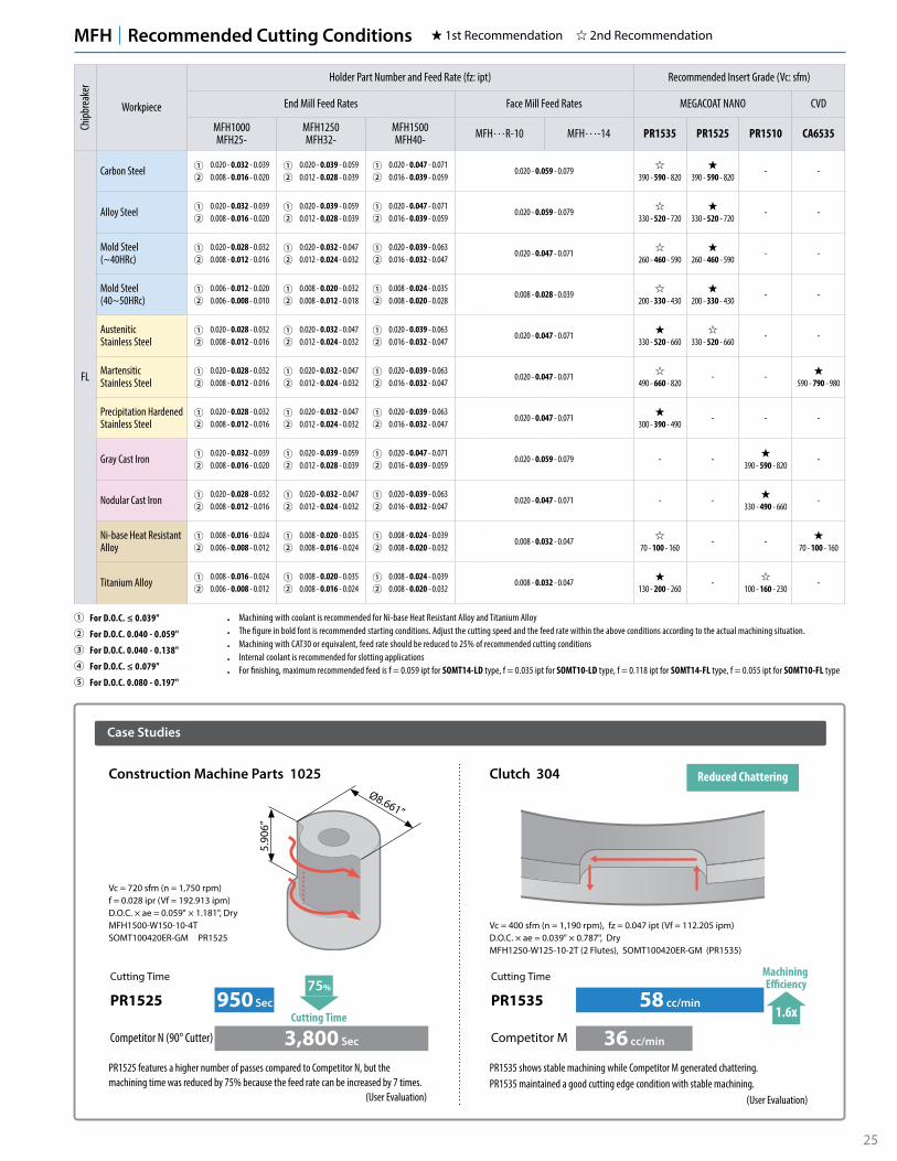
MFH Recommended Cutting Conditions 1st Recommendation 2nd Recommendation
• Machining with coolant is recommended for Ni-base Heat Resistant Alloy and Titanium Alloy• The figure in bold font is recommended starting conditions. Adjust the cutting speed and the feed rate within the above conditions according to the actual machining situation.• Machining with CAT30 or equivalent, feed rate should be reduced to 25% of recommended cutting conditions• Internal coolant is recommended for slotting applications• For finishing, maximum recommended feed is f = 0.059 ipt for SOMT14-LD type, f = 0.035 ipt for SOMT10-LD type, f = 0.118 ipt for SOMT14-FL type, f = 0.055 ipt for SOMT10-FL type
� For D.O.C. ≤ 0.039"
� For D.O.C. 0.040 - 0.059"
� For D.O.C. 0.040 - 0.138"
� For D.O.C. ≤ 0.079"
� For D.O.C. 0.080 - 0.197"
25
MFH Recommended Cutting Conditions 1st Recommendation 2nd Recommendation
• Machining with coolant is recommended for Ni-base Heat Resistant Alloy and Titanium Alloy• The figure in bold font is recommended starting conditions. Adjust the cutting speed and the feed rate within the above conditions according to the actual machining situation.• Machining with CAT30 or equivalent, feed rate should be reduced to 25% of recommended cutting conditions• Internal coolant is recommended for slotting applications• For finishing, maximum recommended feed is f = 0.059 ipt for SOMT14-LD type, f = 0.035 ipt for SOMT10-LD type, f = 0.118 ipt for SOMT14-FL type, f = 0.055 ipt for SOMT10-FL type
� For D.O.C. ≤ 0.039"
� For D.O.C. 0.040 - 0.059"
� For D.O.C. 0.040 - 0.138"
� For D.O.C. ≤ 0.079"
� For D.O.C. 0.080 - 0.197"
Chipb
reak
er
Workpiece
Holder Part Number and Feed Rate (fz: ipt) Recommended Insert Grade (Vc: sfm)
End Mill Feed Rates Face Mill Feed Rates MEGACOAT NANO CVD
MFH1000MFH25-
MFH1250MFH32-
MFH1500MFH40- MFH…R-10 MFH…-14 PR1535 PR1525 PR1510 CA6535
FL
Carbon Steel ��
0.020 - 0.032 - 0.0390.008 - 0.016 - 0.020
��
0.020 - 0.039 - 0.0590.012 - 0.028 - 0.039
��
0.020 - 0.047 - 0.0710.016 - 0.039 - 0.059
0.020 - 0.059 - 0.079390 - 590 - 820 390 - 590 - 820
- -
Alloy Steel ��
0.020 - 0.032 - 0.0390.008 - 0.016 - 0.020
��
0.020 - 0.039 - 0.0590.012 - 0.028 - 0.039
��
0.020 - 0.047 - 0.0710.016 - 0.039 - 0.059
0.020 - 0.059 - 0.079330 - 520 - 720 330 - 520 - 720
- -
Mold Steel(~40HRc)
��
0.020 - 0.028 - 0.0320.008 - 0.012 - 0.016
��
0.020 - 0.032 - 0.0470.012 - 0.024 - 0.032
��
0.020 - 0.039 - 0.0630.016 - 0.032 - 0.047
0.020 - 0.047 - 0.071260 - 460 - 590 260 - 460 - 590
- -
Mold Steel(40~50HRc)
��
0.006 - 0.012 - 0.0200.006 - 0.008 - 0.010
��
0.008 - 0.020 - 0.0320.008 - 0.012 - 0.018
��
0.008 - 0.024 - 0.0350.008 - 0.020 - 0.028
0.008 - 0.028 - 0.039200 - 330 - 430 200 - 330 - 430
- -
AusteniticStainless Steel
��
0.020 - 0.028 - 0.0320.008 - 0.012 - 0.016
��
0.020 - 0.032 - 0.0470.012 - 0.024 - 0.032
��
0.020 - 0.039 - 0.0630.016 - 0.032 - 0.047
0.020 - 0.047 - 0.071330 - 520 - 660 330 - 520 - 660
- -
MartensiticStainless Steel
��
0.020 - 0.028 - 0.0320.008 - 0.012 - 0.016
��
0.020 - 0.032 - 0.0470.012 - 0.024 - 0.032
��
0.020 - 0.039 - 0.0630.016 - 0.032 - 0.047
0.020 - 0.047 - 0.071490 - 660 - 820
- -590 - 790 - 980
Precipitation HardenedStainless Steel
��
0.020 - 0.028 - 0.0320.008 - 0.012 - 0.016
��
0.020 - 0.032 - 0.0470.012 - 0.024 - 0.032
��
0.020 - 0.039 - 0.0630.016 - 0.032 - 0.047
0.020 - 0.047 - 0.071300 - 390 - 490
- - -
Gray Cast Iron ��
0.020 - 0.032 - 0.0390.008 - 0.016 - 0.020
��
0.020 - 0.039 - 0.0590.012 - 0.028 - 0.039
��
0.020 - 0.047 - 0.0710.016 - 0.039 - 0.059
0.020 - 0.059 - 0.079 - -390 - 590 - 820
-
Nodular Cast Iron ��
0.020 - 0.028 - 0.0320.008 - 0.012 - 0.016
��
0.020 - 0.032 - 0.0470.012 - 0.024 - 0.032
��
0.020 - 0.039 - 0.0630.016 - 0.032 - 0.047
0.020 - 0.047 - 0.071 - -330 - 490 - 660
-
Ni-base Heat Resistant Alloy
��
0.008 - 0.016 - 0.0240.006 - 0.008 - 0.012
��
0.008 - 0.020 - 0.0350.008 - 0.016 - 0.024
��
0.008 - 0.024 - 0.0390.008 - 0.020 - 0.032
0.008 - 0.032 - 0.04770 - 100 - 160
- -70 - 100 - 160
Titanium Alloy ��
0.008 - 0.016 - 0.0240.006 - 0.008 - 0.012
��
0.008 - 0.020 - 0.0350.008 - 0.016 - 0.024
��
0.008 - 0.024 - 0.0390.008 - 0.020 - 0.032
0.008 - 0.032 - 0.047130 - 200 - 260
-100 - 160 - 230
-
Case Studies
PR1535 shows stable machining while Competitor M generated chattering.PR1535 maintained a good cutting edge condition with stable machining.
(User Evaluation)
PR1525 features a higher number of passes compared to Competitor N, but the machining time was reduced by 75% because the feed rate can be increased by 7 times.
(User Evaluation)
Vc = 400 sfm (n = 1,190 rpm), fz = 0.047 ipt (Vf = 112.205 ipm) D.O.C. × ae = 0.039" × 0.787", DryMFH1250-W125-10-2T (2 Flutes), SOMT100420ER-GM (PR1535)
Clutch 304
Cutting Time
1.6x
Machining E�ciency
58 cc/min
36 cc/min
PR1535
Competitor M
Cutting Time75%
Cutting Time950 Sec
3,800 Sec
PR1525
Competitor N (90° Cutter)
Reduced Chattering
Vc = 720 sfm (n = 1,750 rpm)f = 0.028 ipr (Vf = 192.913 ipm)D.O.C. × ae = 0.059" × 1.181", DryMFH1500-W150-10-4TSOMT100420ER-GM PR1525
Construction Machine Parts 1025Ø8.661”
5.90
6”

26
BT Arbor (for Exchangeable Head / Two Face Contact)
Coolant Hole (Center Through System)
Attachment
Gage Line (Gage Face)
CRKS
DCON
WS
BD
LF
G
Applicable End Mill Applicable Arbor
Holder Dimensions
Part Number StockDimensions (mm)
Coolant HoleArbor
(Two Face Clamping)Applicable End Mill (Head)
L BD DCONWS CRKS CCMS
BT30K- M08-45 ß 45 14.7 8.5 M8×P1.25
�
BT30 MFH..-M08-..
M10-45 ß 45 18.7 10.5 M10×P1.5 BT30 MFH..-M10-..
M12-45 ß 45 23 12.5 M12×P1.75 BT30 MFH..-M12-..
BT40K- M08-55 ß 55 14.7 8.5 M8×P1.25
�
BT40 MFH..-M08-..
M10-60 ß 60 18.7 10.5 M10×P1.5 BT40 MFH..-M10-..
M12-55 ß 55 23 12.5 M12×P1.75 BT40 MFH..-M12-..
M16-65 ß 65 30 17 M16×P2.0 BT40 MFH..-M16-..
ß : World Express (Shipping: 7-10 Business Days)
Arbor Identification System
BT30 K M12 45- -Arbor Size Two-Face
Clamping SpindleThread Size
for ClampingLength from
the Gage
Actual End Mill Depth (BT Arbor Metric)
LF
DC
CRKS
ArborPart Number
Applicable End Mill Actual End Mill Depth (mm)
Part NumberCutting Dia. (mm) Dimension (mm)
LUXDC LF
BT30K- M08-45
...16-M08-... Ø16 25 31.8
...17-M08-... Ø17 25 33.2
...18-M08-... Ø18 25 34.2
M10-45...20-M10-... Ø20 30 36.8
...22-M10-... Ø22 30 39.2
M12-45...25-M12-... Ø25 35 42.8
...28-M12-... Ø28 35 45.5
BT40K- M08-55
...16-M08-... Ø16 25 31.7
...17-M08-... Ø17 25 33.2
...18-M08-... Ø18 25 34.3
M10-60...20-M10-... Ø20 30 38.7
...22-M10-... Ø22 30 44.5
M12-55...25-M12-... Ø25 35 44.6
...28-M12-... Ø28 35 47.6
M16-65
...32-M16-... Ø32 40 51.2
...35-M16-... Ø35 40 60.2
...40-M16-... Ø40 40 64
27
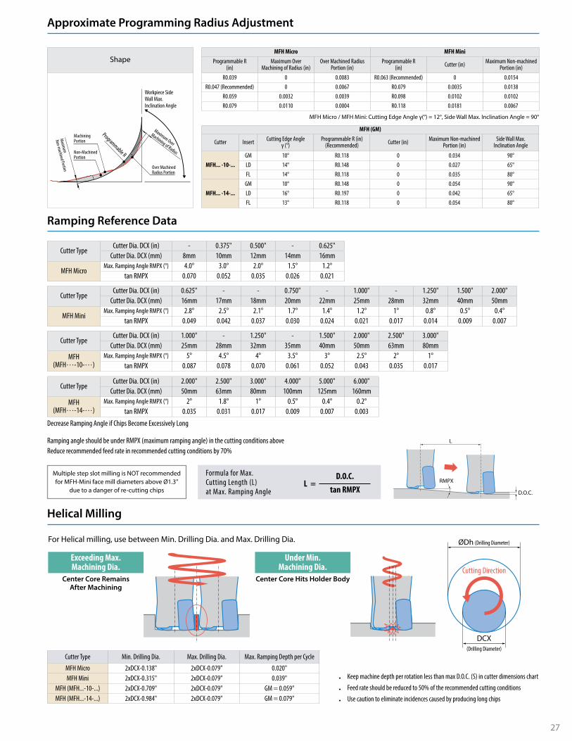
Approximate Programming Radius Adjustment
Ramping Reference Data
Helical Milling
Shape
Maximum Over
Machining of Radius
Over Machined Radius Portion
Programmable R
Machining Portion
Non-Machined Portion
Maximum
Non-machined Portion
Workpiece Side Wall Max. Inclination Angle
MFH Micro MFH MiniProgrammable R
(in)Maximum Over
Machining of Radius (in)Over Machined Radius
Portion (in)Programmable R
(in) Cutter (in) Maximum Non-machined Portion (in)
R0.039 0 0.0083 R0.063 (Recommended) 0 0.0154R0.047 (Recommended) 0 0.0067 R0.079 0.0035 0.0138
R0.059 0.0032 0.0039 R0.098 0.0102 0.0102R0.079 0.0110 0.0004 R0.118 0.0181 0.0067
MFH (GM)
Cutter Insert Cutting Edge Angleγ (°)
Programmable R (in)(Recommended) Cutter (in) Maximum Non-machined
Portion (in)Side Wall Max.
Inclination Angle
MFH... -10-... GM 10° R0.118 0 0.034 90°LD 14° R0.148 0 0.027 65°FL 14° R0.118 0 0.035 80°
MFH... -14-... GM 10° R0.148 0 0.054 90°LD 16° R0.197 0 0.042 65°FL 13° R0.118 0 0.054 80°
MFH Micro / MFH Mini: Cutting Edge Angle γ(°) = 12°, Side Wall Max. Inclination Angle = 90°
Ramping angle should be under RMPX (maximum ramping angle) in the cutting conditions aboveReduce recommended feed rate in recommended cutting conditions by 70%
L
D.O.C.
RMPXMultiple step slot milling is NOT recommended for MFH-Mini face mill diameters above Ø1.3"
due to a danger of re-cutting chips
Formula for Max.Cutting Length (L)at Max. Ramping Angle
D.O.C.tan RMPX
L =
Decrease Ramping Angle if Chips Become Excessively Long
Cutter TypeCutter Dia. DCX (in) 2.000" 2.500" 3.000" 4.000" 5.000" 6.000"
Cutter Dia. DCX (mm) 50mm 63mm 80mm 100mm 125mm 160mmMFH
(MFH…-14-…)Max. Ramping Angle RMPX (°) 2° 1.8° 1° 0.5° 0.4° 0.2°
tan RMPX 0.035 0.031 0.017 0.009 0.007 0.003
Cutter TypeCutter Dia. DCX (in) 1.000" - 1.250" - 1.500" 2.000" 2.500" 3.000"
Cutter Dia. DCX (mm) 25mm 28mm 32mm 35mm 40mm 50mm 63mm 80mmMFH
(MFH…-10-…)Max. Ramping Angle RMPX (°) 5° 4.5° 4° 3.5° 3° 2.5° 2° 1°
tan RMPX 0.087 0.078 0.070 0.061 0.052 0.043 0.035 0.017
Cutter TypeCutter Dia. DCX (in) 0.625" - - 0.750" - 1.000" - 1.250" 1.500" 2.000"
Cutter Dia. DCX (mm) 16mm 17mm 18mm 20mm 22mm 25mm 28mm 32mm 40mm 50mm
MFH MiniMax. Ramping Angle RMPX (°) 2.8° 2.5° 2.1° 1.7° 1.4° 1.2° 1° 0.8° 0.5° 0.4°
tan RMPX 0.049 0.042 0.037 0.030 0.024 0.021 0.017 0.014 0.009 0.007
Cutter TypeCutter Dia. DCX (in) - 0.375" 0.500" - 0.625"
Cutter Dia. DCX (mm) 8mm 10mm 12mm 14mm 16mm
MFH MicroMax. Ramping Angle RMPX (°) 4.0° 3.0° 2.0° 1.5° 1.2°
tan RMPX 0.070 0.052 0.035 0.026 0.021
• Keep machine depth per rotation less than max D.O.C. (S) in cutter dimensions chart
• Feed rate should be reduced to 50% of the recommended cutting conditions
• Use caution to eliminate incidences caused by producing long chips
Exceeding Max.Machining Dia.
Center Core RemainsAfter Machining
Under Min.Machining Dia.
Center Core Hits Holder Body
ØDh (Drilling Diameter)
Cutting Direction
DCX(Drilling Diameter)
Cutter Type Min. Drilling Dia. Max. Drilling Dia. Max. Ramping Depth per Cycle
MFH Micro 2xDCX-0.138" 2xDCX-0.079" 0.020"MFH Mini 2xDCX-0.315" 2xDCX-0.079" 0.039"
MFH (MFH...-10-...) 2xDCX-0.709" 2xDCX-0.079" GM = 0.059"MFH (MFH...-14-...) 2xDCX-0.984" 2xDCX-0.079" GM = 0.079"
For Helical milling, use between Min. Drilling Dia. and Max. Drilling Dia.

KYOCERA Precision Tools, Inc.102 Industrial Park RoadHendersonville, NC 28792Customer Service | 800.823.7284 - Option 1Technical Support | 800.823.7284 - Option 2
W | Official Website | www.kyoceraprecisiontools.comW | Distributor Website | http://mykpti.kyocera.comE | [email protected]
©KYOCERA Precision Tools, Inc.10/19
[Drilling Depth] See Max. Drilling Depth (Pd) in the above cutting conditions
Traversing after Drilling
It is recommended to reduce feed by 25% of recommendation on Page 24-25 until Center Core is removed
Axial feed rate recommendation per revolution is 0.008 ipr while drilling
Insert Ramping Contouring(Rising Wall Angle) Plunging Helical Milling Pocketing
GM � � (90°) � � �
LD � Limit (65°) × × ×
FL � Limit (80°) × × ×
Some applications are not available depending on chipbreaker.For FL and LD type, there is a limit of rising wall angle during contouring.
ae Cutter Type Insert Maximum Width of Cut (ae)MFH Micro LPGT01... 0.067"MFH Mini LOGU01... 0.138"
MFH (MFH...-10-...) SOMT10... 0.315"MFH (MFH...-14-...) SOMT14... 0.453"
Cutter Type Max. Drilling Depth(Pd)
Min. Cutting Length (X)for Flat Bottom Surface
MFH Micro 0.020" DCX-0.138"MFH Mini 0.039" DCX-0.354"
Cutter TypeGM LD FL
Max. Drilling Depth(Pd)
Min. Cutting Length (X)for Flat Bottom Surface
Max. Drilling Depth(Pd)
Min. Cutting Length (X)for Flat Bottom Surface
Max. Drilling Depth(Pd)
Min. Cutting Length (X)for Flat Bottom Surface
MFH (MFH...-10-...) 0.059" DCX-0.709" 0.059" DCX-0.551" 0.059" DCX-0.591"MFH (MFH...-14-...) 0.079" DCX-0.945" 0.079" DCX-0.709" 0.079" DCX-0.748"
LD and FL chipbreakers are not available for plungingReduce feed rate to fz ≤ 0.008ipt when plunging
Drilling
Plunging
3D Machining
Unit: inch
X
Center Core DCX
Pd
GM chipbreaker is available for all applications.
Face Milling & Shouldering
Slotting Ramping Helical Milling Pocketing Contouring


![HORIZONTAL MACHINING CENTERProgrammable Data Input(G10) Provided Manual Jog Feed : Rapid, Jog Feed, Handle 0~5,000mm/min[197 ipm] Manual Handle Feed-rate x1, x10, x100 F initial value](https://static.fdocuments.us/doc/165x107/61491ea69241b00fbd675a72/horizontal-machining-center-programmable-data-inputg10-provided-manual-jog-feed.jpg)