MF3331 Planter Downforce Technology for Uniform Seeding Depth · the gauge wheel mustache pin with...
8
Biological and Agricultural Engineering Kansas State University Agricultural Experiment Station and Cooperative Extension Service Static Downforce System Proper planting at target depth places seeds in the available moisture zone and provides good seed-to-soil contact for even germination and emergence. Given appropriate planting time and target depth where right moisture exists, seeds placed shallower or deeper than target depths have exhibited faster or delayed emergence, respectively, and at times, inadequate root development. Seeds planted deeper than expected/ optimal planting depth could result in decreased/ delayed emergence and this is a potential cause of poor crop development (Nafziger, 2009), all of which can result in a reduction in grain yield from 6 to 22 percent (Carter et al., 1992). Consistent seed depth is a key component because uniform seeding depths result in more uniform final plant population, proper nodal and brace root development, and can lead to higher yields. Appropriate load on an individual row unit trans- ferred from the toolbar, referred to as downforce, is critical to achieving uniform and consistent seeding depth. e planter gauge wheel arm travel is set to permit the opening discs to reach the target seeding depth during planting. Traditionally, the weight of the row unit along with a fixed additional load or force derived from a mechanical spring system (Figure 1) permits adjustment of spring tension, providing the neces- sary load for proper functioning of the opening discs, gauge wheels, and closing wheels. e available load or downforce is used by three key components in the following ways (Figure 2): 1. opening discs to create a seed furrow in the soil at a target depth (F O ); 2. provide sufficient loading on the gauge wheels, hereafter referred as gauge wheel load (F G ), to maintain uniform contact with the soil surface during field operation; and Planter Downforce Technology for Uniform Seeding Depth Ajay Sharda, John Fulton, Sylvester Badua, Terry Griffin, Ignacio Ciampitti, Lucas Haag Figure 2. Planter downforce action on individual row unit components. Total downforce (F D ) is sum of row unit load and applied downforce. Figure 1. Mechanical spring (within red box) for downforce control. FG = (Gauge Wheel Load) = FD - FC - FO Total Downforce on Row Unit (FD) = 350 lbs Reaction Force acting on the Opening Discs (FO) = 175 lbs Reaction Force acting on the Closing Wheels (FC) = 50 lbs Reaction Force acting on the Gauge Wheels (FG) = 125 lbs Ground Surface Gauge Wheel Load (GWL) Furrow Depth
Transcript of MF3331 Planter Downforce Technology for Uniform Seeding Depth · the gauge wheel mustache pin with...

Biological and Agricultural Engineering
Kansas State University Agricultural Experiment Station and Cooperative Extension Service
Static Downforce SystemProper planting at target depth places seeds in the
available moisture zone and provides good seed-to-soil contact for even germination and emergence. Given appropriate planting time and target depth where right moisture exists, seeds placed shallower or deeper than target depths have exhibited faster or delayed emergence, respectively, and at times, inadequate root development. Seeds planted deeper than expected/optimal planting depth could result in decreased/delayed emergence and this is a potential cause of poor crop development (Nafziger, 2009), all of which can result in a reduction in grain yield from 6 to 22 percent (Carter et al., 1992). Consistent seed depth is a key component because uniform seeding depths result in more uniform final plant population, proper nodal and brace root development, and can lead to higher yields. Appropriate load on an individual row unit trans-ferred from the toolbar, referred to as downforce, is critical to achieving uniform and consistent seeding depth.
The planter gauge wheel arm travel is set to permit the opening discs to reach the target seeding depth
during planting. Traditionally, the weight of the row unit along with a fixed additional load or force derived from a mechanical spring system (Figure 1) permits adjustment of spring tension, providing the neces-sary load for proper functioning of the opening discs, gauge wheels, and closing wheels. The available load or downforce is used by three key components in the following ways (Figure 2):
1. opening discs to create a seed furrow in the soil at a target depth (FO);
2. provide sufficient loading on the gauge wheels, hereafter referred as gauge wheel load (FG), to maintain uniform contact with the soil surface during field operation; and
Planter Downforce Technology for Uniform Seeding Depth
Ajay Sharda, John Fulton, Sylvester Badua, Terry Griffin, Ignacio Ciampitti, Lucas Haag
Figure 2. Planter downforce action on individual row unit components. Total downforce (FD) is sum of row unit load and applied downforce.
Figure 1. Mechanical spring (within red box) for downforce control.
FG = (Gauge Wheel Load) = FD - FC - FO
Total Downforce on Row Unit (FD) = 350 lbs
Reaction Force acting on the Opening Discs (FO) = 175 lbs
Reaction Force acting on the Closing Wheels (FC) = 50 lbs
Reaction Force acting on the Gauge Wheels (FG) = 125 lbs
Ground Surface
Gauge WheelLoad (GWL)
Furrow Depth
2 Precision Ag
Kansas State University Agricultural Experiment Station and Cooperative Extension Service
3. maintain the closing wheels in the proper working position (FC) to close the furrow.
Gauge wheel load is also commonly referred to as “margin.” The target load on a gauge wheel is also called “margin” because this the additional load avail-able and any proportion of it can be utilized by the opening discs as needed without compromising seed depth. The gauge wheels are responsible for main-taining the target seeding depth. Therefore, sufficient gauge wheel load is required so the planter compo-nents remain in contact with the soil while giving the opening disc adequate amount of load to penetrate the soil to create the furrow.
During field operation, the planter is typically set up during the initial passer within the field. During this process, seed depth and possibly spacing are evalu-ated to ensure proper setup for specific field conditions. A person will qualitatively assess gauge wheel load to complete the setup. Once the planter is set, oper-ators usually do not repeatedly check planting depth and presume the setup is appropriate for within the entire field as well as field-to-field operation. However, within a field soil texture and moisture, and machinery management, i.e. planting speed, frequently vary, which may alter the opening disc load requirements and overall net gauge wheel load.
Both disc load and gauge wheel load are essential to achieve uniform planting depth. The static down-force systems using mechanical springs do not provide operators any feedback via an in-cab display regarding the effect of varying soil conditions or planting speed on static spring downforce adjustments that might be
warranted when moving across the field. For example:
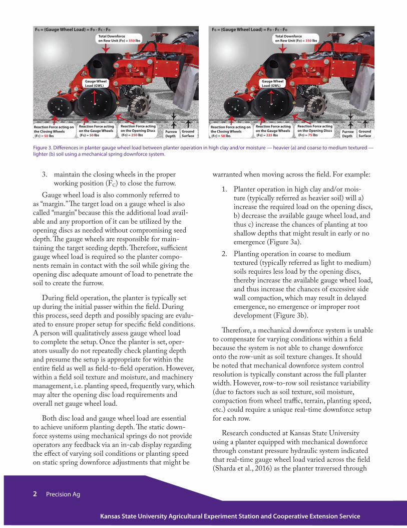
1. Planter operation in high clay and/or mois-ture (typically referred as heavier soil) will a) increase the required load on the opening discs, b) decrease the available gauge wheel load, and thus c) increase the chances of planting at too shallow depths that might result in early or no emergence (Figure 3a).
2. Planting operation in coarse to medium textured (typically referred as light to medium) soils requires less load by the opening discs, thereby increase the available gauge wheel load, and thus increase the chances of excessive side wall compaction, which may result in delayed emergence, no emergence or improper root development (Figure 3b).
Therefore, a mechanical downforce system is unable to compensate for varying conditions within a field because the system is not able to change downforce onto the row-unit as soil texture changes. It should be noted that mechanical downforce system control resolution is typically constant across the full planter width. However, row-to-row soil resistance variability (due to factors such as soil texture, soil moisture, compaction from wheel traffic, terrain, planting speed, etc.) could require a unique real-time downforce setup for each row.
Research conducted at Kansas State University using a planter equipped with mechanical downforce through constant pressure hydraulic system indicated that real-time gauge wheel load varied across the field (Sharda et al., 2016) as the planter traversed through
Figure 3. Differences in planter gauge wheel load between planter operation in high clay and/or moisture — heavier (a) and coarse to medium textured — lighter (b) soil using a mechanical spring downforce system.
FG = (Gauge Wheel Load) = FD - FC - FO
Total Downforce on Row Unit (FD) = 350 lbs
Reaction Force acting on the Opening Discs (FO) = 250 lbs
Reaction Force acting on the Closing Wheels (FC) = 50 lbs
Reaction Force acting on the Gauge Wheels (FG) = 50 lbs
Ground Surface
Gauge WheelLoad (GWL)
Furrow Depth
FG = (Gauge Wheel Load) = FD - FC - FO
Total Downforce on Row Unit (FD) = 350 lbs
Reaction Force acting on the Opening Discs (FO) = 75 lbs
Reaction Force acting on the Closing Wheels (FC) = 50 lbs
Reaction Force acting on the Gauge Wheels (FG) = 225 lbs
Ground Surface
Gauge WheelLoad (GWL)
Furrow Depth
3Precision Ag
Kansas State University Agricultural Experiment Station and Cooperative Extension Service
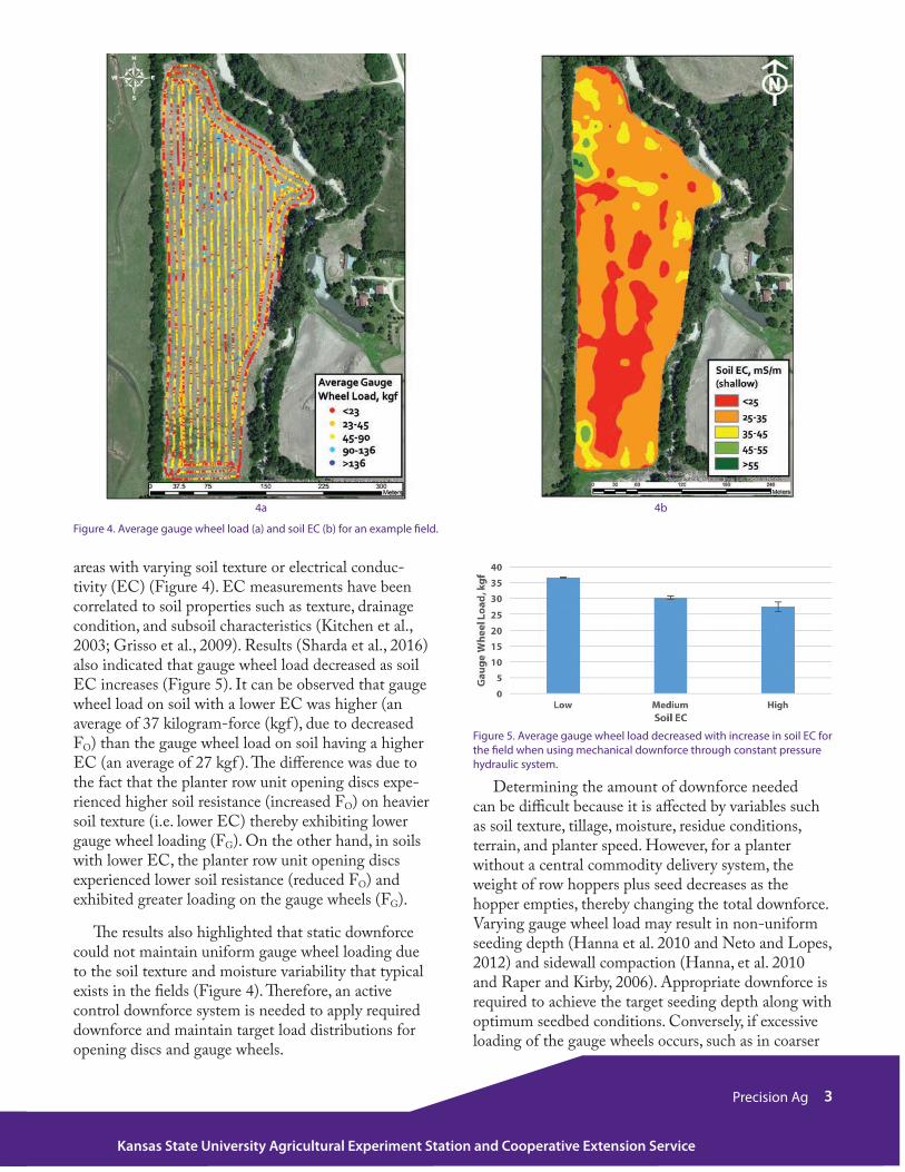
Figure 4. Average gauge wheel load (a) and soil EC (b) for an example field.
Figure 5. Average gauge wheel load decreased with increase in soil EC for the field when using mechanical downforce through constant pressure hydraulic system.
areas with varying soil texture or electrical conduc-tivity (EC) (Figure 4). EC measurements have been correlated to soil properties such as texture, drainage condition, and subsoil characteristics (Kitchen et al., 2003; Grisso et al., 2009). Results (Sharda et al., 2016) also indicated that gauge wheel load decreased as soil EC increases (Figure 5). It can be observed that gauge wheel load on soil with a lower EC was higher (an average of 37 kilogram-force (kgf ), due to decreased FO) than the gauge wheel load on soil having a higher EC (an average of 27 kgf ). The difference was due to the fact that the planter row unit opening discs expe-rienced higher soil resistance (increased FO) on heavier soil texture (i.e. lower EC) thereby exhibiting lower gauge wheel loading (FG). On the other hand, in soils with lower EC, the planter row unit opening discs experienced lower soil resistance (reduced FO) and exhibited greater loading on the gauge wheels (FG).
The results also highlighted that static downforce could not maintain uniform gauge wheel loading due to the soil texture and moisture variability that typical exists in the fields (Figure 4). Therefore, an active control downforce system is needed to apply required downforce and maintain target load distributions for opening discs and gauge wheels.
4a 4b
Determining the amount of downforce needed can be difficult because it is affected by variables such as soil texture, tillage, moisture, residue conditions, terrain, and planter speed. However, for a planter without a central commodity delivery system, the weight of row hoppers plus seed decreases as the hopper empties, thereby changing the total downforce. Varying gauge wheel load may result in non-uniform seeding depth (Hanna et al. 2010 and Neto and Lopes, 2012) and sidewall compaction (Hanna, et al. 2010 and Raper and Kirby, 2006). Appropriate downforce is required to achieve the target seeding depth along with optimum seedbed conditions. Conversely, if excessive loading of the gauge wheels occurs, such as in coarser
4 Precision Ag
Kansas State University Agricultural Experiment Station and Cooperative Extension Service
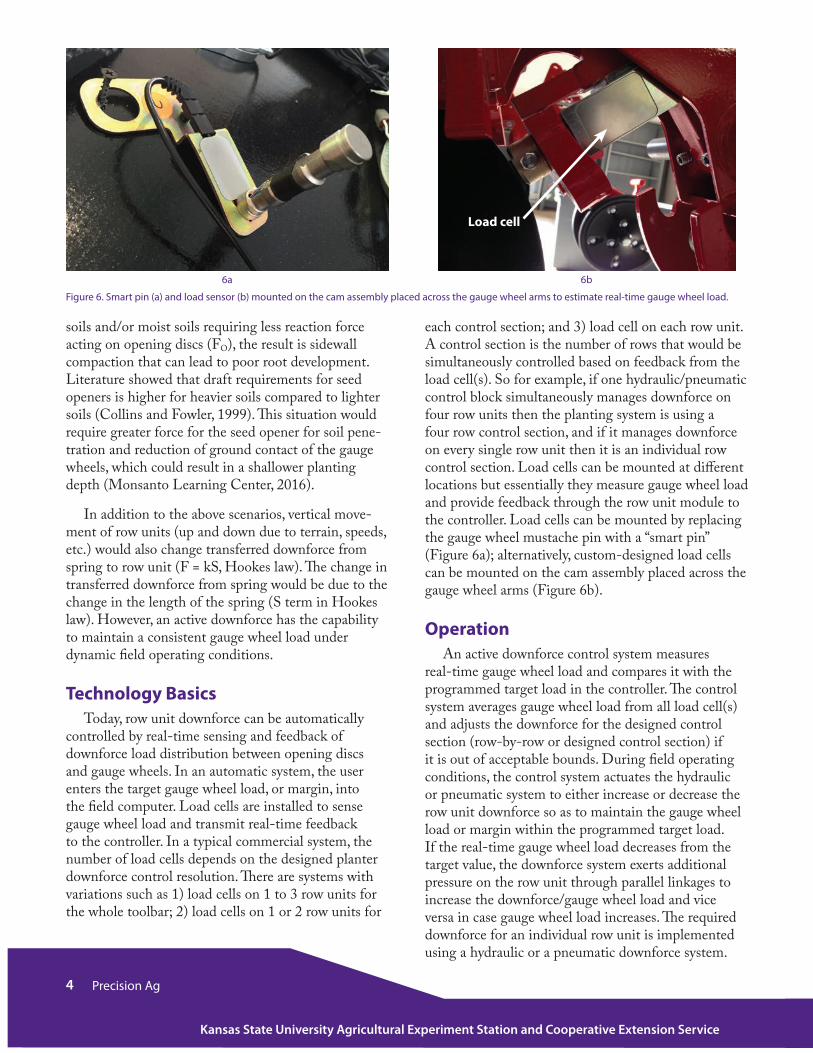
each control section; and 3) load cell on each row unit. A control section is the number of rows that would be simultaneously controlled based on feedback from the load cell(s). So for example, if one hydraulic/pneumatic control block simultaneously manages downforce on four row units then the planting system is using a four row control section, and if it manages downforce on every single row unit then it is an individual row control section. Load cells can be mounted at different locations but essentially they measure gauge wheel load and provide feedback through the row unit module to the controller. Load cells can be mounted by replacing the gauge wheel mustache pin with a “smart pin” (Figure 6a); alternatively, custom-designed load cells can be mounted on the cam assembly placed across the gauge wheel arms (Figure 6b).
Operation An active downforce control system measures
real-time gauge wheel load and compares it with the programmed target load in the controller. The control system averages gauge wheel load from all load cell(s) and adjusts the downforce for the designed control section (row-by-row or designed control section) if it is out of acceptable bounds. During field operating conditions, the control system actuates the hydraulic or pneumatic system to either increase or decrease the row unit downforce so as to maintain the gauge wheel load or margin within the programmed target load. If the real-time gauge wheel load decreases from the target value, the downforce system exerts additional pressure on the row unit through parallel linkages to increase the downforce/gauge wheel load and vice versa in case gauge wheel load increases. The required downforce for an individual row unit is implemented using a hydraulic or a pneumatic downforce system.
soils and/or moist soils requiring less reaction force acting on opening discs (FO), the result is sidewall compaction that can lead to poor root development. Literature showed that draft requirements for seed openers is higher for heavier soils compared to lighter soils (Collins and Fowler, 1999). This situation would require greater force for the seed opener for soil pene-tration and reduction of ground contact of the gauge wheels, which could result in a shallower planting depth (Monsanto Learning Center, 2016).
In addition to the above scenarios, vertical move-ment of row units (up and down due to terrain, speeds, etc.) would also change transferred downforce from spring to row unit (F = kS, Hookes law). The change in transferred downforce from spring would be due to the change in the length of the spring (S term in Hookes law). However, an active downforce has the capability to maintain a consistent gauge wheel load under dynamic field operating conditions.
Technology BasicsToday, row unit downforce can be automatically
controlled by real-time sensing and feedback of downforce load distribution between opening discs and gauge wheels. In an automatic system, the user enters the target gauge wheel load, or margin, into the field computer. Load cells are installed to sense gauge wheel load and transmit real-time feedback to the controller. In a typical commercial system, the number of load cells depends on the designed planter downforce control resolution. There are systems with variations such as 1) load cells on 1 to 3 row units for the whole toolbar; 2) load cells on 1 or 2 row units for
Figure 6. Smart pin (a) and load sensor (b) mounted on the cam assembly placed across the gauge wheel arms to estimate real-time gauge wheel load.
6a 6b
Load cell

5Precision Ag
Kansas State University Agricultural Experiment Station and Cooperative Extension Service
Figure 7. Example of pneumatic (a) and hydraulic (b) downforce technologies.
7a 7b
A commercial pneumatic type downforce system uses airbags or liftbags inflated by a hydraulically driven compressor to automatically control real-time downforce. Currently available downforce technology of this type includes the John Deere Seedstar XP, AirForce by Precision Planting and Great Plains (Figure 7a). On the other hand, the hydraulic down-force systems replace the mechanical springs or air bags with a hydraulic cylinder(s) to automatically control the downforce. The hydraulic system to control downforce on individual row units is available for Case IH, Kinze, Horsch, John Deere, and most other planter models (Figure 7b).
Some downforce systems, such as DAWN Equip-ment’s hydraulic RFX system, implement instanta-neous adjustments based on soil conditions by moni-toring the row-unit using an X-Sense fluid coupling down pressure sensor. The sensor filters out mechan-ical vibration and noise created by planter gauge to make an accurate downforce adjustment. Typically, a hydraulic downforce system reacts quicker than the pneumatic system.
BenefitsThe active downforce system provides several tech-
nological benefits including:
1. Maintains planting depth uniformity as field conditions vary, such as terrain and soil texture and moisture.
2. Automatically maintains the optimum gauge wheel load that ensures accurate seed placement without creating side-wall compaction.
3. Greater control resolution to apply variable downforce with changing field operating condi-tions.
4. Minimize row unit bounce and vibration as terrain and field conditions (e.g. rocks, clods, etc.) are encountered during planting.
5. Adjustment of applied downforce or margin from the cab to meet field conditions.
6. Ability to collect as-planted data for verifica-tion and identification of in-field variability (Figure 8).
Figure 8. Example of as-planted data showing spatial gauge wheel load variability. Regions in blue, orange and red indicate planting conditions where seed may not be placed at target depth.
6 Precision Ag
Kansas State University Agricultural Experiment Station and Cooperative Extension Service
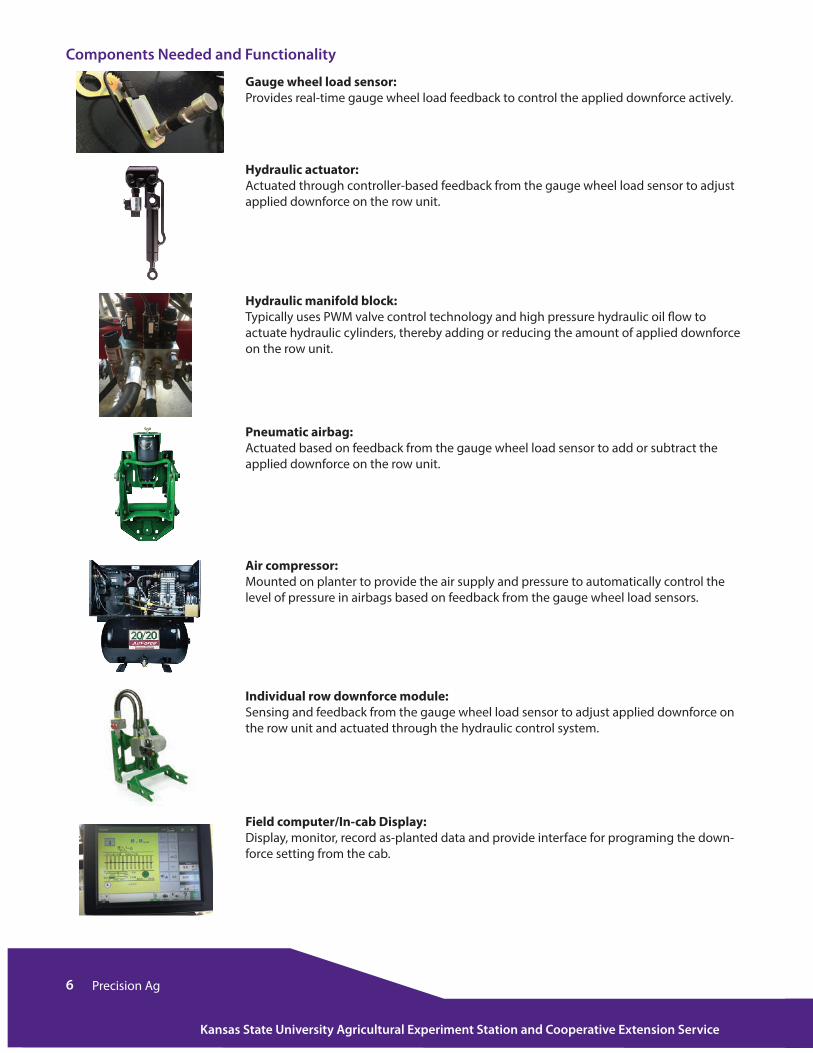
Components Needed and Functionality
Gauge wheel load sensor: Provides real-time gauge wheel load feedback to control the applied downforce actively.
Hydraulic actuator: Actuated through controller-based feedback from the gauge wheel load sensor to adjust applied downforce on the row unit.
Hydraulic manifold block: Typically uses PWM valve control technology and high pressure hydraulic oil flow to actuate hydraulic cylinders, thereby adding or reducing the amount of applied downforce on the row unit.
Pneumatic airbag: Actuated based on feedback from the gauge wheel load sensor to add or subtract the applied downforce on the row unit.
Air compressor: Mounted on planter to provide the air supply and pressure to automatically control the level of pressure in airbags based on feedback from the gauge wheel load sensors.
Individual row downforce module: Sensing and feedback from the gauge wheel load sensor to adjust applied downforce on the row unit and actuated through the hydraulic control system.
Field computer/In-cab Display: Display, monitor, record as-planted data and provide interface for programing the down-force setting from the cab.

7Precision Ag
Kansas State University Agricultural Experiment Station and Cooperative Extension Service
Downforce System ComponentsThe newest hydraulic downforce systems are avail-
able in a number of variants. End users can select a pneumatic system along with load cell(s). A pneumatic system will require an air compressor, which can be powered though an electrical or a hydraulic system, with pulse width modulated air control to regulate high pressure air flow into and out of the pneumatic cylinder; and requires airbags or pneumatic cylinders. A hydraulic system will need a hydraulic block with pulse width modulated flow control to regulate high pressure hydraulic oil flow into and out of hydraulic cylinder; and hydraulic cylinders. Some of the example components are shown in the table on the next page.
SummaryPlanter downforce should be carefully selected
based on soil type, moisture, terrain, and crop residue. It is recommended to consult with equipment manu-facturers for proper implementation of this technology. It is also recommended to do ground in-field checks to make sure the selected planter settings are providing the target depth. For more information on products available from different manufacturers please visit the manufacturers’ websites provided below.
More detailed information on commercially available productswww.agleader.com/products/seedcommand/hydraulic-down-force/
www.deere.com/en_US/parts/parts_by_industry/ag/seeding/depth-control/depth-control.page
www.horsch.com/us/produkte/saemaschinen/einzelkornsaemaschinen/maestro/maestro-sw/
www.precisionplanting.com/#products/airforce/
www.precisionplanting.com/#products/deltaforce/
ReferencesGrisso, R., M. Alley, D. Holshouser, and W. Thom-
ason. 2009. Precision farming tools: Soil electrical conductivity. Virginia Cooperative Extension.
Gratton, J., Chen, Y., and Tessier, S. (2003). Design of a Spring Loaded Downforce System for a No-till Seed Opener. Canadian Biosystems Engineering vol 45: 229-235. http://www.csbe-scgab.ca/publications/cbe-journal/browse/3573-design-of-a-spring-loaded-downforce-system-for-a-no-till-seed-opener
Hanna, H. M., Steward, B. L., & Aldinger, L. (2010). Soil Loading Effects of Planter Depth-Gauge Wheels on Early Corn Growth. Applied Engineering in Agriculture, 26 (4):551-556
Kitchen, N. R., S. T. Drummond, E. D. Lund, K. A. Sudduth and G. W. Buchleiter (2003). Soil electrical conductivity and topography related to yield for three contrasting soil-crop systems. Agron J 95(3): 483-495.
Sharda, A., S. Badua, D. Flippo, T. W. Griffin, and I. Ciampitti. 2016. Real-time gauge wheel load variability on planter with downforce control during field operation. In proceeding of the 13th Interna-tional Conference on Precision Agriculture, St. Louis, Missouri, U.S., July 31st to 2nd, 2016.

Authors:
Ajay Sharda, Precision Ag and Machine Systems Engineer, Biological and Agricultural Engineering, Kansas State University
John Fulton, Associate Professor, Food Biological and Agricultural Engineering, Ohio State UniversitySylvester Badua, Graduate Student, Biological and Agricultural Engineering, Kansas State University
Terry Griffin, Cropping Systems Economist, Agricultural Economics, Kansas State UniversityIgnacio Ciampitti, Cropping Systems Specialist, Agronomy, Kansas State University
Lucas Haag, Northwest Area Agronomist, Agronomy, Kansas State University
Publications from Kansas State University are available at: www.ksre.ksu.edu
Publications are reviewed or revised annually by appropriate faculty to reflect current research and practice. Date shown is that of publication or last revision. Contents of this publication may be freely reproduced for educational purposes. All other rights reserved. In each case, credit Ajay Sharda, Planter Downforce Technology for Uniform Seeding Depth, Kansas State University, March 2017.
Kansas State University Agricultural Experiment Station and Cooperative Extension Service
K-State Research and Extension is an equal opportunity provider and employer. Issued in furtherance of Cooperative Extension Work, Acts of May 8 and June 30, 1914, as amended. Kansas State University, County Extension Councils, Extension Districts, and United States Department of Agriculture Cooperating, John D. Floros, Director.
MF3331 March 2017