Method to Assess Magnetic Fields From Welding Against the ...
10
Method to Assess Magnetic Fields From Welding Against the EU- Directive on Electromagnetic Fields Yngve Hamnerius 1 and Tomas Nilsson 2 Dept. of Signals & Systems Chalmers University of Technology SE412 96 Goteborg Sweden 1). [email protected] 2). [email protected] Abstract The EU Directive 2013/35/EU, which will be enforced in all member states July 1 st 2016, requires that companies carry out a risk assessment for workers exposure to Electromagnetic fields (EMF). EMF:s are created by electric voltages and currents. Large current are used in welding, which gives rise to high magnetic fields, this means that the worker exposure has to be assessed against the limits. The exposure limit values are expressed as the induced electric field strength in the human body. The induced electric field cannot be measured, only calculated in com- puter simulations. Therefore the directive also gives action levels expressed in the magnetic field strength, which can be measured. The magnetic fields in welding are often not sinusoidal and for that reason, the wave- form of the welding current has to be assessed; this can be done using a technique called weighting filters. If the action levels are exceeded, an assessment against the exposure limit values has to be done. An assessment of welding exposure to EMF can be quite complex and costly. To fa- cilitate this assessment, software has been developed in the EU EMFWELD project. 1 INTRODUCTION The EU Directive 2013/35/EU [1] requires that companies carry out a risk assessment for workers exposure to Electromagnetic fields. In the EU project EMFWELD [2] a software toolkit has been developed to assist manufacturing companies, employing welding processes, to carry out that risk assessment. In the project TWI has performed measurements of the magnetic fields in the vicinity of a range of welding equipment. Detailed waveforms have been recorded. At Chalmers University of Technology we have simulated the magnetic fields varia- tion in space from various welding sources. We have assessed the recorded wave- forms from the magnetic field measurements against the requirements of the Directive and simulated the induced electric fields in the welder’s bodies. The magnetic field to which workers are exposed has been limited in terms of expo- sure limit values in the directive. The exposure limit values are expressed as the in- duced electric field strength in the human body. The induced electric field cannot be measured, only calculated in computer simulations. Therefore the directive also gives low, high and limb action levels, which can be measured. The action levels are ex-
Transcript of Method to Assess Magnetic Fields From Welding Against the ...
Method to Assess Magnetic Fields From Welding Against the EU-Directive on Electromagnetic Fields
Yngve Hamnerius1 and Tomas Nilsson2
Dept. of Signals & Systems Chalmers University of Technology
SE412 96 Goteborg Sweden
1). [email protected] 2). [email protected]
Abstract The EU Directive 2013/35/EU, which will be enforced in all member states July 1st 2016, requires that companies carry out a risk assessment for workers exposure to Electromagnetic fields (EMF). EMF:s are created by electric voltages and currents. Large current are used in welding, which gives rise to high magnetic fields, this means that the worker exposure has to be assessed against the limits.
The exposure limit values are expressed as the induced electric field strength in the human body. The induced electric field cannot be measured, only calculated in com-puter simulations. Therefore the directive also gives action levels expressed in the magnetic field strength, which can be measured.
The magnetic fields in welding are often not sinusoidal and for that reason, the wave-form of the welding current has to be assessed; this can be done using a technique called weighting filters. If the action levels are exceeded, an assessment against the exposure limit values has to be done.
An assessment of welding exposure to EMF can be quite complex and costly. To fa-cilitate this assessment, software has been developed in the EU EMFWELD project.
1 INTRODUCTION The EU Directive 2013/35/EU [1] requires that companies carry out a risk assessment for workers exposure to Electromagnetic fields. In the EU project EMFWELD [2] a software toolkit has been developed to assist manufacturing companies, employing welding processes, to carry out that risk assessment. In the project TWI has performed measurements of the magnetic fields in the vicinity of a range of welding equipment. Detailed waveforms have been recorded.
At Chalmers University of Technology we have simulated the magnetic fields varia-tion in space from various welding sources. We have assessed the recorded wave-forms from the magnetic field measurements against the requirements of the Directive and simulated the induced electric fields in the welder’s bodies.
The magnetic field to which workers are exposed has been limited in terms of expo-sure limit values in the directive. The exposure limit values are expressed as the in-duced electric field strength in the human body. The induced electric field cannot be measured, only calculated in computer simulations. Therefore the directive also gives low, high and limb action levels, which can be measured. The action levels are ex-
pressed in the magnetic field strength of the source and they are chosen such that complying with the action levels results in compliance with the exposure limit values.
2 EVALUATION METHOD
Assessing a sinusoidal field against the action levels is quite straight forward, as ta-bles are given for the action levels at different frequencies in the directive. Welding currents are seldom sinusoidal which means that a more advanced analysis is needed. In the case of non-sinusoidal fields it is written in the directive that “exposure evalua-tion carried out in accordance with Article 4 shall be based on the weighted peak method (filtering in time domain)”[1]. We have used weighting filters when assessing the exposure from welding. This is described in section 3.
The exposure limit values are given as the induced electric field strength in the human body. These fields can’t be measured but have to be computer simulated, which is de-scribed in section 4.
3 ASSESSING COMPLEX SIGNALS WITH WEIGHTING FILTERS
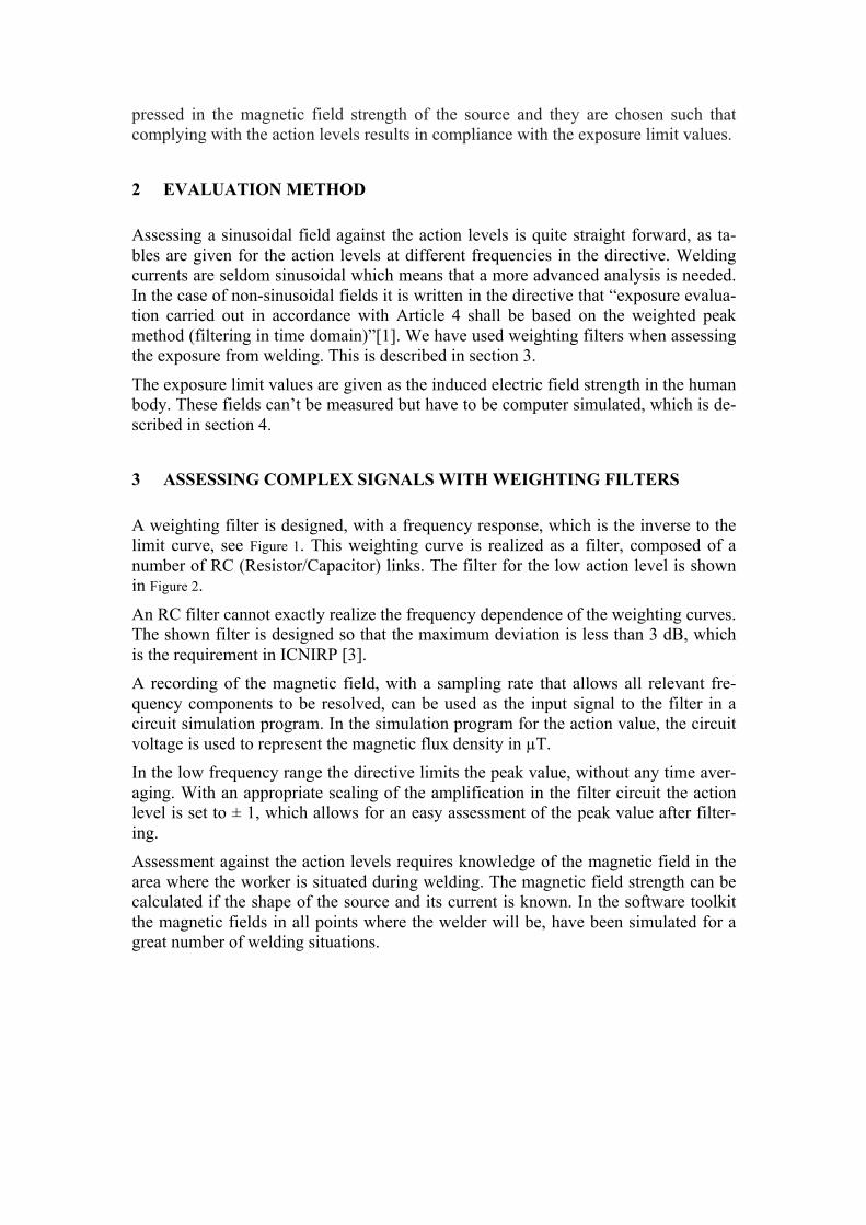
A weighting filter is designed, with a frequency response, which is the inverse to the limit curve, see Figure 1. This weighting curve is realized as a filter, composed of a number of RC (Resistor/Capacitor) links. The filter for the low action level is shown in Figure 2.
An RC filter cannot exactly realize the frequency dependence of the weighting curves. The shown filter is designed so that the maximum deviation is less than 3 dB, which is the requirement in ICNIRP [3]. A recording of the magnetic field, with a sampling rate that allows all relevant fre-quency components to be resolved, can be used as the input signal to the filter in a circuit simulation program. In the simulation program for the action value, the circuit voltage is used to represent the magnetic flux density in µT. In the low frequency range the directive limits the peak value, without any time aver-aging. With an appropriate scaling of the amplification in the filter circuit the action level is set to ± 1, which allows for an easy assessment of the peak value after filter-ing. Assessment against the action levels requires knowledge of the magnetic field in the area where the worker is situated during welding. The magnetic field strength can be calculated if the shape of the source and its current is known. In the software toolkit the magnetic fields in all points where the welder will be, have been simulated for a great number of welding situations.
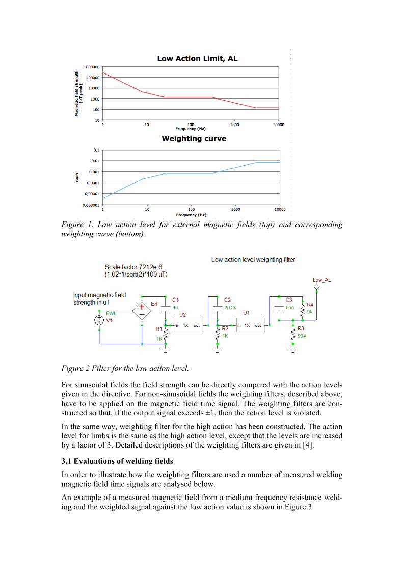
Figure 1. Low action level for external magnetic fields (top) and corresponding weighting curve (bottom).
Figure 2 Filter for the low action level.
For sinusoidal fields the field strength can be directly compared with the action levels given in the directive. For non-sinusoidal fields the weighting filters, described above, have to be applied on the magnetic field time signal. The weighting filters are con-structed so that, if the output signal exceeds ±1, then the action level is violated.
In the same way, weighting filter for the high action has been constructed. The action level for limbs is the same as the high action level, except that the levels are increased by a factor of 3. Detailed descriptions of the weighting filters are given in [4].
3.1 Evaluations of welding fields In order to illustrate how the weighting filters are used a number of measured welding magnetic field time signals are analysed below. An example of a measured magnetic field from a medium frequency resistance weld-ing and the weighted signal against the low action value is shown in Figure 3.
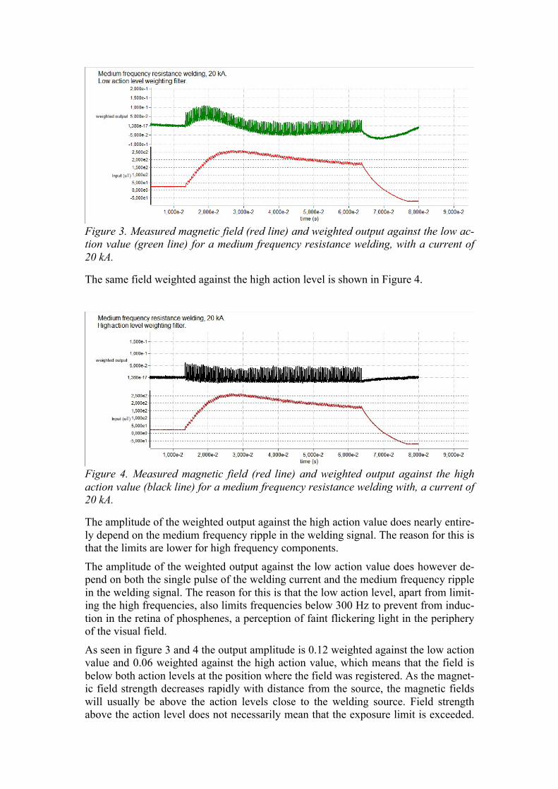
Figure 3. Measured magnetic field (red line) and weighted output against the low ac-tion value (green line) for a medium frequency resistance welding, with a current of 20 kA.
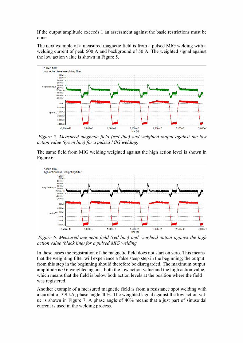
The same field weighted against the high action level is shown in Figure 4.
Figure 4. Measured magnetic field (red line) and weighted output against the high action value (black line) for a medium frequency resistance welding with, a current of 20 kA.
The amplitude of the weighted output against the high action value does nearly entire-ly depend on the medium frequency ripple in the welding signal. The reason for this is that the limits are lower for high frequency components.
The amplitude of the weighted output against the low action value does however de-pend on both the single pulse of the welding current and the medium frequency ripple in the welding signal. The reason for this is that the low action level, apart from limit-ing the high frequencies, also limits frequencies below 300 Hz to prevent from induc-tion in the retina of phosphenes, a perception of faint flickering light in the periphery of the visual field.
As seen in figure 3 and 4 the output amplitude is 0.12 weighted against the low action value and 0.06 weighted against the high action value, which means that the field is below both action levels at the position where the field was registered. As the magnet-ic field strength decreases rapidly with distance from the source, the magnetic fields will usually be above the action levels close to the welding source. Field strength above the action level does not necessarily mean that the exposure limit is exceeded.
If the output amplitude exceeds 1 an assessment against the basic restrictions must be done.
The next example of a measured magnetic field is from a pulsed MIG welding with a welding current of peak 500 A and background of 50 A. The weighted signal against the low action value is shown in Figure 5.
Figure 5. Measured magnetic field (red line) and weighted output against the low action value (green line) for a pulsed MIG welding.
The same field from MIG welding weighted against the high action level is shown in Figure 6.
Figure 6. Measured magnetic field (red line) and weighted output against the high action value (black line) for a pulsed MIG welding.
In these cases the registration of the magnetic field does not start on zero. This means that the weighting filter will experience a false steep step in the beginning; the output from this step in the beginning should therefore be disregarded. The maximum output amplitude is 0.6 weighted against both the low action value and the high action value, which means that the field is below both action levels at the position where the field was registered.
Another example of a measured magnetic field is from a resistance spot welding with a current of 3.9 kA, phase angle 40%. The weighted signal against the low action val-ue is shown in Figure 7. A phase angle of 40% means that a just part of sinusoidal current is used in the welding process.
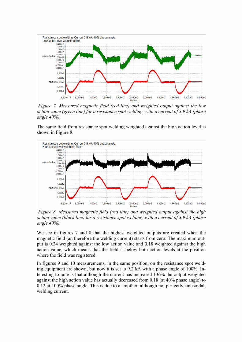
Figure 7. Measured magnetic field (red line) and weighted output against the low action value (green line) for a resistance spot welding, with a current of 3.9 kA (phase angle 40%).
The same field from resistance spot welding weighted against the high action level is shown in Figure 8.
Figure 8. Measured magnetic field (red line) and weighted output against the high action value (black line) for a resistance spot welding, with a current of 3.9 kA (phase angle 40%).
We see in figures 7 and 8 that the highest weighted outputs are created when the magnetic field (an therefore the welding current) starts from zero. The maximum out-put is 0.24 weighted against the low action value and 0.18 weighted against the high action value, which means that the field is below both action levels at the position where the field was registered.
In figures 9 and 10 measurements, in the same position, on the resistance spot weld-ing equipment are shown, but now it is set to 9.2 kA with a phase angle of 100%. In-teresting to note is that although the current has increased 136% the output weighted against the high action value has actually decreased from 0.18 (at 40% phase angle) to 0.12 at 100% phase angle. This is due to a smother, although not perfectly sinusoidal, welding current.
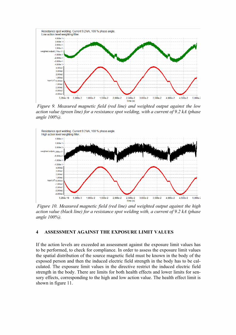
Figure 9. Measured magnetic field (red line) and weighted output against the low action value (green line) for a resistance spot welding, with a current of 9.2 kA (phase angle 100%).
Figure 10. Measured magnetic field (red line) and weighted output against the high action value (black line) for a resistance spot welding with, a current of 9.2 kA (phase angle 100%).
4 ASSESSMENT AGAINST THE EXPOSURE LIMIT VALUES
If the action levels are exceeded an assessment against the exposure limit values has to be performed, to check for compliance. In order to assess the exposure limit values the spatial distribution of the source magnetic field must be known in the body of the exposed person and then the induced electric field strength in the body has to be cal-culated. The exposure limit values in the directive restrict the induced electric field strength in the body. There are limits for both health effects and lower limits for sen-sory effects, corresponding to the high and low action value. The health effect limit is shown in figure 11.
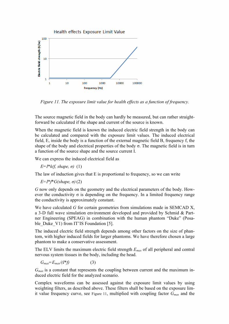
Figure 11. The exposure limit value for health effects as a function of frequency. The source magnetic field in the body can hardly be measured, but can rather straight-forward be calculated if the shape and current of the source is known. When the magnetic field is known the induced electric field strength in the body can be calculated and compared with the exposure limit values. The induced electrical field, E, inside the body is a function of the external magnetic field B, frequency f, the shape of the body and electrical properties of the body σ. The magnetic field is in turn a function of the source shape and the source current I.
We can express the induced electrical field as E=I*k(f, shape, σ) (1)
The law of induction gives that E is proportional to frequency, so we can write E=I*f*G(shape, σ) (2)
G now only depends on the geometry and the electrical parameters of the body. How-ever the conductivity σ is depending on the frequency. In a limited frequency range the conductivity is approximately constant. We have calculated G for certain geometries from simulations made in SEMCAD X, a 3-D full wave simulation environment developed and provided by Schmid & Part-ner Engineering (SPEAG) in combination with the human phantom “Duke” (Posa-ble_Duke_V1) from IT’IS Foundation [5]. The induced electric field strength depends among other factors on the size of phan-tom, with higher induced fields for larger phantoms. We have therefore chosen a large phantom to make a conservative assessment.
The ELV limits the maximum electric field strength Emax of all peripheral and central nervous system tissues in the body, including the head.
Gmax=Emax/(I*f) (3) Gmax is a constant that represents the coupling between current and the maximum in-duced electric field for the analyzed scenario. Complex waveforms can be assessed against the exposure limit values by using weighting filters, as described above. These filters shall be based on the exposure lim-it value frequency curve, see Figure 11, multiplied with coupling factor Gmax and the
frequency, f, to take account for the frequency dependence of the induced electric field strength.
Filters for exposure limit value for health effects can analyze the time registration of the source current signal.
The filters are correct up to 10 MHz, however above 100 kHz the thermal limits ac-cording to the directive have to be checked as well.
With this method, complex signals can be assessed, in the time domain, against the limits, with no need to make the assessment for each frequency component and with-out the risk of overestimation. This will significantly reduce the time required for simulations.
5 DISCUSSION
The described method was developed to solve the problems arising when assessing the EU Directive limits for magnetic fields in welding in the frequency range 1 Hz to 100 kHz. One of the main advantages is that complex waveforms can be analyzed in a straightforward way. By using weighting filters and coupling factors the time and ge-ometrical dependences can be treated separately, which considerably simplifies the assessment and makes it cost effective. As shown in the examples welding magnetic fields can have very different time de-pendence. The amount of higher frequency components is important when assessing compliance with the directive. This can be assessed using weighting filters. Usually higher welding currents give rise to magnetic fields that are less likely to pass the di-rective. The example with the resistance spot welder showed that not only the current but also the phase angle is of great importance. The examples might give the impression that the MIG welding was closest to the limit as it gave the highest weighted output. This is however not true. The MIG was meas-ured close (20 cm) to the welding cable while the other processes where measured at a greater distance (for measurement technical reasons). MIG uses quite moderate cur-rents, while resistance spot welding uses much higher currents and is therefore more likely to exceed the limits. It is possible to measure if there is compliance with the action levels as there exists measurement instruments with built in weighting filters for the action levels. If the action levels are exceeded an assessment against the exposure limit values will show if there is compliance with the directive. In such an assessment there is a need to calculate the induced electric field strength inside the workers body. Unfortunately this is extremely demanding, rarely any employer has the ability to do such calcula-tions. In EMFWELD we have developed a software where both the action values and the exposure limit values are assessed for most welding processes. The user has to give information of the welding process and the position of the welder in relation to the welding equipment. No magnetic field measurements are needed. Building on a data-base of measurements for different welding processes the exposure can be estimated with reasonable accuracy. Conservative assumptions are used for the time dependence of the magnetic fields for the different processes. By using the EMFWELD tool kit most welding exposures can be assessed time and cost effective.
ACKNOWLEDGEMENT This work was performed in the EMFWELD project, which has received funding from the European Community's Seventh Framework Programme managed by REA-Research Executive Agency under grant agreement no. FP7-SME-2012-2-315382-EMFWELD. The magnetic field time signals where supplied by Geoff Melton and Robert Shaw-Edwards at TWI, Cambridge, UK.
REFERENCES
[1] Directive 2013/35/EU of the European parliament and of the council of 26 June 2013 on the minimum health and safety requirements regarding the exposure of workers to the risks arising from physical agents (electromagnetic fields) (20th individual Directive within the meaning of Article 16(1) of Directive 89/391/EEC) and repealing Directive 2004/40/EC.
[2] EMFWELD http://www.emfweld.com/
[3] ICNIRP Guidelines for Limiting Exposure to Time-Varying Electric and Magnetic Fields (1 Hz – 100 kHz). Health Physics 99(6):818-836; 2010.
[4] Hamnerius Y and Nilsson T Assessing Complex Low Frequency Magnetic Fields Against the EU Directive for Worker Protection. International Symposium on Electromagnetic Compatibility - EMC EUROPE (September 2014) available in IEEE Xplore.
[5] Christ A, Kainz W, Hahn E G, Honegger K, Zefferer M, Neufeld E, Rascher W, Janka R, Bautz W, Chen J, Kiefer B, Schmitt P, Hollenbach H-P, Shen J, Oberle M, Szczerba D, Kam A, Guag J W and Kuster N The Virtual Family – Development of Surface-based Anatomical Models of Two Adults and Two Children for Dosimetric Simulations. Physics in Medicine and Biology, Volume 55, Issue 2, pp. N23–N38, January 2010