METHOD 10 STRESS RUPTURE Aerospace THE INITIAL …
13
NASM1312-10 29 August 1997 ADOPTION NOTICE NASM1312-10, "Fastener Test Methods Method 10 Stress Rupture" was adopted on 29 August 1997 for use by the Department ofDefense (DoD). Proposed changes by DoD activities must be submitted to the DoD Adopting Activity: Commander, Naval Air Warfare Center Aircraft Division, Code 414100B120-3 Highway 547, Lakehurst, NJ 08733-5100. DoD activities may obtain copies of this standard from the Standardization Document Order Desk, 700 Robbins Avenue, Building 4D, Philadelphia, PA 19111-5094. The private sector and other Government agencies may purchase copies from the Aerospace Industries Association, 1250 Eye Street NW, Washington, DC 20005. NASM1312-10 Should be used instead of MIL-STD-1312-10, which was cancelled on 29 August 1997. Custodians: Preparing activity: Army - AV Navy - AS Navy - AS (Project No. 53GP-0285-10) Air Force - 11 Review Activities: Arrny - AV, AR Navy - AS, SH Air Force - 11 DLA - IS
Transcript of METHOD 10 STRESS RUPTURE Aerospace THE INITIAL …

NASM1312-10 29 August 1997
ADOPTION NOTICE
NASM1312-10, "Fastener Test Methods Method 10 Stress Rupture" was adopted on 29 August 1997 for use by the Department ofDefense (DoD). Proposed changes by DoD activities must be submitted to the DoD Adopting Activity: Commander, Naval Air Warfare Center Aircraft Division, Code 414100B120-3 Highway 547, Lakehurst, NJ 08733-5100. DoD activities may obtain copies of this standard from the Standardization Document Order Desk, 700 Robbins Avenue, Building 4D, Philadelphia, PA 19111-5094. The private sector and other Government agencies may purchase copies from the Aerospace Industries Association, 1250 Eye Street NW, Washington, DC 20005.
NASM1312-10 Should be used instead of MIL-STD-1312-10, which was cancelled on 29 August 1997.
Custodians: Preparing activity: Army - AV Navy - AS Navy - AS (Project No. 53GP-0285-10) Air Force - 11
Review Activities: Arrny - AV, AR Navy - AS, SH Air Force - 11 DLA - IS
NATIONAL AEROSPACE STANDARD fDCOPYRIGHT 1997 AEROSPACE INDUSTRIES ASSOCIATION OF AMERICA, INC
ALL RIGHTS RESERVED
,1 NASM1312-10 9 1 4 ;it
STAIV4RD PRACTICE
FASTENER TEST METHODS
METHOD 10
STRESS RUPTURE
Aerospace Industries Association
THE INITIAL RELEASE OF THIS DOCUMENT SUPERSEDES MIL-STD-1312-10
DESIGNATION FOR THIS TEST METHOD REMAINS MIL-STD-1312-10
LIST OF CURRENT SHEETS NO. 1 2 3 4 5 6 7 8 9
REV. NEW NEW NEW NEW NEW NEW NEW NEW NEW
SHEET 1 OF 12
APPROVAL DATE AUGUST 1997 USE OF OR RELIANCE UPON THIS DOCUMENT OR ANY AEROSPACE STANDARD IS ENTIRELY VOLUNTARY AIA DOES NOT QUALIFY SUPPLIERS OR CERTIFY CONFORMANCE OF ITEMS PRODUCED UNDER AEROSPACE STANDARDS . AIA MAKES NO REPRESENTATION OR CLAIM RESPECTING (I) THE surnuarry OF ITEMS FOR ANY PARTICULAR APPLICATION OR (2) THE EXISTENCE OF OR APPLICABILITY THERETO OF PATENT OR TRADEMARK RIGHTS.

NATIONAL AEROSPACE STANDARD ©COPYRIGHT 1997 AEROSPACE INDUSTRIES ASSOCIATION OF AMERICA. INC
ALL RIGHTS RESERVED
' 11
NASM1312-10
FOREWORD
This standard sets forth a standard test method to determine the stress rupture limits of fasteners under controlled temperature conditions,
SHEET 2 APPROVAL DATE AUGUST 1997 USE OF OR RELIANCE UPON TRIS DOCUMENT OR ANY AEROSPACE STANDARD IS ENTIRELY VOLUNTARY AIA DOES NOT QUALIFY SUPPLIERS OR CERTIFY CONFORMANCE OF ITEMS PRODUCED UNDER AEROSPACE STANDARDS . AIA MAKES NO REPRESENTATION OR CLAIM RESPECTING (I) THE SUITABILITY OF ITEMS FOR ANY PARTICULAR APPLICATION OR (2) THE EXISTENCE OF OR APPLICABILITY THERETO OF PATENT OR TRADEMARK RIGHTS.

NATIONAL AEROSPACE STANDARD ©COPYRIGHT 1997 AEROSPACE INDUSTRIES ASSOCIATION OF AMERICA, INC
ALL RIGHTS RESERVED
Paragraph
91 1,4 1
TABLE OF CONTENTS
NASM1312-10
Sheet
1. SCOPE 5 1.1 Applicability 5
2. REFERENCED DOCUMENTS 5 2.1 Government documents 5 2.2 Other publications 5
3. DEFINITIONS 5
4. GENERAL REQUIREMENTS 5 4.1 Test apparatus 5 4.1.1 Testing machines 5 4.1.2 Alignment 6 4.1.3 Elapsed time-indicator 6 4.1.4 Temperature measurement and control 6 4.1.5 Thermocouples 6 4.1.5.1 Junction 6 4.1.5.2 Wire 6 4.1.5.3 Instrumenting the specimen 6 4.1.6 Temperature recorder 6 4.1.7 Fixturing 7 4.2 Test specimens 7 4.2.1 Bolt/nut combination 7 4.2.2 Reduced gage section specimens 7 4.2.3 Fabrication of specimens from finished parts 7 4.2.4 Surface 7
, 1 5. DETAIL REQUIREMENTS i .p.11 7 5.1 Test procedures s 7
6. NOTES 8 6.1 Test report 4 8 6.2 Extrapolation/interpolation of data 9 6.3 References 9
SHEET 3 APPROVAL DATE AUGUST 1997 USE OF OR RELIANCE UPON THIS DOCUMENT OR ANY AEROSPACE STANDARD IS ENTIRELY VOLUNTARY AJA DOES NOT QUALIFY SUPPLIERS OR CERTIFY CONFORMANCE OF ITEMS PRODUCED UNDER AEROSPACE STANDARDS . AIA MAKES NO REPRESENTATION OR CLAIM RESPECTING (1) THE SUITABILITY OF ITEMS FOR ANY PARTICULAR APPLICATION OR (2) THE EXISTENCE OF OR APPLICABILITY THERETO OF PATENT OR TRADEMARK RIGHTS.

NATIONAL AEROSPACE STANDARD ((COPYRIGHT 1997 AEROSPACE INDUSTRIES ASSOCIATION OF AMERICA, INC
ALL RIGHTS RESERVED
NASM1312-10
FIGURES Figure Sheet
1. Combination smooth and notched test specimen 10 2. Smooth bar test specimen 11 3. L-M parameter curve 12
SHEET 4 APPROVAL DATE AUGUST 1997 USE OF OR RELIANCE UPON THIS DOCUMENT OR ANY AEROSPACE STANDARD IS ENTIRELY VOLUNTARY AIA DOES NOT QUALIFY SUPPLIERS OR CERTIFY CONFORMANCE OF ITEMS PRODUCE» UNDER AEROSPACE STANDARDS . AlA MAKES NO REPRESENTATION OR CLAIM RESPECTTNG (1) THE SUITABILITY OF ITEMS FOR ANY PARTICULAR APPLICATION OR (2) THE EXISTENCE OF OR APPLICABILITY THERETO OF PATENT OR TRADEMARK RIGHTS.

NATIONAL AEROSPACE STANDARD °COPYRIGHT 1997 AEROSPACE INDUSTRIES ASSOCIATION OF AMERICA, INC
ALL RIGHTS RESERVED 1 ,
NASM1312-10
1. SCOPE
1.1 Applicability. This test method covers the equipment and procedures to be used for stress rupture testing of bolts, screws, nuts, and of associated materials.
2. REFERENCED DOCUMENTS
2.1 Government documents. Not applicable.
2.2 Other publications. The following document(s) forms a part of this specification to the extent specified herein. The issues of the documents which are indicated as DOD adopted shall be the issue in the current DoDISS and the supplement thereto, if applicable.
AMERICAN NATIONAL STANDARDS INSTITUTE (ANSI)
ANSI B46.1 Surface Texture (Surface Roughness, Waviness, and Lay)
(Applicable for copies should be addressed to the American National Standards Institute, 1430 Broadway, New York, NY 10018.)
AMERICAN SOCIETY FOR TESTING AND MATERIALS (ASTM)
ASTM E 4 Load Verificatíon of Testing Machines
(Applications for copies should be addressed to the American Society for Testing and Materials, 1916 Race Street, Philadelphia, PA 19103.)
3. DEFINITIONS Not applicable.
4. GENERAL REQUIREMENTS
4.1 Test apparatug:
4.1.1 Testing machines. Stress rupture machines shall be of the type that will not permit shock loading, overloading, or the introductíon of torque to the test member. They shall be capable of maintaining the applied load within specified limas until rupture or the end of the test period. The loading mechanism shall be capable of ensuring the necessary accuracy of within 1 percent of the applied load, including all variables. The accuracy shall be verified annually by a method complying with ASTM E 4, or equivalent, with a force measuring system traceable to the National Bureau of Standards within the previous two years.
SHEET 5 APPROVAL DATE AUGUST 1997 USE OF OR RELIANCE UPON THIS DOCUMENT OR ANY AEROSPACE STANDARD IS ENTIRELY VOLUNTARY AIA DOES NOT QUALIFY SUPPLIERS OR CERTIFY CONFORMANCE OF ITEMS PRODUCED UNDER AEROSPACE STANDARDS , AIA MAKES NO REPRESENTAT1ON OR CLAIM RESPECTING (1) THE SUITABIUTY OF ITEMS FOR ANY PARTICULAR APPUCAIION OR (2) THE EXISTENCE OF OR APPLICABILITY THERETO OF PATENT OR TRADEMARK RIGHTS.

NATIONAL AEROSPACE STANDARD oCOPYR1GHT 1997 AEROSPACE INDUSTRIES ASSOCIATION OF AMERICA, INC
ALL RIGHTS RESERVED
1 o,e NASM1312-10 .
4.1.2 Alignment. iAlignment shall be controlled using spherical washers, pin and clevis joints, or bearings as required to ensure that no greater than 10 percent difference in strain exists on diametrically-opposed surfaces of a machined test sample.
4.1.3 Elapsed-time indicator. The elapsed-time indicator shall have an accuracy of 1 percent and shall indicate the time in increments of 0.1 hours.
4.1.4 Temperature measurement and control. The heating apparatus shall be capable of controlling the gradient temperatures within the allowable temperature maximum deviations. The controller shall be of the high/low current, saturable reactor, or silicon controlled rectifier type. The cycle of the controller shall not exceed 4 °F total indicated cycle. All critical areas of the test specimen must be controlled to a temperature within 5 °F (up to 1200 °F) and to within 3 °F (aboye 1200 °F) indicated, of the test temperature using good pyrometric practices.
4.1.5 Thermocouples.
4.1.5.1 Junction. All thermocouple junctions shall have welded beads, with no electrical short circuits between positive and negative leads. The beads shall be in contact with the test specimen insulated from the fumace environment. Welding of the thermocouple to the specimen shall be allowed.
4.1.5.2 Wire. Instrument grade thermocouple wire shall be used, with calibration traceable to the National Bureau of Standards. Individual thermocouples shall not be calibrated, nor any correction factors used from calibration.
4.1.5.3 Instrumenting the specimen. Three thermocouples shall be used to indicate the temperatures; one each at the top, middle, and bottom of the test section. The temperature control limits shall apply to all thermocouples.
EXCEPT4ON: When parts have less than two inches exposed length, the gradient thermocouples shall be placed on the adapters adjacent to the test lecidém. In such cases, the allowable temperature variation of the end thermocouple readings hall be two times that indicated in paragraph 4.1.4.
4.1.6 Temperature recorder. The temperature recorder shall be of the potentiometric type with an accuracy of 1/2 percent of full scale or better. AH indicating thermocouple readings shall be recorded for the duration of the test. A multi-point strip-chart recorder of the stated accuracy is satisfactory, which provides an indication of controller drift prior to exceeding the allowable limits.
SHEET 6 APPROVAL DATE AUGUST 1997
USE OF OR RELIANCE UPON THIS DOCUMENT OR ANY AEROSPACE STANDARD IS ENTIRELY VOLUNTARY AIA DOES NOT QUALIFY SUPPLIERS OR CERTIFY CONFORMANCE OF ITEMS PRODUCED UNDER AEROSPACE STANDARDS . AIA MAKES NO REPRESENTATION OR CLAIM RESPECTING (1) THE SUITABILITY OF ITEMS FOR ANY PARTICULAR APPLICATION OR (2) THE EXISTENCE OF OR APPLICABILITY THERETO OF PATENT OR TRADEMARK RIGHTS.

NATIONAL AEROSPACE STANDARD ©COPYRIGHT 1997 AEROSPACE INDUSTRIES ASSOCIATION OF AMERICA, INC
ALL RIGHTS RES ERVED
NASM1312-10
4.1.7 Fixture . The' fixture design is optional. In the case of a bolt being tested, a threaded fixture may be used. Two to three threads must be.exposed adjacent to the shank when bolts or boltlnut combinations are being tested.
4.2 Test specimens.
4.2.1 Boltlnut combination. When specific bolt/nut combinations or integral fasteners supplied in one assembly must be evaluated, the stress rupture test must be performed on the entire assembly. Tests resulting in failure of any component of the assembly shall be considered an assembly failure.
4.2.2 Reducedgage section specimens. Unless specifically noted, the ratio of gage diameter to gage length shall bel to 4 (see figure 1 and 2).
4.2.3 Fabrication of specimens from finished parts. For bolts and screws whose test loads would normally exceed 20,000 pounds, a specimen made from the finished part may be tested in lieu of the fastener (see figure 1 for dimensions and configuration). When the test temperature becomes impossible to maintain in both the smooth and notched sections, separate specimens shall be prepared in accordance with figure 2 and individually tested.
4.2.4 Surface. Unless otherwise specified, uncoated or metallic-coated test specimens shall be thoroughly free of dirt, oil, and grease. Specimens shall be cleaned with detergent and rinsed with deionized water to obtain a water-break-free surface, followed by rinsing with isopropyl alcohol and air or blow drying. No halogenated solvents or abrasives of any type are permitted. Specimen cleaning must be done within one hour of test. Specimen shall be processed with a minimum of handling and handled only with clean, lintless cotton gloves alter the cleaning operation.
5. DETALL REQUIREMENTS
5.1 Test procedure,
5.1.1 Assemble the test member into the appropriate test fixtures. Attach thermocouples to the test member in accordance with paragraph 4.1.5.3. Assemble the furnace or heating apparatus over the test member. Care shall be taken that the furnace neither adds nor detracts from the test load.
5.1.2 When the test temperature is attained, and the gradient established, maintain the test temperature for at least thirty minutes to ensure uniform test member heating and temperature equilibrium prior to loading.
SHEET 7 APPROVAL DATE AUGUST 1997 • USE OF OR REL1ANCE UPON THIS DOCUMENT OR ANY AEROSPACE STANDARD IS ENTIRELY VOLUNTARY A1A DOES NOT QUALIFY SUPPLIERS OR CERTIFY CONFORMANCE OF ITEMS PRODUCED UNDER AEROSPACE STANDARDS . A1A MAKES NO REPRESENTATION OR CLAIM RESPECTING (1) THE SUITABILITY OF ITEMS FOR ANY PARTICULAR APPLICATION OR (2) THE EXISTENCE OF OR APPLICABILITY THERETO OF PATENT OR TRADEMARK RIGHTS.

NATIONAL AEROSPACE STANDARD OCOPYRIGHT 1997 AEROSPACE INDUSTRIES ASSOCIATION OF AMERICA, INC
ALL RIGHTS RESERVED
NASM1312-10
5.1.3 Apply the load at the prescribed rate. If load, rate is not defined, apply the load over a time frame not to exceed one minute to ensure that the test member is not shocked or overloaded.
5.1.4 Maintain the test load and temperature until specimen fracture occurs or the required test time has elapsed.
5.1.5 Any temperature change outside of the limits specified, shall be cause for rejection of the test, and shall require retesting.
5.1.6 Unless otherwise specified, the maximum test duration shall be 24 hours. For development work, continue stress rupture testing until failure occurs.
6. NOTES
6.1 Test report. The test report shall contain the following data:
a. Fastener description. 1. Part number. 2. Lot identification. 3. Material. 4. Heat treatment. 5. Grip length. 6. Mating part. 7. Measured diameter.
b. Test machine 1. Model and serial number. 2. Calibration date.
c. Test method (where options are available).
d. Test load.
e. Load rate.
f. Test duration.
g. Type of failure.
h. Temperature reading.
SHEET 8 APPROVAL DATE AUGUST 1997 USE OF OR RELIANCE UPON THIS DOCUMENT OR ANY AEROSPACE STANDARD 1S ENTIRELY VOLUNTARY AIA DOES NOT QUALIFY SUPPLIERS OR CERTIFY CONFORMANCE OF ITEMS PRODUCED UNDER AEROSPACE STANDARDS . AIA MAKES NO REPRESENTATION OR CLAIM RESPECTING (I) THE SUITABILITY OF ITEMS FOR ANY PARTICULAR APPLICATION OR (2) THE EXISTENCE OF OR APPLICABILITY THERETO OF PATENT OR TRADEMARK RIGHTS.
NATIONAL AEROSPACE STANDARD CCOPYRIGHT 1997 AEROSPACE INDUSTRIES ASSOCIATION OF AMERICA, INC
ALL RIGHTS RESERVED
NASM1312-10
i. Cause and length of interruption during test
j. Results of all inspections.
k. Specimen preparation.
1. Installation procedure.
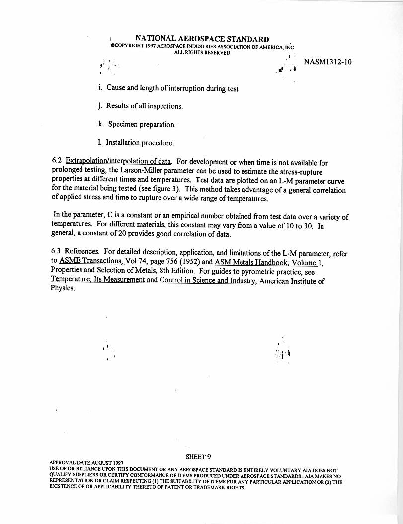
6.2 Extrapolation/interpolation of data. For development or when time is not available for prolonged testing, the Larson-Miller parameter can be used to estimate the stress-rupture properties at different times and temperatures. Test data are plotted on an L-M parameter curve for the material being tested (see figure 3). This method takes advantage of a general correlation of applied stress and time to rupture over a wide range of temperatures.
In the parameter, C is a constant or an empirical number obtained from test data over a variety of temperatures. For different materials, this constant may vary from a value of 10 to 30. In general, a constant of 20 provides good correlation of data.
6.3 References. For detailed description, application, and limitations of the L-M parameter, refer to ASME Transactions, Vol 74, page 756 (1952) and ASM Metals Handbook. Volume 1, Properties and Selection of Metals, 8th Edition. For guides to pyrometric practice, see Temperature, Its Measurement and Control in Science and Industry, American Institute of Physics.
SHEET 9 APPROVAL DATE AUGUST 1997
USE OF OR REIIANCE UPON THIS DOCUMENT OR ANY AEROSPACE STANDARD IS ENTIRELY VOLUNTARY AIA DOES NOT QUALIFY SUPPLIERS OR CERTIFY CONFORMANCE OF ITEMS PRODUCED UNDER AEROSPACE STANDARDS . AIA MAKES NO REPRESENTATION OR CLAIM RESPECTING (1) TIIE SUITAI3ILITY OF ITEMS FOR ANY PARTICULAR APPLICATION OR (2) THE EXISTENCE OF OR APPLICABILITY TIIERETO OF PATENT OR TRADEMARK RIGHTS.

rE-11
a--I
lT
DETAIL A
NATIONAL AEROSPACE STANDARD °COPYRIGHT 1997 AEROSPACE INDUSTRIES ASSOCIATION OF AMERICA, INC
ALL RIGHTS RESERVED I , NASM1312-10
r--B-1 Di
HJT
A
ROOT RADIOS RR
Spec imen No.
D Cerner gage
diameter +_0.0001
(in.)
C + 0.0625
(in.)
G min
(in.)
E min
(in.)
F +0.001
(in.)
1-1 ±0.003
(in.)
R min
+0.0005
(in.)
RR ±0.0005
(in.)
T Min thd size
UNF-3A
1 0.125 0.125 0.5 0.375 0.125 0.177 0.125 0.005 0.2500-28 2 0.150 0.125 0.6 0.375 0.150 0.212 0.125 0.005 0.3125-24 3 0.160 0.125 0.65 0.375 0.160 0.226 0.125 0.005 0.3125-24 4 0.178 0.125 0.75 0.375 0.178 0.250 0.125 0.005 0.3125-24 5 0.252 0.125 1.0 0.375 0.252 0.375 0.125 0.007 0.5000-20 6 0.357 0.125 1.5 0.375 0.357 0.500 0.125 0.010 0.6250-18 7 0.505 0.125 2.0 0.375 0.505 0.750 0.125 0.015 0.8750-14
NOTES: 1. Unless otherwise specified, surface texture 125 microinches in accordance with
ANSI B46.1.' •• ' f i 2. The difference between "F" and "D" shall not exceed 0.0005-inch for spkcimens 1,
2, 3 and 4; and 0.0001 for specimens 5, 6 and 7. 3. Taper gage length "G" to center so that "D" at the ends of the gage length
exceeds "D" at the center of the gage i length by 0.0005 to 0.0015-inch. 4. AH sections shall be concentric about the specimen axis within 0.001-inch. 5. Dimensions "A" and "B" are not specified. 6.' Where fastener length is insufficient to produce a specimen to figure 1, separate
smooth and notched specimens may be individually tested.
FIGURE 1. Combination smooth and notched test specimen.
SHEET 10
H F
APPROVAL DATE AUGUST 1997 USE OF OR RELIANCE UPON THIS DOCUMENT OR ANY AEROSPACE STANDARD IS ENTIRELY VOLUNTARY AIA DOES NOT QUALIFY SUPPLIERS OR CERTIFY CONFORMANCE OF ITEMS PRODUCED UNDER AEROSPACE STANDARDS . AIA MAKES NO REPRESENTATION OR CLAIM RESPECTING (1) THE SUITABILITY OF ITEMS FOR ANY PARTICULAR APPLICATION OR (2) THE EX1STENCE OF OR APPL1CABILITY THERETO OF PATENT OR TRADEMARK RIGHTS.

• G
NASM1312-10 LI I
H
NATIONAL AEROSPACE STANDARD OCOPYRIGHT 1997 AEROSPACE INDUSTRIES ASSOCIATION OF AMERICA, INC
ALL RIGHTS RESERVED
Specimen no.
Diameter D
(in.)
L +0.0625
(in.)
E nominal
(in.)
R
(in.)
B nominal
(in.)
Thread UNF-3A
H nominal
(in.) 1 0.125 1.10 0.04 0.250 0.25 0.2500-28 0.177 2 0.160 1.40 0.06 0.250 0.30 0.3125-24 0.226 3 0.252 2.20 0.08 0.375 0.50 0.5000-20 0.375 4 0.357 3.30 0.12 0.375 0.68 0.6250-18 0.500 5 0.505 4.40 0.16 0.375 0.88 0.8750-14 0.750
NOTES: 1. Unless otherwise specified, the maximum surface texture shall be 125 microinches in accordance with ANSI B46.1. 2. Taper gage length "G" to center so that "D" at the ends of the gage length exceeds "D" at the center of the gaga length by 0.0005-inch to 0.0015-inch. 3. All sections shqllbe concentric about the specimen axis within 0.0001-t .
FIGURE 2. Smooth bar test specimen.
SHEET 11 APPROVAL DATE AUGUST 1997 USE OF OR RELIANCE UPON THIS DOCUMENT OR ANY AEROSPACE STANDARD IS ENTIRELY VOLUNTARY AIA DOES NOT QUALIFY SUPPLIERS OR CERTIFY CONFORMANCE OF ITEMS PRODUCED UNDER AEROSPACE STANDARDS . AIA MAKES NO REPRESENTATION OR CLAIM RESPECTING (1) THE SUITABILITY OF ITEMS FOR ANY PARTICULAR APPLICATION OR (2) THE EXISTENCE OF OR APPLICABILITY THERETO OF PATENT OR TRADEMARK RIGHTS.

NASM1312-10
STRESS LEVEL C •
NATIONAL AEROSPACE STANDARD CCOPYRIGHT 1997 AEROSPACE INDUSTRIES ASSOCIATION OF AMERICA, INC
ALL RIGHTS RESERVED
STRESS LEVEL
STRESS LEVEL A
LOG TIME
LOG STRESS
PARAMETER PzT (C + LOG t) I •
HOURS
FIGURE 3. L-M parameter curve.
SHEET 12 APPROVAL DATE AUGUST 1997 USE OF OR RELIANCE UPON THIS DOCUMENT OR ANY AEROSPACE STANDARD IS ENTIRELY VOLUNTARY AIA DOES NOT QUALIFY SUPPLIERS OR CERTIFY CONFORMANCE OF ITEMS PRODUCED UNDER AEROSPACE STANDARDS . AIA MAKES NO REPRESENTATION OR CLAIM RESPECTING (I) THE SUITABILITY OF ITEMS FOR ANY PARTICULAR APPLICATION OR (2) THE EXISTENCE OF OR APPLICABILITY THERETO OF PATENT OR TRADEMARK RIGHTS.