Metering pumps, components and metering systems 2019 · Chemical transfer and peristaltic pumps,...
394
Product catalogue 2019 Metering Technology 2019
Transcript of Metering pumps, components and metering systems 2019 · Chemical transfer and peristaltic pumps,...

ProduMeterin
19
ct catalogue 2019 g Technology
20

Issued by:
ProMinent GmbIm Schuhmach69123 HeidelbeGermanyPhone +49 [email protected]
Technical chan
All previous caYou can view o
Heidelberg, Ja
Hergewann 5-11rg
1 842–0t.comt.com
ges reserved.
talogues and price lists are superseded with the release of this product catalogue.ur general terms and conditions on our homepage.
nuary 2019

Product Catalogue Volume 1
1.0.1www.prominent.comProduct Catalogue Volume 1
Metering technology for professionalsThe heart of metering technology is quite clearly the pump.With its optimum capacity range and functionality adapted to the feed chemical, it is responsible for smooth-running metering processes.
Chapter 1Low-pressure metering pumps covers metering pumps, ranging from micro-metering pumps to pumps delivering up to 75 l/h at a maximum back pressure of 60 bar.Motor-driven metering pumps for universal use in the low-pressure range up to a capacity of 1,000 l/h at a maximum back pressure of 16 bar, to ensure that your processes operate safely even meeting maximum requirements.Chemical transfer and peristaltic pumps, durable and easy to operate, for pump capacities of up to 100 m3/h, as well as the matching components, like sturdy storage tanks and collecting pans.Metering systems, fully engineered to, standard or made-to-measure – the precisely configured components ensure a safe and immediately ready-to-use complete solution.
Chapter 2Process metering pumps specifically tailored to high-end applications for hazardous production applications in the petrochemical, oil and gas industry. Products that are certified, covering high pressure and extreme temperature applications, that will just carry on metering, even with toxic, corrosive and inflammable liquids.
Ready for you. Anytime, anywhere.ProMinent is close to hand no matter where you are: 55 dedicated sales, production and service companies guarantee service and availability in close proximity to our customers. For many years this has meant a local presence for our customers in over 100 countries.
Our sales team will be happy to be of assistance should you have any questions about metering technology or water treatment. You will find the contact details of your local contact at www.prominent.com/en/locations.
Pump GuideYou can also find information online. The ProMinent pump selection guide is available on our website. Just enter the required pump capacity and back pressure, and the Pump Guide will show you a list of suitable metering pumps. This is the quick and easy way to track down precisely the right pump for your needs.www.pump-guide.com
Metering Pumps, Components and Metering Systems

Step by Step to the Right Product
1.0.1www.prominent.comStep by Step to the Right Product
The following data sheet will help in solving your metering problem. Please enter your requirements and conditions and return it to [email protected]. Our Service Centre will use your data to reach the optimum result - the optimum metering pump and matching accessories for your application.
SG_0037_DEWe'd be pleased to go through these points with you by phone. We're there to help!
Metering tasks come in all shapes and sizes! Provide us with your specification and we will deliver the optimum solution!
Required Data for Designing Metering Pumps and Accessories
Min./max. required feed rate l/hAvailable power supply V, HzMin./max. operating temperature °CProperties of process chemicalName, concentration %Solids content %Dynamic viscosity mPa (= cP)Vapour pressure at operating temperature barRemarks, e.g. abrasive,gaseous, flammable,corrosive towards
Suction conditions:
Min./max. suction lift mMin./max. positive suction head mPressure in chemical tank barSuction line length mSuction line diameter mm
Discharge conditions:
Min./max. back pressure barMin./max. discharge head mMin./max. negative discharge head mDischarge line length mDischarge line diameter mmNumber of valves and fittings insuction and discharge line
Data required for proportionaldosing:
Water flow Q min./max. m3/hRequired final concentration g/m3, ppm
Example :A required dose in mg/l = g/m3 = ppm(Water flow Q max. 50 m3/h)Pulse spacing (flow volume per pulse) of water meter 5 l.Process fluid = sodium hypochlorite solution Na OCl with 12 % chlorine (by weight) = 120 g/kg = 150 g/l = 150 mg/mlSelected dosing pump GMXa 1604NPT2 NPB2 with 0.3 ml/per stroke volume, at max. 10800 strokes/h.Variables: pump type, pulse spacing and concentration. The stroke rate (max. throughput l/h: pulse spacing l/pulse = 50,000 l/h : 5 l/pulse= 10000 pulses/h) must not exceed the max. stroke frequency (10800 strokes/h) of the dosing pump.
Feed quantity = water throughput Q max. (l/h) x stroke volume (l)
=
pulse spacing (l) h x 5 l
Final dose = concentration (mg/ml) x stroke volume (l)
= 150 mg x 0.3 ml
= 9 mg/lpulse spacing (l) ml x 5 l
= 9 g/m3
= 9 ppm chlorine Cl2
50,000 l x 0.0003 l = 3 l/h

Free Choice with the Identity Code
1.0.1www.prominent.comFree Choice with the Identity Code
You've opted for a pump product range. It's now up to you to configure the pump exactly to meet your individual needs.First determine the pump type (1). This is based on the pump capacity you require and the back pressure present. Enter the result at the very bottom, in the grey row of the identity code.The medium to be metered is crucial when it comes to the material of the dosing head (2) and the seals (3). Once again enter the selected code in the bottom row.You can now select the features and properties of your product to suit your process and application parameters.Work through column by column, generating the identity code for your own individual metering pump requirement.
We will be happy to advise you on your metering application.Give us a call should you still have any questions!
Use the identity code to determine the properties and features of your metering pump. Simply select, enter the code in the bottom row and you've configured your product!
BT5b 0713 NP
BT4b Type Capacity
bar l/h
1000 10 0.74
1601 16 1.10
1602 16 2.20
1604 16 3.60
0708 7 7.10
0413 4 12.30
0220 2 19.00
BT5b
2504 25 2.90
1008 10 6.80
0713 7 11.00
0420 4 17.10
0232 2 32.00
Liquid end/valve material
PP Polypropylene/PVDF, for version self-degassing Polypropylene/Polypropylene
NP Acrylic glass/PVDF, for version self-degassing Acrylic glass/PVC
PV PVDF/PVDF
TT PTFE/PTFE
SS Stainless steel 1.4404/1.4404
Seal/diaphragm material
T PTFE/PTFE coated
S Diaphragm additionally with FKM coating for siliceous media
Liquid end version
0 Non-bleed version, no valve spring, for TT, SS and type 0232 only
1 Non-bleed version, with valve spring, for TT, SS and type 0232 only
2 With deaerator, no valve spring, PP, PV, NP only, not type 0232
3 With deaerator, with valve spring, PP, PV, NP only, not type 0232
4 version for highly viscous media, only PVT, types 1604, 0708, 1008, 0413, 0713, 0220, 0420
7 self-bleeding without bypass (SER), only for NP and PV, not for types 1000, 1601 and 0232
Hydraulic connections
0 Standard according to technical data
5 Connector for 12/6 hose, delivery side only, only with materials PP, NP and PV
9 Connector for 10/4 hose, delivery side only, only with materials PP, NP and PV
Version
0 Standard
Logo
0 with ProMinent ® logo
Power supply
U 100-230 V ± 10 %, 50/60 Hz
M 12-24 V DC, only for BT4
N 24 V DC, only for BT5
Cable and plug
A 2 m European
B 2 m Swiss
C 2 m Australian
D 2 m USA
1 2 m, open-ended
Relay
0 No relay
1 Fault indicating relay, normally energised, 1 x changeover contact 230 V - 2 A
3 Fault indicating relay, normally de-energised, 1 x changeover contact230 V - 2 A
4 as 1 + pacing relay 2 x normally open contacts 24 V - 100 m
5 as 3 + pacing relay 2 x normally open contacts 24 V - 100 mA
Accessories
0 No accessories
1 With foot and dosing valve, 2 m PVC suction tubing, 5 m PE discharge tubing
Control type
0 No lock
1 With lock: manual operation locked when external cable plugged in
Control Variants
0 Standard
Options on request
0 0 No options
Metering Pumps also Need Accessories
1.0.1www.prominent.comMetering Pumps also Need Accessories
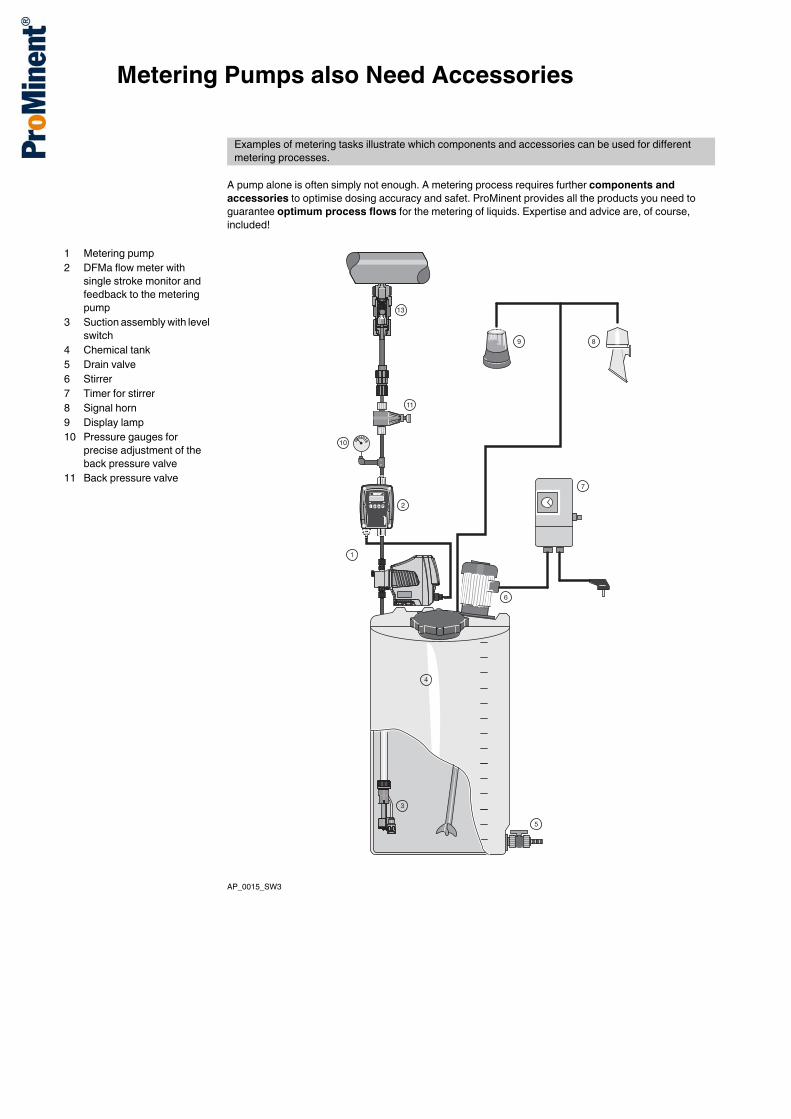
A pump alone is often simply not enough. A metering process requires further components and accessories to optimise dosing accuracy and safet. ProMinent provides all the products you need to guarantee optimum process flows for the metering of liquids. Expertise and advice are, of course, included!
AP_0015_SW3
Examples of metering tasks illustrate which components and accessories can be used for different metering processes.
1 Metering pump2 DFMa flow meter with
single stroke monitor and feedback to the metering pump
3 Suction assembly with level switch
4 Chemical tank5 Drain valve6 Stirrer7 Timer for stirrer8 Signal horn9 Display lamp10 Pressure gauges for
precise adjustment of the back pressure valve
11 Back pressure valve
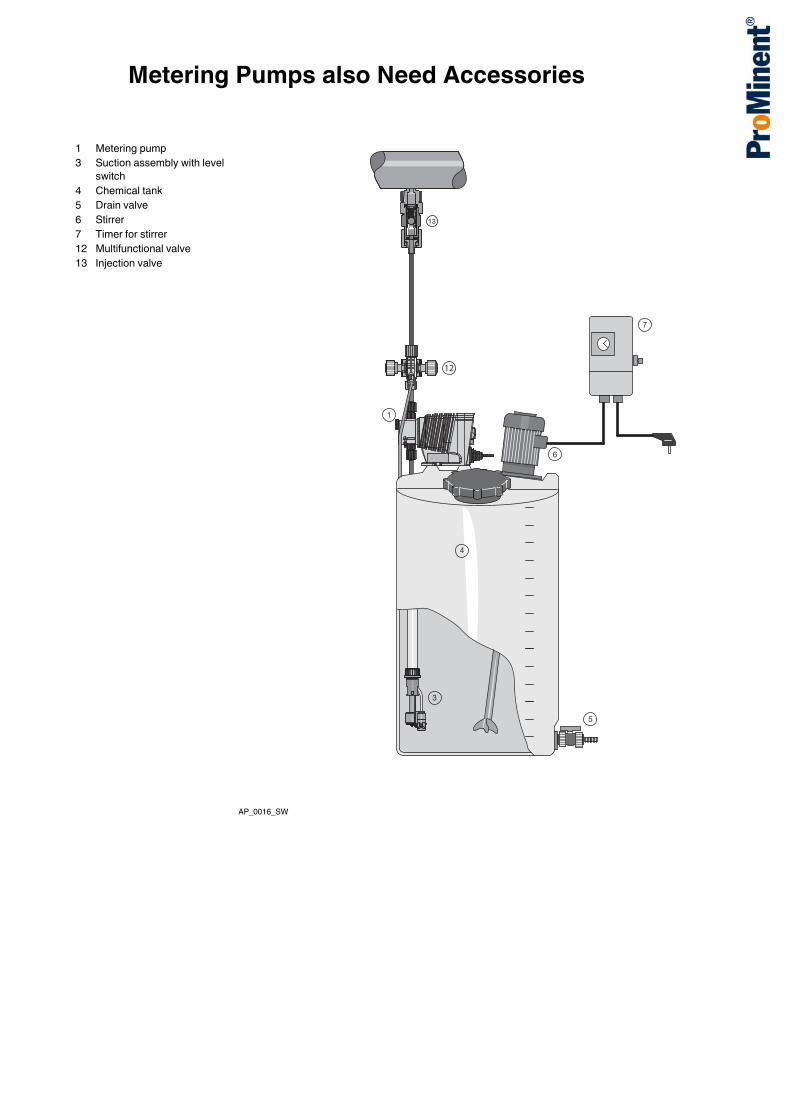
Metering Pumps also Need Accessories
AP_0016_SW
1 Metering pump3 Suction assembly with level
switch4 Chemical tank5 Drain valve6 Stirrer7 Timer for stirrer12 Multifunctional valve13 Injection valve
12


Metering Technology Product Innovations
1.0.1www.prominent.comMetering Technology Product Innovations
IoT module DULCOnnect®
The DULCOnnect® IoT/Industry 4.0 module lets you securely and reliably monitor pumps, sensors, controllers and disinfection systems by smartphone, tablet or computer, independently of their location. Adjustable alarms inform users promptly by e-mail or push notification about important events and the web portal provides access to current and historical unit data at all times. The data can be exported in CSV format, as an Excel document or as a PDF report, for instance to comply with statutory documentation obligations. Flexible management of devices enables them to be sensibly grouped and thus viewed at a glance.All key device-specific values can be monitored and documented alongside error and alarm statuses. With pumps, this includes pressure and the metered volume. With controllers, this includes the values of the connected sensors (for example pH, ORP and turbidity) and, with UV disinfection systems, the radiation intensity and temperature are recorded, among other things.Communication with the connected devices is via Ethernet or via CANopen at field bus level. The DULCOnnect® IoT/Industry 4.0 module securely sends all data with SSL/TLS encryption by GSM or Wi-Fi, enabling real-time monitoring of global systems. User-specific data and measured values are stored in separate databases and measured values are internally anonymised to achieve maximum data security.The DULCOnneX web portal can be accessed via https://dulconnect.prominent.com . Web-based fluid management Simple commissioning Communication via GSM or Wi-FiFor more information see page → 1-125
Solenoid-driven metering pump gamma/ XLCapacity range 8 – 80 l/h, 2 – 25 barThe new solenoid-driven metering pump gamma/ XL is the next level up to our proven gamma/ X and covers a capacity range from 8 – 80 l/h at 2 – 25 bar. The gamma/ XL also has other interfaces, for example CAN bus and Wi-Fi connections. This allows the gamma/ XL to network with all systems, devices and platforms. Like the gamma/ X, the gamma/ XL has an intuitive operating concept. The pump is adjusted using a click wheel and 4 additional operating keys. Pressure detection without wetted parts ensures maximum operational safety. Hydraulic error statuses, like “Gas in the dosing head”, “Overpressure” and “No pressure” can be detected.Pressure fluctuations in the system are detected and compensated for, achieving a high level of dosing precision and reducing chemical consumption to the required level.The last 300 events are retrospectively saved in the integral log book, which permits rapid analysis of the cause and troubleshooting.Deviations from the metering volume or hydraulic fault statuses are immediately detected and corrected by the gamma/ XL. The pump’s operating menu includes ordering information for the wear parts required.
https://dulconnect.prominent.com
1.1.2019

Metering Technology Product Innovations
Designed as a smart product, it can also be connected to our web-based DULCOnneX fluid management platform. The user can use this to monitor his metering process in real time, avoid downtimes and generate reports fully automatically. Simple adjustment of the capacity directly in l/h or in gph Integrated pressure measurement and display for greater safety during commissioning and in the
process Bluetooth and Wi-Fi connection for the simple configuration and call-up of process data (optional) Capacity adjustment range 1:40,000 Direct input of the required final concentration with volume-proportional metering tasks in concentration
mode Virtually wear-free solenoid drive, overload-proof and economical Suitable for continuous micro-metering from approx. 5 ml/h, thanks to the regulated solenoid drive Detection of hydraulic malfunctions, such as gas in the dosing head, and no or too high back pressure,
ensures smooth processes External control via potential-free contacts with pulse step-up and step-down External control via 0/4-20 mA standard signal, scalable Integrated 1-week/1-month timer Guaranteed metering by means of automatic bleeding Connection to process control systems via a BUS interface, such as PROFIBUS®, PROFINET®, CAN
bus or Wi-Fi Automatic mode – volume settings only (l/h, ml/contact etc.) Non-automatic mode – settings via stroke length and stroke rateFor more information see page → 1-16
Motor-driven metering pump Sigma C control typeCapacity range S1Cb: 21 – 117 l/h, 4 – 12 barCapacity range S2Cb: 61 – 353 l/h, 4 – 16 barCapacity range S3Cb: 182 – 1,040 l/h, 4 – 12 barThe Sigma X diaphragm metering pump covers a capacity range of 21 to 1,040 l/h in versions S1Cb, S2Cb and S3Cb. Its patented multi-layer safety diaphragm guarantees maximum process reliability. Efficient protection of the power end from overloading by means of an integral frequency converter with microprocessor control(ler).One highlight is the standardised operating concept with click wheel and 4 additional operating keys on a removable operating unit. A large illuminated LCD and a 3-LED display for operating, warning and error messages, visible from all sides, offers additional operating convenience.The Sigma, like all smart ProMinent metering pumps, can be flexibly connected to various bus systems.It has a large adjustment range thanks to a combination of frequency and stroke length adjustment. The pump works with high precision across the entire frequency range. Accurate and complication-free metering of viscous and gaseous media by adjustment of the movement profile.Operating statuses are simply remotely transmitted via an additional output or relay module. A built-in timer, included as standard, controls time-dependent metering cycles.Relevant spare parts can be shown in the display. The integral log book significantly improves process management, optimisation and troubleshooting. Safe: In the event of an accident, the feed chemical does not escape to the outside nor into the pump's
power end, thanks to the patented multi-layer safety diaphragm with optical (optionally electric) signalling.
Integrated relief valve protects the pump against overloading and reliable operation by means of a bleed option during the metering process.
External control is scalable via potential-free contacts with pulse step-up and step-down, batch mode or via a 0/4-20 mA standard signal.
Flexibly connectible: Connection to process management systems via integral PROFIBUS®, CANopen interface.
Integral log book saves up to 300 events and simplifies troubleshooting and analysis of the cause.For more information see page → 1-39
1.1.2019
Metering Technology Product Innovations
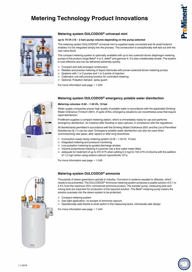
Metering system DULCODOS® universal miniup to 75 l/h (10 – 2 bar) pump volume depending on the pump selectedThe metering system DULCODOS® universal mini is supplied ready connected and its small footprint enables it to be integrated simply into the process. The construction is exceptionally well laid out with the new valve block.The compact metering system is optionally available with up to two solenoid-driven diaphragm metering pumps of the product range Beta® 4 or 5, delta® and gamma/ X. It is also unbelievably simple. The system is cost-effective and can be delivered extremely quickly. Compact and well-arranged construction Reliable and precise metering of liquid chemicals with proven solenoid-driven metering pumps Systems with 1 or 2 pumps and 1 or 2 points of injection Calibration unit with priming function for controlled metering Optional: Pulsation damper, spray guardFor more information see page → 1-224
Metering system DULCODOS® emergency potable water disinfectionMetering volumes: 0.02 – 1.55 l/h, 10 barWater supply companies ensure high quality of potable water in accordance with the applicable Drinking Water Ordinance (TrinkwV 2001). In spite of this, emergency situations can nevertheless arise that require rapid disinfection.ProMinent supplies a compact metering station, which is immediately ready for use and performs emergency disinfection, for instance after flooding or pipe ruptures, in compliance with the regulations.All disinfectants permitted in accordance with the Drinking Water Ordinance 2001 and the List of Permitted Substances (§ 11) can be used. Emergency potable water disinfection can also be used when commissioning new pipes, after repairs or after long downtimes. Connection-ready handy metering system (0.02 – 1.55 l/h, 10 bar) Integrated metering and pressure monitoring Low-pulsation metering by guided discharge strokes Volume-proportional metering if customer has a flow water meter fitted adequate for treatment of up to 372 m3/h when adding 0.5 mg/l to 155 m3/h of chlorine with the addition
of 1.2 mg/l (when using sodium-calcium hypochlorite 12%)For more information see page → 1-245
Metering system DULCODOS® ammoniaThousands of steam generators operate in industry. Corrosion in systems equates to idleness, which needs to be prevented. The DULCODOS® Ammonia metering system produces a usable solution of 0.1 to 2.5% from the maximum 25% commercial ammonia product. The transfer pump, measuring tank and mixing tank are important for production of the required solution. The Beta® metering pump meters the solution precisely into the steam system to be protected. Compact metering system Gas-tight application, no escape of ammonia vapours Operationally safe thanks to level switch in the measuring tanks, intrinsically safe designFor more information see page → 1-244
1.1.2019

Metering Technology Product Innovations
Hydraulic diaphragm metering pump Evolution mikroCapacity range 3 – 23 l/h, 400 – 25 barWith a capacity range of 0.01 – 23 l/h at pressure of up to 400 bar, the hydraulic diaphragm metering pump Evolution mikro EFMa and EHMa is extremely suitable for ultra-precise micro-metering in gas metering and in filling processes of all kinds. It is also used for additive metering in the petrochemical and chemical industry. The Evolution mikro is designed in compliance with API 675, ATEX and FDA.Maximum process reliability: Precise micro-metering at high pressures Hermetically sealed by PTFE or metal multi-layer safety diaphragm Long service life thanks to its sturdy construction with non-wearing, contactless power end High positioning accuracy (in the micron range) and zero backlash (no overload)Excellent flexibility: Seriously extended adjustment range of 1:200 Universally controllable with electronically integrated overload protection Individual process-dependent metering profiles are possible Space-saving, easy-to-assemble solution with flexible arrangement of the power endsFor more information see page → 2-49
Hydraulic diaphragm metering pump Orlita® Evolution API 674Capacity range per pump head: 3 – 511 l/h, 400 – 8 barOrlita® Evolution hydraulic diaphragm metering pumps ER1a, EF2F, EF3F and EF4F form an integrated product range with stroke lengths of 15 to 40 mm. This covers the capacity range from 3 to 7,400 l/h at 400 – 10 bar. A wide range of drive versions is available, including some for use in Zone 1 or Zone 2 areas at risk from explosion with ATEX certification. The Orlita® Evolution product range is designed to comply with API 674.Maximum process reliability: PTFE multi-layer diaphragm with integral diaphragm rupture warning system Integral hydraulic relief valve The new diaphragm position control protects against impermissible operating statuses (e.g. no damage
in the event of a blockage on the suction or discharge side) Metering reproducibility is better than ± 1% under defined conditions and with proper installation Continuous bleeding of the oil chamber ensures reliable operationExcellent flexibility: The modular and compact construction with single and multiple pump versions permits a wide range of
applications. In multiple pump systems up to 5 metering units can be combined, including units with different pump capacities
7 gear ratios are available Power end configuration ideal for installation in any position (vertical or horizontal) Customised designs are available on requestFor more information see page → 2-51
1.1.2019

1.1.2019
Contents
PageMetering Technology
1 Low-Pressure Metering Technology 1-11.1 Solenoid-Driven Metering Pumps 1-11.1.1 How to Find the Right Pump Type? 1-11.1.2 Solenoid-Driven Metering Pump Beta® 1-21.1.3 Solenoid-Driven Metering Pump gamma/ X 1-91.1.4 Solenoid-Driven Metering Pump gamma/ XL 1-161.1.5 Application Examples 1-20
1.2 Motor-Driven Metering Pumps 1-231.2.1 Selection Guide 1-231.2.2 Installation Options 1-241.2.3 Motor-Driven Metering Pump alpha 1-251.2.4 Motor-Driven Metering Pump Vario C 1-291.2.5 Motor-Driven Metering Pump Sigma/ 1 (Basic type) 1-331.2.6 Motor-Driven Metering Pump Sigma X Control Type –
Sigma/ 1 - S1Cb 1-391.2.7 Motor-Driven Metering Pump Sigma/ 2 (Basic Type) 1-471.2.8 Motor-Driven Metering Pump Sigma X Control Type –
Sigma/ 2 - S2Cb 1-531.2.9 Motor-Driven Metering Pump Sigma/ 3 (Basic Type) 1-611.2.10 Motor-Driven Metering Pump Sigma X Control Type –
Sigma/ 3 - S3Cb 1-671.2.11 Application Examples 1-75
1.3 Peristaltic Pumps DULCO®flex 1-791.3.1 Peristaltic Pumps DULCO®flex 1-791.3.2 Peristaltic Pump DULCO®flex DF2a 1-801.3.3 Peristaltic Pump DULCO®flex DF4a 1-821.3.4 Peristaltic Pump DULCO®flex DFBa 1-841.3.5 Peristaltic Pump DULCO®flex DFCa 1-901.3.6 Peristaltic Pump DULCO®flex DFDa 1-961.3.7 Spare Parts 1-104
1.4 Chemical Transfer Pumps 1-1071.4.1 Selection Guide 1-1071.4.2 Eccentric Screw Pump Spectra 1-1081.4.3 Centrifugal Pump von Taine® 1-1111.4.4 Air-Operated Diaphragm Pump Duodos 1-1161.4.5 Barrel Pump DULCO®Trans 1-1191.4.6 Rotary Lobe Pump ROTADOS 1-1211.4.7 Application Examples 1-122
1.5 Accessories for Low-Pressure Metering Pumps 1-1251.5.1 IoT Module DULCOnnect® 1-1251.5.2 Flow Meter DulcoFlow® 1-1261.5.3 Hydraulic / Mechanical Installation Accessories 1-129
1.5.3.1 Foot Valves for Low-Pressure Metering Pumps 1-1291.5.3.2 Injection Valve for Low-Pressure Metering Pumps 1-1341.5.3.3 Injection Lances, Non-Return Valves for
Low-Pressure Metering Pumps 1-1421.5.3.4 Back Pressure Valves / Relief Valves for
Low-Pressure Metering Pumps 1-1431.5.3.5 Flushing Assemblies and Overload Protection
Assemblies for Low-Pressure Metering Pumps 1-1561.5.3.6 Hoses and Pipework for Low-Pressure Metering
Pumps 1-1571.5.3.7 Connectors, Fittings, Connector Kits, Seals 1-1601.5.3.8 Pressure Accumulator 1-1691.5.3.9 Pulsation Damper / Diaphragm Accumulator for
Low Pressure Metering Pumps 1-1721.5.3.10 Accumulators 1-1761.5.3.11 Vacuum Cylinder 1-1771.5.3.12 Suction Lances, Suction Kit Without Level Switch 1-1781.5.3.13 Suction Lances, Suction Assemblies with
Two-Stage Level Switch 1-1811.5.3.14 Level Switch, Ceramic Weight, Extension Cable 1-187

Contents
PageMetering Technology
1.5.3.15 Fittings 1-1901.5.3.16 Wall Brackets for Metering Pumps 1-1911.5.4 Mechanical/Hydraulic Special Accessories 1-1931.5.4.1 Spare Parts Kits 1-1931.5.4.2 Pump Diaphragms 1-1941.5.4.3 Custom Valve Balls/Valve Springs 1-1951.5.4.4 Adapter (complete) from M20 x 1.5 to G3/4 DN10 1-1961.5.4.5 Valve Adapter DN 32 - DN 25 1-196
1.5.5 Electrical Accessories 1-1971.5.5.1 Metering Monitor, Signal Cable 1-1971.5.5.2 Safety Equipment 1-2001.5.5.3 Contact Water Meters for Use in Potable Water
and Accessories 1-2011.5.5.4 Speed Controllers 1-2031.5.5.5 Cooling/Heating Device for Diaphragm
Metering Pumps 1-2041.5.6 PE Metering Tanks and Collecting Pans 1-205
1.5.6.1 Dosing Tanks 1-2051.5.6.2 PE Stackable Collecting Pans for Dosing Tanks 1-2071.5.6.3 Spare Parts 1- 2081.5.6.4 Fittings and Attachments for Dosing Tanks 1-209
1.6 Metering Systems 1-2131.6.1 Metering System DULCODOS® eco (DSBa) 1-2131.6.2 Metering System DULCODOS® universal (DSUa) 1-2211.6.3 Metering System DULCODOS® universal mini 1-2241.6.4 Metering System DULCODOS® panel (DSWb) 1-2271.6.5 Metering System DULCODOS® modular (DSKa) 1-2401.6.6 Metering System DULCODOS® Hydrazin 1-2431.6.7 Metering System DULCODOS® ammonia 1-2441.6.8 Metering System DULCODOS® Emergency
Potable Water Disinfection 1-2451.6.9 Application Examples 1-246
1.7 Domestic Water Systems 1-2481.7.1 Systems for Domestic Water Installations 1-2481.7.2 Chemicals 1-250
2 Process Metering Technology 2-12.1 Overview of Process Metering Pumps 2-1
2.1.1 Selection Guide 2-12.1.2 Installation Applications 2-2
2.2 Diaphragm Process Metering Pumps 2-32.2.1 Diaphragm Metering Pump ProMinent EXtronic® 2-32.2.2 Diaphragm Metering Pump Makro TZ 2-112.2.3 Diaphragm Metering Pump Makro/ 5 2-17
2.3 Hydraulic Diaphragm Metering Pumps 2-212.3.1 Hydraulic Diaphragm Metering Pump Hydro/ 2 2-212.3.2 Hydraulic Diaphragm Metering Pump Hydro/ 3 2-252.3.3 Hydraulic Diaphragm Metering Pump Hydro/ 4 2-292.3.4 Hydraulic Diaphragm Metering Pump Makro/ 5 2-342.3.5 Hydraulic Diaphragm Metering Pump Orlita® Evolution 2-402.3.6 Hydraulic Diaphragm Metering Pump Evolution mikro 2-492.3.7 Hydraulic Diaphragm Metering Pump Orlita® MF 2-512.3.8 Hydraulic Diaphragm Metering Pumps Orlita® MH with
Metal Diaphragm 2-672.3.9 Hydraulic Metal Diaphragm Metering Pump
High-pressure Orlita® MHHP 2-692.4 Plunger Metering Pumps 2-70
2.4.1 Plunger Metering Pump Sigma/ 2 (Basic Type) 2-702.4.2 Plunger Metering Pump Sigma/ 2 (Control Type) 2-742.4.3 Plunger Metering Pump Meta 2-772.4.4 Plunger Metering Pump Makro TZ 2-812.4.5 Plunger Metering Pump Makro/ 5 2-86
1.1.2019

1.1.2019
Contents
PageMetering Technology
2.4.6 Plunger Metering Pump Orlita® Evolution 2-922.4.7 Plunger Metering Pump Orlita® PS 2-952.4.8 Plunger Metering Pump Orlita® DR 2-982.5 Process Hydraulic Diaphragm Pumps 2-1002.5.1 Process Hydraulic Diaphragm Metering Pump
Orlita® Evolution API 674 2-1002.5.2 Process Hydraulic Diaphragm Metering Pump
Zentriplex API 674 2-1092.6 Accessories for Process Metering Pumps 2-111
2.6.1 Hydraulic/Mechanical Accessories 2-1112.6.1.1 Foot Valve SST for High-Pressure
Metering Pumps 2-1112.6.1.2 Injection Valve SST for High-Pressure
Metering Pumps 2-1112.6.1.3 Return/Pressure Relief Valve, Spring-loaded 2-1122.6.1.4 Safety Valve 2-1132.6.1.5 Pulsation Damper 2-114
2.6.2 Electrical Accessories 2-1162.6.2.1 Cooling/Heating Equipment, Plunger Metering
Pumps 2-1162.6.3 Variable Speed Motors with Integrated Frequency
Converter with IP 55 Protection 2-116Data Required for Specification of Metering Pump and AccessoriesProMinent® Chemical Resistance List


Low-
Pres
sure
Met
ering
Tech
nolog
y
1.1 Solenoid-Driven Metering Pumps
1
1.0.1Product Catalogue 2019.
Low-pressure metering pumps for practically all liquid chemicals:The wide range of materials and extremely reliable function make these pumps veritable all-rounders – even under the toughest conditions. You will find the optimum metering pump for your application in the broad product range in a capacity range of from 0.74 to 80 l/h at a back pressure of 25 to 2 bar finden Sie die optimale Dosierpumpe für Ihre Anwendung.TipThe performance overview will assist you with rapid pre-selection. Determine the right product range of metering pumps based on a given back pressure (bar) and pump capacity (l/h).All our low-pressure metering pumps are self-priming!
SG_0038_SW3Pressure [bar] depending on the feed rate [l/h]
Important noteProMinent metering pumps in the capacity range of over 80 l/h or over 25 bar as well as metering pumps approved for use in premises at risk of gas explosions are included in chapter 2 “Process metering technology“.Please use our Pump Guide for assistance in making a quick selection; www.pump-guide.com.
1.1.1 How to Find the Right Pump Type?
1.1.2019 Product Catalogue 2019 1-1

1.1 Solenoid-Driven Metering PumpsLo
w-Pr
essu
re M
eter
ing Te
chno
logy
1
Equipped with all the features and properties for superior process management.Capacity range 0.74 – 32 l/h, 25 – 2 bar
A range of different pump types and material combinations are available for virtually all metering applications. The virtually wear-free solenoid drive guarantees an exceptionally long service life even under maximum load.
Your benefits Optional external control via 0/4 – 20 mA and potential-free contacts with pulse step-up and step-down
of 32:1 to 1:32 Simple adjustment of metering capacity via stroke rate and stroke length Adaptation to existing signal transducers by external control via potential-free contacts with pulse step-
up and step-down Suitable for use with almost all liquid chemicals thanks to the available material combinations: PP,
PVDF, clear acrylic, PTFE and stainless steel Self-bleeding dosing head design in clear acrylic/PVC and PP Virtually wear-free solenoid drive: economical and overload-proof Economical operation with up to 50% energy-savings, thanks to higher pump efficiency Everything in sight and under control: 3 LED display for operating, warning and error messages
Technical Details External control via potential-free contacts with pulse step-up and step-down to adapt to existing signal
transducers of 64:1 to 1:64 Optional external control via 0/4 – 20 mA and potential-free contacts with pulse step-up and step-down
of 32:1 to 1:32 Stroke rate adjustment in 10% increments of 10 – 100% corresponds to 18 – 180 strokes/minute Continuous stroke length adjustment of 0 – 100% (recommended 30 – 100%) Connector for 2-stage level switch Wide-range electrical connection: 100 – 230 V, 50/60 Hz Optional relay module, can also be retrofitted easily and securely Low voltage design 12 – 24 V DC
Field of application
Metering liquid media in water treatment and chemical processes
1.1.2 Solenoid-Driven Metering Pump Beta®
All-purpose solenoid-driven metering pump for metering liquid media in water treatment and chemical processes: Solenoid-driven metering pump Beta®. Cost-effective, overload-proof, adaptable to existing signal transducers.
P_BE_0048_SW1Beta® b
1-2 Product Catalogue 2019 1.1.2019

Low-
Pres
sure
Met
ering
Tech
nolog
y
1.1 Solenoid-Driven Metering Pumps
1
Dimensional drawing of Beta®Material design PP
P_BE_0069_SW3Dimensional drawing of Beta®, Material version PP - dimensions in mm
Dimensional drawing of Beta®Material design NP
P_BE_0070_SW3Dimensional drawing of Beta®, Material version NP - dimensions in mm
Type E F1000-1604 19.5 1790708-0220 7 186.51008-0420 14 191.50232 1.5 200.5
Type K L M1000-1604 71 105.5 ∅ 700708-0220 77.5 111 ∅ 901008-0232 74 107.5 ∅ 900232 77.5 94.5 ∅ 110
Type E F1000-1604 19 1720708-0220 7.2 1832504 24.5 178.51008-0420 14 1880232 3.2 199
Type K L M1000-1604 77 105 ∅ 700708-0220 77.5 105.5 ∅ 902504 77 105 ∅ 701008-0420 74 102 ∅ 900232 76 104.5 ∅ 110
1.1.2019 Product Catalogue 2019 1-3

1.1 Solenoid-Driven Metering PumpsLo
w-Pr
essu
re M
eter
ing Te
chno
logy
1
Dimensional drawing of Beta®Material design PV
P_BE_0071_SW3Dimensional drawing of Beta®, Material version PV - dimensions in mm
Type E F1604 19 1790708-0220 8 185.51008-0420 14 191.50232 3.2 199
Type K L M1604 71 83 ∅ 700708-0220 73 90 ∅ 901008-0420 73 90 ∅ 900232 76 93 ∅ 110
1-4 Product Catalogue 2019 1.1.2019

Low-
Pres
sure
Met
ering
Tech
nolog
y
1.1 Solenoid-Driven Metering Pumps
1
Technical Data
All data refers to water at 20 °C.
Materials in Contact With the Medium
Metering reproducibility: ± 2% when used according to the operating instructions.Permissible ambient temperature –10 °C to +45 °C.
Pump type Delivery rate atmax. back pressure
Delivery rate at medi-um back pressure
Strokerate
Connection size o ∅ x i ∅
Suc-tion lift
Average power consumption
Shipping weightPP, NP, PV, TT
SS
bar l/h ml/stroke
bar l/h ml/stroke
Strokes/min
mm m WC W kg kg
Beta® bBT4b 1000*** 10 0.74 0.07 5.0 0.82 0.08 180 6 x 4 6.0** 7,2 2.9 3.6BT4b 1601*** 16 1.1 0.10 8.0 1.4 0.13 180 6 x 4 6.0** 9,6 2.9 3.6BT4b 1602*** 16 2.2 0.20 8.0 2.5 0.24 180 6 x 4 6.0** 11,2 2.9 3.6BT4b 1604*** 16 3.6 0.33 8.0 4.3 0.40 180 6 x 4 6.0** 15,2 3.1 3.9BT4b 0708*** 7 7.1 0.66 3.5 8.4 0.78 180 8 x 5 6.0** 15,2 3.1 3.9BT4b 0413 4 12.3 1.14 2.0 14.2 1.31 180 8 x 5 3.0** 15,2 3.1 3.9BT4b 0220 2 19 1.76 1.0 20.9 1.94 180 12 x 9 2.0** 15,2 3.3 4.4BT5b 2504 25 2.9 0.27 10.0 5 0.46 180 8 x 4**** 6.0** 19,2 4.5 5.3BT5b 1008 10 6.8 0.63 5.0 8.3 0.76 180 8 x 5 6.0** 19,2 4.5 5.3BT5b 0713 7 11 1.02 3.5 13.1 1.21 180 8 x 5 4.0** 19,2 4.5 5.3BT5b 0420 4 17.1 1.58 2.0 19.1 1.77 180 12 x 9 3.0** 19,2 4.7 5.8BT5b 0232 2 32 2.96 1.0 36.2 3.35 180 12 x 9 2.0** 19,2 5.1 6.6Beta® b metering pumps with self-bleeding dosing head without bypassBT4b 1602 10 1.4 0.13 8.0 1.7 0.16 180 6 x 4 1.8** 11,2 2.9 –BT4b 1604 10 2.7 0.25 8.0 3.6 0.33 180 6 x 4 1.8** 15,2 3.1 –BT4b 0708 7 6.6 0.61 3.5 7.5 0.69 180 8 x 5 1.8** 15,2 3.1 –BT4b 0413 4 10.8 1.00 2.0 12.6 1.17 180 8 x 5 1.8** 15,2 3.1 –BT4b 0220 2 16.2 1.50 1.0 18 1.67 180 12 x 9 2.0** 15,2 3.3 –BT5b 1008 10 6.3 0.58 5.0 7.5 0.69 180 8 x 5 1.8** 19,2 4.5 –BT5b 0713 7 10.5 0.97 3.5 12.3 1.14 180 8 x 5 1.8** 19,2 4.5 –BT5b 0420 4 15.6 1.44 2.0 17.4 1.61 180 12 x 9 1.8** 19,2 4.7 –
Beta® b metering pumps with dosing heads for higher-viscosity media have a 10-20% lower capacity and are not self-priming. G 3/4-DN 10 connector with d 16-DN 10 hose nozzle.
* The given performance data constitutes guaranteed minimum values, calculated using water as the medium at room temperature.
** Suction lift with a filled dosing head and filled suction line, with a self-bleeding dosing head with air in the suction line.
*** Pressure-reduced pump types are available in the pressure ratings 4, 7 and 10 bar for special applications, for example in the swimming pool sector. More detailed information is available upon request.
**** With stainless steel design 6 mm connector width.
Dosing head Suction/pressure connector
Ball seat Seals Balls
PPT Polypropylene PVDF PVDF PTFE CeramicNPT Clear acrylic PVDF PVDF PTFE CeramicPVT PVDF PVDF PVDF PTFE CeramicTTT PTFE with carbon PTFE with carbon Ceramic PTFE CeramicSST Stainless steel material
no. 1.4404Stainless steel material no. 1.4404
Ceramic PTFE Ceramic
Degree of protection:
IP 66, insulation class F
Scope of supplyMetering pump with mains cable, connector kit for hose/tube connector as per table.
1.1.2019 Product Catalogue 2019 1-5
1.1 Solenoid-Driven Metering PumpsLo
w-Pr
essu
re M
eter
ing Te
chno
logy
1
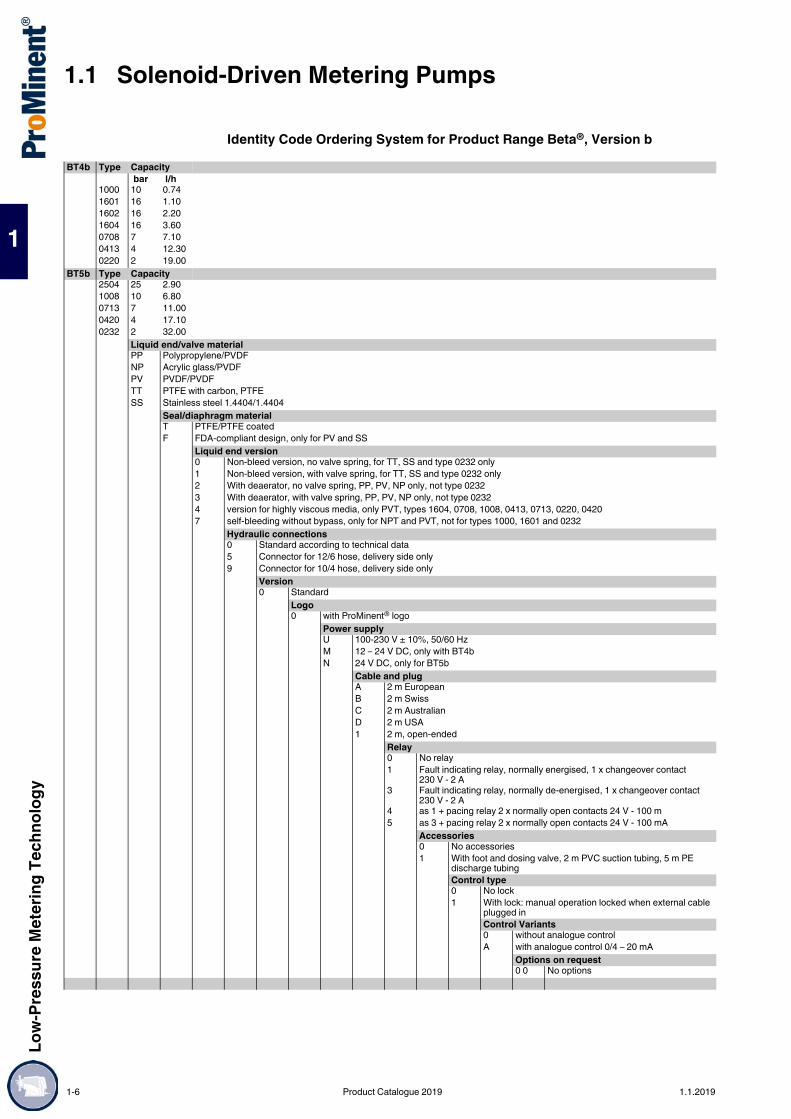
Identity Code Ordering System for Product Range Beta®, Version bBT4b Type Capacity
bar l/h1000 10 0.741601 16 1.101602 16 2.201604 16 3.600708 7 7.100413 4 12.300220 2 19.00
BT5b Type Capacity2504 25 2.901008 10 6.800713 7 11.000420 4 17.100232 2 32.00
Liquid end/valve materialPP Polypropylene/PVDFNP Acrylic glass/PVDFPV PVDF/PVDFTT PTFE with carbon, PTFESS Stainless steel 1.4404/1.4404
Seal/diaphragm materialT PTFE/PTFE coatedF FDA-compliant design, only for PV and SS
Liquid end version0 Non-bleed version, no valve spring, for TT, SS and type 0232 only1 Non-bleed version, with valve spring, for TT, SS and type 0232 only2 With deaerator, no valve spring, PP, PV, NP only, not type 02323 With deaerator, with valve spring, PP, PV, NP only, not type 02324 version for highly viscous media, only PVT, types 1604, 0708, 1008, 0413, 0713, 0220, 04207 self-bleeding without bypass, only for NPT and PVT, not for types 1000, 1601 and 0232
Hydraulic connections0 Standard according to technical data5 Connector for 12/6 hose, delivery side only9 Connector for 10/4 hose, delivery side only
Version0 Standard
Logo0 with ProMinent® logo
Power supplyU 100-230 V ± 10%, 50/60 HzM 12 – 24 V DC, only with BT4bN 24 V DC, only for BT5b
Cable and plugA 2 m EuropeanB 2 m SwissC 2 m AustralianD 2 m USA1 2 m, open-ended
Relay0 No relay1 Fault indicating relay, normally energised, 1 x changeover contact
230 V - 2 A3 Fault indicating relay, normally de-energised, 1 x changeover contact
230 V - 2 A4 as 1 + pacing relay 2 x normally open contacts 24 V - 100 m5 as 3 + pacing relay 2 x normally open contacts 24 V - 100 mA
Accessories0 No accessories1 With foot and dosing valve, 2 m PVC suction tubing, 5 m PE
discharge tubingControl type0 No lock1 With lock: manual operation locked when external cable
plugged inControl Variants0 without analogue controlA with analogue control 0/4 – 20 mA
Options on request0 0 No options
1-6 Product Catalogue 2019 1.1.2019

Low-
Pres
sure
Met
ering
Tech
nolog
y
1.1 Solenoid-Driven Metering Pumps
1
Spare Parts Kits for Solenoid-Driven Metering Pump Beta®
Spare parts kits for Beta® b, consisting of: 1 diaphragm 1 suction valve assembly 1 discharge valve assembly 1 connector kitStainless steel version without suction valve assembly and without discharge valve assembly, with valve seats, seals and valve balls
pk_1_008
Type Wetted materials Order no.Type 1000 PPE 1001644
PPB 1001652NPE 1001713NPB 1001721PPT, NPT, PVT 1023107PVF 1083549TTT 1001737SST 1001729
Type 1601 PPE 1001645PPB 1001653NPE 1001714NPB 1001722PPT, NPT, PVT 1023108PVF 1083547TTT 1001738SST 1001730
Type 1602 PPE 1001646PPB 1001654NPE 1001715NPB 1001723PVT, PPT, NPT 1023109PVF 1083550TTT 1001739SST 1001731
Type 1604 and type 2504 PPE 1039989PPB 1039987NPE 1039988NPB 1039986PVT, PPT, NPT 1035332PVF 1083548PVT HV 1035342TTT 1035330SST 1035331
Type 0708 and type 1008 PPE 1001648PPB 1001656NPE 1001717NPB 1001725PVT, PPT, NPT 1023111PVF 1083564PVT4 1019067TTT 1001741SST 1001733
Type 0413 and type 0713 PPE 1001649PPB 1001657NPE 1001718NPB 1001726PVT, PPT, NPT 1023112PVF 1083551PVT4 1019069TTT 1001742SST 1001734
1.1.2019 Product Catalogue 2019 1-7

1.1 Solenoid-Driven Metering PumpsLo
w-Pr
essu
re M
eter
ing Te
chno
logy
1
Spare Parts Kits for Solenoid-Driven Metering Pump Beta® with Self-Bleeding Dosing HeadSpare parts kits for Beta® with self-bleeding dosing head, consisting of: 1 diaphragm 1 suction valve assembly 1 discharge valve assembly 1 connector kit
Spare Diaphragms for Solenoid-Driven Metering Pump Beta®
Accessories Foot Valves for Low-Pressure Metering Pumps see page → 1-129 Injection Valve for Low-Pressure Metering Pumps see page → 1-134 Hoses and pipework for low-pressure metering pumps see page → 1-157 Suction Lances, Suction Kit Without Level Switch see page → 1-178 Connectors, fittings, connector kits, seals see page → 1-160
Spare Parts Custom Valve Balls/Valve Springs See page → 1-195
Type 0220 and type 0420 PPE 1001650PPB 1001658NPE 1001719NPB 1001727PVT, PPT, NPT 1023113PVF 1083552PVT4 1019070TTT 1001754SST 1001735
Type 0232 PPE 1001651PPB 1001659NPE 1001720NPB 1001728PVT, PPT, NPT 1023124PVF 1083553TTT 1001755SST 1001736
Type Wetted materials Order no.Type 1602 PVT7, NPT7 1047830Type 1604 PVT7, NPT7 1047858Type 0708 and type 1008 PVT7, NPT7 1047832Type 0413 and type 0713 PVT7, NPT7 1047833Type 0220 and type 0420 PVT7, NPT7 1047837
Type Materials in contact with the me-dium
Order no.
Type 1000 all materials 1000244Type 1601 all materials 1000245Type 1602 all materials 1000246Type 1604 and type 2504 all materials 1034612Type 0708 and type 1008 all materials 1000248Type 0413 and type 0713 all materials 1000249Type 0220 and type 0420 all materials 1000250Type 0232 all materials 1000251
Type Wetted materials Order no.
1-8 Product Catalogue 2019 1.1.2019

Low-
Pres
sure
Met
ering
Tech
nolog
y
1.1 Solenoid-Driven Metering Pumps
1
gamma/ X – the proven best-seller intelligently extendedCapacity range 2.3 – 45 l/h, 25 – 2 bar
The new solenoid-driven diaphragm metering pump gamma/ X is user-friendly and has an outstandingly long service life, just like its predecessor. An ingenious solenoid control measures the back pressure and protects the system from overload. This technology makes a pressure sensor superfluous, meaning that operating safety can be significantly increased: no additional parts come into contact with the feed chemical, there are no additional sealing surfaces and no electronic components come into contact with the feed chemical. Whether the metering volume fluctuates or hydraulic failures affect the metering process – the gamma/ X keeps everything at your fingertips.It independently ensures a trouble-free metering process and should the pump ever need maintenance its service module draws attention to this.
Your benefits Simple adjustment of the capacity directly in l/h Direct input of the required final concentration with volume-proportional metering tasks in concentration
mode Integrated pressure measurement and display for greater safety during commissioning and in the
process Virtually wear-free solenoid drive, overload-proof and economical Suitable for continuous micro-metering from approx. 1 ml/h thanks to the regulated solenoid drive Detection of hydraulic malfunctions, such as gas in the dosing head, and no or too high back pressure
ensures smooth processes Bluetooth interface for simple parameter configuration and access to diagnostic data using the Android
gamma/ X app (optional) Adaptation to existing signal transducers by external control via potential-free contacts with pulse step-
up and step-down External control via 0/4-20 mA standard signal with adjustable assignment of signal value to stroke rate
(optional) Integrated 1-month timer for timed metering tasks Guaranteed metering by means of automatic bleeding Connection to process control systems via bus interfaces, such as PROFIBUS®, PROFINET, CAN Bus
and others on request
Technical Details Illuminated LC display and 3-LED display for operating, warning and error messages, visible from all
sides. Factor with external contact control 99:1 - 1:99. Batch operation with max. 99,999 strokes/start pulse. Stroke rate adjustment in 1 stroke/h increments from 1 – 12,000 strokes/h. Continuous electronic stroke length adjustment from 1 - 100 % (recommended 30 - 100 %). Connector for 2-stage level switch. Available material combinations: PP, PVDF, clear acrylic, PTFE and stainless steel. Special dosing head designs for gaseous and high-viscosity media. Degree of protection IP 66 and/or NEMA 4X indoor. Optional 4-20 mA output for remote transmission of stroke length and stroke rate. Universal power supply unit 100 - 230 V, 50/60 Hz. Optional 230 V relay module, can also be retrofitted easily and securely. Optional 24 V combined relay, can also be retrofitted easily and securely.
Field of application Can be integrated into automated processes and used in all industries. The pump can work as a control unit with the timer, for example in cooling water treatment.
1.1.3 Solenoid-Driven Metering Pump gamma/ X
The solenoid-driven diaphragm metering pump gamma incorporates a wealth of eXcellent ingenuity! With integrated pressure measurement, it ensures the smooth running of your metering process. The gamma/ X is ideal for all metering work involving liquid media.
P_GX_001
1.1.2019 Product Catalogue 2019 1-9

1.1 Solenoid-Driven Metering PumpsLo
w-Pr
essu
re M
eter
ing Te
chno
logy
1
Dimensional drawing of gamma/ XMaterial version PPT2
P_G_0055_SW3Dimensional drawing of gamma/ X, Material design PPT – dimensions in mm
Dimensional drawing of gamma/ XMaterial version NPT2
P_G_0056_SW3Dimensional drawing of gamma/ X, Material design NPT – dimensions in mm
Type ∅ A B0245 110 760424, 0220 90 760715, 0414 90 741009, 0708 90 741604 70 711602 70 71
Type C D E0245 - 14 2090424, 0220 110 24 2020715, 0414 107 24 2021009, 0708 108 24 2021604 106 32 1981602 106 32 198
Type ∅ A B0245 110 760424, 0220 90 760715, 0414 90 761009, 0708 90 741604, 2504 70 771602 70 77
Type C D E0245 105 14 2100424, 0220 104 23 2000715, 0414 104 23 2001009, 0708 102 23 2001604, 2504 105 33 1911602 105 33 191
1-10 Product Catalogue 2019 1.1.2019

Low-
Pres
sure
Met
ering
Tech
nolog
y
1.1 Solenoid-Driven Metering Pumps
1
Dimensional drawing of gamma/ XMaterial version PVT2
P_G_0057_SW3Dimensional drawing of gamma/ X, Material design PVT – dimensions in mm
Type ∅ A B0245 110 760424, 0220 90 790715, 0414 90 731009, 0708 90 751604 70 711602 70 71
Type C D E0245 - 14 2090424, 0220 90 25 2030715, 0414 90 25 2031009, 0708 92 25 2031604 84 36 1961602 84 36 196
1.1.2019 Product Catalogue 2019 1-11

1.1 Solenoid-Driven Metering PumpsLo
w-Pr
essu
re M
eter
ing Te
chno
logy
1
Technical Data
All data refers to water at 20 °C.
Materials in Contact With the Medium
Metering reproducibility: ±2% when used according to information in the operating instructionsPermissible ambient temperature: –10 °C to +45 °C
Pump type Delivery rate atmax. back pressure
Stroke rate Connection size o ∅ x i ∅
Suction lift Shipping weight
PP, NP, PV, TT SS bar l/h ml/stroke Strokes/min mm m WC kg kg
gamma/ XGMXa 1602 16 2.3 0.19 200 6 x 4 6.0** 3.6 4.1GMXa 1604 16 3.6 0.30 200 6 x 4 5.0** 3.6 4.1GMXa 0708 7 7.6 0.63 200 8 x 5 4.0** 3.7 5.0GMXa 0414 4 13.5 1.13 200 8 x 5**** 3.0** 3.7 5.0GMXa 0220 2 19.7 1.64 200 12 x 9 2.0** 3.7 5.0GMXa 2504 25 3.8 0.32 200 8 x 4*** 4.0** 4.9 5.5GMXa 1009 10 9.0 0.75 200 8 x 5 3.0** 5.1 6.5GMXa 0715 7 14.5 1.21 200 8 x 5**** 3.0** 5.1 6.5GMXa 0424 4 24.0 2.00 200 12 x 9 3.0** 5.1 6.5GMXa 0245 2 45.0 3.70 200 12 x 9***** 2.0** 5.2 7.0gamma/ X metering pumps with self-bleeding dosing head without bypassGMXa 1602 10 0.9 0.08 200 6 x 4 1.8** 3.6 –GMXa 1604 10 1.6 0.13 200 6 x 4 1.8** 3.6 –GMXa 0708 7 5.7 0.48 200 8 x 5 1.8** 3.7 –GMXa 0414 4 12.0 1.00 200 8 x 5 1.8** 3.7 –GMXa 0220 2 17.4 1.45 200 12 x 9 1.8** 3.7 –GMXa 1009 10 6.0 0.50 200 8 x 5 1.8** 5.1 –GMXa 0715 7 12.9 1.08 200 8 x 5 1.8** 5.1 –GMXa 0424 4 19.2 1.60 200 12 x 9 1.8** 5.1 –
gamma/ X metering pumps with dosing heads for high-viscosity media have a 10 – 20% lower capacity and are not self-priming. G 3/4-DN 10 connector with d 16-DN 10 hose nozzle.
* The given performance data represents guaranteed minimum values, calculated using water as the medium at room temperature.
** Suction lift with a filled dosing head and filled suction line, with a self-bleeding dosing head with air in the suction line
*** with stainless steel design 6 mm connector width**** with stainless steel design 12 mm connector width***** with stainless steel design DN 10
Dosing head Suction/pressure connector Ball seat Seals BallsPPT Polypropylene PVDF PVDF PTFE CeramicNPT Clear acrylic PVDF PVDF PTFE CeramicPVT PVDF PVDF PVDF PTFE CeramicTTT PTFE with carbon PTFE with carbon Ceramic PTFE CeramicSST Stainless steel material
no. 1.4404Stainless steel material no. 1.4404
Ceramic PTFE Ceramic
Mean power consumption: 24/30 WDegree of protection: IP 66, NEMA 4X, insulation class F
Scope of supplyMetering pump with mains cable, connector kit for hose/tube connector as per table.
1-12 Product Catalogue 2019 1.1.2019

Low-
Pres
sure
Met
ering
Tech
nolog
y
1.1 Solenoid-Driven Metering Pumps
1
Identity Code Ordering System for Product Range gamma/ X, Version aGMXa Type Capacity
bar l/h bar l/h bar l/h1602 16 2.3 0220 2 19.7 0715 7 14.51604 16 3.6 2504 25 3.8 0424 4 24.00708 7 7.6 1009 10 9.0 0245 2 45.00414 4 13.5
Liquid end/valve materialPP Polypropylene/PVDFNP Clear acrylic/PVDFPV PVDF/PVDFTT PTFE/PTFESS Stainless steel 1.4404/1.4404
Seal/diaphragm materialT PTFE/PFTE coatedF FDA-compliant design, only for PV and SS
Liquid end version0 Non-bleed version, no valve springonly with NP, TT and SS and type 02451 Non-bleed version, with valve springonly with NP, TT and SS and type 02452 Bleed function, no valve springsonly with PP, PV, NP not for type 02453 Bleed function, with valve springsonly with PP, PV, NP not for type 02454 Version for highly viscous mediaonly with PV, types 1604, 0708, 0414, 1009, 0715, 04247 self-bleeding without bypass, only for NPT and PVT, not for type 0245
Hydraulic connections0 Standard according to technical data5 Discharge side connection for hose 12/6, suction side standard, only with materials PP, NP and PV9 Discharge side connection for hose 10/4, suction side standard , only with materials PP, NP and PV
Diaphragm rupture indicator0 Without diaphragm rupture indicator1 with diaphragm rupture indicator, optical sensor, not for type 0245
Version0 Standard
Logo0 with ProMinent® logo
Power supplyU 100-230 V, ±10%, 50/60 Hz
Cable and plugA 2 m European D 2 m USAB 2 m Swiss E 2 m Great BritainC 2 m Australian 1 2 m, open-ended
Relay, pre-set to0 No relay 1 1 x changeover contact 230 V – 8 A, fault indicating relay N/C4 2 x N/O 24 V – 100 mA, fault indicating relay N/C + pacing relayC 1 x N/O 24 V – 100 mA, fault indicating relay N/C 1 + 4 – 20 mA
outputF with automatic bleed valve 230 V AC, not for pump type 0245G with automatic bleed valve 24 V DC and relay output, not for pump
type 0245Accessories0 No accessories1 With foot valve and discharge valve, 2 m PVC suction
tubing, 5 m PE delivery tubeonly with PP, PV and NP, not with PVT4Control version0 Manual + external with pulse control3 Manual + external with pulse control + analogue
0/4 - 20 mAC as 3 + CANopen*D as 3 + CAN open DULCOMARIN® IIE as 3 + Profinet*R as 3 + PROFIBUS® DP interface M12– *No relay can be selected with these options.
Metering monitor0 Pulse signal input
Remote stop0 without BluetoothB with Bluetooth
LanguageDE GermanEN EnglishFR FrenchES Spanish
1.1.2019 Product Catalogue 2019 1-13

1.1 Solenoid-Driven Metering PumpsLo
w-Pr
essu
re M
eter
ing Te
chno
logy
1
Spare Parts Kit for gamma/ XSpare parts kits for gamma/ X, consisting of: 1 diaphragm 1 suction valve assembly 1 discharge valve assembly 1 connector kitStainless steel version without suction valve assembly and without discharge valve assembly, with valve seats, seals and valve balls
pk_1_008
Type Wetted materials Order no.Type 1602 PPE 1001646
PPB 1001654NPE 1001715NPB 1001723PVT, PPT, NPT 1023109PVF 1083550TTT 1001739SST 1001731
Type 1604 and Type 2504 PPE 1039989PPB 1039987NPE 1039988NPB 1039986PVT, PPT, NPT 1035332PVF 1083548PVT HV 1035342TTT 1035330SST 1035331
Type 0708 and Type 1009 PPE 1001648PPB 1001656NPE 1001717NPB 1001725PVT, PPT, NPT 1023111PVF 1083564PVT HV 1019067TTT 1001741SST 1001733
Type 0414 and Type 0715 PPE 1001649PPB 1001657NPE 1001718NPB 1001726PVT, PPT, NPT 1023112PVF 1083551PVT4 1019069TTT 1001742SST 1001734
Type 0220 and Type 0424 PPE 1051096PPB 1051085NPE 1051118NPB 1051107PVT, PPT, NPT 1051129PVF 1083566PVT HV 1051134TTT 1051151SST 1051139
Type 0245 PPE 1051097PPB 1051086NPE 1051119NPB 1051108PVT, PPT, NPT 1051130PVF 1083567TTT 1051152SST 1074650SSF 1098649
1-14 Product Catalogue 2019 1.1.2019

Low-
Pres
sure
Met
ering
Tech
nolog
y
1.1 Solenoid-Driven Metering Pumps
1
Spare Parts Kits for Solenoid-Driven Metering Pump gamma/ X with Self-Bleeding Dosing HeadSpare parts kits for gamma/ X with self-bleeding dosing head, without bypass, consisting of: 1 diaphragm 1 suction valve assembly 1 discharge valve assembly 1 connector kit
Spare Diaphragms for Solenoid-Driven Metering Pump gamma/ X
Accessories Foot Valves for Low-Pressure Metering Pumps see page → 1-129 Injection Valve for Low-Pressure Metering Pumps see page → 1-134 Hoses and pipework for low-pressure metering pumps see page → 1-157 Suction Lances, Suction Kit Without Level Switch see page → 1-178 Connectors, fittings, connector kits, seals see page → 1-160
Spare Parts Custom Valve Balls/Valve Springs See page → 1-195
Type Wetted materials Order no.Type 1602 PVT7, NPT7 1047830Type 1604 PVT7, NPT7 1047858Type 0708 and Type 1009 PVT7, NPT7 1047832Type 0414 and Type 0715 PVT7, NPT7 1047833Type 0220 and Type 0424 PVT7, NPT7 1051111
Type Materials in contact with the medium
Order no.
Type 1602 all materials 1000246Type 1604 and Type 2504 all materials 1034612Type 0708 and Type 1009 all materials 1000248Type 0414 and Type 0715 all materials 1000249Type 0220 and Type 0424 all materials 1045456Type 0245 all materials 1045443
1.1.2019 Product Catalogue 2019 1-15

1.1 Solenoid-Driven Metering PumpsLo
w-Pr
essu
re M
eter
ing Te
chno
logy
1
gamma/ XL – large output, great featuresCapacity range 8 – 80 l/h, 25 – 2 bar
The new solenoid-driven metering pump gamma/ XL is the enhancement to our proven gamma/ X and covers a capacity range from 8 – 80 l/h at 25 – 2 bar. The gamma/ XL also has other interfaces, for example CAN bus and Wi-Fi connections. This allows the gamma/ XL to network with all systems, devices and platforms. Like the gamma/ X, the gamma/ XL has an intuitive operating concept. The pump is adjusted using a click wheel and 4 additional operating keys. Pressure detection without wetted parts ensures maximum operational safety. Hydraulic error statuses, like “Gas in the dosing head”, “Overpressure” and “No pressure” can be detected.Pressure fluctuations in the system are detected and compensated for, achieving a high level of dosing precision and reducing chemical consumption to the required level.The last 300 events are retrospectively saved in the integral log book, which permits rapid analysis of the cause and troubleshooting.Deviations from the metering volume or hydraulic fault statuses are immediately detected and corrected by the gamma/ XL. The pump’s operating menu includes ordering information for the wear parts required.Designed as a smart product, it can also be connected to our web-based DULCOnneX fluid management platform. The user can use this to monitor his metering process in real time, avoid downtimes and generate reports fully automatically.
Your benefits Simple adjustment of the capacity directly in l/h or in gph Integrated pressure measurement and display for greater safety during commissioning and in the
process Bluetooth and Wi-Fi connection for the simple configuration and call-up of process data (optional) Capacity adjustment range 1:40,000 Direct input of the required final concentration with volume-proportional metering tasks in concentration
mode Virtually wear-free solenoid drive, overload-proof and economical Suitable for continuous micro-metering from approx. 5 ml/h, thanks to the regulated solenoid drive Detection of hydraulic malfunctions, such as gas in the dosing head, and no or too high back pressure,
ensures smooth processes External control via potential-free contacts with pulse step-up and step-down External control via 0/4-20 mA standard signal, scalable Integrated 1-week/1-month timer Guaranteed metering by means of automatic bleeding Connection to process control systems via a BUS interface, such as PROFIBUS®, PROFINET®, CAN
bus or Wi-Fi Automatic mode – volume settings only (l/h, ml/contact etc.) Non-automatic mode – settings via stroke length and stroke rate
Technical Details Illuminated 3” LCD and 3-LED display for operating, warning and error messages, visible from all sides In non-automatic mode, stroke rate setting 1 stroke/h – 12,000 strokes/h, stroke length electronically
continuously variable 0 – 100%, recommended 30 – 100% Factor with external contact control 99:1 – 1:99 Batch operation with max. 99.99 or 99,999 strokes/start pulse Connector for 2-stage level switch 3 additional ports, switched as digital inputs or outputs Optional 0/4 – 20 mA output for remote transmission of stroke length, stroke rate and error messages Optional relay module with 1 x switchover contact, 230 V – 8 A Optional relay module with 2 x On, 24 V – 100 mA
Field of application Chemical distributors Systems engineering Food and beverage industry Potable water Waste water Chemical industry
1.1.4 Solenoid-Driven Metering Pump gamma/ XL
The gamma/ XL is a smart, connectible solenoid-driven metering pump that is setting new standards in terms of productivity, reliability and cost-effectiveness.
1-16 Product Catalogue 2019 1.1.2019

Low-
Pres
sure
Met
ering
Tech
nolog
y
1.1 Solenoid-Driven Metering Pumps
1
Electroplating Bottling processes, e.g. ink cartridges or highlighter pens With an integrated process timer, suitable as a control unit for simple processes, e.g. biocide metering
in cooling water All industrial applications, either as a stand-alone unit or integrated in a complete system
Technical Data
All data refers to water at 20 °C.
Materials in Contact With the Medium
Design of connectors
Diaphragm with PTFE coating.Repeatability of metering ±2% when used in accordance with the operating instructions.Permissible ambient temperature –10 °C to 45 °C.Mean power consumption 78 W.Degree of protection IP 66, insulation class F.
Pump type Max.pressure
Delivery rate Strokevolume
Max.stroke rate
Nominal diameter
Suctionlift
Shipping weight NPE,NPB, PVT / SST
bar l/h ml/stroke Strokes/min m WC kggamma/ XLGXLa 2508 25 8 0.67 200 8 x 4** mm 5* 10/11GXLa 1608 16 8 0.67 200 8 x 5** mm 5* 10/11GXLa 1612 16 12 1 200 8 x 5 mm 6* 10/11GXLa 1020 10 20 1.7 200 12 x 9 mm 5* 10/11GXLa 0730 7 30 2.5 200 12 x 9 mm 5* 10/11GXLa 0450 4 50 4.2 200 G 3/4 - DN 10 3* 10/11GXLa 0280 2 80 6.7 200 G 3/4 - DN 10 2* 10/11gamma/ XL metering pumps with self-bleeding dosing head without bypass*GXLa 1608 16 3.8 0.32 200 8 x 5 mm 1.8 10GXLa 1612 16 6.5 0.54 200 8 x 5 mm 1.8 10GXLa 1020 10 14 1.17 200 12 x 9 mm 1.8 10GXLa 0730 7 28 2.33 200 12 x 9 mm 1.8 10
gamma/ XL metering pumps with dosing heads for higher-viscosity media have a 10 – 20 % lower capacity and are not self-priming. G 3/4 - DN 10 connector with d 16 - DN 10 hose nozzle.
* Suction lift (m WC) = Suction lift with filled dosing head and filled suction line** With stainless steel design 6 mm connector width
Design Dosing head Suction/pressure connector
Ball seat Seals Valve balls
NPT Clear acrylic PVDF PVDF PTFE CeramicPVT PVDF PVDF PVDF PTFE CeramicSST (8 – 12 mm) stainless steel
1.4404stainless steel 1.4404
Ceramic PTFE Ceramic
SST (DN 10) stainless steel 1.4404
stainless steel 1.4404
PTFE with carbon
PTFE Ceramic
Plastic 8 – 12 mm Hose squeeze connectorDN 10 d16 DN 10 hose nozzle
Stainless steel 6 – 12 mm Swagelok systemDN 10 Rp 3/8 insert
Scope of supplyMetering pump with mains cable, connector kit for hose/tube connector as per table.
1.1.2019 Product Catalogue 2019 1-17

1.1 Solenoid-Driven Metering PumpsLo
w-Pr
essu
re M
eter
ing Te
chno
logy
1
Identity Code Ordering System for Product Range gamma/ XLGXLa Regional design
EU EuropeUS USA
Type Capacity bar l/h bar l/h
2508 25 8 0730 7 301608 16 8 0450 4 501612 16 12 0280 2 801020 10 20
Material of dosing head/valvesPV PVDF/PVDF, not for pump type 2508NP Clear acrylic/PVC, only for pump types 2508, 1608, 1612, 1020 and 0730SS stainless steel/stainless steel
Material of seals/diaphragmT only with PV and SSF FDA-compliant design, only for PV and SS
Dosing head design0 without bleed valve, without valve spring, only with material TT and SS1 without bleed valve, with valve spring, only with material TT and SS2 with bleed valve, without valve spring, only with material NP and PV3 with bleed valve, with valve spring, only with material NP and PV4 HV design for higher-viscosity media, only for types 1608, 1612, 1020 and 07307 self-bleeding without bypass, only for types 1608, 1612, 1020 and 0730, only for material NP and PV
Hydraulic connector0 Standard connection in line with technical data5 Connector on discharge side for 12/6 hose, standard on suction side, only with material NP and PVF Connector on discharge side for 8/4 hose, standard on suction side, only with material NP
Diaphragm rupture indicator0 without diaphragm rupture indicator1 with diaphragm rupture indicator, optical sensor2 with dual diaphragm system and diaphragm rupture indicator, pressure sensor, only with material SS
Design0 Housing RAL 5003, cover RAL 2003
Logo0 with ProMinent® logo2 without ProMinent® Logo
Electrical connectionU 100 - 230 V ±10%, 50/60 Hz
Cable and plugA 2 m European D 2 m USA/115 VB 2 m Swiss 1 2 m open endC 2 m Australian
Relay, pre-set to0 no relay1 1 x changeover contact 230 V – 8 A, fault indicating relay N/C4 2 x N/O 24 V – 100 mA, fault indicating relay N/C + pacing relayC 1 x N/O 24 V – 100 mA, fault indicating relay N/C + 4 – 20 mA outputF with automatic bleed valve, 230 V AC, not for pump type 2508G with automatic bleed valve 24 V DC and relay output, not for pump type 2508
Accessories0 no accessories1 with foot and injection valve, 2 m suction line, 5 m discharge line2 as 0 + measuring cup, only for types 2508, 1608, 1612, 1020 and 07303 as 1 + measuring cup, only for types 2508, 1608, 1612, 1020 and 0730
Control version0 Manual + external contact with pulse control3 Manual + external contact with pulse control + analogue 0/4 – 20 mAC as 3 + CANopenE as 3 + PROFINET® interface, M12R as 3 + PROFIBUS® interface, M12
Communication0 without interfaceB with BluetoothW with Wi-Fi module
Operating menu languageDE German FR FrenchEN English ES Spanish
Certification01 CE03 CE + EAC07 MET (USA)
Documentation languageDE German FR FrenchEN English ES Spanish
1-18 Product Catalogue 2019 1.1.2019

Low-
Pres
sure
Met
ering
Tech
nolog
y
1.1 Solenoid-Driven Metering Pumps
1
Spare Parts Kits for Solenoid-Driven Metering Pump gamma/ XLSpare parts kits for gamma/ XL, consisting of: 1 diaphragm 1 suction valve assembly 1 discharge valve assembly 1 connector kitStainless steel version without suction valve assembly and without discharge valve assembly, with valve seats, seals and valve balls
Spare Diaphragms for Solenoid-Driven Metering Pump gamma/ XL
pk_1_008
Type Wetted materials Order no.Type 2508 NPT2 1095912
SST0 1030226NPE 1033172NPB 1033171
Type 1608 PVT2/NPT2 1030225PVF2 1083565PVT7 1047831SST0 1030226NPE 1030620NPB 1030611
Type 1612 PVT2/NPT2 1027081PVF2 1083569PVT4 1019067PVT7 1047832SST0 1027086NPE 1030536NPB 1030525
Type 1020 PVT2/NPT2 1027082PVF2 1083570PVT4 1019069PVT7 1047833SST0 1027087NPE 1030537NPB 1030526
Type 0730 PVT2/NPT2 1095626PVF2 1096089PVT4 1095499PVT7 1095503SST0 1095501NPE 1095701NPB 1095700
Type 0450 PVT2 1095502PVF2 1096090SST0 1095625SSF0 1098651
Type 0280 PVT2 1095500PVF2 1096088SST0 1095624SSF0 1098648
Type Materials in contact with the me-dium
Order no.
Type 2508/1608 all materials 1030353Type 1612 all materials 1000248Type 1020 all materials 1000249Type 0730 all materials 1045456Type 0450 all materials 1045443Type 0280 all materials 1059691
1.1.2019 Product Catalogue 2019 1-19

1.1 Solenoid-Driven Metering PumpsLo
w-Pr
essu
re M
eter
ing Te
chno
logy
1
Accessories Foot Valves for Low-Pressure Metering Pumps see page → 1-129 Injection Valve for Low-Pressure Metering Pumps see page → 1-134 Hoses and pipework for low-pressure metering pumps see page → 1-157 Suction Lances, Suction Kit Without Level Switch see page → 1-178 Connectors, fittings, connector kits, seals see page → 1-160
Spare Parts Custom Valve Balls/Valve Springs See page → 1-195
1-20 Product Catalogue 2019 1.1.2019

Low-
Pres
sure
Met
ering
Tech
nolog
y
1.1 Solenoid-Driven Metering Pumps
1
Volume-proportional Metering of Chlorine Bleach Solution in Potable Water
pk_1_132
Task and requirements Volume-proportional feed of chlorine bleach solution into the main water flow Monitoring of chlorine content after metering
Operating conditions Variable flow Installation in closed buildings
Application information The metered medium emits gas, therefore after a relatively long period of pump idleness, an air (gas)
bubble may have formed in the metering line causing an interruption in metering operation. Metering is to be fully automatic and without malfunctions as operating personnel are not always
present in the waterworks or water supply.
Solution Beta® solenoid-driven metering pump with self-bleeding liquid end Contact water meter in main line for pump activation DULCOMETER® measuring and control technology for final inspection
Benefits High degree of reliability provided by self-bleeding liquid end Reliable protection against overmetering and undermetering with downstream final inspection
1.1.5 Application Examples
Product: Beta@
Metered medium: NaOClSector: Potable waterApplication: Disinfection
1 Beta®/ 4 with self-bleeding dosing head, PMMA/PVC (clear acrylic)
2 Dosing tank3 Suction assembly with foot valve and
level switch4 PVC metering line - soft with woven layer
or PTFE5 Injection valve6 Contact water meter7 Chlorine measuring probe8 Control measurement
1.1.2019 Product Catalogue 2019 1-21

1.1 Solenoid-Driven Metering PumpsLo
w-Pr
essu
re M
eter
ing Te
chno
logy
1
Shock Metering of Biocide in Cooling Water Circuit
pk_1_133
Problems and requirements Increasing the biocide content, possibly in a weekly cycle, leads to the destruction of all biology in the
cooling water. However, this can lead to local increased concentration, which can result in conductance-controlled
bleeding. They disappear again following complete distribution in the cooling water. Therefore, conductance-controlled bleeding needs to be disabled during shock metering and for a
reasonable time thereafter.
Operating conditions Aggressive chemicals (oxidising) Installation of the metering pump in the building
Notes on use Shock metering is done at periodic intervals, e.g. weekly. In smaller cooling circuits, the metering pump with the integral process timer replaces the PLC
Programmable Logic Controller. Conductance-controlled bleeding needs to be disabled via a potential-free contact regardless of the
metering times set. In many cases, bleeding is performed before each shock metering. This bleeding needs to be controlled
by a second relay contact in the pump.
Solution gamma/ X with process timer and the corresponding relay outputs The relays can be assigned to the process timer, if required, and perform the necessary switching
functions. The pump itself meters at the required metering times. Dosing head made of PVDF for high levels of chemical resistance
Benefits Integration of the process timer into the pump results in a high degree of protection of IP65 for the control Cost-saving for a PLC Programmable Logic Controller Saving of installation costs due to contact construction
Product: gamma/ XMetering medium: biocideIndustry: cooling water treatmentApplication: disinfection
1 Metering2 Metering line3 gamma/ L with process timer4 Intake fitting for foot valve and level
switch5 Metering tank6 Relay output for deactivation of
conductivity-controlled desalination during biocide shock metering
7 Conductivity sensor8 D1C conductivity9 Activation – solenoid valve for
desalination10 Waste water
1-22 Product Catalogue 2019 1.1.2019

Low-
Pres
sure
Met
ering
Tech
nolog
y
1.2 Motor-Driven Metering Pumps
1
1.2Motor-Driven Metering Pumps
SG_0039_SW3Pressure [bar] depending on the feed rate [l/h]
ProMinent offers an extensive range of metering pumps with a capacity rating of up to 1,000 l/h. All oscillating positive-displacement pumps feature a leak-free, hermetically sealed metering chamber and an identical operating structure.
Applications General: Chemical metering up to 1,000 l/h Potable water treatment: Metering of disinfectants Cooling circuits: Metering of disinfectants Waste water treatment: Metering of flocculants Paper industry: Metering of additives Plastics production: Metering of additives Textile industry: Metering of dyeing additives Electroplating: Metering of acids/lyes Automotive industry: Metering of cleaning agents Food industry: Metering of solids, concentrates, CIP cleaning agents Pool & Wellness: Metering of disinfectants
Sigma-bCGHR
1.2.1 Selection Guide
1.1.2019 Product Catalogue 2019 1-23

1.2 Motor-Driven Metering PumpsLo
w-Pr
essu
re M
eter
ing Te
chno
logy
1
The smooth operation of metering systems depends not only on choosing the correct model for your application, but also on the correct installation of application-specific accessories. The drawing below illustrates a variety of accessory components, not all of which will be required for every plant, but which give an overview of what can be achieved in practical terms. We are always at your service, to help you choose the right accessories for your processing application, and to provide any additional technical advice (e.g. calculating pipework requirements).
pk_2_000_1_1AK
1.2.2 Installation Options
1 Metering pump2 Activation and control option3 Injection valve4 Shut-off valve5 Flow meter/monitor6 Pulsation damper7 Back pressure valve8 Relief valve in the bypass line9 Level switch10 Foot valve11 Manometer12 System13 Filling14 Bleed valve15 Suction line16 Bypass
1-24 Product Catalogue 2019 1.1.2019

Low-
Pres
sure
Met
ering
Tech
nolog
y
1.2 Motor-Driven Metering Pumps
1
The cost-effective solution for simple applications in the lower performance range.Capacity range 1.0 – 30.6 l/h, 10 – 2 bar
Various pump types are available as a combination of 2 gears and 4 sizes of dosing head in materials PVDF and clear acrylic/PVC, enabling you to match the pump perfectly to your metering process.
Your benefits Precise metering and good suction capacity by soft controlled suction and compression strokes Tough plastic housing – shock-proof and chemical-resistant Suitable for higher viscosity media, thanks to spring-loaded valves Low-noise operation
Technical Details Stroke length adjustment by changing the eccentricity on the pump drive when the pump is idle Stroke length adjustment in 10% steps Diaphragm deflection from the centre position Soft controlled suction and compression strokes
Field of applicationAll low capacity applications where constant metering is required.
Dimensional drawing of the alpha
P_ALP_0006_SW3Dimension drawing of the alpha - dimensions in mm
1.2.3 Motor-Driven Metering Pump alpha
The motor-driven metering pump alpha is the metering pump for liquid media and the optimum solution for simple applications. Robust, low-noise, chemical-resistant, with precise metering and good suction capacity.
P_ALP_0004_SW
1.1.2019 Product Catalogue 2019 1-25

1.2 Motor-Driven Metering PumpsLo
w-Pr
essu
re M
eter
ing Te
chno
logy
1
Technical Data
All data refers to water at 20 °C.
Materials in Contact With the Medium
Metering diaphragm with PTFE coating for all types.FKM = Fluorine Rubber
Motor Data
Pump type Delivery rate atmax. back pressure
Delivery rate atmedium back pressure
Strokerate
Strokelength
Connection sizeo ∅ x i ∅
Suctionlift
Shippingweight
bar l/h ml/stroke
bar l/h ml/stroke
Strokes/min
mm mm m WC kg
50 Hz versionALPc 1001 10 1.0 0.29 5 1.1 0.32 30 2 6 x 4 5.1 3.0ALPc 1002 10 1.8 0.52 5 2.1 0.60 58 2 6 x 4 5.1 3.0ALPc 1004 10 3.5 1.01 5 3.9 1.12 58 3 8 x 5 5.1 3.0ALPc 1008 10 7.7 1.00 5 8.6 1.12 128 3 8 x 5 5.1 3.0ALPc 0707 7 6.9 1.98 3 7.7 2.21 58 3 8 x 5 4.1 3.0ALPc 0417 4 17.0 2.51 2 18.3 2.76 128 3 8 x 5 4.1 3.0ALPc 0230 2 30.6 3.98 1 32.7 4.26 128 3 12 x 9 3.1 3.060 Hz versionALPc 1001 10 1.2 0.29 5 1.3 0.31 36 2 6 x 4 5.1 3.0ALPc 1002 10 2.2 0.53 5 2.6 0.63 69 2 6 x 4 5.1 3.0ALPc 1004 10 4.1 0.99 5 4.7 1.14 69 3 8 x 5 5.1 3.0ALPc 1008 10 8.9 0.96 5 10.4 1.13 154 3 8 x 5 5.1 3.0ALPc 0707 7 8.3 2.00 3 9.2 2.22 69 3 8 x 5 4.1 3.0ALPc 0417 4 20.6 2.45 2 21.9 2.75 154 3 8 x 5 4.1 3.0ALPc 0230 2 34.4 3.72 1 39.2 4.24 154 3 12 x 9 3.1 3.0
Liquid end Suction/discharge connector
Ball seal Seals Balls
PPE Polypropylene Polypropylene EPDM EPDM CeramicPPB Polypropylene Polypropylene FKM FKM CeramicNPE Acrylic glass PVC EPDM EPDM CeramicNPB Acrylic glass PVC FKM FKM CeramicPVT PVDF PVDF PVDF PTFE Ceramic
Type Split pole motor with integrated thermal overload protectionElectrical connection 220-240 V, 50/60 Hz (version A)Power 50 W (at 230 V/50 Hz)Power consumption 0.4 A (at 230 V/50 Hz)
Warranty: The warranties listed under "General Terms and Conditions of Sale" apply, although there is a warranty period of 12 months for the alpha pump drive
1-26 Product Catalogue 2019 1.1.2019

Low-
Pres
sure
Met
ering
Tech
nolog
y
1.2 Motor-Driven Metering Pumps
1
Identity Code Ordering System for Product Range alpha, version c
FKM = Fluorine Rubber
ALPc Type Capacity (50 Hz / 60 Hz) l/h bar l/h bar
1001 1.0 10 1.2 101002 1.8 10 2.2 101004 3.5 10 4.1 101008 7.7 10 8.9 100707 6.9 7 8.3 70417 17.0 4 20.6 40230 30.6 2 34.4 2
Liquid end materialPPE Polypropylene/polypropylene/EPDMPPB Polypropylene/polypropylene/FKMNPE Acrylic/PVC/EPDMNPB Acrylic/PVC/FKMPVT PVDF/PVDF/PTFE
Valve springs2 without valve spring, with bleeding3 with 2 valve springs approx. 0.1 bar, material 1.4571, with bleeding
Hydraulic connectors0 Standard according to technical data
Version0 With ProMinent® logo
Electrical connectionA 230 V, 50/60 Hz, 2 m, Euro. plugB 230 V, 50/60 Hz, 2 m, Swiss plugC 230 V, 50/60 Hz, 2 m, Austral. plug
Accessories0 No ancillary equipment1 with foot and metering valve, 2 m PVC suction line, 5 m PE metering line
1.1.2019 Product Catalogue 2019 1-27

1.2 Motor-Driven Metering PumpsLo
w-Pr
essu
re M
eter
ing Te
chno
logy
1
Spare Parts Kits for Motor-Driven Metering Pump alphaSpare parts kits for alpha, consisting of: 1 diaphragm 1 suction valve assembly 1 discharge valve assembly 1 connector kit
Spare Diaphragms for Motor-Driven Metering Pump alpha
Accessories Foot Valves for Low-Pressure Metering Pumps see page → 1-129 Injection Valve for Low-Pressure Metering Pumps see page → 1-134 Hoses and pipework for low-pressure metering pumps see page → 1-157 Suction Lances, Suction Kit Without Level Switch see page → 1-178 Connectors, fittings, connector kits, seals see page → 1-160
Spare Parts Custom Valve Balls/Valve Springs See page → 1-195
pk_1_008
Type Materials in contact with the medium
Order no.
Type 1001, 1002, 1004, 1008 PPE 1001647PPB 1001655NPE 1001716NPB 1001724PVT 1023110
Type 0707 and type 0417 PPE 1001649PPB 1001657NPE 1001718NPB 1001726PVT 1023112
Type 0230 PPE 1001650PPB 1001658NPE 1001719NPB 1001727PVT 1023113
Type Order no.Type 1001, 1002, 1004, 1008 1000247Type 0707 and type 0417 1000249Type 0230 1000250
1-28 Product Catalogue 2019 1.1.2019

Low-
Pres
sure
Met
ering
Tech
nolog
y
1.2 Motor-Driven Metering Pumps
1
The basic pump for simple applicationsCapacity range 8 – 76 l/h, 10 – 4 bar
With 4 gear reduction ratios, 2 dosing head sizes and 2 dosing head materials, the Vario C motor-driven metering pump is well adapted to basic metering tasks. It is available with a three-phase or single-phase AC motor. Its pump capacity is adjusted via the stroke length, in 1% increments, with a self-locking rotary dial.
Your benefits Excellent suction capacity, gentle metering stroke and consistently precise metering Excellent process quality: Metering reproducibility is better than ± 2% within the stroke length
adjustment range of 30 to 100% Flexible adjustment of the pump capacity by means of the stroke length in 1% increments Fibreglass-reinforced plastic housing Good adaptation to the specific application, thanks to 4 different gear reduction ratios and 2 sizes of
liquid ends in 2 material versions Power end optionally available with three-phase or single-phase AC motor Customised designs are available on request
Technical Details Stroke length: 3 mm Stroke length adjustment range: 0 – 100 % Stroke length adjustment: manually by means of self-locking rotary dial Metering reproducibility is better than ±2% in the 30 – 100% stroke length adjustment range under
defined conditions and with correct installation Wetted materials: PVDF, stainless steel 1.4571/1.4404 DEVELOPAN® diaphragm (single diaphragm with PTFE) Motor: Three-phase AC motor (0.07 KW, 230/400 V, 50/60 Hz) or single-phase AC motor (0.06 kW,
230 V 50 Hz or 115 V 60 Hz) Degree of protection: IP 55 Fibreglass-reinforced plastic housing Provide suitable overload protection in all motor-driven metering pumps during installation for safety
reasons.
Field of application Chemical metering in potable water, cooling and waste water circuits Metering of additives, flocculants etc.
1.2.4 Motor-Driven Metering Pump Vario C
The motor-driven metering pump Vario C delivers a high level of process quality for continuous metering within simple metering tasks. It can be used, for example, in the metering of additives or flocculants in chemical metering.
pk_2_126Vario C
1.1.2019 Product Catalogue 2019 1-29

1.2 Motor-Driven Metering PumpsLo
w-Pr
essu
re M
eter
ing Te
chno
logy
1
Technical Data
The shipping weight of all pump types is 6/7.2 kg (PVDF/SS)
Materials in Contact With the Medium
Motor Data
Motor data sheets can be requested for more information. Motors for Sigma basic pumps, special motors or special motor flanges are available on request.Motors less than 0.75 kW and motors designed for speed-controllable operation are not subject to the IE3 standard in compliance with the Ecodesign Directive 2009/125/EC.
Type VAMc
With 1500 rpm motorat 50 Hz
With 1800 rpm motorat 60 Hz
Suctionlift
Perm. pre-pressure
suction side
Connection, suction/discharge sideDelivery rate at max.
back pressureMax. stroke
rateDelivery rate at max.
back pressureMax. stroke
rate bar l/h ml/
strokeStrokes/
min psi l/h/gph (US) Strokes/min m WC bar G–DN
10008 10 8 4 38 145 9.6/2.5 45 7 2.8 3/4–1010016 10 16 4 77 145 19.2/5.0 92 7 2.8 3/4–1007026 7 26 4 120 100 31.2/8.2 144 7 2.8 3/4–1007042 7 42 4 192 100 50.4/13.3 230 7 2.8 3/4–1007012 7 12 5 38 100 14.4/3.8 45 6 1.7 3/4–1007024 7 24 5 77 100 28.8/7.6 92 6 1.7 3/4–1004039 4 40 5 120 58 48.0/12.6 144 6 1.7 3/4–1004063 4 64 5 192 58 76.8/20.2 230 6 1.7 3/4–10
Material Dosing head Suction/pressure connector
Seals Valve balls Valve seat
PVT PVDF PVDF PTFE Ceramic PTFESST Stainless steel
material no. 1.4404Stainless steel material no. 1.4581
PTFE Stainless steel material no. 1.4404
PTFE
Identity code characteristic
Voltage supply Remarks
S 3 ph, IP 55 220-240 V/380-420 V 50 Hz 0.07 kW250-280 V/440-480 V 60 Hz 0.07 kW
M 1 ph AC, IP 55 230 V ±5% 50/60 Hz 0.06 kWN 1 ph AC, IP 55 115 V ±5% 60 Hz 0.06 kW
1-30 Product Catalogue 2019 1.1.2019

Low-
Pres
sure
Met
ering
Tech
nolog
y
1.2 Motor-Driven Metering Pumps
1
Identity Code Ordering System for Vario Diaphragm Metering Pump
* Digits 1 and 2=back pressure [bar]; digits 3, 4, 5=flow rate [l/h]
VAMc Type* bar l/h
10008 10 810016 10 1607026 7 2607042 7 4207012 7 1207024 7 2404039 4 4004063 4 64
Material Liquid endPVT PVDF, PTFE sealSST stainless steel, PTFE seal
Liquid end version0 no valve spring (standard) PVC1 with 2 valve springs. Hastelloy C4
Hydraulic connection0 standard connection1 PVC union nut and insert2 PP union nut and insert3 PVDF union nut and insert4 Stainless steel union nut and insert5 PP union nut and hose nozzle7 PVDF union nut and hose nozzle8 Stainless steel union nut and hose nozzle
Version0 with ProMinent® logo (standard)1 without ProMinent® logoM modified
Electrical power supplyS 3 ph, 230 V / 400 V; 50/60 HzM 1 ph AC 230 V; AC 50/60 HzN 1 ph AC 115 V; AC 60 Hz
Stroke sensor0 no stroke sensor3 with stroke sensor (Namur)
Stroke length adjustment0 manual (standard)
1.1.2019 Product Catalogue 2019 1-31

1.2 Motor-Driven Metering PumpsLo
w-Pr
essu
re M
eter
ing Te
chno
logy
1
Spare PartsThe spare parts kit generally includes the wear parts for the liquid ends.Scope of delivery with PPE, PCB, PVT material versions: 1 diaphragm 1 suction valve assembly 1 discharge valve assembly 2 valve balls 1 complete sealing set (O-rings or cover rings with PVT design)Scope of delivery with SST material version: 1 diaphragm 2 valve balls 1 complete sealing set (cover rings, flat seals, ball seat)
Spare parts kits for motor-driven metering pump Vario CApplicable to Identity code: Type VAMc 10008, 10016, 07026, 07042
Applicable to Identity code: Type VAMc 07012, 07024, 04039, 04063
Spare diaphragms for motor-driven metering pump Vario C
Accessories Foot Valves for Motor-Driven Metering Pumps see page Injection Valves for Motor-Driven Metering Pumps see page Connectors and Seals for Motor-Driven Metering Pumps see page → 1-189 Suction Lances, Suction Assemblies and Level Switches for Motor-Driven Metering Pumps
see page → 1-183 Speed Controllers see page → 1-203
Spare Parts Custom Accessories See page
Liquid end Materials in contact with the medi-um
Order no.
FM 042 - DN 10 PPE 910753FM 042 - DN 10 PCB 910754FM 042 - DN 10 PVT 1003641FM 042 - DN 10 SST 910751
Liquid end Materials in contact with the medi-um
Order no.
FM 063 - DN 10 PPE 910758FM 063 - DN 10 PCB 910759FM 063 - DN 10 PVT 1003642FM 063 - DN 10 SST 910756
pk_2_105_1
Order no.Vario with FM 042 Type VAMc 10008, 10016, 07026, 07042 811458Vario with FM 063 Type VAMc 07012, 07024, 04039, 04063 811459
1-32 Product Catalogue 2019 1.1.2019

Low-
Pres
sure
Met
ering
Tech
nolog
y
1.2 Motor-Driven Metering Pumps
1
The robust pump for safe and reliable useCapacity range 17 – 144 l/h, 12 – 4 bar
The Sigma/ 1 diaphragm metering pump, together with pumps of type Sigma/ 2 and Sigma/ 3, represents an integrated product range. They cover the capacity range from 17 to 1,030 l/h, with a consistent operating concept, control concept and spare parts management. A wide range of power end versions is available, including some for use in areas at risk from explosion.
Your benefitsExcellent process reliability: In the event of an accident, the feed chemical does not escape to the outside nor into the pump's power
end, thanks to the patented multi-layer safety diaphragm with optical (optionally electric) signalling. Integrated relief valve to protect the pump from overloading. Reliable operation by bleed option during the suction process.Flexible adaptation to the process: The entire Sigma product range is available as standard in a "Physiologically safe in respect of wetted
materials" design. Metering pumps with electro-polished stainless steel metering head enable them to be used in
hygienically challenging applications. Adaptation to specific installation situations, as the "Liquid end on left" option can be selected as
standard. Wide range of power end versions, also for use in ATEX areas and different flange designs for the use
of customised motors. Customised designs are available on request.
Technical Details Stroke length: 4 mm. Stroke length adjustment range: 0 – 100%. Stroke length adjustment: manually by self-locking rotary dial in 1 % increments (optionally with actuator
or control drive). Metering reproducibility is better than ±2% in the 30 – 100% stroke length adjustment range under
defined conditions and with correct installation. Wetted materials: PVDF, stainless steel 1.4571/1.4404, special materials on request. Patented multi-layer safety diaphragm with optical diaphragm rupture display (optionally with
diaphragm rupture warning system via a contact). Integrated hydraulic relief and bleed valve. A wide range of power end versions is available: Three-phase standard motor, 1-phase AC motor,
motors for use in areas at risk from explosion and different flange designs for use in customer-specific motors.
For use in areas at risk from explosion II 2G Ex h IIC T3 Gb X or II 2G Ex h IIC T4 Gb X (optional). Degree of protection IP 55. Fibreglass-reinforced plastic housing. Liquid end on left is available as standard. For reasons of safety, provide suitable overload protection mechanisms when installing all mechanically
deflected diaphragm metering pumps.
Field of application Volume-proportional addition of chemicals in water treatment, e.g. sodium-calcium hypochlorite for the
disinfection of potable water Addition of chemicals depending on the measured value, e.g. metering of acid and alkali for pH
neutralisation in waste water treatment Time-controlled addition of chemicals in the cooling water circuit Pulse-controlled metering in the bottling of different volumes e.g. glycerin filling of manometers
1.2.5 Motor-Driven Metering Pump Sigma/ 1 (Basic type)
The Sigma/ 1 Basic is an extremely robust motor-driven metering pump with patented multi-layer safety diaphragm for excellent process reliability. It offers a wide range of power end designs, such as three-phase or 1-phase AC motors, also for use in areas at risk from explosion.
P_SI_0128_SWSigma/ 1 Basic version
P_SI_0065_C11: Diaphragm rupture sensor
P_SI_0152_SWSigma / 1 liquid end on left
1.1.2019 Product Catalogue 2019 1-33

1.2 Motor-Driven Metering PumpsLo
w-Pr
essu
re M
eter
ing Te
chno
logy
1
Control of Sigma Basic type (S1Ba)Stroke length actuator/controllerActuator:Electronically regulated actuator with contactless position detection for automatic stroke length adjustment, actuating period approx. 1 second for 1% stroke length, return potentiometer 1 kΩ, degree of protection IP 65.Control drive: Electronically regulated actuator with position detection, with no contact with the media, consisting of an actuator and integral servo controller for stroke length adjustment via a standard signal. Standard current input 0/4-20 mA corresponds to stroke length 0 – 100%, switch-over for manual /automatic operation, stroke adjustment in manual mode, electronic stroke length position display, wide-range voltage power unit 85 - 265 V 50/60 Hz, degree of protection Ip65, actual value output 0/4-20 mA for remote display.
Speed controllers with frequency converter (identity code specification Z)The speed control, assembled, consists of a frequency converter and a variable speed motor with 0.09 kW (Sigma 1 Ba), 0.37 kW (Sigma 2 Ba) or 0.55 kW (Sigma 3 Ba).
"Physiologically Safe (FDA) in Respect of Wetted Materials" VersionAll wetted materials in the "Physiologically safe (FDA) in respect of wetted materials" design comply with the FDA guidelines.FDA guidelines: Material PTFE: FDA No. 21 CFR § 177.1550 Material PVDF: FDA No. 21 CFR § 177.2510Available for material version PV and SS.Identity code example: S1BaH04084PV F S000S000
Sigma / 1 Basic Type version "left liquid end "This version offers additional adaptability to special installation situations, e.g. in combination with storage tanks, brackets, etc. Identity code example: S1BaH07042PVTS00 5 S000
P_SI_0152_SWSigma / 1 liquid end on left
1-34 Product Catalogue 2019 1.1.2019

Low-
Pres
sure
Met
ering
Tech
nolog
y
1.2 Motor-Driven Metering Pumps
1
Technical Data
Performance data for TTT, see type PVTMaterials in Contact With the Medium
With "F" sealing material design – "physiologically safe - FDA", the ball seat is made of PVDFMotor Data
Motor data sheets can be requested for more information. Motors for Sigma basic pumps, special motors or special motor flanges are available on request.Motors less than 0.75 kW and motors designed for speed-controllable operation are not subject to the IE3 standard in compliance with the Ecodesign Directive 2009/125/EC.
Information for use in areas at risk from explosionOnly use pumps with the appropriate labelling in line with the ATEX Directive 2014/34/EU in premises at risk from explosion. Ensure that the explosion group, category and degree of protection specified on the label corresponds to or is better than the conditions prevalent in the intended field of application.
Type S1Ba
With 1500 rpm motorat 50 Hz
With 1800 rpm motorat 60 Hz
Suc-tion
lift
Perm. pre-pressure
suction side
Connection, suction/dis-charge side
Ship-ping
weightDelivery rateat max. back
pressure
Max.stroke
rate
Delivery rateat max. back
pressure
Max.stroke
rate bar l/h ml/
strokeStrokes/
min psi l/h/gph (US) Strokes/
min m
WC bar G–DN kg
12017 PVT 10 17 3.8 73 145 20.4/5.3 88 7 1 3/4–10 912017 SST 12 17 3.8 73 174 20.4/5.3 88 7 1 3/4–10 1212035 PVT 10 35 4.0 143 145 42.0/11.0 172 7 1 3/4–10 912035 SST 12 35 4.0 143 174 42.0/11.0 172 7 1 3/4–10 1210050 PVT 10 50 4.0 205 145 60.0/15.8 246 7 1 3/4–10 910050 SST 10 50 4.0 205 145 60.0/15.8 246 7 1 3/4–10 1210022 PVT 10 22 5.0 73 145 26.4/6.9 88 6 1 3/4–10 910022 SST 10 22 5.0 73 145 26.4/6.9 88 6 1 3/4–10 1210044 PVT 10 44 5.1 143 145 52.8/13.9 172 6 1 3/4–10 910044 SST 10 44 5.1 143 145 52.8/13.9 172 6 1 3/4–10 1207065 PVT 7 65 5.2 205 102 78.0/20.6 246 6 1 3/4–10 907065 SST 7 65 5.2 205 102 78.0/20.6 246 6 1 3/4–10 1207042 PVT 7 42 9.5 73 102 50.4/13.3 88 3 1 1–15 1007042 SST 7 42 9.5 73 102 50.4/13.3 88 3 1 1–15 1404084 PVT 4 84 9.7 143 58 100.8/26.6 172 3 1 1–15 1004084 SST 4 84 9.7 143 58 100.8/26.6 172 3 1 1–15 1404120 PVT 4 120 9.7 205 58 144.0/38.0 246 3 1 1–15 1004120 SST 4 120 9.7 205 58 144.0/38.0 246 3 1 1–15 14
Material Dosing head Suction/pressure connector
Seals/ball seat Balls Integral relief valve
PVT PVDF PVDF PTFE/PTFE Ceramic PVDF/FKM or EPDMSST Stainless steel 1.4404 Stainless steel 1.4581 PTFE/PTFE Stainless steel
1.4404Stainless steel/FKM or EPDM
TTT* PTFE + 25% carbon PTFE + 25% carbon PTFE/PTFE Ceramic –
* specifically for areas at risk from explosion
Identity code specification
Power supply Δ/Y Remarks
S 3-phase, IP 55 220 – 240 V/380 – 420 V265 – 280 V/440 – 480 V
50 Hz60 Hz
0.09 kW0.09 kW
T 3-phase, IP 55 220 – 240 V/380 – 420 V265 – 280 V/440 – 480 V
50 Hz60 Hz
0.09 kW0.09 kW
with PTC, speed control range 1:5
R 3-phase, IP 55 220 – 240 V/380 – 420 V 50 Hz 0.09 kW with PTC, speed adjustment range 1:20 with external fan (1-phase 230 V; 50/60 Hz, 20 W)
M 1-phase AC, IP 55 230 V ± 5 % 50/60 Hz 0.12 kWN 1-phase AC, IP 55 115 V ± 5 % 60 Hz 0.12 kWL1 3-phase, II2GEExellT3 220 – 240 V/380 – 420 V 50 Hz 0.12 kWL2 3-phase, II2GEExdllCT4 220 – 240 V/380 – 420 V 50 Hz 0.18 kW with PTC, speed control range 1:5P1 3-phase, II2GEExellT3 250 – 280 V/440 – 480 V 60 Hz 0.12 kWP2 3-phase, II2GEExdllCT4 250 – 280 V/440 – 480 V 60 Hz 0.18 kW with PTC, speed control range 1:5
1.1.2019 Product Catalogue 2019 1-35

1.2 Motor-Driven Metering PumpsLo
w-Pr
essu
re M
eter
ing Te
chno
logy
1
Identity Code Ordering System for Sigma/ 1 Basic Type (S1Ba)
* 10 bar with the PVDF and TTT version.** Standard with tube nozzle in the bypass. Threaded connection on request.*** Internal thread of insert SS DN10-Rp 3/8, DN15-Rp 1/2On request, electropolished dosing heads (≤ Ra 0.8 µm) are available.
S1Ba Drive typeH Main drive, diaphragm
Pump type bar l/h bar l/h
12017 12 17 07065 7 6512035 12 35 07042 7 4210050 10 50 04084 4 8410022 10 22 04120 4 12010044 10 44
Material of liquid endPV PVDF (max. 10 bar)SS Stainless steelTT PTFE + 25% carbon (max. 10 bar)
Seal materialT PTFE sealF FDA-compliant
DiaphragmS Multi-layer safety diaphragm with optical rupture indicatorA Multi-layer safety diaphragm with rupture signalling (contact)
Liquid end version0 No spring1 With 2 valve springs, Hastelloy C, 0.1 bar4** With pressure relief valve, FKM seal, no valve spring, only with PV and SS5** With pressure relief valve, FKM seal with valve springs, only with PV and SS6** With pressure relief valve, EPDM seal, without valve spring, only with PV and SS7** With pressure relief valve, EPDM seal, with valve spring, only with PV and SS
Hydraulic connection0 Standard1 Union nut and PVC insert2 Union nut and PP insert3 Union nut and PVDF insert4 Union nut and SS*** insert7 Union nut and PVDF hose nozzle8 Union nut and SS hose nozzle9 Union nut and stainless steel hose nozzle
Version0 With ProMinent® logo (standard) 1 Without ProMinent® logoM Modified5 Left liquid end
Electrical power supplyS 3 ph, 230 V/400 V 50/60 Hz, 0.09 kWT 3 ph, 230 V/400 V 50/60 Hz, with PTCR Variable speed motor 3 ph, 230/400 V, with PTC, with external fan 1 ph 230 V 50/60 HzZ Speed control compl 1 ph 230 V, 50/60 Hz (variable speed motor + FC)M 1 ph, AC, 230 V/50/60 Hz, 0.09 kWN 1 ph, AC 115 V 60 Hz, 0.09 kWL 3 ph, 230 V/400 V, 50 Hz, (Exe, Exd)P 3 ph, 265 V/440 V, 60 Hz, (Exe, Exd)2 No motor, C 42 flange (NEMA)3 No motor, B 5, size 56 (DIN)
Enclosure rating0 IP 55 (standard)1 Ex-design ATEX-T3 (EX specification: II 2G Ex h IIC T3 Gb X)2 Ex-design ATEX-T4 (EX specification: III 2G Ex h IIC T4 Gb X)
Stroke sensor0 No stroke sensor (standard)2 Pacing relay (reed relay)3 Stroke sensor (Namur) for hazardous locations
Stroke length adjustment0 Manual (standard)1 with servomotor, 85…265 V AC 50/60 Hz3 with stroke control motor 0...20 mA 85…265 V AC 50/60 Hz4 with stroke control motor 4...20 mA 85…265 V AC 50/60 Hz
1-36 Product Catalogue 2019 1.1.2019

Low-
Pres
sure
Met
ering
Tech
nolog
y
1.2 Motor-Driven Metering Pumps
1
Spare PartsThe spare parts kit generally includes the wear parts for the liquid ends.Scope of delivery with PVT material version: 1 diaphragm 2 valves, complete 2 valve balls 2 ball seats 4 composite seals 1 elastomer sealing set (EPDM, FKM-B)Scope of delivery with SST material version: 1 diaphragm 2 valve balls 4 complete sealing sets (cover rings, ball seat discs) 4 composite seals
Spare Parts Kit for Sigma/ 1 for Design With Multi-layer Safety Diaphragm(For identity code: Type 12017, 12035, 10050)
(For identity code: Type 10022, 10044, 07065)
(For identity code: Type 07042, 04084, 04120)
Spare Parts Kits for Sigma/ 1 for Design With Old Diaphragm(For Identity code: Type 12017, 12035, 10050)
(For Identity code: Type 10022, 10044, 07065)
(For Identity code: Type 07042, 04084, 04120)
Liquid end Materials in contact with the medium
Order no.
FM 50 - DN 10 PVT – 1035964FM 50 - DN 10 TTT with 2 valves cpl. 1077570FM 50 - DN 10 SST – 1035966FM 50 - DN 10 SST with 2 valves cpl. 1035965
Liquid end Materials in contact with the medium
Order no.
FM 65 - DN 10 PVT – 1035967FM 65 - DN 10 TTT with 2 valves cpl. 1077571FM 65 - DN 10 SST – 1035969FM 65 - DN 10 SST with 2 valves cpl. 1035968
Liquid end Materials in contact with the medium
Order no.
FM 120 - DN 15 PVT – 1035961FM 120 - DN 15 TTT with 2 valves cpl. 1077572FM 120 - DN 15 SST – 1035963FM 120 - DN 15 SST with 2 valves cpl. 1035962
Liquid end Materials in contact with the medium
Order no.
FM 50 - DN 10 PVT – 1010541FM 50 - DN 10 SST – 1010554FM 50 - DN 10 SST with 2 valves cpl. 1010555
Liquid end Materials in contact with the medium
Order no.
FM 65 - DN 10 PVT – 1010542FM 65 - DN 10 SST – 1010556FM 65 - DN 10 SST with 2 valves cpl. 1010557
Liquid end Materials in contact with the medium
Order no.
FM 120 - DN 15 PVT – 1010543FM 120 - DN 15 SST – 1010558FM 120 - DN 15 SST with 2 valves cpl. 1010559
1.1.2019 Product Catalogue 2019 1-37

1.2 Motor-Driven Metering PumpsLo
w-Pr
essu
re M
eter
ing Te
chno
logy
1
Spare Parts Kit for Sigma/ 1 for FDA Design (Physiologically Safe)(For Identity code: Type 12017, 12035, 10050)
(For Identity code: Type 10022, 10044, 07065)
(For Identity code: Type 07042, 04084, 04120)
Multi-layer Safety Diaphragm (Standard)
Metering Diaphragm (Old Version)
Spare Parts Kits for Integrated Relief ValveConsisting of two compression springs made from Hastelloy C and four FKM-A and EPDM O-rings each
Accessories Foot Valves see page Injection Valves see page Connector Parts, Seals, Hoses see page → 1-189 Suction Lances/Suction Assemblies see page → 1-183 Speed Controllers see page → 1-203 Metering monitor Flow Control set up for motor-driven metering pumps see page → 1-198
Spare Parts Custom Accessories See page
Liquid end Materials in contact with the medium
Order no.
FM 50 - DN 10 PVT – 1046466FM 50 - DN 10 SST without valve 1046468FM 50 - DN 10 SST with valve 1046467
Liquid end Materials in contact with the medium
Order no.
FM 65 - DN 10 PVT – 1046469FM 65 - DN 10 SST without valve 1046471FM 65 - DN 10 SST with valve 1046470
Liquid end Materials in contact with the medium
Order no.
FM 120 - DN 15 PVT – 1046453FM 120 - DN 15 SST without valve 1046465FM 120 - DN 15 SST with valve 1046464
Order no.FM 50 (type 12017; 12035; 10050) 1030114FM 65 (type 10022; 10044; 07065) 1030115FM 120 (type 07042; 04084; 04120) 1035828
Order no.Sigma/ 1 FM 50 (12017; 12035; 10050) 1010279Sigma/ 1 FM 65 (10022; 10044; 07065) 1010282Sigma/ 1 FM 120 (07042; 04084; 04120) 1010285
For material Seals Order no.Spare parts kits for integrated relief valve 4 bar
PVT/SST FKM-A/EPDM 1031199
Spare parts kits for integrated relief valve 7 bar
PVT/SST FKM-A/EPDM 1031200
Spare parts kits for integrated relief valve 10 bar
PVT/SST FKM-A/EPDM 1031201
Spare parts kits for integrated relief valve 12 bar
PVT/SST FKM-A/EPDM 1031202
1-38 Product Catalogue 2019 1.1.2019

Low-
Pres
sure
Met
ering
Tech
nolog
y
1.2 Motor-Driven Metering Pumps
1
The new Sigma X range – reliable, smart and connectibleCapacity range S1Cb: 21 – 117 l/h, 12 – 4 bar
The Sigma X diaphragm metering pump covers a capacity range of 21 to 1,040 l/h in versions S1Cb, S2Cb and S3Cb. Its patented multi-layer safety diaphragm guarantees maximum process reliability. Efficient protection of the power end from overloading by means of an integral frequency converter with microprocessor control(ler).One highlight is the standardised operating concept with click wheel and 4 additional operating keys on a removable operating unit. A large illuminated LCD and a 3-LED display for operating, warning and error messages, visible from all sides, offers additional operating convenience.The Sigma, like all smart ProMinent metering pumps, can be flexibly connected to various bus systems.It has a large adjustment range thanks to a combination of frequency and stroke length adjustment. The pump works with high precision across the entire frequency range. Accurate and complication-free metering of viscous and gaseous media by adjustment of the movement profile.Operating statuses are simply remotely transmitted via an additional output or relay module. A built-in timer, included as standard, controls time-dependent metering cycles.Relevant spare parts can be shown in the display. The integral log book significantly improves process management, optimisation and troubleshooting.
Your benefits Safe: In the event of an accident, the feed chemical does not escape to the outside nor into the pump's
power end, thanks to the patented multi-layer safety diaphragm with optical (optionally electric) signalling.
Integrated relief valve protects the pump against overloading and reliable operation by means of a bleed option during the metering process.
External control is scalable via potential-free contacts with pulse step-up and step-down, batch mode or via a 0/4-20 mA standard signal.
Flexibly connectible: Connection to process management systems via integral PROFIBUS®, CANopen interface.
Integral log book saves up to 300 events and simplifies troubleshooting and analysis of the cause.
Technical Details Stroke length: 4 mm Stroke length adjustment range: 0 – 100% Stroke length adjustment: manually using self-locking rotary dial in 1% increments Metering reproducibility is better than ± 2% in the 30 – 100% stroke length adjustment range under
defined conditions and with correct installation Wetted materials: PVDF, stainless steel 1.4571/1.4404 (special materials on request) Power supply: 1 pH, 100 – 230 V ±10%, 240 V ±6%, 50/60 Hz (220 W) Degree of protection IP 65 Fibreglass-reinforced plastic housing The liquid end on the left of the standard version can be selected for special installation situations or in
combination with storage tanks, brackets etc. Settable manual or external contact mode, factor with external contact control 99:1 – 1:99; batch mode
with max. 99,999 strokes/start pulse. Metering profiles for optimum metering results. Display of wear parts in the Service menu. Connector for 2-stage level switch. Connection to PROFINET using the ProMinent DULCOnvert PROFIBUS®-PROFINET converter. Time-dependent control of the metering volume via integral timer. Relay module with 1 x switchover contact, 230 V – 8 A Relay module with 2 x On, 24 V – 100 mA Output / relay module: 0/4- 20 mA analogue output for remote transmission of the stroke rate plus relay
module with 1 x On, 24 V – 100 mA The Sigma product range is available in a "Physiologically safe in respect of wetted materials" design. Dosing heads with electro-polished stainless steel for aqueous media are available with hygienically
challenging applications. Customised designs are available on request.For reasons of safety, provide suitable overload protection mechanisms when installing all mechanically deflected diaphragm metering pumps.
1.2.6 Motor-Driven Metering Pump Sigma X Control Type – Sigma/ 1 - S1Cb
The Sigma control type is a smart motor-driven metering pump that is setting new standards in terms of productivity, reliability and safety.
P_SI_0201_SWSigma/ 1 control type
1.1.2019 Product Catalogue 2019 1-39
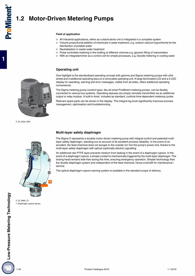
1.2 Motor-Driven Metering PumpsLo
w-Pr
essu
re M
eter
ing Te
chno
logy
1
Field of application All industrial applications, either as a stand-alone unit or integrated in a complete system Volume-proportional addition of chemicals in water treatment, e.g. sodium-calcium hypochlorite for the
disinfection of potable water Neutralisation in waste water treatment Pulse-controlled metering in the bottling of different volumes e.g. glycerin filling of manometers With an integrated timer as a control unit for simple processes, e.g. biocide metering in cooling water
Operating unitOne highlight is the standardised operating concept with gamma and Sigma metering pumps with click wheel and 4 additional operating keys on a removable operating unit. A large illuminated LCD and a 3-LED display for operating, warning and error messages, visible from all sides, offers additional operating convenience.The Sigma metering pump (control type), like all smart ProMinent metering pumps, can be flexibly connected to various bus systems. Operating statuses are simply remotely transmitted via an additional output or relay module. A built-in timer, included as standard, controls time-dependent metering cycles.Relevant spare parts can be shown in the display. The integral log book significantly improves process management, optimisation and troubleshooting.
Multi-layer safety diaphragmThe Sigma X represents a durable motor-driven metering pump with integral control and patented multi-layer safety diaphragm, standing out on account of its excellent process reliability. In the event of an accident, the feed chemical does not escape to the outside nor into the pump's power end, thanks to the multi-layer safety diaphragm with optical (optionally electric) signalling.An additional rear PTFE layer prevents medium from leaking in the event of a diaphragm rupture. In the event of a diaphragm rupture, a simple contact is mechanically triggered by the multi-layer diaphragm. The dosing head remains leak-free during this time, ensuring emergency operation. Simpler technology than the double diaphragm system and independent of the feed chemical, hence a benefit for maintenance / service.The optical diaphragm rupture warning system is available in the standard scope of delivery.
P_SI_0200_SW1
P_SI_0065_C11: Diaphragm rupture sensor
1-40 Product Catalogue 2019 1.1.2019

Low-
Pres
sure
Met
ering
Tech
nolog
y
1.2 Motor-Driven Metering Pumps
1
Metering profilesMetering profiles guarantee optimum metering results by adapting the metering behaviour of the metering pump to the application or chemical used.The combination of frequency and stroke length adjustment permits a large adjustment range, with the pump working with excellent precision over the entire frequency range. Adjustment of the movement profile also guarantees precise and trouble-free metering even with viscous and gaseous media.The stroke motion of the displacement body is continually recorded and regulated so that the stroke is made in line with the desired metering profile. The pump can be operated in normal mode (Diagram 1), with optimised discharge stroke (Diagram 2) or with optimised suction stroke (Diagram 3).Three typical metering profiles are shown schematically with progress over time.
P_SI_010x_SW
"Physiologically safe (FDA) in respect of wetted materials" designAll wetted materials in the "Physiologically safe (FDA) in respect of wetted materials" design comply with the FDA guidelines (Version F).FDA guidelines: Material PTFE: FDA-No. 21 CFR § 177.1550 Material PVDF: FDA-No. 21 CFR § 177.2510Available for material versions PV and SS.Identity code example: S1CbH07042PV F S010S0DE.
Sigma/ X (Control) design "liquid end on left"This version offers additional adaptability to special installation situations, e.g. in combination with storage tanks, brackets, etc.Identity code example: S1CbH07042PVTS01 5 UA1000DE
1 Diagram 1: Discharge stroke, suction stroke equal
2 Diagram 2: long discharge stroke, short suction stroke
3 Diagram 3: short discharge stroke, long suction stroke
P_SI_0199_SWSigma / 1 Control type design, liquid end on left
1.1.2019 Product Catalogue 2019 1-41

1.2 Motor-Driven Metering PumpsLo
w-Pr
essu
re M
eter
ing Te
chno
logy
1
Technical Data
Materials in Contact With the Medium
With "F" sealing material design – "physiologically safe - FDA", the ball seat is made of PVDF
Motor Data
Motors less than 0.75 kW and motors designed for speed-controllable operation are not subject to the IE3 standard in compliance with the Ecodesign Directive 2009/125/EC.
Type S1Cb Delivery rate at max.back pressure
Max.stroke
rate
Delivery rate at max.back pressure
Suctionlift
Perm. pre-pressure
suction side
Connection, suction/discharge side
Shippingweight
bar l/h ml/stroke
Strokes/min
psi gph (US) m WC bar G–DN kg
12017 PVT 10 21 3.8 90 145 5.5 7 1 3/4–10 912017 SST 12 21 3.8 90 174 5.5 7 1 3/4–10 1212035 PVT 10 42 4.0 170 145 11.1 7 1 3/4–10 912035 SST 12 42 4.0 170 174 11.1 7 1 3/4–10 1210050 PVT 10 49 4.0 200 145 12.9 7 1 3/4–10 910050 SST 10 49 4.0 200 145 12.9 7 1 3/4–10 1210022 PVT 10 27 5.0 90 145 7.1 6 1 3/4–10 910022 SST 10 27 5.0 90 145 7.1 6 1 3/4–10 1210044 PVT 10 53 5.1 170 145 14.0 6 1 3/4–10 910044 SST 10 53 5.1 170 145 14.0 6 1 3/4–10 1207065 PVT 7 63 5.2 200 102 16.6 6 1 3/4–10 907065 SST 7 63 5.2 200 102 16.6 6 1 3/4–10 1207042 PVT 7 52 9.5 90 102 13.7 3 1 1–15 1007042 SST 7 52 9.5 90 102 13.7 3 1 1–15 1404084 SST 4 101 9.7 170 58 26.7 3 1 1–15 1404084 PVT 4 101 9.7 170 58 26.7 3 1 1–15 1004120 PVT 4 117 9.7 200 58 30.9 3 1 1–15 1004120 SST 4 117 9.7 200 58 30.9 3 1 1–15 14
Material Dosing head Suction/pressure connector
Seals/ball seat Balls Integral relief valve
PVT PVDF PVDF PTFE/PTFE Ceramic PVDF/FKM or EPDMSST Stainless steel 1.4404 Stainless steel 1.4581 PTFE/PTFE Stainless steel 1.4404 Stainless steel/FKM or EPDM
Identity code specification Power supply RemarksU 1-phase, IP 65 100 – 230 V ±10 % / 240 V ±6 % 50/60 Hz 220 W
1-42 Product Catalogue 2019 1.1.2019

Low-
Pres
sure
Met
ering
Tech
nolog
y
1.2 Motor-Driven Metering Pumps
1
Identity Code Ordering System for the Sigma/ 1 Control Type (S1Cb)
* 10 bar with PVDF version.** Standard with tube nozzle in the bypass. Threaded connection on request.*** Internal thread of insert SS DN10-Rp 3/8, DN15-Rp 1/2**** An HMI order no. 1042550 is required for manual operation, e.g. with the failure of the CAN busOn request, electropolished dosing heads (≤ Ra 0.8 µm) are available.
S1Cb Drive typeH Main power end, diaphragm
Pump type bar l/h
bar l/h
bar l/h
12017 12 21 10022 10 27 07042 7 5212035 12 42 10044 10 53 04084 4 10110050 10 49 07065 7 63 04120 4 117
Dosing head materialPV PVDF (max. 10 bar)SS Stainless steel
Seal materialT PTFE sealF FDA-compliant
Displacement bodyS Multi-layer safety diaphragm with optical rupture indicatorA Multi-layer safety diaphragm with electrical signal
Dosing head version0 no valve spring (standard)1 with 2 valve springs, Hastelloy C; 0.1 bar2 with bleed valve, FKM seal, no valve spring3 with bleed valve, FKM seal, with valve spring4** with relief valve, FPM seal, no valve springs5** with relief valve, FPM seal, with valve springs6** with relief valve, EPDM seal, no valve springs7** with relief valve, EPDM seal, with valve springs8 with bleed valve, EPDM seal, no valve spring9 with bleed valve, EPDM seal, with valve spring
Hydraulic connector0 Standard connection1 Union nut and PVC insert2 Union nut and PP insert3 Union nut and PVDF insert4 Union nut and stainless steel*** insert7 Union nut and PVDF tube nozzle8 Union nut and stainless steel tube nozzle9 Union nut and stainless steel welding sleeve
Version0 With ProMinent® Logo1 Without ProMinent® Logo5 Left liquid end
Electric power supplyU 1 ph, 100 – 230 V ±10%, 240 V ±6%, 50/60 Hz, 110 W
Cable and plugA 2 m Europe C 2 m AustraliaB 2 m Swiss D 2 m USA
Relay0 No relay1 Fault indicating relay (230 V, 8 A)3 Fault indicating relay (24 V, 100 mA) + pacing relay (24 V, 100 mA)8 0/4-20 mA analogue output + fault indicating / pacing relay (24 V - 100 mA)
Control versions0 Manual + external contact with pulse control1 as 0 + analogue + metering profiles
Language 6 as 1 + PROFIBUS® DP interface, M 12DE german 7 as 1 + CANopen (CiA 402, M12 plug), pump without operating unit (HMI) ****EN english Overload switch-offES spanish 0 without overload switch-offFR french Operating unit (HMI)IT Italian 0 Operating unit with Click Wheel (0.5 m cable)NL Dutch 4 Operating unit with Click Wheel + 2 m cablePL Polish 5 Operating unit with Click Wheel + 5 m cablePT Portuguese 6 Operating unit with Click Wheel + 10 m cableCS Czech X without operating unit (HMI)RU Russian Access code
0 without access control1 with access control
1.1.2019 Product Catalogue 2019 1-43

1.2 Motor-Driven Metering PumpsLo
w-Pr
essu
re M
eter
ing Te
chno
logy
1
Spare PartsThe spare parts kit generally includes the wear parts for the liquid ends.Scope of delivery with PVT material version: 1 diaphragm 2 valves, complete 2 valve balls 2 ball seats 4 composite seals 1 elastomer sealing set (EPDM, FKM-B)Scope of delivery with SST material version: 1 diaphragm 2 valve balls 4 complete sealing sets (cover rings, ball seat discs) 4 composite seals
Spare Parts Kit for Sigma/ 1 for Design With Multi-layer Safety Diaphragm(For identity code: Type 12017, 12035, 10050)
(For identity code: Type 10022, 10044, 07065)
(For identity code: Type 07042, 04084, 04120)
Spare Parts Kits for Sigma/ 1 for Design With Old Diaphragm(For Identity code: Type 12017, 12035, 10050)
(For Identity code: Type 10022, 10044, 07065)
(For Identity code: Type 07042, 04084, 04120)
Liquid end Materials in contact with the medium
Order no.
FM 50 - DN 10 PVT – 1035964FM 50 - DN 10 TTT with 2 valves cpl. 1077570FM 50 - DN 10 SST – 1035966FM 50 - DN 10 SST with 2 valves cpl. 1035965
Liquid end Materials in contact with the medium
Order no.
FM 65 - DN 10 PVT – 1035967FM 65 - DN 10 TTT with 2 valves cpl. 1077571FM 65 - DN 10 SST – 1035969FM 65 - DN 10 SST with 2 valves cpl. 1035968
Liquid end Materials in contact with the medium
Order no.
FM 120 - DN 15 PVT – 1035961FM 120 - DN 15 TTT with 2 valves cpl. 1077572FM 120 - DN 15 SST – 1035963FM 120 - DN 15 SST with 2 valves cpl. 1035962
Liquid end Materials in contact with the medium
Order no.
FM 50 - DN 10 PVT – 1010541FM 50 - DN 10 SST – 1010554FM 50 - DN 10 SST with 2 valves cpl. 1010555
Liquid end Materials in contact with the medium
Order no.
FM 65 - DN 10 PVT – 1010542FM 65 - DN 10 SST – 1010556FM 65 - DN 10 SST with 2 valves cpl. 1010557
Liquid end Materials in contact with the medium
Order no.
FM 120 - DN 15 PVT – 1010543FM 120 - DN 15 SST – 1010558FM 120 - DN 15 SST with 2 valves cpl. 1010559
1-44 Product Catalogue 2019 1.1.2019
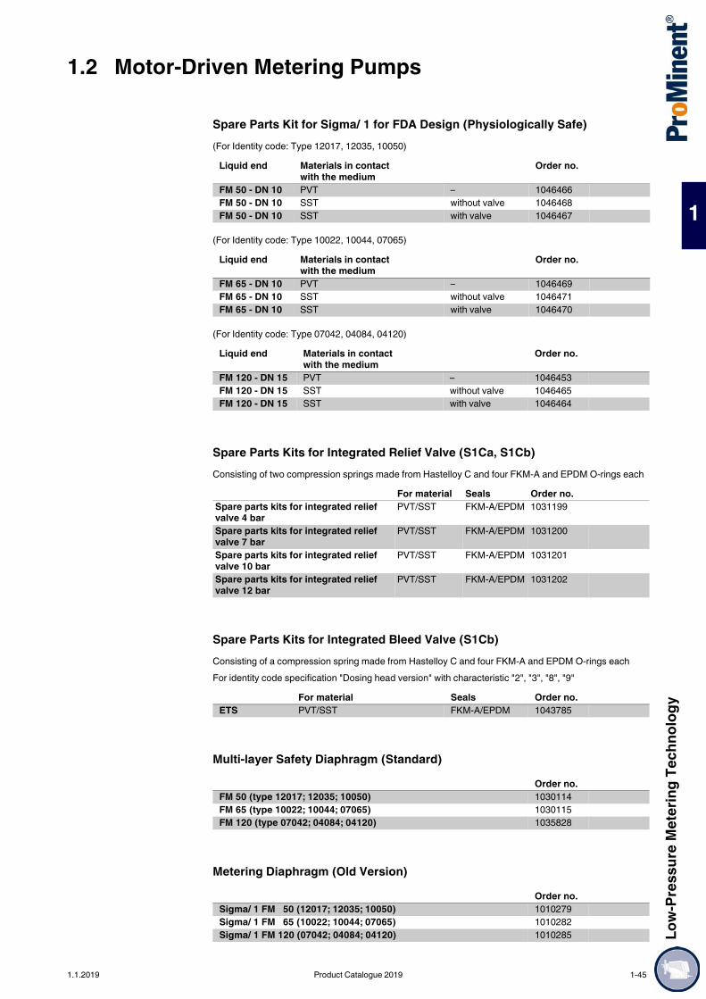
Low-
Pres
sure
Met
ering
Tech
nolog
y
1.2 Motor-Driven Metering Pumps
1
Spare Parts Kit for Sigma/ 1 for FDA Design (Physiologically Safe)(For Identity code: Type 12017, 12035, 10050)
(For Identity code: Type 10022, 10044, 07065)
(For Identity code: Type 07042, 04084, 04120)
Spare Parts Kits for Integrated Relief Valve (S1Ca, S1Cb)Consisting of two compression springs made from Hastelloy C and four FKM-A and EPDM O-rings each
Spare Parts Kits for Integrated Bleed Valve (S1Cb)Consisting of a compression spring made from Hastelloy C and four FKM-A and EPDM O-rings eachFor identity code specification "Dosing head version" with characteristic "2", "3", "8", "9"
Multi-layer Safety Diaphragm (Standard)
Metering Diaphragm (Old Version)
Liquid end Materials in contact with the medium
Order no.
FM 50 - DN 10 PVT – 1046466FM 50 - DN 10 SST without valve 1046468FM 50 - DN 10 SST with valve 1046467
Liquid end Materials in contact with the medium
Order no.
FM 65 - DN 10 PVT – 1046469FM 65 - DN 10 SST without valve 1046471FM 65 - DN 10 SST with valve 1046470
Liquid end Materials in contact with the medium
Order no.
FM 120 - DN 15 PVT – 1046453FM 120 - DN 15 SST without valve 1046465FM 120 - DN 15 SST with valve 1046464
For material Seals Order no.Spare parts kits for integrated relief valve 4 bar
PVT/SST FKM-A/EPDM 1031199
Spare parts kits for integrated relief valve 7 bar
PVT/SST FKM-A/EPDM 1031200
Spare parts kits for integrated relief valve 10 bar
PVT/SST FKM-A/EPDM 1031201
Spare parts kits for integrated relief valve 12 bar
PVT/SST FKM-A/EPDM 1031202
For material Seals Order no.ETS PVT/SST FKM-A/EPDM 1043785
Order no.FM 50 (type 12017; 12035; 10050) 1030114FM 65 (type 10022; 10044; 07065) 1030115FM 120 (type 07042; 04084; 04120) 1035828
Order no.Sigma/ 1 FM 50 (12017; 12035; 10050) 1010279Sigma/ 1 FM 65 (10022; 10044; 07065) 1010282Sigma/ 1 FM 120 (07042; 04084; 04120) 1010285
1.1.2019 Product Catalogue 2019 1-45

1.2 Motor-Driven Metering PumpsLo
w-Pr
essu
re M
eter
ing Te
chno
logy
1
Spare Parts Kits for Integrated Relief ValveConsisting of two compression springs made from Hastelloy C and four FKM-A and EPDM O-rings each
Protective cowlingProtection of the operating unit (HMI) of Sigma metering pumps against contamination; made from transparent silicone rubber. For Sigma X control types S1Cb, S2Cb and S3Cb.
Wall bracketWall bracket with operating lever for wall mounting of the operating unit (HMI) without any fittings. For Sigma control types S1Cb / S2Cb / S3Cb.
Extension cable for operating unit (HMI)
Accessories of CANopen operationAn operating unit is needed for the manual operation of a CANopen pump.
Accessories Foot Valves see page Injection Valves see page Connector Parts, Seals, Hoses see page → 1-189 Suction Lances/Suction Assemblies see page → 1-183 Speed Controllers see page → 1-203 Metering monitor Flow Control set up for motor-driven metering pumps see page → 1-198
Spare Parts Custom Accessories See page
For material Seals Order no.Spare parts kits for integrated relief valve 4 bar
PVT/SST FKM-A/EPDM 1031199
Spare parts kits for integrated relief valve 7 bar
PVT/SST FKM-A/EPDM 1031200
Spare parts kits for integrated relief valve 10 bar
PVT/SST FKM-A/EPDM 1031201
Spare parts kits for integrated relief valve 12 bar
PVT/SST FKM-A/EPDM 1031202
Order no.Protective cowling for operating unit (S1Cb, S2Cb, S3Cb) 1083680
Order no.Wall bracket for operating unit (S1Cb, S2Cb, S3Cb) 1036683
Order no.Connecting cable - CAN M12 5-pole 1 m 1022139Connecting cable - CAN M12 5-pole 2 m 1022140Connecting cable - CAN M12 5-pole 5 m 1022141Connecting cable - CAN M12 5-pin. 10 m 1046383
Order no.Operating unit (HMI) Sigma X - S1Cb 1092956
1-46 Product Catalogue 2019 1.1.2019
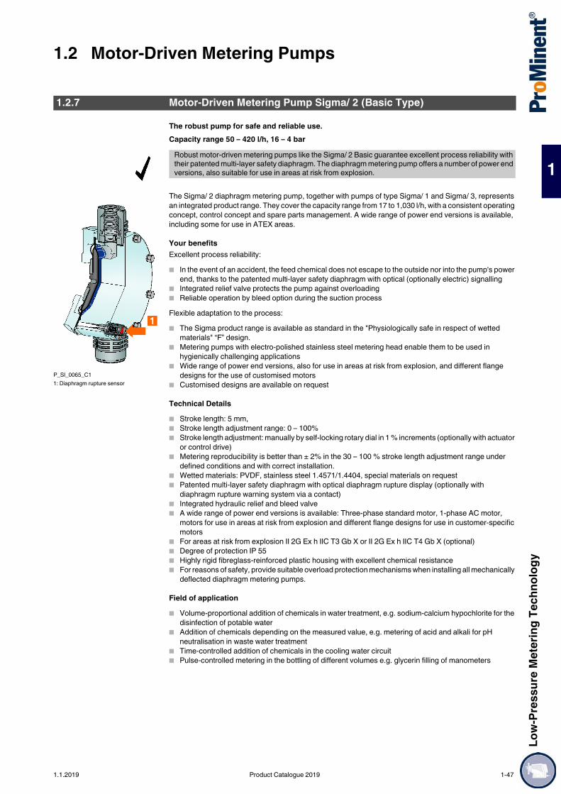
Low-
Pres
sure
Met
ering
Tech
nolog
y
1.2 Motor-Driven Metering Pumps
1
The robust pump for safe and reliable use.Capacity range 50 – 420 l/h, 16 – 4 bar
The Sigma/ 2 diaphragm metering pump, together with pumps of type Sigma/ 1 and Sigma/ 3, represents an integrated product range. They cover the capacity range from 17 to 1,030 l/h, with a consistent operating concept, control concept and spare parts management. A wide range of power end versions is available, including some for use in ATEX areas.
Your benefitsExcellent process reliability: In the event of an accident, the feed chemical does not escape to the outside nor into the pump's power
end, thanks to the patented multi-layer safety diaphragm with optical (optionally electric) signalling Integrated relief valve protects the pump against overloading Reliable operation by bleed option during the suction processFlexible adaptation to the process: The Sigma product range is available as standard in the "Physiologically safe in respect of wetted
materials" “F” design. Metering pumps with electro-polished stainless steel metering head enable them to be used in
hygienically challenging applications Wide range of power end versions, also for use in areas at risk from explosion, and different flange
designs for the use of customised motors Customised designs are available on request
Technical Details Stroke length: 5 mm, Stroke length adjustment range: 0 – 100% Stroke length adjustment: manually by self-locking rotary dial in 1 % increments (optionally with actuator
or control drive) Metering reproducibility is better than ± 2% in the 30 – 100 % stroke length adjustment range under
defined conditions and with correct installation. Wetted materials: PVDF, stainless steel 1.4571/1.4404, special materials on request Patented multi-layer safety diaphragm with optical diaphragm rupture display (optionally with
diaphragm rupture warning system via a contact) Integrated hydraulic relief and bleed valve A wide range of power end versions is available: Three-phase standard motor, 1-phase AC motor,
motors for use in areas at risk from explosion and different flange designs for use in customer-specific motors
For areas at risk from explosion II 2G Ex h IIC T3 Gb X or II 2G Ex h IIC T4 Gb X (optional) Degree of protection IP 55 Highly rigid fibreglass-reinforced plastic housing with excellent chemical resistance For reasons of safety, provide suitable overload protection mechanisms when installing all mechanically
deflected diaphragm metering pumps.
Field of application Volume-proportional addition of chemicals in water treatment, e.g. sodium-calcium hypochlorite for the
disinfection of potable water Addition of chemicals depending on the measured value, e.g. metering of acid and alkali for pH
neutralisation in waste water treatment Time-controlled addition of chemicals in the cooling water circuit Pulse-controlled metering in the bottling of different volumes e.g. glycerin filling of manometers
1.2.7 Motor-Driven Metering Pump Sigma/ 2 (Basic Type)
Robust motor-driven metering pumps like the Sigma/ 2 Basic guarantee excellent process reliability with their patented multi-layer safety diaphragm. The diaphragm metering pump offers a number of power end versions, also suitable for use in areas at risk from explosion.
P_SI_0065_C11: Diaphragm rupture sensor
1.1.2019 Product Catalogue 2019 1-47

1.2 Motor-Driven Metering PumpsLo
w-Pr
essu
re M
eter
ing Te
chno
logy
1
Sigma Basic Type Control Functions (S2Ba)Stroke length actuator/controllerActuator:Electronically regulated actuator with contactless position detection for automatic stroke length adjustment, actuating period approx. 1 second for 1% stroke length, return potentiometer 1 kΩ, degree of protection IP 65.Control drive: Electronically regulated actuator with position detection, with no contact with the media, consisting of an actuator and integral servo controller for stroke length adjustment via a standard signal. Standard current input 0/4-20 mA corresponds to stroke length 0 – 100%, switch-over for manual /automatic operation, stroke adjustment in manual mode, electronic stroke length position display, wide-range voltage power unit 85 - 265 V 50/60 Hz, degree of protection Ip65, actual value output 0/4-20 mA for remote display.
Speed controllers with frequency converter (identity code specification Z)The speed controller assembly consists of a frequency converter and a variable speed motor of 0.37 kW.
"Physiologically Safe (FDA) in Respect of Wetted Materials" VersionAll wetted materials in the "Physiologically safe (FDA) in respect of wetted materials" design comply with the FDA guidelines.FDA guidelines: Material PTFE: FDA-No. 21 CFR § 177.1550 Material PVDF: FDA-No. 21 CFR § 177.2510Available for material version PV and SS.Identity code example: S2BaHM07220PV F S000S000
1-48 Product Catalogue 2019 1.1.2019

Low-
Pres
sure
Met
ering
Tech
nolog
y
1.2 Motor-Driven Metering Pumps
1
Technical Data
Performance data for TTT, see type PVT
Materials in Contact With the Medium
With "F" sealing material design – "physiologically safe - FDA", the ball seat is made of PVDF
Motor Data
Motor data sheets can be requested for more information. Motors for Sigma basic pumps, special motors or special motor flanges are available on request.Motors less than 0.75 kW and motors designed for speed-controllable operation are not subject to the IE3 standard in compliance with the Ecodesign Directive 2009/125/EC.
Information for use in areas at risk from explosionOnly use pumps with the appropriate labelling in line with the ATEX Directive 2014/34/EU in premises at risk from explosion. Ensure that the explosion group, category and degree of protection specified on the label corresponds to or is better than the conditions prevalent in the intended field of application.
Type S2Ba
With 1500 rpm motor at 50 Hz With 1800 rpm motor at 60 Hz Suctionlift
Perm. pre-pressure
suction side
Connection suction/dis-charge side
Ship-ping
weightDelivery rateat max.
back pressure
Max.stroke
rate
Delivery rateat max.
back pressure
Max.stroke
rate bar l/h ml/
strokeStrokes/
min psi l/h/gph (US) Strokes/
min m WC bar G–DN kg
16050 PVT 10 50 11.4 73 145 60.0/15.8 87 7 3 1–15 1516050 SST 16 47 11.4 73 232 56.0/14.7 87 7 3 1–15 2016090 PVT 10 88 11.4 132 145 106.0/28.0 158 7 3 1–15 1516090 SST 16 82 11.4 132 232 98.4/25.9 158 7 3 1–15 2016130 PVT 10 135 10.9 198 145 156.0/41.2 238 7 3 1–15 1516130 SST 16 124 10.9 198 232 148.0/39.0 238 7 3 1–15 2007120 PVT 7 126 27.4 73 102 150.0/39.6 87 5 1 1 1/2–25* 1607120 SST 7 126 27.4 73 102 150.0/39.6 87 5 1 1 1/2–25* 2407220 PVT 7 220 27.7 132 102 264.0/69.7 158 5 1 1 1/2–25* 1607220 SST 7 220 27.7 132 102 264.0/69.7 158 5 1 1 1/2–25* 2404350 PVT 4 350 29.4 198 58 420.0/110.9 238 5 1 1 1/2–25* 1604350 SST 4 350 29.4 198 58 420.0/110.9 238 5 1 1 1/2–25* 24
* With Sigma types 07120, 07220 and 04350, the dosing head is fitted with DN 25 (G 1 1/2) valves. As DN 20 is generally sufficient for these types of pipes (see technical data, suction/discharge side connector), the connector parts that can be ordered under the identity code (e.g. inserts) are already reduced to DN 20, i.e. piping and accessories can be installed in DN 20.
Material Dosing head Suction/pressure connector
Seals/ball seat Balls Integral relief valve
PVT PVDF PVDF PTFE/PTFE Ceramic/glass* PVDF/FKM or EPDMSST Stainless steel 1.4404 Stainless steel 1.4581 PTFE/PTFE Stainless steel 1.4404 Stainless steel/FKM or EPDMTTT** PTFE + 25% carbon PTFE + 25% carbon PTFE/PTFE Ceramic/glass* –
* with 07120, 07220, 04350** specifically for areas at risk from explosion
Identity code specification
Power supply Δ/Y Remarks
S 3-phase, IP 55 220 – 240 V/380 – 420 V220 – 280 V/440 – 480 V
50 Hz60 Hz
0.25 kW0.25 kW
T 3-phase, IP 55 220 – 240 V/380 – 420 V220 – 280 V/440 – 480 V
50 Hz60 Hz
0.25 kW with PTC, speed control range 1:5
R 3-phase, IP 55 220 – 240 V/380 – 420 V 50 Hz 0.37 kW with PTC, speed adjustment range 1:20 with external fan (1-phase 230 V; 50/60Hz, 134 W)
M 1-phase AC, IP 55 230 V ± 5 % 50/60 Hz 0.18 kWN 1-phase AC, IP 55 115 V ± 5 % 60 Hz 0.18 kWL1 3-phase, II2GEExellT3 220 – 240 V/380 – 420 V 50 Hz 0.18 kWL2 3-phase, II2GEExdllCT4 220 – 240 V/380 – 420 V 50 Hz 0.18 kW with PTC, speed control range 1:5P1 3-phase, II2GEExellT3 250 – 280 V/440 – 480 V 60 Hz 0.18 kWP2 3-phase, II2GEExdllCT4 250 – 280 V/440 – 480 V 60 Hz 0.21 kW with PTC, speed control range 1:5
1.1.2019 Product Catalogue 2019 1-49

1.2 Motor-Driven Metering PumpsLo
w-Pr
essu
re M
eter
ing Te
chno
logy
1
Identity Code Ordering System for Sigma/ 2 Basic Type (S2Ba)
* 10 bar with the PVDF and TTT version.** Standard with tube nozzle in the bypass. Threaded connection on request.*** Internal thread of the insert SS DN15-Rp 1/2, DN25/20-G 3/4On request, electropolished dosing heads (≤ Ra 0.8 µm) are available.
S2Ba Drive typeHM Main drive, diaphragm
Pump typebar l/h bar l/h
16050 16 47 07120 7 12616090 16 82 07220 7 22016130 16 124 04350 4 350
Liquid end materialPV PVDF (max. 10 bar)SS Stainless steelTT PTFE + 25% carbon (max. 10 bar)
Seal materialT PTFE sealF FDA-compliant
DiaphragmS Multi-layer safety diaphragm with optical rupture indicatorA Multi-layer safety diaphragm with rupture signalling (contact)
Liquid end version0 No spring1 With 2 valve springs, Hastelloy C4, 0.1 bar4** With pressure relief valve, FKM seal, no valve spring, only with PV and SS5** With pressure relief valve, FKM seal with valve springs, only with PV and SS6** With pressure relief valve, EPDM seal, without valve spring, only with PV and SS7** With pressure relief valve, EPDM seal, with valve spring, only with PV and SS
Hydraulic connection0 Standard1 Union nut and PVC insert2 Union nut and PP insert3 Union nut and PVDF insert4 Union nut and SS*** insert7 Union nut and PVDF hose nozzle8 Union nut and SS hose nozzle9 Union nut and stainless steel hose nozzle
Version0 With ProMinent® logo (standard)1 Without ProMinent® logoM Modified
Electrical power supplyS 3 ph, 230 V/400 V 50/60 HzT 3 ph, 230 V/400 V 50/60 Hz, with PTCR Variable speed motor 3 ph, 230/400 V, with PTC, with external fan 1 ph 230 V 50/60 HzZ Speed control compl 1 ph 230 V, 50/60 Hz (variable speed motor + FC)M 1 ph, AC, 230 V/50/60 HzN 1 ph, AC, 115 V, 60 HzL 3 ph, 230 V/400 V, 50 Hz, (Exe, Exd)P 3 ph, 265 V/440 V, 60 Hz, (Exe, Exd)1 No motor, with B14 flange, Gr. 71 DIN2 No motor, with flange NEMA 56 C3 No motor, with B5 flange, Gr. 63 DIN
Enclosure rating0 IP 55 (standard)1 Ex-design ATEX-T3 (EX specification: II 2G Ex h IIC T3 Gb X)2 Ex-design ATEX-T4 (EX specification: III 2G Ex h IIC T4 Gb X)
Stroke sensor0 No stroke sensor (standard)2 Pacing relay (reed relay)3 Stroke sensor (Namur) for hazardous locations
Stroke length adjustment0 Manual (standard)1 with servomotor, 85…265 V AC 50/60 Hz3 with stroke control motor 0...20 mA 85…265 V AC 50/60 Hz4 with stroke control motor 4...20 mA 85…265 V AC 50/60 Hz
1-50 Product Catalogue 2019 1.1.2019

Low-
Pres
sure
Met
ering
Tech
nolog
y
1.2 Motor-Driven Metering Pumps
1
Spare PartsThe spare parts kit generally includes the wear parts for the liquid ends.Scope of delivery with PVT material version: 1 diaphragm 2 valves, complete 2 valve balls 2 ball seats 4 composite seals 1 elastomer sealing set (EPDM, FKM-B)Scope of delivery with SST material version: 1 diaphragm 2 valve balls 2 ball seat discs 4 composite seals
Spare Parts Kit for Sigma/ 2 for Design With Multi-layer Safety Diaphragm(Applies to identity code types 16050, 16090, 16130, 12050, 12090 and 12130)
(Applies to identity code types 07120, 07220 and 04350)
Spare Parts Kits for Sigma/ 2 for Design With Old Diaphragm(Applies to identity code types 16050, 16090, 16130, 12050, 12090 and 12130)
(Applies to identity code types 07120, 07220 and 04350)
Liquid end Materials in contact with the medium
Order no.
FM 130 - DN 15 PVT – 1035951FM 130 - DN 15 TTT with 2 valves cpl. 1077573FM 130 - DN 15 SST – 1035957FM 130 - DN 15 SST with 2 valves cpl. 1035954
Liquid end Materials in contact with the medium
Order no.
FM 350 - DN 25 PVT – 1035953FM 350 - DN 25 TTT with 2 valves cpl. 1077574FM 350 - DN 25 SST – 1035960FM 350 - DN 25 SST with 2 valves cpl. 1035959
Liquid end Materials in contact with the medium
Order no.
FM 130 - DN 15 PVT – 740324FM 130 - DN 15 SST – 740326FM 130 - DN 15 SST with 2 valves cpl. 740328
Liquid end Materials in contact with the medium
Order no.
FM 350 - DN 25 PVT – 740325FM 350 - DN 25 SST – 740327FM 350 - DN 25 SST with 2 valves cpl. 740329
1.1.2019 Product Catalogue 2019 1-51

1.2 Motor-Driven Metering PumpsLo
w-Pr
essu
re M
eter
ing Te
chno
logy
1
Spare Parts Kits for Sigma/ 2 With FDA Design (Physiologically Safe)(Applies to identity code types 16050, 16090, 16130, 12050, 12090 and 12130)
(Applies to identity code types 07120, 07220 and 04350)
Multi-layer Safety Diaphragm (Standard)
Metering Diaphragm (Old Version)
Spare Parts Kits for Integrated Relief ValveConsisting of two compression springs made from Hastelloy C and four FKM-A and EPDM O-rings each
Gear Oil
Accessories Foot Valves see page Injection Valves see page Connector Parts, Seals, Hoses see page → 1-189 Suction Lances/Suction Assemblies see page → 1-183 Speed Controllers see page → 1-203 Metering monitor Flow Control set up for motor-driven metering pumps see page → 1-198
Spare Parts Custom Accessories See page
Liquid end Materials in contact with the medium
Order no.
FM 130 - DN 15 PVT – 1046472FM 130 - DN 15 SST without valve 1046473FM 130 - DN 15 SST with valve 1046474
Liquid end Materials in contact with the medium
Order no.
FM 350 - DN 25 PVT – 1046475FM 350 - DN 25 SST without valve 1046476FM 350 - DN 25 SST with valve 1046477
Order no.FM 130 (type: 16050, 16090, 16130) 1029771FM 350 (type: 07120, 07220, 04350) 1033422
Order no.Sigma with FM 130 identity code: Type 16050, 16090, 16130 792495Sigma with FM 350 identity code: Type 07120, 07220, 04350 792496
For material Seals Order no.Spare parts kits for integrated relief valve 4 bar
PVT/SST FKM-A/EPDM 1031199
Spare parts kits for integrated relief valve 7 bar
PVT/SST FKM-A/EPDM 1031200
Spare parts kits for integrated relief valve 10 bar
PVT FKM-A/EPDM 1031201
Spare parts kit for relief valve 16 bar SST FKM-A/EPDM 1031203
Volume Order no. l
Mobilgear 634 VG 460 gear oil 1 1004542
1-52 Product Catalogue 2019 1.1.2019

Low-
Pres
sure
Met
ering
Tech
nolog
y
1.2 Motor-Driven Metering Pumps
1
The new Sigma X range – reliable, smart and connectibleCapacity range S2Cb: 61 – 353 l/h, 16 – 4 bar
The Sigma X diaphragm metering pump covers a capacity range of 21 to 1,040 l/h in versions S1Cb, S2Cb and S3Cb. Its patented multi-layer safety diaphragm guarantees maximum process reliability. Efficient protection of the power end from overloading by means of an integral frequency converter with microprocessor control(ler).One highlight is the standardised operating concept with click wheel and 4 additional operating keys on a removable operating unit. A large illuminated LCD and a 3-LED display for operating, warning and error messages, visible from all sides, offers additional operating convenience.The Sigma, like all smart ProMinent metering pumps, can be flexibly connected to various bus systems.It has a large adjustment range thanks to a combination of frequency and stroke length adjustment. The pump works with high precision across the entire frequency range. Accurate and complication-free metering of viscous and gaseous media by adjustment of the movement profile.Operating statuses are simply remotely transmitted via an additional output or relay module. A built-in timer, included as standard, controls time-dependent metering cycles.Relevant spare parts can be shown in the display. The integral log book significantly improves process management, optimisation and troubleshooting.
Your benefits Safe: In the event of an accident, the feed chemical does not escape to the outside nor into the pump's
power end, thanks to the patented multi-layer safety diaphragm with optical (optionally electric) signalling.
Integrated overload shut-down in the pump control to protect the pump from overloading and thus significantly reduce pressure surges caused by blockages.
External control is scalable via potential-free contacts with pulse step-up and step-down, batch mode or via a 0/4-20 mA standard signal.
Flexibly connectible: Connection to process management systems via integral PROFIBUS®, CANopen interface.
Integral log book saves up to 300 events and simplifies troubleshooting and analysis of the cause.
Technical Details Stroke length: 5 mm Stroke length adjustment range: 0 – 100% Stroke length adjustment: manually using self-locking rotary dial in 1% increments Metering reproducibility is better than ± 2% in the 30 – 100% stroke length adjustment range under
defined conditions and with correct installation Power supply: 1 pH, 100 – 230 V ±10%, 240 V ±6%, 50/60 Hz (110 W) Degree of protection IP 65 Fibreglass-reinforced plastic housing Settable manual or external contact mode, factor with external contact control 99:1 – 1:99; batch mode
with max. 99,999 strokes/start pulse. Display of wear parts in the Service menu. Connector for 2-stage level switch. Connection to PROFINET using the ProMinent DULCOnvert PROFIBUS®-PROFINET converter. Time-dependent control of the metering volume via integral timer. Relay module with 1 x switchover contact, 230 V – 8 A Relay module with 2 x On, 24 V – 100 mA Output / relay module: 0/4- 20 mA analogue output for remote transmission of the stroke rate plus relay
module with 1 x On, 24 V – 100 mA The Sigma product range is available in a "Physiologically safe in respect of wetted materials" design. Wetted materials: PVDF, stainless steel 1.4571/1.4404, special materials on request Dosing heads with electro-polished stainless steel are available for aqueous media with hygienically
demanding applications. Customised designs are available on request.For reasons of safety, provide suitable overload protection mechanisms when installing all mechanically
deflected diaphragm metering pumps.
1.2.8 Motor-Driven Metering Pump Sigma X Control Type – Sigma/ 2 - S2Cb
The Sigma control type is a smart motor-driven metering pump that is setting new standards in terms of productivity, reliability and safety.
P_SI_0202_SWSigma/ 2 control type
P_SI_0200_SW1
1.1.2019 Product Catalogue 2019 1-53

1.2 Motor-Driven Metering PumpsLo
w-Pr
essu
re M
eter
ing Te
chno
logy
1
Field of application All industrial applications, either as a stand-alone unit or integrated in a complete system Volume-proportional addition of chemicals in water treatment, e.g. sodium-calcium hypochlorite for the
disinfection of potable water Neutralisation in waste water treatment Pulse-controlled metering in the bottling of different volumes e.g. glycerin filling of manometers With an integrated timer as a control unit for simple processes, e.g. biocide metering in cooling water
Operating unitOne highlight is the standardised operating concept with gamma and Sigma metering pumps with click wheel and 4 additional operating keys on a removable operating unit. A large illuminated LCD and a 3-LED display for operating, warning and error messages, visible from all sides, offers additional operating convenience.The Sigma metering pump (control type), like all smart ProMinent metering pumps, can be flexibly connected to various bus systems. Operating statuses are simply remotely transmitted via an additional output or relay module. A built-in timer, included as standard, controls time-dependent metering cycles.Relevant spare parts can be shown in the display. The integral log book significantly improves process management, optimisation and troubleshooting.
Multi-layer safety diaphragmThe Sigma X represents a durable motor-driven metering pump with integral control and patented multi-layer safety diaphragm, standing out on account of its excellent process reliability. In the event of an accident, the feed chemical does not escape to the outside nor into the pump's power end, thanks to the multi-layer safety diaphragm with optical (optionally electric) signalling.An additional rear PTFE layer prevents medium from leaking in the event of a diaphragm rupture. In the event of a diaphragm rupture, a simple contact is mechanically triggered by the multi-layer diaphragm. Simpler technology than the double diaphragm system and independent of the feed chemical, hence a benefit with maintenance / service.The optical diaphragm rupture warning system is available in the standard scope of delivery.
P_SI_0200_SW1
P_SI_0065_C11: Diaphragm rupture sensor
1-54 Product Catalogue 2019 1.1.2019

Low-
Pres
sure
Met
ering
Tech
nolog
y
1.2 Motor-Driven Metering Pumps
1
Metering profilesMetering profiles guarantee optimum metering results by adapting the metering behaviour of the metering pump to the application or chemical used.The combination of frequency and stroke length adjustment permits a wide adjustment range, with the pump working with excellent precision over the entire frequency range. Adjustment of the movement profile also guarantees precise and trouble-free metering even with viscous and gaseous media.The stroke motion of the displacement body is continually recorded and regulated so that the stroke is made in line with the desired metering profile. The pump can be operated in normal mode (Diagram 1), with optimised discharge stroke (Diagram 2) or with optimised suction stroke (Diagram 3).Three typical metering profiles are shown schematically with the behaviour over time.
P_SI_010x_SW
"Physiologically safe (FDA) in respect of wetted materials" design “F”All wetted materials in the "Physiologically safe (FDA) in respect of wetted materials" design comply with the FDA guidelines (Version F).FDA guidelines: Material PTFE: FDA-No. 21 CFR § 177.1550 Material PVDF: FDA-No. 21 CFR § 177.2510Available for material version PV and SS and DN 25 ball valve.Identity code example: S2CbH16050PV F S010UA1000DE
1 Diagram 1: Discharge stroke, suction stroke equal
2 Diagram 2: long discharge stroke, short suction stroke
3 Diagram 3: short discharge stroke, long suction stroke
1.1.2019 Product Catalogue 2019 1-55

1.2 Motor-Driven Metering PumpsLo
w-Pr
essu
re M
eter
ing Te
chno
logy
1
Technical Data
Materials in Contact With the Medium
With "F" sealing material design – "physiologically safe - FDA", the ball seat is made of PVDF
Motor Data
Motors less than 0.75 kW and motors designed for speed-controllable operation are not subject to the IE3 standard in compliance with the Ecodesign Directive 2009/125/EC.
Type S2Cb Delivery rate at max.back pressure
Max.stroke rate
Delivery rate at max.back pressure
Suctionlift
Perm. pre-pressure
suction side
Connection, suction/discharge side
Shippingweight
bar l/h ml/stroke
Strokes/min
psi gph (US) m WC bar G–DN kg
16050 PVT 10 61 11.4 90 145 16.1 7 2 1–15 1516050 SST 16 56 10.4 90 232 14.8 7 2 1–15 2016090 PVT 10 109 11.4 160 145 28.8 7 2 1–15 1516090 SST 16 99 10.3 160 232 26.2 7 2 1–15 2016130 PVT 10 131 10.9 200 145 34.6 7 2 1–15 1516130 SST 16 129 10.9 200 232 34.1 7 2 1–15 2007120 PVT 7 150 27.4 90 102 39.6 5 1 1 1/2–25 1607120 SST 7 150 27.4 90 102 39.6 5 1 1 1/2–25 2407220 PVT 7 271 27.7 160 102 71.6 5 1 1 1/2–25 1607220 SST 7 271 27.7 160 102 71.6 5 1 1 1/2–25 2404350 PVT 4 353 29.4 200 58 93.3 5 1 1 1/2–25 1604350 SST 4 353 29.4 200 58 93.3 5 1 1 1/2–25 24
* With Sigma types 07120, 07220 and 04350, the dosing head is fitted with DN 25 (G 1 1/2) valves. As DN 20 is generally sufficient for these types of pipes (see technical data, suction/discharge side connector), the connector parts that can be ordered under the identity code (e.g. inserts) are already reduced to DN 20, i.e. piping and accessories can be installed in DN 20.
Material Dosing head Suction/pressure connector
Seals/ball seat Balls Integral relief valve
PVT PVDF PVDF PTFE/PTFE Ceramic/glass* PVDF/FKM or EPDMSST Stainless steel 1.4404 Stainless steel 1.4581 PTFE/PTFE Stainless steel 1.4404 Stainless steel/FKM or EPDM
* With 07120, 07220, 04350
Identity code specification Power supply RemarksU 1-phase, IP 65 100 – 230 V ±10 % / 240 V ±6 % 50/60 Hz 220 W
1-56 Product Catalogue 2019 1.1.2019

Low-
Pres
sure
Met
ering
Tech
nolog
y
1.2 Motor-Driven Metering Pumps
1
Identity Code Ordering System for the Sigma/ 2 Control Type (S2Cb)
* 10 bar with PVDF version.** Standard with tube nozzle in the bypass. Threaded connection on request.*** Internal thread of the insert SS DN15-Rp 1/2, DN25/20-G 3/4**** An HMI order no. 1042549 is required for manual operation, e.g. with the failure of the CAN busOn request, electropolished dosing heads (≤ Ra 0.8 µm) are available.
S2Cb Drive typeH Main power end, diaphragm
Pump type bar l/h bar l/h bar l/h
16050 16 56 16130 16 129 07220 7 27116090 16 99 07120 7 150 04350 4 353
Dosing head materialPV PVDF (max. 10 bar) SS Stainless steel
Seal materialT PTFE seal F FDA-compliant
Displacement bodyS Multi-layer safety diaphragm with optical rupture indicatorA Multi-layer safety diaphragm with electrical signal
Dosing head version0 no valve spring (standard)1 with 2 valve springs, Hastelloy C; 0.1 bar2 with bleed valve, FKM seal, no valve spring3 with bleed valve, FKM seal, with valve spring4** with relief valve, FPM seal, no valve springs5** with relief valve, FPM seal, with valve springs6** with relief valve, EPDM seal, no valve springs7** with relief valve, EPDM seal, with valve springs8 with bleed valve, EPDM seal, no valve spring9 with bleed valve, EPDM seal, with valve spring
Hydraulic connector0 Standard connection1 Union nut and PVC insert2 Union nut and PP insert3 Union nut and PVDF insert4 Union nut and stainless steel*** insert7 Union nut and PVDF tube nozzle8 Union nut and stainless steel tube nozzle9 Union nut and stainless steel welding sleeve
Version0 With ProMinent® Logo1 Without ProMinent® Logo
Electric power supplyU 1 ph, 100 – 230 V ±10%, 240 V ±6%, 50/60 Hz, 220 W
Cable and plugA 2 m Europe C 2 m AustraliaB 2 m Swiss D 2 m USA
Relay0 No relay1 Fault indicating relay (230 V, 8 A)3 Fault indicating relay (24 V, 100 mA) + pacing relay (24 V, 100 mA)8 0/4-20 mA analogue output + fault indicating / pacing relay (24 V - 100 mA)
Control versions0 Manual + external contact with pulse control1 as per 0 + analogue6 As 1 + PROFIBUS® DP interface, M 127 as 1 + CANopen (CiA 402, M12 plug), pump without operating unit (HMI) ****
Language Overload switch-offDE German 0 without overload switch-offEN English Operating unit (HMI)ES Spanish 0 Operating unit with Click Wheel (0.5 m cable)FR French 4 Operating unit with Click Wheel + 2 m cableIT Italian 5 Operating unit with Click Wheel + 5 m cableNL Dutch 6 Operating unit with Click Wheel + 10 m cablePL Polish X without operating unit (HMI)PT Portuguese Access codeCS Czech 0 without access controlRU Russian 1 with access control
1.1.2019 Product Catalogue 2019 1-57

1.2 Motor-Driven Metering PumpsLo
w-Pr
essu
re M
eter
ing Te
chno
logy
1
Spare PartsThe spare parts kit generally includes the wear parts for the liquid ends.Scope of delivery with PVT material version: 1 diaphragm 2 valves, complete 2 valve balls 2 ball seats 4 composite seals 1 elastomer sealing set (EPDM, FKM-B)Scope of delivery with SST material version: 1 diaphragm 2 valve balls 2 ball seat discs 4 composite seals
Spare Parts Kit for Sigma/ 2 for Design With Multi-layer Safety Diaphragm(Applies to identity code types 16050, 16090, 16130, 12050, 12090 and 12130)
(Applies to identity code types 07120, 07220 and 04350)
Spare Parts Kits for Sigma/ 2 for Design With Old Diaphragm(Applies to identity code types 16050, 16090, 16130, 12050, 12090 and 12130)
(Applies to identity code types 07120, 07220 and 04350)
Liquid end Materials in contact with the medium
Order no.
FM 130 - DN 15 PVT – 1035951FM 130 - DN 15 TTT with 2 valves cpl. 1077573FM 130 - DN 15 SST – 1035957FM 130 - DN 15 SST with 2 valves cpl. 1035954
Liquid end Materials in contact with the medium
Order no.
FM 350 - DN 25 PVT – 1035953FM 350 - DN 25 TTT with 2 valves cpl. 1077574FM 350 - DN 25 SST – 1035960FM 350 - DN 25 SST with 2 valves cpl. 1035959
Liquid end Materials in contact with the medium
Order no.
FM 130 - DN 15 PVT – 740324FM 130 - DN 15 SST – 740326FM 130 - DN 15 SST with 2 valves cpl. 740328
Liquid end Materials in contact with the medium
Order no.
FM 350 - DN 25 PVT – 740325FM 350 - DN 25 SST – 740327FM 350 - DN 25 SST with 2 valves cpl. 740329
1-58 Product Catalogue 2019 1.1.2019

Low-
Pres
sure
Met
ering
Tech
nolog
y
1.2 Motor-Driven Metering Pumps
1
Spare Parts Kits for Sigma/ 2 With FDA Design (Physiologically Safe)(Applies to identity code types 16050, 16090, 16130, 12050, 12090 and 12130)
(Applies to identity code types 07120, 07220 and 04350)
Multi-layer Safety Diaphragm (Standard)
Metering Diaphragm (Old Version)
Spare Parts Kit for Integrated Relief Valve (S2Ca, S2Cb)Consisting of two compression springs made from Hastelloy C and four FKM-A and EPDM O-rings each
Gear Oil
Spare Parts Kits for Integrated Bleed Valve (S2Cb)Consisting of a compression spring made from Hastelloy C and four FKM-A and EPDM O-rings eachFor identity code specification "Dosing head version" with characteristic "2", "3", "8", "9"
Liquid end Materials in contact with the medium
Order no.
FM 130 - DN 15 PVT – 1046472FM 130 - DN 15 SST without valve 1046473FM 130 - DN 15 SST with valve 1046474
Liquid end Materials in contact with the medium
Order no.
FM 350 - DN 25 PVT – 1046475FM 350 - DN 25 SST without valve 1046476FM 350 - DN 25 SST with valve 1046477
Order no.FM 130 (type: 16050, 16090, 16130) 1029771FM 350 (type: 07120, 07220, 04350) 1033422
Order no.Sigma with FM 130 identity code: Type 16050, 16090, 16130 792495Sigma with FM 350 identity code: Type 07120, 07220, 04350 792496
For material Seals Order no.Spare parts kits for integrated relief valve 4 bar
PVT/SST FKM-A/EPDM 1031199
Spare parts kits for integrated relief valve 7 bar
PVT/SST FKM-A/EPDM 1031200
Spare parts kits for integrated relief valve 10 bar
PVT FKM-A/EPDM 1031201
Spare parts kit for relief valve 16 bar SST FKM-A/EPDM 1031203
Volume Order no. l
Mobilgear 634 VG 460 gear oil 1 1004542
For material Seals Order no.ETS PVT/SST FKM-A/EPDM 1043785
1.1.2019 Product Catalogue 2019 1-59

1.2 Motor-Driven Metering PumpsLo
w-Pr
essu
re M
eter
ing Te
chno
logy
1
Protective Cowling for Operating Unit (HMI)Protection of the operating unit (HMI) of Sigma metering pumps against contamination; made from transparent silicone rubber. For Sigma X control types S1Cb, S2Cb and S3Cb.
Wall Bracket for Operating Unit (HMI)Wall bracket with operating lever for wall mounting of the operating unit (HMI) without any fittings. For Sigma control types S1Cb / S2Cb / S3Cb.
Extension cable for operating unit (HMI)
Accessories of CANopen operationAn operating unit is needed for the manual operation of a CANopen pump.
Accessories Foot Valves see page Injection Valves see page Connector Parts, Seals, Hoses see page → 1-189 Suction Lances/Suction Assemblies see page → 1-183 Speed Controllers see page → 1-203 Metering monitor Flow Control set up for motor-driven metering pumps see page → 1-198
Spare Parts Custom Accessories See page
Order no.Protective cowling for operating unit (S1Cb, S2Cb, S3Cb) 1083680
Order no.Wall bracket for operating unit (S1Cb, S2Cb, S3Cb) 1036683
Order no.Connecting cable - CAN M12 5-pole 1 m 1022139Connecting cable - CAN M12 5-pole 2 m 1022140Connecting cable - CAN M12 5-pole 5 m 1022141Connecting cable - CAN M12 5-pin. 10 m 1046383
Order no.Operating unit (HMI) Sigma X - S1Cb 1092957
1-60 Product Catalogue 2019 1.1.2019

Low-
Pres
sure
Met
ering
Tech
nolog
y
1.2 Motor-Driven Metering Pumps
1
The robust pump for safe and reliable useCapacity range 146 – 1,030 l/h, 12 – 4 bar
The Sigma/ 3 diaphragm metering pump together with pumps of type Sigma/ 1 and Sigma/ 2 represent an integrated product range. They cover the capacity range from 17 to 1,030 l/h, with a consistent operating concept, control concept and spare parts management. A wide range of power end versions is available, including some for use in areas at risk from explosion.Your benefitsExcellent process reliability: In the event of an accident, the feed chemical does not escape to the outside nor into the pump's power
end, thanks to the patented multi-layer safety diaphragm with optical (optionally electric) signalling Integrated relief valve protects the pump against overloading Reliable operation by bleed option during the suction processFlexible adaptation to the process: The entire Sigma product range is available as standard in a "Physiologically safe in respect of wetted
materials" design. Metering pumps with electro-polished stainless steel metering head enable them to be used in
hygienically challenging applications Wide range of power end versions, also for use in areas at risk from explosion, and different flange
designs for the use of customised motors Customised designs are available on request
Technical Details Stroke length: 6 mm, Stroke length adjustment range: 0 – 100% Stroke length adjustment: manually by self-locking rotary dial in 1 % increments (optionally with actuator
or control drive) Metering reproducibility is better than ± 2% in the 30 – 100 % stroke length adjustment range under
defined conditions and with correct installation. Wetted materials: PVDF, stainless steel 1.4571/1.4404, special materials on request Patented multi-layer safety diaphragm with optical diaphragm rupture display (optionally with
diaphragm rupture warning system via a contact) Integrated hydraulic relief and bleed valve A wide range of power end versions is available: Three-phase standard motor, 1-phase AC motor,
motors for use in Exe and Exde areas and different flange designs for use in customer-specific motors For areas at risk from explosion II 2G Ex h IIC T3 Gb X or II 2G Ex h IIC T4 Gb X (optional) Degree of protection IP 55 Highly rigid fibreglass-reinforced plastic housing with excellent chemical resistance For reasons of safety, provide suitable overload protection mechanisms when installing all mechanically
deflected diaphragm metering pumps.
Field of application Volume-proportional addition of chemicals in water treatment, e.g. sodium-calcium hypochlorite for the
disinfection of potable water Addition of chemicals depending on the measured value, e.g. metering of acid and alkali for pH
neutralisation in waste water treatment Time-controlled addition of chemicals in the cooling water circuit Pulse-controlled metering in the bottling of different volumes e.g. glycerin filling of manometers
1.2.9 Motor-Driven Metering Pump Sigma/ 3 (Basic Type)
The patented multi-layer safety diaphragm for excellent process reliability is just one feature of the extremely robust motor-driven metering pump Sigma/3 Basic. It also offers a wide range of power end versions, such as three-phase or 1-phase AC motors, also for use in ATEX areas.
P_SI_0132_SWSigma/ 3
P_SI_0065_C11: Diaphragm rupture sensor
1.1.2019 Product Catalogue 2019 1-61

1.2 Motor-Driven Metering PumpsLo
w-Pr
essu
re M
eter
ing Te
chno
logy
1
Sigma Basic Type Control Functions (S3Ba)Stroke length actuator/controllerActuator: Electronically regulated actuator with contactless position detection for automatic stroke length adjustment, actuating period approx. 1 second for 1% stroke length, return potentiometer 1 kOhm, degree of protection IP 65.Control drive: Electronically regulated actuated with position detection, with no contact with the media, consisting of an actuator and integral servo controller for stroke length adjustment via a standard signal. Standard signal current input 0/4-20 mA corresponds to stroke length 0 - 100 %. Switch-over for manual /automatic operation, stroke adjustment in manual mode, electronic position display of stroke length, wide-range voltage power unit 85 - 265 V 50/60 Hz, degree of protection Ip65, actual value output 0/4-20 mA for remote display.
Speed controllers in metal housing (identity code characteristic Z) The speed controller assembly consists of a speed controller and a 0.55 kW variable speed motor.
"Physiologically safe (FDA) in respect of wetted materials" design “F”All wetted materials in the "Physiologically safe (FDA) in respect of wetted materials" design comply with the FDA guidelines (Version F).FDA guidelines: Material PTFE: FDA-No. 21 CFR § 177.1550 Material PVDF: FDA-No. 21 CFR § 177.2510Available for material version PV and SS and DN 25 ball valve.Identity code example: S3BaH120330PV F S000S000
1-62 Product Catalogue 2019 1.1.2019

Low-
Pres
sure
Met
ering
Tech
nolog
y
1.2 Motor-Driven Metering Pumps
1
Technical Data
Performance data for TTT, see type PVT; * only available for 50 Hz.; ** DN32 plate valves with valve springMaterials in Contact With the Medium
Motor Data
Motor data sheets can be requested for more information. Motors for Sigma basic pumps, special motors or special motor flanges are available on request. Motors less than 0.75 kW and motors designed for speed-controllable operation are not subject to the IE3 standard in compliance with the Ecodesign Directive 2009/125/EC.Information for use in areas at risk from explosionOnly use pumps with the appropriate labelling in line with the ATEX Directive 2014/34/EU in premises at risk from explosion. Ensure that the explosion group, category and degree of protection specified on the label corresponds to or is better than the conditions prevalent in the intended field of application.
Type S3Ba With 1500 rpm motor at 50 Hz With 1800 rpm motor at 60 Hz Suc-tion
lift
Perm. pre-pressure
suction side
Connection, suction/dis-charge side
Ship-ping
weightDelivery rate at max.
back pressureMax.
strokerate
Delivery rate atmax. back pressure
Max.stroke
ratebar l/h ml/
strokeStrokes/
min psi l/h/gph (US) Strokes/
min m WC bar G–DN kg
120145 PVT 10 146 33.7 72 145 174/45.9 86 5 2 1 1/2–25 22120145 SST 12 146 33.7 72 174 174/45.9 86 5 2 1 1/2–25 26120190 PVT 10 208 33.7 103 145 251/66.3 124 5 2 1 1/2–25 22120190 SST 12 208 33.7 103 174 251/66.3 124 5 2 1 1/2–25 26120270 PVT 10 292 33.8 144 145 351/92.7 173 5 2 1 1/2–25 22120270 SST 12 292 33.8 144 174 351/92.7 173 5 2 1 1/2–25 26120330 PVT* 10 365 33.8 180 – – 5 2 1 1/2–25 22120330 SST* 12 365 33.8 180 – – 5 2 1 1/2–25 26070410 PVT 7 410 95.1 72 102 492/129.9 86 4 1 2–32–** 24070410 SST 7 410 95.1 72 102 492/129.9 86 4 1 2–32–** 29070580 PVT 7 580 95.1 103 102 696/183.8 124 4 1 2–32–** 24070580 SST 7 580 95.1 103 102 696/183.8 124 4 1 2–32–** 29040830 PVT 4 830 95.1 144 58 1,000/264.1 173 3 1 2–32–** 24040830 SST 4 830 95.1 144 58 1,000/264.1 173 3 1 2–32–** 29041030 PVT* 4 1,030 95.1 180 – – 3 1 2–32–** 24041030 SST* 4 1,030 95.1 180 – – 3 1 2–32–** 29
DN 25 ball valves DN 32 plate valvesMaterial
Seals Suction/pressure connector on dosing head
Valve balls
Valve seats
Suction/pressure connector on dosing head
Valve plates/valve springs
Valve seats
Integral relief valve
PVT PTFE PVDF Glass PTFE** PVDF Ceramic/ Hast C. + CTFE*
PTFE PVDF/FKM or EPDM
SST PTFE Stainless steel 1.4581
Stainless steel 1.4404
PTFE** Stainless steel 1.4581 Stainless steel 1.4404/ Hast. C
PTFE Stainless steel/FKM or EPDM
TTT*** PTFE PTFE + 25% carbon Ceramic PTFE** PVDF Ceramic/ Hast C. + CTFE*
PTFE –
* The valve spring is coated with CTFE (resistance similar to PTFE)** On design "F", the ball seat is made of PVDF, only for DN 25 ball valves*** Specifically for areas at risk from explosion DN25: PTFE + 25% carbon; DN32 plate valves: PVDF
Identity code specification
Power supply Δ/Y Remarks
S 3-phase, IP 55 220 – 240 V/380 – 420 V250 – 280 V/440 – 480 V
50 Hz60 Hz
0.37 kW0.37 kW
T 3-phase, IP 55 220 – 240 V/380 – 420 V250 – 280 V/440 – 480 V
50 Hz60 Hz
0.37 kW with PTC, speed control range 1:5
R 3-phase, IP 55 220 – 240 V/380 – 420 V 50 Hz 0.55 kW with PTC, speed adjustment range 1:20 with external fan (1-phase 230 V; 50/60Hz, 134 W)
M 1-phase AC, IP 55 230 V ± 5 % 50/60 Hz 0.55 kWN 1-phase AC, IP 55 115 V ± 5 % 60 Hz 0.55 kWL1 3-phase, II2GEExellT3 220 – 240 V/380 – 420 V 50 Hz 0.37 kWL2 3-phase, II2GEExdllCT4 220 – 240 V/380 – 420 V 50 Hz 0.37 kW with PTC, speed control range 1:5P1 3-phase, II2GEExellT3 250 – 280 V/440 – 480 V 60 Hz 0.37 kWP2 3-phase, II2GEExdllCT4 250 – 280 V/440 – 480 V 60 Hz 0.37 kW with PTC, speed control range 1:5V2 3-phase, II2GEExdllCT4 400 V ± 10 % 50/60 Hz 0.55 kW Ex-variable speed motor with integrated
frequency converter. Mains feed: 3-phase + neutral + earth, adjustment range 1:10
1.1.2019 Product Catalogue 2019 1-63

1.2 Motor-Driven Metering PumpsLo
w-Pr
essu
re M
eter
ing Te
chno
logy
1
Identity Code Ordering System for Sigma/ 3 Basic Type (S3Ba)
* 10 bar for the PVDF and TTT version** Standard with threaded connector in the bypass. Hose nozzle on request*** Internal thread of the insert SS DN25-Rp 1, DN32-Rp 1 1/4On request, electropolished dosing heads (≤ Ra 0.8 µm) are available.We are happy to supply alternative material versions to comply with export conditions for pump capacities > 600 l/h and PVDF.
S3Ba Drive typeH Main drive, diaphragm
Pump type bar l/h bar l/h bar l/h bar l/h
120145 12 146 120270 12 292 070410 7 410 040830 4 830120190 12 208 120330 12 365 070580 7 580 041030 4 1,030
Liquid end materialPV PVDF (max. 10 bar)SS Stainless steel TT PTFE + 25% carbon (max. 10 bar)
Seals materialT PTFE sealF FDA-compliant (only with 12 bar version)
DiaphragmS Multi-layer safety diaphragm with optical rupture indicatorA Multi-layer safety diaphragm with rupture signalling (contact)
Liquid end version0 No valve springs1 With 2 valve springs, Hastelloy C 4; 0.1 bar (standard for DN 32)4** With pressure relief valve, FKM seal, no valve springs, only with PV and SS5** With pressure relief valve, FKM seal with valve springs (standard at DN 32), only with PV and SS6** With pressure relief valve, EPDM seal, without valve spring, only with PV and SS7** With pressure relief valve, EPDM seal, with valve springs (standard at DN 32), only with PV and SS
Hydraulic connection0 Standard threaded connector (as technical data)1 Union nut and PVC insert2 Union nut and PP insert3 Union nut and PVDF insert4 Union nut and SS insert***7 Union nut and PVDF hose nozzle8 Union nut and SS hose nozzle9 Union nut and stainless steel hose nozzle
Version0 With ProMinent® logo1 Without ProMinent® logoM Modified
Electrical power supplyS 3 ph, 230 V/400 VT 3 ph, 230 V/400 V, with PTCR Variable speed motor 3 ph, 230/400 V, with PTC, with external fan 1 ph 230 V 50/60 HzZ Speed control compl 1 ph 230 V//400 V (variable speed motor + FC)M 1-phase, 230 V, 50/60 HzN 1-phase, 115 V, 60 Hz (not for pump type 041030)L 3 ph, 230 V/400 V, 0.37 kW, 50 Hz, (Exe, Exd)P 3 ph, 265 V/440 V, 0.37 kW, 60 Hz, (Exe, Exd)V (2) Variable speed motor with integr. FC Exd (delivery with frame)1 No motor, with B5 flange, size 80 (DIN)2 No motor, with C56 NEMA flange3 No motor, with B5 flange, size 71 (DIN)
Enclosure rating0 IP 551 Ex-design ATEX-T3 (EX specification: II 2G Ex h IIC T3 Gb X)2 Ex-design ATEX-T4 (EX specification: III 2G Ex h IIC T4 Gb X)
Stroke sensor0 No stroke sensor (standard)2 Pacing relay (read relay)3 Stroke sensor (Namur) for explosion-proof application
Stroke length adjustment0 Manual (standard)1 with servomotor, 85…265 V AC 50/60 Hz3 with stroke control motor 0...20 mA 85…265 V AC 50/60 Hz4 with stroke control motor 4...20 mA 85…265 V AC 50/60 Hz
1-64 Product Catalogue 2019 1.1.2019

Low-
Pres
sure
Met
ering
Tech
nolog
y
1.2 Motor-Driven Metering Pumps
1
Spare PartsThe spare parts kit generally includes the wear parts for the liquid ends.Scope of delivery with PVT/ TTT material version: 1 diaphragm 2 complete valves 2 valve balls and/or valve plate with spring for DN 32 1 elastomer sealing set (EPDM, FKM-B) 2 ball seat housings 2 ball seat discs 4 composite sealsScope of delivery with SST material version: 1 diaphragm 2 valve balls and/or valve plate with spring for DN 32 2 ball seat discs 4 composite seals
Spare Parts Kits Sigma/ 3 for Design With Multi-layer Safety Diaphragm(For Identity code: type 120145, 120190, 120270, 120330)
(For Identity code: type 070410, 070580, 040830, 041030)
Spare Parts Kits for Sigma/ 3 for Design With Old Diaphragm(Applies to identity code: Type 120145, 120190, 120270, 120330)
(Applies to identity code: Type 070410, 070580, 040830, 041030)
Spare Parts Kit for Sigma/ 3 With FDA Design (Physiologically Safe)(For Identity code: type 120145, 120190, 120270, 120330)
Liquid end Materials in contact with the medium
Order no.
FM 330 - DN 25 PVT – 1034678FM 330 - DN 25 TTT with 2 valves cpl. 1077575FM 330 - DN 25 SST – 1034679FM 330 - DN 25 SST with 2 valves cpl. 1034680
Liquid end Materials in contact with the medium
Order no.
FM 1000 - DN 32 PVT/PPT/PCT – 1034681FM 1000 - DN 32 SST – 1034682FM 1000 - DN 32 SST with 2 valves cpl. 1034683
Liquid end Materials in contact with the medium
Order no.
FM 330 - DN 25 PVT – 1005308FM 330 - DN 25 SST – 1005310FM 330 - DN 25 SST with 2 valves cpl. 1005312
Liquid end Materials in contact with the medium
Order no.
FM 1000 - DN 32 PVT/PPT/PCT – 1020032FM 1000 - DN 32 SST – 1005311FM 1000 - DN 32 SST with 2 valves cpl. 1005313
Liquid end Materials in contact with the medium
Order no.
FM 330 - DN 25 PVT – 1046478FM 330 - DN 25 SST without valve 1046479FM 330 - DN 25 SST with valve 1046480
1.1.2019 Product Catalogue 2019 1-65

1.2 Motor-Driven Metering PumpsLo
w-Pr
essu
re M
eter
ing Te
chno
logy
1
Multi-layer Safety Diaphragm (Standard)
Metering Diaphragm (Old Version)
Spare Parts Kits for Integrated Relief ValveConsisting of two compression springs made from Hastelloy C and four FKM-A O-rings each
Gear Oil
Accessories Foot Valves see page Injection Valves see page Connector Parts, Seals, Hoses see page → 1-189 Suction Lances/Suction Assemblies see page → 1-183 Speed Controllers see page → 1-203 Metering monitor Flow Control set up for motor-driven metering pumps see page → 1-198
Spare Parts Custom Accessories See page
Order no.FM 330 identity code: type 120145, 120190, 120270, 120330 1029604FM 1000 identity code: type 070410, 070580, 040830, 041030 1029603
Order no.FM 330 Identity code: Type 120145, 120190, 120270, 120330 1004604FM 1000 Identity code: Type 070410, 070580, 040830, 041030 1002835
For material Seals Order no.Spare parts kit for relief valve 4 bar PVT/SST FKM-A/EPDM 1031204Spare parts kit for relief valve 7 bar PVT/SST FKM-A/EPDM 1031205Spare parts kits for integrated relief valve 10 bar
PVT FKM-A/EPDM 1031201
Spare parts kits for integrated relief valve 12 bar
SST FKM-A/EPDM 1031202
Volume Order no. l
Mobilgear 634 VG 460 gear oil 1 1004542
1-66 Product Catalogue 2019 1.1.2019

Low-
Pres
sure
Met
ering
Tech
nolog
y
1.2 Motor-Driven Metering Pumps
1
The new Sigma X range – reliable, smart and connectibleCapacity range S3Cb: 182 – 1,040 l/h, 12 – 4 bar
The Sigma X diaphragm metering pump covers a capacity range of 21 to 1,040 l/h in versions S1Cb, S2Cb and S3Cb. Its patented multi-layer safety diaphragm guarantees maximum process reliability. Efficient protection of the power end from overloading by means of an integral frequency converter with microprocessor control(ler).One highlight is the standardised operating concept with click wheel and 4 additional operating keys on a removable operating unit. A large illuminated LCD and a 3-LED display for operating, warning and error messages, visible from all sides, offers additional operating convenience.The Sigma, like all smart ProMinent metering pumps, can be flexibly connected to various bus systems.It has a large adjustment range thanks to a combination of frequency and stroke length adjustment. The pump works with high precision across the entire frequency range. Accurate and complication-free metering of viscous and gaseous media by adjustment of the movement profile.Operating statuses are simply remotely transmitted via an additional output or relay module. A built-in timer, included as standard, controls time-dependent metering cycles.Relevant spare parts can be shown in the display. The integral log book significantly improves process management, optimisation and troubleshooting.
Your benefits Safe: In the event of an accident, the feed chemical does not escape to the outside nor into the pump's
power end, thanks to the patented multi-layer safety diaphragm with optical (optionally electric) signalling.
Integrated relief valve protects the pump against overloading and reliable operation by means of a bleed option during the metering process.
External control is scalable via potential-free contacts with pulse step-up and step-down, batch mode or via a 0/4-20 mA standard signal.
Flexibly connectible: Connection to process management systems via integral PROFIBUS®, CANopen interface.
Integral log book saves up to 300 events and simplifies troubleshooting and analysis of the cause.
Technical Details Stroke length: 6 mm Stroke length adjustment range: 0 – 100% Stroke length adjustment: manually using self-locking rotary dial in 1% increments Metering reproducibility is better than ± 2% in the 30 – 100% stroke length adjustment range under
defined conditions and with correct installation Power supply: 1 pH, 100 – 230 V ±10%, 240 V ±6%, 50/60 Hz (420 W) Degree of protection IP 65 Fibreglass-reinforced plastic housing Settable manual or external contact mode, factor with external contact control 99:1 – 1:99; batch mode
with max. 99,999 strokes/start pulse. Metering profiles for optimum metering results. Display of wear parts in the Service menu. Connector for 2-stage level switch. Connection to PROFINET using the ProMinent DULCOnvert PROFIBUS®-PROFINET converter Time-dependent control of the metering volume via integral timer. Relay module with 1 x switchover contact, 230 V – 8 A Relay module with 2 x On, 24 V – 100 mA Output / relay module: 0/4- 20 mA analogue output for remote transmission of the stroke rate plus relay
module with 1 x On, 24 V – 100 mA The Sigma product range is available in a "Physiologically safe in respect of wetted materials" design. Wetted materials: PVDF, stainless steel 1.4571/1.4404, special materials on request. Dosing heads with electro-polished stainless steel for aqueous media are available with hygienically
challenging applications. We are happy to supply alternative material versions to comply with export conditions for pump
capacities of > 600 l/h and PVDF. Customised designs are available on request.For reasons of safety, provide suitable overload protection mechanisms when installing all mechanically
deflected diaphragm metering pumps.
1.2.10 Motor-Driven Metering Pump Sigma X Control Type – Sigma/ 3 - S3Cb
The Sigma control type is a smart motor-driven metering pump that is setting new standards in terms of productivity, reliability and safety.
P_SI_0203_SWSigma/ 3 control type
P_SI_0200_SW1
1.1.2019 Product Catalogue 2019 1-67

1.2 Motor-Driven Metering PumpsLo
w-Pr
essu
re M
eter
ing Te
chno
logy
1
Field of application All industrial applications, either as a stand-alone unit or integrated in a complete system Volume-proportional addition of chemicals in water treatment, e.g. sodium-calcium hypochlorite for the
disinfection of potable water Neutralisation in waste water treatment Pulse-controlled metering in the bottling of different volumes e.g. glycerin filling of manometers With an integrated timer as a control unit for simple processes, e.g. biocide metering in cooling water
Operating unitOne highlight is the standardised operating concept with gamma and Sigma metering pumps with click wheel and 4 additional operating keys on a removable operating unit. A large illuminated LCD and a 3-LED display for operating, warning and error messages, visible from all sides, offers additional operating convenience.The Sigma metering pump (control type), like all smart ProMinent metering pumps, can be flexibly connected to various bus systems. Operating statuses are simply remotely transmitted via an additional output or relay module. A built-in timer, included as standard, controls time-dependent metering cycles.Relevant spare parts can be shown in the display. The integral log book significantly improves process management, optimisation and troubleshooting.
Multi-layer safety diaphragmThe Sigma X represents a durable motor-driven metering pump with integral control and patented multi-layer safety diaphragm, standing out on account of its excellent process reliability. In the event of an accident, the feed chemical does not escape to the outside nor into the pump's power end, thanks to the multi-layer safety diaphragm with optical (optionally electric) signalling.An additional rear PTFE layer prevents medium from leaking in the event of a diaphragm rupture. In the event of a diaphragm rupture, a simple contact is mechanically triggered by the multi-layer diaphragm. The dosing head remains leak-free during this time, enabling emergency operation. Simpler technology than the double diaphragm system and independent of the feed chemical, hence a benefit for maintenance / service.The optical diaphragm rupture warning system is available on the standard.
P_SI_0200_SW1
P_SI_0065_C11: Diaphragm rupture sensor
1-68 Product Catalogue 2019 1.1.2019

Low-
Pres
sure
Met
ering
Tech
nolog
y
1.2 Motor-Driven Metering Pumps
1
Metering profilesMetering profiles guarantee optimum metering results by adapting the metering behaviour of the metering pump to the application or chemical used.The combination of frequency and stroke length adjustment permits a wide adjustment range, with the pump working with excellent precision over the entire frequency range. Adjustment of the movement profile also guarantees precise and trouble-free metering even with viscous and gaseous media.The stroke motion of the displacement body is continually recorded and regulated so that the stroke is made in line with the desired metering profile. The pump can be operated in normal mode (Diagram 1), with optimised discharge stroke (Diagram 2) or with optimised suction stroke (Diagram 3).Three typical metering profiles are shown schematically with the behaviour over time.
P_SI_010x_SW
"Physiologically safe (FDA) in respect of wetted materials" designAll wetted materials in the "Physiologically safe (FDA) in respect of wetted materials" design comply with the FDA guidelines (Version F).FDA guidelines: Material PTFE: FDA No. 21 CFR § 177.1550 Material PVDF: FDA No. 21 CFR § 177.2510Available for material version PV and SS.Identity code example: S3CbH120145PV F S010UA10S0DE
1 Diagram 1: Discharge stroke, suction stroke equal
2 Diagram 2: long discharge stroke, short suction stroke
3 Diagram 3: short discharge stroke, long suction stroke
1.1.2019 Product Catalogue 2019 1-69

1.2 Motor-Driven Metering PumpsLo
w-Pr
essu
re M
eter
ing Te
chno
logy
1
Technical Data
* DN32 plate valves with valve spring
Materials in Contact With the Medium
Motor Data
Motors less than 0.75 kW and motors designed for speed-controllable operation are not subject to the IE3 standard in compliance with the Ecodesign Directive 2009/125/EC.
Type S3Cb Delivery rateat max.
back pressure
Max.stroke
rate
Delivery rateat max.
back pressure
Suctionlift
Perm. pre-pressure
suction side
Connection, suction/discharge side
Shippingweight
bar l/h ml/stroke
Strokes/min
psi gph(US)
m WC bar G–DN kg
120145 PVT 10 182 33.7 90 145 48.0 5 2 1 1/2–25 22120145 SST 12 182 33.7 90 174 48.0 5 2 1 1/2–25 26120190 PVT 10 243 33.7 120 145 64.1 5 2 1 1/2–25 22120190 SST 12 243 33.7 120 174 64.1 5 2 1 1/2–25 26120270 PVT 10 365 33.8 180 145 96.4 5 2 1 1/2–25 22120270 SST 12 365 33.8 180 174 96.4 5 2 1 1/2–25 26070410 PVT 7 500 95.1 90 102 132.0 4 1 2–32–* 24070410 SST 7 500 95.1 90 102 132.0 4 1 2–32–* 29070580 PVT 7 670 95.1 120 102 176.9 4 1 2–32–* 24070580 SST 7 670 95.1 120 102 176.9 4 1 2–32–* 29040830 PVT 4 1,040 95.1 180 58 274.7 3 1 2–32–* 24040830 SST 4 1,040 95.1 180 58 274.7 3 1 2–32–* 29
DN 25 ball valves DN 32 plate valvesMaterial Suction/pressure
connector on dosing head
Seals Valve balls Valve seats
Seals Valve plates/valve springs
Valve seats
Integral relief valve
PVT PVDF PTFE Glass PTFE** PTFE Ceramic/ Hast C. + CTFE*
PTFE PVDF/FKM or EPDM
SST Stainless steel 1.4581
PTFE Stainless steel 1.4404
PTFE** PTFE Stainless steel 1.4404/ Hast. C
PTFE Stainless steel/FKM or EPDM
* The valve spring is coated with CTFE (resistance similar to PTFE)** The ball seat is made of PVDF with design "F"
Identity code specification Power supply RemarksU 1-phase, IP 65 100 – 230 V ±10 % / 240 V ±6 % 50/60 Hz 420 W
1-70 Product Catalogue 2019 1.1.2019

Low-
Pres
sure
Met
ering
Tech
nolog
y
1.2 Motor-Driven Metering Pumps
1
Identity Code Ordering System for the Sigma/ 3 Control Type (S3Cb)
* 10 bar with PVDF version.** Standard with threaded connector in the bypass. Hose nozzle on request*** Internal thread of the insert SS DN25-Rp 1, DN32-Rp 1 1/4**** An HMI order no. 1042549 is required for manual operation, e.g. with the failure of the CAN busOn request, electropolished dosing heads (≤ Ra 0.8 µm) are available.We are happy to supply alternative material versions to comply with export conditions for pump capacities > 600 l/h and PVDF.
S3Cb Drive typeH Main power end, diaphragm
Pump type bar l/h bar l/h bar l/h
120145 12 182 120270 12 365 070580 7 670120190 12 243 070410 7 500 040830 4 1,040
Dosing head materialPV PVDF (max. 10 bar)SS Stainless steel
Seal materialT PTFE sealF FDA-compliant (only with 12 bar version)
Displacement bodyS Multi-layer safety diaphragm with optical rupture indicatorA Multi-layer safety diaphragm with electrical signal
Dosing head version0 no valve spring (standard)1 with 2 valve springs, Hastelloy C; 0.1 bar (standard for DN 32)2 with bleed valve, FKM seal, no valve spring3 with bleed valve, FKM seal, with valve spring4** with relief valve, FPM seal, no valve springs5** with relief valve, FPM seal, with valve springs6** with relief valve, EPDM seal, no valve springs7** with relief valve, EPDM seal, with valve springs8 with bleed valve, EPDM seal, no valve spring9 with bleed valve, EPDM seal, with valve spring
Hydraulic connector0 Standard connection1 Union nut and PVC insert2 Union nut and PP insert3 Union nut and PVDF insert4 Union nut and stainless steel*** insert7 Union nut and PVDF tube nozzle8 Union nut and stainless steel tube nozzle9 Union nut and stainless steel welding sleeve
Version0 With ProMinent® Logo1 Without ProMinent® Logo
Electric power supplyU 1 ph, 100 – 230 V ±10%, 240 V ±6%, 50/60 Hz, 420 W
Cable and plugA 2 m Europe C 2 m AustraliaB 2 m Swiss D 2 m USA
Relay0 No relay1 Fault indicating relay (230 V, 8 A)3 Fault indicating relay (24 V, 100 mA) + pacing relay (24 V, 100 mA)8 0/4-20 mA analogue output + fault indicating / pacing relay (24 V - 100 mA)
Control versions0 Manual + external contact with pulse control1 As 0 + analogue + metering profiles6 As 1 + PROFIBUS® DP interface, M 127 as 1 + CANopen (CiA 402, M12 plug), pump without operating unit
(HMI) ****Language Overload switch-offDE German 0 without overload switch-offEN English Operating unit (HMI)ES Spanish 0 Operating unit with Click Wheel(0.5 m cable)FR French 4 Operating unit with Click Wheel + 2 m cableIT Italian 5 Operating unit with Click Wheel + 5 m cableNL Dutch 6 Operating unit with Click Wheel + 10 m cablePL Polish X without operating unit (HMI)PT Portuguese Access codeCS Czech 0 without access controlRU Russian 1 with access control
1.1.2019 Product Catalogue 2019 1-71

1.2 Motor-Driven Metering PumpsLo
w-Pr
essu
re M
eter
ing Te
chno
logy
1
Spare PartsThe spare parts kit generally includes the wear parts for the liquid ends.Scope of delivery with PVT/ TTT material version: 1 diaphragm 2 complete valves 2 valve balls and/or valve plate with spring for DN 32 1 elastomer sealing set (EPDM, FKM-B) 2 ball seat housings 2 ball seat discs 4 composite sealsScope of delivery with SST material version: 1 diaphragm 2 valve balls and/or valve plate with spring for DN 32 2 ball seat discs 4 composite seals
Spare Parts Kits Sigma/ 3 for Design With Multi-layer Safety Diaphragm(For Identity code: type 120145, 120190, 120270, 120330)
(For Identity code: type 070410, 070580, 040830, 041030)
Spare Parts Kits for Sigma/ 3 for Design With Old Diaphragm(Applies to identity code: Type 120145, 120190, 120270, 120330)
(Applies to identity code: Type 070410, 070580, 040830, 041030)
Spare Parts Kit for Sigma/ 3 With FDA Design (Physiologically Safe)(For Identity code: type 120145, 120190, 120270, 120330)
Liquid end Materials in contact with the medium
Order no.
FM 330 - DN 25 PVT – 1034678FM 330 - DN 25 TTT with 2 valves cpl. 1077575FM 330 - DN 25 SST – 1034679FM 330 - DN 25 SST with 2 valves cpl. 1034680
Liquid end Materials in contact with the medium
Order no.
FM 1000 - DN 32 PVT/PPT/PCT – 1034681FM 1000 - DN 32 SST – 1034682FM 1000 - DN 32 SST with 2 valves cpl. 1034683
Liquid end Materials in contact with the medium
Order no.
FM 330 - DN 25 PVT – 1005308FM 330 - DN 25 SST – 1005310FM 330 - DN 25 SST with 2 valves cpl. 1005312
Liquid end Materials in contact with the medium
Order no.
FM 1000 - DN 32 PVT/PPT/PCT – 1020032FM 1000 - DN 32 SST – 1005311FM 1000 - DN 32 SST with 2 valves cpl. 1005313
Liquid end Materials in contact with the medium
Order no.
FM 330 - DN 25 PVT – 1046478FM 330 - DN 25 SST without valve 1046479FM 330 - DN 25 SST with valve 1046480
1-72 Product Catalogue 2019 1.1.2019

Low-
Pres
sure
Met
ering
Tech
nolog
y
1.2 Motor-Driven Metering Pumps
1
Multi-layer Safety Diaphragm (Standard)
Metering Diaphragm (Old Version)
Spare Parts Kit for Integrated Relief Valve (S3Ca, S3Cb)Consisting of two compression springs made from Hastelloy C and four FKM-A O-rings each
Gear Oil
Spare Parts Kits for Integrated Bleed Valve (S3Cb)Consisting of a compression spring made from Hastelloy C and four FKM-A and EPDM O-rings eachFor identity code specification "Dosing head version" with characteristic "2", "3", "8", "9"
Protective Cowling for Operating Unit (HMI)Protection of the operating unit (HMI) of Sigma metering pumps against contamination; made from transparent silicone rubber. For Sigma X control types S1Cb, S2Cb and S3Cb.
Wall Bracket for Operating Unit (HMI)Wall bracket with operating lever for wall mounting of the operating unit (HMI) without any fittings. For Sigma control types S1Cb / S2Cb / S3Cb.
Order no.FM 330 identity code: type 120145, 120190, 120270, 120330 1029604FM 1000 identity code: type 070410, 070580, 040830, 041030 1029603
Order no.FM 330 Identity code: Type 120145, 120190, 120270, 120330 1004604FM 1000 Identity code: Type 070410, 070580, 040830, 041030 1002835
For material Seals Order no.Spare parts kit for relief valve 4 bar PVT/SST FKM-A/EPDM 1031204Spare parts kit for relief valve 7 bar PVT/SST FKM-A/EPDM 1031205Spare parts kits for integrated relief valve 10 bar
PVT FKM-A/EPDM 1031201
Spare parts kits for integrated relief valve 12 bar
SST FKM-A/EPDM 1031202
Volume Order no. l
Mobilgear 634 VG 460 gear oil 1 1004542
Pump type For material Seals Order no.ETS 120145, 120190, 120270 PVT/SST FKM-A/EPDM 1043785ETS 070410, 070580, 040830 PVT/SST FKM-A/EPDM 1043786
Order no.Protective cowling for operating unit (S1Cb, S2Cb, S3Cb) 1083680
Order no.Wall bracket for operating unit (S1Cb, S2Cb, S3Cb) 1036683
1.1.2019 Product Catalogue 2019 1-73

1.2 Motor-Driven Metering PumpsLo
w-Pr
essu
re M
eter
ing Te
chno
logy
1
Extension cable for operating unit (HMI)
Accessories of CANopen operationAn operating unit is needed for the manual operation of a CANopen pump.
Accessories Foot Valves see page Injection Valves see page Connector Parts, Seals, Hoses see page → 1-189 Suction Lances/Suction Assemblies see page → 1-183 Speed Controllers see page → 1-203 Metering monitor Flow Control set up for motor-driven metering pumps see page → 1-198
Spare Parts Custom Accessories See page
Order no.Connecting cable - CAN M12 5-pole 1 m 1022139Connecting cable - CAN M12 5-pole 2 m 1022140Connecting cable - CAN M12 5-pole 5 m 1022141Connecting cable - CAN M12 5-pin. 10 m 1046383
Order no.Operating unit (HMI) Sigma X - S1Cb 1092957
1-74 Product Catalogue 2019 1.1.2019

Low-
Pres
sure
Met
ering
Tech
nolog
y
1.2 Motor-Driven Metering Pumps
1
Metering of Highly Viscous Substances
pk_2_113
Problems and requirements Metering of a viscous filler into moulds Dosing precision ± 2 % Changing filling quantities
Operating conditions The moulds run on a conveyor belt in "Stop and Go" mode past the point of injection. The pump is started by a proximity switch on the conveyor belt (external contact controller).
Notes on use The process should always start with a compression stroke, i.e. controlled stopping of the diaphragms
at the end of the suction stroke. If the filling volume varies, select as large a stroke length as possible to improve precision. Short and stable suction and metering lines, no pulsation damper - thus reducing the flexible (moving)
volume. If possible, work with feed, so that the suction line is always filled with liquid even after long periods of
idleness. A solenoid valve is needed for filling to prevent residual quantities from dripping.
Solution Metering pump type Sigma X with PROFIBUS® connection Relief valve, solenoid valve
Benefits Monitoring of the metering pump and adjustment of the metering volume (number of strokes) by PLS in
the Control Room Lower electrical installation cost Integration into the complete process flow thanks to PROFIBUS®
Safe and precise metering with relief and solenoid valves
1.2.11 Application Examples
Product: Motor-driven pumpsMetered medium: Viscous fillerSector: ElectronicsApplication: Part filling
1 Process control system (master)2 Metering pump, Sigma (field unit)3 Proximity switch4 Solenoid valve5 Overflow valve6 Pressure gauge
1.1.2019 Product Catalogue 2019 1-75
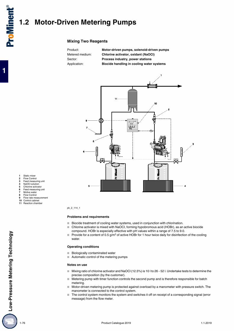
1.2 Motor-Driven Metering PumpsLo
w-Pr
essu
re M
eter
ing Te
chno
logy
1
Mixing Two Reagents
pk_2_114_1
Problems and requirements Biocide treatment of cooling water systems, used in conjunction with chlorination. Chlorine activator is mixed with NaOCI, forming hypobromous acid (HOBr), as an active biocide
compound. HOBr is especially effective with pH values within a range of 7.5 to 9.0. Provide for a content of 0.5 g/m3 of active HOBr for 1 hour twice daily for disinfection of the cooling
water.
Operating conditions Biologically contaminated water Automatic control of the metering pumps
Notes on use Mixing ratio of chlorine activator and NaOCl (12.5%) is 10 l to 26 - 52 l. Undertake tests to determine the
precise composition (by the customer). Metering pump with timer function controls the second pump and is therefore responsible for batch
metering. Motor-driven metering pump is protected against overload by a manometer with pressure switch. The
manometer is connected to the control system. The control system monitors the system and switches it off on receipt of a corresponding signal (error
message) from the flow meter.
Product: Motor-driven pumps, solenoid-driven pumpsMetered medium: Chlorine activator, oxidant (NaOCl)Sector: Process industry, power stationsApplication: Biocide handling in cooling water systems
1 Static mixer2 Flow Control3 Feed measuring unit4 NaOCl solution5 Chlorine activator6 Feed measuring unit7 Motive water8 Flow Control9 Flow rate measurement10 Control cabinet11 Reaction chamber
1-76 Product Catalogue 2019 1.1.2019

Low-
Pres
sure
Met
ering
Tech
nolog
y
1.2 Motor-Driven Metering Pumps
1
Solution Metering pump type gamma/ L with timer function (possibly external time switch) Metering pump Sigma X - S1Cb Metering monitor Flow Control Metering equipment Manometer with pressure switch
Benefits Good disinfection in alkaline water and water containing ammonia Cost-effective raw material base, which is also stable and non-corrosive Excellent safety due to flow control Simple and effective set-up for optimising the chemical composition through metering equipment.
1.1.2019 Product Catalogue 2019 1-77

1.2 Motor-Driven Metering PumpsLo
w-Pr
essu
re M
eter
ing Te
chno
logy
1
Safe and Reliable Chemical Metering with Reduced Pulsation
pk_2_117
Tasks and requirements For process-technical reasons, a low-pulsation metering flow is desired. Mass accelerating forces during metering, caused by the oscillating movement of the displacement
body in connection with the piping geometry need to be reduced. Cavitation-free process flow
Operating conditions/environment Long suction/discharge lines Line cross-section with small dimensions Metering of high-viscosity, inert media
Notes on application Pressure surges increase with increasing metering line length and smaller diameter; these may result
in impermissible pressure peaks. For longer pipes, as well as for higher viscosity media, the need for a PD using a pipe calculation
programme is to be evaluated. In an oscillating motor-driven metering pump, the maximum flow rate is approx. 3 times greater than the
mean, in a solenoid-driven pump approx. 5 times as great. This is to be considered when designing pipings without PD.
PD should be preloaded with compressed air or nitrogen at approx. 60-80% of the operating pressure to be expected.
Solution ProMinent® metering pumps Pressure-relief/overflow valves Pulsation dampers
Benefits Safe installation preventing damage to pumps and pipes Precise metering by avoiding of cavitation Compensation of delivery flow fluctuations
Product: Metering pump, accessoriesMetered medium: High viscosity chemicalsApplication: Use of pulsation damper (PD)
1-78 Product Catalogue 2019 1.1.2019

Low-
Pres
sure
Met
ering
Tech
nolog
y
1.3 Peristaltic Pumps DULCO®flex
1
1.3Peristaltic Pumps DULCO®flex
The virtually universal pump for many applications.Capacity range up to 15,000 l/h, up to 15 bar
The peristaltic pumps of product range DULCO®flex are ideal for almost all metering and pumping tasks in laboratories and industry. The reason: their extensive pump capacity range and the large number of different hose materials.This is how they work: The feed chemical is pumped by the rotor clamping the hose in the direction of flow. No valves are needed. Abrasive, viscous and gaseous media can thereby be gently conveyed.The pumping process is triggered by an elastomer hose, pressed by two rotating rollers or shoes against the pump housing. Once the rollers or shoes have passed by, the hose immediately returns to its original shape and creates a vacuum at the pump inlet. Atmospheric pressure causes the medium to flow in. The feed rate is proportional to the pump speed. A vacuum device can optionally be used to assist the hose to return to its position on product range DFCa and DFDa pumps, improving their suction behaviour and ensuring the even feed of viscose media.Whereas the pumps are fitted with roller technology for low pressures of up to 8 bar, they have shoes for higher pressures of up to 15 bar. Your benefits Simple to operate Reversible pumping direction Hose materials suitable for various chemicals Simple and quick hose change Safeguarded against running dry Self-priming Ideal for pumping pasty, viscous, abrasive and gaseous media
Field of applicationChemical industry, clarification plants, mining
P_DX_0028_SW3
DULCO®flex peristaltic pumps can be used to convey media with the following properties: pasty and solid-containing viscous abrasive shear-sensitive outgassing corrosiveThe pumps can be selected with the aid of an identity code:
Overview:
1.3.1 Peristaltic Pumps DULCO®flex
ProMinent® peristaltic pumps operate on a simple functional principle and stand out thanks to their compact and robust design. They are self-priming and operate without seals and valves.
P_DX_0010_SW1
Type Application Feed rateat max. pressure
Max. pressure Rollers/shoes
l/h barDFBa Industry 650 8 RollersDFCa Industry 8,900 8 RollersDFDa Industry 15,000 15 Shoes
1.1.2019 Product Catalogue 2019 1-79
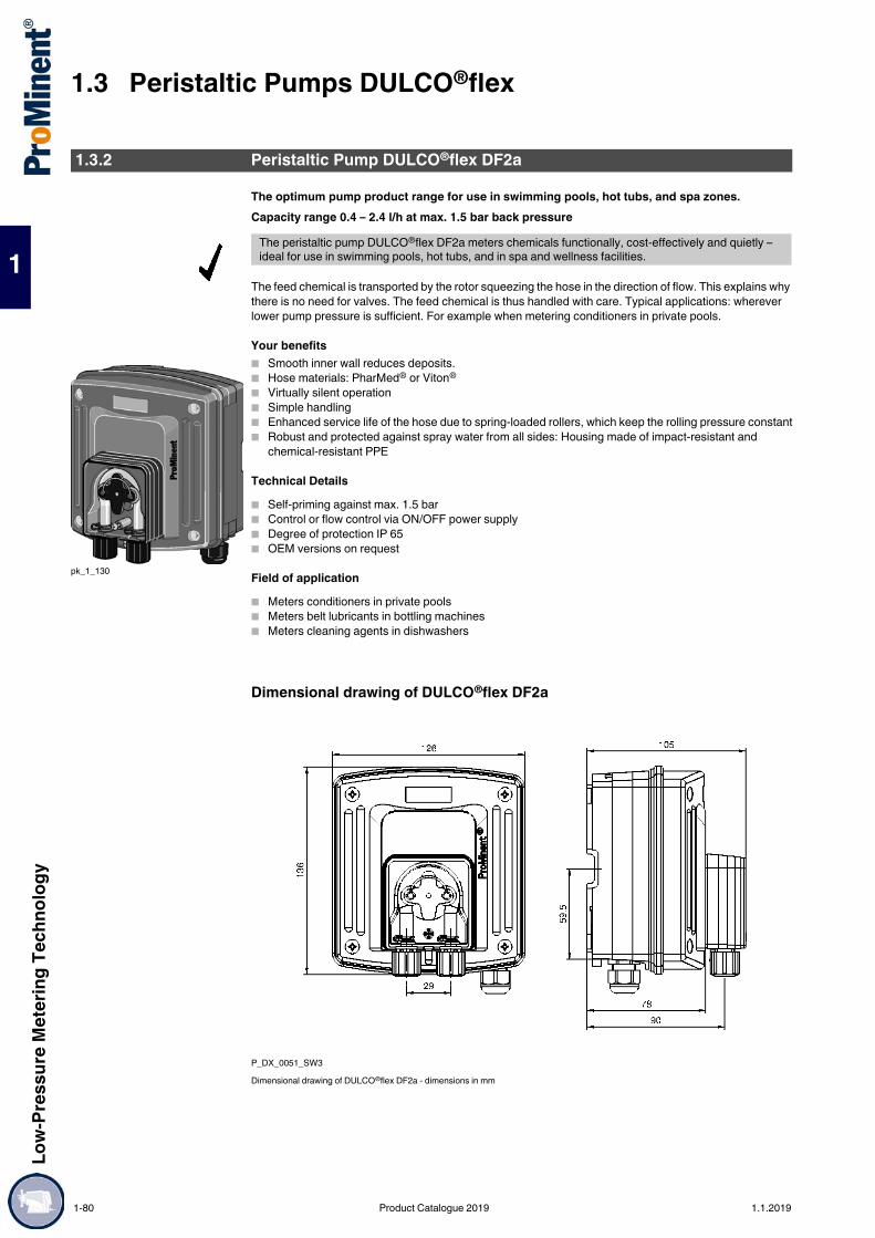
1.3 Peristaltic Pumps DULCO®flexLo
w-Pr
essu
re M
eter
ing Te
chno
logy
1
The optimum pump product range for use in swimming pools, hot tubs, and spa zones.Capacity range 0.4 – 2.4 l/h at max. 1.5 bar back pressure
The feed chemical is transported by the rotor squeezing the hose in the direction of flow. This explains why there is no need for valves. The feed chemical is thus handled with care. Typical applications: wherever lower pump pressure is sufficient. For example when metering conditioners in private pools.
Your benefits Smooth inner wall reduces deposits. Hose materials: PharMed® or Viton®
Virtually silent operation Simple handling Enhanced service life of the hose due to spring-loaded rollers, which keep the rolling pressure constant Robust and protected against spray water from all sides: Housing made of impact-resistant and
chemical-resistant PPE
Technical Details Self-priming against max. 1.5 bar Control or flow control via ON/OFF power supply Degree of protection IP 65 OEM versions on request
Field of application Meters conditioners in private pools Meters belt lubricants in bottling machines Meters cleaning agents in dishwashers
Dimensional drawing of DULCO®flex DF2a
P_DX_0051_SW3Dimensional drawing of DULCO®flex DF2a - dimensions in mm
1.3.2 Peristaltic Pump DULCO®flex DF2a
The peristaltic pump DULCO®flex DF2a meters chemicals functionally, cost-effectively and quietly – ideal for use in swimming pools, hot tubs, and in spa and wellness facilities.
pk_1_130
1-80 Product Catalogue 2019 1.1.2019

Low-
Pres
sure
Met
ering
Tech
nolog
y
1.3 Peristaltic Pumps DULCO®flex
1
Identity Code Ordering System for Product Range DULCO®flex, Version DF2a
Viton® and PharMed® are registered trademarks.
Technical Data
All data refers to water at 20 °C.
Spare Hoses
DF2a Type Capacitybar l/h
0204 1.5 0.40208 1.5 0.80216 1.5 1.60224 1.5 2.4
Hose materialP PharMed®
V Viton® for fragrances (special version)Version0 With ProMinent® logo1 Without ProMinent® logo
Hydraulic connectors0 Connector for hose 6/4 mm suction and discharge side9 Connector for hose 10/4 mm discharge side only
Power supplyA 230 V ± 10%, 50/60 Hz
Cable and plug0 No mains lead1 With 2 m mains lead, open endedA With mains cable, European plug
Drive0 Mains ON/OFF
InstallationW Wall mounted
Accessories0 No accessories
Type Capacity Frequency Connector size
Suction lift Intake head
bar l/h rpm o Ø x i Ø m WC m WC0204 1.5 0.4 5 6x4/10x4 4 30208 1.5 0.8 10 6x4/10x4 4 30216 1.5 1.6 20 6x4/10x4 4 30224 1.5 2.4 30 6x4/10x4 4 3
Admissible ambient temperature: 10-45 °CPower consumption approx.: 5 WSwitching duration: 100%Enclosure rating: IP 65
Order no.Spare hose set, complete, PharMed® 1009480Replacement hose compl. Viton® 1023842
1.1.2019 Product Catalogue 2019 1-81

1.3 Peristaltic Pumps DULCO®flexLo
w-Pr
essu
re M
eter
ing Te
chno
logy
1
The optimum pump for use in swimming pools, hot tubs and spa and wellness facilities.Capacity range 1.5 – 12 l/h, 4 – 2 bar
There are three designs of DULCO®flex DF4a available. 1 Metering chemicals2 Metering activated charcoal3 Metering flocculantsThis guarantees that the operating menu, inputs and outputs are always adapted to the respective application.
Your benefits Language-neutral user navigation Continuous adjustment of capacity Hose material in PharMed®
Full control, as the capacity is shown in l/h in the display Safe and reliable operation: Flow volume and concentration can be entered reproducibly Long service life: Spring-loaded rollers stabilise rolling pressure and reduce wear and tear on the hose No irritating noise: low-noise stepper motor with ball bearing drive shaft Fast to use: simple installation and retrofitting, even with existing systems Guaranteed safety: Hose rupture monitoring system and fault indicating relay register and report all
problems. Suitable for use around the clock – 100% switch-on time Operating hours counter for the peristaltic pump - always stay informed.
Technical Details Priming function Night setback Inputs for contacts and analogue signals Housing degree of protection IP 65 Connector for 2-stage level switch with round plug Operating hour counter CANopen interface
Field of applicationSwimming pool water treatment
Dimensional drawing of DULCO®flex DF4a
DF4a_SW3Dimensional drawing of DULCO®flex DF4a - dimensions in mm
1.3.3 Peristaltic Pump DULCO®flex DF4a
The peristaltic pump DULCO®flex DF4a for metering flocculants and activated charcoal treats water precisely and accurately. It is ideal for use in swimming pools, hot tubs or spa and wellness facilities. An operating pressure up to 4 bar is possible.
P_DX_0006_SW1
1-82 Product Catalogue 2019 1.1.2019

Low-
Pres
sure
Met
ering
Tech
nolog
y
1.3 Peristaltic Pumps DULCO®flex
1
Identity Code Ordering System for Product Range DULCO®flex, Version DF4a
PharMed® is a registered trademark.
Technical Data
All data refers to water at 20 °C.
Spare Hoses
DF4a Application0 Chemical pumpA Activated charcoal meteringF Flocculant metering
InstallationW Wall mounting
Version0 With ProMinent® logo1 Without ProMinent® logo
Type Capacitybar l/h
04004 4.0 0.3504015 3.0 1.5003060 2.0 6.0002120 1.5 12.00
Hose materialP PharMed®
Hydraulic connectors0 Standard connector 6x49 Special connector 10x4 discharge side
Power supplyU 100 - 240 VAC, 50/60 Hz
Cable and plug0 Without cable1 With cable 2.0 m; open endA With cable 2.0 m; Euro connectorB With cable 2.0 m; Swiss connector
Accessories0 Without accessories2 With lip-seal metering valve PCB and 10 m PE metering line
Hardware extension0 None
Language default00 Language-neutral
Relay1 Fault signalling relay, drop-out action3 Fault signalling relay, pick-up action
Control versions8 manual + external contact and analogue
0/4 - 20 mA + 0 - 10 VC as "8" and CANopenD such as "8" and CANopen and CAN connector
Further input1 Pause + 2-stage level + AUX12 Pause + 1-stage level + AUX1 + AUX2
Pause/level0 Pause break contact + level break contact
Approvals01 CE-Symbol
Priming lift 3 m WC Approx. power consumption: 24 WSuction lift 4 m WC Switching duration: 100%Speed 0 - 85 RPM Degree of protection: IP 65Permissible ambient temperature: 10-45 °C
Order no.For type 04004 PharMed® 1034997For type 04015 PharMed® 1030722For type 03060 PharMed® 1030723For type 02120 PharMed® 1030774
1.1.2019 Product Catalogue 2019 1-83

1.3 Peristaltic Pumps DULCO®flexLo
w-Pr
essu
re M
eter
ing Te
chno
logy
1
Low and medium pump capacitiesFeed rates of up to 649 l/h at 8 bar
The peristaltic pump DULCO®flex DFBa is equipped with rollers and fabric-reinforced hoses for tough industrial use. Pumps with a Halar-coated pump housing can be produced for use in the chemical industry.
Your benefits Simple to operate Reversible pumping direction Hose materials suitable for various chemicals Simple and quick hose change Ideal for pumping pasty, high-viscosity, abrasive and gaseous media Self-priming Safeguarded against running dry
Technical Details Connector sizes 3/8 - 1" Feed rates of 0.023 - 0.24 l/rev Hose materials NR, NBR, EPDM, NR-A, Norprene, NBR-A, Hypalon, Tygon Self-priming up to 8 m Back pressure up to 8 barOptions Stainless steel base plate Available as a mobile unit Various connectors, such as BSP, NPT, Tri-Clamp and DIN 11851 Pulsation damper Leakage sensor Housing with Halar coating Food approval EU 1935/2004
Field of application Chemical industry Waste water Mining
Technical Data
1.3.4 Peristaltic Pump DULCO®flex DFBa
The peristaltic pump DULCO®flex DFBa is designed for low and medium pump capacities of up to 649 l/h at 8 bar.
Hose NR, NBR, EPDM, NR-A, Norprene, NBR-A, Hypalon, TygonSelf-priming up to 8 mRollers / shoes Rollers
Type Feed rate /revolution
Delivery rate at max.back pressure
Hose diameter(internal)
Max.solids
Weightwithout drive
Connection DN
l/rev. bar l/h mm mm kgDFBa 010 0.02 8 60 10 2.5 6 3/8"DFBa 013 0.04 8 100 13 3.3 6 3/8"DFBa 016 0.09 8 188 16 4.0 13 3/4"DFBa 019 0.12 2 671 19 4.8 13 1"DFBa 022 0.24 8 649 22 5.5 22 1"
1-84 Product Catalogue 2019 1.1.2019

Low-
Pres
sure
Met
ering
Tech
nolog
y
1.3 Peristaltic Pumps DULCO®flex
1
Identity Code Ordering System for Peristaltic Pump DULCO®flex DFBa 010
* The pumps are factory-set to a maximum back pressure of 4 bar, unless the stated pressure is lower. Please state any deviating pressures when ordering.
DFBa Type010 DFBa 010, 0.023 l/revolution
Power end/drive*000 without drive unitA10 0.12 kW, 15 rpm, 21 l/h, 8 bar (Reduction gear system), 3-phase, 230/400 V ACA11 0.12 kW, 20 rpm, 28 l/h, 8 bar (Reduction gear system), 3-phase, 230/400 V ACA12 0.18 kW, 29 rpm, 40 l/h, 6 bar (Reduction gear system), 3-phase, 230/400 V ACA13 0.18 kW, 46 rpm, 64 l/h, 4 bar (Reduction gear system), 3-phase, 230/400 V ACA14 0.25 kW, 57 rpm, 79 l/h, 4 bar (Reduction gear system), 3-phase, 230/400 V ACA15 0.25 kW, 70 rpm, 97 l/h, 2 bar (Reduction gear system), 3-phase, 230/400 V ACA21 0.12 kW, 3 - 16 rpm, 4-22 l/h, 8 bar (Manual adjustment gear), 3-phase, 230/400 V ACA22 0.25 kW, 5 – 29 rpm, 7 – 40 l/h, 6 bar (Manual adjustment gear), 3-phase, 230/400 V ACA23 0.25 kW, 10 - 53 rpm, 14-73 l/h, 4 bar (Manual adjustment gear), 3-phase, 230/400 V ACA24 0.25 kW, 15 - 80 rpm, 21-110 l/h, 2 bar (Manual adjustment gear), 3-phase, 230/400 V ACA31 0.37 kW, 9 - 34 rpm, 12 – 47 l/h, 20 – 75 Hz, 6 bar (Gear motor with integrated frequency converter), 1-phase, 230 V ACA32 0.37 kW, 16 - 60 rpm, 22-83 l/h, 20-75 Hz, 4 bar (Gear motor with integrated frequency converter), 1-phase, 230 V ACA41 0.18 kW, 1 - 34 rpm, 1 – 47 l/h, 3 – 75 Hz, 6 bar (Gear motor, external frequency converter required), 3-phase, 230/400 V ACA42 0.18 kW, 2 - 44 rpm, 3 – 60 l/h, 3 – 75 Hz, 4 bar (Gear motor, external frequency converter required), 3-phase, 230/400 V ACA43 0.25 kW, 3-69 rpm, 4-95 l/h, 3-75 Hz, 4 bar (Gear motor, external frequency converter required), 3-phase, 230/400 V AC
Hose material0 NRB NBRE EPDMR NR-A (lebensmittelecht)N Norprene (max. 2 bar) (lebensmittelecht)A NBR-A (lebensmittelecht)H Hypalon
Hydraulic connectionsA VA BSP 3/8"B VA NPT 3/8"C PP BSP 3/8"D PVDF BSP 3/8"E PVDF NPT 3/8"F PVC NPT 3/8"G Tri-Clamp, VA, 1/2"H DIN 11851, VA, NW10
Base plate0 Base plate, painted steel1 Base plate, stainless steel2 Portable unit + painted steel base plate3 Portable unit + stainless steel base plate
Leakage sensor0 Without leakage sensorL With leakage sensorM as "L" + relay output
Rotor0 Rotor with 2 rollers
Batch controller0 Without controller
Special version0 StandardH Halar-coated housing
Vacuum system0 without
Approvals01 CE02 CE+Food approval EU 1935/2004
1.1.2019 Product Catalogue 2019 1-85

1.3 Peristaltic Pumps DULCO®flexLo
w-Pr
essu
re M
eter
ing Te
chno
logy
1
Identity Code Ordering System for Peristaltic Pump DULCO®flex DFBa 013
* The pumps are factory-set to a maximum back pressure of 4 bar, unless the stated pressure is lower. Please state any deviating pressures when ordering.
DFBa Type013 DFBa 013, 0.039 l/revolution
Power end/drive*000 without drive unitB10 0.12 kW, 15 rpm, 35 l/h, 8 bar (Reduction gear system), 3-phase, 230/400 V ACB11 0.12 kW, 20 rpm, 46 l/h, 8 bar (Reduction gear system), 3-phase, 230/400 V ACB12 0.18 kW, 29 rpm, 67 l/h, 6 bar (Reduction gear system), 3-phase, 230/400 V ACB13 0.18 kW, 46 rpm, 107 l/h, 4 bar (Reduction gear system), 3-phase, 230/400 V ACB14 0.25 kW, 57 rpm, 133 l/h, 4 bar (Reduction gear system), 3-phase, 230/400 V ACB15 0.25 kW, 70 rpm, 163 l/h, 2 bar (Reduction gear system), 3-phase, 230/400 V ACB21 0.12 kW, 3 - 16 rpm, 7-37 l/h, 8 bar (Manual adjustment gear), 3-phase, 230/400 V ACB22 0.25 kW, 5 – 29 rpm, 11 – 67 l/h, 6 bar (Manual adjustment gear), 3-phase, 230/400 V ACB23 0.25 kW, 10 - 53 rpm, 23-124 l/h, 4 bar (Manual adjustment gear), 3-phase, 230/400 V ACB24 0.25 kW, 15 - 80 rpm, 35-187 l/h, 2 bar (Manual adjustment gear), 3-phase, 230/400 V ACB31 0.37 kW, 9 - 34 rpm, 21 – 79 l/h, 20 – 75 Hz, 6 bar (Gear motor with integrated frequency converter), 1-phase, 230 V ACB32 0.37 kW, 16 - 60 rpm, 37-140 l/h, 20-75 Hz, 4 bar (Gear motor with integrated frequency converter), 1-phase, 230 V ACB41 0.18 kW, 1 - 34 rpm, 2 – 78 l/h, 3 – 75 Hz, 6 bar (Gear motor, external frequency converter required), 3-phase, 230/400 V ACB42 0.18 kW, 2 - 44 rpm, 5 – 100 l/h, 3 – 75 Hz, 4 bar (Gear motor, external frequency converter required), 3-phase, 230/400 V ACB43 0.25 kW, 3-69 rpm, 7-157 l/h, 3-75 Hz, 4 bar (Gear motor, external frequency converter required), 3-phase, 230/400 V AC
Hose material0 NRB NBRE EPDMR NR-AN Norprene (max. 2 bar)A NBR-AH Hypalon
Hydraulic connectionsA VA BSP 3/8"B VA NPT 3/8"C PP BSP 3/8"D PVDF BSP 3/8"E PVDF NPT 3/8"F PVC NPT 3/8"G Tri-Clamp, VA, 3/4"H DIN 11851, VA, NW15
Base plate0 Base plate, painted steel1 Base plate, stainless steel2 Portable unit + painted steel base plate3 Portable unit + stainless steel base plate
Leakage sensor0 Without leakage sensorL With leakage sensorM as "L" + relay output
Rotor0 Rotor with 2 rollers
Batch controller0 Without controller
Special version0 StandardH Halar-coated housing
Vacuum system0 without
Approvals01 CE02 CE+Food approval EU 1935/2004
1-86 Product Catalogue 2019 1.1.2019

Low-
Pres
sure
Met
ering
Tech
nolog
y
1.3 Peristaltic Pumps DULCO®flex
1
Identity Code Ordering System for Peristaltic Pump DULCO®flex DFBa 016
* The pumps are factory-set to a maximum back pressure of 4 bar, unless the stated pressure is lower. Please state any deviating pressures when ordering.
DFBa Type016 DFBa 016, 0.092 l/revolution
Power end/drive*000 without drive unitC10 0.18 kW, 14 rpm, 77 l/h, 8 bar (Reduction gear system), 3-phase, 230/400 V ACC11 0.18 kW, 20 rpm, 110 l/h, 8 bar (Reduction gear system), 3-phase, 230/400 V ACC12 0.25 kW, 32 rpm, 176 l/h, 4 bar (Reduction gear system), 3-phase, 230/400 V ACC13 0.25 kW, 46 rpm, 253 l/h, 4 bar (Reduction gear system), 3-phase, 230/400 V ACC14 0.37 kW, 57 rpm, 314 l/h, 4 bar (Reduction gear system), 3-phase, 230/400 V ACC15 0.37 kW, 70 rpm, 386 l/h, 2 bar (Reduction gear system), 3-phase, 230/400 V ACC21 0.37 kW, 8 - 50 rpm, 44-276 l/h, 4 bar (Manual adjustment gear), 3-phase, 230/400 V ACC22 0.37 kW, 10 - 61 rpm, 55-336 l/h, 2 bar (Manual adjustment gear), 3-phase, 230/400 V ACC23 0.37 kW, 16 - 91 rpm, 88-502 l/h, 1 bar (Manual adjustment gear), 3-phase, 230/400 V ACC31 0.37 kW, 9 - 34 rpm, 49 – 187 l/h, 20 – 75 Hz, 4 bar (Gear motor with integrated frequency converter), 1-phase, 230 V ACC32 0.37 kW, 16 - 60 rpm, 88-331 l/h, 20-75 Hz, 2 bar (Gear motor with integrated frequency converter), 1-phase, 230 V ACC41 0.25 kW, 1 – 34 rpm, 5 – 188 l/h, 3 – 75 Hz, 4 bar (Gear motor, external frequency converter required), 3-phase, 230/400 V ACC42 0.25 kW, 2-48 rpm, 11-265 l/h, 3-75 Hz, 4 bar (Gear motor, external frequency converter required), 3-phase, 230/400 V ACC43 0.37 kW, 3-69 rpm, 16-381 l/h, 3-75 Hz, 2 bar (Gear motor, external frequency converter required), 3-phase, 230/400 V AC
Hose material0 NRB NBRE EPDMR NR-AN Norprene (max. 2 bar)A NBR-AH Hypalon
Hydraulic connectionsA VA BSP 3/4"B VA NPT 3/4"C PP BSP 3/4"D PVDF BSP 3/4"E PVDF NPT 3/4"F PVC NPT 3/4"G Tri-Clamp, VA, 1"H DIN 11851, VA, NW20
Base plate0 Base plate, painted steel1 Base plate, stainless steel2 Portable unit + painted steel base plate3 Portable unit + stainless steel base plate
Leakage sensor0 Without leakage sensorL With leakage sensorM as "L" + relay output
Rotor0 Rotor with 2 rollers
Batch controller0 Without controller
Special version0 StandardH Halar-coated housing
Vacuum system0 without
Approvals01 CE02 CE+Food approval EU 1935/2004
1.1.2019 Product Catalogue 2019 1-87
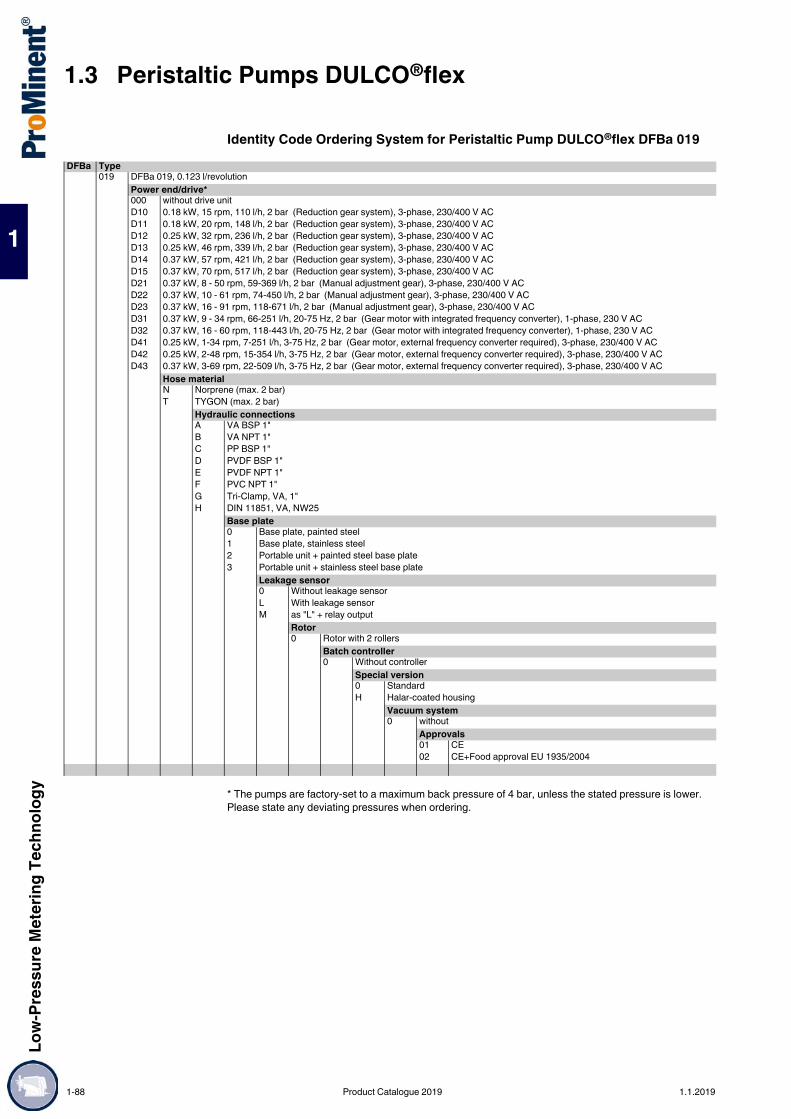
1.3 Peristaltic Pumps DULCO®flexLo
w-Pr
essu
re M
eter
ing Te
chno
logy
1
Identity Code Ordering System for Peristaltic Pump DULCO®flex DFBa 019
* The pumps are factory-set to a maximum back pressure of 4 bar, unless the stated pressure is lower. Please state any deviating pressures when ordering.
DFBa Type019 DFBa 019, 0.123 l/revolution
Power end/drive*000 without drive unitD10 0.18 kW, 15 rpm, 110 l/h, 2 bar (Reduction gear system), 3-phase, 230/400 V ACD11 0.18 kW, 20 rpm, 148 l/h, 2 bar (Reduction gear system), 3-phase, 230/400 V ACD12 0.25 kW, 32 rpm, 236 l/h, 2 bar (Reduction gear system), 3-phase, 230/400 V ACD13 0.25 kW, 46 rpm, 339 l/h, 2 bar (Reduction gear system), 3-phase, 230/400 V ACD14 0.37 kW, 57 rpm, 421 l/h, 2 bar (Reduction gear system), 3-phase, 230/400 V ACD15 0.37 kW, 70 rpm, 517 l/h, 2 bar (Reduction gear system), 3-phase, 230/400 V ACD21 0.37 kW, 8 - 50 rpm, 59-369 l/h, 2 bar (Manual adjustment gear), 3-phase, 230/400 V ACD22 0.37 kW, 10 - 61 rpm, 74-450 l/h, 2 bar (Manual adjustment gear), 3-phase, 230/400 V ACD23 0.37 kW, 16 - 91 rpm, 118-671 l/h, 2 bar (Manual adjustment gear), 3-phase, 230/400 V ACD31 0.37 kW, 9 - 34 rpm, 66-251 l/h, 20-75 Hz, 2 bar (Gear motor with integrated frequency converter), 1-phase, 230 V ACD32 0.37 kW, 16 - 60 rpm, 118-443 l/h, 20-75 Hz, 2 bar (Gear motor with integrated frequency converter), 1-phase, 230 V ACD41 0.25 kW, 1-34 rpm, 7-251 l/h, 3-75 Hz, 2 bar (Gear motor, external frequency converter required), 3-phase, 230/400 V ACD42 0.25 kW, 2-48 rpm, 15-354 l/h, 3-75 Hz, 2 bar (Gear motor, external frequency converter required), 3-phase, 230/400 V ACD43 0.37 kW, 3-69 rpm, 22-509 l/h, 3-75 Hz, 2 bar (Gear motor, external frequency converter required), 3-phase, 230/400 V AC
Hose materialN Norprene (max. 2 bar)T TYGON (max. 2 bar)
Hydraulic connectionsA VA BSP 1"B VA NPT 1"C PP BSP 1"D PVDF BSP 1"E PVDF NPT 1"F PVC NPT 1"G Tri-Clamp, VA, 1"H DIN 11851, VA, NW25
Base plate0 Base plate, painted steel1 Base plate, stainless steel2 Portable unit + painted steel base plate3 Portable unit + stainless steel base plate
Leakage sensor0 Without leakage sensorL With leakage sensorM as "L" + relay output
Rotor0 Rotor with 2 rollers
Batch controller0 Without controller
Special version0 StandardH Halar-coated housing
Vacuum system0 without
Approvals01 CE02 CE+Food approval EU 1935/2004
1-88 Product Catalogue 2019 1.1.2019

Low-
Pres
sure
Met
ering
Tech
nolog
y
1.3 Peristaltic Pumps DULCO®flex
1
Identity Code Ordering System for Peristaltic Pump DULCO®flex DFBa 022
* The pumps are factory-set to a maximum back pressure of 4 bar, unless the stated pressure is lower. Please state any deviating pressures when ordering.
DFBa Type022 DFBa 022, 0.246 l/revolution
Power end/drive*000 without drive unitE10 0.25 kW, 17 rpm, 251 l/h, 8 bar (Reduction gear system), 3-phase, 230/400 V ACE11 0.37 kW, 23 rpm, 339 l/h, 8 bar (Reduction gear system), 3-phase, 230/400 V ACE12 0.55 kW, 38 rpm, 561 l/h, 4 bar (Reduction gear system), 3-phase, 230/400 V ACE13 0.55 kW, 45 rpm, 664 l/h, 4 bar (Reduction gear system), 3-phase, 230/400 V ACE14 0.55 kW, 54 rpm, 797 l/h, 2 bar (Reduction gear system), 3-phase, 230/400 V ACE15 0.75 kW, 66 rpm, 974 l/h, 2 bar (Reduction gear system), 3-phase, 230/400 V ACE21 0.37 kW, 4-20 rpm, 59-295 l/h, 8 bar (Manual adjustment gear), 3-phase, 230/400 V ACE22 0.55 kW, 6 - 32 rpm, 89-472 l/h, 4 bar (Manual adjustment gear), 3-phase, 230/400 V ACE23 0.75 kW, 9 - 48 rpm, 133-708 l/h, 2 bar (Manual adjustment gear), 3-phase, 230/400 V ACE31 0.55 kW, 12 - 44 rpm, 177-649 l/h, 20-75 Hz, 4 bar (Gear motor with integrated frequency converter), 3-phase, 400 V ACE32 0.75 kW, 18 - 67 rpm, 266-989 l/h, 20-75 Hz, 2 bar (Gear motor with integrated frequency converter), 3-phase, 400 V ACE41 0.55 kW, 2 - 44 rpm, 30 – 649 l/h, 3 – 75 Hz, 4 bar (Gear motor, external frequency converter required), 3-phase, 230/400 V ACE42 0.75 kW, 2-57 rpm, 30-841 l/h, 3-75 Hz, 4 bar (Gear motor, external frequency converter required), 3-phase, 230/400 V ACE43 1.1 kW, 3 - 81 rpm, 44-1196 l/h, 3-75 Hz, 2 bar (Gear motor, external frequency converter required), 3-phase, 230/400 V AC
Hose material0 NR (natural rubber)B NBRE EPDMR NR-AN Norprene (max. 2 bar back pressure)A NBR-AH Hypalon
Hydraulic connectionsA VA BSP 1"B VA NPT 1"C PP BSP 1"D PVDF BSP 1"E PVDF NPT 1"F PVC NPT 1"G Tri-Clamp, VA, 1"H DIN 11851, VA, NW25
Base plate0 Base plate, painted steel1 Base plate, stainless steel2 Portable unit + painted steel base plate3 Portable unit + stainless steel base plate
Leakage sensor0 Without leakage sensorL With leakage sensorM as "L" + relay output
Rotor0 Rotor with 2 rollers
Batch controller0 Without controller
Special version0 StandardH Halar-coated housing
Vacuum system0 without
Approvals01 CE02 CE+Food approval EU 1935/2004
1.1.2019 Product Catalogue 2019 1-89

1.3 Peristaltic Pumps DULCO®flexLo
w-Pr
essu
re M
eter
ing Te
chno
logy
1
High pump capacities and long service lifeFeed rates of up to 8,900 l/h at 8 bar
It is ideal for heavy-duty industrial applications and pump capacities of up to 8,900 l/h at 8 bar back pressure.A ball-bearing mounted rotor ensures extremely smooth running and a long service life.Pumps with a Halar-coated pump housing can be produced for use in the chemical industry.A vacuum unit can optionally be used to help the hose to return to its original shape with pumps of the product range DFCa, thereby improving their suction behaviour and ensuring the even feed of high-viscosity media.
Your benefits Simple to operate Reversible pumping direction Hose materials suitable for various chemicals Simple and quick hose change Ideal for pumping pasty, high-viscosity, abrasive and gaseous media Self-priming Safeguarded against running dry
Technical Details Connector sizes 1 1/4″- DN 80 Feed rates of 0.43 - 6.72 l/rev Hose materials NR, NBR, EPDM, Norprene, NR-A, NBR-A Self-priming up to 8 m Back pressure up to 8 barOptions Stainless steel base plate Available as a mobile unit Various connectors, such as BSP, NPT, Tri-Clamp, DIN 11851 and flange Pulsation damper Leakage sensor Housing with Halar coating Vacuum system Food approval EU 1935/2004
Field of application Chemical industry Waste water Mining
Technical Data
1.3.5 Peristaltic Pump DULCO®flex DFCa
High pump capacities are not a problem with the peristaltic pump DULCO®flex DFCa. It is equipped with extra rollers and fabric-reinforced hoses for industrial use.
Hose NR, NBR, EPDM, NR-A, Norprene, NBR-ASelf-priming up to 8 mRollers / shoes Rollers
Type Feed rate /revolution
Delivery rate at max.back pressure
Hose diameter (internal)
Max. solids Weightwithout drive
Connection DN
l/rev. bar l/h mm kgDFCa 030 0.43 8 727 28 7.0 62 DN 32DFCa 040 0.86 8 1,495 35 8.8 89 DN 40DFCa 050 1.47 8 1,852 40 10.0 140 DN 40DFCa 060 3.16 8 5,100 55 13.8 235 DN 50DFCa 070 6.72 8 8,900 65 16.3 440 DN 65
1-90 Product Catalogue 2019 1.1.2019

Low-
Pres
sure
Met
ering
Tech
nolog
y
1.3 Peristaltic Pumps DULCO®flex
1
Identity Code Ordering System for Peristaltic Pump DULCO®flex DFCa 030
* The pumps are factory-set to a maximum back pressure of 4 bar, unless the stated pressure is lower. Please state any deviating pressures when ordering.
DFCa Type030 DFCa 030, 0.433 l/revolution
Power end/drive*000 without drive unitA11 0.25 kW, 18 rpm, 468 l/h, 4 bar (Reduction gear system), 3-phase, 230/400 V ACA12 0.37 kW, 29 rpm, 753 l/h, 4 bar (Reduction gear system), 3-phase, 230/400 V ACA13 0.55 kW, 38 rpm, 987 l/h, 4 bar (Reduction gear system), 3-phase, 230/400 V ACA14 0.55 kW, 55 rpm, 1429 l/h, 2 bar (Reduction gear system), 3-phase, 230/400 V ACA31 0.55 kW, 11 - 39 rpm, 286-1,013 l/h, 20-75 Hz, 4 bar (Gear motor with integrated frequency converter), 3-phase, 400 V ACA32 0.75 kW, 18 - 63 rpm, 468 - 1,637 l/h, 20-75 Hz, 2 bar (Gear motor with integrated frequency converter), 3-phase, 400 V ACA41 0.37 kW, 2 - 28 rpm, 52 – 727 l/h, 3 – 50 Hz, 4 bar (Gear motor, external frequency converter required), 3-phase, 230/400 V ACA42 0.75 kW, 3 - 59 rpm, 78-1,533 l/h, 3-65 Hz, 2 bar (Gear motor, external frequency converter required), 3-phase, 230/400 V AC
Hose material0 NRB NBRE EPDMR NR-AA NBR-AN Norprene (max. 2 bar)
Hydraulic connectionsA VA BSP 1 1/4"B VA NPT 1 1/4"C PP BSP 1 1/4"D PVDF/PTFE BSP 1 1/4"F PVC NPT 1 1/4"G Tri-Clamp, VA, 1 1/2"H DIN 11851, VA, NW32I DIN flange VA DN32L ANSI flange VA, 1 1/4"P ANSI flange PVC, 1 1/4"
Base plate0 Base plate, painted steel1 Base plate, stainless steel2 Portable unit + painted steel base plate3 Portable unit + stainless steel base plate
Leakage sensor0 without leakage sensorL with leakage sensorM as "L" + relay output
Rotor0 Rotor with 2 rollers
Batch controller0 without controller
Special version0 StandardH Halar-coated housing
Vacuum system0 withoutV with vacuum system
Approvals01 CE02 CE+Food approval EU 1935/2004
1.1.2019 Product Catalogue 2019 1-91
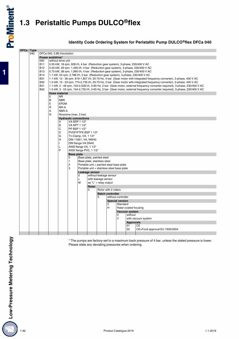
1.3 Peristaltic Pumps DULCO®flexLo
w-Pr
essu
re M
eter
ing Te
chno
logy
1
Identity Code Ordering System for Peristaltic Pump DULCO®flex DFCa 040
* The pumps are factory-set to a maximum back pressure of 4 bar, unless the stated pressure is lower. Please state any deviating pressures when ordering.
DFCa Type040 DFCa 040, 0.86 l/revolution
Power end/drive*000 without drive unitB11 0.55 kW, 18 rpm, 928 l/h, 4 bar (Reduction gear system), 3-phase, 230/400 V ACB12 0.55 kW, 29 rpm, 1,495 l/h, 4 bar (Reduction gear system), 3-phase, 230/400 V ACB13 0.75 kW, 38 rpm, 1,960 l/h, 4 bar (Reduction gear system), 3-phase, 230/400 V ACB14 1.1 kW, 54 rpm, 2,786 l/h, 2 bar (Reduction gear system), 3-phase, 230/400 V ACB31 1.1 kW, 12 - 36 rpm, 619-1,857 l/h, 20-70 Hz, 4 bar (Gear motor with integrated frequency converter), 3-phase, 400 V ACB32 1.5 kW, 15 - 53 rpm, 774-2,735 l/h, 20-70 Hz, 2 bar (Gear motor with integrated frequency converter), 3-phase, 400 V ACB41 1.1 kW, 2 - 49 rpm, 103-2,528 l/h, 3-65 Hz, 2 bar (Gear motor, external frequency converter required), 3-phase, 230/400 V ACB42 1.5 kW, 3 - 53 rpm, 154-2,735 l/h, 3-65 Hz, 2 bar (Gear motor, external frequency converter required), 3-phase, 230/400 V AC
Hose material0 NRB NBRE EPDMR NR-AA NBR-AN Norprene (max. 2 bar)
Hydraulic connectionsA VA BSP 1 1/2"B VA NPT 1 1/2"C PP BSP 1 1/2"D PVDF/PTFE BSP 1 1/2"G Tri-Clamp, VA, 1 1/2"H DIN 11851, VA, NW40I DIN flange VA DN40L ANSI flange VA, 1 1/2"P ANSI flange PVC, 1 1/2"
Base plate0 Base plate, painted steel1 Base plate, stainless steel2 Portable unit + painted steel base plate3 Portable unit + stainless steel base plate
Leakage sensor0 without leakage sensorL with leakage sensorM as "L" + relay output
Rotor0 Rotor with 2 rollers
Batch controller0 without controller
Special version0 StandardH Halar-coated housing
Vacuum system0 withoutV with vacuum system
Approvals01 CE02 CE+Food approval EU 1935/2004
1-92 Product Catalogue 2019 1.1.2019
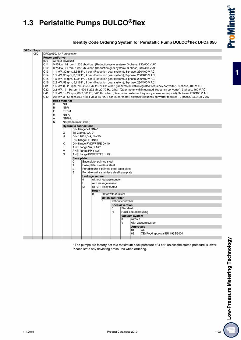
Low-
Pres
sure
Met
ering
Tech
nolog
y
1.3 Peristaltic Pumps DULCO®flex
1
Identity Code Ordering System for Peristaltic Pump DULCO®flex DFCa 050
* The pumps are factory-set to a maximum back pressure of 4 bar, unless the stated pressure is lower. Please state any deviating pressures when ordering.
DFCa Type050 DFCa 050, 1.47 l/revolution
Power end/drive*000 without drive unitC11 0.55 kW, 14 rpm, 1,235 l/h, 4 bar (Reduction gear system), 3-phase, 230/400 V ACC12 0.75 kW, 21 rpm, 1,852 l/h, 4 bar (Reduction gear system), 3-phase, 230/400 V ACC13 1.1 kW, 30 rpm, 2,646 l/h, 4 bar (Reduction gear system), 3-phase, 230/400 V ACC14 1.5 kW, 38 rpm, 3,352 l/h, 4 bar (Reduction gear system), 3-phase, 230/400 V ACC15 1.5 kW, 48 rpm, 4,234 l/h, 2 bar (Reduction gear system), 3-phase, 230/400 V ACC16 2.2 kW, 58 rpm, 5,116 l/h, 2 bar (Reduction gear system), 3-phase, 230/400 V ACC31 1.5 kW, 8 - 29 rpm, 706-2,558 l/h, 20-70 Hz, 4 bar (Gear motor with integrated frequency converter), 3-phase, 400 V ACC32 2.2 kW, 17 - 60 rpm, 1,499-5,292 l/h, 20-70 Hz, 2 bar (Gear motor with integrated frequency converter), 3-phase, 400 V ACC41 1.5 kW, 1 - 27 rpm, 88-2,381 l/h, 3-65 Hz, 4 bar (Gear motor, external frequency converter required), 3-phase, 230/400 V ACC42 2.2 kW, 3 - 55 rpm, 265-4,851 l/h, 3-65 Hz, 2 bar (Gear motor, external frequency converter required), 3-phase, 230/400 V AC
Hose material0 NRB NBRE EPDMR NR-AA NBR-AN Norprene (max. 2 bar)
Hydraulic connectionsI DIN flange VA DN40G Tri-Clamp, VA, 2"H DIN 11851, VA, NW50J DIN flange PP DN40K DIN flange PVDF/PTFE DN40L ANSI flange VA, 1 1/2"M ANSI flange PP 1 1/2"N ANSI flange PVDF/PTFE 1 1/2"
Base plate0 Base plate, painted steel1 Base plate, stainless steel2 Portable unit + painted steel base plate3 Portable unit + stainless steel base plate
Leakage sensor0 without leakage sensorL with leakage sensorM as "L" + relay output
Rotor0 Rotor with 2 rollers
Batch controller0 without controller
Special version0 StandardH Halar-coated housing
Vacuum system0 withoutV with vacuum system
Approvals01 CE02 CE+Food approval EU 1935/2004
1.1.2019 Product Catalogue 2019 1-93

1.3 Peristaltic Pumps DULCO®flexLo
w-Pr
essu
re M
eter
ing Te
chno
logy
1
Identity Code Ordering System for Peristaltic Pump DULCO®flex DFCa 060
* The pumps are factory-set to a maximum back pressure of 4 bar, unless the stated pressure is lower. Please state any deviating pressures when ordering.
DFCa Type060 DFCa 060, 3.16 l/revolution
Power end/drive*000 without drive unitD11 2.2 kW, 18 rpm, 3.4 m³/h, 4 bar (Reduction gear system), 3-phase, 230/400 V ACD12 2.2 kW, 22 rpm, 4.2 m³/h, 4 bar (Reduction gear system), 3-phase, 230/400 V ACD13 3.0 kW, 27 rpm, 5.1 m³/h, 4 bar (Reduction gear system), 3-phase, 230/400 V ACD14 3.0 kW, 33 rpm, 6.3 m³/h, 4 bar (Reduction gear system), 3-phase, 230/400 V ACD15 3.0 kW, 42 rpm, 8.0 m³/h, 4 bar (Reduction gear system), 3-phase, 230/400 V ACD16 3.0 kW, 47 rpm, 8.9 m³/h, 2 bar (Reduction gear system), 3-phase, 230/400 V ACD31 3.0 kW, 7 – 25 rpm, 1.3 – 4.7 m³/h, 4 bar (Gear motor with integrated frequency converter), 3-phase, 400 V ACD32 4.0 kW, 17 - 59 rpm, 3,2-11.2 m³/h, 2 bar (Gear motor with integrated frequency converter), 3-phase, 400 V ACD41 3.0 kW, 1 – 24 rpm, 0.2 – 4.5 m³/h, 4 bar (Gear motor, external frequency converter required), 3-phase, 230/400 V ACD42 4.0 kW, 2 - 55 rpm, 0,4-10.4 m³/h, 2 bar (Gear motor, external frequency converter required), 3-phase, 230/400 V AC
Hose material0 NRB NBRE EPDMR NR-AA NBR-AN Norprene (max. 2 bar)
Hydraulic connectionsI DIN flange VA DN50G Tri-Clamp, VA, 2 1/2"H DIN 11851, VA, NW50J DIN flange PP DN50K DIN flange VA, Halar coated + PVDF inserts DN50L ANSI flange VA 2"M ANSI flange PP 2"N ANSI flange VA, Halar coated + PVDF inserts 2"
Base plate0 Base plate, painted steel1 Base plate, stainless steel2 Portable unit + painted steel base plate3 Portable unit + stainless steel base plate
Leakage sensor0 without leakage sensorL with leakage sensorM as "L" + relay output
Rotor0 Rotor with 2 rollers
Batch controller0 without controller
Special version0 StandardH Halar-coated housing
Vacuum system0 withoutV with vacuum system
Approvals01 CE02 CE+Food approval EU 1935/2004
1-94 Product Catalogue 2019 1.1.2019

Low-
Pres
sure
Met
ering
Tech
nolog
y
1.3 Peristaltic Pumps DULCO®flex
1
Identity Code Ordering System for Peristaltic Pump DULCO®flex DFCa 070
* The pumps are factory-set to a maximum back pressure of 4 bar, unless the stated pressure is lower. Please state any deviating pressures when ordering.
DFCa Type070 DFCa 070, 6.72 l/revolution
Power end/drive*000 without drive unitE11 2.2 kW, 13 rpm, 5.2 m³/h, 4 bar (Reduction gear system), 3-phase, 230/400 V ACE12 3.0 kW, 22 rpm, 8.9 m³/h, 4 bar (Reduction gear system), 3-phase, 230/400 V ACE13 4.0 kW, 26 rpm, 10.5 m³/h, 4 bar (Reduction gear system), 3-phase, 230/400 V ACE14 4.0 kW, 32 rpm, 12.9 m³/h, 4 bar (Reduction gear system), 3-phase, 230/400 V ACE15 5.5 kW, 37 rpm, 14.9 m³/h, 4 bar (Reduction gear system), 3-phase, 230/400 V ACE16 5.5 kW, 46 rpm, 18.5 m³/h, 2 bar (Reduction gear system), 3-phase, 230/400 V ACE31 5.5 kW, 8 - 27 rpm, 3.2 - 10.9 m³/h, 20-60 Hz, 4 bar (Gear motor with integrated frequency converter), 3-phase, 400 V ACE32 7.5 kW, 13 - 38 rpm, 5.2 - 15.3 m³/h, 20-60 Hz, 2 bar (Gear motor with integrated frequency converter), 3-phase, 400 V ACE41 5.5 kW, 1 - 25 rpm, 0.4 - 10.1 m³/h, 3-65 Hz, 4 bar (Gear motor, external frequency converter required), 3-phase, 230/400 V ACE42 7.5 kW, 2 - 42 rpm, 0.8 - 16.9 m³/h, 3-65 Hz, 2 bar (Gear motor, external frequency converter required), 3-phase, 230/400 V AC
Hose material0 NRB NBRE EPDMR NR-AA NBR-A
Hydraulic connectionsI DIN flange VA DN65G Tri-Clamp, VA, 3"H DIN 11851, VA, NW65J DIN flange PP DN65L ANSI flange VA, 2 1/2"M ANSI flange PP 2 1/2"Q DIN flange VA Halar coated DN65R ANSI flange VA Halar coated 2 1/2"
Base plate0 Base plate, painted steel1 Base plate, stainless steel2 Portable unit + painted steel base plate3 Portable unit + stainless steel base plate
Leakage sensor0 without leakage sensorL with leakage sensorM as "L" + relay output
Rotor0 Rotor with 2 rollers
Batch controller0 without controller
Special version0 StandardH Halar-coated housing
Vacuum system0 withoutV with vacuum system
Approvals01 CE02 CE+Food approval EU 1935/2004
1.1.2019 Product Catalogue 2019 1-95

1.3 Peristaltic Pumps DULCO®flexLo
w-Pr
essu
re M
eter
ing Te
chno
logy
1
Maximum pump capacities and high pressuresFeed rates of up to 15,000 l/h at 15 bar
The pump housing is filled with glycerine to reduce friction. A ball-bearing mounted rotor ensures extremely smooth running and a long service life. In tough industrial use, the DFDa conveys volumes of up to 15,000 l/h with back pressures of up to 15 bar.A vacuum unit can optionally be used to help the hose to return to its original shape with pumps of the product range DFDa, thereby improving their suction behaviour and ensuring the even feed of high-viscosity media.
Your benefits Simple to operate Reversible pumping direction Hose materials suitable for various chemicals Simple and quick hose change Ideal for pumping pasty, high-viscosity, abrasive and gaseous media Self-priming Safeguarded against running dry
Technical Details Connector sizes DN 25 – DN 100 Feed rates of 0.3 - 20.0 l/rev Hose materials NR, NBR, EPDM Self-priming up to 8 m Back pressure up to 15 barOptions Stainless steel base plate Available as a mobile unit Various connectors, such as Tri-Clamp, DIN 11851 and flange Pulsation damper Leakage sensor Vacuum system
Field of application Chemical industry Waste water Mining
Technical Data
1.3.6 Peristaltic Pump DULCO®flex DFDa
The peristaltic pump DFDa is designed for maximum pump capacities and high pressures and is winning customers over with its noiselessness and long service life. It is fitted with shoes and fabric-reinforced hoses – perfect for industrial use.
Hose NR, NBR, EPDMSelf-priming up to 8 mRollers / shoes Shoes
Type Feed rate /revolution
Delivery rate at max.back pressure
Hose diameter(internal)
Max.solids
Weightwithout drive
Connection DN
l/rev. bar l/h mm mm kgDFDa 025 0.30 15 504 25 6.3 57 DN 25DFDa 032 0.62 15 787 32 8.0 89 DN 32DFDa 040 1.33 15 2,075 40 10.0 150 DN 40DFDa 060 2.90 15 3,800 57 14.3 252 DN 50DFDa 070 6.70 15 7,200 65 16.3 530 DN 65DFDa 080 11.70 15 8,700 80 20.0 900 DN 80DFDa 100 20.00 15 14,400 100 25.0 1,100 DN 100
1-96 Product Catalogue 2019 1.1.2019

Low-
Pres
sure
Met
ering
Tech
nolog
y
1.3 Peristaltic Pumps DULCO®flex
1
Identity Code Ordering System for Peristaltic Pump DULCO®flex DFDa 025
* The pumps are factory-set to a maximum back pressure of 5 bar. Please specify deviating pressures when ordering.
DFDa Type025 DFDa 025, 0.3 l/revolution
Power end/drive*000 without drive unitA11 0.55 kW, 18 rpm, 324 l/h, 15 bar (Reduction gear system), 3-phase, 230/400 V ACA12 0.75 kW, 28 rpm, 504 l/h, 15 bar (Reduction gear system), 3-phase, 230/400 V ACA13 0.75 kW, 39 rpm, 702 l/h, 10 bar (Reduction gear system), 3-phase, 230/400 V ACA14 0.75 kW, 45 rpm, 810 l/h, 5 bar (Reduction gear system), 3-phase, 230/400 V ACA15 1.1 kW, 55 rpm, 990 l/h, 5 bar (Reduction gear system), 3-phase, 230/400 V ACA31 1.1 kW, 16 - 55 rpm, 288-990 l/h, 20-70 Hz, 5 bar (Gear motor with integrated frequency converter), 3-phase, 400 V ACA32 1.5 kW, 18 - 63 rpm, 324-1,134 l/h, 20-70 Hz, 5 bar (Gear motor with integrated frequency converter), 3-phase, 400 V ACA41 0.75 kW, 4 - 36 rpm, 72-648 l/h, 7-65 Hz, 15 bar (Gear motor, external frequency converter required), 3-phase, 230/400 V ACA42 1.1 kW, 6 - 58 rpm, 108-1,044 l/h, 7-65 Hz, 5 bar (Gear motor, external frequency converter required), 3-phase, 230/400 V ACA43 1.5 kW, 9 - 86 rpm, 162-1,548 l/h, 7-65 Hz, 5 bar (Gear motor, external frequency converter required), 3-phase, 230/400 V AC
Hose material0 NRB NBRE EPDM
Hydraulic connectionsI DIN flange VA DN25J DIN flange PP DN25K DIN flange PVDF DN25L ANSI flange VA DN25
Base plate0 Base plate, painted steel1 Base plate, stainless steel2 Portable unit + painted steel base plate3 Portable unit + stainless steel base plate
Leakage sensor0 without leakage sensorL with leakage sensorM as "L" + relay output
Rotor0 Rotor with 2 shoes
Batch controller0 without controller
Special version0 StandardH Halar-coated housing
Vacuum system0 withoutV with vacuum system
Approvals01 CE
1.1.2019 Product Catalogue 2019 1-97
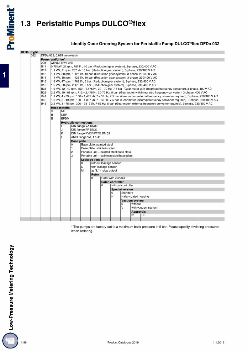
1.3 Peristaltic Pumps DULCO®flexLo
w-Pr
essu
re M
eter
ing Te
chno
logy
1
Identity Code Ordering System for Peristaltic Pump DULCO®flex DFDa 032
* The pumps are factory-set to a maximum back pressure of 5 bar. Please specify deviating pressures when ordering.
DFDa Type032 DFDa 032, 0.625 l/revolution
Power end/drive*000 without drive unitB11 0.75 kW, 21 rpm, 787 l/h, 10 bar (Reduction gear system), 3-phase, 230/400 V ACB12 1.1 kW, 21 rpm, 787 l/h, 15 bar (Reduction gear system), 3-phase, 230/400 V ACB13 1.1 kW, 30 rpm, 1,125 l/h, 10 bar (Reduction gear system), 3-phase, 230/400 V ACB14 1.1 kW, 38 rpm, 1,425 l/h, 10 bar (Reduction gear system), 3-phase, 230/400 V ACB15 1.5 kW, 47 rpm, 1,762 l/h, 5 bar (Reduction gear system), 3-phase, 230/400 V ACB16 1.5 kW, 58 rpm, 2,175 l/h, 5 bar (Reduction gear system), 3-phase, 230/400 V ACB31 1.5 kW, 12 - 42 rpm, 450 – 1,575 l/h, 20 – 70 Hz, 7.5 bar (Gear motor with integrated frequency converter), 3-phase, 400 V ACB32 2.2 kW, 19 - 66 rpm, 712 – 2,475 l/h, 20-70 Hz, 5 bar (Gear motor with integrated frequency converter), 3-phase, 400 V ACB41 1.1 kW, 4 - 39 rpm, 150 – 1,462 l/h, 7 – 65 Hz, 7.5 bar (Gear motor, external frequency converter required), 3-phase, 230/400 V ACB42 1.5 kW, 5 - 49 rpm, 190 – 1,837 l/h, 7 – 65 Hz, 7.5 bar (Gear motor, external frequency converter required), 3-phase, 230/400 V ACB43 2.2 kW, 8 - 75 rpm, 300 – 2812 l/h, 7-65 Hz, 5 bar (Gear motor, external frequency converter required), 3-phase, 230/400 V AC
Hose material0 NRB NBRE EPDM
Hydraulic connectionsI DIN flange VA DN32J DIN flange PP DN32K DIN flange PVDF/PTFE DN 32L ANSI flange VA, 1 1/4"
Base plate0 Base plate, painted steel1 Base plate, stainless steel2 Portable unit + painted steel base plate3 Portable unit + stainless steel base plate
Leakage sensor0 without leakage sensorL with leakage sensorM as "L" + relay output
Rotor0 Rotor with 2 shoes
Batch controller0 without controller
Special version0 StandardH Halar-coated housing
Vacuum system0 withoutV with vacuum system
Approvals01 CE
1-98 Product Catalogue 2019 1.1.2019

Low-
Pres
sure
Met
ering
Tech
nolog
y
1.3 Peristaltic Pumps DULCO®flex
1
Identity Code Ordering System for Peristaltic Pump DULCO®flex DFDa 040
* The pumps are factory-set to a maximum back pressure of 5 bar. Please specify deviating pressures when ordering.
DFDa Type040 DFDa 040, 1.33 l/revolution
Power end/drive*000 without drive unitC11 1.1 kW, 21 rpm, 1,676 l/h, 10 bar (Reduction gear system), 3-phase, 230/400 V ACC12 1.1 kW, 26 rpm, 2,075 l/h, 7.5 bar (Reduction gear system), 3-phase, 230/400 V ACC13 1.5 kW, 21 rpm, 1,676 l/h, 10 bar (Reduction gear system), 3-phase, 230/400 V ACC14 1.5 kW, 26 rpm, 2,075 l/h, 15 bar (Reduction gear system), 3-phase, 230/400 V ACC15 1.5 kW, 38 rpm, 3,032 l/h, 7.5 bar (Reduction gear system), 3-phase, 230/400 V ACC16 1.5 kW, 43 rpm, 3,431 l/h, 5 bar (Reduction gear system), 3-phase, 230/400 V ACC17 2.2 kW, 48 rpm, 3,830 l/h, 5 bar (Reduction gear system), 3-phase, 230/400 V ACC31 2.2 kW, 17 - 60 rpm, 1,356 – 4,788 l/h, 20-70 Hz, 5 bar (Gear motor with integrated frequency converter), 3-phase, 400 V ACC41 1.5 kW, 4 - 34 rpm, 320 – 2,713 l/h, 7-65 Hz, 5 bar (Gear motor, external frequency converter required), 3-phase, 230/400 V ACC42 2.2 kW, 4 - 34 rpm, 320 – 2,713 l/h, 7-65 Hz, 10 bar (Gear motor, external frequency converter required), 3-phase, 230/400 V ACC43 2.2 kW, 5 – 49 rpm, 400 – 3,910 l/h, 7 – 65 Hz, 5 bar (Gear motor, external frequency converter required), 3-phase, 230/400 V ACC44 3.0 kW, 7 - 62 rpm, 558 – 4,948 l/h, 7 – 64 Hz, 5 bar (Gear motor, external frequency converter required), 3-phase, 230/400 V AC
Hose material0 NRB NBRE EPDM
Hydraulic connectionsI DIN flange VA DN40J DIN flange PP DN40K DIN flange PVDF DN40L ANSI flange VA, 1 1/2"M ANSI flange PP 1 1/2"N ANSI flange PVDF/PTFE 1 1/2"
Base plate0 Base plate, painted steel1 Base plate, stainless steel2 Portable unit + painted steel base plate3 Portable unit + stainless steel base plate
Leakage sensor0 without leakage sensorL with leakage sensorM as "L" + relay output
Rotor0 Rotor with 2 shoes
Batch controller0 without controller
Special version0 StandardH Halar-coated housing
Vacuum system0 withoutV with vacuum system
Approvals01 CE
1.1.2019 Product Catalogue 2019 1-99

1.3 Peristaltic Pumps DULCO®flexLo
w-Pr
essu
re M
eter
ing Te
chno
logy
1
Identity Code Ordering System for Peristaltic Pump DULCO®flex DFDa 060
* The pumps are factory-set to a maximum back pressure of 5 bar. Please specify deviating pressures when ordering.
DFDa Type060 DFDa 060, 2.9 l/revolution
Power end/drive*000 without drive unitD11 2.2 kW, 22 rpm, 3.8 m³/h, 5 bar (Reduction gear system), 3-phase, 230/400 V ACD12 3.0 kW, 26 rpm, 4.5 m³/h, 5 bar (Reduction gear system), 3-phase, 230/400 V ACD13 4.0 kW, 22 rpm, 3.8 m³/h, 15 bar (Reduction gear system), 3-phase, 230/400 V ACD14 4.0 kW, 26 rpm, 4.5 m³/h, 10 bar (Reduction gear system), 3-phase, 230/400 V ACD15 4.0 kW, 32 rpm, 5.6 m³/h, 5 bar (Reduction gear system), 3-phase, 230/400 V ACD16 4.0 kW, 37 rpm, 6.4 m³/h, 5 bar (Reduction gear system), 3-phase, 230/400 V ACD17 5.5 kW, 47 rpm, 8.2 m³/h, 5 bar (Reduction gear system), 3-phase, 230/400 V ACD31 5.5 kW, 10 – 36 rpm, 1.7 – 6.3 m³/h, 20 – 70 Hz, 5 bar (Gear motor with integrated frequency converter), 3-phase, 400 V ACD32 7.5 kW, 19 – 66 rpm, 3.3 – 11.5 m³/h, 20 – 70 Hz, 5 bar (Gear motor with integrated frequency converter), 3-phase, 400 V ACD41 5.5 kW, 4 – 34 rpm, 0.7 – 5.9 m³/h, 20 – 70 Hz, 5 bar (Gear motor, external frequency converter required), 3-phase, 400/660 V ACD42 7.5 kW, 7 – 61 rpm, 1.2 – 10.6 m³/h, 20 – 70 Hz, 5 bar (Gear motor, external frequency converter required), 3-phase, 400/660 V AC
Hose material0 NRB NBRE EPDM
Hydraulic connectionsI DIN flange VA DN 50L ANSI flange VA DN 50J ANSI flange PP DN 50M ANSI flange PP DN 50U DIN flange VA, Halar-coated + PVDF inserts DN 50V ANSI flange VA, Halar coated + PVDF inserts DN 50
Base plate0 Base plate, painted steel1 Base plate, stainless steel2 Portable unit + painted steel base plate
Leakage sensor0 without leakage sensorL with leakage sensorM as "L" + relay output
Rotor0 Rotor with 2 shoes
Batch controller0 without controller
Special version0 StandardH Halar-coated housing
Vacuum system0 withoutV with vacuum system
Approvals01 CE
1-100 Product Catalogue 2019 1.1.2019

Low-
Pres
sure
Met
ering
Tech
nolog
y
1.3 Peristaltic Pumps DULCO®flex
1
Identity Code Ordering System for Peristaltic Pump DULCO®flex DFDa 070
* The pumps are factory-set to a maximum back pressure of 5 bar. Please specify deviating pressures when ordering.
DFDa Type070 DFDa 070, 6.7 l/revolution
Power end/drive*000 without drive unitE11 3.0 kW, 13.5 rpm, 5.4 m³/h, 5 bar (Reduction gear system), 3-phase, 230/400 V ACE12 4.0 kW, 18 rpm, 7.2 m³/h, 7.5 bar (Reduction gear system), 3-phase, 230/400 V ACE13 5.5 kW, 13.5 rpm, 5.4 m³/h, 15 bar (Reduction gear system), 3-phase, 230/400 V ACE14 5.5 kW, 26 rpm, 10.4 m³/h, 5 bar (Reduction gear system), 3-phase, 230/400 V ACE15 7.5 kW, 18 rpm, 7.2 m³/h, 15 bar (Reduction gear system), 3-phase, 230/400 V ACE16 7.5 kW, 26 rpm, 10.4 m³/h, 10 bar (Reduction gear system), 3-phase, 230/400 V ACE17 7.5 kW, 32 rpm, 12.8 m³/h, 7.5 bar (Reduction gear system), 3-phase, 230/400 V ACE18 7.5 kW, 40 rpm, 16 m³/h, 5 bar (Reduction gear system), 3-phase, 230/400 V ACE31 7.5 kW, 10 - 36 rpm, 4 - 14.4 m³/h, 20-70 Hz, 5 bar (Gear motor with integrated frequency converter), 3-phase, 400 V ACE41 7.5 kW, 4 - 34 rpm, 1.6 - 13.7 m³/h, 7-65 Hz, 5 bar (Gear motor, external frequency converter required), 3-phase, 400/660 V AC
Hose material0 NRB NBRE EPDM
Hydraulic connectionsI DIN flange VA DN65J DIN flange PP DN65L ANSI flange VA, 2 1/2"M ANSI flange PP 2 1/2"Q DIN flange VA Halar coated DN65R ANSI flange VA Halar coated 2 1/2"
Base plate0 Base plate, painted steel1 Base plate, stainless steel
Leakage sensor0 without leakage sensorL with leakage sensorM as "L" + relay output
Rotor0 Rotor with 2 shoes
Batch controller0 without controller
Special version0 StandardH Halar-coated housing
Vacuum system0 withoutV with vacuum system
Approvals01 CE
1.1.2019 Product Catalogue 2019 1-101

1.3 Peristaltic Pumps DULCO®flexLo
w-Pr
essu
re M
eter
ing Te
chno
logy
1
Identity Code Ordering System for Peristaltic Pump DULCO®flex DFDa 080
* The pumps are factory-set to a maximum back pressure of 5 bar. Please specify deviating pressures when ordering.
DFDa Type080 DFDa 080, 11.7 l/revolution
Power end/drive*000 without drive unitG11 4 kW, 12.5 rpm, 8.7 m³/h, 5 bar (Reduction gear system), 3-phase, 230/400 V ACG12 5.5 kW, 17.6 rpm, 12.3 m³/h, 5 bar (Reduction gear system), 3-phase, 230/400 V ACG13 7.5 kW, 12.5 rpm, 8.7 m³/h, 15 bar (Reduction gear system), 3-phase, 230/400 V ACG14 7.5 kW, 17.6 rpm, 12.3 m³/h, 10 bar (Reduction gear system), 3-phase, 230/400 V ACG15 7.5 kW, 20 rpm, 14 m³/h, 7.5 bar (Reduction gear system), 3-phase, 230/400 V ACG16 7.5 kW, 27.7 rpm, 19.4 m³/h, 5 bar (Reduction gear system), 3-phase, 230/400 V ACG17 11 kW, 30 rpm, 21 m³/h, 5 bar (Reduction gear system), 3-phase, 230/400 V AC
Hose material0 NRB NBRE EPDM
Hydraulic connectionsI DIN flange VA DN80J DIN flange PP DN80L ANSI flange VA 3"M ANSI flange PP 3"Q DIN flange VA Halar coated DN80R ANSI flange VA Halar coated 3"
Base plate0 Base plate, painted steel
Leakage sensor0 without leakage sensorL with leakage sensorM as "L" + relay output
Rotor0 Rotor with 2 shoes
Batch controller0 without controller
Special version0 Standard
Vacuum system0 withoutV with vacuum system
Approvals01 CE
1-102 Product Catalogue 2019 1.1.2019

Low-
Pres
sure
Met
ering
Tech
nolog
y
1.3 Peristaltic Pumps DULCO®flex
1
Identity Code Ordering System for Peristaltic Pump DULCO®flex DFDa 100
* The pumps are factory-set to a maximum back pressure of 5 bar. Please specify deviating pressures when ordering.
DFDa Type100 DFDa 100, 20.0 l/revolution
Power end/drive*000 without drive unitF11 7.5 kW, 12 rpm, 14.4 m³/h, 5 bar (Reduction gear system), 3-phase, 230/400 V ACF12 11 kW, 18 rpm, 21.6 m³/h, 5 bar (Reduction gear system), 3-phase, 230/400 V ACF13 15 kW, 12 rpm, 14.4 m³/h, 15 bar (Reduction gear system), 3-phase, 230/400 V ACF14 15 kW, 18 rpm, 21.6 m³/h, 10 bar (Reduction gear system), 3-phase, 230/400 V ACF15 15 kW, 23 rpm, 27.6 m³/h, 7.5 bar (Reduction gear system), 3-phase, 230/400 V ACF16 15 kW, 28 rpm, 33.6 m³/h, 5 bar (Reduction gear system), 3-phase, 230/400 V ACF17 18.5 kW, 30 rpm, 36 m³/h, 5 bar (Reduction gear system), 3-phase, 230/400 V AC
Hose material0 NRB NBRE EPDM
Hydraulic connectionsI DIN flange VA DN100J DIN flange PP DN100L ANSI flange VA 4"M ANSI flange PP 4"Q DIN flange VA Halar coated DN100R ANSI flange VA Halar coated 4"
Base plate0 Base plate, painted steel
Leakage sensor0 without leakage sensorL with leakage sensorM as "L" + relay output
Rotor0 Rotor with 2 shoes
Batch controller0 without controller
Special version0 Standard
Vacuum system0 withoutV with vacuum system
Approvals01 CE
1.1.2019 Product Catalogue 2019 1-103

1.3 Peristaltic Pumps DULCO®flexLo
w-Pr
essu
re M
eter
ing Te
chno
logy
1
Spare Parts for DFAa 003
Spare Parts for DFAa 008
Spare Parts for DFBa 010
Spare Parts for DFBa 013
Spare Parts for DFBa 016
Spare Parts for DFBa 019
1.3.7 Spare Parts
Order no.DFAa 003 silicone tube 1037107DFAa 003 Norprene tube A-60-F 1037144DFAa 003 Solva tube 1037145
Order no.DFAa 008 silicone tube 1037146DFAa 008 Norprene tube A-60-G 1037147DFAa 008 silicone tube 1037148DFAa 008 Solva tube 1037149
Order no.DFBa 010 NR tube 1037150DFBa 010 NBR tube 1037151DFBa 010 EPDM tube 1037152DFBa 010 NR-A tube 1037153DFBa 010 NBR-A tube 1037154DFBa 010 NORPRENE tube 1037155DFBa 010 HYPALON tube 1037156
Order no.DFBa 013 NR tube 1037157DFBa 013 NBR tube 1037158DFBa 013 EPDM tube 1037159DFBa 013 NR-A tube 1037160DFBa 013 NBR-A tube 1037161DFBa 013 NORPRENE tube 1037162DFBa 013 HYPALON tube 1037163
Order no.DFBa 016 NR tube 1037164DFBa 016 NBR tube 1037165DFBa 016 EPDM tube 1037166DFBa 016 NR-A tube 1037167DFBa 016 NBR-A tube 1037168DFBa 016 NORPRENE tube 1037169DFBa 016 HYPALON tube 1037171
Order no.DFBa 019 TYGON tube 1037172DFBa 019 NORPRENE tube 1037173
1-104 Product Catalogue 2019 1.1.2019

Low-
Pres
sure
Met
ering
Tech
nolog
y
1.3 Peristaltic Pumps DULCO®flex
1
Spare Parts for DFBa 022
Spare Parts for DFCa 030
Spare Parts for DFCa 040
Spare Parts for DFCa 050
Spare Parts for DFCa 060
Order no.DFBa 022 NR tube 1037175DFBa 022 NBR tube 1037176DFBa 022 EPDM tube 1037178DFBa 022 NR-A tube 1037179DFBa 022 NBR-A tube 1037180DFBa 022 NORPRENE tube 1037181DFBa 022 HYPALON tube 1037182
Order no.DFCa 030 NR tube 1037183DFCa 030 NBR tube 1037184DFCa 030 EPDM tube 1037185DFCa 030 NR-A tube 1037186DFCa 030 NBR-A tube 1037187DFCa 030 tube NORPRENE 1045073
Order no.DFCa 040 NR tube 1037192DFCa 040 NBR tube 1037193DFCa 040 EPDM tube 1037194DFCa 040 NR-A tube 1037195DFCa 040 NBR-A tube 1037196DFCa 040 NORPRENE tube 1037198
Order no.DFDa 040/DFCa 050 NR hose 1037199DFDa 040/DFCa 050 NBR hose 1037201DFDa 040/DFCa 050 EPDM hose 1037202DFCa 050 NR-A tube 1037203DFCa 050 NBR-A tube 1037204DFCa 050 tube NORPRENE 1045084
Order no.DFCa 060 NR tube 1037206DFCa 060 NBR tube 1037208DFCa 060 EPDM tube 1037209DFCa 060 NR-A tube 1037210DFCa 060 NBR-A tube 1037211DFCa 060 tube NORPRENE 1045085
1.1.2019 Product Catalogue 2019 1-105

1.3 Peristaltic Pumps DULCO®flexLo
w-Pr
essu
re M
eter
ing Te
chno
logy
1
Spare Parts for DFCa 070
Spare Parts for DFDa 025
Spare Parts for DFDa 032
Spare Parts for DFDa 040
Spare Parts for DFDa 060
Spare Parts for DFDa 070
Spare Parts DFDa 080
Spare Parts for DFDa 100
Order no.DFDa 070/DFCa 070 NR hose 1037213DFDa 070/DFCa 070 NBR hose 1037214DFDa 070/DFCa 070 EPDM hose 1037215DFCa 070 NR-A hose 1037216DFCa 070 NBR-A hose 1037217
Order no.DFDa 025 NR tube 1037219DFCa 025 NBR tube 1037220DFDa 025 EPDM tube 1037221
Order no.DFDa 032 NR tube 1037225DFCa 032 NBR tube 1037226DFDa 032 EPDM tube 1037227
Order no.DFDa 040/DFCa 050 NR hose 1037199DFDa 040/DFCa 050 NBR hose 1037201DFDa 040/DFCa 050 EPDM hose 1037202
Order no.DFDa 060 NR tube 1037236DFCa 060 NBR tube 1037237DFDa 060 EPDM tube 1037238
Order no.DFDa 070/DFCa 070 NR hose 1037213DFDa 070/DFCa 070 NBR hose 1037214DFDa 070/DFCa 070 EPDM hose 1037215
Order no.DFDa 080 hose NR 1041677DFDa 080 hose NBR 1041678DFDa 080 hose EPDM 1041679
Order no.DFDa 100 NR tube 1037247DFCa 100 NBR tube 1037248DFDa 100 EPDM tube 1037249
1-106 Product Catalogue 2019 1.1.2019

Low-
Pres
sure
Met
ering
Tech
nolog
y
1.4 Chemical Transfer Pumps
1
1.4Chemical Transfer Pumps
The right accessories offer even more: they increase the performance range, application options or the feed rates.This chapter includes chemical transfer pumps, which enable you to define the pump capacity precisely.The table will assist with quick selection. It is sorted by relevant key figures and details.
Selection Guide - Transfer Pumps:
1.4.1 Selection Guide
Capacity range see pageEccentric Screw Pump Spectra to 12,000 l/h → 1-108Centrifugal Pump von Taine® to 22,500 l/h → 1-111Air-Operated Diaphragm Pump Duodos to 6,700 l/h, 7 bar → 1-116Barrel Pump DULCO®Trans to 4,800 l/h → 1-119Rotary Lobe Pump ROTADOS 25 – 100 m3/h → 1-121
1.1.2019 Product Catalogue 2019 1-107

1.4 Chemical Transfer PumpsLo
w-Pr
essu
re M
eter
ing Te
chno
logy
1
Pump ultra-gently, meter precisely and with a wealth of applications.Capacity range 2.4 – 12,000 l/h, 12 – 3 bar
The eccentric screw pump Spectra has been designed for the transport of polymer solutions with a viscosity of up to 5,000 mPas. It is low-maintenance and can even be used if polymer solutions containing oil are to be metered. The pumps are equipped with gear motors and external fans and can be operated via an external frequency converter. Protect the pump from running dry.
Your benefits Low-pulsation pumping Feed rate is proportional to the speed Reversible pumping direction
Technical Details FKM stator Stainless steel (Cr-Ni-Mo 17-12-2) rotor Stainless steel housing for 12/2 - 12/100 Grey cast iron housing for 6/300 - 3/12000 Axial face seal Voltage: 3-phase, 230/400 VAC Degree of protection: IP55
Field of applicationWaste water treatment, sludge dewateringThe frequency converters do not form part of the Spectra scope of supply.
Without base plate
With base plate
1.4.2 Eccentric Screw Pump Spectra
The eccentric screw pump Spectra meters liquid polyelectrolytes in concentrated and dilute form. It can be used, for example, in waste water treatment or sludge dewatering.
pk_3_032
Delivery rate at3 bar
Maximumback pressure
Poweruptake
Order no.
bar kWSpectra 12/2 F 0.24…2.4 l/h 12 0.37 1025284Spectra 12/13 F 1.3…13.2 l/h 12 0.37 1025285Spectra 12/33 F 3.3…33 l/h 12 0.37 1025286Spectra 12/100 F 10…100 l/h 12 0.37 1025287Spectra 6/300 F 30…300 l/h 6 0.37 1025288Spectra 6/650 F 65…650 l/h 6 0.55 1025289Spectra 5/1400 F 140…1,400 l/h 5 0.75 1025290Spectra 3/3000 F 300…3,000 l/h 3 0.75 1025291Spectra 3/6500 F 650…6,500 l/h 3 1.50 1025292Spectra 3/12000 F 1,200…12,000 l/h 3 2.20 1025293
Delivery rate at3 bar
Maximumback pressure
Poweruptake
Order no.
bar kWSpectra 12/2 FB 0.24…2.4 l/h 12 0.37 1025294Spectra 12/13 FB 1.3…13.2 l/h 12 0.37 1025295Spectra 12/33 FB 3.3…33 l/h 12 0.37 1025296Spectra 12/100 FB 10…100 l/h 12 0.37 1025297Spectra 6/300 FB 30…300 l/h 6 0.37 1025298Spectra 6/650 FB 65…650 l/h 6 0.55 1025299Spectra 5/1400 FB 140…1,400 l/h 5 0.75 1025300Spectra 3/3000 FB 300…3,000 l/h 3 0.75 1025301Spectra 3/6500 FB 650…6,500 l/h 3 1.50 1025302Spectra 3/12000 FB 1,200…12,000 l/h 3 2.20 1025303
1-108 Product Catalogue 2019 1.1.2019

Low-
Pres
sure
Met
ering
Tech
nolog
y
1.4 Chemical Transfer Pumps
1
Frequency Converters for Spectra
The frequency converters do not form part of the Spectra scope of supply.
Motor Data
Technical Data
Recommended forpumps up to
Order no.
SK500E – 550 0.55 kW, 1 ph, 230 V,incl. control panel
0.37 kW 1010980
SK500E – 750 0.75 kW, 1 ph, 230 V,incl. control panel
0.55 kW 1010981
SK500E – 111 1.10 kW, 1 ph, 230 V,incl. control panel
0.75 kW 1025304
SK500E – 151 1.50 kW, 1 ph, 230 V,incl. control panel
1.10 kW 1010982
SK500E – 221 2.20 kW, 3 ph, 400 V,incl. control panel
2.20 kW 1025305
Electrical connection Frequency Enclosure rating Overheating protection Cooling230/400 VAC, 3 ph 4 - 89 Hz IP 55 3 PTC thermistors in winding external fan 1~, 230 VAC, 50 Hz
Weight DimensionsL x W x H (mm)
Housing material Material rot. parts Suction/discharge connection
kgSpectra 12/2 F 24 739 x 200 x 182 Cr Ni Mo 17 – 12 – 2 Cr Ni Mo 17 – 12 – 2 1/2″, femaleSpectra 12/13 F 24 739 x 200 x 182 Cr Ni Mo 17 – 12 – 2 Cr Ni Mo 17 – 12 – 2 1/2″, femaleSpectra 12/33 F 24 739 x 200 x 182 Cr Ni Mo 17 – 12 – 2 Cr Ni Mo 17 – 12 – 2 1/2″, femaleSpectra 12/100 F 24 739 x 200 x 182 Cr Ni Mo 17 – 12 – 2 Cr Ni Mo 17 – 12 – 2 1/2″, femaleSpectra 6/300 F 26 874 x 223 x 192 Grey cast iron Cr Ni Mo 17 – 12 – 2 1 1/4″, femaleSpectra 6/650 F 26 874 x 223 x 192 Grey cast iron Cr Ni Mo 17 – 12 – 2 1 1/4″, femaleSpectra 5/1400 F 26 874 x 223 x 192 Grey cast iron Cr Ni Mo 17 – 12 – 2 1 1/4″, femaleSpectra 3/3000 F 36 950 x 223 x 193 Grey cast iron Cr Ni Mo 17 – 12 – 2 1 1/4″, femaleSpectra 3/6500 F 56 1,172 x 237 x 224 Grey cast iron Cr Ni Mo 17 – 12 – 2 DN 50, flangeSpectra 3/12000 F 81 1,487 x 264 x 244 Grey cast iron Cr Ni Mo 17 – 12 – 2 DN 65, flangeSpectra 12/2 FB 28 739 x 220 x 232 Cr Ni Mo 17 – 12 – 2 Cr Ni Mo 17 – 12 – 2 1/2″, femaleSpectra 12/13 FB 28 739 x 220 x 232 Cr Ni Mo 17 – 12 – 2 Cr Ni Mo 17 – 12 – 2 1/2″, femaleSpectra 12/33 FB 28 739 x 220 x 232 Cr Ni Mo 17 – 12 – 2 Cr Ni Mo 17 – 12 – 2 1/2″, femaleSpectra 12/100 FB 28 739 x 220 x 232 Cr Ni Mo 17 – 12 – 2 Cr Ni Mo 17 – 12 – 2 1/2″, femaleSpectra 6/300 FB 33 874 x 230 x 242 Grey cast iron Cr Ni Mo 17 – 12 – 2 1 1/4″, femaleSpectra 6/650 FB 33 874 x 230 x 242 Grey cast iron Cr Ni Mo 17 – 12 – 2 1 1/4″, femaleSpectra 5/1400 FB 33 874 x 230 x 242 Grey cast iron Cr Ni Mo 17 – 12 – 2 1 1/4″, femaleSpectra 3/3000 FB 44 950 x 230 x 242 Grey cast iron Cr Ni Mo 17 – 12 – 2 1 1/4″, femaleSpectra 3/6500 FB 67 1,172 x 237 x 274 Grey cast iron Cr Ni Mo 17 – 12 – 2 DN 50, flangeSpectra 3/12000 FB 96 1,487 x 265 x 294 Grey cast iron Cr Ni Mo 17 – 12 – 2 DN 65, flange
1.1.2019 Product Catalogue 2019 1-109

1.4 Chemical Transfer PumpsLo
w-Pr
essu
re M
eter
ing Te
chno
logy
1
Spare PartsOrder no.
Stator FKM for Spectra 12/2 1025306Stator FKM for Spectra 12/13 1025307Stator FKM for Spectra 12/30, 12/33 1025308Stator made of FKM for Spectra 12/100 1025309Stator FKM for Spectra 6/300, 6/650 1025310Stator FKM for Spectra 5/1400 1025312Stator FKM for Spectra 3/3000 1025313Stator made of FKM for Spectra 3/6500 1025314Stator FKM for Spectra 3/12000 1025315Rotor Cr Ni Mo 17-12-2 for Spectra 12/2 1025316Rotor Cr Ni Mo 17-12-2 for Spectra 12/13 1025317Rotor Cr Ni Mo 17-12-2 for Spectra 12/30, 12/33 1025318Rotor made of Cr Ni Mo 17-12-2 for Spectra 12/100 1025319Rotor Cr Ni Mo 17-12-2 for Spectra 6/300, 6/650 1025320Rotor Cr Ni Mo 17-12-2 for Spectra 5/1400 1025322Rotor Cr Ni Mo 17-12-2 for Spectra 3/3000 1025323Rotor made of Cr Ni Mo 17-12-2 for Spectra 3/6500 1025324Rotor Cr Ni Mo 17-12-2 for Spectra 3/12000 1025325Spare parts kit for axial face seal for Spectra 12/2 - 12/100 1025326Spare parts kit for mech. seal for Spectra 6/300 - 5/1400 1025330Spare parts kit for mech. seal for Spectra 3/3000 1025333Spare parts kit for axial face seal for Spectra 3/6500 1025334Spare parts kit for mech. seal for Spectra 3/12000 1025335Spare parts kit for pin joint for Spectra 12/2 - 12/100 1025346Pin joints spare parts kit for Spectra 6/300 - 5/1400 1025350Pin joints spare parts kit for Spectra 3/3000 1025353Spare parts kit for pin joint for Spectra 3/6500 1025354Pin joints spare parts kit for Spectra 3/12000 1025355
1-110 Product Catalogue 2019 1.1.2019

Low-
Pres
sure
Met
ering
Tech
nolog
y
1.4 Chemical Transfer Pumps
1
The safe and high-quality solution when liquid media need to be pumped leak-free.Capacity range up to 22,500 l/h, discharge lift up to 23.5 m WC
The von Taine® pump is a solenoid-coupled centrifugal pump. Thanks to the solenoid coupling, the pump transports the liquid medium from storage tank to storage tank without any leaks or even from a tank to a discharge line. The von Taine® centrifugal pump transports media at up to 22,500 l/h and up to a discharge lift of 23.5 metres. As the pump capacity is highly dependent on the back pressure, always observe the performance curve.Important noteCheck the material tolerability when selecting your pump. Take into consideration the density, viscosity and temperature of the medium to be transported. Please also note: The transported media should not contain any solid fractions. The pump is not self-priming and requires a feed.Your benefits Safe and reliable: Leak-free pumping of liquid chemicals Coupling between motor and impeller via magnetic coupling
Technical Details Pump head made of PP or PVDF FKM or EPDM seal The pump is not self-priming and requires a feed Protect the pump from running dry Hydraulic connectors with pipe threading as per DIN ISO 228-1
Field of applicationLeak-free pumping of liquid chemicals
von Taine®, PP/FKM Version
von Taine®, PVDF/FKM Version
1.4.3 Centrifugal Pump von Taine®
The solenoid-coupled centrifugal pump von Taine® for the pumping of liquid media works safely and reliably: liquid media are pumped leak-free.
pk_3_026
Feed rate atmax. pressure
Feed liftmax.
Power up-take
Voltage/fre-quency
Weight Order no.
l/h m kW kgvon Taine® 0502 PP/FKM 1,800 4.5 0.06 1~/230 V/50 Hz 2.7 1023089von Taine® 0807 PP/FKM 6,600 7.9 0.25 3~/400 V/50 Hz 5.0 1023090von Taine® 1010 PP/FKM 9,600 10.0 0.37 3~/400 V/50 Hz 7.6 1023091von Taine® 1313 PP/FKM 13,200 13.2 0.65 3~/400 V/50 Hz 8.7 1023092von Taine® 1820 PP/FKM 19,500 18.1 1.10 3~/400 V/50 Hz 16.0 1023093von Taine® 2323 PP/FKM 22,500 23.5 1.50 3~/400 V/50 Hz 17.0 1023094
Feed rate atmax. pressure
Feed liftmax.
Power up-take
Voltage/fre-quency
Weight Order no.
l/h m kW kgvon Taine® 0502 PVDF/FKM 1,800 4.5 0.06 1~/230 V/50 Hz 2.8 1023095von Taine® 0807 PVDF/FKM 6,600 7.9 0.25 3~/400 V/50 Hz 5.2 1023096von Taine® 1010 PVDF/FKM 9,600 10.0 0.37 3~/400 V/50 Hz 8.0 1023097von Taine® 1313 PVDF/FKM 13,200 13.2 0.65 3~/400 V/50 Hz 9.0 1023098von Taine® 1820 PVDF/FKM 19,500 18.1 1.10 3~/400 V/50 Hz 16.7 1023099von Taine® 2323 PVDF/FKM 22,500 23.5 1.50 3~/400 V/50 Hz 17.7 1023100
1.1.2019 Product Catalogue 2019 1-111

1.4 Chemical Transfer PumpsLo
w-Pr
essu
re M
eter
ing Te
chno
logy
1
von Taine®, PP/EPDM Version
von Taine®, PVDF/EPDM Version
Parameters For Use
Feed rate atmax. pressure
Feed liftmax.
Power up-take
Voltage/fre-quency
Weight Order no.
l/h m kW kgvon Taine® 0502 PP/EPDM 1,800 4.5 0.06 1~/230 V/50 Hz 2.7 1028551von Taine® 0807 PP/EPDM 6,600 7.9 0.25 3~/400 V/50 Hz 5.0 1028552von Taine® 1010 PP/EPDM 9,600 10.0 0.37 3~/400 V/50 Hz 7.6 1028553von Taine® 1313 PP/EPDM 13,200 13.2 0.65 3~/400 V/50 Hz 8.7 1028564von Taine® 1820 PP/EPDM 19,500 18.1 1.10 3~/400 V/50 Hz 16.0 1028565von Taine® 2323 PP/EPDM 22,500 23.5 1.50 3~/400 V/50 Hz 17.0 1028566
Feed rate atmax. pressure
Feed liftmax.
Power up-take
Voltage/fre-quency
Weight Order no.
l/h m kW kgvon Taine® 0502 PVDF/EPDM 1,800 4.5 0.06 1~/230 V/50 Hz 2.8 1028567von Taine® 0807 PVDF/EPDM 6,600 7.9 0.25 3~/400 V/50 Hz 5.2 1028568von Taine® 1010 PVDF/EPDM 9,600 10.0 0.37 3~/400 V/50 Hz 8.0 1028569von Taine® 1313 PVDF/EPDM 13,200 13.2 0.65 3~/400 V/50 Hz 9.0 1028570von Taine® 1820 PVDF/EPDM 19,500 18.1 1.10 3~/400 V/50 Hz 16.7 1028571von Taine® 2323 PVDF/EPDM 22,500 23.5 1.50 3~/400 V/50 Hz 17.7 1028572
Medium temperature max. Maximum density Max. viscosity Max. system pressure at 20° C °C kg/dm3 mPas bar
von Taine® 0502 PP 80 1.25…1.35 20 1.0von Taine® 0807 PP 80 1.20…1.80 20 2.5von Taine® 1010 PP 80 1.60…2.00 20 2.5von Taine® 1313 PP 80 1.60…1.90 20 2.5von Taine® 1820 PP 80 1.10…1.80 20 5.0von Taine® 2323 PP 80 1.00…2.00 20 5.0von Taine® 0502 PVDF 95 1.25…1.35 20 1.0von Taine® 0807 PVDF 95 1.20…1.80 20 2.5von Taine® 1010 PVDF 95 1.60…2.00 20 2.5von Taine® 1313 PVDF 95 1.60…1.90 20 2.5von Taine® 1820 PVDF 95 1.10…1.80 20 5.0von Taine® 2323 PVDF 95 1.00…2.00 20 5.0
1-112 Product Catalogue 2019 1.1.2019

Low-
Pres
sure
Met
ering
Tech
nolog
y
1.4 Chemical Transfer Pumps
1
Characteristic Curves
pk_2_080_1Delivered quantity [l/h] as a function of the delivery head [m WC]
pk_2_115Delivered quantity [l/h] as a function of the delivery head [m WC]
1.1.2019 Product Catalogue 2019 1-113

1.4 Chemical Transfer PumpsLo
w-Pr
essu
re M
eter
ing Te
chno
logy
1
Dimensions
pk_3_027
von Taine® 0502 PVDF
von Taine® 0807 PVDF
von Taine® 1010 PVDF
von Taine® 1313 PVDF
von Taine® 1820 PVDF
von Taine® 2323 PVDF
Discharge connector (D) G 1″ G 1 1/4″ G 1 1/2″ G 1 1/2″ G 2″ G 2″Suction connector (S) G 1 1/4″ G 1 1/4″ G 2″ G 2″ G 2 1/4″ G 2 1/4″L mm 240 283 346 350 455 455B mm 120 138 163 163 205 205H mm 145 185 181 191 216 216a mm 37.0 45.0 58.5 58.5 70.0 70.0b mm 29.5 29.5 56.0 56.0 70.0 70.0c mm 60.0 70.0 82.0 82.0 104.5 104.5d mm 65.5 86.0 104.0 104.0 134.5 134.5e mm 129 50 106 106 115 115f mm 78 71 74 74 100 100g mm 91 91 114 114 130 130h mm 6.5 8.5 8.5 8.5 10.0 10.0i mm 92 135 136.5 135 160 160Enclosure rating IP 55 IP 55 IP 55 IP 55 IP 55 IP 55Min. flow l/h 30 60 60 60 90 120
1-114 Product Catalogue 2019 1.1.2019

Low-
Pres
sure
Met
ering
Tech
nolog
y
1.4 Chemical Transfer Pumps
1
Spare Parts KitsOrder no.
PP/FKM liquid end for von Taine® 0502 1023978PP/FKM liquid end forr von Taine® 0807 1023979PP/FKM liquid end for von Taine® 1010 1023980PP/FKM liquid end for von Taine® 1313 1023981PP/FKM liquid end for von Taine® 1820 1023982PP/FKM liquid end for von Taine® 2323 1023983PVDF/FKM liquid end for von Taine® 0502 1023994PVDF/FKM liquid end for von Taine® 0807 1023995PVDF/FKM liquid end for von Taine® 1010 1023996PVDF/FKM liquid end for von Taine® 1313 1023997PVDF/FKM liquid end for von Taine® 1820 1023998PVDF/FKM liquid end for von Taine® 2323 1023999
Order no.PP/EPDM liquid end for von Taine® 0502 1028573PP/EPDM liquid end for von Taine® 0807 1028574PP/EPDM liquid end forvon Taine® 1010 1028575PP/EPDM liquid end for von Taine® 1313 1028576PP/EPDM liquid end for von Taine® 1820 1028577PP/EPDM liquid end for von Taine® 2323 1028578PVDF/EPDM liquid end for von Taine® 0502 1028579PVDF/EPDMliquid end for von Taine® 0807 1028580PVDF/EPDM liquid end for von Taine® 1010 1028581PVDF/EPDM liquid end for von Taine® 1313 1028582PVDF/EPDM liquid end for von Taine® 1820 1028583PVDF/EPDM liquid end for von Taine® 2323 1028584
Order no.Motor for von Taine® 0502 1024000Motor for von Taine® 0807 1024001Motor for von Taine® 1010 1024002Motor for von Taine® 1313 1024003Motor for von Taine® 1820 1024004Motor for von Taine® 2323 1024005
1.1.2019 Product Catalogue 2019 1-115
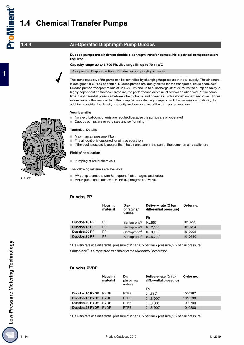
1.4 Chemical Transfer PumpsLo
w-Pr
essu
re M
eter
ing Te
chno
logy
1
Duodos pumps are air-driven double diaphragm transfer pumps. No electrical components are required.Capacity range up to 6,700 l/h, discharge lift up to 70 m WC
The pump capacity of the pump can be controlled by changing the pressure in the air supply. The air control is designed for oil-free operation. Duodos pumps are ideally suited for the transport of liquid chemicals. Duodos pumps transport media at up 6,700 l/h and up to a discharge lift of 70 m. As the pump capacity is highly dependent on the back pressure, the performance curve must always be observed. At the same time, the differential pressure between the hydraulic and pneumatic sides should not exceed 2 bar. Higher values reduce the service life of the pump. When selecting pumps, check the material compatibility. In addition, consider the density, viscosity and temperature of the transported medium.
Your benefits No electrical components are required because the pumps are air-operated Duodos pumps are run-dry safe and self-priming
Technical Details Maximum air pressure 7 bar The air control is designed for oil-free operation If the back pressure is greater than the air pressure in the pump, the pump remains stationary
Field of application
Pumping of liquid chemicals
The following materials are available: PP pump chambers with Santoprene® diaphragms and valves PVDF pump chambers with PTFE diaphragms and valves
Duodos PP
* Delivery rate at a differential pressure of 2 bar (0.5 bar back pressure, 2.5 bar air pressure).Santoprene® is a registered trademark of the Monsanto Corporation.
Duodos PVDF
* Delivery rate at a differential pressure of 2 bar (0.5 bar back pressure, 2.5 bar air pressure).
1.4.4 Air-Operated Diaphragm Pump Duodos
Air-operated Diaphragm Pump Duodos for pumping liquid media.
pk_2_062
Housing material
Dia-phragms/valves
Delivery rate (2 bar differential pressure)
Order no.
l/hDuodos 10 PP PP Santoprene® 0…650* 1010793Duodos 15 PP PP Santoprene® 0…2,000* 1010794Duodos 20 PP PP Santoprene® 0…3,000* 1010795Duodos 25 PP PP Santoprene® 0…6,700* 1010796
Housing material
Dia-phragms/valves
Delivery rate (2 bar differential pressure)
Order no.
l/hDuodos 10 PVDF PVDF PTFE 0…650* 1010797Duodos 15 PVDF PVDF PTFE 0…2,000* 1010798Duodos 20 PVDF PVDF PTFE 0…3,000* 1010799Duodos 25 PVDF PVDF PTFE 0…6,700* 1010800
1-116 Product Catalogue 2019 1.1.2019

Low-
Pres
sure
Met
ering
Tech
nolog
y
1.4 Chemical Transfer Pumps
1
Parameters For Use
Characteristic Curves
pk_2_114Feed lift [m WC] over feed rate [l/h] at 7 bar air supply
Spare Parts Kits
Spare part kits for pneumatics comprising Seals O-rings Clamp collars Air control valve
Min. temperature Max. temperature Max. viscosity °C °C mPas
Duodos 10 PP 5 65 200Duodos 10 PVDF -13 93 200Duodos 15 PP 5 65 200Duodos 15 PVDF -13 93 200Duodos 20 PP 5 65 200Duodos 20 PVDF -13 93 200Duodos 25 PP 5 65 200Duodos 25 PVDF -13 93 200
Order no.Spare parts kit, pneumatics for Duodos 10 PP/PVDF 1010810Spare parts kit, pneumatics for Duodos 15/20 PP/PVDF 1010811Spare parts kit, pneumatics for Duodos 25 PP/PVDF 1010813
1.1.2019 Product Catalogue 2019 1-117

1.4 Chemical Transfer PumpsLo
w-Pr
essu
re M
eter
ing Te
chno
logy
1
Spare part kits for the liquid end comprising Diaphragms Valve balls Seals
Dimensions
Order no.Spare parts kit, liquid end for Duodos 10 PP 1010801Spare parts kit, liquid end for Duodos 15 PP 1010802Spare parts kit, liquid end for Duodos 20 PP 1010803Spare parts kit, liquid end for Duodos 25 PP 1010804Spare parts kit, liquid end for Duodos 10 PVDF 1010806Spare parts kit, liquid end for Duodos 15 PVDF 1010807Spare parts kit, liquid end for Duodos 20 PVDF 1010808Spare parts kit, liquid end for Duodos 25 PVDF 1010809
pk_2_072
pk_2_106
pk_2_107
Duodos 10 Duodos 15 Duodos 20 Duodos 25A mm 79 103 103 172B mm 140 179 179 296C mm 32 44 60 92D mm 198 287 339 527E mm 167 243 279 435F mm 87 140 163 249G mm 19 35 46 64H mm 32 44 60 92I mm 78 143 143 130J mm 178 258 300 433K mm 89 129 150 216L mm 33 46 57 123M mm 66 143 143 102Discharge connector 1/2″ NPT 1″ BSP 1 1/2″ BSP 1″ANSI flangeSuction connector 1/2″ NPT 1″ BSP 1 1/2″ BSP 1″ANSI flangeAir consumption m3/h 0.5…11 3.5…27 7.0…34 8.5…77Differential pressure bar 2 2 2 2Air connection 1/4″ NPT 1/4″ NPT 1/4″ NPT 1/2″ NPTWeight (PP) kg 2 8 9 24Weight (PVDF) kg 2.5 9.0 9.5 29.0
1-118 Product Catalogue 2019 1.1.2019

Low-
Pres
sure
Met
ering
Tech
nolog
y
1.4 Chemical Transfer Pumps
1
Barrel pumps are the ideal solution for moving liquids.Pump capacity according to size 2,800 – 6,600 l/h
DULCO®Trans is used for bottling, draining and transferring liquids from canisters, hobbocks, drums, storage tanks and containers.Included in the scope of supply: Metering hose with pump nozzle.
Your benefits Reliable pumping of liquid chemicals Pump sets available for different delivery containers Pump nozzle for convenient filling of liquids Undervoltage trigger prevents unintentional start-up after an interruption to the operating voltage. The overcurrent safety switch prevents overloading of the motor.
Technical Details Pump available in PP or PVDF PVC hose or multi-purpose chemical hose Pump nozzle made of PP or PVDF Protect the pump from running dry Pumps cannot be remotely controlled
Field of applicationBarrel pump for bottling, emptying and transferring liquids from canisters, drums and containers.
Materials in Contact With the MediumThe following components come into contact with the liquids:
DULCO®Trans PP Version
DULCO®Trans PVDF Version
* The specified delivery rate includes hose and tap, determined using water as the medium at room temperature.
1.4.5 Barrel Pump DULCO®Trans
The application range of the DULCO®Trans depends on the chemical resistance of the materials used.
pk_3_029
PP version PVDF versionExternal and internal pipe, tap Polypropylene PVDFDrive shaft Hastelloy C Hastelloy CRotor PP PVDFMechanical seal PTFE PTFEO-rings FKM FKMMetering hose PVC multi-purpose chemical hose
Feed rate max. Feed lift max. Order no.l/h m
DULCO®Trans 32/700 PP 2,800 * 10 1098490DULCO®Trans 41/1000 PP 5,400 * 11 1098491DULCO®Trans 41/1200 PP 6,600 * 16 1098489
Feed rate max. Feed lift max. Order no.l/h m
DULCO®Trans 32/700 PVDF 2800 l/h * 10 1098492DULCO®Trans 41/1000 PVDF 5400 l/h * 11 1098493DULCO®Trans 41/1200 PVDF 6600 l/h * 16 1098494
1.1.2019 Product Catalogue 2019 1-119
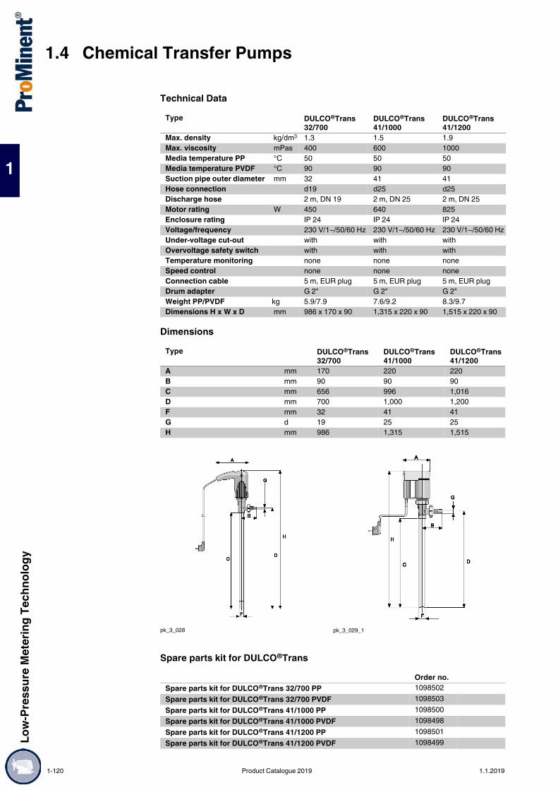
1.4 Chemical Transfer PumpsLo
w-Pr
essu
re M
eter
ing Te
chno
logy
1
Technical Data
Dimensions
Spare parts kit for DULCO®Trans
Type DULCO®Trans 32/700
DULCO®Trans 41/1000
DULCO®Trans 41/1200
Max. density kg/dm3 1.3 1.5 1.9Max. viscosity mPas 400 600 1000Media temperature PP °C 50 50 50Media temperature PVDF °C 90 90 90Suction pipe outer diameter mm 32 41 41Hose connection d19 d25 d25Discharge hose 2 m, DN 19 2 m, DN 25 2 m, DN 25Motor rating W 450 640 825Enclosure rating IP 24 IP 24 IP 24Voltage/frequency 230 V/1~/50/60 Hz 230 V/1~/50/60 Hz 230 V/1~/50/60 HzUnder-voltage cut-out with with withOvervoltage safety switch with with withTemperature monitoring none none noneSpeed control none none noneConnection cable 5 m, EUR plug 5 m, EUR plug 5 m, EUR plugDrum adapter G 2" G 2" G 2"Weight PP/PVDF kg 5.9/7.9 7.6/9.2 8.3/9.7Dimensions H x W x D mm 986 x 170 x 90 1,315 x 220 x 90 1,515 x 220 x 90
Type DULCO®Trans 32/700
DULCO®Trans 41/1000
DULCO®Trans 41/1200
A mm 170 220 220B mm 90 90 90C mm 656 996 1,016D mm 700 1,000 1,200F mm 32 41 41G d 19 25 25H mm 986 1,315 1,515
pk_3_028 pk_3_029_1
Order no.Spare parts kit for DULCO®Trans 32/700 PP 1098502Spare parts kit for DULCO®Trans 32/700 PVDF 1098503Spare parts kit for DULCO®Trans 41/1000 PP 1098500Spare parts kit for DULCO®Trans 41/1000 PVDF 1098498Spare parts kit for DULCO®Trans 41/1200 PP 1098501Spare parts kit for DULCO®Trans 41/1200 PVDF 1098499
1-120 Product Catalogue 2019 1.1.2019
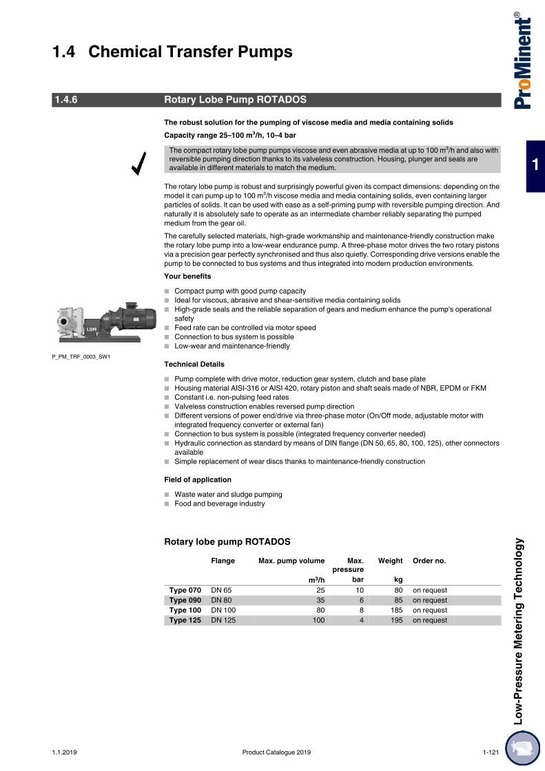
Low-
Pres
sure
Met
ering
Tech
nolog
y
1.4 Chemical Transfer Pumps
1
The robust solution for the pumping of viscose media and media containing solidsCapacity range 25–100 m³/h, 10–4 bar
The rotary lobe pump is robust and surprisingly powerful given its compact dimensions: depending on the model it can pump up to 100 m³/h viscose media and media containing solids, even containing larger particles of solids. It can be used with ease as a self-priming pump with reversible pumping direction. And naturally it is absolutely safe to operate as an intermediate chamber reliably separating the pumped medium from the gear oil.The carefully selected materials, high-grade workmanship and maintenance-friendly construction make the rotary lobe pump into a low-wear endurance pump. A three-phase motor drives the two rotary pistons via a precision gear perfectly synchronised and thus also quietly. Corresponding drive versions enable the pump to be connected to bus systems and thus integrated into modern production environments.Your benefits Compact pump with good pump capacity Ideal for viscous, abrasive and shear-sensitive media containing solids High-grade seals and the reliable separation of gears and medium enhance the pump's operational
safety Feed rate can be controlled via motor speed Connection to bus system is possible Low-wear and maintenance-friendly
Technical Details Pump complete with drive motor, reduction gear system, clutch and base plate Housing material AISI-316 or AISI 420, rotary piston and shaft seals made of NBR, EPDM or FKM Constant i.e. non-pulsing feed rates Valveless construction enables reversed pump direction Different versions of power end/drive via three-phase motor (On/Off mode, adjustable motor with
integrated frequency converter or external fan) Connection to bus system is possible (integrated frequency converter needed) Hydraulic connection as standard by means of DIN flange (DN 50, 65, 80, 100, 125), other connectors
available Simple replacement of wear discs thanks to maintenance-friendly construction
Field of application Waste water and sludge pumping Food and beverage industry
Rotary lobe pump ROTADOS
1.4.6 Rotary Lobe Pump ROTADOS
The compact rotary lobe pump pumps viscose and even abrasive media at up to 100 m³/h and also with reversible pumping direction thanks to its valveless construction. Housing, plunger and seals are available in different materials to match the medium.
P_PM_TRF_0003_SW1
Flange Max. pump volume Max.pressure
Weight Order no.
m3/h bar kgType 070 DN 65 25 10 80 on requestType 090 DN 80 35 6 85 on requestType 100 DN 100 80 8 185 on requestType 125 DN 125 100 4 195 on request
1.1.2019 Product Catalogue 2019 1-121

1.4 Chemical Transfer PumpsLo
w-Pr
essu
re M
eter
ing Te
chno
logy
1
Filling a Day Tank
The von Taine® centrifugal pump is switched on and off automatically by the level control facility in the day tank.
pk_3_050
Task and requirements
Automatically filling service tanks with 32 % hydrochloric acid solution
Operating conditions Indoor operation Automatic activation of pump
Application information Centrifugal pump controlled by level control facility in metering tank The centrifugal pump is not self-priming and requires feed Hydrochloric acid compatibility of materials must be ensured (PP, PVDF; EPDM) Provide dry-running protection facility for centrifugal pump
Solution vonTaine® 1820 PP centrifugal pump Service tank with level control
Benefits Safe handling of hydrochloric acid Fully automatic operation with minimum personnel and maintenance requirements
1.4.7 Application Examples
Product: von Taine® centrifugal pumpMetered medium: 32% hydrochloric acid solutionSector: FoodApplication: Chemical transfer
1-122 Product Catalogue 2019 1.1.2019

Low-
Pres
sure
Met
ering
Tech
nolog
y
1.4 Chemical Transfer Pumps
1
Filling Day Tanks
The level control facility for the day tanks opens the solenoid valves when the level drops below minimum. With decreasing back pressure, the Duodos pump automatically begins to pump medium into the metering line and switches off when the maximum level in the tank is reached and the solenoid valve is switched off.
pk_3_051
Task and requirements
Automatic filling of day tanks with detergent
Operating conditions Compressed air necessary for operating compressed air diaphragm pump Automatic filling of day tanks
Application information Compressed air diaphragm-type pump controlled by level control facility in metering tank The compressed air diaphragm pump is self-priming Also suitable for viscous media The level control facility for the day tanks opens the solenoid valves when the level drops below
minimum. With decreasing back pressure, the compressed air diaphragm-type pump automatically begins to pump medium into the metering line and switches off when the maximum level in the tank is reached and the solenoid valve is switched off
Solution Duodos air-operated diaphragm pump Day tank with level control
Benefits Simplified logistics through central storage Fully automatic operation with minimum personnel and maintenance requirements
Product: Duodos air-operated diaphragm pumpMetered medium: DetergentSector: LaundryApplication: Chemical transfer
1.1.2019 Product Catalogue 2019 1-123

1.4 Chemical Transfer PumpsLo
w-Pr
essu
re M
eter
ing Te
chno
logy
1
Deacidification of Potable Water
AP_PTW_0001_SW
Problems and requirements Feed of abrasive lime milk into potable water tanks Deacidification of the potable water
Operating conditions The lime milk comes as a 10% suspension The pH in the application tank is continuously measured
Notes on use The peristaltic pump is self-priming The pump is controlled by a pH measuring unit Speed reduction to extend the service life of the hose
Solution DULCO®flex DFCa 040 type peristaltic pump Hose material: NR (natural rubber)
Benefits Reliable feed of lime milk Fully automatic operation with minimum personnel and maintenance requirements
Product DULCO®flex peristaltic pumpFeed chemical Lime milk 10%Sector: Potable waterApplication Feed of abrasive chemicals
1-124 Product Catalogue 2019 1.1.2019

Low-
Pres
sure
Met
ering
Tech
nolog
y
1.5 Accessories for Low-Pressure Metering Pumps
1
1.5Accessories for Low-Pressure Metering Pumps
Digital fluid management with the DULCOnneX platform
The DULCOnnect® IoT/Industry 4.0 module lets you securely and reliably monitor pumps, sensors, controllers and disinfection systems by smartphone, tablet or computer, independently of their location. Adjustable alarms inform users promptly by e-mail or push notification about important events and the web portal provides access to current and historical unit data at all times. The data can be exported in CSV format, as an Excel document or as a PDF report, for instance to comply with statutory documentation obligations. Flexible management of devices enables them to be sensibly grouped and thus viewed at a glance.All key device-specific values can be monitored and documented alongside error and alarm statuses. With pumps, this includes pressure and the metered volume. With controllers, this includes the values of the connected sensors (for example pH, ORP and turbidity) and, with UV disinfection systems, the radiation intensity and temperature are recorded, among other things.Communication with the connected devices is via Ethernet or via CANopen at field bus level. The DULCOnnect® IoT/Industry 4.0 module securely sends all data with SSL/TLS encryption by GSM or Wi-Fi, enabling real-time monitoring of global systems. User-specific data and measured values are stored in separate databases and measured values are internally anonymised to achieve maximum data security.The DULCOnneX web portal can be accessed via https://dulconnect.prominent.com .
Your benefits Web-based fluid management Simple commissioning Communication via GSM or Wi-FiList of devices already available for DULCOnneX* Solenoid-driven metering pumps gamma/ X, gamma/ XL, delta® Motor-driven metering pumps Sigma X Control type Controllers DULCOMETER® diaLog DACb, AEGIS II, SlimFLEX 5a UV system Dulcodes LP* additional devices will be available shortly
1.5.1 IoT Module DULCOnnect®
Our DULCOnnect® module enables all smart products to be connected to our web-based fluid management platform.
Order no.DULCOnnect® GSM with SIM card (device on loan) 1093105DULCOnnect® GSM without SIM card 1080800DULCOnnect® Wi-Fi with GSM router & SIM card (unit on loan) on demandDULCOnnect® Wi-Fi (proprietary Wi-Fi network) on demand
1.1.2019 Product Catalogue 2019 1-125

1.5 Accessories for Low-Pressure Metering PumpsLo
w-Pr
essu
re M
eter
ing Te
chno
logy
1
Your reliable control unit: unobtrusively measures, monitors and detects faults.For the measurement of pulsating volumetric flows within the range of 0.03 ml/stroke to 10 ml/stroke
The device works on the ultrasound measuring principle. It was developed specifically for measuring small pulsating volumetric flows. It is installed around 30 cm downstream of the metering pump, so that there is still sufficient pulsation in the flow. All liquids that conduct ultrasound waves can be measured.
Your benefits Maximum chemical resistance by the use of PVDF and PTFE No electrical conductivity of the medium is needed Measurement above stroke volumes of approx. 30 µl Detection of gas bubbles in the feed chemical No bottlenecks in the measuring tube. Media with small undissolved particles or with increased viscosity
can be measured A 0/4 -20 mA current output and a frequency output are available for remote transmission of the
measured values. Use as a single stroke monitor with feedback to the pump. This ensures that the metering stroke is
performed within an adjustable lower and upper limit Summation of the metering volume measured with stroke counter Intuitive user guidance and simple programming
Technical Details 2 LEDs for status display and stroke feedback 2-line graphic display 0/4-20 mA standard signal and 0 – 10 kHz frequency output for remote transmission of the measured
value Compact, chemically-resistant plastic housing Measuring accuracy ± 2 % if the device has been calibrated to the chemical to be measured. Max.
operating pressure 16 bar.
Field of application Measurement of the chemical consumption, for example in surface treatment. Guaranteed metering, for example in the paper industry. Measured value transmission and pump control by the central control system. Measurement of aggressive chemicals. Not suitable for liquids, which have minimal acoustic conductivity, e.g. sodium hydroxide (NaOH) with
a concentration of greater than around approx. 20%. We recommend first testing the measurability with emulsions and suspensions. Media like chlorine dioxide liquids, which can penetrate through PVDF, can lead to shorter
lifetime of the transducers.
1.5.2 Flow Meter DulcoFlow®
The flow meter DulcoFlow® reliably measures pulsating flows in the range above 0.03 ml/stroke based on the ultrasound measuring principle. The flow meter achieves maximum chemical resistance, as all wetted parts are made of PVDF and PTFE.
P_DFl_0002_SW1
1-126 Product Catalogue 2019 1.1.2019
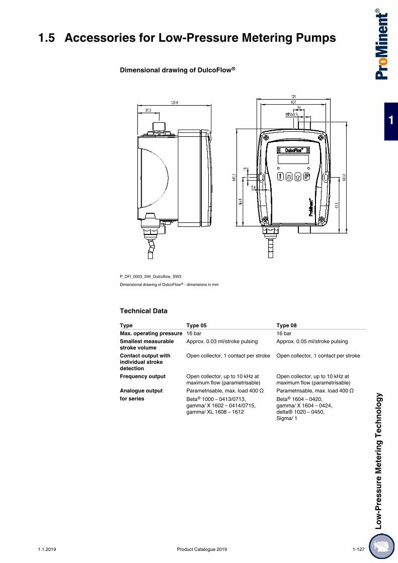
Low-
Pres
sure
Met
ering
Tech
nolog
y
1.5 Accessories for Low-Pressure Metering Pumps
1
Dimensional drawing of DulcoFlow®
P_DFl_0003_SW_Dulcoflow_SW3Dimensional drawing of DulcoFlow® - dimensions in mm
Technical DataType Type 05 Type 08Max. operating pressure 16 bar 16 barSmallest measurable stroke volume
Approx. 0.03 ml/stroke pulsing Approx. 0.05 ml/stroke pulsing
Contact output with individual stroke detection
Open collector, 1 contact per stroke Open collector, 1 contact per stroke
Frequency output Open collector, up to 10 kHz at maximum flow (parametrisable)
Open collector, up to 10 kHz at maximum flow (parametrisable)
Analogue output Parametrisable, max. load 400 Ω Parametrisable, max. load 400 Ωfor series Beta® 1000 – 0413/0713,
gamma/ X 1602 – 0414/0715, gamma/ XL 1608 – 1612
Beta® 1604 – 0420, gamma/ X 1604 – 0424, delta® 1020 – 0450,Sigma/ 1
1.1.2019 Product Catalogue 2019 1-127

1.5 Accessories for Low-Pressure Metering PumpsLo
w-Pr
essu
re M
eter
ing Te
chno
logy
1
Identity Code Ordering System for DulcoFlow® Ultrasound Flow MeterDFMa Type (for pump series)
05 Beta® 1000 – 0413/0713, gamma/ X 1602 – 0414/0715, gamma/XL 1608 – 161208 Beta® 1604 – 0420, gamma/ X 1604 – 0424, delta® 1020 – 0450, Sigma/ 1
Sealant materialE EPDMV FKMT PTFE
Hydraulic connection1 6/4 mm2 8/5 mm3 12/9 mm4 with G 3/4 external thread for DN 10 connector
Electrical connection, cableA 100 - 230 V AC, 2 m EuropeanB 100 - 230 V AC, 2 m SwissC 100 - 230 V AC, 2 m AustralianD 100 – 230 V AC, 2 m USA
Signal output0 No output1 Current output2 Contact output3 Current output and contact output4 Current output for delta® with control module
Version0 With ProMinent® logo
Accessories0 Without accessories
1-128 Product Catalogue 2019 1.1.2019

Low-
Pres
sure
Met
ering
Tech
nolog
y
1.5 Accessories for Low-Pressure Metering Pumps
1
Foot valves are fitted at the end of the suction line to prevent contamination and backflow.Foot valves include filter mesh and ball check – ceramic weight with connectors 6/4, 8/5, 12/6, 12/9.During installation, ensure that there is a sufficient gap between the foot valve and the pump foot and between the foot valve and the lowest suction water level.Union nuts and inserts/hose nozzles are included in the scope of delivery with DN 10 and DN 15 foot valve sizesImportant: Foot valves are not completely sealed shut-off devices!PPE Foot ValveHousing made of PP, seals made of EPDM.
PPE Foot ValveHousing made of PP, seals made of EPDM, with filter meshes and ball check (glass).
* PVDF/Teflon version
PPB Foot ValveHousing made of PP, seals made of FKM.
1.5.3 Hydraulic / Mechanical Installation Accessories
1.5.3.1 Foot Valves for Low-Pressure Metering Pumps
pk_1_038
Connector oØ x iØ A Fig. Order no.mm mm
6/4 for hose 6 x 4 84 pk_1_038 9245588/5 for hose 8 x 5 84 pk_1_038 80946812/9 for hose 12 x 9 87 pk_1_038 80947010/4 for hose 10 x 4 87 pk_1_038 100291612/6 for hose 12 x 6 87 pk_1_038 8094696/4 for hose 6 x 4 57 P_AC_0207_SW 914554
P_AC_0206_SW
DN 10, DN 15 with union nut and PP tube nozzleDN 20 to DN 40 no connection parts
G B Ø D2 A Ø D1 Order no. mm mm mm mm
DN 10 3/4 59 40 101 16 809465DN 15 1 66 47 142 20 924516DN 20 1 1/4 77 55 – – 803721DN 25 1 1/2 84 60 – – 803722DN 32* 2 98 74 – – 1006434DN 40 2 1/4 113 90 – – 1004204
Connector oØ x iØ A Fig. Order no.mm mm
6/4 for hose 6 x 4 84 pk_1_038 9245598/5 for hose 8 x 5 84 pk_1_038 92468312/9 for hose 12 x 9 87 pk_1_038 92468410/4 for hose 10 x 4 87 pk_1_038 100291512/6 for hose 12 x 6 87 pk_1_038 924685
1.1.2019 Product Catalogue 2019 1-129

1.5 Accessories for Low-Pressure Metering PumpsLo
w-Pr
essu
re M
eter
ing Te
chno
logy
1
PCB Foot ValveHousing made of PVC, seals made of FKM.
PCB Foot ValveHousing made of PP, seals made of FKM, with filter meshes and ball check (glass).
* PVDF/Teflon version
PVT Foot ValveHousing made of PVDF, seals made of PTFE.
P_AC_0207_SW
Connector oØ x iØ A Fig. Order no.mm mm
6/4 for hose 6 x 4 84 pk_1_038 9245578/5 for hose 8 x 5 84 pk_1_038 92456212/9 for hose 12 x 9 87 pk_1_038 92456410/4 for hose 10 x 4 87 pk_1_038 100291712/6 for hose 12 x 6 87 pk_1_038 9245636/4 for hose 6 x 4 57 P_AC_0207_SW 914505
P_AC_0206_SW
DN 10, DN 15 with union nut and PP tube nozzleDN 20 to DN 40 no connection parts
G B Ø D2 A Ø D1 Order no. mm mm mm mm
DN 10 3/4 59 40 101 16 809464DN 15 1 66 47 142 20 924515DN 20 1 1/4 77 55 – – 803723DN 25 1 1/2 84 60 – – 803724DN 32* 2 98 74 – – 1006434DN 40* 2 1/4 108 83 – – 1029475
pk_1_040
Connector oØ x iØ A Fig. Order no.mm mm
6/4 for hose 6 x 4 79 pk_1_040 10247058/5 for hose 8 x 5 79 pk_1_040 102470612/9 for hose 12 x 9 82 pk_1_040 1024707Universal, FDA-compliant 6 x 4 - 12 x 9 79 – 82 pk_1_040 1081422
1-130 Product Catalogue 2019 1.1.2019

Low-
Pres
sure
Met
ering
Tech
nolog
y
1.5 Accessories for Low-Pressure Metering Pumps
1
PVT Foot ValveHousing made of PVDF, ball seat made of PTFE + 25% carbon, PTFE seals, with filter mesh and ball check (ceramic DN 10 - 20, glass DN 25 - 40).
Foot valve PVT-FDA"Physiologically safe (FDA) in respect of wetted materials" design.All wetted materials in the "Physiologically safe (FDA) in respect of wetted materials" design comply with the FDA guidelines: Material PTFE: FDA No. 21 CFR § 177.1550 Material PVDF: FDA No. 21 CFR § 177.2510Housing made of PVDF, seals made of PTFE, with filter mesh and ball check (ceramic DN 10 - 20, glass DN 25).
Foot Valve TTTHousing made of PTFE, seals made of PTFE. With 6/4, 8/5, 12/6, 12/9 connectors with ceramic weight.
P_AC_0206_SW
DN 10, DN 15 with union nut and PP tube nozzleDN 20 to DN 40 no connection parts
G B Ø D2 A Ø D1 Order no. mm mm mm mm
DN 10 3/4 58 36 92 16 1029471DN 15 1 64 48 131 20 1029472DN 20 1 1/4 78 58 – – 1029473DN 25 1 1/2 81 65 – – 1029474DN 32 2 98 74 – – 1006434DN 40 2 1/4 108 83 – – 1029475
P_AC_0206_SW
DN 10, DN 15 with union nut and hose nozzleDN 20, DN 25 no connection parts
G B Ø D2 A Ø D1 Order no. mm mm mm mm
DN 10 3/4 58 36 92 16 1078269DN 15 1 64 48 131 20 1078270DN 20 1 1/4 78 58 – – 1078271DN 25 1 1/2 81 65 – – 1078272
pk_1_039
Connector oØ x iØ A Fig. Order no.mm mm
6/4 for hose 6 x 4 79 pk_1_040 8094558/5 for hose 8 x 5 79 pk_1_040 80947112/9 for hose 12 x 9 82 pk_1_040 80947312/6 for hose 12 x 6 82 pk_1_040 8094726/4 for hose 6 x 4 52 pk_1_039 914349
1.1.2019 Product Catalogue 2019 1-131
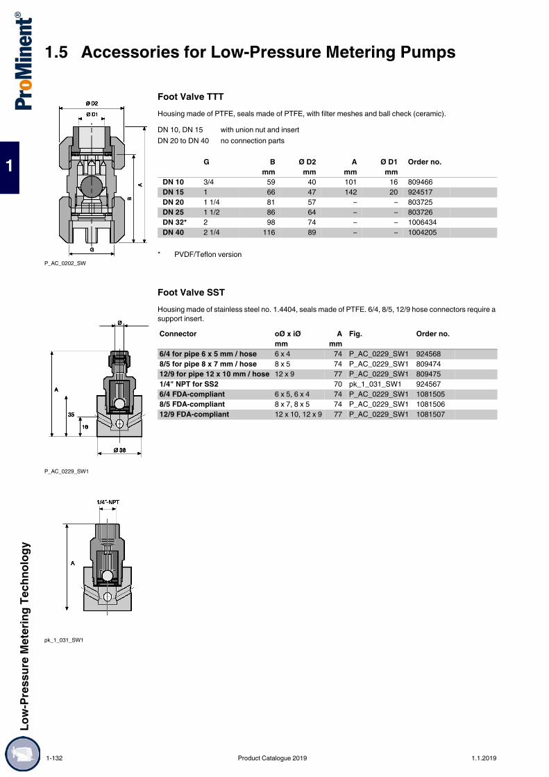
1.5 Accessories for Low-Pressure Metering PumpsLo
w-Pr
essu
re M
eter
ing Te
chno
logy
1
Foot Valve TTTHousing made of PTFE, seals made of PTFE, with filter meshes and ball check (ceramic).
Foot Valve SSTHousing made of stainless steel no. 1.4404, seals made of PTFE. 6/4, 8/5, 12/9 hose connectors require a support insert.
P_AC_0202_SW
DN 10, DN 15 with union nut and insertDN 20 to DN 40 no connection parts
G B Ø D2 A Ø D1 Order no. mm mm mm mm
DN 10 3/4 59 40 101 16 809466DN 15 1 66 47 142 20 924517DN 20 1 1/4 81 57 – – 803725DN 25 1 1/2 86 64 – – 803726DN 32* 2 98 74 – – 1006434DN 40 2 1/4 116 89 – – 1004205
* PVDF/Teflon version
P_AC_0229_SW1
pk_1_031_SW1
Connector oØ x iØ A Fig. Order no.mm mm
6/4 for pipe 6 x 5 mm / hose 6 x 4 74 P_AC_0229_SW1 9245688/5 for pipe 8 x 7 mm / hose 8 x 5 74 P_AC_0229_SW1 80947412/9 for pipe 12 x 10 mm / hose 12 x 9 77 P_AC_0229_SW1 8094751/4" NPT for SS2 70 pk_1_031_SW1 9245676/4 FDA-compliant 6 x 5, 6 x 4 74 P_AC_0229_SW1 10815058/5 FDA-compliant 8 x 7, 8 x 5 74 P_AC_0229_SW1 108150612/9 FDA-compliant 12 x 10, 12 x 9 77 P_AC_0229_SW1 1081507
1-132 Product Catalogue 2019 1.1.2019

Low-
Pres
sure
Met
ering
Tech
nolog
y
1.5 Accessories for Low-Pressure Metering Pumps
1
Foot Valve SSTHousing made of SS, PTFE + 25% ball seat, PTFE seals, with filter meshes and ball check (1.4571/1.4581).
Foot valve SST-FDA"Physiologically safe (FDA) in respect of wetted materials" designAll wetted materials in the "Physiologically safe (FDA) in respect of wetted materials" design comply with the FDA guidelines.FDA guidelines: Material PTFE: FDA No. 21 CFR § 177.1550 Material PVDF: FDA No. 21 CFR § 177.2510
Housing made of SS, PVDF ball seat, PTFE seals, with filter meshes and non-return valve (1/4571/1.4581).
P_AC_0204_SW
DN 10, DN 15 with union nut and insertDN 20 to DN 40 no connection parts
G A B Rp Ø D Order no. mm mm mm
DN 10 3/4 75 56 3/8 37 809467DN 15 1 83 59 1/2 48 924518DN 20 1 1/4 – 73 – 55 803727DN 25 1 1/2 – 82 – 63 803728DN 32 2 – 92 – 75 1006435DN 40 2 1/4 – 109 – 90 1004206
P_AC_0204_SW
DN 10, DN 15 with union nut and insertDN 20 to DN 40 no connection parts
G A B Rp Ø D Order no. mm mm mm
DN 10 3/4 75 56 3/8 37 1078275DN 15 1 83 59 1/2 48 1078289DN 20 1 1/4 – 73 – 55 1078290DN 25 1 1/2 – 82 – 63 1078291
1.1.2019 Product Catalogue 2019 1-133
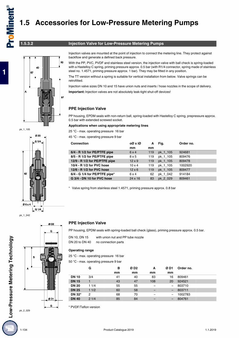
1.5 Accessories for Low-Pressure Metering PumpsLo
w-Pr
essu
re M
eter
ing Te
chno
logy
1
Injection valves are mounted at the point of injection to connect the metering line. They protect against backflow and generate a defined back pressure.With the PP, PVC, PVDF and stainless steel version, the injection valve with ball check is spring-loaded with a Hastelloy C spring, priming pressure approx. 0.5 bar (with R1/4 connector, spring made of stainless steel no. 1.4571, priming pressure approx. 1 bar). They may be fitted in any position.The TT version without a spring is suitable for vertical installation from below. Valve springs can be retrofitted.Injection valve sizes DN 10 and 15 have union nuts and inserts / hose nozzles in the scope of delivery.Important: Injection valves are not absolutely leak-tight shut-off devices!
PPE Injection ValvePP housing, EPDM seals with non-return ball, spring-loaded with Hastelloy C spring, prepressure approx. 0.5 bar with extended screwed socket.Applications when using appropriate metering lines25 °C - max. operating pressure 16 bar45 °C - max. operating pressure 9 bar
PPE Injection ValvePP housing, EPDM seals with spring-loaded ball check (glass), priming pressure approx. 0.5 bar.
Operating range25 °C - max. operating pressure 16 bar50 °C - max. operating pressure 9 bar
* PVDF/Teflon version
1.5.3.2 Injection Valve for Low-Pressure Metering Pumps
pk_1_105
pk_1_042
Connection oØ x iØ A Fig. Order no.mm mm
6/4 - R 1/2 for PE/PTFE pipe 6 x 4 119 pk_1_105 9246818/5 - R 1/2 for PE/PTFE pipe 8 x 5 119 pk_1_105 80947612/9 - R 1/2 for PE/PTFE pipe 12 x 9 119 pk_1_105 80947810/4 - R 1/2 for PVC hose 10 x 4 119 pk_1_105 100292012/6 - R 1/2 for PVC hose 12 x 6 119 pk_1_105 8094776/4 - G 1/4 for PE/PTFE pipe* 6 x 4 62 pk_1_042 914184G 3/4 - DN 10 for PVC hose 24 x 16 83 pk_2_029 809461
* Valve spring from stainless steel 1.4571, priming pressure approx. 0.8 bar
pk_2_029
DN 10, DN 15 with union nut and PP tube nozzleDN 20 to DN 40 no connection parts
G B Ø D2 A Ø D1 Order no. mm mm mm mm
DN 10 3/4 41 40 83 16 809461DN 15 1 43 47 108 20 924521DN 20 1 1/4 55 55 – – 803710DN 25 1 1/2 60 58 – – 803711DN 32* 2 68 70 – – 1002783DN 40 2 1/4 85 84 – – 804761
1-134 Product Catalogue 2019 1.1.2019

Low-
Pres
sure
Met
ering
Tech
nolog
y
1.5 Accessories for Low-Pressure Metering Pumps
1
PPB Injection ValvePP housing, FKM seals with spring-loaded non-return ball, prepressure approx. 0.5 bar.Applications when using appropriate metering lines25 °C - max. operating pressure 16 bar45 °C - max. operating pressure 9 bar
PP/PTFE Injection ValveFor prevention of chemical deposits. PP body, PTFE mounting insert, EPDM seals with ball check and Hastelloy C spring approx. 0.5 bar priming pressure (Fig. pk_1_046).Applications when using appropriate metering lines25 °C - max. operating pressure 16 bar45 °C - max. operating pressure 9 bar
PVC/PTFE Injection ValvePVC body, PTFE mounting insert, FKM-B seals, spring loaded ball check with Hastelloy C spring, approx. 0.5 bar priming pressure.Applications when using appropriate metering lines25 °C - max. operating pressure 16 bar45 °C - max. operating pressure 7 bar
pk_1_105
Connection oØ x iØ A Fig. Order no.mm mm
6/4 - R 1/2 for PE/PTFE pipe 6 x 4 119 pk_1_105 9246828/5 - R 1/2 for PE/PTFE pipe 8 x 5 119 pk_1_105 92468712/9 - R 1/2 for PE/PTFE pipe 12 x 9 119 pk_1_105 92468810/4 - R 1/2 for PVC hose 10 x 4 119 pk_1_105 100292112/6 - R 1/2 for PVC hose 12 x 6 119 pk_1_105 924689
pk_1_046
Connection oØ x iØ A Fig. Order no.mm mm
6/4 - R 1/2 for PE/PTFE pipe 6 x 4 103 pk_1_046 9245888/5 - R 1/2 for PE/PTFE pipe 8 x 5 103 pk_1_046 92458912/9 - R 1/2 for PE/PTFE pipe 12 x 9 106 pk_1_046 92459010/4 - R 1/2 for PVC hose 10 x 4 106 pk_1_046 100292312/6 - R 1/2 for PVC hose 12 x 6 106 pk_1_046 924591
Connector oØ x iØ Fig. Order no.mm
6/4 - R 1/2 for PE/PTFE pipe 6 x 4 pk_1_046 8094508/5 - R 1/2 for PE/PTFE pipe 8 x 5 pk_1_046 80945112/9 - R 1/2 for PE/PTFE pipe 12 x 9 pk_1_046 80945210/4 - R 1/2 for PVC hose 10 x 4 pk_1_046 100292412/6 - R 1/2 for PVC hose 12 x 6 pk_1_046 809453
1.1.2019 Product Catalogue 2019 1-135

1.5 Accessories for Low-Pressure Metering PumpsLo
w-Pr
essu
re M
eter
ing Te
chno
logy
1
PCB Injection ValvePVC housing, FKM seals, with Hastelloy C spring-loaded check ball, priming pressure approx. 0.5 bar, with extra-long screw-in fitting.Application when using appropriate metering line25 °C – max. operating pressure 25 bar for design 8/4 25 °C – max. operating pressure 16 bar45 °C – max. operating pressure 7 bar
PCB Injection ValvePVC housing, FKM seals with spring-loaded ball check (glass), priming pressure approx. 0.5 bar.
Operating range25 °C - max. operating pressure 16 bar45 °C - max. operating pressure 7 bar
* PVDF/Teflon version
PVT Injection ValvePVDF housing, PTFE seals, with Hastelloy C spring-loaded check ball, priming pressure approx. 0.5 bar, with extra-long screw-in fitting. 1.4571 spring with FDA-compliant design.Application when using appropriate metering line25 °C – max. operating pressure 25 bar for design 8/4 25 °C – max. operating pressure 20 bar for design 6/3 25 °C – max. operating pressure 16 bar45 °C – max. operating pressure 12 bar
pk_1_105
Connection oØ x iØ A Fig. Order no.mm mm
6/4 - R 1/2 for PE/PTFE pipe 6 x 4 119 pk_1_105 9246808/4 - R 1/2 for PTFE line 8 x 4 119 pk_1_105 10346218/5 - R 1/2 for PE/PTFE pipe 8 x 5 119 pk_1_105 92459212/9 - R 1/2 for PE/PTFE pipe 12 x 9 119 pk_1_105 92459410/4 - R 1/2 for PVC hose 10 x 4 119 pk_1_105 100291912/6 - R 1/2 for PVC hose 12 x 6 119 pk_1_105 9245936/4 - G 1/4 for PE/PTFE pipe* 6 x 4 62 – 914559
* Spring made of 1.4571, approx. 0.8 bar priming pressure.
pk_2_029
DN 10, DN 15 with union nut and PP tube nozzleDN 20 to DN 40 no connection parts
G B Ø D2 A Ø D1 Order no. mm mm mm mm
DN 10 3/4 41 40 83 16 809460DN 15 1 43 47 108 20 924520DN 20 1 1/4 55 55 – – 803712DN 25 1 1/2 60 58 – – 803713DN 32* 2 68 70 – – 1002783DN 40 2 1/4 85 84 – – 804760
pk_1_105
Connection oØ x iØ A Fig. Order no.mm mm
6/3 - R 1/2 for PTFE pipe 6 x 3 119 pk_1_105 10247136/4 - R 1/2 for PE/PTFE pipe 6 x 4 119 pk_1_105 10247088/4 - R 1/2 for PTFE line 8 x 4 119 pk_1_105 10346198/5 - R 1/2 for PE/PTFE pipe 8 x 5 119 pk_1_105 102471012/9 - R 1/2 for PE/PTFE pipe 12 x 9 119 pk_1_105 102471110/4 - R 1/2 for PVC hose 10 x 4 119 pk_1_105 102470912/6 - R 1/2 for PVC hose 12 x 6 119 pk_1_105 1024712Universal – R 1/2 FDA-compliant 6 x 4 - 12 x 9 119 pk_1_105 1081423
1-136 Product Catalogue 2019 1.1.2019

Low-
Pres
sure
Met
ering
Tech
nolog
y
1.5 Accessories for Low-Pressure Metering Pumps
1
Injection valve PVTPVDF housing, PTFE + 25% carbon ball seat, PTFE seals, with spring-loaded ball check (ceramic DN 10 - 20, glass DN 25 - 40), priming pressure approx. 0.5 bar.
Operating range25 °C - max. operating pressure 16 bar65 °C - max. operating pressure 10 bar
Injection valve PVT-FDA"Physiologically safe (FDA) in respect of wetted materials" design.All wetted materials in the "Physiologically safe (FDA) in respect of wetted materials" design comply with the FDA guidelines.FDA guidelines: Material PTFE: FDA-No. 21 CFR § 177.1550 Material PVDF: FDA-No. 21 CFR § 177.2510PVDF housing, PTFE seals, with spring-loaded ball check (ceramic), priming pressure approx. 0.5 bar.
Operating range25 °C - max. operating pressure 16 bar65 °C - max. operating pressure 10 bar
pk_2_029
DN 10, DN 15 with union nut and PP tube nozzleDN 20 to DN 40 no connection parts
G B Ø D2 A Ø D1 Order no. mm mm mm mm
DN 10 3/4 40 36 84 16 1029476DN 15 1 43 48 110 20 1029477DN 20 1 1/4 55 52 – – 1029478DN 25 1 1/2 61 56 – – 1029479DN 32 2 68 70 – – 1002783DN 40 2 1/4 85 81 – – 1029480
DN 10, DN 15 with union nut and PP tube nozzleDN 20 to DN 40 no connection parts
G B Ø D2 A Ø D1 Order no. mm mm mm mm
DN 10 3/4 40 36 84 16 1078237DN 15 1 43 48 110 20 1078238DN 20 1 1/4 55 52 – – 1078239DN 25 1 1/2 61 56 – – 1078240
1.1.2019 Product Catalogue 2019 1-137

1.5 Accessories for Low-Pressure Metering PumpsLo
w-Pr
essu
re M
eter
ing Te
chno
logy
1
PVT Injection Valve with Tantalum SpringInjection valve specially designed for metering sodium-calcium hypochlorite, with universal hose connector kit 6 x 4, 8 x 4, 8 x 5, 12 x 9, 10 x 4 and 12 x 6 mm.PVDF housing, PTFE seals, with tantalum spring-loaded check ball, priming pressure approx. 0.5 bar, with extra-long screw-in fitting.Application when using appropriate metering line25 °C – max. operating pressure 25 bar for design 8/425 °C – max. operating pressure 20 bar for design 6/325 °C – max. operating pressure 16 bar45 °C – max. operating pressure 12 bar
TTT Injection ValveVertical installation from below. With ball check, without spring. Valve spring (Order No. 469404) can be retrofitted. Body and seals made of PTFE.Applications when using appropriate metering lines25 °C - max. operating pressure 10 bar45 °C - max. operating pressure 5 bar
TTT Injection ValvePTFE housing and seals with spring-loaded ball check (ceramic, glass DN 25), priming pressure approx. 0.5 bar.
Operating range25 °C - max. operating pressure 10 bar90 °C - max. operating pressure 5 bar
Connection A Fig. Order no. mm
Universal connector, R 1/2 119 pk_1_105 1044653
P_AC_0184_SW
Connection oØ x iØ A Fig. Order no.mm
mm6/4 - R 1/2 for PE/PTFE pipe 6 x 4 98 P_AC_0184_SW 8094888/5 - R 1/2 for PE/PTFE pipe 8 x 5 98 P_AC_0184_SW 80947912/9 - R 1/2 for PE/PTFE pipe 12 x 9 101 P_AC_0184_SW 80948112/6 - R 1/2 for PVC hose 12 x 6 101 P_AC_0184_SW 809480
pk_2_030
DN 10, DN 15 with union nut and insertDN 20 to DN 40 no connection parts
G B Ø D2 A Ø D1 Order no. mm mm mm mm
DN 10 3/4 38 36 57 16 809462DN 15 1 43 48 63 20 924522DN 20 1 1/4 55 50 – – 803714DN 25 1 1/2 60 58 – – 803715DN 32* 2 68 70 – – 1002783DN 40 2 1/4 85 84 – – 804762
* PVDF/Teflon version
1-138 Product Catalogue 2019 1.1.2019

Low-
Pres
sure
Met
ering
Tech
nolog
y
1.5 Accessories for Low-Pressure Metering Pumps
1
SST Injection ValveHousing made of stainless steel no. 1.4404, PTFE seals, with Hastelloy C spring-loaded check ball, priming pressure approx. 0.5 bar, with R 1/4 spring made of stainless steel no. 1.4571, priming pressure approx. 1 bar. A support insert is required to connect PE / PTFE lines. 1.4571 spring with FDA-compliant design.Applications when using appropriate metering lines25 °C - max. operating pressure 30 bar45 °C - max. operating pressure 30 bar
SST Injection ValveHousing made of stainless steel, PTFE + 25% carbon ball seat, PTFE seals non-return sphere (stainless steel material no. 1.4571 / stainless steel no. 1.4581) spring-loaded, priming pressure approx. 0.5 bar.
Applications90 °C - max. operating pressure, see table
Injection valve SST - FDA"Physiologically safe (FDA) in respect of wetted materials" design. All wetted materials in the "Physiologically safe (FDA) in respect of wetted materials" design comply with the FDA guidelines.FDA guidelines: Material PTFE: FDA No. 21 CFR § 177.1550 Material PVDF: FDA No. 21 CFR § 177.2510Housing made of stainless steel, PVDF ball seat, PTFE seals with non-return sphere (stainless steel material no. 1.4571 / stainless steel no. 1.4581) spring-loaded, priming pressure approx. 0.5 bar.
Applications90 °C - max. operating pressure, see table
pk_1_032_1
pk_1_032_2
P_AC_0253_SWpk_2_030
Connection oØ x iØ A Fig. Order no.mm mm
6 mm - R 1/2 for pipe 6 x 5 93 pk_1_032_1 8094898 mm - R 1/2 for pipe 8 x 7 93 pk_1_032_1 80948212 mm - R 1/2 for pipe 12 x 10 96 pk_1_032_1 8094831/4" NPT - R 1/2 for pipe R 1/4" NPT 89 pk_1_032_2 9245976 mm - R 1/4 for pipe – P_AC_0253_SW 9145886 mm - R 1/2 for pipe, FDA-compliant 6 x 5 93 pk_1_032_1 10814828 mm - R 1/2 for pipe, FDA-compliant 8 x 7 93 pk_1_032_1 108148312 mm - R 1/2 for pipe, FDA-compliant 12 x 10 96 pk_1_032_1 1081504
pk_2_030
DN 10, DN 15 with union nut and insertDN 20 to DN 40 no connection parts
G Max. pressure B Ø D2 A Ø D1 Order no. bar mm mm mm
DN 10 3/4 320 38 36 55 3/8 809463DN 15 1 240 43 48 63 1/2 924523DN 20 1 1/4 130 55 55 – – 803716DN 25 1 1/2 70 60 58 – – 803717DN 32 2 45 69 68 – – 1002801DN 40 2 1/4 25 85 84 – – 804763
pk_2_030
DN 10, DN 15 with union nut and insertDN 20 to DN 40 no connection parts
G Max. pressure B Ø D2 A Ø D1 Order no. bar mm mm mm
DN 10 3/4 320 38 36 55 3/8 1078251DN 15 1 240 43 48 63 1/2 1078252DN 20 1 1/4 130 55 55 – 1078266DN 25 1 1/2 70 60 58 – 1078267
1.1.2019 Product Catalogue 2019 1-139

1.5 Accessories for Low-Pressure Metering PumpsLo
w-Pr
essu
re M
eter
ing Te
chno
logy
1
PPB Injection Valve O-Ring LoadedPP body, FKM seals. Priming pressure approx. 0.5 bar.Applications when using appropriate metering lines25 °C - max. operating pressure 16 bar45 °C - max. operating pressure 9 bar
PCB Injection Valve O-Ring LoadedPVC body, FKM seals, priming pressure approx. 0.5 bar.Applications when using appropriate metering lines25 °C - max. operating pressure 16 bar45 °C - max. operating pressure 7 bar
PTFE Injection Valve O-Ring LoadedPTFE housing, FKM seals.Applications when using appropriate metering lines25 °C - max. operating pressure 10 bar45 °C - max. operating pressure 6 bar
P_AC_0008_SW
Connector oØ x iØ Fig. Order no.mm
6/4 - G 1/4 short 6 x 4 P_AC_0008_SW 9147546/4 - G 1/4 long 6 x 4 P_AC_0009_SW 741193
P_AC_0009_SW
Connector oØ x iØ Fig. Order no.mm
6/4 - G 1/4 short 6 x 4 P_AC_0008_SW 9145586/4 - G 1/4 long 6 x 4 P_AC_0009_SW 915091
P_AC_0183_SW
Connection oØ x iØ A Fig. Order no.mm mm
6/4 – for PE/PTFE line 6 x 4 104 P_AC_0183_SW 8094848/5 – for PE/PTFE line 8 x 5 104 P_AC_0183_SW 80948510/4 – for PVC hose 10 x 4 104 P_AC_0183_SW 100292512/6 – for PVC hose 12 x 6 104 P_AC_0183_SW 80948712/9 – for PE/PTFE line 12 x 9 104 P_AC_0183_SW 809486
1-140 Product Catalogue 2019 1.1.2019

Low-
Pres
sure
Met
ering
Tech
nolog
y
1.5 Accessories for Low-Pressure Metering Pumps
1
Lip Seal Injection Valve PCBBody PVC, seals FKM, inlet pressure approx. 0.05 bar. For metering sodium hypochlorite and for use in conjunction with the peristaltic pump DF2a.Applications when using appropriate metering lines25 °C - max. operating pressure 2 bar45 °C - max. operating pressure 2 bar
Metering Connector for Warm Water up to 200 °CConsists of stainless steel 1.4404 injection valve, 1 m stainless steel 1.4571 discharge line and threaded connector with reinforcing sleeve for connection of PE/PTFE pipe to stainless steel pipe.Max. operating pressure 30 bar
PVDF Metering Valve AdapterFor the installation of injection valves into pipework with straight unions.The adapter projects into the pipework or storage tanks and can be adjusted (shortened) at different cross-sections.Direct contact of the chemical to be metered with the wall can be avoided by installation of the adapter. Metering into the centre of the pipework improves, among other things, the mixing through of the metering solution.Material: PVDFApplications25 °C - max. operating pressure 16 bar65 °C - max. operating pressure 10 bar
D = Width across flats* In set with 1 x FKM and 1 x EPDM O-ring.
pk_1_070
Connection oØ x iØ A Fig. Order no.mm mm
6/4 - R 1/2 - 1/4 for PE/PTFE pipe 6 x 4 90 pk_1_070 101995310/4 - R 1/2 - 1/4 for PE/PTFE pipe 10 x 4 90 pk_1_070 1024697
pk_1_049
Connection Fig. Order no.Warm water 6 mm - R 1/4 pk_1_049 913166Warm water 6 mm - R 1/2 pk_1_049 913167Warm water 8 mm - R 1/2 pk_1_049 913177Warm water 12 mm - R 1/2 pk_1_049 913188
P_AC_0275_SW
E1 E2 A B C D Ø D1 Ø D2 Order no. mm mm mm mm mm mm
Rp 3/4 R 3/4 93 63 49,000 32 22 15 1022052Rp 1 R 1 95 65 50,000 41 27 18 1022053G 1 1/4 G 1 1/4 A* 150 119 104,000 50 27 18 1040722G 1 1/2 G 1 1/2 A* 171 135 118,000 60 31 20 1040723
1.1.2019 Product Catalogue 2019 1-141

1.5 Accessories for Low-Pressure Metering PumpsLo
w-Pr
essu
re M
eter
ing Te
chno
logy
1
PPE Injection LanceFor immersion depths of 20 - 165 mm, in large diameter pipe to prevent chemical deposition at the point of injection. Consists of spring-loaded metering valve, Hastelloy C spring, ceramic ball, adjustable immersion rod and hose valve. With connectors for all hose sizes used with solenoid-driven metering pumps: 6/4, 8/5, 12/9, 10/4 and 12/6.
* Please note: The product contains connections bonded with Tangit. Always note the durability of Tangit adhesive.
Short Injection LanceMetering lance with universal connection kit, enabling the connection of different hose sizes of from 6/4 to 12/9. Hastelloy C spring, ceramic ball and silicone hose. Material of screwed socket: PVDF.
PVDF Non-Return Valve for Hose InstallationWith connection kit on both sides for fitting in hose line.With non-return ball, spring-loaded with Hastelloy C spring, prepressure approx. 0.5 bar.PVDF housing, PTFE seals.Different hose sizes from 6/4 to 12/9 can be joined using different connection kits.Applications when using appropriate metering lines25 °C - max. operating pressure 16 bar45 °C - max. operating pressure 12 bar
1.5.3.3 Injection Lances, Non-Return Valves for Low-Pressure Metering Pumps
pk_1_007
pk_1_062
Type Seal material Max. pressureat 25 °C
Fig. Order no.
barPPE without stopcock EPDM/silicone 6 pk_1_062 1021530PPE with stopcock EPDM/silicone 6 pk_1_007 1021531PCB without stopcock FKM/silicone* 6 pk_1_062 1021528PCB with stopcock FKM/silicone* 6 pk_1_007 1021529
P_AC_0020_SW
Type Material, valve body
Max. pressureat 25 °C
Seals A Fig. Order no.
bar mmPPE PP 16 EPDM 126 P_AC_0020_SW 1028383PCB PVC 16 FKM-B 126 P_AC_0020_SW 1028363PVT PVDF 16 PTFE 126 P_AC_0020_SW 1028081
P_AC_0181_SW
Connection oØ x iØ A Fig. Order no.mm mm
6/4 for PE/PTFE line 6 x 4 67 P_AC_0181_SW 10304638/5 for PE/PTFE line 8 x 5 67 P_AC_0181_SW 103097510/4 for PE/PTFE line 10 x 4 67 P_AC_0181_SW 103097712/6 for PVC hose 12 x 6 67 P_AC_0181_SW 103097812/9 for PE/PTFE line 12 x 9 67 P_AC_0181_SW 1030976
1-142 Product Catalogue 2019 1.1.2019

Low-
Pres
sure
Met
ering
Tech
nolog
y
1.5 Accessories for Low-Pressure Metering Pumps
1
Back pressure valves are used to generate a constant back pressure to ensure precise metering and protect against over-metering or metering imprecision through a free outlet and priming pressure on the suction side. They are also used in conjunction with pulsation dampers to generate low-pulsation metering. We recommend back pressure valves type DHV-U with fluctuating back pressure.(Back Pressure Valves / Relief Valves for Motor-Driven Metering Pumps see volume "Motor-driven and process metering pumps for all capacity ranges" page )The DHV listed below are designed for different applications. Please note the relevant notes for the different mountings.
Relief valves are used to protect pumps, pipes and fittings from over pressure, in the event of incorrect operation or blockages in the bypass. In the event of a malfunction, the pump pumps back into the storage tank.Multifunctional Valve Type MFV-DK, PVDFBack pressure valve / relief valve for fitting directly on the pump's dosing head with the functions: Back pressure valve, opening pressure approx. 1.5 bar with free outlet or priming pressure at the suction
end (black rotary dial) Relief valve, opening pressure approx. 6, 10 or 16 bar (red rotary dial) Priming aid for pending back pressure, no need to release discharge line Discharge line relief, e.g. prior to service workThe multifunctional valve is operated by free-moving rotary dials that automatically return to their original position when released by the operator. This means operation is possible even when access is difficult. The multifunctional valve is made of PVDF and can be used to meter almost any chemical.Caution: Back pressure valves are not absolutely leak-tight shut-off devices! It is essential that you observe the installation notes in the operating instructions!Caution: The bypass line should always be connected.For hoses see page → 1-157.
Application: multifunctional valves
For material version PP, PV, NP, TT
1.5.3.4 Back Pressure Valves / Relief Valves for Low-Pressure Metering Pumps
Important: Back pressure valves cannot be used as absolutely leak-tight shut-off devices. Take appropriate precautions when handling hazardous media.
pk_1_053
Valve body PVDFDiaphragm PTFE- coatedSeal FKM and EPDM (enclosed)
Type Relief opening pressure* Connection Bypass connector Order no.Size I 16 bar 6-12 6 x 4 792011Size I 10 bar 6-12 6 x 4 791715Size I 6 bar 6-12 6 x 4 1005745Size II 10 bar 6-12 12 x 9 792203Size II 6 bar 6-12 12 x 9 740427Size III 10 bar DN 10 12 x 9 792215
* The relief opening pressure given above is the pressure at which the valve begins to open. The pressure can be up to 50% higher until the valve is fully open depending on the type of pump.
Size I ALPc 1001, 1002, 1004, 1008, 0708Beta®, type 1000, 1601, 1602, 1604, 1605, 1005, 1008, 0708, 0413, 0220gamma/ X type 1602, 1604, 1009, 0708, 0414, 0220gamma/ XL type 1608, 1612
Size II ALPc 0417, 0230Beta®, type 1605, 1008, 0713, 0420, 0232gamma/ X type 1009, 0715, 0424, 0245gamma/XL type 1020, 0730
Size III gamma/ XL type 0450, 0280
1.1.2019 Product Catalogue 2019 1-143
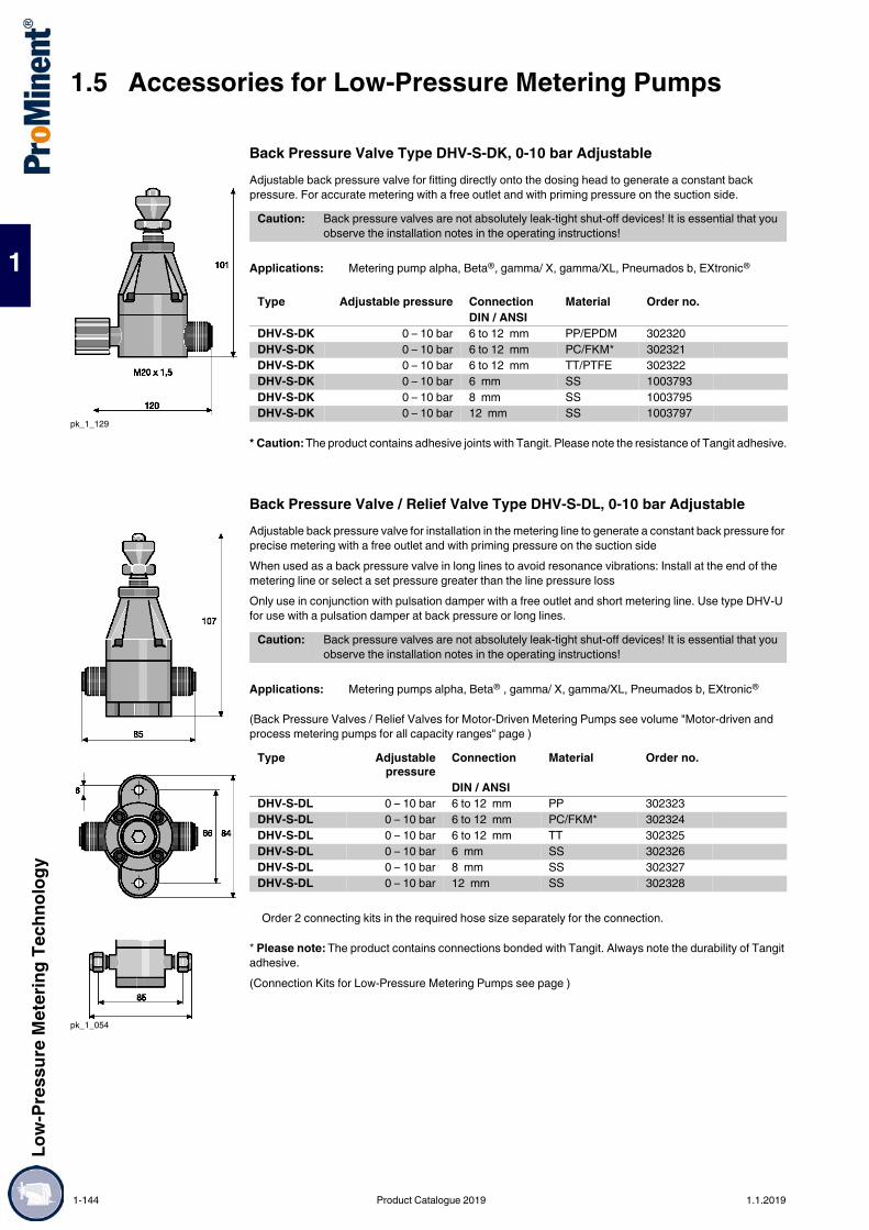
1.5 Accessories for Low-Pressure Metering PumpsLo
w-Pr
essu
re M
eter
ing Te
chno
logy
1
Back Pressure Valve Type DHV-S-DK, 0-10 bar AdjustableAdjustable back pressure valve for fitting directly onto the dosing head to generate a constant back pressure. For accurate metering with a free outlet and with priming pressure on the suction side.
* Caution: The product contains adhesive joints with Tangit. Please note the resistance of Tangit adhesive.
Back Pressure Valve / Relief Valve Type DHV-S-DL, 0-10 bar AdjustableAdjustable back pressure valve for installation in the metering line to generate a constant back pressure for precise metering with a free outlet and with priming pressure on the suction sideWhen used as a back pressure valve in long lines to avoid resonance vibrations: Install at the end of the metering line or select a set pressure greater than the line pressure lossOnly use in conjunction with pulsation damper with a free outlet and short metering line. Use type DHV-U for use with a pulsation damper at back pressure or long lines.
(Back Pressure Valves / Relief Valves for Motor-Driven Metering Pumps see volume "Motor-driven and process metering pumps for all capacity ranges" page )
* Please note: The product contains connections bonded with Tangit. Always note the durability of Tangit adhesive.(Connection Kits for Low-Pressure Metering Pumps see page )
pk_1_129
Caution: Back pressure valves are not absolutely leak-tight shut-off devices! It is essential that you observe the installation notes in the operating instructions!
Applications: Metering pump alpha, Beta®, gamma/ X, gamma/XL, Pneumados b, EXtronic®
Type Adjustable pressure Connection Material Order no.DIN / ANSI
DHV-S-DK 0 – 10 bar 6 to 12 mm PP/EPDM 302320DHV-S-DK 0 – 10 bar 6 to 12 mm PC/FKM* 302321DHV-S-DK 0 – 10 bar 6 to 12 mm TT/PTFE 302322DHV-S-DK 0 – 10 bar 6 mm SS 1003793DHV-S-DK 0 – 10 bar 8 mm SS 1003795DHV-S-DK 0 – 10 bar 12 mm SS 1003797
pk_1_054
Caution: Back pressure valves are not absolutely leak-tight shut-off devices! It is essential that you observe the installation notes in the operating instructions!
Applications: Metering pumps alpha, Beta® , gamma/ X, gamma/XL, Pneumados b, EXtronic®
Type Adjustablepressure
Connection Material Order no.
DIN / ANSIDHV-S-DL 0 – 10 bar 6 to 12 mm PP 302323DHV-S-DL 0 – 10 bar 6 to 12 mm PC/FKM* 302324DHV-S-DL 0 – 10 bar 6 to 12 mm TT 302325DHV-S-DL 0 – 10 bar 6 mm SS 302326DHV-S-DL 0 – 10 bar 8 mm SS 302327DHV-S-DL 0 – 10 bar 12 mm SS 302328
Order 2 connecting kits in the required hose size separately for the connection.
1-144 Product Catalogue 2019 1.1.2019

Low-
Pres
sure
Met
ering
Tech
nolog
y
1.5 Accessories for Low-Pressure Metering Pumps
1
Pipe NipplesFor the direct connection of the pressure maintenance valve DHV-S-DL in stainless steel (SS) to the liquid end.
Back Pressure Valve / Relief Valve Type DHV-UUniversal back pressure valves of the DHV-U product range are back pressure-free plunger diaphragm valves with an internal flow. They are used to generate a constant back pressure and also as relief valves. They can be installed at any location in the pipework system.Back pressure valves are used to generate a constant back pressure for precise pumping and to protect against over-metering where there is a free outlet or fluctuating back pressure or priming pressure on the suction side. They are also used in conjunction with pulsation dampers to generate low-pulsation metering.Relief valves are used to protect pumps, pipes and fittings from overpressure, in the event of incorrect operation or blockages in the bypass. In the event of a malfunction, the pump pumps around the circuit or back into the storage tank.Important:Back pressure valves cannot be used as absolutely leak-tight shut-off devices. Take appropriate safety precautions when handling hazardous media. Relief valves are not safety valves by their definition as per DIN EN ISO 4126-1.Important:Take appropriate safety measures (e.g. flushing after possible response) when using as relief valves in conjunction with viscous media (e.g. lime milk).
Application of PPE/PPB/PCE/PCB:20 °C - max. operating pressure 10 barApplication of PVT/SST:30 °C - max. operating pressure 10 bar
pk_1_017
Type A B Fig. Order no. mm mm
1.4571 pipe nipple 6 40 pk_1_017 8185378 40 pk_1_017 818538
12 40 pk_1_017 818539
Adjustable pressure 0.5 – 10 bar
P_AC_0256_SW
Type Nominal diameter G Order no.PPE DN 10 3/4 1037285PPB DN 10 3/4 1038133PCE DN 10 3/4 1038144PCB DN 10 3/4 1037765PVT DN 10 3/4 1037767SST DN 10 3/4 1043194PPE DN 15 1 1036816PPB DN 15 1 1038145PCE DN 15 1 1038146PCB DN 15 1 1037764PVT DN 15 1 1037766SST DN 15 1 1043193PPE DN 20 1 1/4 1037284PPB DN 20 1 1/4 1038147PCE DN 20 1 1/4 1038148PCB DN 20 1 1/4 1037775PVT DN 20 1 1/4 1037777SST DN 20 1 1/4 1043192PPE DN 25 1 1/2 1036633PPB DN 25 1 1/2 1038149PCE DN 25 1 1/2 1038150PCB DN 25 1 1/2 1037774PVT DN 25 1 1/2 1037776SST DN 25 1 1/2 1043191PPE DN 32 2 1051517PPB DN 32 2 1051522PCE DN 32 2 1051514
1.1.2019 Product Catalogue 2019 1-145

1.5 Accessories for Low-Pressure Metering PumpsLo
w-Pr
essu
re M
eter
ing Te
chno
logy
1
Materials
* Cover ring made of PTFE/FKMFDA design (21CFR177...)We are happy to supply physiologically harmless (FDA) material designs of wetted materials for PPE, PVT and SST.Dimensions of DHV-U (PP, PVC, PVDF design)
Dimensions of DHV-U (SS version)
PCB DN 32 2 1051520PVT DN 32 2 1051503SST DN 32 2 1051516PPE DN 40 2 1/4 1051518PPB DN 40 2 1/4 1051521PCE DN 40 2 1/4 1051501PCB DN 40 2 1/4 1051519PVT DN 40 2 1/4 1051502SST DN 40 2 1/4 1051515
Type Housing/Connectors Plungers Plunger Seal Seal/ConnectorsPPE PP PVDF EPDM EPDMPPB PP PVDF FKM FKMPCE PVC PVDF EPDM EPDMPCB PVC PVDF FKM FKMPVT PVDF PVDF PTFE* FKMSST 1.4404 PTFE PTFE* PTFE
Type Nominal diameter G Order no.
P_AC_0256_m
P_MOZ_0005_SW
DN G H L h D m Bmm mm mm mm mm
10 3/4 144* 118 24 79 M6 4015 1 144* 118 24 79 M8 4020 1 1/4 196* 150 37 99 M8 4625 1 1/2 196* 150 37 99 M6 4632 2 252 200 54 139.5 M8 6540 2 1/4 252 200 54 139.5 M8 65
* Approximate values
DN G H L h D m Bmm mm mm mm mm
10 3/4 144* 118 20 79 M6 4015 1 144* 118 20 79 M6 4020 1 1/4 196* 150 30 99 M6 4625 1 1/2 196* 150 30 99 M6 4632 2 252 200 37 139.5 M8 6540 2 1/4 252 200 37 139.5 M8 65
* Approximate values
1-146 Product Catalogue 2019 1.1.2019

Low-
Pres
sure
Met
ering
Tech
nolog
y
1.5 Accessories for Low-Pressure Metering Pumps
1
Back Pressure Valve / Relief Valve Type DHV-U in physiologically safe design (FDA)Back pressure valves for motor-driven metering pumps are designed for different applications. Please refer to the relevant notes for the different designs.Relief valves are used in the bypass to protect pumps, pipes and fittings from overpressure in the event of incorrect operation or blockages. In the event of a malfunction, the pump pumps back into the storage tank.
Application of PPE/PPB/PCE/PCB20 °C - max. operating pressure 10 barApplication of PVT/SST30 °C - max. operating pressure 10 bar
Materials
* Cover ring made of PTFE/FKMAll wetted materials in the "Physiologically safe (FDA) in respect of wetted materials" design comply with the following FDA guidelines:
Adjustable pressure 0.5 – 10 bar
P_AC_0256_SW
Type Nominal diameter G Order no.PPE DN 10 3/4 1076578PVT DN 10 3/4 1076579SST DN 10 3/4 1076532PPE DN 15 1 1076580PVT DN 15 1 1076581SST DN 15 1 1076531PPE DN 20 1 1/4 1076582PVT DN 20 1 1/4 1076583SST DN 20 1 1/4 1076597PPE DN 25 1 1/2 1076585PVT DN 25 1 1/2 1076586SST DN 25 1 1/2 1076584PPE DN 32 2 1076587PVT DN 32 2 1076588SST DN 32 2 1076589PPE DN 40 2 1/4 1076590PVT DN 40 2 1/4 1076591SST DN 40 2 1/4 1076592
Type Housing/Connectors Plungers Plunger Seal Seal/ConnectorsPPE PP PVDF EPDM EPDMPVT PVDF PVDF PTFE* FKMSST 1.4404 PTFE PTFE* PTFE
Material GuidelinePTFE 21CFR177.1510PVDF 21CFR177.2510PP 21CFR177.1520EPDM/FKM 21CFR177.2600
1.1.2019 Product Catalogue 2019 1-147

1.5 Accessories for Low-Pressure Metering PumpsLo
w-Pr
essu
re M
eter
ing Te
chno
logy
1
Dimensions of DHV-U (FDA) (PP, PVC, PVDF design)
Dimensions of DHV-U (FDA) (SS design)P_AC_0256_m
P_MOZ_0005_SW
DN G H L h D m Bmm mm mm mm mm
10 3/4 144* 118 24 79 M6 4015 1 144* 118 24 79 M6 4020 1 1/4 196* 150 37 99 M6 4625 1 1/2 196* 150 37 99 M6 4632 2 252* 200 54 139.5 M8 6540 2 1/4 252* 200 54 139.5 M8 65
* Approximate values
DN G H L h D m Bmm mm mm mm mm
10 3/4 144* 118 20 79 M6 4015 1 144* 118 20 79 M6 4020 1 1/4 196* 150 30 99 M6 4625 1 1/2 196* 150 30 99 M6 4632 2 252* 200 37 139.5 M8 6540 2 1/4 252* 200 37 139.5 M8 65
* Approximate values
1-148 Product Catalogue 2019 1.1.2019

Low-
Pres
sure
Met
ering
Tech
nolog
y
1.5 Accessories for Low-Pressure Metering Pumps
1
Relief valve type DHV-URThe universal relief valves type DHV-UR are, like all valves in the DHV-U product range, are continuously adjustable plunger diaphragm valves with an internal flow. In the event of impermissible overpressure, the internal plunger diaphragm opens the second output power, the bleeder output. Can be installed at any location in the pipework system. Very low pressure losses when the relief valve is closed owing to its virtually free pipe cross-section Simple spare parts management, the wear parts (pressure spring, diaphragms, plunger seal, connector set seal) correspond to the DHV-U valve product range.
Application of PPE/PPB/PCE/PCB20 °C - max. operating pressure 10 barApplication of PVT/SST30 °C - max. operating pressure 10 bar
Materials used
* Cover ring made of PTFE/FKMFDA design (21CFR177...)We are happy to supply physiologically harmless (FDA) material designs of wetted materials for PPE, PVT and SST.
P_AC_0267
P_AC_0268
AP_0003
1 3
2
1 Input2 Bleeder output3 Output
1 3
2
1 Input2 Bleeder output3 Output
Adjustable pressure 0.5 – 10 bar
Type Nominal diameter G Order no.PPE DN 10 3/4 1061337PPB DN 10 3/4 1061341PCE DN 10 3/4 1061339PCB DN 10 3/4 1061343PVT DN 10 3/4 1061365SST DN 10 3/4 1061550PPE DN 15 1 1061336PPB DN 15 1 1061340PCE DN 15 1 1061338PCB DN 15 1 1061342PVT DN 15 1 1061364SST DN 15 1 1061551PPE DN 20 1 1/4 1061367PPB DN 20 1 1/4 1061371PCE DN 20 1 1/4 1061369PCB DN 20 1 1/4 1061373PVT DN 20 1 1/4 1061375SST DN 20 1 1/4 1061569PPE DN 25 1 1/2 1061366PPB DN 25 1 1/2 1061370PCE DN 25 1 1/2 1061368PCB DN 25 1 1/2 1061372PVT DN 25 1 1/2 1061374SST DN 25 1 1/2 1061570
Type Housing/Connectors Plungers Plunger Seal Seal/ConnectorsPPE PP PVDF EPDM EPDMPPB PP PVDF FKM FKMPCE PVC PVDF EPDM EPDMPCB PVC PVDF FKM FKMPVT PVDF PVDF PTFE* FKMSST 1.4404 1.4404 PTFE* PTFE
1.1.2019 Product Catalogue 2019 1-149

1.5 Accessories for Low-Pressure Metering PumpsLo
w-Pr
essu
re M
eter
ing Te
chno
logy
1
Dimensions of DHV-UR (PP, PVC, PVDF design)
Dimensions of DHV-UR (SS design)
Relief valve type DHV-UR, FDA designBack pressure valves for motor-driven metering pumps are designed for different applications. Please refer to the relevant notes for the different designs.Relief valves are used in the bypass to protect pumps, pipes and fittings from overpressure in the event of incorrect operation or blockages. In the event of a malfunction, the pump pumps back into the storage tank.
Application of PPE/PPB/PCE/PCB20 °C - max. operating pressure 10 barApplication of PVT/SST30 °C - max. operating pressure 10 bar
All wetted materials in the "Physiologically safe (FDA) in respect of wetted materials" design comply with the following FDA guidelines:
P_AC_0267_V2
P_AC_0268_V2
H
D
L
DN G
h
DN G H L h D m Bmm mm mm mm mm
10 3/4 144* 118 24 79 M6 3515 1 144* 118 24 79 M6 3520 1 1/4 196* 150 37 99 M6 4625 1 1/2 196* 150 37 99 M6 46
* Approximate values
DN G H L h D m Bmm mm mm mm mm
10 3/4 144* 118 20 79 M6 3515 1 144* 118 20 79 M6 3520 1 1/4 196* 150 30 99 M6 4625 1 1/2 196* 150 30 99 M6 46
* Approximate values
P_AC_0267
P_AC_0268_V3
Adjustable pressure 0.5 – 10 bar
Type Nominal diameter G Order no.PPE DN 10 3/4 1075828PVT DN 10 3/4 1075830SST DN 10 3/4 1075847PPE DN 15 1 1075827PVT DN 15 1 1075829SST DN 15 1 1075846PPE DN 20 1 1/4 1075833PVT DN 20 1 1/4 1075845SST DN 20 1 1/4 1075849PPE DN 25 1 1/2 1075832PVT DN 25 1 1/2 1075844SST DN 25 1 1/2 1075848
Material GuidelinePTFE 21CFR177.1510PVDF 21CFR177.2510PP 21CFR177.1520EPDM/FKM 21CFR177.2600
1-150 Product Catalogue 2019 1.1.2019

Low-
Pres
sure
Met
ering
Tech
nolog
y
1.5 Accessories for Low-Pressure Metering Pumps
1
Materials used
* Cover ring made of PTFE/FKMDimensions of DHV-UR (FDA) (PP, PVC, PVDF design)
Dimensions of DHV-UR (FDA) (SS design)
Type Housing/Connectors Plungers Plunger Seal Seal/ConnectorsPPE PP PVDF EPDM EPDMPVT PVDF PVDF PTFE* FKMSST 1.4404 1.4404 PTFE* PTFE
P_AC_0267_V2
P_AC_0268_V2
H
D
L
DN G
h
DN G H L h D m Bmm mm mm mm mm
10 3/4 144* 118 24 79 M6 3515 1 144* 118 24 79 M6 3520 1 1/4 196* 150 37 99 M6 4625 1 1/2 196* 150 37 99 M6 46
* Approximate values
DN G H L h D m Bmm mm mm mm mm
10 3/4 144* 118 20 79 M6 3515 1 144* 118 20 79 M6 3520 1 1/4 196* 150 30 99 M6 4625 1 1/2 196* 150 30 99 M6 46
* Approximate values
1.1.2019 Product Catalogue 2019 1-151

1.5 Accessories for Low-Pressure Metering PumpsLo
w-Pr
essu
re M
eter
ing Te
chno
logy
1
Relief valve type DHV-UR M configured for manometerThe relief valves DHV-UR with M designs are configured with a plug for manometer installation. Manometer with threaded socket G 1/4“ (ISO 228) can be fitted by the customer directly to the relief valve via the additional housing opening. Standard manometers with part number are available for neutral media. This also enables savings in terms of installation.
Application of PPE/PPB/PCE/PCB:20 °C - max. operating pressure 10 barApplication of PVT/SST:30 °C - max. operating pressure 10 bar
Materials used
* Cover ring made of PTFE/FKM
P_AC_0272
P_AC_0271_V21: Plug for manometer installation
1
Adjustable pressure 0.5 – 10 bar
Type Nominal diameter G Order no.PPE DN 10 3/4 1077221PPB DN 10 3/4 1077259PCE DN 10 3/4 1077255PCB DN 10 3/4 1077263PVT DN 10 3/4 1077267PPE DN 15 1 1077220PPB DN 15 1 1077258PCE DN 15 1 1077254PCB DN 15 1 1077262PVT DN 15 1 1077266PPE DN 20 1 1/4 1077219PPB DN 20 1 1/4 1077257PCE DN 20 1 1/4 1077223PCB DN 20 1 1/4 1077261PVT DN 20 1 1/4 1077265PPE DN 25 1 1/2 1077218PPB DN 25 1 1/2 1077256PCE DN 25 1 1/2 1077222PCB DN 25 1 1/2 1077260PVT DN 25 1 1/2 1077264
Type Housing/Connectors Plungers Plunger Seal Seal/ConnectorsPPE PP PVDF EPDM EPDMPPB PP PVDF FKM FKMPCE PVC PVDF EPDM EPDMPCB PVC PVDF FKM FKMPVT PVDF PVDF PTFE* FKM
1-152 Product Catalogue 2019 1.1.2019

Low-
Pres
sure
Met
ering
Tech
nolog
y
1.5 Accessories for Low-Pressure Metering Pumps
1
Dimensions of DHV-UR M (PP, PVC, PVDF design)
Pipe spring manometerPipe spring manometers in accordance with DIN EN 837-1 for neutral media for use with relief valves DHV-UR design M. When ordered, the manometer is supplied with the relief valve.
P_AC_0267_V2
P_AC_0271_V2
H
D
L
DN G
h
DN G H L h D m Bmm mm mm mm mm
10 3/4 144* 118 24 79 M6 3515 1 144* 118 24 79 M6 3520 1 1/4 196* 150 37 99 M6 4625 1 1/2 196* 150 37 99 M6 46
* Approximate values
P_AC_0269
Nominal diameter 63 mmDisplay range 0 – 16 barHousing material 1.4571Material connector BrassConnector Threaded assembly G 1/4" (ISO 228)Connector position radial at bottomFilling liquid Glycerine
Order no.Pipe spring manometer 792726
1.1.2019 Product Catalogue 2019 1-153

1.5 Accessories for Low-Pressure Metering PumpsLo
w-Pr
essu
re M
eter
ing Te
chno
logy
1
Back Pressure Valve / Relief Valve Type DHV 712-R
Applications of PPE / PCB20 °C - max. operating pressure 10 barApplications of PVT / TT / SS30 °C - max. operating pressure 10 bar
* Caution: The product contains adhesive joints with Tangit. Please note the resistance of Tangit adhesive.
Dimensions of DHV 712-R
*= Approx. values; ** = PP, PVC, PVDF; *** = TT, SS
Materials
Adjustable pressure 0.5 – 10 bar
pk_2_031
Type G Nominal diameter Order no.TT 3/4 DN 10 1000059TT 1 DN 15 1000060TT 1 1/4 DN 20 1000061TT 1 1/2 DN 25 1000062TT 2 DN 32 1000063TT 2 1/4 DN 40 1000064
pk_2_031
DN G H L h D mmm mm mm mm
32 2 260 205 59** / 37*** 147 M840 2 1/4 260 205 59** / 37*** 147 M8
Type Housing/Connectors Plungers Plunger Seal Seal/ConnectorsTT PTFE with carbon PTFE2 PTFE3 PTFE3
2 PTFE (white)3 Packing ring PTFE/FKM
1-154 Product Catalogue 2019 1.1.2019

Low-
Pres
sure
Met
ering
Tech
nolog
y
1.5 Accessories for Low-Pressure Metering Pumps
1
Back Pressure Valve / Relief Valve for High-Pressure SystemsUse as a pressure relief valve (adjustable) and as a back pressure valve. Overflow valve and corresponding spring must be ordered separately. Material: stainless steel 316/FKMTemperature range: -18 °C to 120 °C
Recommended Use up to 200 l/h
Recommended Use up to 300 l/h
Reducing Pipe Nipple
For use as an adjustable safety relief valve and as a back pressure valve. Relief valve and corresponding spring must be ordered separately
pk_2_032
Connection Order no.Overflow valve 1/4″ NPT inner and outer thread 202505
Spring for pressure range Spring colour Order no.3.4 – 24 bar blue 20251924.0 – 52 bar yellow 20252052.0 – 103 bar violet 202525103.0 – 155 bar orange 202524155.0 – 207 bar brown 202523207.0 – 276 bar white 202522276.0 – 345 bar red 202521
Connection Order no.Overflow valve 1/2″ NPT inner and outer thread 1005499
Spring for pressure range Spring colour Order no.3.4 – 24 bar blue 100550024.0 – 50 bar yellow 100550150.0 – 100 bar violet 1005502
Connection Order no.1/4" NPT internal – 1/4" NPT external (A) 3593781/4" NPT external – 1/4 Rp internal (B) 3593791/2" NPT internal – 1/2" NPT external (A) 10055031/2" NPT external – 1/2 Rp internal (B) 1005504
1.1.2019 Product Catalogue 2019 1-155

1.5 Accessories for Low-Pressure Metering PumpsLo
w-Pr
essu
re M
eter
ing Te
chno
logy
1
Flushing AssemblyFor flushing and cleaning dosing heads, metering lines and injection valves.As a manual or automatic, time-controlled design. Installation, even retrospectively, on the suction connector of the metering pump. Supplied with 2 m flushing pipe and R 3/8 connection nipple.Automatic flushing equipment for the fully automatic flushing of the pump head is possible on request.PPE Flushing AssemblyPP material, EPDM seal.
PCB Flushing AssemblyMaterial: PVC, FKM seals
* Caution: The product contains adhesive joints with Tangit. Please note the resistance of Tangit adhesive.
Relief Valve AssemblyConsisting of a back pressure valve, which can be set from 1 - 10 bar, type DL, complete with connecting parts, installation directly on the dosing head.Connector size 6 - 12 mm, depending on the pressure connector on the metering pump.
PPE Relief Valve AssemblyMaterial: PP, EPDM seals.
PCB Relief Valve AssemblyMaterial: PVC, FKM seals.
* Caution: The product contains adhesive joints with Tangit. Please note the resistance of Tangit adhesive.
1.5.3.5 Flushing Assemblies and Overload Protection Assemblies for Low-Pressure Metering Pumps
pk_1_056
Fig. Order no.For 6/4, 8/5, 12/6, 12/9 connectors pk_1_056 809909For G 3/4 -DN 10 connector pk_1_057 809917For G 1 -DN 15 connector pk_1_057 809919
pk_1_057
Fig. Order no.for 6/4, 8/5, 12/6, 12/9 connectors pk_1_056 809925for G 3/4 - DN 10 connectors pk_1_057 809926for G 1 - DN 15 connectors pk_1_057 803960
pk_1_058
Fig. Order no.For 6/4, 8/5, 12/6, 12/9 connectors pk_1_058 809990G 3/4 - DN 10 connector pk_1_059 809991G 1 - DN 15 connector pk_1_059 809992
pk_1_059
Fig. Order no.for 6/4, 8/5, 12/6, 12/9 connectors pk_1_058 809989for G 3/4 - DN 10 connectors pk_1_059 809993for G 1 - DN 15 connectors pk_1_059 914745
1-156 Product Catalogue 2019 1.1.2019

Low-
Pres
sure
Met
ering
Tech
nolog
y
1.5 Accessories for Low-Pressure Metering Pumps
1
For metering pumps and accessories
Soft PVC Suction LineFor metering pumps and accessories. We recommend that only original tubing is used so that the mechanical connection of the compression fitting and the pressure rating and chemical resistance are ensured.Supply with food-use certification is available upon request.
Caution:The resistance of soft PVC hoses is not identical to that of hard PVC. Please observe the resistance for soft PVC as well as the cleaning instructions when using the equipment for food applications (see homepage).* Permissible operating pressure at 20 °C, chemical resistance and proper connection assumed.
1.5.3.6 Hoses and Pipework for Low-Pressure Metering Pumps
We recommend that only original lines are used so that the mechanical connection of the compression fitting and the pressure rating and chemical resistance can be ensured.
pk_1_013
Material Length oØ x iØ Permissiblepressure
Order no.
m mm barPVC flexible 5 6 x 4 0.5* 1004520
5 8 x 5 0.5* 10045215 12 x 9 0.5* 100452210 6 x 4 0.5* 100452310 8 x 5 0.5* 100452410 12 x 9 0.5* 100452525 6 x 4 0.5* 100452625 8 x 5 0.5* 100452725 12 x 9 0.5* 100452850 6 x 4 0.5* 100452950 8 x 5 0.5* 100453050 12 x 9 0.5* 1004531Sold in metres 19 x 15 0.5* 037020Sold in metres 22 x 18 0.5* 037022
* Admissible operating pressure at 20 °C in accordance with DIN EN ISO 7751, subject to chemical resistance and correct assembly
1.1.2019 Product Catalogue 2019 1-157

1.5 Accessories for Low-Pressure Metering PumpsLo
w-Pr
essu
re M
eter
ing Te
chno
logy
1
Soft PVC Suction and Discharge Line with Woven Fabric CoreSupply with food-use certification is available upon request.
Caution:The resistance of soft PVC hoses is not identical to that of hard PVC. Please observe the resistance for soft PVC as well as the cleaning instructions when using the equipment for food applications (see homepage).For socket welded and PVC cemented rigid PP and PVDF pipe, pipes and fittings with a pressure rating of PN 16 or PN 10 bar are to be used.
Soft PVC Suction and Metering Line with Woven Inner Layer Approved for Food Use
Important:Soft PVC hoses do not offer the identical resistance to rigid PVC. Always note the resistance of soft PVC hoses and the cleaning instructions for use in food applications.
pk_1_060
Material Length oØ x iØ Permissiblepressure
Order no.
m mm barFabric-reinforced flexible PVC
5 10 x 4 – 18* 1004533
5 12 x 6 – 17* 100453810 10 x 4 – 18* 100453410 12 x 6 – 17* 100453925 10 x 4 – 18* 100453525 12 x 6 – 17* 100454050 10 x 4 – 18* 100453650 12 x 6 – 17* 1004541Sold in metres 24 x 16 for DN 10 15* 037040Sold in metres 27 x 19 for DN 15 15* 037041Sold by the metre 34 x 25 for DN 20 12* 037043Sold by the metre 40 x 30 for DN 25 10* 1000527Sold by the metre 52 x 40 for DN 32 7* 1005508
* Admissible operating pressure at 20 °C in accordance with DIN EN ISO 7751, subject to chemical resistance and correct assembly
Material Length oØ x iØ Permissiblepressure
Order no.
m mm barSoft PVC with woven inner layer approved for food use
5 10 x 4 10* 1037556
5 12 x 6 10* 103756110 10 x 4 10* 103755710 12 x 6 10* 103756225 10 x 4 10* 103755825 12 x 6 10* 103756350 10 x 4 10* 103755950 12 x 6 10* 1037564
* Permissible operating pressure at 20 °C as per DIN EN ISO 7751, 1/4 of burst pressure, subject to chemical resistance and correct connection
1-158 Product Catalogue 2019 1.1.2019

Low-
Pres
sure
Met
ering
Tech
nolog
y
1.5 Accessories for Low-Pressure Metering Pumps
1
PE Suction and Discharge Line
PTFE Suction and Discharge Lines
Stainless Steel Pipes
Hose Cutting KitHose Cutting Set for Plastic Pipes up to a Diameter of 25 mm. Manufacturer: Gedore.
Material Length oØ x iØ Permissible pressure Order no.m mm bar
Polyethylene 5 6 x 4 10* 10044925 8 x 5 10* 10044935 12 x 9 7* 100450410 6 x 4 10* 100450510 8 x 5 10* 100450610 12 x 9 7* 100450725 6 x 4 10* 100450825 8 x 5 10* 100450925 12 x 9 7* 100451050 6 x 4 10* 100451150 8 x 5 10* 100451250 12 x 9 7* 1004513
* Admissible operating pressure at 20 °C in accordance with DIN EN ISO 7751, subject to chemical resistance and correct assembly
Material Length oØ x iØ Permissible pressure Order no.m mm bar
PTFE Sold in metres 1.75 x 1.15 12* 037414Sold in metres 3.2 x 2.4 8* 037415Sold in metres 6 x 3 20* 1021353Sold in metres 6 x 4 14* 037426Sold in metres 8 x 4 25* 1033166Sold in metres 8 x 5 16* 037427Sold in metres 12 x 9 10* 037428
* Admissible operating pressure at 20 °C in accordance with DIN EN ISO 7751, subject to chemical resistance and correct assembly
Material Length oØ x iØ Permissiblepressure
Order no.
m mm barStainless steel pipe 1.4435 Sold in metres 1.58 x 0.9 400* 1020774
Sold in metres 3.175 x 1.5 400* 1020775Sold in metres 6 x 5 175* 015738Sold in metres 6 x 4 185* 015739Sold in metres 8 x 7 160* 015740Sold in metres 12 x 10 200* 015743
* Admissible operating pressure at 20 °C in accordance with DIN EN ISO 7751, subject to chemical resistance and correct assembly
Order no.Hose Cutting Kit 1038571
1.1.2019 Product Catalogue 2019 1-159

1.5 Accessories for Low-Pressure Metering PumpsLo
w-Pr
essu
re M
eter
ing Te
chno
logy
1
Hose adhesive nippleWith union nut to connect PVC, PE and PTFE hose to PVC fittings, for creation of own connection systems.PVC straight solvent union
PVC T-joint
90° PVC elbow joint
1.5.3.7 Connectors, Fittings, Connector Kits, Seals
pk_1_107
Material PCB PCEHousing PVC PVC PVCSeals FKM EPDM
Material d Hose o∅ x i∅ Order no. mm mm
Hose adhesive nipple PCB 12 6 x 4 817088PCB 12 8 x 5 817089PCB 12 12 x 9 817090PCB 12 12 x 6 817091PCB 16 6 x 4 817092PCB 16 8 x 5 817093PCB 16 12 x 9 817094PCB 16 12 x 6 817095PCE 12 6 x 4 1077673PCE 12 8 x 5 1077674PCE 12 12 x 9 1077675PCE 12 12 x 6 1077676PCE 16 6 x 4 1077677PCE 16 8 x 5 1077678PCE 16 12 x 9 1077679PCE 16 12 x 6 1077680
pk_1_109
Material d Order no. mm
PVC straight solvent union PVC 12 DN 8 356608PVC 16 DN 10 356609PVC 20 DN 15 356610PVC 25 DN 20 356611
pk_1_113
Material d Order no. mm
PVC T-joint PVC 12 DN 8 356406PVC 16 DN 10 356407PVC 20 DN 15 356408PVC 25 DN 20 356409
pk_1_108
Material d Order no. mm
90° PVC elbow joint PVC 12 DN 8 356315PVC 16 DN 10 356316PVC 20 DN 15 356317PVC 25 DN 20 356318
1-160 Product Catalogue 2019 1.1.2019

Low-
Pres
sure
Met
ering
Tech
nolog
y
1.5 Accessories for Low-Pressure Metering Pumps
1
PVC insert (straight solvent union)
* To be used together with ProMinent® PTFE formed composite seals.
Insert
pk_1_115
Material d Order no. mm
PVC insert (straight solvent union) PVC 12 DN 8 356571PVC 16 DN 10 356572PVC 20 DN 15 356573PVC 25 DN 20 356574PVC 32 DN 25 356575PVC 40 DN 32 356576PVC 50 DN 40 356577PVC 63 DN 50 356578
Material Connection Order no.Adhesive coupler, grooved* PVC d 16 – DN 10 1001784
PVC d 20 – DN 15 1001394PVC d 25 – DN 20 1036257PVC d 32 – DN 25 1001786PVC d 40 – DN 32 1005104PVC d 50 – DN 40 1025961PVC d 63 – DN 50 1019206
pk_2_069_b
Material Connection Order no.Threaded pipe socket 1.4404 Rp 3/8 – DN 10 805285
1.4404 Rp 1/2 – DN 15 8052861.4404 Rp 3/4 – DN 20 8052871.4404 Rp 1 – DN 25 8052881.4404 Rp 1 1/4 – DN 32 8052891.4404 Rp 1 1/2 – DN 40 8052901.4404 Rp 2 – DN 50 805291
pk_2_069
Material Connection Order no.Fusion socket PP d 12 – DN 8 800666
PP d 16 – DN 10 358603PP d 20 – DN 15 358604PP d 25 – DN 20 358605PP d 32 – DN 25 358606PP d 40 – DN 32 358607PP d 50 – DN 40 358608PP d 63 – DN 50 358609PVDF d 16 – DN 10 358803PVDF d 20 – DN 15 358804PVDF d 25 – DN 20 358805PVDF d 32 – DN 25 358806PVDF d 40 – DN 32 1003640PVDF d 50 – DN 40 358808PVDF d 63 – DN 50 358809
1.1.2019 Product Catalogue 2019 1-161

1.5 Accessories for Low-Pressure Metering PumpsLo
w-Pr
essu
re M
eter
ing Te
chno
logy
1
* To be used together with ProMinent® PTFE formed composite seals.
PVC short reducing union
PVC hose connection nozzle
Material Connection Order no.Fusion coupler, grooved* PP d 16 – DN 10 1001785
PP d 20 – DN 15 1001395PP d 25 – DN 20 1036258PP d 32 – DN 25 1001787PP d 40 – DN 32 1005105PP d 50 – DN 40 1025960PP d 63 – DN 50 1019207PVDF d 16 – DN 10 358803PVDF d 20 – DN 15 358804PVDF d 25 – DN 20 1036259PVDF d 32 – DN 25 1001788PVDF d 40 – DN 32 1003640PVDF d 50 – DN 40 1025959PVDF d 63 – DN 50 1019208
P_AC_0210_SW
Material Ø D1 Ø D2 Connection Order no. mm mm
SS fusion coupler, grooved 1.4404 15.0 19.5 d 12 – DN 10 10060111.4404 21.0 25.6 d 16 – DN 15 10060011.4404 26.7 33.6 d 22 – DN 20 10314571.4404 33.4 39.6 d 28 – DN 25 10314581.4404 42.2 49.6 d 36 – DN 32 10314591.4404 48.3 57.5 d 40 – DN 40 10236431.4404 71.6 60.3 d 54 – DN 50 1031460
pk_1_110
Material d1 d2 Order no. mm mm
PVC short reducing union PVC 12 8 357025PVC 16 12 357026PVC 20 16 357027PVC 25 20 357028
pk_1_111
Material d Order no. mm
PVC hose connection nozzle
PVC 12 DN 8 356655
PVC 16 DN 10 356656PVC 20 DN 15 356657PVC 25 DN 20 356658
1-162 Product Catalogue 2019 1.1.2019

Low-
Pres
sure
Met
ering
Tech
nolog
y
1.5 Accessories for Low-Pressure Metering Pumps
1
Pressure hose nozzles with seal
To be used together with ProMinent® PTFE formed composite seals.
Union Nuts
pk_2_046
Material Connection Order no.Pressure hose nozzle PP d 16 – DN 10 800657
PP d 20 – DN 15 800655PP d 25 – DN 20 800656PP d 32 – DN 25 811418PVC d 16 – DN 10 800554PVC d 20 – DN 15 811407PVC d 25 – DN 20 811408PVC d 32 – DN 25 811409PTFE d 16 – DN 10 811572PTFE d 20 – DN 15 811424PTFE d 25 – DN 20 811425PTFE d 32 – DN 25 811426PVDF d 40 – DN 32 10051061.4571 d 16 – DN 10 8105361.4571 d 20 – DN 15 8105671.4571 d 25 – DN 20 8105681.4571 d 32 – DN 25 8105691.4571 d 40 – DN 32 1005360
Material Connection Order no.Hose nozzle, grooved PVDF d 16 – DN 10 1002288
PVDF d 20 – DN 15 740632PVDF d 25 – DN 20 1006014PVDF d 32 – DN 25 1005560PVDF d 40 – DN 32 1005106
pk_2_069_a
Material Connection Order no.Union nut PP G 5/8 – DN 8 800665
PP G 3/4 – DN 10 358613PP G 1 – DN 15 358614PP G 1 1/4 – DN 20 358615PP G 1 1/2 - DN 25 358616PP G 2 - DN 32 358617PP G 2 1/4 - DN 40 358618PP G 2 3/4 - DN 50 358619PVC G 5/8 – DN 8 800565PVC G 3/4 – DN 10 356562PVC G 1 – DN 15 356563PVC G 1 1/4 – DN 20 356564PVC G 1 1/2 - DN 25 356565PVC G 2 - DN 32 740690PVC G 2 1/4 - DN 40 356567PVC G 2 3/4 - DN 50 356568PVDF G 3/4 – DN 10 358813PVDF G 1 - DN 15 358814PVDF G 1 1/4 - DN 20 358815PVDF G 1 1/2 - DN 25 358816PVDF G 2 - DN 32 1003639PVDF G 2 1/4 - DN 40 358818PVDF G 2 3/4 - DN 50 3588191.4571 G 3/4 – DN 10 8052701.4571 G 1 - DN 15 8052711.4571 G 1 1/4 - DN 20 8052721.4571 G 1 1/2 - DN 25 8052731.4571 G 2 - DN 32 8052741.4571 G 2 1/4 - DN 40 8052751.4571 G 2 3/4 - DN 50 805276
1.1.2019 Product Catalogue 2019 1-163

1.5 Accessories for Low-Pressure Metering PumpsLo
w-Pr
essu
re M
eter
ing Te
chno
logy
1
Single Connector KitConnection kit for fitting hoses of different sizes to the suction and pressure connector of the dosing head of alpha, Beta@, gamma, delta@, Pneumados b and accessories, consisting of hose nozzle, clamp ring, union nut and seal for one or two connectors.
Double Connector Kit
pk_1_089
Material oØ x iØ Order no.mm
PP/EPDM (PPE) for hose 6 x 4 817160PP/EPDM (PPE) for hose 8 x 5 817161PP/EPDM (PPE) for hose 12 x 9 817162PP/EPDM (PPE) for hose 10 x 4 1002587PP/EPDM (PPE) for hose 12 x 6 817163PP/EPDM (PPE) for hose 6 x 4 – 12 x 6 1021475PP/FKM (PPB) for hose 6 x 4 817173PP/FKM (PPB) for hose 8 x 5 817174PP/FKM (PPB) for hose 12 x 9 817175PP/FKM (PPB) for hose 10 x 4 1002588PP/FKM (PPB) for hose 12 x 6 817176PVC/EPDM (PCE) for hose 6 x 4 791161PVC/EPDM (PCE) for hose 8 x 5 792058PVC/EPDM (PCE) for hose 12 x 9 790577PVC/EPDM (PCE) for hose 10 x 4 1002590PVC/EPDM (PCE) for hose 12 x 6 792062PVC/FKM (PCB) for hose 6 x 4 817065PVC/FKM (PCB) for hose 8 x 5 817066PVC/FKM (PCB) for hose 12 x 9 817067PVC/FKM (PCB) for hose 10 x 4 1002589PVC/FKM (PCB) for hose 12 x 6 817068PVC/FKM (PCB) for hose 6 x 4 – 12 x 6 1021476PVDF (PVT) for hose 6 x 3 1024583PVDF (PVT) for hose 6 x 4 1024619PVDF (PVT) for hose 8 x 4 1033148PVDF (PVT) for hose 8 x 5 1024620PVDF (PVT) for hose 12 x 9 1024618PVDF (PVT) for hose 10 x 4 1024585PVDF (PVT) for hose 12 x 6 1024617PVDF (PVT) for hose 6 x 4 – 12 x 6 1028082PVDF (PVF) FDA-konform for hose 6 x 4 – 12 x 6 1080391PTFE (TTT) for hose 6 x 4 817205PTFE (TTT) for hose 8 x 5 817206PTFE (TTT) for hose 12 x 9 817207PTFE (TTT) for hose 12 x 6 817208
Material oØ x iØ Order no.mm
PP/EPDM (PPE) for hose 6 x 4 817150PP/EPDM (PPE) for hose 8 x 5 817153PP/EPDM (PPE) for hose 12 x 9 817151PP/EPDM (PPE) for hose 12 x 6 817152PP/FKM (PPB) for hose 6 x 4 817166PP/FKM (PPB) for hose 8 x 5 817167PP/FKM (PPB) for hose 12 x 9 817168PP/FKM (PPB) for hose 12 x 6 817169PVC/EPDM (PCE) for hose 6 x 4 817060PVC/EPDM (PCE) for hose 8 x 5 817048PVC/EPDM (PCE) for hose 12 x 9 817049PVC/EPDM (PCE) for hose 12 x 6 791040PVC/FKM (PCB) for hose 6 x 4 817050PVC/FKM (PCB) for hose 8 x 5 817053PVC/FKM (PCB) for hose 12 x 9 817051PVC/FKM (PCB) for hose 12 x 6 817052PVDF (PVT) for hose 6 x 4 1023246
1-164 Product Catalogue 2019 1.1.2019

Low-
Pres
sure
Met
ering
Tech
nolog
y
1.5 Accessories for Low-Pressure Metering Pumps
1
Support Insert Made of Stainless Steel No. 1.4571For connection of PE or PTFE pipe to stainless steel connectors using Swagelock and Serto systems.
Single adapter kitFor connection of system + GF+ threaded connectors to metering pumps and accessories.
Single adapter kitFor fitting series A, B, C and E accessories to current metric M20 x 1.5 connectors.
Single adapter kitFor fittings of current accessories with metric M20 x 1.5 connectors to series A, B, C and E.
PVDF (PVT) for hose 8 x 5 1023247PVDF (PVT) for hose 12 x 9 1023248PVDF (PVT) for hose 12 x 6 1024586PTFE (TTT) for hose 6 x 4 817201PTFE (TTT) for hose 8 x 5 817204PTFE (TTT) for hose 12 x 9 817202PTFE (TTT) for hose 12 x 6 817203
Material oØ x iØ Order no.mm
pk_1_090
oØ x iØ Order no.mm
for hose 6 x 4 359365for hose 8 x 5 359366for hose 12 x 9 359368for hose 8 x 6 359362for hose 12 x 10 359363
pk_1_114
Material Size for threaded connector
Internal thread D
External thread d
Order no.
PP/EPDM DN 8 M20 x 1,5 G 5/8 817164PP/FKM DN 8 M20 x 1,5 G 5/8 740604PVC/EPDM DN 8 M20 x 1,5 G 5/8 740583PVC/FKM DN 8 M20 x 1,5 G 5/8 817069PVDF/PTFE DN 8 M20 x 1,5 G 5/8 1031073PP/EPDM DN 10 M20 x 1,5 G 3/4 817165PP/FKM DN 10 M20 x 1,5 G 3/4 817178PVC/EPDM DN 10 M20 x 1,5 G 3/4 740585PVC/FKM DN 10 M20 x 1,5 G 3/4 740601PVDF/PTFE DN 10 M20 x 1,5 G 3/4 1028409
pk_1_124
Material Size Internal thread D
External thread d
Order no.
PP 6-8 mm connector M20 x 1.5 G 1/4 811904PVC 6-8 mm connector M20 x 1.5 G 1/4 811902
pk_1_122
Material Size Internal thread D External thread d Order no.PVC/FKM 6-8 mm connector G 1/4 M20 x 1.5 741087PP/EPDM 12 mm connector G 3/8 M20 x 1.5 741090PVC/FKM 12 mm connector G 3/8 M20 x 1.5 741089PTFE 12 mm connector G 3/8 M20 x 1.5 741092
1.1.2019 Product Catalogue 2019 1-165
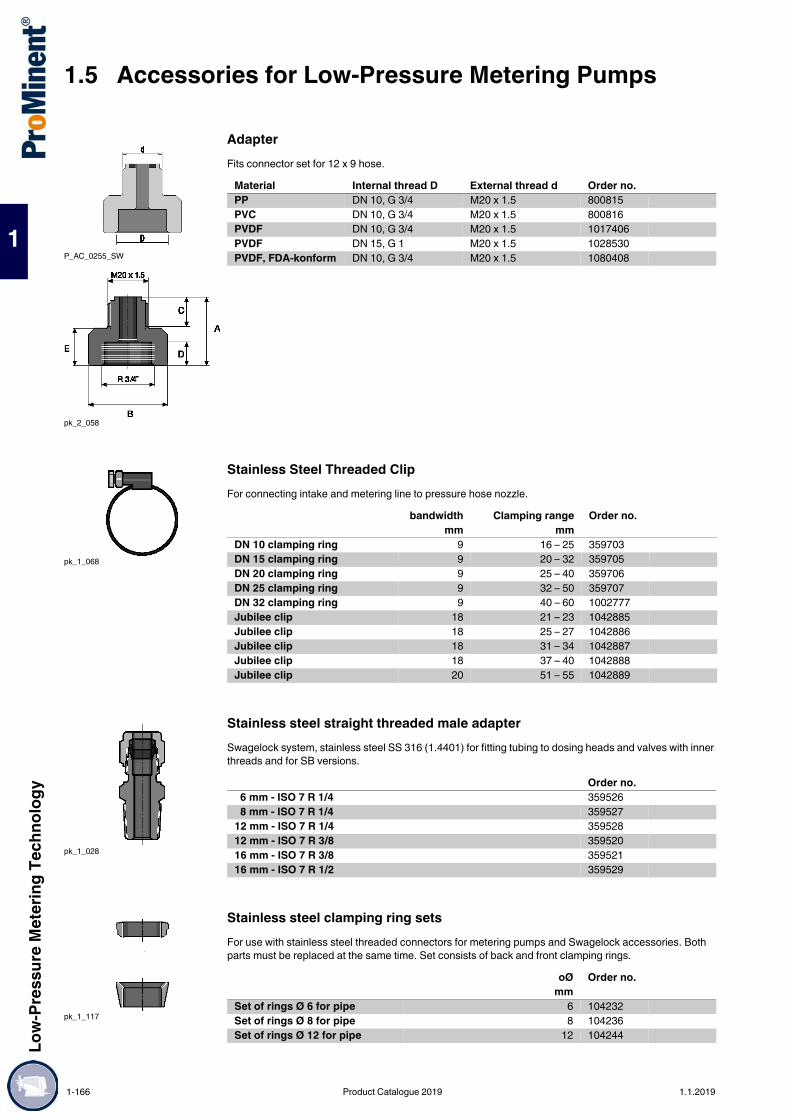
1.5 Accessories for Low-Pressure Metering PumpsLo
w-Pr
essu
re M
eter
ing Te
chno
logy
1
AdapterFits connector set for 12 x 9 hose.
Stainless Steel Threaded ClipFor connecting intake and metering line to pressure hose nozzle.
Stainless steel straight threaded male adapterSwagelock system, stainless steel SS 316 (1.4401) for fitting tubing to dosing heads and valves with inner threads and for SB versions.
Stainless steel clamping ring setsFor use with stainless steel threaded connectors for metering pumps and Swagelock accessories. Both parts must be replaced at the same time. Set consists of back and front clamping rings.
P_AC_0255_SW
pk_2_058
Material Internal thread D External thread d Order no.PP DN 10, G 3/4 M20 x 1.5 800815PVC DN 10, G 3/4 M20 x 1.5 800816PVDF DN 10, G 3/4 M20 x 1.5 1017406PVDF DN 15, G 1 M20 x 1.5 1028530PVDF, FDA-konform DN 10, G 3/4 M20 x 1.5 1080408
pk_1_068
bandwidth Clamping range Order no.mm mm
DN 10 clamping ring 9 16 – 25 359703DN 15 clamping ring 9 20 – 32 359705DN 20 clamping ring 9 25 – 40 359706DN 25 clamping ring 9 32 – 50 359707DN 32 clamping ring 9 40 – 60 1002777Jubilee clip 18 21 – 23 1042885Jubilee clip 18 25 – 27 1042886Jubilee clip 18 31 – 34 1042887Jubilee clip 18 37 – 40 1042888Jubilee clip 20 51 – 55 1042889
pk_1_028
Order no. 6 mm - ISO 7 R 1/4 359526 8 mm - ISO 7 R 1/4 35952712 mm - ISO 7 R 1/4 35952812 mm - ISO 7 R 3/8 35952016 mm - ISO 7 R 3/8 35952116 mm - ISO 7 R 1/2 359529
pk_1_117
oØ Order no. mm
Set of rings Ø 6 for pipe 6 104232Set of rings Ø 8 for pipe 8 104236Set of rings Ø 12 for pipe 12 104244
1-166 Product Catalogue 2019 1.1.2019

Low-
Pres
sure
Met
ering
Tech
nolog
y
1.5 Accessories for Low-Pressure Metering Pumps
1
Stainless steel threaded connectorSerto system for connecting PE or PTFE discharge line to stainless steel pipe, made from stainless steel with clamping ring, but without support insert (parts in contact with chemicals stainless steel 1.4571).
PTFE Formed Composite SealsFormed composite seals to be used on grooved sealing surfaces (e.g. pump valve and grooved inserts from ProMinent).
Set of elastomer flat packing sealsComprising two EPDM and two FKM seals. An elastomer flat seal should be used with non-grooved sealing surfaces. Leaks may occur at the connection if a PTFE shaped composite seal is used.
pk_1_118
Order no.6 mm outer diameter to 6 mm outer diameter stainless steel pipe 3593178 mm outer diameter to 8 mm outer diameter stainless steel pipe 35931812 mm outer diameter to 12 mm outer diameter stainless steel pipe 359320
pk_2_130
DN Material D d Order no.DIN / ANSI mm mmDN 10 PTFE 23.8 14.0 1019364DN 15 PTFE 29.5 18.0 1019365DN 20 PTFE 38.0 22.6 1019366DN 25 PTFE 44.0 27.6 1019367DN 32 PTFE 56.0 34.6 1019353DN 40 PTFE 62.0 40.6 1019368
pk_2_048
D d Order no. mm mm
DN 10 23.5 14.0 1024159DN 15 29.5 18.0 1024160DN 20 38.0 22.6 1036254DN 25 44.0 28.0 1024161DN 32 56.0 36.0 1024162DN 40 62.0 41.0 1029508
1.1.2019 Product Catalogue 2019 1-167

1.5 Accessories for Low-Pressure Metering PumpsLo
w-Pr
essu
re M
eter
ing Te
chno
logy
1
Flange MountingsFlange connection in line with DIN 2566 for ProMinent® valve sizes.
Further material versions and details available on request.
Flat Seals for Threaded Flange to DIN 2566
Flange mountings as DIN 2629. To order for Meta HK and Makro TZ HK plunger metering pumps.FKM = Fluorine Rubber
pk_2_047
P_AC_0263_1_SW1PVDF with collar
P_AC_0264_SW11.4571/1.4404 with collar
Material G/DN Pressure rating
b Ø LK d2 Order no.
DIN / ANSI PN mm mm mmPVDF – G 3/4 - DN 10 PN 16 12.4 60 14 1036274PVDF – G 1 - DN 15 PN 16 13.0 65 14 1036275PVDF – G 1 1/4 - DN 20 PN 16 15.0 75 14 1036276PVDF – G 1 1/2 - DN 25 PN 16 16.0 85 14 1036277PVDF – G 2 - DN 32 PN 16 18.0 100 18 1036278PVDF – G 2 1/4 - DN 40 PN 16 20.0 100 18 10390371.4404 – G 3/4 - DN 15 PN 40 12.0 65 14 8039461.4404 – G 1 - DN 15 PN 40 12.0 65 14 8039401.4404 – G 1 1/4 - DN 20 PN 40 15.0 75 14 8039411.4404 – G 1 1/2 - DN 25 PN 40 15.0 85 14 8039421.4404 – G 2 - DN 32 PN 40 18.0 100 18 10362831.4404 – G 2 1/4 - DN 40 PN 40 20.0 110 18 8039431.4404 – G 2 3/4 - DN 50 PN 40 25.0 125 18 10204531.4404 – G 2 1/2 - DN 65 PN 40 20.0 145 18 1010700PVDF with collar* G 3/4 - DN 10 PN 16 12.5 60 14 1036279PVDF with collar* G 1 - DN 15 PN 16 13.5 65 14 1036280PVDF with collar* G 1 1/2 - DN 25 PN 16 16.0 85 14 1036281PVDF with collar* G 2 - DN 32 PN 16 18.0 100 18 10362821.4571 with collar* G 3/4 - DN 10
(DIN 2637)PN 100 20.0 70 14 1006005
1.4571 with collar* G 1 - DN 15 (DIN 2637)
PN 40 16.0 65 14 1006006
1.4404 with collar* G 1 1/2 - DN 25 (DIN 1092-1)
PN 40 18.0 85 14 1041796
1.4404 with collar* G 2 - DN 32 (DIN 1092-1)
PN 40 18.0 100 18 1041797
* Use flange mountings with a collar for pumps Sigma/ 1, Sigma/ 2 with DN 15 connector and Sigma/ 3 pumps with DN 25 connector. Sigma/ 3-DN25 1“ EN 1092-11.4404 part no: 1041796
pk_2_048
Material G/DN D d Order no.DIN / ANSI mm mm
PTFE G 3/4 - DN 15 52 12 483938PTFE G 1 - DN 15 52 17 483924PTFE G 1 1/4 - DN 20 62 22 483925PTFE G 1 1/2 - DN 25 72 27 483926PTFE G 2 - DN 32 83 33 1007541PTFE G 2 1/4 - DN 40 92 40 483928PTFE G 2 3/4 - DN 50 108 50 483929PTFE G 3 - DN 65 130 60 1020466FKM G 3/4 - DN 15 52 12 483939FKM G 1 - DN 15 52 17 483942FKM G 1 1/4 - DN 20 62 22 483943FKM G 1 1/2 - DN 25 72 27 483944FKM G 1 1/2 - DN 32 83 33 1007542FKM G 2 1/4 - DN 40 92 40 483946FKM G 2 3/4 - DN 50 108 50 483947FKM G 3 - DN 65 130 60 1020467
1-168 Product Catalogue 2019 1.1.2019

Low-
Pres
sure
Met
ering
Tech
nolog
y
1.5 Accessories for Low-Pressure Metering Pumps
1
PP Pressure AccumulatorPlease note: Only use pulsation dampers in conjunction with an overflow device with adjustable back pressure / relief valve.With this: Wall bracket for accumulator available in PP and PVC, consisting of pipe clamp, mounting plate and connecting nipple.Operating range20 °C - max. operating pressure 10 bar40 °C - max. operating pressure 6 bar
Accumulator PP (2– 4 l volume)
PP In-Line Pressure AccumulatorOperating range20 °C - max. operating pressure 10 bar40 °C - max. operating pressure 6 bar
1.5.3.8 Pressure Accumulator
pk_1_006
Volume Permissiblestroke volume
Connection Fig. Order no.
l mlSize 0* 0.15 1.0 M 20 x 1,5 pk_1_006 1021157Size I 0.35 2.5 DN 8 pk_1_065 243218
* With bleed valve. Install directly at the pressure connector.
Connection A B Ø DSize 0 M 20 x 1.5 - 225 49Size I DN 8 150 170 75Size II DN 10 192 220 110Size II DN 15 200 220 110
pk_2_042
Volume Connection Ø L1 L2 Order no. l mm mm mm2 G 1 1/4 – DN 20 without connector parts 140 290 220 2432114 G 1 1/2 – DN 25 without connector parts 160 410 320 243212
pk_1_065_1
Volume Permissible dis-placement
Connection Order no.
lSize II 1 up to 5 ml G 3/4 – DN 10 243219Size II 1 up to 5 ml G 1 – DN 15 243220
1.1.2019 Product Catalogue 2019 1-169

1.5 Accessories for Low-Pressure Metering PumpsLo
w-Pr
essu
re M
eter
ing Te
chno
logy
1
PVC Pressure AccumulatorPlease note: Only use pulsation dampers in conjunction with an overflow device with adjustable back pressure / relief valve.With this: Wall bracket for accumulator available in PP and PVC, consisting of pipe clamp, mounting plate and connecting nipple.Operating range20 °C - max. operating pressure 10 bar40 °C - max. operating pressure 6 bar
* Caution: The product contains adhesive joints with Tangit. Please note the resistance of Tangit adhesive.
Accumulator PVC (2– 4 l volume)Operating range20 °C - max. operating pressure 10 bar40 °C - max. operating pressure 6 bar
* Caution: The product contains adhesive joints with Tangit. Please note the resistance of Tangit adhesive.
PVC In-Line AccumulatorOperating range20 °C - max. operating pressure 10 bar40 °C - max. operating pressure 6 bar
* Caution: The product contains adhesive joints with Tangit. Please note the resistance of Tangit adhesive.
pk_1_065
Volume Permissiblestroke volume
Connection Fig. Order no.
l mlSize 0* 0.15 1.0 M 20 x 1,5 pk_1_006 1021120Size I 0.35 2.5 DN 8 pk_1_065 243203
* With ventilation valve. Mounted directly on the pressure connector.
Connection A B Ø DSize 0 M 20 x 1.5 - 225 49Size I DN 8 150 170 75Size II DN 10 192 220 110Size II DN 15 200 220 110
pk_2_042
Volume Connection Ø L1 L2 Order no. l mm mm mm2 G 1 1/4 – DN 20 without connector parts 140 290 220 2432074 G 1 1/2 – DN 25 without connector parts 160 410 320 243208
Volume Permissible dis-placement
Connection Order no.
lSize II 1 up to 5 ml G 3/4 – DN 10 243204Size II 1 up to 5 ml G 1 – DN 15 243205
1-170 Product Catalogue 2019 1.1.2019

Low-
Pres
sure
Met
ering
Tech
nolog
y
1.5 Accessories for Low-Pressure Metering Pumps
1
Stainless Steel AccumulatorMax. operating pressure 10 bar.
Accumulator stainless steel (2 – 4 l volume)Max. operating pressure 10 bar
Wall Bracket for AccumulatorAvailable in material version PP and PVC, consisting of pipe clamp, mounting plate and connecting nipple
pk_1_128
pk_1_063
Volume Permissiblestroke volume
Connection Fig. Order no.
l mlSize 0 0.35 2.5 for pipe oØ 6 pk_1_128 914510Size I 0.35 2.5 for pipe oØ 8 pk_1_128 914511Size I 0.35 2.5 for pipe oØ 12 pk_1_128 914512
pk_2_033
Volume Connection Ø L1 L2 Order no. l mm mm mm2 G 1 1/4 – DN 20 without connector
parts140 272 222 243214
4 G 1 1/2 – DN 25 without connector parts
160 365 312 243215
pk_1_061
Ø Order no. mm
for accumulator volume 0.35 l 75 818501For accumulator volume 2 l 110 818502For accumulator volume 2 l 140 803645For accumulator volume 4 l 160 803646
1.1.2019 Product Catalogue 2019 1-171

1.5 Accessories for Low-Pressure Metering PumpsLo
w-Pr
essu
re M
eter
ing Te
chno
logy
1
Pulsation dampers are available in different versions: as in-line dampers and as accumulators.Pulsation dampers are used for low-pulsation metering and to reduce the flow resistance with long metering lines. They are also ideally suited to viscous media. The gas cushion between the housing and hose is compressed when the metering pump has a pressure stroke, at the same time as a partial volume of the medium is metered into the metering line. The overpressure that forms in the gas cushion causes the compressed volume to be transported on at the following suction stroke and the original, relaxed volume of gas is present againPP In-Line DamperPlease note: Only use pulsation dampers in conjunction with an overflow device with adjustable back pressure / relief valve.With this: Dummy plugs to seal the output side of the damper in installations with a T-piece.
* Chlorosulfonated polyethylene
PP In-Line DamperDamper diaphragm is replaceable, seals made of EPDM. Medium temperature max. 50 °CPre-pressure is approx. 0.6 x operating pressure.
* Chlorosulfonated polyethyleneFor other sizes (0.2 l and 0.5 l) see in-line pulsation damper PVDF.For other sizes (0.2 l and 0.5 l), see PVDF inline pulsation damper.
PVC blanking threaded connector
1.5.3.9 Pulsation Damper / Diaphragm Accumulator for Low Pressure Metering Pumps
Important:Protect the pulsation dampers in principle with a relief valve.
Operating conditions 5 - 30 °C - max. operating pressure 10 bar 40 °C - max. operating pressure 8 bar 60 °C - max. operating pressure 4 bar
P_AC_0180_SW
Volume Damper diaphragm
Seal material
Connection Order no.
lPPE in-line damper 0.05 CSM* EPDM M 20 x 1,5 1026768PPB in-line damper 0.05 FKM FKM M 20 x 1,5 1026771
Volume Max.pressure
Damper diaphragm
Connection Order no.
l barPPE in-line damper 0.05 10 CSM* G 3/4 - DN 10 1026769PPB in-line damper 0.05 10 FKM G 3/4 - DN 10 1026772PDS 2.5 2.50 10 Hypalon G 2 – DN 32 1001344PDS 2.5 2.50 10 FKM G 2 – DN 32 1001345
Material Connection Order no.PP M 20 x 1,5 1030200PP G 3/4 – DN 10 1001352
1-172 Product Catalogue 2019 1.1.2019

Low-
Pres
sure
Met
ering
Tech
nolog
y
1.5 Accessories for Low-Pressure Metering Pumps
1
PVC In-Line DamperPlease note: Only use pulsation dampers in conjunction with an overflow device with adjustable back pressure / relief valve.With this: Dummy plugs to seal the output side of the damper in installations with a T-piece.
* Chlorosulfonated polyethylene
PVC In-Line DamperRemovable hose, FKM seals.
* Chlorosulfonated polyethyleneFor other sizes (0.2 l and 0.5 l) see in-line pulsation damper PVDF.
PVC blanking threaded connector
Operating conditions 5 - 20 °C - max. operating pressure 10 bar40 °C - max. operating pressure 6 bar60 °C - max. operating pressure 2 bar
Volume Damper diaphragm
Seal material
Connection Order no.
lPCE in-line damper 0.05 CSM* EPDM M 20 x 1,5 1026774PCB in-line damper 0.05 FKM FKM M 20 x 1,5 1026777
pk_2_041
Type DimensionsA B C D E
PDS 2.5 541 525 G2 11 99.5
Volume Max. pres-sure
Damper diaphragm
Connection Order no.
l barPCE in-line damper 0.05 10 CSM* G 3/4 – DN 10 1026775PCB in-line damper 0.05 10 FKM G 3/4 – DN 10 1026778PDS 2.5 2.50 10 Hypalon G 2 – DN 32 1001342PDS 2.5 2.50 10 FKM G 2 – DN 32 1001343
Material Connection Order no.PVC M 20 x 1,5 1030458PVC G 3/4 – DN 10 1001349
1.1.2019 Product Catalogue 2019 1-173

1.5 Accessories for Low-Pressure Metering PumpsLo
w-Pr
essu
re M
eter
ing Te
chno
logy
1
PVDF In-Line Pulsation DamperFunction: Hydropneumatic accumulator with baffleThe PVDF accumulator with PTFE diaphragm offers outstanding resistance to chemicals and can therefore be used in connection with a large number of different liquids. The pulsation damper has two liquid connections and can therefore be installed directly in the piping system or be installed diagonally using a blanking plug kit. The baffle in the liquid valve directs the volume flow straight at the diaphragm. This ensures direct contact of the volume flow with the diaphragm. Fluctuations in volume flow are thus optimally balanced out by the enclosed gas volume.Important: Pulsation dampers should be protected by an overflow valve.
The priming pressure is approximately 0.6 x the operating pressure. Maximum medium temperature, 65 °C. Connection parts must be ordered separately.Filling of the reservoir with nitrogen takes place via the VG8 gas filling connector or with compressed air using a standard filling valve (e.g. a car tyre valve).
Connection/Adapter KitsConsisting of PTFE-formed composite seal, insert/adapter and union nut.
Accessories/Spare Parts
pk_2_106_1
Type Volume Max. pressure Connection Order no. l bar
PD In-line 0.2 10 G 1 – DN 15 1026252PD In-line 0.5 10 G 1 – DN 15 1026736PD-Inline 0.2 16 G 1 – DN 15 1033446PD-Inline 0.5 16 G 1 – DN 15 1033447PD-Inline 0.2 25 G 1 – DN 15 1036154PD In-line 0.5 25 G 1 – DN 15 1036155
Attention: If using combustible liquids, nitrogen must be used as a filling gas. Do not use oxygen under any circumstances!
Configuration: DGRL97/23/EC, other acceptances / countries upon requestFluid group: 1 and 2Certificates: Manufacturer's test certificate M DIN55350-18
Wetted materials - FDA physiologically safeManufacturer: HYDAC Technology
Connection PD In-line Connection Piping Material Order no.G 1 – DN 15 DN 10 PP 1029424G 1 – DN 15 DN 10 PVC 1029425G 1 – DN 15 DN 10 PVDF 1029426G 1 – DN 15 DN 15 PP 1029443G 1 – DN 15 DN 15 PVC 1029444G 1 – DN 15 DN 15 PVDF 1029445G 1 – DN 15 DN 20 PP 1029427G 1 – DN 15 DN 20 PVC 1029428G 1 – DN 15 DN 20 PVDF 1029429G 1 – DN 15 DN 25 PP 1029430G 1 – DN 15 DN 25 PVC 1029431G 1 – DN 15 DN 25 PVDF 1029432
Material Order no.Set of plugs PVDF/PTFE 1029446Valve tool for gas valve insert Steel 1029661Separating diaphragm PTFE/NBR 1025235Gas valve assembly 1.4571/FKM/PTFE/MS 1029513Gas valve insert FKM/PTFE /MS 1029514Gas valve insert FKM/PTFE /NIRO 1029515Manometer with connection adapter – 1031556Charging hose with connector for compressed air system, 25 bar; 2.5 m
– 1036156
Charging hose with connector for nitrogen bottle or pressure reducer
– 1036157
1-174 Product Catalogue 2019 1.1.2019

Low-
Pres
sure
Met
ering
Tech
nolog
y
1.5 Accessories for Low-Pressure Metering Pumps
1
Stainless Steel Pulsation Damper
Mounting Clamp for Stainless Steel Pulsation Damper
Inflation and testing unit for pulsation damperThe inflation and testing unit is used to recharge accumulators with nitrogen and check or alter the existing pre-filling pressure.It contains: Checking and filling system with pressure gauge, non-return valve on the inlet, integrated bleed valve,
valve stem to open gas inlet valve on accumulator. Charging hose, Length 2 m
pk_2_101Admissible operating temperature: -10 to +80 °C. Response pressure: 2 bar (nitrogen). Other accumulator/diaphragm materials available on request.
Volume Max.pressure
Diaphragm material
Connector G A Ø D Order no.
l bar mm mm0.16 180 NBR Rp 1/2 124 74 10086090.16 180 Butyl Rp 1/2 124 74 10086100.16 180 FKM Rp 1/2 124 74 10086110.32 160 NBR Rp 1/2 137 93 10086120.32 160 Butyl Rp 1/2 137 93 10086130.32 160 FKM Rp 1/2 137 93 10086440.75 140 NBR Rp 1/2 168 121 10086450.75 140 Butyl Rp 1/2 168 121 10086460.75 140 FKM Rp 1/2 168 121 10086472.00 100 NBR Rp 3/4 224 167 10086482.00 100 Butyl Rp 3/4 224 167 10086492.00 100 FKM Rp 3/4 224 167 10086504.00 50 NBR Rp 3/4 360 170 10086514.00 50 Butyl Rp 3/4 360 170 10086524.00 50 FKM Rp 3/4 360 170 10086530.75 140 NBR Rp 1 168 121 10276170.75 140 Butyl Rp 1 168 121 10276180.75 140 FKM Rp 1 168 121 10276192.00 100 NBR Rp 1 1/2 224 167 10276202.00 100 Butyl Rp 1 1/2 224 167 10276212.00 100 FKM Rp 1 1/2 224 167 10276224.00 50 NBR Rp 1 1/2 360 170 10276234.00 50 Butyl Rp 1 1/2 360 170 10276244.00 50 FKM Rp 1 1/2 360 170 1027625
pk_2_102
Volume Number of Clamps Ø D Order no. l mm0.16 1 74 10086640.32 1 93 10086650.75 1 121 10086662.00 1 167 10086674.00 2 170 1008668
pk_2_116
Adjustment range Order no.Up to 25 bar 1008769Up to 100 bar 1008669Up to 250 bar 1008670
1.1.2019 Product Catalogue 2019 1-175

1.5 Accessories for Low-Pressure Metering PumpsLo
w-Pr
essu
re M
eter
ing Te
chno
logy
1
Pulsation dampers with separating bubble for providing separation between the gas cushion and metered chemical are used for low-pulsation metering as well as for reducing the flow resistance in long metering lines and in connection with viscous media. The response pressure of the gas cushion should be approx. 60-80 % of the operating pressure.Important: When using a pulsation damper, the pressure relief valve should be fitted with an adjustable back pressure valve.
PVC AccumulatorsAccumulator removable, FKM seals.Operating range (0.5 / 1 l)25 °C - max. operating pressure 10 bar40 °C - max. operating pressure 6 bar Operating range (2.5 / 5 l)25 °C - max. operating pressure 6 bar40 °C - max. operating pressure 4 bar
* Caution: The product contains adhesive joints with Tangit. Please note the resistance of Tangit adhesive.
PP AccumulatorsAccumulator removable, FKM seals.Operating range (0.5 / 1 l)25 °C - max. operating pressure 10 bar40 °C - max. operating pressure 6 bar Operating range (2.5 / 5 l)25 °C - max. operating pressure 6 bar40 °C - max. operating pressure 4 bar
1.5.3.10 Accumulators
pk_2_038
Volume Diaphragm ma-terial
Connection L Ø D LA Order no.
l mm mm mm0.5 Butyl G 1 - DN 15 361 145 100 7916910.5 FKM G 1 - DN 15 361 145 100 7916951.0 Butyl G 1 1/4 - DN 20 411 170 100 7916921.0 FKM G 1 1/4 - DN 20 411 170 100 7916962.5* Butyl G 1 1/2 - DN 25 571 170 190 7916932.5* FKM G 1 1/2 - DN 25 571 170 190 791697
Volume Diaphragm material
Connection L Ø D LA Order no.
l mm mm mm0.5 Butyl G 1 - DN 15 361 145 100 7921280.5 FKM G 1 - DN 15 361 145 100 7921321.0 Butyl G 1 1/4 - DN 20 411 170 100 7921291.0 FKM G 1 1/4 - DN 20 411 170 100 7921332.5 Butyl G 1 1/2 - DN 25 571 170 190 7921302.5 FKM G 1 1/2 - DN 25 571 170 190 792134
1-176 Product Catalogue 2019 1.1.2019

Low-
Pres
sure
Met
ering
Tech
nolog
y
1.5 Accessories for Low-Pressure Metering Pumps
1
Pulsation dampers with no diaphragm separating the gas cushion and the chemical are used to produce minimal pulsation metering and to reduce flow resistance in long pipes and when metering viscous liquids.Important: When using accumulators or pulsation dampers it is imperative that a relief valve with an adjustable back pressure valve is fitted.PVC Vacuum CylinderVacuum cylinder as priming aid for long suction line and viscous media. Housing – with transparent middle section. With connector for vacuum pump.Max. operating pressure: 2 bar at 40 °C operating temperature.Max. permitted vacuum pressure 300 mbar absoluteWith this: Vacuum pump assembly
* Approximate values* Caution: The product contains adhesive joints with Tangit. Please note the resistance of Tangit adhesive.
Vacuum Pump Assembly / Priming AidFor pulsation dampers, suction side (vacuum cylinder accumulator).
Suction pressure regulatorThe suction pressure regulator is a spring-loaded diaphragm valve (max. 50 l/h) which opens as a result of the pump suction pressure. This ensures that chemicals cannot flow when the pump is not running, nor can a vacuum be created as a result of tube rupture.A ball check valve should be fitted to prevent undesirable suction action at the pump outlet (e.g. siphon effect).An adjustable spring is used to set the maximum required negative pressure for each operating situation up to 400 mbar. For pumps with positive inlet pressure a minimal vacuum of approx. 50 mbar is sufficient. The pump should produce this vacuum in any case, even for an atmospheric pressure inlet.
Connection parts to be ordered separately.* Caution: The product contains adhesive joints with Tangit. Please note the resistance of Tangit adhesive.
1.5.3.11 Vacuum Cylinder
pk_2_044
Volume Connection Seal material L D Order no. l mm mm0.5 G 1 – DN 15 FKM 380* 78 2435910.5 G 1 – DN 15 EPDM 380* 78 10256991.0 G 1 1/4 – DN 20 FKM 440* 86 2435921.0 G 1 1/4 – DN 20 EPDM 440* 86 10257012.5 G 1 1/2 – DN 25 FKM 520* 133 2435932.5 G 1 1/2 – DN 25 EPDM 520* 133 10257025.0 G 2 1/4 – DN 40 FKM 630* 155 2435945.0 G 2 1/4 – DN 40 EPDM 630* 155 1025703
pk_2_045
Material Seals Order no.PVC EPDM 790019
pk_2_079 Max. flow rate 50 l/hMax. feed pressure 4 barMax. intake pressure 0.3 barMax. temperature 40 °CHousing material PVCDiaphragm material FKMSeals FKMBall material GlassSpring material Hastelloy C
Type Connection Order no.SDR 50 For solenoid-driven pumps M 20 x 1,5 1005505SDR 50 For motor-driven pumps up to 50 l/h G 3/4 - DN 10 1005506
1.1.2019 Product Catalogue 2019 1-177

1.5 Accessories for Low-Pressure Metering PumpsLo
w-Pr
essu
re M
eter
ing Te
chno
logy
1
Variable suction lance without level switchVariable suction lance without level switch for connection to 5 to 60 litre disposable tanks, comprising a support pipe, foot valve, height-adjustable Ø 50 screw cap and 2 m long suction line. Length 640 mm.Note: The required screw cap Ø 44 is available as a spare part for storage tank opening Ø 44 and can be swapped by the customer for the screw cap Ø 50.To fit metering pumps of the alpha and Pneumados product ranges.
Variable suction lance without level switch for 200-litre barrelVariable suction lance without level switch for connection to 200 litre barrel, comprising a support pipe, foot valve, height-adjustable 2" screw plug (DIN S70x6) and 3 m long suction line. Length 1,000 mm.Note: Adapters for other threads are available on request.To fit metering pumps of the alpha and Pneumados product ranges.
1.5.3.12 Suction Lances, Suction Kit Without Level Switch
pk_1_067
Material PPE PCBSupport pipe and foot valve PP PVCSeals and valve ball EPDM/ceramic FKM/ceramicHose PE Soft PVC
Material Length Hose o∅ x i∅ For tank Order no. mm mm
PPE 640 6 x 4 5–60 l / 50 mm 790539PPE 640 8 x 5 5–60 l / 50 mm 790540PPE 640 12 x 9 5–60 l / 50 mm 790541PCB 640 6 x 4 5–60 l / 50 mm 790536PCB 640 8 x 5 5–60 l / 50 mm 790537PCB 640 12 x 9 5–60 l / 50 mm 790538
pk_1_125
Material PPE PCBSupport pipe and foot valve PP PVCSeals and valve ball EPDM/ceramic FKM/ceramicHose PE Soft PVC
Material Length Hose o∅ x i∅ For tank Order no. mm mm
PPE 1000 6 x 4 200 l / 2" 790545PPE 1000 8 x 5 200 l / 2" 790546PPE 1000 12 x 9 200 l / 2" 790547PCB 1000 6 x 4 200 l / 2" 790542PCB 1000 8 x 5 200 l / 2" 790543PCB 1000 12 x 9 200 l / 2" 790544
1-178 Product Catalogue 2019 1.1.2019
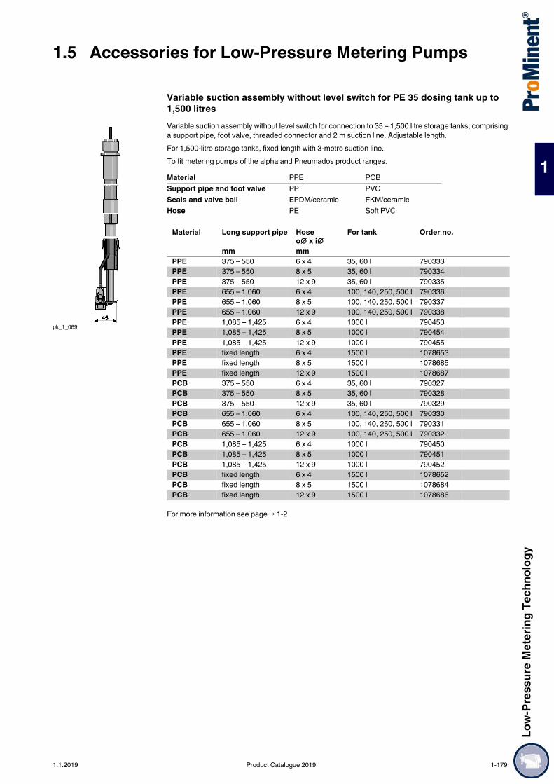
Low-
Pres
sure
Met
ering
Tech
nolog
y
1.5 Accessories for Low-Pressure Metering Pumps
1
Variable suction assembly without level switch for PE 35 dosing tank up to 1,500 litresVariable suction assembly without level switch for connection to 35 – 1,500 litre storage tanks, comprising a support pipe, foot valve, threaded connector and 2 m suction line. Adjustable length.For 1,500-litre storage tanks, fixed length with 3-metre suction line.To fit metering pumps of the alpha and Pneumados product ranges.
For more information see page → 1-2
pk_1_069
Material PPE PCBSupport pipe and foot valve PP PVCSeals and valve ball EPDM/ceramic FKM/ceramicHose PE Soft PVC
Material Long support pipe Hose o∅ x i∅
For tank Order no.
mm mmPPE 375 – 550 6 x 4 35, 60 l 790333PPE 375 – 550 8 x 5 35, 60 l 790334PPE 375 – 550 12 x 9 35, 60 l 790335PPE 655 – 1,060 6 x 4 100, 140, 250, 500 l 790336PPE 655 – 1,060 8 x 5 100, 140, 250, 500 l 790337PPE 655 – 1,060 12 x 9 100, 140, 250, 500 l 790338PPE 1,085 – 1,425 6 x 4 1000 l 790453PPE 1,085 – 1,425 8 x 5 1000 l 790454PPE 1,085 – 1,425 12 x 9 1000 l 790455PPE fixed length 6 x 4 1500 l 1078653PPE fixed length 8 x 5 1500 l 1078685PPE fixed length 12 x 9 1500 l 1078687PCB 375 – 550 6 x 4 35, 60 l 790327PCB 375 – 550 8 x 5 35, 60 l 790328PCB 375 – 550 12 x 9 35, 60 l 790329PCB 655 – 1,060 6 x 4 100, 140, 250, 500 l 790330PCB 655 – 1,060 8 x 5 100, 140, 250, 500 l 790331PCB 655 – 1,060 12 x 9 100, 140, 250, 500 l 790332PCB 1,085 – 1,425 6 x 4 1000 l 790450PCB 1,085 – 1,425 8 x 5 1000 l 790451PCB 1,085 – 1,425 12 x 9 1000 l 790452PCB fixed length 6 x 4 1500 l 1078652PCB fixed length 8 x 5 1500 l 1078684PCB fixed length 12 x 9 1500 l 1078686
1.1.2019 Product Catalogue 2019 1-179

1.5 Accessories for Low-Pressure Metering PumpsLo
w-Pr
essu
re M
eter
ing Te
chno
logy
1
Suction assembly PPE for tanks up to 1,500 litres
Suction assembly without level switch comprising a support pipe, foot valve and threaded connector. The length L of the support pipe can be adjusted (shortened) by the customer.Note: In applications with a hose, the suction assembly/hose connector kit, consisting of a PVDF screw-in nozzle and a PTFE composite seal, can be used.
Suction assembly PCB for tanks up to 1,500 litres
Suction assembly without level switch comprising a support pipe, foot valve and threaded connector. The length L of the support pipe can be adjusted (shortened) by the customer.Note: In applications with a hose, the suction assembly/hose connector kit, consisting of a PVDF screw-in nozzle and a PTFE composite seal, can be used.Important: The product contains connections bonded with Tangit. Always note the durability of Tangit adhesive.
P_AC_0203_SW
Connection G Storagetank
Ø Ø D L Order no.
l mm mm mmDN 10 3/4 1000 20 47 1,340 790389DN 15 1 1000 20 47 1,320 790394DN 20 1 1/4 1000 25 55 1,345 790395DN 25 1 1/2 1000 32 60 1,315 790396DN 32 2 1000 40 74 1,170 1005524DN 10 3/4 1500 20 47 1,830 1077554
Connection G Storagetank
Ø Ø D L Order no.
l mm mm mmDN 10 3/4 1000 20 47 1,340 790387DN 15 1 1000 20 47 1,320 790391DN 20 1 1/4 1000 25 55 1,345 790392DN 25 1 1/2 1000 32 60 1,315 790393DN 32 2 1000 40 74 1,170 1005525DN 10 3/4 1500 20 47 1,830 1077555
1-180 Product Catalogue 2019 1.1.2019

Low-
Pres
sure
Met
ering
Tech
nolog
y
1.5 Accessories for Low-Pressure Metering Pumps
1
Variable suction lance with two-stage level switchVariable suction lance with two-stage level switch for connection to 5 - 60 litre disposable tanks, comprising a support pipe, foot valve, level switch with round plug, height-adjustable Ø 50 mm screw cap and 2 m long suction line. Length 640 mm.Switch mode when liquid level low: 2 x N/CSuitable for metering pumps of the Beta®, gamma/ X, delta® and DULCO®flex DF4a (6 x 4) product ranges.Note: The required screw cap Ø 44 is available as a spare part for storage tank opening Ø 44 and can be swapped by the customer for the screw cap Ø 50.Variable suction lance with two-stage level switch for 200-litre barrelVariable suction lance with two-stage level switch for connection to 200 litre barrel, comprising a support pipe, foot valve, level switch with round connector, height-adjustable sealing plug and 3 m long suction line. Length 1000 mm.Switch mode when liquid level low: 2 x N/CSuitable for metering pumps of the Beta®, gamma/ X and delta® product ranges.Note: Adapters for other threads are available on request
1.5.3.13 Suction Lances, Suction Assemblies with Two-Stage Level Switch
pk_1_075
Material PPE PCBSupport pipe and foot valve PP PVCSeals EPDM FKMHose PE Soft PVC
Material Length Hose o∅ x i∅ For tank Order no. mm mm
PPE 640 6 x 4 5–60 l / 50 mm 802277PPE 640 8 x 5 5–60 l / 50 mm 802278PPE 640 12 x 9 5–60 l / 50 mm 790372PCB 640 6 x 4 5–60 l / 50 mm 802077PCB 640 8 x 5 5–60 l / 50 mm 802078PCB 640 12 x 9 5–60 l / 50 mm 790371
pk_1_076
Material PPE PCBSupport pipe and foot valve PP PVCSeals EPDM FKMHose PE Soft PVC
Material Length Hose o∅ x i∅ For tank Order no. mm mm
PPE 1000 6 x 4 200 l 802279PPE 1000 8 x 5 200 l 802280PPE 1000 12 x 9 200 l 790374PCB 1000 6 x 4 200 l 802079PCB 1000 8 x 5 200 l 802080PCB 1000 12 x 9 200 l 790373
1.1.2019 Product Catalogue 2019 1-181

1.5 Accessories for Low-Pressure Metering PumpsLo
w-Pr
essu
re M
eter
ing Te
chno
logy
1
Suction lance with two-stage level switch for 60-litre canister, fixed length, gas-tightVariable suction lance with 2-stage level switch for connection to 60 litre canister, gas-tight, comprising a support pipe, foot valve, level switch with round plug, Ø 55 mm screw cap and 2 m long suction line. Length 560 mm. Design with vent valve and bleed valve.Switch mode when liquid level low: 2 x N/CSuitable for metering pumps of the Beta®, gamma/ X and delta® product ranges.
Suction lance with two-stage level switchFixed length suction lance made of PVDF with two-stage level switch, consisting of PVDF support pipe, foot valve, two-stage level switch with open end and PTFE suction line 8 x 6 mm.Note: A matching connector kit for hose 8/6 to standard 6/4, 8/5 and 12/9 connectors is included in the scope of delivery.Switch mode when liquid level low: 2 x N/CSuitable for metering pumps of the Beta®, gamma/ X and delta® product ranges using a 2 m level sensor cable, order no. 707715.
P_AC_0052_SW
Material PPE PCBSupport pipe and foot valve PP PVCSeals EPDM FKMHose PE Soft PVC
Material Length Hose o∅ x i∅ For tank Order no. mm mm
PPE 560 6 x 4 60 l / 55 mm 802285PPE 560 8 x 5 60 l / 55 mm 802286PPE 560 12 x 9 60 l / 55 mm 802287PCB 560 6 x 4 60 l / 55 mm 802081PCB 560 8 x 5 60 l / 55 mm 802082PCB 560 12 x 9 60 l / 55 mm 802083
P_AC_0250_SW
Material PVTSupport pipe and foot valve PVDFSeals PTFEHose PTFE
Material Length Hose o∅ x i∅ For tank Order no. mm mm
PVT 350 8 x 6 10–30 l 1038304PVT 650 8 x 6 50–60 l 1038305
1-182 Product Catalogue 2019 1.1.2019

Low-
Pres
sure
Met
ering
Tech
nolog
y
1.5 Accessories for Low-Pressure Metering Pumps
1
Suction lances with continuous level measurementSuction lance with continuous level measurement for connection via the 3-pin float switch input to metering pumps of the product range gamma/ X and gamma/ XL. For precise consumption detection, prediction of chemical range and planning of subsequent deliveries web-based via Dulconnex.The scope of delivery includes a 3 m connecting cable with plug-in connectors for the suction lance and the metering pump as well as a 3 m suction lineWith adjustable screw cap 50 mm, length of suction lance to fit tank size 30 l.Wetted materials PE, ceramic valve ball.
P_AC_0280_SW1
Material PET PET PETSupport pipe and foot valve PE/PVDF PE/PVDF PE/PVDFSeals and valve ball PTFE/ceramic PTFE/ceramic PTFE/ceramicHose PE PE PE
Material Length Hose o∅ x i∅ For tank Order no. mm mm
PET 480 6 x 4 30 l 1094379PET 480 8 x 5 30 l 1094382PET 480 12 x 9 30 l 1094380
1.1.2019 Product Catalogue 2019 1-183

1.5 Accessories for Low-Pressure Metering PumpsLo
w-Pr
essu
re M
eter
ing Te
chno
logy
1
Suction assembly with two-stage level switch for PE 35 dosing tanks up to 1,500 litresVariable suction assembly with two-stage level switch for connection to 35 to 1,500 litre tanks, comprising a support pipe, foot valve, level switch with 3-pin round connector and 2 m long suction line, or 3 m with 1,000 litre tanks. Adjustable length.For 1,500-litre storage tanks, fixed length with 3-metre suction line.Switch mode when liquid level low: 2 x N/CSuitable for metering pumps of the Beta®, gamma/ X and delta® product ranges.
Screw CapFor tanks with opening Ø 44, customers need to order the Ø 44 screw cap as a spare part to replace Ø 50 screw cap.
pk_1_077
Material PPE PCBSupport pipe and foot valve PP PVCSeals EPDM FKMHose PE Soft PVC
Material Long support pipe Hose o∅ x i∅ For tank Order no.mm mm
PPE 375 – 550 6 x 4 35, 60 l 790365PPE 375 – 550 8 x 5 35, 60 l 790366PPE 375 – 550 12 x 9 35, 60 l 790367PPE 655 – 1,060 6 x 4 100–500 l 790368PPE 655 – 1,060 8 x 5 100–500 l 790369PPE 655 – 1,060 12 x 9 100–500 l 790370PPE 1,085 – 1,425 6 x 4 1000 l 790465PPE 1,085 – 1,425 8 x 5 1000 l 790466PPE 1,085 – 1,425 12 x 9 1000 l 790467PPE fixed length 6 x 4 1500 l 1077558PPE fixed length 8 x 5 1500 l 1077519PPE fixed length 12 x 9 1500 l 1077560PCB 375 – 550 6 x 4 35, 60 l 790359PCB 375 – 550 8 x 5 35, 60 l 790360PCB 375 – 550 12 x 9 35, 60 l 790361PCB 655 – 1,060 6 x 4 100–500 l 790362PCB 655 – 1,060 8 x 5 100–500 l 790363PCB 655 – 1,060 12 x 9 100–500 l 790364PCB 1,085 – 1,425 6 x 4 1000 l 790462PCB 1,085 – 1,425 8 x 5 1000 l 790463PCB 1,085 – 1,425 12 x 9 1000 l 790464PCB fixed length 6 x 4 1500 l 1077559PCB fixed length 8 x 5 1500 l 1077520PCB fixed length 12 x 9 1500 l 1077561
pk_1_066Order no.
Ø 44 screw cap 811626
1-184 Product Catalogue 2019 1.1.2019

Low-
Pres
sure
Met
ering
Tech
nolog
y
1.5 Accessories for Low-Pressure Metering Pumps
1
PPE Universal Suction LanceUniversal suction lance made of PP in 4 sizes for use in canisters, barrels or containers. The suction lance is configured as standard with return, ventilation function and 2-stage level monitoring. The height-adjustable level switch and tank threaded connectors ensure flexible adaptation to the process or storage tank height. In addition, the suction tube length can easily be shortened by the customer. A PTFE check ball is incorporated and prevents the suction line from running dry. With IBC container suction lances (1039399, 1046672), the screw lid DN150 can be installed by the customer onto other G2" vent openings.Note: Special designs are available on request.The suction lance is supplied with all additional parts in cardboard packaging.Material version: PP with EPDM seals.Suction connector is not supplied ready mounted. Fittings and pressure hose nozzles in DN 10, DN 15, DN 20, DN 25 (not for canisters) plus FKM seal do form part of the scope of delivery.Return connector is not supplied ready mounted. Fittings and pressure hose nozzles in DN 10, DN 15, plus an FKM blanking plug and seal do not form part of the scope of delivery.Level: In drum and tank lances the level switches are protected by tube pieces. The lance level output is in the form of an M12 plug. Please order the level signal cable for connection to ProMinent metering pumps or a PLC or terminal box separately.Storage tank connector:20 l and 20 - 60 l canisters: Ø 50 screw lid 200 l drum: 70 x 6 opening in plastic bung drumIBC container: DN150 IBC capGeneral Electrical Accessories
PPE Universal Suction Lance, "Physiologically Safe" DesignThe universal suction lance is also available as a "Physiologically safe (FDA) in respect of wetted materials" design.
*Replace the screw lid when using FDA containers.
P_AC_0252_SW
A Overall lengthB Immersion depthC Diameter of the immersion tubeD Threaded connector adjustment rangeE Warning level adjustment rangeF Switch-off level adjustment range
Universal suction lance
A B C Total adjustment range Order no.
D E F mm mm mm mm mm mm
For canister 20 l 542 405 41 100 250 200 1039206For canister 20 -60 l 584 447 41 100 300 200 1038817For drum 200 l 1,072 935 51 50 700 700 1039397For container IBC 1,162 1,025 51 50 800 800 1039399
Universal suction lance
A B C Total adjustment range Order no.
D E F mm mm mm mm mm mm
For 20-litre canister 542 405 41 100 250 200 1046668For 20 – 60-litre canister
584 447 41 100 300 200 1046670
For 200-litre drum 1,072 935 51 50 700 700 1046671for IBC containers* 1,162 1,025 51 50 800 800 1046672
1.1.2019 Product Catalogue 2019 1-185

1.5 Accessories for Low-Pressure Metering PumpsLo
w-Pr
essu
re M
eter
ing Te
chno
logy
1
Suction Lance with Two-Stage Level SwitchSuction lance with 2-stage level switch in Ø 50 PVC protection tube with check valve for DN 10-DN 25, clack valve in DN 32 (valve is not removable).For sizes DN 10/15 and DN 20/25, the connection parts in both sizes and a blanking plate for the return form part of the scope of supply. For the DN 32 suction lance a return line is not possible. Drum suction lances are equipped with a drum lid.2-stage level switch is wired to a terminal in the head.The level sensor cable must be ordered separately.Special designs (materials, functions, Dytex adhesive etc.) are available on request.Reed cable with 3-pin round plug, PE → 1-199* Caution: The product contains adhesive joints with Tangit. Please note the resistance of Tangit adhesive.Suction Lance for 200/600 l Drum
L1: Length up to returnL2: Length up to suction connectorL3: Overall length
Suction Lance for 1000 l Tank
L1: Length up to returnL2: Length up to suction connectorL3: Overall length
Intake Fitting – Hose Connection KitConsisting of PVDF threaded socket and a PTFE-formed composite seal.Suitable for PPE Suction assembly for 1,000 l tank → 1-180
P_AC_0277
Type Suction con-nector DN 1
Return DN 2
Seals L1 L2 L3 Order no.
mm mm mmPCB 10/15 10/15 FKM 1000 1100 1200 1037748PCE 10/15 10/15 EPDM 1000 1100 1200 1037749PCB 20/25 20/25 FKM 1000 1100 1200 1037750PCE 20/25 20/25 EPDM 1000 1100 1200 1037751PCB 32 – FKM – 1100 1200 1037752PCE 32 – EPDM – 1100 1200 1037753
P_AC_0276
Type Suction con-nector DN 1
Return DN 2
Seals L1 L2 L3 Order no.
mm mm mmPCB 10/15 10/15 FKM 1200 1300 1400 1037722PCE 10/15 10/15 EPDM 1200 1300 1400 1037723PCB 20/25 20/25 FKM 1200 1300 1400 1037744PCE 20/25 20/25 EPDM 1200 1300 1400 1037745PCB 32 – FKM – 1300 1400 1037746PCE 32 – EPDM – 1300 1400 1037747
pk_2_140
Connection G Material Ø D Order no. mm
DN 10 3/4 PVDF 16 1029486DN 15 1 PVDF 20 1029487DN 20 1 1/4 PVDF 25 1029488DN 25 1 1/2 PVDF 32 1029489DN 32 2 PVDF 40 1029490
1-186 Product Catalogue 2019 1.1.2019

Low-
Pres
sure
Met
ering
Tech
nolog
y
1.5 Accessories for Low-Pressure Metering Pumps
1
Level Switch Kit Complete, PVDF, Two-Stage with Round Connector or LeadThe level switch kit can be ordered together with the suction fittings DN 10 - DN 32.For level monitoring in the storage tank, two-phase with pre-alarm signalling and deactivation of the metering pump after a further level decrease of 30 mm.
Technical data:Max. switching voltage: 100 VSwitching current: 0.5 ASwitching capacity: 5 W/5 VATemperature range: - 10 °C to 65 °CIP rating: IP 67Switching mode: for level shortage 2 x NC
Material:Body level switch PVDF, float PE, mounting strap PVDF, cable bracket PE, anti-kink device PE, cable PE.
Level switch, single-stage with flat plugSingle-stage level switch with flat plug for level monitoring in the storage tank.Suitable for metering pumps of the D_4a product range.
Technical datamax. switching voltage 48 V,Switching current 0.5 A,Switching power 5 W/5 VA,Temperature range -10 °C to 65 °C, degree of protection IP 67.Switching mode: at liquid level low 1 x N/O.
1.5.3.14 Level Switch, Ceramic Weight, Extension Cable
pk_2_035
Connection Type Cable length Order no. m
DN10/15 with 3-pin round plug 3 1034879DN 20 with 3-pin round plug 3 1034880DN 25 with 3-pin round plug 3 1034881DN 32 with 3-pin round plug 3 1034882DN 10/DN 15 with lead 5 1034883DN 20 with lead 5 1034884DN 25 with lead 5 1034885DN 32 with lead 5 1034886
pk_1_080
Material PVDF/PE PVDF/PVDFLevel switch PVDF PVDFFloat PE foamed PVDFCable PE PE
Material Lead length Order no.PVDF/PE 2 m 1031588PVDF/PE 5 m 1031590PVDF/PVDF 2 m 1034695PVDF/PVDF 5 m 1034696
1.1.2019 Product Catalogue 2019 1-187

1.5 Accessories for Low-Pressure Metering PumpsLo
w-Pr
essu
re M
eter
ing Te
chno
logy
1
Two-Stage Float SwitchTwo-stage level switch for level monitoring in the storage tank with pre-warning alarm message and switch-off of the metering pump after a further 30 mm reduction in level.With a 3-pin round connector for direct connection to metering pump or with 3 leads, e.g. in conjunction with relay control, order no. 914768.Switch mode when liquid level low: 2 x N/CSuitable for metering pumps of the Beta®, gamma/ X and delta® product ranges.
Technical dataMax. switching voltage: 24 V DC, switching current: 0.5 A, Switching power: 5 W/5 VA,Temperature range: - 10 °C to 65 °C, degree of protection IP 67.
Cable assignment on 3-wire cable:
Ceramic Weight for Vertical Fixing of Float Switch
With the two stage float switch with round plug, the weight is pushed up when float is attached.
pk_1_081
Material PVDF/PE PVDF/PVDFLevel switch PVDF PVDFFloat PE foamed PVDFCable PE PE
Material Connection cable Lead length Order no.PVDF/PE Round plug 2 m 1031604PVDF/PE Round plug 5 m 1031606PVDF/PE Open end 2 m 1031607PVDF/PE Open end 5 m 1031609PVDF/PVDF Round plug 2 m 1034697PVDF/PVDF Round plug 5 m 1034698PVDF/PVDF Open end 2 m 1034699PVDF/PVDF Open end 5 m 1034700
Colour Functionblack Earthblue Minimum pre-warningbrown Minimum limit stop
pk_1_082
Ø A B Ø C Weight Type Order no. mm mm mm g
Size 1 25 50 10 60 For round and latch plug 1019244Size 2 39 32 * 65 For round plug/flat connector 404004Size 3 40 50 24 70 For round plug/flat connector 1030189
* Slot 13 x 27 mm
1-188 Product Catalogue 2019 1.1.2019

Low-
Pres
sure
Met
ering
Tech
nolog
y
1.5 Accessories for Low-Pressure Metering Pumps
1
Level switch with support pipeLevel switch for use in media which attack the PE cable of the level switch and/or for stable attachment in conjunction with electric stirrer, FKM seal. Adjustable length.2-stage switch mode when liquid level low: 2 x N/C1-stage switch mode when liquid level low: 1 x N/O
Extension Lead, 3-CoreExtension cable for level switch with 3-pin round plugs, comprising 3 m cable, plug and coupling.
pk_1_084
Material PCBSupport pipe PVCSeals FKMLevel switch PVDFCable PE
Material Long support pipe Level switch Order no.mm
PCB 350 – 550 two-stage with round connector 802010PCB 660 – 1160 two-stage with round connector 802011PCB 350 – 550 single-stage with flat plug 801727PCB 660 – 1160 single-stage with flat plug 801728
pk_1_126 Order no.Extension cable, 3-pin, 3 m length 1005559
1.1.2019 Product Catalogue 2019 1-189

1.5 Accessories for Low-Pressure Metering PumpsLo
w-Pr
essu
re M
eter
ing Te
chno
logy
1
Flushing Assemblies for Motor-Driven Metering PumpsFlushing assemblies for flushing and cleaning liquid end, metering line and metering valve as well as for preventing deposits.
PPE Flushing Device
PCB Flushing Assembly
* Caution: The product contains adhesive joints with Tangit. Please note the resistance of Tangit adhesive.Automatic flushing equipment for the fully automatic flushing of the pump head is possible on request.
1.5.3.15 Fittings
pk_1_057Connection G Order no.DN 10 3/4 809917DN 15 1 809919DN 20 1 1/4 809921DN 25 1 1/2 809923
Connection G Order no.DN 10 3/4 809926DN 15 1 803960DN 20 1 1/4 803961DN 25 1 1/2 803962DN 40 2 1/4 803963
1-190 Product Catalogue 2019 1.1.2019

Low-
Pres
sure
Met
ering
Tech
nolog
y
1.5 Accessories for Low-Pressure Metering Pumps
1
PPE Wall Mounting BracketWall bracket made of fibreglass-reinforced PPE to hold metering pumps, including attachment fittings. Dimensions (L x W x H): 208 x 120 x 140 mm.To fit all metering pumps of the alpha, Beta® and gamma/ X product ranges.The metering pumps of the Beta®/ 4 and gamma/ X product ranges can either be mounted parallel or crosswise to each other.
PP Adapter PlateWith fixing materials for vertical wall-mounting of Beta® or gamma pumps with self-degassing liquid ends. Used with PPE wall bracket.
PP Wall BracketPP wall mounting, holds pump parallel to the wall, includes fixings.Measurements: L x W x H, 230 x 220 x 220 mm
Portable Plastic Pump StandTo accommodate a metering pump of the product range beta® or gamma/ X. The pump stand can either be designed in PP or black PE. It is prepared for accommodating a fixed pipe and has collector equipment for escaping feed chemical, e.g. in the event of a leakage on the suction line or a rupture of the diaphragm.Supplied with carrying handle, but without pump and pipework
PVC Right-Angled Threaded ConnectorFor mounting multifunctional valve onto Beta® or gamma/ L models, self-degassing liquid end version.
* Caution: The product contains adhesive joints with Tangit. Please note the resistance of Tangit adhesive.
1.5.3.16 Wall Brackets for Metering Pumps
pk_1_092Fig. Order no.
for BT4, BT5, gamma/ X, G/ 4, G/ 5, D_4a pk_1_092 810164
pk_1_121
Fig. Order no.for BT4, BT5, gamma/ X pk_1_121 1003030
pk_2_036
Order no.for Vario, Sigma and Meta 1001906
pk_1_093
Fig. Order no.Light grey PP pk_1_093 1000180Black PE pk_1_093 1000181
pk_1_083
Material Fig. Order no.PCE Version PVC/EPDM pk_1_083 1003472PCB Version PVC/FKM pk_1_083 1003318
1.1.2019 Product Catalogue 2019 1-191

1.5 Accessories for Low-Pressure Metering PumpsLo
w-Pr
essu
re M
eter
ing Te
chno
logy
1
PP Foot BracketFor mounting metering pump, includes fixings. Material PP.Measurements: L x W x H 250 x 160 x 150 mm
pk_2_037
Order no.Foot bracket 809910
1-192 Product Catalogue 2019 1.1.2019

Low-
Pres
sure
Met
ering
Tech
nolog
y
1.5 Accessories for Low-Pressure Metering Pumps
1
Spare Parts Kits for Solenoid-Driven Metering Pump Beta® a and gamma/ LSpare parts kits for Beta® a und gamma/ L, consisting of: 1 diaphragm 1 suction valve assembly 1 discharge valve assembly 2 valve balls 1 connector kitStainless steel version without suction valve assembly and without discharge valve assembly1.5.4 Mechanical/Hydraulic Special Accessories
1.5.4.1 Spare Parts Kits
pk_1_008
Type Wetted materials Order no.Type 1000 PPE 1001644
PPB 1001652NPE 1001713NPB 1001721PPT, NPT, PVT 1023107TTT 1001737SST 1001729
Type 1601 PPE 1001645PPB 1001653NPE 1001714NPB 1001722PPT, NPT, PVT 1023108TTT 1001738SST 1001730
Type 1602 PPE 1001646PPB 1001654NPE 1001715NPB 1001723PVT, PPT, NPT 1023109TTT 1001739SST 1001731
Type 1005 and Type 1605 PPE 1001647PPB 1001655NPE 1001716NPB 1001724PVT, PPT, NPT 1023110PVT HV 1019066TTT 1001740SST 1001732
Type 0708 and Type 1008 PPE 1001648PPB 1001656NPE 1001717NPB 1001725PVT, PPT, NPT 1023111PVT HV 1019067TTT 1001741SST 1001733
Type 0413 and Type 0713 PPE 1001649PPB 1001657NPE 1001718NPB 1001726
Type 0220 and Type 0420 PPE 1001650PPB 1001658NPE 1001719NPB 1001727PVT, PPT, NPT 1023113PVT HV 1019070TTT 1001754SST 1001735
1.1.2019 Product Catalogue 2019 1-193
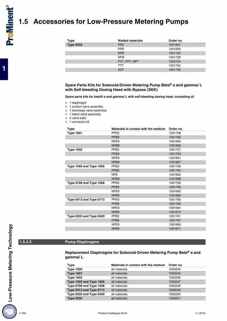
1.5 Accessories for Low-Pressure Metering PumpsLo
w-Pr
essu
re M
eter
ing Te
chno
logy
1
Spare Parts Kits for Solenoid-Driven Metering Pump Beta® a and gamma/ L with Self-bleeding Dosing Head with Bypass (SEK)Spare parts kits for beta® a and gamma/ L with self-bleeding dosing head, consisting of: 1 diaphragm 1 suction valve assembly 1 discharge valve assembly 1 bleed valve assembly 2 valve balls 1 connector kit
Replacement Diaphragms for Solenoid-Driven Metering Pump Beta® a and gamma/ L
Type 0232 PPE 1001651PPB 1001659NPE 1001720NPB 1001728PVT, PPT, NPT 1023124TTT 1001755SST 1001736
Type Materials in contact with the medium Order no.Type 1601 PPE9 1001756
PPB9 1001762NPE9 1001660NPB9 1001666
Type 1602 PPE9 1001757PPB9 1001763NPE9 1001661NPB9 1001667
Type 1005 and Type 1605 PPE9 1001758PPB9 1001764NPE 1001662NPB9 1001668
Type 0708 and Type 1008 PPE9 1001759PPB9 1001765NPE9 1001663NPB9 1001669
Type 0413 and Type 0713 PPE9 1001760PPB9 1001766NPE9 1001664NPB9 1001670
Type 0220 and Type 0420 PPE9 1001761PPB9 1001767NPE9 1001665NPB9 1001671
Type Wetted materials Order no.
1.5.4.2 Pump Diaphragms
Type Materials in contact with the medium Order no.Type 1000 all materials 1000244Type 1601 all materials 1000245Type 1602 all materials 1000246Type 1005 and Type 1605 all materials 1000247Type 0708 and Type 1008 all materials 1000248Type 0413 and Type 0713 all materials 1000249Type 0220 and Type 0420 all materials 1000250Type 0232 all materials 1000251
1-194 Product Catalogue 2019 1.1.2019

Low-
Pres
sure
Met
ering
Tech
nolog
y
1.5 Accessories for Low-Pressure Metering Pumps
1
For on-site retrofitting of metering pumps and accessories, for applications where standard materials are unsuitable. Supplied loose only, not fitted.
Valve balls
* not suitable PVT valve material.
Valve springs for liquid endsWith approx. 0.1 bar priming pressure for spring loading of the valve balls in the liquid end. Recommended to improve the valve function and increase metering accuracy, in particular for viscous metering media above 50 mPas.
Valve springs for injection valvesApprox. 0.5/1/2 bar prepressure for increasing metering accuracy and preventing suction and siphoning effect.
1.5.4.3 Custom Valve Balls/Valve Springs
pk_1_102
Material Ø Order no. mm
PTFE 4.7 for valve Ø 6 mm 404255PTFE 9.5 for valve Ø 8 and 12 mm 404258PTFE 11.0 for valve DN 10 404260PTFE 16.0 to valve DN 15* 404259Ceramic 4.7 for valve Ø 6 mm 404201Ceramic 9.2 for valve Ø 8 and 12 mm 404281Ceramic 11.0 for valve DN 10 404277Ceramic 16.0 to valve DN 15* 4042751.4404 4.7 for valve Ø 6 mm 4042331.4404 9.5 for valve Ø 8 and 12 mm 404240PTFE 20.0 to valve DN 20 404256PTFE 25.0 to valve DN 25 404257PTFE 38.1 to valve DN 40 404261Keramik 20.0 to valve DN 20 404273Keramik 25.0 to valve DN 25 404274Keramik 38.1 to valve DN 40 404278
pk_1_103
Material Primingpressure
Order no.
bar1.4571 0.1 for valve 4.7 4694061.4571 0.1 for valve 9.2 4694031.4571 0.1 for mikro g/ 5 4694371.4571 0.1 for mikro g/ 5 4694381.4571 0.1 for mikro g/ 5 469439Hast. C 0.1 for valve DN 10 469114Hast. C 0.1 for valve DN 15 469107Hast. C 0.1 for valve DN 20 4694511.4571 0.1 for valve DN 25 4694521.4571 0.10.1 for connector R 1/4” Meta/Makro TZ HK 4694611.4571 0.10.1 for R 3/8” connector Makro TZ HK 469462
pk_1_104
Material Primingpressure
Order no.
bar1.4571 1.0 for R 1/4" - Ø 6 mm connector 469401Hast. C 0.5 for R 1/2" - Ø 6, 8 and 12 mm connector 469404Hast. C 1.0 for R 1/2" - Ø 6, 8 and 12 mm connector 469413Hast. C 2.0 for R 1/2" - Ø 6, 8 and 12 mm connector 469410Hast. C 0.5 for DN 10 469115Hast. C 1.0 for DN 10 469119Hast. C 0.5 for DN 15 469108Hast. C 1.0 for DN 15 469116
1.1.2019 Product Catalogue 2019 1-195
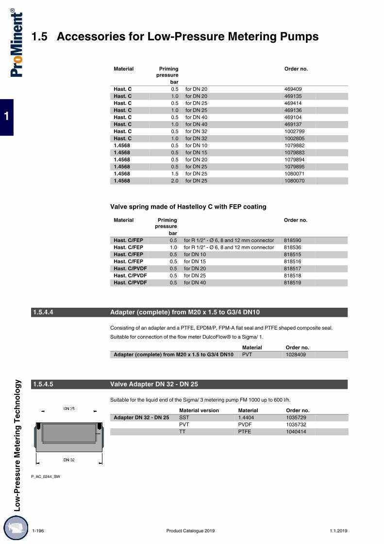
1.5 Accessories for Low-Pressure Metering PumpsLo
w-Pr
essu
re M
eter
ing Te
chno
logy
1
Valve spring made of Hastelloy C with FEP coating
Consisting of an adapter and a PTFE, EPDM/P, FPM-A flat seal and PTFE shaped composite seal.Suitable for connection of the flow meter DulcoFlow® to a Sigma/ 1.
Suitable for the liquid end of the Sigma/ 3 metering pump FM 1000 up to 600 l/h.
Hast. C 0.5 for DN 20 469409Hast. C 1.0 for DN 20 469135Hast. C 0.5 for DN 25 469414Hast. C 1.0 for DN 25 469136Hast. C 0.5 for DN 40 469104Hast. C 1.0 for DN 40 469137Hast. C 0.5 for DN 32 1002799Hast. C 1.0 for DN 32 10028051.4568 0.5 for DN 10 10798821.4568 0.5 for DN 15 10798831.4568 0.5 for DN 20 10798941.4568 0.5 for DN 25 10798951.4568 1.5 for DN 25 10800711.4568 2.0 for DN 25 1080070
Material Primingpressure
Order no.
barHast. C/FEP 0.5 for R 1/2" - Ø 6, 8 and 12 mm connector 818590Hast. C/FEP 1.0 for R 1/2" - Ø 6, 8 and 12 mm connector 818536Hast. C/FEP 0.5 for DN 10 818515Hast. C/FEP 0.5 for DN 15 818516Hast. C/PVDF 0.5 for DN 20 818517Hast. C/PVDF 0.5 for DN 25 818518Hast. C/PVDF 0.5 for DN 40 818519
Material Primingpressure
Order no.
bar
1.5.4.4 Adapter (complete) from M20 x 1.5 to G3/4 DN10
Material Order no.Adapter (complete) from M20 x 1.5 to G3/4 DN10 PVT 1028409
1.5.4.5 Valve Adapter DN 32 - DN 25
P_AC_0244_SW
Material version Material Order no.Adapter DN 32 - DN 25 SST 1.4404 1035729
PVT PVDF 1035732TT PTFE 1040414
1-196 Product Catalogue 2019 1.1.2019

Low-
Pres
sure
Met
ering
Tech
nolog
y
1.5 Accessories for Low-Pressure Metering Pumps
1
Flow Control Dosing Monitor for Discharge Side InstallationMetering monitor complete with connector cable for assembly directly on the dosing head to monitor individual strokes using the float principle. The adjustment screw is used to match the partial flow flowing past the float to the set stroke volume so that an alarm is emitted if the level falls approx. 20 % below the required level. The permitted number of incompletely performed strokes can be selected between 1 to 127 on the gamma/ X and delta® metering pumps to ensure optimum adaptation to process requirements.Suitable for metering pumps of the product ranges gamma/ X and gamma/ XL in material versions PP, NP, PV and TT.Important: It is essential that you observe the minimum values for the stroke length. The design of the pressure stroke must be set to “fast”.Suitable for the gamma/ X product range in material designs PP, PC, NP and TT. Complete with connector cable for assembly directly on the dosing head.For monitoring the individual strokes based on the floating body principle. The adjustment screw is used to match the partial flow flowing past the float to the respective stroke volume so that an alarm is emitted if the level is transgressed by approx. 20%. The gamma/ L enables the permitted number of incompletely performed strokes to be selected between 1 to 127, ensuring optimum adaptation to process requirements.Materials
Flow Control for Discharge Side Installation
Note the minimum values for the stroke length.
Flow Control for Suction Side InstallationIndividual strokes are detected on the suction side, because the flow velocity is sufficiently high here. With water as the medium, the minimum stroke length is 30 % and the suction stroke is normal, HV1 or HV2.Suitable for metering pumps of the gamma/ X and delta® product range with slow compression stroke.
1.5.5 Electrical Accessories
1.5.5.1 Metering Monitor, Signal Cable
pk_1_086_2Housing: PVDFFloat: PTFE-coatedSeals: FKM/EPDM
Flow Control For pump type Material Order no.Size I GMXa 1602 PVDF/EPDM 1009229
GMXa 1602 PVDF/FKM 1009335Size II GMXa 1604 – 0424 and DLTa 1608 – 0730 PVDF/EPDM 1009336
GMXa 1604 – 0424 and DLTa 1608 – 0730 PVDF/FKM 1009338
Pump type Medium operating pressure
Stroke length (scale division)
Max. permissible op-erating pressure
Stroke length (scale division)
1602 8 bar > 50 % 16 bar > 60 %1604 5 bar > 30 % 16 bar > 50%0708 4 bar > 30 % 7 bar > 40%1009 5 bar > 30 % 10 bar > 40%0414 2 bar > 30 % 4 bar > 30%0715 4 bar > 30 % 7 bar > 30%0220 1 bar > 30 % 2 bar > 30%0424 2 bar > 30 % 4 bar > 30%
Flow Control For pump type Material Order no.Size II GMXa 1604 – 0224 and GXLa 1608 – 0730 PVDF/EPDM 1036407
GMXa 1604 – 0224 and GXLa 1608 – 0730 PVDF/FKM 1036409Size III GXLa 0450 – 0280 PVDF/EPDM 1036439
GXLa 0450 – 0280 PVDF/FKM 1036440
1.1.2019 Product Catalogue 2019 1-197
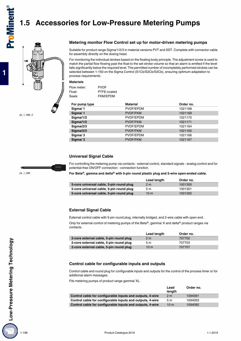
1.5 Accessories for Low-Pressure Metering PumpsLo
w-Pr
essu
re M
eter
ing Te
chno
logy
1
Metering monitor Flow Control set up for motor-driven metering pumpsSuitable for product range Sigma/1/2/3 in material versions PVT and SST. Complete with connector cable for assembly directly on the dosing head.For monitoring the individual strokes based on the floating body principle. The adjustment screw is used to match the partial flow flowing past the float to the set stroke volume so that an alarm is emitted if the level falls significantly below the required level. The permitted number of incompletely performed strokes can be selected between 1-150 on the Sigma Control (S1Cb/S2Cb/S3Cb), ensuring optimum adaptation to process requirements.Materials
Universal Signal CableFor controlling the metering pump via contacts - external control, standard signals - analog control and for potential-free ON/OFF connection - connection function.For Beta®, gamma and delta® with 5-pin round plastic plug and 5-wire open-ended cable.
External Signal CableExternal control cable with 5-pin round plug, internally bridged, and 2-wire cable with open end.Only for external control of metering pumps of the Beta®, gamma/ X and delta® product ranges via contacts.
Control cable for configurable inputs and outputsControl cable and round plug for configurable inputs and outputs for the control of the process timer or for additional alarm messages.Fits metering pumps of product range gamma/ XL.
pk_1_086_2
Flow meter: PVDFFloat: PTFE-coatedSeals: FKM/EPDM
For pump type Material Order no.Sigma/ 1 PVDF/EPDM 1021168Sigma/ 1 PVDF/FKM 1021169Sigma/1/2 PVDF/EPDM 1021170Sigma/1/2 PVDF/FKM 1021171Sigma/2/3 PVDF/EPDM 1021164Sigma/2/3 PVDF/FKM 1021165Sigma/ 3 PVDF/EPDM 1021166Sigma/ 3 PVDF/FKM 1021167
pk_1_085
Lead length Order no.5-core universal cable, 5-pin round plug 2 m 10013005-core universal cable, 5-pin round plug 5 m 10013015-core universal cable, 5-pin round plug 10 m 1001302
Lead length Order no.2-core external cable, 5-pin round plug 2 m 7077022-core external cable, 5-pin round plug 5 m 7077032-core external cable, 5-pin round plug 10 m 707707
Lead length
Order no.
Control cable for configurable inputs and outputs, 4-wire 2 m 1094091Control cable for configurable inputs and outputs, 4-wire 5 m 1094093Control cable for configurable inputs and outputs, 4-wire 10 m 1094092
1-198 Product Catalogue 2019 1.1.2019

Low-
Pres
sure
Met
ering
Tech
nolog
y
1.5 Accessories for Low-Pressure Metering Pumps
1
PROFIBUS® Adapter, Enclosure Rating IP 65
Reed cable with 3-pin round plug, PEFor Sigma metering pumps with 3-pin round plugs and a 3-core cable with an open end for level control.Suitable for Suction lance for motor-driven metering pumps* → 1-186
Level sensor cable for connection of a universal suction lance and a motor-driven metering pump For connection of the level switch of the universal suction lance for Sigma metering pumps or the higher-level control system (e.g. PLS).Suitable for PPE universal suction lance for motor-driven metering pumps → 1-185
P_AC_0245_SW
P_AC_0230_SW_1
P_AC_0239_SW
Fig. Order no.Y-adapter 2 x M12 x 1 male/female M12 x 1 male P_AC_0245_SW 1040956PROFIBUS® termination assembly, comprising a Y-plug and terminating resistance
M12 – 1040955
PROFIBUS® Y-adapter M 12 x 1 P_AC_0230_SW 1036621PROFIBUS® termination resistor, plug-in
M 12 x 1 P_AC_0239_SW 1036622
P_AC_0243_SWCable length Order no. m2 10303343 10303355 1030336
pk_1_126
P_AC_0243_SW
Cable length Fig. Order no. m
Round plug coupling for M12 3-pin round plug
2 pk_1_126 1040962
Round plug coupling for M12 3-pin round plug
5 pk_1_126 1040963
Round plug coupling for M12 open end
1.1 P_AC_0243_SW 1009873
Round plug coupling for M12 open end
5 P_AC_0243_SW 1022537
1.1.2019 Product Catalogue 2019 1-199

1.5 Accessories for Low-Pressure Metering PumpsLo
w-Pr
essu
re M
eter
ing Te
chno
logy
1
Diaphragm rupture indicatorTo trigger an alarm and switch off the metering pump in the event of diaphragm rupture. Consisting of PVC/PE level switch, clear acrylic storage tank, connecting sockets and connecting hose. Potential-free N/O switch, max. contact load 60 V AC, 300 mA, 18 W.Fits all types of Beta® and gamma/ L, Meta, Makro TZ and Makro/5Retrofitting is also possible
Diaphragm rupture indicator with optical sensorTo trigger an alarm and switch off the metering pump in the event of diaphragm rupture. Consisting of an optical sensor, which defines the changes to the refractive index when wetted with liquid. With connecting cable for connection to the pump.Fits pumps of the gamma/ X and gamma/ XL product rangeIt can also be retrofitted in the backplate.
HornHUW 55, 230 V, 50-60 Hz, 165 x 60 x 65, 85 phon, for use indoors(e.g. in connection with fault signalling relay)
Indicator lampRed for wall mounting 230 V, 50-60 Hz (e.g. in connection with fault signalling relay, relay control or clock generator relay)
1.5.5.2 Safety Equipment
pk_1_087
Order no.Diaphragm rupture indicator Beta, gamma/ L, Meta, Makro TZ 803640Diaphragm rupture indicator Makro/ 5 1019528
Order no.Diaphragm rupture indicator, assembled 1044477
pk_1_088
Order no.HUW 55 Horn 705002
Order no.Indicator lamp, red 914780
1-200 Product Catalogue 2019 1.1.2019

Low-
Pres
sure
Met
ering
Tech
nolog
y
1.5 Accessories for Low-Pressure Metering Pumps
1
Contact water meter for cold waterMulti-jet dry water meter, max. water temperature 50 °C.Horizontal fitting position, laterally tilted up to 90° and vertically rising and falling. With reed switch and 2 m cable with extruded round coupling for direct connection to the external contact input of the metering pump.Fits products ranges beta, gamma, delta and Sigma control.
Woltmann hybrid counter for cold waterMax. water temperature 50°C, ambient temperature –25°C to +55°C, battery life 15 years, degree of protection IP 68 Large measuring range Installation in every fitting position No calming sections needed Electronic counter with flow display Two electronic pulse outputs Issue of consumption and service data via M-bus
Performance data
Union assembly set with sealFor threaded water meter, brass.
1.5.5.3 Contact Water Meters for Use in Potable Water and Accessories
P_PNM_0033_SW
B1
H2
G
H1
L1
Threaded connector width
Connector thread
Continuousflow Q3
Overloadflow Q4
Minimumflow Q1
Installedlength L1
Weight Order no.
G m3/h m3/h l/h mm kgR 3/4 - DN 20 1 4 5 50 190 1.3 1093919R 1 - DN 25 1 1/4 10 12.5 125 260 2.1 1093921R 1 1/2 - DN 40 2 16 20 200 300 4.0 1093922R 2 - DN 50 2 1/2 25 31 310 300 4.0 1093923
P_AC_00273_SW
Overload flow 200 m3/hContinuous flow 160 m3/hTransition flow 0.2 m3/hMinimum flow 0.13 m3/hStart-up value 0.05 m3/hPressure lose at Q3 0.3 – 0.4 barChannel 3 Direction flagMax. contact rating 30 V DC, 30 mA
Nominal width
Constructionlength WS form
FlangeØ
Weight Pulse weightchannel 1
Pulse weightchannel 2
Pulse widthchannel 1
Pulse widthchannel 2
Order no.
mm mm kg l/lmp. l/lmp. ms msDN 80 300 201 16.0 1 100 5 100 1078183DN 100 360 228 21.3 1 100 5 100 1078184DN 150 500 286 43.5 10 1000 60 100 1078185
pk_1_098
Order no.R 3/4 G 1 359029R 1 G 1 1/4 801322R 1 1/4 G 1 1/2 – (turboDOS®) 359034R 1 1/2 G 2 359037R 2 G 2 1/2 359039
1.1.2019 Product Catalogue 2019 1-201

1.5 Accessories for Low-Pressure Metering PumpsLo
w-Pr
essu
re M
eter
ing Te
chno
logy
1
Complete threaded connector with seal and connector for injection valveFor threaded water meter with G 1/4 connector for injection valve, brass.
O-ring loaded injection valveFor use with threaded connectors on water meters.Short design for R 3/4 and R 1 threaded connectors, long design for R 1 1/2 and R 2 threaded connectors.Applications when using appropriate metering lines25 °C - max. operating pressure 16 bar45 °C - max. operating pressure 9 bar
P_AC_0249_SW
Order no.R 3/4 G 1 – 1/4 359030R 1 G 1 1/4 – 1/4 359032R 1 1/2 G 2 – 1/4 359038R 2 G 2 1/2 – 1/4 801321
P_AC_0008_SW
P_AC_0009_SW
Connector Material oØ x iØ Fig. Order no.mm
6/4 - G 1/4 short for hose PP/FKM 6 x 4 P_AC_0008_SW 9147546/4 - G 1/4 long for hose PP/FKM 6 x 4 P_AC_0009_SW 7411936/4 - G 1/4 short for hose PVC/FKM 6 x 4 P_AC_0008_SW 9145586/4 - G 1/4 long for hose PVC/FKM 6 x 4 P_AC_0009_SW 915091
1-202 Product Catalogue 2019 1.1.2019
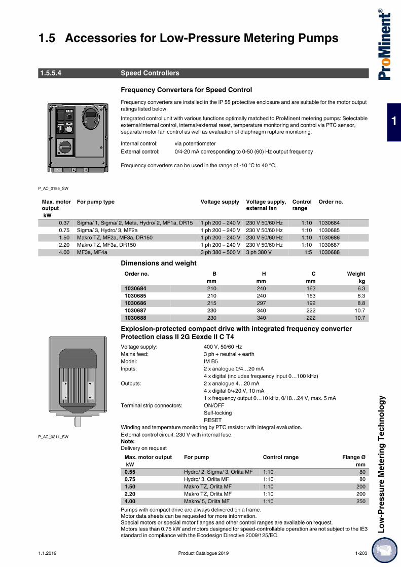
Low-
Pres
sure
Met
ering
Tech
nolog
y
1.5 Accessories for Low-Pressure Metering Pumps
1
Frequency Converters for Speed ControlFrequency converters are installed in the IP 55 protective enclosure and are suitable for the motor output ratings listed below.Integrated control unit with various functions optimally matched to ProMinent metering pumps: Selectable external/internal control, internal/external reset, temperature monitoring and control via PTC sensor, separate motor fan control as well as evaluation of diaphragm rupture monitoring.
Frequency converters can be used in the range of -10 °C to 40 °C.
Dimensions and weight
Explosion-protected compact drive with integrated frequency converter Protection class II 2G Eexde II C T4
Winding and temperature monitoring by PTC resistor with integral evaluation.External control circuit: 230 V with internal fuse.Note:Delivery on request
Pumps with compact drive are always delivered on a frame.Motor data sheets can be requested for more information.Special motors or special motor flanges and other control ranges are available on request.Motors less than 0.75 kW and motors designed for speed-controllable operation are not subject to the IE3 standard in compliance with the Ecodesign Directive 2009/125/EC.
1.5.5.4 Speed Controllers
P_AC_0185_SW
Internal control: via potentiometerExternal control: 0/4-20 mA corresponding to 0-50 (60) Hz output frequency
Max. motor output
For pump type Voltage supply Voltage supply, external fan
Control range
Order no.
kW0.37 Sigma/ 1, Sigma/ 2, Meta, Hydro/ 2, MF1a, DR15 1 ph 200 – 240 V 230 V 50/60 Hz 1:10 10306840.75 Sigma/ 3, Hydro/ 3, MF2a 1 ph 200 – 240 V 230 V 50/60 Hz 1:10 10306851.50 Makro TZ, MF2a, MF3a, DR150 1 ph 200 – 240 V 230 V 50/60 Hz 1:10 10306862.20 Makro TZ, MF3a, DR150 1 ph 200 – 240 V 230 V 50/60 Hz 1:10 10306874.00 MF3a, MF4a 3 ph 380 – 500 V 3 ph 380 V 1:5 1030688
Order no. B H C Weight mm mm mm kg
1030684 210 240 163 6.31030685 210 240 163 6.31030686 215 297 192 8.81030687 230 340 222 10.71030688 230 340 222 10.7
P_AC_0211_SW
Voltage supply: 400 V, 50/60 HzMains feed: 3 ph + neutral + earthModel: IM B5Inputs: 2 x analogue 0/4…20 mA
4 x digital (includes frequency input 0…100 kHz)Outputs: 2 x analogue 4…20 mA
4 x digital 0/+20 V, 10 mA1 x frequency output 0…10 kHz, 0/18…24 V, max. 5 mA
Terminal strip connectors: ON/OFFSelf-lockingRESET
Max. motor output For pump Control range Flange Ø kW mm0.55 Hydro/ 2, Sigma/ 3, Orlita MF 1:10 800.75 Hydro/ 3, Orlita MF 1:10 801.50 Makro TZ, Orlita MF 1:10 2002.20 Makro TZ, Orlita MF 1:10 2004.00 Makro/ 5, Orlita MF 1:10 250
1.1.2019 Product Catalogue 2019 1-203

1.5 Accessories for Low-Pressure Metering PumpsLo
w-Pr
essu
re M
eter
ing Te
chno
logy
1
For stainless steel liquid end. For assembly, including retrofitting, onto the liquid end. 10 mm diameter connectors for hot/cold chemicals with locking screws. Dimensions in mm. Outer diameter A, pitch circle diameter LK.
* Adapted to the design with the new multi-layer safety diaphragm.
1.5.5.5 Cooling/Heating Device for Diaphragm Metering Pumps
pk_2_059
Temperature -10 … 80 °C
For pump Ø A Ø LK Order no. mm mm
Sigma/ 1 FM 50/65* – – 1025500Sigma/ 1 FM 120* – – 1025501Sigma/ 2 FM 130* – – 1002178Sigma/ 2 FM 350* – – 1002179Sigma/ 3 FM 330* – – 1006455Sigma/ 3 FM 1000* – – 1006456Hydro/ 2/3 FMH 025/060 – – 1024743Hydro/ 3 FMH 150 – – 1040112Hydro/ 4 FMH 400 – – 1047700Meta, Makro TZ FM 130, FM 260 145 127 803751Meta, Makro TZ FM 530 180 164 803752Makro TZ FM 1500/2100 248 219 806005Makro/ 5 FM 4000 – – 1020683Makro TZ FMH 70/20 – – 1041263Makro/ 5 FMH 85/50 – – 1041261Makro/ 5 FMH 60/50 – – 1041260Makro/ 5 FMH 130/50 – – 1041262
1-204 Product Catalogue 2019 1.1.2019

Low-
Pres
sure
Met
ering
Tech
nolog
y
1.5 Accessories for Low-Pressure Metering Pumps
1
Anyone who works with chemicals, needs to store them safely. ProMinent® dosing tanks are tough and ideal for working with metering pumps.Useful capacity 35 – 1,500 lYour benefits Environmentally-friendly storage of liquid chemicals Robust and durable: stable design in UV-stabilised PE (polyethylene) Scale for litres and US gallons Simple to install: sintered threaded sockets for fixing ProMinent metering pumps and stirrers on storage
tanks Safe storage: A screw cover closes safely (push-on lid for 35-litre storage tank) Flat sides to secure the storage tank. Standard colours: natural, black, blue, yellow and red.
Natural Coloured/Transparent PE Dosing Tank
Natural Coloured/Transparent PE Dosing TankDesigned for the installation of a manually operated or electric stirrer.
Dosing tanks without ProMinent logo are available on request.
1.5.6 PE Metering Tanks and Collecting Pans
1.5.6.1 Dosing Tanks
PE storage tanks produced in a rotation process. They can be enhanced with ProMinent® metering pumps, suction lances and stirrers. The stackable PE collection pans are available in matching sizes.
pk_3_0001_1a
Usable capacity
D H Threaded bush for metering pumps
Weight Order no.
l mm mm kg35 350 485 without threaded sockets 3.5 79199360 410 590 gamma/ X, Beta® 5.0 791994100 500 760 alpha, Beta®, gamma/ X 7.0 1001490140 500 860 alpha, Beta®, gamma/ X 9.5 791995250 650 1,100 alpha, Beta®, gamma/ X, Sigma/
1/ 2/ 3, delta®17.5 1023175
500 820 1,230 2 x gamma/ X, 2 x Sigma/ 1, 2, 3, 2 x delta®, 2 x Beta®
32.0 791997
1,000 1,070 1,260 2 x gamma/ X, 2 x Sigma/ 1, 2, 3, 2 x delta®, 2 x Beta®
51.0 1010909
1,500 1,150 1,735 2 x gamma/ X, 2 x Sigma/ 1, 2, 3, 2 x delta®, 2 x Beta®
80.0 1060975
Usable capacity with an opening for Order no. l60 manually operated stirrer 79210460 electric stirrer 792105100 manually operated stirrer 1002034100 electric stirrer 1002033140 manually operated stirrer 792106140 electric stirrer 792107250 manually operated stirrer 792108250 electric stirrer 792109500 manually operated stirrer 792110500 electric stirrer 7921111,000 manually operated stirrer 10109101,000 electric stirrer 1010911
The 35 – 1,000-litre storage tank have an R 3/4" threaded sleeve (1,500 l: R 1 1/4") for drainage that can be drilled to Ø 10 mm on site if required. A PE R 3/4" sealing stopper (1,500 l: R 1 1/4") with a seal is screwed in.
1.1.2019 Product Catalogue 2019 1-205

1.5 Accessories for Low-Pressure Metering PumpsLo
w-Pr
essu
re M
eter
ing Te
chno
logy
1
Black PE Dosing TankFor light sensitive media.
Blue PE Dosing Tank
Yellow PE Dosing Tank
Red PE Dosing Tank
Dosing tanks without ProMinent® logo are available on request.
pk_3_001_1
Usable capacity Order no. l35 79199860 791999100 1001322140 792000250 1023176500 7920021,000 10109121,500 1060976
Usable capacity Order no. l35 100381260 1003813100 1003814140 1003815250 1023177500 10038171,000 10109131,500 1060977
Usable capacity Order no. l35 100381860 1003819100 1003820140 1003821250 1023178500 10038231,000 10109141,500 1060978
Usable capacity Order no. l35 100382460 1003825100 1003826140 1003827250 1023179500 10038291,000 10109151,500 1060979
1-206 Product Catalogue 2019 1.1.2019

Low-
Pres
sure
Met
ering
Tech
nolog
y
1.5 Accessories for Low-Pressure Metering Pumps
1
Natural/transparent PE dosing tank with flat mounting surface
Your benefits "Natural/transparent PE dosing tank" design without sintered threaded socket Level mounting surface for the installation of metering pumps on the storage tank Additional installation of a manual or electric stirrer is possible
Made of UV-stabilised polyethylene in a stackable design with ProMinent® logo. 2 flat sides for fixing the collecting pan.Colourless/Transparent PE Stackable Collecting Pans
Black PE Stackable Collecting Pans
Blue PE Stackable Collecting Pans
P_DO_0022_SW1
Usable capacity
D H Threaded bush for meter-ing pumps
Weight Order no.
l mm mm kg35 350 485 without threaded sockets 3.5 79199360 410 590 without threaded sockets 5.0 1061060100 500 760 without threaded sockets 7.0 1008599250 650 1,100 without threaded sockets 17.5 1061061
1.5.6.2 PE Stackable Collecting Pans for Dosing Tanks
pk_3_019
Usable capacity
D2 D1 H Weight Order no.
l mm mm mm kg35 565 507 220 3.0 101087960 680 607 270 4.3 1010880100 802 727 320 6.5 1010881140 811 727 370 7.0 1010882250 917 807 520 11.0 1010883500 1,155 1,009 670 16.0 1010884
Usable capacity
D2 D1 H Weight Order no.
l mm mm mm kg35 565 507 220 3.0 101088560 680 607 270 4.3 1010886100 802 727 320 6.5 1010887140 811 727 370 7.0 1010888250 917 807 520 11.0 1010889500 1,155 1,009 670 16.0 1010890
Usable capacity
D2 D1 H Weight Order no.
l mm mm mm kg35 565 507 220 3.0 101089160 680 607 270 4.3 1010892100 802 727 320 6.5 1010893140 811 727 370 7.0 1010894250 917 807 520 11.0 1010895500 1,155 1,009 670 16.0 1010896
1.1.2019 Product Catalogue 2019 1-207
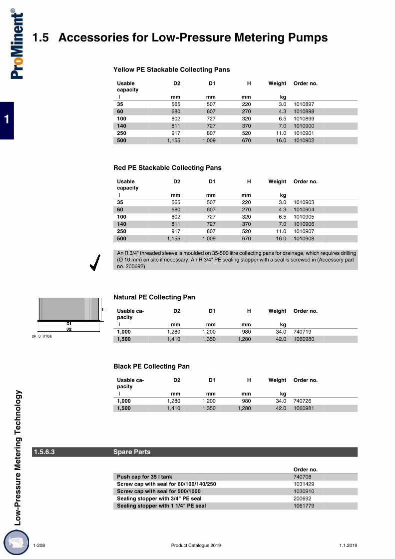
1.5 Accessories for Low-Pressure Metering PumpsLo
w-Pr
essu
re M
eter
ing Te
chno
logy
1
Yellow PE Stackable Collecting Pans
Red PE Stackable Collecting Pans
Natural PE Collecting Pan
Black PE Collecting Pan
Usable capacity
D2 D1 H Weight Order no.
l mm mm mm kg35 565 507 220 3.0 101089760 680 607 270 4.3 1010898100 802 727 320 6.5 1010899140 811 727 370 7.0 1010900250 917 807 520 11.0 1010901500 1,155 1,009 670 16.0 1010902
Usable capacity
D2 D1 H Weight Order no.
l mm mm mm kg35 565 507 220 3.0 101090360 680 607 270 4.3 1010904100 802 727 320 6.5 1010905140 811 727 370 7.0 1010906250 917 807 520 11.0 1010907500 1,155 1,009 670 16.0 1010908
An R 3/4" threaded sleeve is moulded on 35-500 litre collecting pans for drainage, which requires drilling (Ø 10 mm) on site if necessary. An R 3/4" PE sealing stopper with a seal is screwed in (Accessory part no. 200692).
pk_3_018a
Usable ca-pacity
D2 D1 H Weight Order no.
l mm mm mm kg1,000 1,280 1,200 980 34.0 7407191,500 1,410 1,350 1,280 42.0 1060980
Usable ca-pacity
D2 D1 H Weight Order no.
l mm mm mm kg1,000 1,280 1,200 980 34.0 7407261,500 1,410 1,350 1,280 42.0 1060981
1.5.6.3 Spare Parts
Order no.Push cap for 35 l tank 740708Screw cap with seal for 60/100/140/250 1031429Screw cap with seal for 500/1000 1030910Sealing stopper with 3/4" PE seal 200692Sealing stopper with 1 1/4" PE seal 1061779
1-208 Product Catalogue 2019 1.1.2019
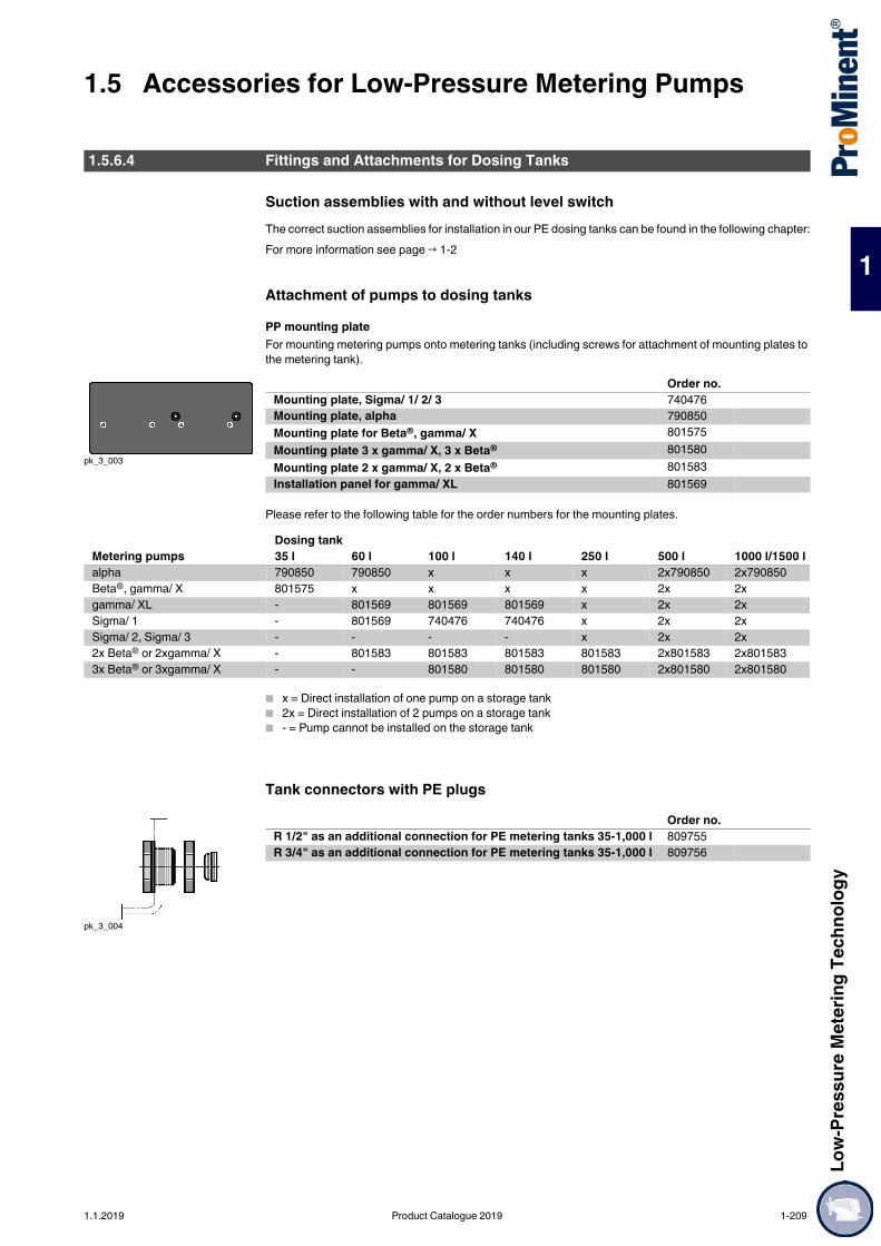
Low-
Pres
sure
Met
ering
Tech
nolog
y
1.5 Accessories for Low-Pressure Metering Pumps
1
Suction assemblies with and without level switchThe correct suction assemblies for installation in our PE dosing tanks can be found in the following chapter:For more information see page → 1-2
Attachment of pumps to dosing tanksPP mounting plateFor mounting metering pumps onto metering tanks (including screws for attachment of mounting plates to the metering tank).
Please refer to the following table for the order numbers for the mounting plates.
x = Direct installation of one pump on a storage tank 2x = Direct installation of 2 pumps on a storage tank - = Pump cannot be installed on the storage tank
Tank connectors with PE plugs
1.5.6.4 Fittings and Attachments for Dosing Tanks
pk_3_003
Order no.Mounting plate, Sigma/ 1/ 2/ 3 740476Mounting plate, alpha 790850Mounting plate for Beta®, gamma/ X 801575Mounting plate 3 x gamma/ X, 3 x Beta® 801580Mounting plate 2 x gamma/ X, 2 x Beta® 801583Installation panel for gamma/ XL 801569
Dosing tankMetering pumps 35 l 60 l 100 l 140 l 250 l 500 l 1000 l/1500 lalpha 790850 790850 x x x 2x790850 2x790850Beta®, gamma/ X 801575 x x x x 2x 2xgamma/ XL - 801569 801569 801569 x 2x 2xSigma/ 1 - 801569 740476 740476 x 2x 2xSigma/ 2, Sigma/ 3 - - - - x 2x 2x2x Beta® or 2xgamma/ X - 801583 801583 801583 801583 2x801583 2x8015833x Beta® or 3xgamma/ X - - 801580 801580 801580 2x801580 2x801580
pk_3_004
Order no.R 1/2" as an additional connection for PE metering tanks 35-1,000 l 809755R 3/4" as an additional connection for PE metering tanks 35-1,000 l 809756
1.1.2019 Product Catalogue 2019 1-209

1.5 Accessories for Low-Pressure Metering PumpsLo
w-Pr
essu
re M
eter
ing Te
chno
logy
1
PP discharge tap
PVC discharge tap
Screw cap lock
pk_3_005
Order no.For metering tanks with d 20, Ø 20 mm hose nozzle and 3/4’’ nipple for direct connection to the threaded connector on the tank.
809714
Order no.For metering tanks with d 16, Ø 16 mm hose nozzle and 3/4’’ nipple for direct connection to the threaded connector on the tank.
809745
Order no.Lock with key for screw cap 200683
1-210 Product Catalogue 2019 1.1.2019

Low-
Pres
sure
Met
ering
Tech
nolog
y
1.5 Accessories for Low-Pressure Metering Pumps
1
StirrersPP Hand mixerFully assembled.
PP Hand stirrerWith crank, fully assembled
Timer with digital clock
Stirrers should only be operated via the motor protection switch!
pk_3_009
A Ø Order no. mm mm
for 35 and 60 l tanks 515 90 741118for 100 and 140 l tanks 715 90 741119for 250 and 500 l tanks 1,040 130 741120
pk_3_007
A B Order no. mm mm
for 60 l tanks 670 465 914701for 100 l tanks 855 650 914738for 140 l tanks 965 765 914702for 250 and 500 l tanks 1,175 965 914703for 1000 l tanks 1,240 1,040 914705
pk_3_010_1
Order no.In plastic housing for the control of a stirrer or a metering pump, 230 V, 50 Hz, max. 6A, IP 65. Day and week programs, shortest switching time 1 min. with 2 m power cable and euro plug.
1005561
1.1.2019 Product Catalogue 2019 1-211

1.5 Accessories for Low-Pressure Metering PumpsLo
w-Pr
essu
re M
eter
ing Te
chno
logy
1
Electric stirrers for dosing tanksFor the batching and mixing of liquids up to max. 500 mPas viscosity. Intermittent operation using timer recommended. Wide-range motor with insulation class F, insulated for use in hot climates Stainless steel or plastic-coated shaft Polypropylene propeller Provide a motor protection switch for all stirrers. Not suitable for gaseous media
Stainless steel electric stirrer
Chemical resistant electric stirrer
Technical Data
1.5.7Product Catalogue 2019. 1.5.8www.prominent.com
For tank Poweruptake
Shaft Propeller Weight Order no.
W kg60 l 20 1.4571 PP 2.9 818576100 l 180 1.4571 PP 3.0 1001566140 l 180 1.4571 PP 7.3 791502250 l 180 1.4571 PP 7.3 791503500 l 250 1.4571 PP 8.5 7915041000 l 750 1.4571 PVDF 18.0 7914581500 l 550 1.4535 PVDF 22.0 1078647
pk_3_008
Size A B Ø D Ø LK Ø F60 195 490 115 100 70100 200 675 160 130 70140 200 780 160 130 70250 200 950 160 130 70500 200 950 160 130 701000 230 1190 200 165 1301500 282 1400 200 165 175
For tank Poweruptake
Shaft Propeller Weight Order no.
W kg60 l 20 1.4571/PVDF PP 2.9 818577100 l 180 1.4571/PVDF PP 3.0 1002035140 l 180 1.4571/PVDF PP 7.3 791454250 l 180 1.4571/PVDF PP 7.3 791455500 l 250 1.4571/PVDF PP 8.5 7914561000 l 750 1.4571/PVDF PVDF 18.0 7914571500 l 550 Steel/PE PVDF 22.0 1078646
For tank Poweruptake
Voltage (50 Hz) Nominal current (50 Hz)
Speed (50 Hz) Enclosure rat-ing
W60 l 20 1 pH, 230 V 0,38 A 1400 IP55100 l 180 1 pH, 230 V 1,9 A 1440 IP55140 l 180 1 pH, 230 V 1,9 A 1440 IP55250 l 180 1 pH, 230 V 1,9 A 1440 IP55500 l 250 1 pH, 230 V 1,8 A 1440 IP551000 l 750 3 pH, 230/400 V 2,96/1,71 A 1440 IP551500 l 550 3 pH, 230/400 V 4,1/2,3 A 750 IP55
1-212 Product Catalogue 2019 1.1.2019

Low-
Pres
sure
Met
ering
Tech
nolog
y
1.6 Metering Systems
1
1.6Metering Systems
Choose from a range of different components and adapt the metering system to your requirements.
Two hydraulic connection points guarantee simple installation of the metering system. The ready mounted system consists of components that have been perfectly matched to each other to ensure problem-free operation. You obtain a complete system. Individually configure your metering system at the time of ordering. A simple selection system makes ordering easy and guarantees maximum efficiency even at the time of ordering.Your benefits One to three metering pumps mounted on a storage tank, ready for connection with all the necessary
accessories Short delivery time Outstanding value for money Compact construction Fast commissioning Versatile use All the components are perfectly matched to each other and fit precisely Environmentally-friendly handling of chemicals
Technical Details Dosing tank: PE, various colours, 35 – 1,000 litres Collecting pan: PE, various colours, 35 – 1,000 litres Lock for screw top Hand mixer / stirrer: PP, PVDF or stainless steel, various outputs Suction assembly: PP, PVC, various connectors Level switch for suction assembly: 2 -stage Drain tap: PP, PVC, with ball valve Metering pump: alpha, Beta®, gamma/ X, Sigma/ 1, Sigma/ 2, Sigma/ 3
Field of applicationTreatment of cooling, process and swimming pool water
Selectable components
1.6.1 Metering System DULCODOS® eco (DSBa)
For storing and metering liquid chemicals Use a selection guide (identity code) to quickly and flexibly adapt your metering system to your metering task.
pk_3_033
pk_3_034
ProMinent metering systems with PE storage tanks can be selected and ordered with the help of an identity code system. First select the metering pump using the separate pump identity code.
1. PE dosing tank (35 – 1,000 litres)2. Stackable collecting pans (35 – 1,000 litres)3. Lock for tank screw top4. Hand mixer/stirrer (*)5. Suction assembly6. Level switch for suction assembly7. Drain tap for storage tank (*)8. Order metering pump (*) separately
(Order the pump separately due to the large number of possible pumps that can be installed on storage tanks. Use the identity code for the pump you require.)
* These components are ready for subsequent installation, but are supplied separately to avoid damage in transit. Customers should fully install the system on site.
1.1.2019 Product Catalogue 2019 1-213

1.6 Metering SystemsLo
w-Pr
essu
re M
eter
ing Te
chno
logy
1
Identity Code Ordering System for Metering System with Storage Tank, 35 litres
DSBa PE tank0035N 35 l PE metering tank, neutral colour0035S 35 l PE metering tank, black0035B 35 l PE metering tank, blue0035G 35 l PE metering tank, yellow0035R 35 l PE metering tank, red
Collecting pan0 without collecting pan1 with collecting pan, neutral colour2 with collecting pan, coloured (the same colour as the tank)
Version0 with ProMinent® Logo
Lock for tank screw top0 without lock
Hand mixer, stirrer0 noneA with PP hand mixer
Metering pump mounting0 without pumpD for alphaE for Beta®, gamma/ X
Suction assembly selection0 without suction assembly1 suction assembly with 6x4 suction hose2 suction assembly with 8x5 suction hose3 suction assembly with 12x9 suction hose
Suction assembly material0 none1 PVC2 PP
Suction assembly float switch0 without float switch1 2-stage, round plug, (6 x 4, 8 x 5,12 x 9) for Beta®, gamma/ X
Accessories - discharge tap for tank0 without accessories1 with ball valve PVC, hose grommet d16 **2 with ball valve PP, hose grommet d20 **
Calibration assembly0 none
Info - pump* e.g. BT4 1005 PPE 300AA000
* Please enter the Identity code of the selected pump** Ball valve can only be selected if the metering station is ordered without drip pan.*** Metering gauge can only be selected if the metering station is ordered without drip pan and without
suction fitting.
1-214 Product Catalogue 2019 1.1.2019

Low-
Pres
sure
Met
ering
Tech
nolog
y
1.6 Metering Systems
1
Identity Code Ordering System for Metering System with Storage Tank, 60 litres
DSBa PE tank0060N 60 l PE metering tank, neutral colour0060S 60 l PE metering tank, black0060B 60 l PE metering tank, blue0060G 60 l PE metering tank, yellow0060R 60 l PE metering tank, red
Collecting pan0 without collecting pan1 with collecting pan, neutral colour2 with collecting pan, coloured (the same colour as the tank)
Version0 with ProMinent® Logo
Lock for tank screw top1 with lock
Hand mixer, stirrer0 noneA with PP hand mixerB with PP hand stirrerH with stainless steel 0.02 kW electric stirrerP with PVDF 0.02 kW electric stirrer
Metering pump mounting0 without pumpA for Beta®, gamma/ XD for alphaF for Sigma/ 1P for delta®
Suction assembly selection0 without suction assembly1 suction assembly with 6x4 suction hose2 suction assembly with 8x5 suction hose3 suction assembly with 12x9 suction hose4 suction assembly DN 105 suction assembly DN 15
Suction assembly material0 none1 PVC2 PP
Suction assembly float switch0 without float switch1 2-stage, round plug, (6 x 4, 8 x 5,12 x 9) for Beta®, gamma/ X, delta®
2 2-stage, round plug, (DN 10-32) for Sigma/ 1/ 2/ 3, delta®
Accessories - discharge tap for tank0 without accessories1 with ball valve PVC, hose grommet d16 **2 with ball valve PP, hose grommet d20 **
Calibration assembly0 none
Info - pump* e.g. GMXa 0414 PVT 20000UA
* Please enter the Identity code of the selected pump** Ball valve can only be selected if the metering station is ordered without drip pan.*** Metering gauge can only be selected if the metering station is ordered without drip pan and without
suction fitting.
1.1.2019 Product Catalogue 2019 1-215

1.6 Metering SystemsLo
w-Pr
essu
re M
eter
ing Te
chno
logy
1
Identity Code Ordering System for Metering System with Storage Tank, 100 litres
DSBa PE tank0100N 100 l PE metering tank, neutral colour0100S 100 l PE metering tank, black0100B 100 l PE metering tank, blue0100G 100 l PE metering tank, yellow0100R 100 l PE metering tank, red
Collecting pan0 without collecting pan1 with collecting pan, neutral colour2 with collecting pan, coloured (the same colour as the tank)
Version0 with ProMinent® Logo
Lock for tank screw top1 with lock
Hand mixer, stirrer0 noneA with PP hand mixerC with PP hand stirrerI with stainless steel 0.18 kW electric stirrerR with PVDF 0.18 kW electric stirrer
Metering pump mounting0 without pumpA for Beta®, gamma/ XL for Sigma/ 1N for alphaP for delta®
Suction assembly selection0 without suction assembly1 suction assembly with 6x4 suction hose2 suction assembly with 8x5 suction hose3 suction assembly with 12x9 suction hose4 suction assembly DN 105 suction assembly DN 15
Suction assembly material0 none1 PVC2 PP
Suction assembly float switch0 without float switch1 2-stage, round plug, (6 x 4, 8 x 5,12 x 9) for Beta®, gamma/ X, delta®
2 2-stage, round plug, (DN 10-32) for Sigma/ 1/ 2/ 3, delta®
Accessories - discharge tap for tank0 without accessories1 with ball valve PVC, hose grommet d16 **2 with ball valve PP, hose grommet d20 **
Calibration assembly0 none
Info - pump* e.g. GMXa 0414 PVT 20000UA
* Please enter the Identity code of the selected pump** Ball valve can only be selected if the metering station is ordered without drip pan.*** Metering gauge can only be selected if the metering station is ordered without drip pan and without
suction fitting.
1-216 Product Catalogue 2019 1.1.2019

Low-
Pres
sure
Met
ering
Tech
nolog
y
1.6 Metering Systems
1
Identity Code Ordering System for Metering System with Storage Tank, 140 litres
DSBa PE tank0140N 140 l PE metering tank, neutral colour0140S 140 l PE metering tank, black0140B 140 l PE metering tank, blue0140G 140 l PE metering tank, yellow0140R 140 l PE metering tank, red
Collecting pan0 without collecting pan1 with collecting pan, neutral colour2 with collecting pan, coloured (the same colour as the tank)
Version0 with ProMinent® Logo
Lock for tank screw top1 with lock
Hand mixer, stirrer0 noneA with PP hand mixerD with PP hand stirrerK with stainless steel 0.18 kW electric stirrerS with PVDF 0.18 kW electric stirrer
Metering pump mounting0 without pumpA for Beta®, gamma/ XD for alphaH for Sigma/ 1P for delta®
Suction assembly selection0 without suction assembly1 suction assembly with 6x4 suction hose2 suction assembly with 8x5 suction hose3 suction assembly with 12x9 suction hose4 suction assembly DN 105 suction assembly DN 15
Suction assembly material0 none1 PVC2 PP
Suction assembly float switch0 without float switch1 2-stage, round plug, (6 x 4, 8 x 5,12 x 9) for Beta®, gamma/ X, delta®
2 2-stage, round plug, (DN 10-32) for Sigma/ 1/ 2/ 3, delta®
Accessories - discharge tap for tank0 without accessories1 with ball valve PVC, hose grommet d16 **2 with ball valve PP, hose grommet d20 **
Calibration assembly0 none
Info - pump* e.g. GMXa 0414 PVT 20000UA
* Please enter the Identity code of the selected pump** Ball valve can only be selected if the metering station is ordered without drip pan.*** Metering gauge can only be selected if the metering station is ordered without drip pan and without
suction fitting.
1.1.2019 Product Catalogue 2019 1-217

1.6 Metering SystemsLo
w-Pr
essu
re M
eter
ing Te
chno
logy
1
Identity Code Ordering System for Metering System with Storage Tank, 250 litres
DSBa PE tank0250N 250 l PE metering tank, neutral colour0250S 250 l PE metering tank, black0250B 250 l PE metering tank, blue0250G 250 l PE metering tank, yellow0250R 250 l PE metering tank, red
Collecting pan0 without collecting pan1 with collecting pan, neutral colour2 with collecting pan, coloured (the same colour as the tank)
Version0 with ProMinent® Logo
Lock for tank screw top1 with lock
Hand mixer, stirrer0 noneA with PP hand mixerE with PP hand stirrerL with stainless steel 0.18 kW electric stirrerT with electric stirrer PVDF 0.18 kW
Metering pump mounting0 without pumpA for Beta®, gamma/ XB for Sigma/ 2/ 3C for Sigma/ 1N for alphaP for delta®
Suction assembly selection0 without suction assembly1 suction assembly with 6x4 suction hose2 suction assembly with 8x5 suction hose3 suction assembly with 12x9 suction hose4 suction assembly DN 105 suction assembly DN 157 suction assembly DN 258 suction assembly DN 32
Suction assembly material0 none1 PVC2 PP
Suction assembly float switch0 without float switch1 2-stage, round plug, (6 x 4, 8 x 5,12 x 9) for Beta®, gamma/ X, delta®
2 2-stage, round plug, (DN 10-32) for Sigma/ 1/ 2/ 3, delta®
Accessories - discharge tap for tank0 without accessories1 with ball valve PVC, hose grommet d16 **2 with ball valve PP, hose grommet d20 **
Calibration assembly0 none
Info - pump* e.g. GMXa 0414 PVT 20000UA
* Please enter the Identity code of the selected pump** Ball valve can only be selected if the metering station is ordered without drip pan.*** Metering gauge can only be selected if the metering station is ordered without drip pan and without
suction fitting.
1-218 Product Catalogue 2019 1.1.2019

Low-
Pres
sure
Met
ering
Tech
nolog
y
1.6 Metering Systems
1
Identity Code Ordering System for Metering System with Storage Tank, 500 litres
DSBa PE tank0500N 500 l PE metering tank, neutral colour0500S 500 l PE metering tank, black0500B 500 l PE metering tank, blue0500G 500 l PE metering tank, yellow 0500R 500 l PE metering tank, red
Collecting pan0 without collecting pan1 with collecting pan, neutral colour2 with collecting pan, coloured (the same colour as the tank)
Version0 with ProMinent® Logo
Lock for tank screw top1 with lock
Hand mixer, stirrer0 noneA with PP hand mixerF with PP hand stirrerM with stainless steel 0.25 kW electric stirrerU with PVDF 0.25 kW electric stirrer
Metering pump mounting0 without pumpA for Beta®, gamma/ XC for Sigma/ 1, delta®
D for alphaJ for Sigma/ 2/ 3P for delta®
Suction assembly selection0 without suction assembly1 suction assembly with 6x4 suction hose2 suction assembly with 8x5 suction hose3 suction assembly with 12x9 suction hose4 suction assembly DN 105 suction assembly DN 157 suction assembly DN 258 suction assembly DN 32
Suction assembly material0 none1 PVC2 PP
Suction assembly float switch0 without float switch1 2-stage, round plug, (6 x 4, 8 x 5,12 x 9) for Beta®, gamma/ X, delta®
2 2-stage, round plug, (DN 10-32) for Sigma/ 1/ 2/ 3, delta®
Accessories - discharge tap for tank0 without accessories1 with ball valve PVC, hose grommet d16 **2 with ball valve PP, hose grommet d20 **
Calibration assembly0 none
Info - pump* e.g. GMXa 0414 PVT 20000UA
* Please enter the Identity code of the selected pump** Ball valve can only be selected if the metering station is ordered without drip pan.*** Metering gauge can only be selected if the metering station is ordered without drip pan and without
suction fitting.
1.1.2019 Product Catalogue 2019 1-219

1.6 Metering SystemsLo
w-Pr
essu
re M
eter
ing Te
chno
logy
1
Identity Code Ordering System for Metering System with Storage Tank, 1000 litres
DSBa PE tank1000N 1000 l PE metering tank, neutral colour1000S 1000 l PE metering tank, black1000B 1000 l PE metering tank, blue 1000G 1000 l PE metering tank, yellow 1000R 1000 l PE metering tank, red
Collecting pan0 without collecting pan1 with collecting pan, neutral colour2 with collecting pan, black
Version0 with ProMinent® Logo
Lock for tank screw top1 with lock
Hand mixer, stirrer0 noneG with hand mixer PPN with stainless steel 0.75 kW electric stirrerW with PVDF 0.75 kW electric stirrer
Metering pump mounting0 without pumpA for Beta®, gamma/ XB for Sigma/ 2/ 3C for Sigma/ 1D for alphaP for delta®
Suction assembly selection0 without suction assembly1 suction assembly with 6x4 suction hose2 suction assembly with 8x5 suction hose3 suction assembly with 12x9 suction hose4 suction assembly DN 105 suction assembly DN 157 suction assembly DN 258 suction assembly DN 32
Suction assembly material0 none1 PVC2 PP
Suction assembly float switch0 without float switch1 2-stage, round plug, (6x4, 8x5, 12x9) for Beta®, gamma/ X, delta®
2 2-stage, round plug, (DN 10-32) for Sigma/ 1/ 2/ 3, delta®
Accessories - discharge tap for tank0 without accessories1 with ball valve PVC, hose grommet d16 **2 with ball valve PP, hose grommet d20 **
Calibration assembly0 none
Info - pump* e.g. GMXa 0414 PVT 20000UA
* Please enter the Identity code of the selected pump** Ball valve can only be selected if the metering station is ordered without drip pan.*** Metering gauge can only be selected if the metering station is ordered without drip pan and without
suction fitting.
1-220 Product Catalogue 2019 1.1.2019

Low-
Pres
sure
Met
ering
Tech
nolog
y
1.6 Metering Systems
1
Liquid chemicals are metered conveniently, cost-effectively and reliablyPump volume depending on the selected pump up to 75 l/h, back pressure 10 – 2 bar
Metering is dependent on the metering pump. Components, such as pipes, relief valves and electrics – indispensable, but scarcely variable – ensure the reliable operation of the system. That is why we have pre-configured the new metering system DULCODOS® universal with these standards. The benefits for you: low costs, fast delivery, simple commissioning.Naturally you have a choice here as well: Should it be the solenoid-driven metering pump Beta® 4 or 5, delta® or gamma/ X? Should the pipes and seals be made of PP/FKM or PVC/EPDM? And do you need one or two points of injection with one or two pumps?The novel valve block gives every metering system a clearly arranged structure. Every system is equipped with two relief valves, a collecting pan with leakage sensor and a calibration tank for controlled metering for complete operational safety.
Your benefits Reliable and precise metering of liquid chemicals with proven solenoid-driven metering pumps Safe operation thanks to relief valves and collecting pan Stable installation frame rotationally sintered from a single piece Systems with 1 or 2 pumps and 1 or 2 points of injection Calibration unit with priming function for controlled metering Optional: Pulsation dampener, spray guard
Technical Details ProMinent solenoid-driven metering pumps Beta® 4/5, delta® or gamma/ X Dimensions: 1,700 x 1,200 x 635 mm (H x W x D) Material combinations: PP/FKM or PVC/EPDM (note compatibility with the feed chemical) Relief valves to protect the pipework Manometer Collecting pan with leakage sensor Flushing connectors Terminal box with master switch Assembly frame available in 4 standard colours
Field of applicationMetering of liquid chemicals, e.g. cooling water treatment Waste water and process water treatment Paper industry
Type selection
1.6.2 Metering System DULCODOS® universal (DSUa)
The metering system DULCODOS® universal combines carefully selected standard components with the solenoid-driven metering pump you have selected. This is your convenient method for the reliable metering of liquid chemicals – and is available cost-effectively and extremely quickly thanks to the preconfigured modules.
P_DST_0004_SW_3DDULCODOS® Universal, type 1
P_DST_0006_SW_3DDULCODOS® Universal, type 2
P_DST_0005_SW_3DDULCODOS® Universal, type 3
Metering pumps
Points of injection
Material combinations Hose materials
Type 1 1 1 PVC/EPDM or PP/FKM PTFEType 2 2 1 PVC/EPDM or PP/FKM PTFEType 3 2 2 PVC/EPDM or PP/FKM PTFE
1.1.2019 Product Catalogue 2019 1-221
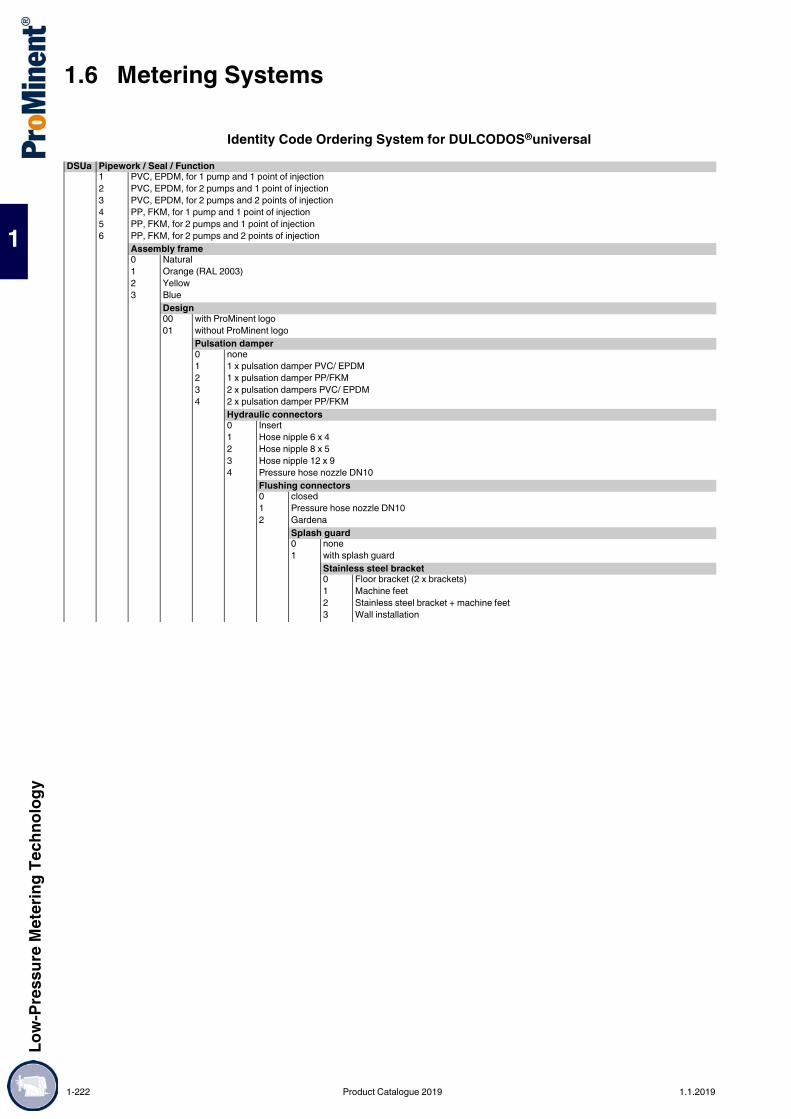
1.6 Metering SystemsLo
w-Pr
essu
re M
eter
ing Te
chno
logy
1
Identity Code Ordering System for DULCODOS®universalDSUa Pipework / Seal / Function
1 PVC, EPDM, for 1 pump and 1 point of injection2 PVC, EPDM, for 2 pumps and 1 point of injection3 PVC, EPDM, for 2 pumps and 2 points of injection4 PP, FKM, for 1 pump and 1 point of injection5 PP, FKM, for 2 pumps and 1 point of injection6 PP, FKM, for 2 pumps and 2 points of injection
Assembly frame0 Natural1 Orange (RAL 2003)2 Yellow3 Blue
Design00 with ProMinent logo01 without ProMinent logo
Pulsation damper0 none1 1 x pulsation damper PVC/ EPDM2 1 x pulsation damper PP/FKM3 2 x pulsation dampers PVC/ EPDM4 2 x pulsation damper PP/FKM
Hydraulic connectors0 Insert1 Hose nipple 6 x 42 Hose nipple 8 x 53 Hose nipple 12 x 94 Pressure hose nozzle DN10
Flushing connectors0 closed1 Pressure hose nozzle DN102 Gardena
Splash guard0 none1 with splash guard
Stainless steel bracket0 Floor bracket (2 x brackets)1 Machine feet2 Stainless steel bracket + machine feet3 Wall installation
1-222 Product Catalogue 2019 1.1.2019

Low-
Pres
sure
Met
ering
Tech
nolog
y
1.6 Metering Systems
1
Pump 100 without pump41 10 bar / 0.74 l/h, BT4b 1000 PVT2000U1100000, 6 x 442 16 bar / 2.2 l/h, BT4b 1602 PVT2000U1100000, 6 x 443 16 bar / 3.60 l/h, BT4b 1604 PVT2000U1100000, 6 x 444 7 bar / 7.10 l/h, BT4b 0708 PVT2000U1100000, 8 x 545 4 bar / 12.30 l/h, BT4b 0413 PVT2000U1100000, 8 x 546 2 bar / 19.00 l/h, BT4b 0220 PVT2000U1100000, 12 x 951 10 bar / 6.80 l/h, BT5b 1008 PVT2000U1100000, 8 x 552 7 bar / 11.0 l/h, BT5b 0713 PVT2000U1100000, 8 x 553 4 bar / 17.10 l/h, BT5b 0420 PVT2000U1100000, 12 x 954 2 bar / 32.00 l/h, BT5b 0232 NPE2000U1100000, 12 x 9D1 16 bar / 11.3 l/h, DLTa 1612 PVT2000U11030EN0, 8 x 5D2 10 bar / 19.1 l/h, DLTa 1020 PVT2000U11030EN0, 12 x 9D3 7 bar / 29.2 l/h, DLTa 0730 PVT2000U11030EN0, 12 x 9D4 4 bar / 49.0 l/h, DLTa 0450 PVT2000U11030EN0, DN10D5 2 bar / 75.0 l/h, DLTa 0280 PVT2000U11030EN0, DN10X1 16 bar / 3.6 l/h, GMXa 1604 PVT20000U110300EN, 6 x 4X2 7 bar / 7.6 l/h, GMXa 0708 PVT20000U110300EN, 8 x 5X3 10 bar / 9.0 l/h, GMXa 1009 PVT20000U110300EN, 8 x 5X4 4 bar / 13.5 l/h, GMXa 0414 PVT20000U110300EN, 8 x 5X5 7 bar / 14.5 l/h, GMXa 0715 PVT20000U110300EN, 8 x 5X6 2 bar / 19.7 l/h, GMXa 0220 PVT20000U110300EN, 12 x 9X7 4 bar / 24.0 l/h, GMXa 0424 PVT20000U110300EN, 12 x 9X8 2 bar / 45.0 l/h, GMXa 0245 PVT00000U110300EN, 12 x 9
Pump 200 without pump41 10 bar / 0.74 l/h, BT4b 1000 PVT2000U1100000, 6 x 442 16 bar / 2.2 l/h, BT4b 1602 PVT2000U1100000, 6 x 443 16 bar / 3.60 l/h, BT4b 1604 PVT2000U1100000, 6 x 444 7 bar / 7.10 l/h, BT4b 0708 PVT2000U1100000, 8 x 545 4 bar / 12.30 l/h, BT4b 0413 PVT2000U1100000, 8 x 546 2 bar / 19.00 l/h, BT4b 0220 PVT2000U1100000, 12 x 951 10 bar / 6.80 l/h, BT5b 1008 PVT2000U1100000, 8 x 552 7 bar / 11.0 l/h, BT5b 0713 PVT2000U1100000, 8 x 553 4 bar / 17.10 l/h, BT5b 0420 PVT2000U1100000, 12 x 954 2 bar / 32.00 l/h, BT5b 0232 NPE2000U1100000, 12 x 9D1 16 bar / 11.3 l/h, DLTa 1612 PVT2000U11030EN0, 8 x 5D2 10 bar / 19.1 l/h, DLTa 1020 PVT2000U11030EN0, 12 x 9D3 7 bar / 29.2 l/h, DLTa 0730 PVT2000U11030EN0, 12 x 9D4 4 bar / 49.0 l/h, DLTa 0450 PVT2000U11030EN0, DN10D5 2 bar / 75.0 l/h, DLTa 0280 PVT2000U11030EN0, DN10X1 16 bar / 3.6 l/h, GMXa 1604 PVT20000U110300EN, 6 x 4X2 7 bar / 7.6 l/h, GMXa 0708 PVT20000U110300EN, 8 x 5X3 10 bar / 9.0 l/h, GMXa 1009 PVT20000U110300EN, 8 x 5X4 4 bar / 13.5 l/h, GMXa 0414 PVT20000U110300EN, 8 x 5X5 7 bar / 14.5 l/h, GMXa 0715 PVT20000U110300EN, 8 x 5X6 2 bar / 19.7 l/h, GMXa 0220 PVT20000U110300EN, 12 x 9X7 4 bar / 24.0 l/h, GMXa 0424 PVT20000U110300EN, 12 x 9X8 2 bar / 45.0 l/h, GMXa 0245 PVT00000U110300EN, 12 x 9
Operating instructionsDE GermanEN EnglishFR FrenchES SpanishPT PortugueseRU Russian
Certification01 CE mark
1.1.2019 Product Catalogue 2019 1-223

1.6 Metering SystemsLo
w-Pr
essu
re M
eter
ing Te
chno
logy
1
Compact metering system injects liquid chemicals cost-effectively and reliablyup to 75 l/h (10 – 2 bar) pump volume depending on the pump selected
The metering system DULCODOS® universal mini is supplied ready connected and its small footprint enables it to be integrated simply into the process. The construction is exceptionally well laid out with the new manifold design.The compact metering system is optionally available with up to two solenoid-driven diaphragm metering pumps of the product range Beta® 4 or 5, delta® and gamma/ X. It is also unbelievably simple. The system is cost-effective and can be delivered from stock.
Your benefits Compact and well-arranged construction Reliable and precise metering of liquid chemicals with proven solenoid-driven metering pumps Systems with 1 or 2 pumps and 1 or 2 points of injection Calibration unit with priming function for controlled metering Optional: Pulsation damper, spray guard
Technical Details ProMinent solenoid-driven metering pumps Beta® 4/5, delta® or gamma/ X Dimensions of point of injection:
type 1: 850 x 580 x 410 mm (H x W x D)type 2: 1,000 x 680 x 410 mm (H x W x D)type 3: 850 x 880 x 410 mm (H x W x D)
Collecting pan with leak sensor Flushing connectors Terminal box with master switch Range of spray guards
Field of application Cooling water treatment Waste water and process water treatment Paper industry Food industry Beverage industry
Type selection
1.6.3 Metering System DULCODOS® universal mini
The metering system DULCODOS® universal mini combines reliable standard components, tailored precisely to your needs, in the most compact space.
P_DD_0052_01_SW1
P_DD_0052_02_SW1
P_DD_0052_03_SW1
Metering pumps
Points of injection
Material combinations Hose materials
Type 1 1 1 PVC/EPDM or PP/FKM PTFEType 2 2 1 PVC/EPDM or PP/FKM PTFEType 3 2 2 PVC/EPDM or PP/FKM PTFE
1-224 Product Catalogue 2019 1.1.2019

Low-
Pres
sure
Met
ering
Tech
nolog
y
1.6 Metering Systems
1
Identity Code Ordering System, DULCODOS®universal miniDSUa Pipework / Seal / Function
A PVC, EPDM, for 1 pump and 1 point of injectionB PVC, EPDM, for 2 pumps and 1 point of injectionC PVC, EPDM, for 2 pumps and 2 points of injectionD PP, FKM, for 1 pump and 1 point of injectionE PP, FKM, for 2 pumps and 1 point of injectionF PP, FKM, for 2 pumps and 2 points of injection
Assembly frameA Assembly frame, PP white, 580x850x410 mm (WxHxD) (A/D)B Assembly frame, PP white, 680x1000x410 mm (WxHxD) (B/E)C Assembly frame, PP white, 880x850x410 mm (WxHxD) (C/F)
Design00 with ProMinent® logo01 without ProMinent® logo
Pulsation damper0 Floor installation (2 x brackets)1 1 x pulsation damper PVC/EPDM2 1 x pulsation damper PP/FKM3 2 x pulsation dampers PVC/EPDM4 2 x pulsation dampers PP/FKM
Hydraulic connectors0 Insert1 Hose nipple 6x42 Hose nipple 8x53 Hose nipple 12x94 Pressure hose nozzle DN10
Flushing connectors0 closed1 Pressure hose nozzle DN102 Gardena
Splash guard0 Floor installation (2 x brackets)A with spray guard for Mini A/D, B=580 mmB with spray guard for Mini B/ E, B=680 mmC with spray guard for Mini C/F, C=880 mm
Stainless steel bracketD noneA Stainless steel bracket (H= 150 mm) + machine feet for Mini A/DB Stainless steel bracket (H= 150 mm) + machine feet for Mini B/EC Stainless steel bracket (H= 150 mm) + machine feet for Mini C/F
1.1.2019 Product Catalogue 2019 1-225

1.6 Metering SystemsLo
w-Pr
essu
re M
eter
ing Te
chno
logy
1
Pump 100 no pump
Beta® 441 10 bar / 0.74 l/h, BT4b 1000 PVT2000U1100000, 6x442 16 bar / 2.2 l/h, BT4b 1602 PVT2000U1100000, 6x443 16 bar / 3.60 l/h, BT4b 1604 PVT2000U1100000, 6x444 7 bar / 7.10 l/h, BT4b 0708 PVT2000U1100000, 8x545 4 bar / 12.30 l/h, BT4b 0413 PVT2000U1100000, 8x546 2 bar / 19.00 l/h, BT4b 0220 PVT2000U1100000, 12x9
Beta® 551 10 bar / 6.80 l/h, BT5b 1008 PVT2000U1100000, 8x552 7 bar / 11.0 l/h, BT5b 0713 PVT2000U1100000, 8x553 4 bar / 17.10 l/h, BT5b 0420 PVT2000U1100000, 12.954 2 bar/32.00 l/h, BT5b 0232 NPE2000U1100000, 12x9
delta®
D1 16 bar / 11.3 l/h, DLTa 1612 PVT2000U11030DE0, 8x5D2 10 bar / 19.1 l/h, DLTa 1020 PVT2000U11030DE0, 12x9D3 7 bar / 29.2 l/h, DLTa 0730 PVT2000U11030DE0, 12X9D4 4 bar / 49.0 l/h, DLTa 0450 PVT2000U11030DE0, DN10D5 2 bar / 75.0 l/h, DLTa 0280 PVT2000U11030DE0, DN10
gamma/ XX1 16 bar / 3.6 l/h, GMXa 1604 PVT20000U110300DE, 6x4X2 7 bar / 7.6 l/h, GMXa 0708 PVT20000U110300DE, 8x5X3 10 bar / 9.0 l/h, GMXa 1009 PVT20000U110300DE, 8x5X4 4 bar / 13.5 l/h, GMXa 0414 PVT20000U110300DE, 8x5X5 7 bar / 14.5 l/h, GMXa 0715 PVT20000U110300DE, 8x5X6 2 bar / 19.7 l/h, GMXa 0220 PVT20000U110300DE, 12x9X7 4 bar / 24.0 l/h, GMXa 0424 PVT20000U110300DE, 12x9X8 2 bar / 45.0 l/h, GMXa 0245 PVT00000U110300DE, 12x9
Pump 200 no pump
Beta® 441 10 bar / 0.74 l/h, BT4b 1000 PVT2000U1100000, 6x442 16 bar / 2.2 l/h, BT4b 1602 PVT2000U1100000, 6x443 16 bar / 3.60 l/h, BT4b 1604 PVT2000U1100000, 6x444 7 bar / 7.10 l/h, BT4b 0708 PVT 2000U1100000, 8x545 4 bar / 12.30 l/h, BT4b 0413 PVT2000U1100000, 8x546 2 bar / 19.00 l/h, BT4b 0220 PVT2000U1100000, 12x9
Beta® 551 10 bar / 6.80 l/h, BT5b 1008 PVT2000U1100000, 8x552 7 bar / 11.0 l/h, BT5b 0713 PVT2000U1100000, 8x553 4 bar / 17.10 l/h, BT5b 0420 PVT2000U1100000, 12x954 2 bar / 32.00 l/h, BT5b 0232 NPE2000U1100000, 12x9
delta®
D1 16 bar / 11.3 l/h, DLTa 1612 PVT2000U11030DE0, 8x5D2 10 bar / 19.1 l/h, DLTa 1020 PVT2000U11030DE0, 12x9D3 7 bar / 29.2 l/h, DLTa 0730 PVT2000U11030DE0, 12x9D4 4 bar / 49.0 l/h, DLTa 0450 PVT2000U11030DE0, DN10D5 2 bar / 75.0 l/h, DLTa 0280 PVT2000U11030DE0, DN10
gamma/ XX1 16 bar / 3.6 l/h, GMXa 1604 PVT20000U110300DE, 6x4X2 7 bar / 7.6 l/h, GMXa 0708 PVT20000U110300DE, 8x5X3 10 bar / 9.0 l/h, GMXa 1009 PVT20000U110300DE, 8x5X4 4 bar / 13.5 l/h, GMXa 0414 PVT20000U110300DE, 8x5X5 7 bar / 14.5 l/h, GMXa 0715 PVT20000U110300DE, 8x5X6 2 bar / 19.7 l/h, GMXa 0220 PVT20000U110300DE, 12x9X7 4 bar / 24.0 l/h, GMXa 0424 PVT20000U110300DE, 12x9X8 2 bar / 45.0 l/h, GMXa 0245 PVT00000U110300DE, 12x9
Operating instructionsDE GermanEN EnglishES SpanishFR FrenchIT ItalianPT Portuguese
Certification01 CE certification
1-226 Product Catalogue 2019 1.1.2019

Low-
Pres
sure
Met
ering
Tech
nolog
y
1.6 Metering Systems
1
Our quickly available solution for your metering task.Pump capacity depending on the selected pump up to 1,000 l/h, back pressure 10 – 2 bar
The metering system DULCODOS® panel is your convenient method for reliably metering liquid chemicals – and is available cost-effectively and extremely quickly, thanks to the preconfigured modules.The metering pump is the heart of the metering system. The number of points of injection and metering pumps must be defined. There are several models to choose from. The right components, such as mounting plate, pipework, hydraulic and electric accessories, come from this.The new valve block for solenoid metering pumps gives the metering systems a well arranged structure. Every system features two relief valves, a collecting pan with leak sensor and a calibration tank for controlled metering for complete operational safety. An inductive flow meter can also be selected. This simple configuration enables fast delivery and seamless commissioning.
Your benefits Reliable and precise metering of liquid chemicals with proven diaphragm metering pumps Safe operation, thanks to relief valves and integrated collecting pan Stable assembly frame and assembly cabinets Systems with 1 or 2 pumps and 1 or 2 points of injection Material selection in PVC or PP with FKM or EPDM seals Selected adhesive for PVC: Tangit or DTX Calibration unit with priming function for controlled metering Optional: pulsation damper, spray guard, inductive flow meter, angled seat filter
Technical Details ProMinent diaphragm metering pumps of the product range Beta®, delta®, gamma/ X or Sigma Dimensions: 1,200 x 800 x 450 mm to 2,000 x 1,600 x 650 mm (H x W x D) Material combinations: PP/FKM, PP/EPDM or PVC/FKM, PVC/EPDM (note compatibility with the feed
chemical) PVC adhesive selection: Tangit or DTX Relief valves to protect the pipework Manometer Collecting pan with leakage sensor Flushing connectors Terminal box with master switch Assembly frame with spray guard or metering cabinet with sliding doors
Field of applicationMetering of liquid chemicals, e.g. cooling water treatment Waste water and process water treatment Paper industry
1.6.4 Metering System DULCODOS® panel (DSWb)
DULCODOS® panel is a complete metering system for reliable chemical metering. It is now even more space-saving and quickly available – our new standards ensure this. Your can select perfectly coordinated components, depending on material resistance, pump capacity and function.
P_DST_0008_SW
P_DST_0009_SW
P_DST_0010_SW
1.1.2019 Product Catalogue 2019 1-227
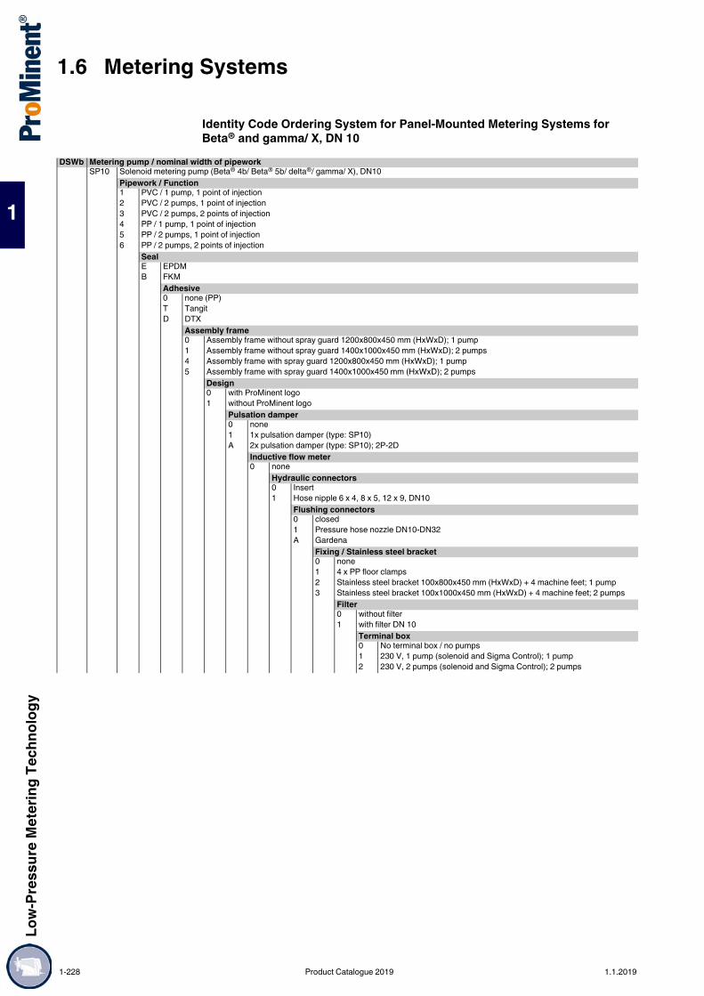
1.6 Metering SystemsLo
w-Pr
essu
re M
eter
ing Te
chno
logy
1
Identity Code Ordering System for Panel-Mounted Metering Systems for Beta® and gamma/ X, DN 10
DSWb Metering pump / nominal width of pipeworkSP10 Solenoid metering pump (Beta® 4b/ Beta® 5b/ delta®/ gamma/ X), DN10
Pipework / Function1 PVC / 1 pump, 1 point of injection2 PVC / 2 pumps, 1 point of injection3 PVC / 2 pumps, 2 points of injection4 PP / 1 pump, 1 point of injection5 PP / 2 pumps, 1 point of injection6 PP / 2 pumps, 2 points of injection
SealE EPDMB FKM
Adhesive0 none (PP)T TangitD DTX
Assembly frame0 Assembly frame without spray guard 1200x800x450 mm (HxWxD); 1 pump1 Assembly frame without spray guard 1400x1000x450 mm (HxWxD); 2 pumps4 Assembly frame with spray guard 1200x800x450 mm (HxWxD); 1 pump5 Assembly frame with spray guard 1400x1000x450 mm (HxWxD); 2 pumps
Design0 with ProMinent logo1 without ProMinent logo
Pulsation damper0 none1 1x pulsation damper (type: SP10)A 2x pulsation damper (type: SP10); 2P-2D
Inductive flow meter0 none
Hydraulic connectors0 Insert1 Hose nipple 6 x 4, 8 x 5, 12 x 9, DN10
Flushing connectors0 closed1 Pressure hose nozzle DN10-DN32A Gardena
Fixing / Stainless steel bracket0 none1 4 x PP floor clamps2 Stainless steel bracket 100x800x450 mm (HxWxD) + 4 machine feet; 1 pump3 Stainless steel bracket 100x1000x450 mm (HxWxD) + 4 machine feet; 2 pumps
Filter0 without filter1 with filter DN 10
Terminal box0 No terminal box / no pumps1 230 V, 1 pump (solenoid and Sigma Control); 1 pump2 230 V, 2 pumps (solenoid and Sigma Control); 2 pumps
1-228 Product Catalogue 2019 1.1.2019

Low-
Pres
sure
Met
ering
Tech
nolog
y
1.6 Metering Systems
1
* Please enter the Identity code for your chosen pump
Pump 100 without pump41 10 bar / 0.74 l/h, BT4b 1000PVT2000U1100000, 6x442 16 bar / 2.2 l/h, BT4b 1602PVT2000U1100000, 6x443 16 bar / 3.60 l/h, BT4b 1604PVT2000U1100000, 6x444 7 bar / 7.10 l/h, BT4b 0708PVT2000U1100000, 8x545 4 bar / 12.30 l/h, BT4b 0413PVT2000U1100000, 8x546 2 bar / 19.00 l/h, BT4b 0220PVT2000U1100000, 12x951 10 bar / 6.80 l/h, BT5b 1008PVT2000U1100000, 8x552 7 bar / 11.0 l/h, BT5b 0713PVT2000U1100000, 8x553 4 bar / 17.10 l/h, BT5b 0420PVT2000U1100000, 12x954 2 bar / 32.00 l/h, BT5b 0232NPE2000U1100000, 12x9D1 16 bar / 11.3 l/h, DLTa 1612PVT2000U11030DE0, 8x5D2 10 bar / 19.1 l/h, DLTa 1020PVT2000U11030DE0, 12x9D3 7 bar / 29.2 l/h, DLTa 0730PVT2000U11030DE0, 12x9D4 4 bar / 49.0 l/h, DLTa 0450PVT2000U11030DE0, DN10D5 2 bar / 75.0 l/h, DLTa 0280PVT2000U11030DE0, DN10X1 16 bar / 3.6 l/h, GMXa 1604PVT20000U110300DE, 6x4X2 7 bar / 7.6 l/h, GMXa 0708PVT20000U110300DE, 8x5X3 10 bar / 9.0 l/h, GMXa 1009PVT20000U110300DE, 8x5X4 4 bar / 13.5 l/h, GMXa 0414PVT20000U110300DE, 8x5X5 7 bar / 14.5 l/h, GMXa 0715PVT20000U110300DE, 8x5X6 2 bar / 19.7 l/h, GMXa 0220PVT20000U110300DE, 12x9X7 4 bar / 24.0 l/h, GMXa 0424PVT20000U110300DE, 12x9X8 2 bar / 45.0 l/h, GMXa 0245PVT00000U110300DE, 12x9
Pump 200 without pump41 10 bar / 0.74 l/h, BT4b 1000PVT2000U1100000, 6x442 16 bar / 2.2 l/h, BT4b 1602PVT2000U1100000, 6x443 16 bar / 3.60 l/h, BT4b 1604PVT2000U1100000, 6x444 7 bar / 7.10 l/h, BT4b 0708PVT2000U1100000, 8x545 4 bar / 12.30 l/h, BT4b 0413PVT2000U1100000, 8x546 2 bar / 19.00 l/h, BT4b 0220PVT2000U1100000, 12x951 10 bar / 6.80 l/h, BT5b 1008PVT2000U1100000, 8x552 7 bar / 11.0 l/h, BT5b 0713PVT2000U1100000, 8x553 4 bar / 17.10 l/h, BT5b 0420PVT2000U1100000, 12x954 2 bar / 32.00 l/h, BT5b 0232NPE2000U1100000, 12x9D1 16 bar / 11.3 l/h, DLTa 1612PVT2000U11030EN0, 8x5D2 10 bar / 19.1 l/h, DLTa 1020PVT2000U11030EN0, 12x9D3 7 bar / 29.2 l/h, DLTa 0730PVT2000U11030EN0, 12x9D4 4 bar / 49.0 l/h, DLTa 0450PVT2000U11030EN0, DN10D5 2 bar / 75.0 l/h, DLTa 0280PVT2000U11030EN0, DN10X1 16 bar / 3.6 l/h, GMXa 1604PVT20000U110300EN, 6x4X2 7 bar / 7.6 l/h, GMXa 0708PVT20000U110300EN, 8x5X3 10 bar / 9.0 l/h, GMXa 1009PVT20000U110300EN, 8x5X4 4 bar / 13.5 l/h, GMXa 0414PVT20000U110300EN, 8x5X5 7 bar / 14.5 l/h, GMXa 0715PVT20000U110300EN, 8x5X6 2 bar / 19.7 l/h, GMXa 0220PVT20000U110300EN, 12x9X7 4 bar / 24.0 l/h, GMXa 0424PVT20000U110300EN, 12x9X8 2 bar / 45.0 l/h, GMXa 0245PVT00000U110300EN, 12x9
Operating instructionsDE GermanEN EnglishES SpanishFR FrenchPT Portuguese
Certification01 CE certification
1.1.2019 Product Catalogue 2019 1-229

1.6 Metering SystemsLo
w-Pr
essu
re M
eter
ing Te
chno
logy
1
Identity Code Ordering System for Plate-Mounted Metering Systems for Sigma/ 1, DN 10
DSWb Metering pump / nominal width of pipeworkS110 Sigma/ 1, DN 10 (S1Cb/S1Ba 12017 - 07065: 20 - 65 l/h)
Pipework / Function1 PVC / 1 pump, 1 point of injection2 PVC / 2 pumps, 1 point of injection3 PVC / 2 pumps, 2 points of injection4 PP / 1 pump, 1 point of injection5 PP / 2 pumps, 1 point of injection6 PP / 2 pumps, 2 points of injection
SealE EPDMB FKM
Adhesive0 none (PP)T with extension for standby pump (same type as metering pump)D DTX
Assembly frame2 Assembly frame without spray guard 1600x1200x650 mm (HxWxD)6 Assembly frame with spray guard 1600x1200x650 mm (HxWxD)
Design0 with ProMinent logo1 without ProMinent logo
Pulsation damper0 none2 1x pulsation damper (type: S110)B 2x pulsation damper (type: S110); 2 pumps - 2 points of injection
Inductive flow meter0 none
Hydraulic connectors0 Insert2 Hose nozzles DN10
Flushing connectors0 closed1 Pressure hose nozzleA Gardena
Fixing / Stainless steel bracket0 none1 4 x PP floor clamps2 Stainless steel bracket 100x1200x650 mm (HxWxD) + machine feet
Filter0 without filter1 with filter
Terminal box0 No terminal box / no pumps1 230 V, 1 pump (solenoid/Sigma Control)2 230 V, 2 pumps (solenoid and Sigma Control)3 400 V, 1 pump (Sigma Basic)4 400 V, 2 pumps (Sigma Basic)
1-230 Product Catalogue 2019 1.1.2019

Low-
Pres
sure
Met
ering
Tech
nolog
y
1.6 Metering Systems
1
* Please enter the Identity code for your chosen pump
Pump 100 without pump11 12 bar / 17 l/h, S1BaH 12017PVTS000T000, 3/4-1012 10 bar / 22 l/h, S1BaH 10022PVTS000T000, 3/4-1013 12 bar / 35 l/h, S1BaH 12035PVTS000T000, 3/4-1015 10 bar / 44 l/h, S1BaH 10044PVTS000T000, 3/4-1016 10 bar / 50 l/h, S1BaH 10050PVTS000T000, 3/4-1017 7 bar / 65 l/h, S1BaH 07065PVTS000T000, 3/4-101A 12 bar / 21 l/h, S1CbH 12017PVTS000U1110S0EN, 3/4-101B 10 bar / 27 l/h, S1CbH 10022PVTS000U1110S0EN, 3/4-101C 12 bar / 42 l/h, S1CbH 12035PVTS000U1110S0EN, 3/4-101D 10 bar / 49 l/h, S1CbH 10050PVTS000U1110S0EN, 3/4-101F 10 bar / 53 l/h, S1CbH 10044PVTS000U1110S0EN, 3/4-101G 7 bar / 63 l/h, S1CbH 07065PVTS000U1110S0EN, 3/4-10
Pump 200 without pump11 12 bar / 17 l/h, S1BaH 12017PVTS000T000, 3/4-1012 10 bar / 22 l/h, S1BaH 10022PVTS000T000, 3/4-1013 12 bar / 35 l/h, S1BaH 12035PVTS000T000, 3/4-1015 10 bar / 44 l/h, S1BaH 10044PVTS000T000, 3/4-1016 10 bar / 50 l/h, S1BaH 10050PVTS000T000, 3/4-1017 7 bar / 65 l/h, S1BaH 07065PVTS000T000, 3/4-101A 12 bar / 21 l/h, S1CbH 12017PVTS000U1110S0EN, 3/4-101B 10 bar / 27 l/h, S1CbH 10022PVTS000U1110S0EN, 3/4-101C 12 bar / 42 l/h, S1CbH 12035PVTS000U1110S0EN, 3/4-101D 10 bar / 49 l/h, S1CbH 10050PVTS000U1110S0EN, 3/4-101F 10 bar / 53 l/h, S1CbH 10044PVTS000U1110S0EN, 3/4-101G 7 bar / 63 l/h, S1CbH 07065PVTS000U1110S0EN, 3/4-10
Operating instructionsDE GermanEN EnglishES SpanishFR FrenchPT Portuguese
Certification01 CE certification
1.1.2019 Product Catalogue 2019 1-231

1.6 Metering SystemsLo
w-Pr
essu
re M
eter
ing Te
chno
logy
1
Identity Code Ordering System for Plate-Mounted Metering Systems for Sigma/ 1, DN 15
* Please enter the Identity code for your chosen pump
DSWb Metering pump / nominal width of pipeworkS115 Sigma/ 1, DN 15 (S1Cb/S1Ba 07042 - 04120: 50 - 120 l/h)
Pipework / Function1 PVC / 1 pump, 1 point of injection2 PVC / 2 pumps, 1 point of injection3 PVC / 2 pumps, 2 points of injection4 PP / 1 pump, 1 point of injection5 PP / 2 pumps, 1 point of injection6 PP / 2 pumps, 2 points of injection
SealE EPDMB FKM
Adhesive0 none (PP)T with extension for standby pump (same type as metering pump)D DTX
Assembly frame2 Assembly frame without spray guard 1600x1200x650 mm (HxWxD)6 Assembly frame with spray guard 1600x1200x650 mm (HxWxD)
Design0 with ProMinent logo1 without ProMinent logo
Pulsation damper0 none3 1x pulsation damper (type: S115/S215)C 2x pulsation damper (type: S115/S215); 2 pumps - 2 points of injection
Inductive flow meter0 none
Hydraulic connectors0 Insert3 Hose nozzles DN15
Flushing connectors0 closed1 Pressure hose nozzle DN15A Gardena
Fixing / Stainless steel bracket0 none1 4 x PP floor clamps4 Stainless steel bracket 100x1200x650 mm (HxWxD) + 4 machine feet
Filter0 without filter1 with filter DN 15
Terminal box0 No terminal box / no pumps1 230 V, 1 pump (solenoid/Sigma Control)2 230 V, 2 pumps (solenoid and Sigma Control)3 400 V, 1 pump (Sigma Basic)4 400 V, 2 pumps (Sigma Basic)
Pump 100 without pump14 7 bar / 42 l/h, S1BaH 07042PVTS000T000, 1-1518 4 bar / 84 l/h, S1BaH 04084PVTS000T000, 1-1519 4 bar / 120 l/h, S1BaH 04120PVTS000T000, 1-151E 7 bar / 52 l/h, S1CbH 07042PVTS000U1110S0EN, 1-151H 4 bar / 101 l/h, S1CbH 04084PVTS000U1110S0EN, 1-151J 4 bar / 117 l/h, S1CbH 04120PVTS000U1110S0EN, 1-15
Pump 200 without pump14 7 bar / 42 l/h, S1BaH 07042PVTS000T000, 1-1518 4 bar / 84 l/h, S1BaH 04084PVTS000T000, 1-1519 4 bar / 120 l/h, S1BaH 04120PVTS000T000, 1-151E 7 bar / 52 l/h, S1CbH 07042PVTS000U1110S0EN, 1-151H 4 bar / 101 l/h, S1CbH 04084PVTS000U1110S0EN, 1-151J 4 bar / 117 l/h, S1CbH 04120PVTS000U1110S0EN, 1-15
Operating instructionsDE GermanEN EnglishES SpanishFR FrenchPT Portuguese
Certification01 CE certification
1-232 Product Catalogue 2019 1.1.2019

Low-
Pres
sure
Met
ering
Tech
nolog
y
1.6 Metering Systems
1
Identity Code Ordering System for Plate-Mounted Metering Systems for Sigma/ 2, DN 15
* Please enter the Identity code for your chosen pump
DSWb Metering pump / nominal width of pipeworkS215 Sigma 2 / DN15
Pipework / Function1 PVC / 1 pump, 1 point of injection2 PVC / 2 pumps, 1 point of injection3 PVC / 2 pumps, 2 points of injection4 PP / 1 pump, 1 point of injection5 PP / 2 pumps, 1 point of injection6 PP / 2 pumps, 2 points of injection
SealE EPDMB FKM
Adhesive0 none (PP)T with extension for standby pump (same type as metering pump)D DTX
Assembly frame2 Assembly frame without spray guard 1600x1200x650 mm (HxWxD)7 Assembly frame with spray guard 1600x1200x650 mm (HxWxD)
Design0 with ProMinent logo1 without ProMinent logo
Pulsation damper0 none3 1x pulsation damper (type: S115/S215)C 2x pulsation damper (type: S115/S215); 2 pumps - 2 points of injection
Inductive flow meter0 none
Hydraulic connectors0 Insert3 Hose nozzles DN15
Flushing connectors0 closed1 Pressure hose nozzle DN15A Gardena
Fixing / Stainless steel bracket0 none1 4 x PP floor clamps2 Stainless steel bracket 100x1200x650 mm (HxWxD) + 4 machine feet
Filter0 without filter1 with filter
Terminal box0 No terminal box / no pumps1 230 V, 1 pump (solenoid/Sigma Control)2 230 V, 2 pumps (solenoid and Sigma Control)3 400 V, 1 pump (Sigma Basic)4 400 V, 2 pumps (Sigma Basic)
Pump 100 without pump21 10 bar / 50 l/h, S2BaHM 16050PVTS000T000, 1-1522 10 bar / 88 l/h, S2BaHM 16090PVTS000T000, 1-1524 10 bar / 135 l/h, S2BaHM 16130PVTS000T000, 1-152A 10 bar / 61 l/h, S2CbH 16050PVTS000U1110S0EN, 1-152B 10 bar / 109 l/h, S2CbH 16090PVTS000U1110S0EN, 1-152C 10 bar / 131 l/h, S2CbH 16130PVTS000U1110S0EN, 1-15
Pump 200 without pump21 10 bar / 50 l/h, S2BaHM 16050PVTS000T000, 1-1522 10 bar / 88 l/h, S2BaHM 16090PVTS000T000, 1-1524 10 bar / 135 l/h, S2BaHM 16130PVTS000T000, 1-152A 10 bar / 61 l/h, S2CbH 16050PVTS000U1110S0EN, 1-152B 10 bar / 109 l/h, S2CbH 16090PVTS000U1110S0EN, 1-152C 10 bar / 131 l/h, S2CbH 16130PVTS000U1110S0EN, 1-15
Operating instructionsDE GermanEN EnglishES SpanishFR FrenchPT Portuguese
Certification01 CE certification
1.1.2019 Product Catalogue 2019 1-233

1.6 Metering SystemsLo
w-Pr
essu
re M
eter
ing Te
chno
logy
1
Identity Code Ordering System for Plate-Mounted Metering Systems for Sigma/ 2, DN 20
DSWb Metering pump / nominal width of pipeworkS220 Sigma 2 / DN20
Pipework / Function1 PVC / 1 pump, 1 point of injection2 PVC / 2 pumps, 1 point of injection3 PVC / 2 pumps, 2 points of injection4 PP / 1 pump, 1 point of injection5 PP / 2 pumps, 1 point of injection6 PP / 2 pumps, 2 points of injection
SealE EPDMB FKM
Adhesive0 noneT with extension for standby pump (same type as metering pump)D DTX
Assembly frame2 Assembly frame without spray guard 1600x1200x650 mm (HxWxD); 1 pump3 Assembly frame without spray guard 2000x1600x650 mm (HxWxD); 2 pumps7 Assembly frame without spray guard 1600x1200x650 mm (HxWxD); 1 pump8 Assembly of cabinet 2000x1600x650 mm (HxWxD); 2 pumps
Design0 with ProMinent logo1 without ProMinent logo
Pulsation damper0 none4 1x pulsation damper (type: S220)D 2x pulsation damper (type: S220); 2 pumps - 2 points of injection
Inductive flow meter0 none1 1x Inductive flow meter, Hast. C/PVDF, 4-20 mA, with display, min. flow=60 l/h2 2x inductive flow meters, Hast.C/PVDF, 4-20 mA, with display, 2 pumps - 2 points of injection,
min. flow = 60 l/hHydraulic connectors0 Insert4 Hose nozzles DN20
Flushing connectors0 closed1 Pressure hose nozzle DN20A Gardena
Fixing / Stainless steel bracket0 none1 4 x PP floor clamps4 Stainless steel bracket 100x1200x650 mm (HxWxD) + 4 machine feet; 1 pump5 Stainless steel bracket 100x1600x650 mm (HxWxD) + 4 machine feet; 2 pumps
Filter0 without filter3 with filter DN20
Terminal box0 No terminal box / no pumps1 230 V, 1 pump (solenoid/Sigma Control)2 230 V, 2 pumps (solenoid and Sigma Control)3 400 V, 1 pump (Sigma Basic)4 400 V, 2 pumps (Sigma Basic)
1-234 Product Catalogue 2019 1.1.2019

Low-
Pres
sure
Met
ering
Tech
nolog
y
1.6 Metering Systems
1
* Please enter the Identity code for your chosen pump
Pump 100 without pump23 7 bar / 126 l/h, S2BaHM 07120PVTS000T000, 1 1/2-2525 7 bar / 220 l/h, S2BaHM 07220PVTS000T000, 1 1/2-2526 4 bar / 350 l/h, S2BaHM 04350PVTS000T000, 1 1/2-252D 7 bar / 150 l/h, S2CbH 07120PVTS000U1110S0EN, 1 1/2-252E 7 bar / 271 l/h, S2CbH 07220PVTS000U1110S0EN, 1 1/2-252F 4 bar / 353 l/h, S2CbH 04350PVTS000U1110S0EN, 1 1/2-25
Pump 200 without pump23 7 bar / 126 l/h, S2BaHM 07120PVTS000T000, 1 1/2-2525 7 bar / 220 l/h, S2BaHM 07220PVTS000T000, 1 1/2-2526 4 bar / 350 l/h, S2BaHM 04350PVTS000T000, 1 1/2-252D 7 bar / 150 l/h, S2CbH 07120PVTS000U1110S0EN, 1 1/2-252E 7 bar / 271 l/h, S2CbH 07220PVTS000U1110S0EN, 1 1/2-252F 4 bar / 353 l/h, S2CbH 04350PVTS000U1110S0EN, 1 1/2-25
Operating instructionsDE GermanEN EnglishES SpanishFR FrenchPT Portuguese
Certification01 CE certification
1.1.2019 Product Catalogue 2019 1-235

1.6 Metering SystemsLo
w-Pr
essu
re M
eter
ing Te
chno
logy
1
Identity Code Ordering System for Plate-Mounted Metering Systems for Sigma/ 3, DN 25
DSWb Metering pump / nominal width of pipeworkS325 Sigma/ 3, DN 25 (S3Cb 120145 - 120330: 174 - 324 l/h)
Pipework / Function1 PVC / 1 pump, 1 point of injection2 PVC / 2 pumps, 1 point of injection3 PVC / 2 pumps, 2 points of injection4 PP / 1 pump, 1 point of injection5 PP / 2 pumps, 1 point of injection6 PP / 2 pumps, 2 points of injection
SealE EPDMB FKM
Adhesive0 noneT with extension for standby pump (same type as metering pump)D DTX
Assembly frame2 Assembly frame without spray guard 1600x1200x650 mm (HxWxD); 1 pump3 Assembly frame without spray guard 2000x1600x650 mm (HxWxD); 2 pumps7 Assembly frame without spray guard 1600x1200x650 mm (HxWxD); 1 pump8 Assembly of cabinet 2000x1600x650 mm (HxWxD); 2 pumps
Design0 with ProMinent logo1 without ProMinent logo
Pulsation damper0 none5 1x pulsation damper (type: S325)E 2x pulsation damper (type: S325); 2 pumps - 2 points of injection
Inductive flow meter0 none1 1x Inductive flow meter, Hast. C/PVDF, 4-20 mA, with display, min. flow=90 l/h2 2x inductive flow meters, Hast.C/PVDF, 4-20 mA, with display, 2 pumps - 2 points of injection,
min. flow = 90 l/hHydraulic connectors0 Insert5 Hose nozzles DN25
Flushing connectors0 closed4 Pressure hose nozzle DN25A Gardena
Fixing / Stainless steel bracket0 none1 4 x PP floor clamps4 Stainless steel bracket 100x1200x650 mm (HxWxD) + 4 machine feet; 1 pump5 Stainless steel bracket 100x1600x650 mm (HxWxD) + 4 machine feet; 2 pumps
Filter0 without filter4 with filter DN25
Terminal box0 No terminal box / no pumps1 230 V, 1 pump (solenoid/Sigma Control)2 230 V, 2 pumps (solenoid and Sigma Control)3 400 V, 1 pump (Sigma Basic)4 400 V, 2 pumps (Sigma Basic)
1-236 Product Catalogue 2019 1.1.2019

Low-
Pres
sure
Met
ering
Tech
nolog
y
1.6 Metering Systems
1
* Please enter the Identity code for your chosen pump
Pump 100 without pump31 10 bar / 146 l/h, S3BaH 120145PVTS000T000, 1 1/2-2531 10 bar / 208 l/h, S3BaH 120190PVTS000T000, 1 1/2-2533 10 bar / 292 l/h, S3BaH 120270PVTS000T000, 1 1/2-2534 10 bar / 365 l/h, S3BaH 120330PVTS000T000, 1 1/2-253A 10 bar / 182 l/h, S3CbH 120145PVTS000U1110S0EN, 1 1/2-253B 10 bar / 243 l/h, S3CbH 120190PVTS000U1110S0EN, 1 1/2-253C 10 bar / 365 l/h, S3CbH 120270PVTS000U1110S0EN, 1 1/2-25
Pump 200 without pump31 10 bar / 146 l/h, S3BaH 120145PVTS000T000, 1 1/2-2532 10 bar / 208 l/h, S3BaH 120190PVTS000T000, 1 1/2-2533 10 bar / 292 l/h, S3BaH 120270PVTS000T000, 1 1/2-2534 10 bar / 365 l/h, S3BaH 120330PVTS000T000, 1 1/2-253A 10 bar / 182 l/h, S3CbH 120145PVTS000U1110S0EN, 1 1/2-253B 10 bar / 243 l/h, S3CbH 120190PVTS000U1110S0EN, 1 1/2-253C 10 bar / 365 l/h, S3CbH 120270PVTS000U1110S0EN, 1 1/2-25
Operating instructionsDE GermanEN EnglishES SpanishFR FrenchPT Portuguese
Certification01 CE certification
1.1.2019 Product Catalogue 2019 1-237

1.6 Metering SystemsLo
w-Pr
essu
re M
eter
ing Te
chno
logy
1
IIdentity Code Ordering System for Plate-Mounted Metering Systems for Sigma/ 3, DN 32
DSWb Metering pump / nominal width of pipeworkS332 Sigma/ 3, DN 32 (S3Cb 070410 - 041030: 492 - 1000 l/h)
Pipework / Function1 PVC / 1 pump, 1 point of injection2 PVC / 2 pumps, 1 point of injection3 PVC / 2 pumps, 2 points of injection4 PP / 1 pump, 1 point of injection5 PP / 2 pumps, 1 point of injection6 PP / 2 pumps, 2 points of injection
SealE EPDMB FKM
Adhesive0 noneT with extension for standby pump (same type as metering pump)D DTX
Assembly frame2 Assembly frame without spray guard 1600x1200x650 mm (HxWxD); 1 pump3 Assembly frame without spray guard 2000x1600x650 mm (HxWxD); 2 pumps7 Assembly frame without spray guard 1600x1200x650 mm (HxWxD); 1 pump8 Assembly of cabinet 2000x1600x650 mm (HxWxD); 2 pumps
Design0 with ProMinent logo1 without ProMinent logo
Pulsation damper0 none6 1x pulsation damper (type: S332)F 2x pulsation damper (type: S332); 2 pumps - 2 points of injection
Inductive flow meter0 none1 1x Inductive flow meter, Hast. C/PVDF, 4-20 mA, with display, min. flow=150 l/h2 2x inductive flow meters, Hast.C/PVDF, 4-20 mA, with display, 2 pumps - 2 points of injection, min. flow
= 150 l/hHydraulic connectors0 Insert6 Hose nozzles DN32
Flushing connectors0 closed1 Pressure hose nozzle DN32A Gardena
Fixing / Stainless steel bracket0 none1 4 x PP floor clamps4 Stainless steel bracket 100x1200x650 mm (HxWxD) + 4 machine feet; 1 pump5 Stainless steel bracket 100x1600x650 mm (HxWxD) + 4 machine feet; 2 pumps
Filter0 without filter5 with filter DN32
Terminal box0 No terminal box / no pumps1 230 V, 1 pump (solenoid/Sigma Control)2 230 V, 2 pumps (solenoid and Sigma Control)3 400 V, 1 pump (Sigma Basic)4 400 V, 2 pumps (Sigma Basic)
1-238 Product Catalogue 2019 1.1.2019

Low-
Pres
sure
Met
ering
Tech
nolog
y
1.6 Metering Systems
1
* Please enter the Identity code for your chosen pump
Pump 100 without pump35 7 bar / 410 l/h, S3BaH 070410PVTS100T000, 2-3236 7 bar / 580 l/h, S3BaH 070580PVTS100T000, 2-3237 4 bar / 830 l/h, S3BaH 040830PVTS100T000, 2-3238 4 bar / 1030 l/h, S3BaH 041030PVTS100T000, 2-323D 7 bar / 500 l/h, S3CbH 070410PVTS100U1110S0EN, 2-323E 7 bar / 670 l/h, S3CbH 070580PVTS100U1110S0EN, 2-323F 4 bar / 1040 l/h, S3CbH 040830PVTS100U1110S0EN, 2-32
Pump 200 without pump35 7 bar / 410 l/h, S3BaH 070410PVTS100T000, 2-3236 7 bar / 580 l/h, S3BaH 070580PVTS100T000, 2-3237 4 bar / 830 l/h, S3BaH 040830PVTS100T000, 2-3238 4 bar / 1030 l/h, S3BaH 041030PVTS100T000, 2-323D 7 bar / 500 l/h, S3CbH 070410PVTS100U1110S0EN, 2-323E 7 bar / 670 l/h, S3CbH 070580PVTS100U1110S0EN, 2-323F 4 bar / 1040 l/h, S3CbH 040830PVTS100U1110S0EN, 2-32
Operating instructionsDE GermanEN EnglishES SpanishFR FrenchPT Portuguese
Certification01 CE certification
1.1.2019 Product Catalogue 2019 1-239

1.6 Metering SystemsLo
w-Pr
essu
re M
eter
ing Te
chno
logy
1
Modular and flexible for precise meteringCapacity: 40 – 1,000 l/h
The construction of the DULCODOS® modular enables them to be flexibly tailored to your processes. The system is configured via an identity code. The metering systems are delivered ready mounted and can be quickly and easily installed.
Your benefits Simple and fast installation, thanks to its ready-wired design Flexible, practical process integration with the identity code “DSKa” Minimal space requirement, thanks to compact construction Short delivery times due to the use of standard components Minimal stock of spare parts
Technical DetailsSelectable via the identity code: Metering system for the integration of a Sigma product range motor-driven metering pump Plastic or stainless steel brackets Splash guard PP, PVC or PVDF pipework EPDM or FPM seals VA base with machine feet Manometer for commissioning of the back pressure valves Hydraulic connectors, (d25 hose nozzles, welding/straight solvent unions, stainless steel sleeves) Electrical connectors Motor-driven metering pump SigmaIncluded in the standard scope of delivery: Leak sensor (contained in the standard scope of delivery) Flushing connectors with 3-way ball valve Pulsation damper with back pressure valve Relief valve with return line Hose nozzles on suction side and return in d 25
1.6.5 Metering System DULCODOS® modular (DSKa)
The ready-wired modular metering system DULCODOS® is used for the ultra-precise metering of chemicals. It has a modular design and can be flexibly integrated into the most varied applications.
P_DD_053_SW1
1-240 Product Catalogue 2019 1.1.2019

Low-
Pres
sure
Met
ering
Tech
nolog
y
1.6 Metering Systems
1
Identity Code Ordering System, DULCODOS® modular (DSKa)DSKa DULCODOS modular DSKa
S DULCODOS modular for the installation of a Sigma motor-driven metering pumpAssembly frame0 PP assembly frame1 Stainless steel assembly frame
Splash guard0 without splash guard1 with splash guard
Design0 with ProMinent logo1 without ProMinent logo
Stainless steel base frame0 none1 with stainless steel base including 4 machine feet
PipeworkPCED PVC / EPDM - with accumulatorPCBD PVC / FKM - with accumulatorPPED PP / EPDM - with accumulatorPVBD PVDF / FKM - with accumulatorPCEH PVC / EPDM - with pulsation damper (Hidracar)PCBH PVC / FKM - with pulsation damper (Hidracar)PPEH PP / EPDM - with pulsation damper (Hidracar)PVBH PVDF / FKM - with pulsation damper (Hidracar)
Options0 Floor installation (2 x brackets)1 Test and filling device for diaphragm damper + gas filling adapter G14"-VGB
Manometer with diaphragm seal (for commissioning)0 Floor installation (2 x brackets)1 PVC2 PP3 PVDF
Hydraulic connectors discharge side0 none (ball valve with straight union)– Hose nozzle1 Nozzle d25 PVC, for hose 25x342 Nozzle d25 PP, for hose 25x343 Nozzle d25 PVDF, for hose 25x34 (1041960)– Straight solvent union/welding sleeve (for follow-on pipework)4 Straight solvent union d25, PVC-U (1030214)5 Straight solvent union d25, PVC-C (1040280)6 Welding sleeve d25 PP-H (1035825)7 Welding sleeve d25 PVDF (1027466)– Insert for stainless steel pipework (DIN 11850)A Insert for stainless steel pipe 19x1.5 (1040734)B Insert for stainless steel pipe 23x1.5 (1039507)C Insert for stainless steel pipe 29x1.5(1039549)
Electrical connectionK Terminal boxH Master switchR Repair switch
1.1.2019 Product Catalogue 2019 1-241

1.6 Metering SystemsLo
w-Pr
essu
re M
eter
ing Te
chno
logy
1
Pump00 no pump, no adapter01 no pump, with adapter set Sigma 1 to 65 l/h02 no pump, with adapter set Sigma 1 to 120 l/h03 no pump, with adapter set Sigma 2, Basic to 135 l/h04 no pump, with adapter set Sigma 2, Basic to 350 l/h05 no pump, with adapter set Sigma 2, Control to 131 l/h06 no pump, with adapter set Sigma 2, Control to 353 l/h07 no pump, with adapter set Sigma 3, to 365 l/h08 no pump, with adapter set Sigma 3, to 670 l/h09 no pump, with adapter set Sigma 3, to 1040 l/h– Sigma 111 12 bar / 17 l/h, S1BaH 12017PVTS000T000, 3/4-1012 10 bar / 22 l/h, S1BaH 10022PVTS000T000, 3/4-1013 12 bar / 35 l/h, S1BaH 12035PVTS000T000, 3/4-1014 10 bar / 44 l/h, S1BaH 10044PVTS000T000, 3/4-1015 10 bar / 50 l/h, S1BaH 10050PVTS000T000, 3/4-1016 7 bar / 65 l/h, S1BaH 07065PVTS000T000, 3/4-1017 7 bar / 42 l/h, S1BaH 07042PVTS000T000, 1-1518 4 bar / 84 l/h, S1BaH 04084PVTS000T000, 1-1519 4 bar / 120 l/h, S1BaH 04120PVTS000T000, 1-15– Sigma 1 - Control1A 12 bar / 21 l/h, S1CbH 12017PVTS000U1110S0DE, 3/4-101B 10 bar / 27 l/h, S1CbH 10022PVTS000U1110S0DE, 3/4-101C 12 bar / 42 l/h, S1CbH 12035PVTS000U1110S0DE, 3/4-101D 10 bar / 49 l/h, S1CbH 10050PVTS000U1110S0DE, 3/4-101E 10 bar / 53 l/h, S1CbH 10044PVTS000U1110S0DE, 3/4-101F 7 bar / 63 l/h, S1CbH 07065PVTS000U1110S0DE, 3/4-101G 7 bar / 52 l/h, S1CbH 07042PVTS000U1110S0DE, 1-151H 4 bar / 101 l/h, S1CbH 04084PVTS000U1110S0DE, 1-151J 4 bar / 117 l/h, S1CbH 04120PVTS000U1110S0DE, 1-15– Sigma 2 - Basic21 10 bar / 50 l/h, S2BaHM 16050PVTS000T000, 1-1522 10 bar / 88 l/h, S2BaHM 16090PVTS000T000, 1-1523 10 bar / 135 l/h, S2BaHM 16130PVTS000T000, 1-1524 7 bar / 126 l/h, S2BaHM 07120PVTS000T000, 1 1/2-2525 7 bar / 220 l/h, S2BaHM 07220PVTS000T000, 1 1/2-2526 4 bar / 350 l/h, S2BaHM 04350PVTS000T000, 1 1/2-25– Sigma 2 - Control2A 10 bar / 61 l/h, S2CbH 16050PVTS000U1110S0DE, 1-152B 10 bar / 109 l/h, S2CbH 16090PVTS000U1110S0DE, 1-152C 10 bar / 131 l/h, S2CbH 16130PVTS000U1110S0DE, 1-152D 7 bar / 150 l/h, S2CbH 07120PVTS000U1110S0DE, 1 1/2-252E 7 bar / 271 l/h, S2CbH 07220PVTS000U1110S0DE, 1 1/2-252F 4 bar / 353 l/h, S2CbH 04350PVTS000U1110S0DE, 1 1/2-25– Sigma 3 - Basic31 10 bar / 146 l/h, S3BaH 120145PVTS000T000, 1 1/2-2532 10 bar / 208 l/h, S3BaH 120190PVTS000T000, 1 1/2-2533 10 bar / 292 l/h, S3BaH 120270PVTS000T000, 1 1/2-2534 10 bar / 365 l/h, S3BaH 120330PVTS000T000, 1 1/2-2535 7 bar / 410 l/h, S3BaH 070410PVTS100T000, 2-3236 7 bar / 580 l/h, S3BaH 070580PVTS100T000, 2-3237 4 bar / 830 l/h, S3BaH 040830PVTS100T000, 2-3238 4 bar / 130 l/h, S3BaH 041030PVTS100T000, 2-32– Sigma 3 - Control3A 10 bar / 182 l/h, S3CbH 120145PVTS000U1110S0DE, 1 1/2-253B 10 bar / 243 l/h, S3CbH 120190PVTS000U1110S0DE, 1 1/2-253C 10 bar / 365 l/h, S3CbH 120270PVTS000U1110S0DE, 1 1/2-253D 7 bar / 500 l/h, S3CbH 070410PVTS100U1110S0DE, 2-323E 7 bar / 670 l/h, S3CbH 070580PVTS100U1110S0DE, 2-323F 4 bar / 140 l/h, S3CbH 040830PVTS100U1110S0DE, 2-32
Operating instructionsDE GermanEN EnglishES SpanishFR FrenchPT Portuguese
Certification01 CE certification
1-242 Product Catalogue 2019 1.1.2019

Low-
Pres
sure
Met
ering
Tech
nolog
y
1.6 Metering Systems
1
Corrosion is the last thing you need with the majority of applications. That is why Hydrazin protects. Chemical tank ranging from 140 to 250 litres
Hydrazine acts as an oxygen binding agent, is volatile in steam and prevents corrosion. As it is carcinogenic, the dispensing and metering systems need to be gas-tight so that no hydrazine vapours can escape. Our systems comply with these requirements.
Your benefits Gas-tight design Precise metering Protects the environment
Field of application Steam circuits Power plantsHydrazine is used as an oxygen binding agent in the process water sector, predominantly with steam generation. It is a carcinogenic agent and special care is therefore needed when handling it.It therefore has to be ensured that the activation threshold for hydrazine is not exceeded with correct and proper use of closed and gas-tight systems.
DesignReady-to-use assembled metering system essentially consisting of: Gas-tight chemical tank made of PE with a litre scale, with lockable screw lid and manual stirrer Each with a dispensing and metering pump with suction assembly, level switch, as well as complete
rigid PVC pipework with two ball valves, the measuring tank and activated charcoal filter
Accessories5 m metering line 8/12 mm Ø and stainless steel metering valve 8 mm Ø/1/2"Electrical connection 230 V ±10%, 50…60 Hz
Hydrazine Dispensing and Metering System, Completely Ready Mounted
Accessories
1.6.6 Metering System DULCODOS® Hydrazin
DULCODOS® Hydrazin batching and metering systems are used for manual batching and automatic metering of diluted hydrazine solutions. And, of course, they also comply with all environmental and safety requirements.
pk_7_0781 Activated charcoal filter2 Bleed/vent line3 Apportioning unit4 Metering tank5 Hydrazin 15 returnable canister6 Quick release coupling7 Metering line8 Gas shuttle line9 Refilling pump10 Metering pump11 Fill water
The metering system is supplied with a hose connection, which fits on a conventional drain system. This drain system is produced by MicroMatic, Gräfelfing/Munich.
Metering Tank Contents
Metering pumpCapacity
Metering pumpFeed Rate
Transfer PumpDischarge Flow
Order no.
130 l 7.1 l/h 7.0 bar 17 l/h 913018250 l 11.0 l/h 7.0 bar 32 l/h 913019
Order no.Sampling set, stainless steel 1003964
1.1.2019 Product Catalogue 2019 1-243
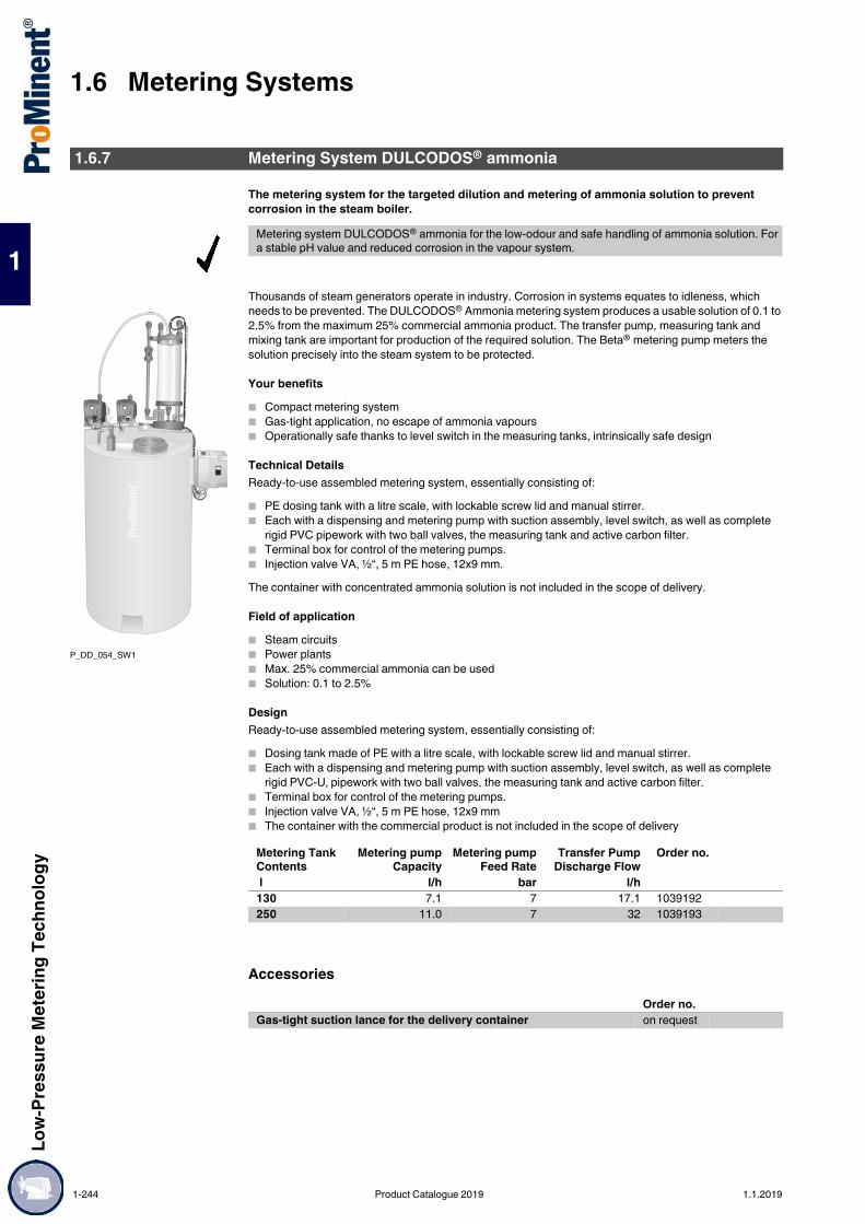
1.6 Metering SystemsLo
w-Pr
essu
re M
eter
ing Te
chno
logy
1
The metering system for the targeted dilution and metering of ammonia solution to prevent corrosion in the steam boiler.
Thousands of steam generators operate in industry. Corrosion in systems equates to idleness, which needs to be prevented. The DULCODOS® Ammonia metering system produces a usable solution of 0.1 to 2.5% from the maximum 25% commercial ammonia product. The transfer pump, measuring tank and mixing tank are important for production of the required solution. The Beta® metering pump meters the solution precisely into the steam system to be protected.
Your benefits Compact metering system Gas-tight application, no escape of ammonia vapours Operationally safe thanks to level switch in the measuring tanks, intrinsically safe design
Technical DetailsReady-to-use assembled metering system, essentially consisting of: PE dosing tank with a litre scale, with lockable screw lid and manual stirrer. Each with a dispensing and metering pump with suction assembly, level switch, as well as complete
rigid PVC pipework with two ball valves, the measuring tank and active carbon filter. Terminal box for control of the metering pumps. Injection valve VA, ½“, 5 m PE hose, 12x9 mm.The container with concentrated ammonia solution is not included in the scope of delivery.
Field of application Steam circuits Power plants Max. 25% commercial ammonia can be used Solution: 0.1 to 2.5%
DesignReady-to-use assembled metering system, essentially consisting of: Dosing tank made of PE with a litre scale, with lockable screw lid and manual stirrer. Each with a dispensing and metering pump with suction assembly, level switch, as well as complete
rigid PVC-U‚ pipework with two ball valves, the measuring tank and active carbon filter. Terminal box for control of the metering pumps. Injection valve VA, ½“, 5 m PE hose, 12x9 mm The container with the commercial product is not included in the scope of delivery
Accessories
1.6.7 Metering System DULCODOS® ammonia
Metering system DULCODOS® ammonia for the low-odour and safe handling of ammonia solution. For a stable pH value and reduced corrosion in the vapour system.
P_DD_054_SW1
Metering Tank Contents
Metering pumpCapacity
Metering pumpFeed Rate
Transfer PumpDischarge Flow
Order no.
l l/h bar l/h130 7.1 7 17.1 1039192250 11.0 7 32 1039193
Order no.Gas-tight suction lance for the delivery container on request
1-244 Product Catalogue 2019 1.1.2019

Low-
Pres
sure
Met
ering
Tech
nolog
y
1.6 Metering Systems
1
Fast and precise disinfection of potable water
Water supply companies ensure high quality of potable water in accordance with the applicable Drinking Water Ordinance (TrinkwV 2001). In spite of this, emergency situations can nevertheless arise that require rapid disinfection.ProMinent supplies a compact metering station, which is immediately ready for use and performs emergency disinfection, for instance after flooding or pipe ruptures, in compliance with the regulations.All disinfectants permitted in accordance with the Drinking Water Ordinance 2001 and the List of Permitted Substances (§ 11) can be used. Emergency potable water disinfection can also be used when commissioning new pipes, after repairs or after long downtimes.
Your benefits Connection-ready handy metering system (0.02 – 1.55 l/h, 10 bar) Integrated metering and pressure monitoring Low-pulsation metering by guided discharge strokes Volume-proportional metering if customer has a flow water meter fitted adequate for treatment of up to 372 m3/h when adding 0.5 mg/l to 155 m3/h of chlorine with the addition
of 1.2 mg/l (when using sodium-calcium hypochlorite 12%)
Technical DetailsReady-to-use assembled metering system, essentially consisting of: Assembly frame for installation of a container for disinfectant (e.g. sodium-calcium hypochlorite, 12 %).
500x500x1000 mm (LxWxH). Metering pump gamma/ X, GMXa 1604, 1.55 l/h, 10 bar. Injection lance, ½“, 10 m PVC hose, 6x12 mm
Field of application Emergency disinfection of potable water Disinfection after downtimes Disinfection during commissioning
1.6.8 Metering System DULCODOS® Emergency Potable Water Disinfection
Handy metering system for emergency potable water disinfection. For fast use against micro-organisms.
P_DD_0051_SW1
Metering pumpCapacity
Order no.
l/hPotable water disinfection with GMXa 1604 1.6 1081318
1.1.2019 Product Catalogue 2019 1-245

1.6 Metering SystemsLo
w-Pr
essu
re M
eter
ing Te
chno
logy
1
Proportional Metering of Phosphate
The liquid phosphate is added to the potable water proportional to the volume. The flow meter sends pulses to the gamma/ L pump. The metering volume is adjusted by increasing or decreasing the incoming pulses.
pk_7_093
Tasks and requirementsMetering of phosphate to potable water to prevent lime deposits and corrosion in the piping
Operating conditions Treatment of potable water Fluctuating water demand Water temperature between 4 – 30 °C
Application information Proportional metering of phosphate depending on the water supply Control of the metering pump by a contact water meter Measurement of the metering pump capacity during commissioning
Solution DULCODOS® eco with 140-litre metering tank and drip pan gamma/ L with contact input and pulse control Contact water meter
Benefits Constant solution concentration even minimal fluctuating water supply Fully-automatic operation with minimal staff and maintenance Flexible process design thanks to adaptation of the pump to various concentration demands
1.6.9 Application Examples
Product: DULCODOS® ecoFeed chemical: PhosphateIndustry: Potable waterApplication: Potable water conditioning
1-246 Product Catalogue 2019 1.1.2019

Low-
Pres
sure
Met
ering
Tech
nolog
y
1.6 Metering Systems
1
Inhibitor Metering in Cooling Water
The corrosion inhibitor is metered proportionally to the fresh water. The water meter detects the volume of feed water and transmits the pulses to the gamma/ L pump.
pk_7_060_1
Tasks and requirementsMetering of corrosion inhibitors to supply water to prevent lime deposits and corrosion in the cooling water circuit.
Operating conditions Treatment of flow water Fluctuating water demand Water temperature between 4 – 20 °C
Application information Proportional metering of inhibitor depending on the water supply Control of the metering pump by a contact water meter Calibration of the metering pump capacity during commissioning
Solution DULCODOS® panel including standby pump gamma/ L with contact input and pulse control Contact water meter
Benefits Protection against corrosion in the pipework and heat exchanger Constant solution concentration even with fluctuating water supply Fully-automatic operation with minimal staff and maintenance Flexible process design thanks to adaptation of the pump to various concentration demands
Product: DULCODOS® panel / DULCODOS® universalFeed chemical: Corrosion inhibitorIndustry: Process industry, Power plantsApplication: cooling water treatment
1.1.2019 Product Catalogue 2019 1-247

1.7 Domestic Water SystemsLo
w-Pr
essu
re M
eter
ing Te
chno
logy
1
1.7Domestic Water Systems
Proportional Flow Dosing System for Liquid DosingPromatik®
Metering systems protect pipework, fittings, and appliances, such as boilers, washing machines and dishwashers, from corrosion and limescale. Active substances, like silicate, phosphate or silicate phosphate mixtures, can be metered here. These active substances form a protective layer in the pipework and reduce aggressiveness and sedimentation in the water.
SilicateAs a corrosion inhibitor to prevent rust formation: "brownish water" in galvanised pipework, "pitting": needle-like holes in the pipework. Applications include soft, corrosive types of water with a high percentage of aggressive carbonic acid. The silicate is used to raise the pH value closer to a lime-carbonic acid equilibrium. Hydrolysis produces a silica gel that forms a thin protective layer in the pipework and fittings and thus prevents corrosion.
PhosphateAs ortho and polyphosphate to prevent limescale and corrosion in hard water up to max. 20 CH (carbonate hardness). Hard water salts, such as calcium and magnesium ions, responsible for limescale are thereby stabilised, i.e. these ions remain dissolved in the water and do not form limescale on the pipe walls. Growth on the pipes is thus prevented and there are no deposits of limescale on heating coils, dramatically reducing their efficiency. A thin, solid protective layer is formed. Mixtures containing silicate and phosphate act as corrosion and limescale inhibitors for soft and medium-hard water. Continuous top-up of the feed chemical is required to maintain this protective layer, otherwise it will degrade within a few days.
EXACTAPHOS®
EXACTAPHOS® metering solutions are matched to the capacity of the Promatik® and DULCODOS® units. This ensures that the percentages of max 40 mg/l SiO2 of silicate and/or 6.7 mg/l of phosphate PO4 (5 mg/l P2O5) are adhered to, as laid down by the "Drinking Water Ordinance".
Function of the systemsIn a flow of water, the contact water meter transmits pulses with a fixed pulse interval corresponding to the flow to the metering pump. Each of these pulses results in a metering stroke of the metering pump, thereby feeding the metering solution. The metering volume per stroke can thus be adjusted continuously between 100 and 50 % using the stroke adjustment dial. Because of the very low starting limit and the short pulse interval, a constant volume-proportional addition of chemicals can always be maintained, from minimum water flow rate to maximum load, guaranteeing the best process result.
Promatik® proportional flow dosing systemConsisting of a Beta® metering pump with sound insulation plate, contact water meter, suction assembly with foot valve and 2-phase level switch with pre-warning, acting as a low flow contact and empty signal, injection valve and metering line. With wall brackets to mount the metering pump. Fitting position of the contact water meter – horizontal and vertical. DVGW-tested in conjunction with the EXACTAPHOS® metering solution. DVGW No. NW-9101 CM 0179.
1.7.1 Systems for Domestic Water Installations
P_PNM_0032_SW1
1-248 Product Catalogue 2019 1.1.2019

Low-
Pres
sure
Met
ering
Tech
nolog
y
1.7 Domestic Water Systems
1
Metering System Promatik®
Protects pipework, fittings, and appliances from corrosion and limescale.For flows of 4 – 25 m3/h
In a flow of water, the contact water meter transmits pulses with a fixed pulse interval corresponding to the pulses to the metering pump in line with the flow. Each of these pulses results in a metering stroke of the metering pump, thereby feeding the metering solution. The metering volume per stroke can thus be adjusted continuously between 100 and 50% using the stroke adjustment dial. Because of the very low starting limit and short pulse interval, a constant volume-proportional addition of chemicals can always be maintained from minimum water flow rate to maximum load, thereby guaranteeing the best process result
Your benefits DVGW-tested in conjunction with the EXACTAPHOS® metering solution. DVGW No. NW-9101 CM
0179. The EXACTAPHOS® metering solutions are matched to the capacity of the Promatik® metering
systems. Fitting position of the water meter – horizontal and vertical.
Field of applicationPotable water treatment
The proportional metering system Promatik® is used in the potable water sector for the flow-dependent, adjustable metering of liquid media, like the EXACTAPHOS®. It consists of the metering pump Beta®, a contact water meter, a suction assembly with foot valve, level switch and wall bracket, and an injection valve and metering line.
P_PNM_0032_SW1
Promatik® type S 4 S 10 S 16 S 25Maximum flow Q max. m3/h 4 10 16 25Lower operating limit (horizontal) m3/h 0,025 0,063 0,1 0,16Metering interval approx. l/stroke 0.7 1.1 1.8 2.8Feed rate 50-100 % ml/m3 50 – 165 50 – 165 50 – 165 50 – 165Operating pressure bar 1 – 10 1 – 10 1 – 10 1 – 10Metering pump type BT4b 1000 BT4b 1601 BT4b 1602 BT4b 1604Meter connecting thread G 1 B G 1 1/4 B G 2 B G 2 1/2 BScrew connector width R 3/4 R 1 R 1 1/2 R 2Length without thread mm 190 260 300 270
1.1.2019 Product Catalogue 2019 1-249

1.7 Domestic Water SystemsLo
w-Pr
essu
re M
eter
ing Te
chno
logy
1
Metering System Promatik®
Materials Dosing head/valves: Polypropylene (PP) Metering diaphragm EPDM with PTFE insert Seals: EPDM Valve balls: ceramic Float switches: PP Suction assembly: flexible PVC Discharge tube: PE
EXACTAPHOS® SP 210Silicate phosphate liquid metering solution. Drinking water treatment for soft water. Promatik® compact metering system.
EXACTAPHOS® P 612Phosphate liquid metering solution. Drinking water treatment for medium hard water. Promatik® compact metering system.
EXACTAPHOS® P 1020Phosphate liquid metering solution. Drinking water treatment for hard water. Promatik® compact metering system.
P_PNM_0032_SW1
Shipping weight approx. Order no. kg
S 4 split system 6 1078282S 10 split system 7 1078283S 16 split system 9 1078284S 25 split system 11 1078285
1.7.2 Chemicals
Volume Order no. l
EXACTAPHOS® SP 210 20 950097EXACTAPHOS® SP 210 200 950043
Volume Order no. l
EXACTAPHOS® P 612 20 950098EXACTAPHOS® P 612 200 950048
Volume Order no. l
EXACTAPHOS® P 1020 20 950099EXACTAPHOS® P 1020 200 950053
1-250 Product Catalogue 2019 1.1.2019

Proc
ess m
eter
ing te
chno
logy
2.1 Overview of Process Metering Pumps
2
2.0.1Product Catalogue 2019.
PK_0_001_4_2018
Overview of Process Metering Pumps
2.1.1 Selection Guide
gamma Xgamma XL
Hydro 2 / 3 / 4
Makro/ 5M5Ha
MfS / MhS / PS
MHHP
Evolution 1 / 2 / 3 / 4
Type EXBb TZMb M5Ma HP2a HP3a HP4a M5Ha SBKa/SCKa
MTKa TZKa M5Ka
Stroke length mm 1.25 0 - 10 0 - 20 15 15 20 0 - 50 0 - 15 0 - 15 0 - 20 0 - 50Connecting rod force N 2,000 8,000 10,000 2,000 4,200 5,800 10,000 1,700 2,500 8,000 10,000
Type EF1a EF2a EF3a EF4a EP1a EP2a EF1F EF2F EF3F EF4FStroke length mm 0 - 15 0 - 15 0 - 25 0 - 40 0 - 15 0 - 15 15 15 25 40Connecting rod force N 2,300 5,400 8,000 15,700 2,300 5,400 2,300 5,400 8,000 15,700
Type S 18 S 35 S 80 S 180 S 600 S 1400 Rb 15 Rb 150 ZentriplexStroke length mm 0 - 15 0 - 20 0 - 20 0 - 40 0 - 40 0 - 60 0 - 15 0 - 32 40Connecting rod force N 1,750 3,500 14,000 18,000 40,000 60,000 1,800 15,000 18,000
1.1.2019 Product Catalogue 2019 2-1

2.1 Overview of Process Metering PumpsPr
oces
s met
ering
tech
nolog
y
2
pk_3_07
2.1.2 Installation Applications
2-2 Product Catalogue 2019 1.1.2019

Proc
ess m
eter
ing te
chno
logy
2.2 Diaphragm Process Metering Pumps
2
2.2Diaphragm Process Metering Pumps
Precise metering with explosion protection Capacity range of single head pump: 0.19 – 60 l/h; 10 – 1.5 bar
The ATEX-compliant diaphragm metering pump EXtronic® (EXBb) is tested and approved in line with EN 60079/-1 for the ignition type "compression-resistant enclosures" and thus offers the maximum level of protection. The short-stroke solenoid and the complete pump control are integrated in the pump housing so that, together with the explosion-proof power end, there is IP 65 protection against contact and moisture as per EN 60529 even when the front cover is open.
Your benefitsOptimum adaptation for use in areas at risk from explosion ATEX-compliant in line with EExd IIC T6 and EExd I/IIC T6 Excellent operating and functional reliability by a microprocessor controller, which compensates for
fluctuations of mains voltage and automatically switches from 50 to 60 Hz operation Broad range of applications with an operating voltage of 500 V, 230 V and 115 V Ease of integration into processes thanks to the range of control types (internal, external contact,
analogue) Also suitable for gaseous media, thanks to self-bleeding head
Technical Details Stroke length: 1.25 mm, Rod force: 2,000 N Stroke length adjustment range: 0 – 100% in operation and idle Stroke length adjustment: manually by scaled rotary dial Metering reproducibility is better than ± 2% within the 30 – 100% stroke length range under defined
conditions and with correct installation. Observe the information in the operating instructions DEVELOPAN® metering diaphragm with PTFE coating with diaphragm rupture control Wetted materials: Polypropylene, PVC, PTFE with carbon, clear acrylic, stainless steel, special designs
available on request Degree of protection: IP 65 (also with open front cover) Short stroke solenoid drive and complete pump control integrated in the pump housing "Internal", "External contact" and "Analogue" control inputs are available, the latter two also available as
intrinsically safe and approved to EN 60079-11
EXBb G for use in areas at risk from gases and vapours, degree of protection EEx [i,a] d IIC T6
This means: EEx - Equipment complies with European standards [i,a] - Control input is intrinsically safe when 2 independent errors occur d - Type of ignition protection, compression-resistant enclosure IIC - Explosion group II for all areas at risk from explosion with the exception of mining, sub-group IIC
(includes IIA and IIB) T6 - Temperature class permissible for gases and vapours with ignition temperature > 85 °C
EXBb M for use in mines at risk from firedamp, degree of protection EEx [i,a] d I/IIC T6
This means: EEx - Equipment complies with European standards [i,a] - Control input is intrinsically safe when 2 independent errors occur d - Type of ignition protection, compression-resistant enclosure IC - Explosion group I for mines at risk from firedamp IIC - Explosion group II for all areas at risk from explosion with the exception of mining, sub-group IIC
(includes IIA and IIB) T6 - Temperature class permissible for gases and vapours with ignition temperature > 85 °C
Field of application Oil, gas and petrochemicals Mining For use in areas at risk of gases and vapours Use in mines at risk from firedamp
2.2.1 Diaphragm Metering Pump ProMinent EXtronic®
The diaphragm metering pump EXtronic® is perfectly suited for the sensitive use of liquid media in facilities with an explosive gas atmosphere as well as for mines at risk of firedamp, as it is approved in compliance with the EU EX Regulation 2014/34/EU (ATEX).
pk_1_020Control type "Internal" Stroke length adjustment 1:10, stroke rate adjustment 1:25, total adjustment range 1:250.
pk_1_019Control type "External Contact" Stroke length adjustment 1:10, Stroke frequency control 0 - 100% dependant upon external switch contacts. *)
pk_1_018Control type "Analogue" Stroke length adjustment 1:10, Stroke frequency control 0-100 % proportional to analogue signal 0/4-20 mA. *)*) The electrical cables for mains connection, contact or analogue control are already connected to the pump. Observe all instructions concerning connecting and activating electrical systems.
1.1.2019 Product Catalogue 2019 2-3

2.2 Diaphragm Process Metering PumpsPr
oces
s met
ering
tech
nolog
y
2
Technical Data
Materials in Contact With the Medium
Type EXBb Delivery rate atmax. back pressure
Delivery rate atmedium back pressure
Strokerate
oØ x iØ Suction lift Shipping weightPP,NP,TT-SS
bar l/h ml/stroke
bar l/h ml/stroke
Strokes/min
mm m WC kg
EXBb1000 10 0.19 0.03 5 0.27 0.04 120 6 x 4 1.5 122501 25 1.14 0.15 20 1.10 0.17 120 6 x 4 5.0 –1601 16 1.00 0.15 8 1.30 0.18 120 6 x 4 5.0 121201 12 1.70 0.23 6 2.00 0.28 120 6 x 4 5.0 120803 8 3.70 0.51 4 3.90 0.54 120 6 x 4 3.0 121002 10 2.30 0.31 5 2.70 0.38 120 8 x 5 5.0 120308 3 8.60 1.20 1 10.30 1.43 120 8 x 5 5.0 122502 25 2.00 0.28 20 2.20 0.31 120 8 x 5 5.0 131006 10 6.00 0.83 5 7.20 1.00 120 8 x 5 5.0 130613 6 13.10 1.82 3 14.90 2.07 120 8 x 5 5.5 130417 3 17.40 2.42 2 17.90 2.49 120 12 x 9 4.5 132505 25 4.20 0.64 20 4.80 0.73 110 8 x 5 5.0 161310 13 10.50 1.59 6 11.90 1.80 110 8 x 5 5.0 160814 8 14.00 2.12 4 15.40 2.33 110 12 x 9 5.0 160430 3 27.00 4.09 2 29.50 4.47 110 DN 10 5.0 160260 1 60.00 9.09 – – – 110 DN 15 1.5 16
EXtronic® metering pumps for high viscosity media1002 10 2.30 0.31 5 2.70 0.38 120 DN 10 1.8 –1006 10 6.00 0.83 5 7.20 1.00 120 DN 10 2.0 –1310 10 10.50 1.59 5 11.90 1.80 110 DN 15 2.8 –0814 8 14.00 2.12 4 15.40 2.33 110 DN 15 2.0 –
EXtronic® metering pumps with self-bleeding liquid end1601 16 0.66 0.09 – – – 120 6 x 4 1.8 –1201 12 1.00 0.14 – – – 120 6 x 4 2.0 –0803 8 2.40 0.33 – – – 120 6 x 4 2.8 –1002 10 1.80 0.25 – – – 120 6 x 4 2.0 –
* Shipping weight for EXBb M version… additional 14 kg** The data given here represent guaranteed minimum values, achieved with medium water at room temperature.
Liquid end Suction/discharge connector
Seals Balls (connection 6-12 mm)
Balls (connection DN 10 and DN 15)
PP1 Polypropylene Polypropylene EPDM Ceramic Borosilicate glassPP4* Polypropylene Polypropylene EPDM - CeramicNP1 Plexiglass PVC FKM A Ceramic Borosilicate glassNP3 Plexiglass PVC FKM B Ceramic -NS3** Plexiglass PVC FKM B Ceramic -PS3** PVC PVC FKM B Ceramic -TT1 PTFE with carbon PTFE with carbon PTFE Ceramic CeramicSS .. Stainless steel mat.
no. 1.4404Stainless steel mat. no. 1.4404
PTFE Ceramic Stainless steel mat. no. 1.4404
* PP4 with valve springs made of Hastelloy C** NS3 and PS3 with valve springs made of Hastelloy C, valve insert made of PVDF
FKM = fluorine rubber
2-4 Product Catalogue 2019 1.1.2019

Proc
ess m
eter
ing te
chno
logy
2.2 Diaphragm Process Metering Pumps
2
Identity Code Ordering System for EXBb
* FKM = Fluorine rubber
EXBb Enclosure ratingG Gas-EX-proofM Fire and explosion protection, permitted liquid end material: stainless steel and PTFE
Capacity bar l/h
1000 10 0.192501 25 1.14 (only available in SS and SB)1601 16 1.001201 12 1.700803 8 3.701002 10 2.300308 3 8.602502 25 2.00 (available in SS and SB only)1006 10 6.000613 6 13.100417 4 17.402505 25 4.20 (only available in SS and SB)1310 13 10.50 (only available in NP, PP4, SS and SB)0814 8 14.000430 4 27.000260 2 60.00
Liquid end materialPP1 Polypropylene with EPDM O-ringPP4 HV Polypropylene for high viscosity liquids with EPDM O-ring and Hastelloy C valve springs (Types 1002, 1006, 1310 and 0814
only)NP1 Acrylic with FKM A O-ring*NP3 Acrylic with FKM B O-ring*NS3 Acrylic with FKM B O-ring*, self bleeding (Types 1601, 1201, 0803 and 1002 only)PS3 PVC with FKM B O-ring*, self bleeding (Types 1601, 1201, 0803 and 1002 only)TT1 PTFE with carbon, PTFE sealSS1 Stainless steel, no. 1.4404, with PTFE sealSS2 Stainless steel with 1/4" NPT internal thread, PTFE sealSB1 Stainless steel with ISO 7 Rp 1/4 internal thread, ISO 7 Rp 1/2 on type 0260, PTFE seal (recommended for flammable materials)SSM as SS1, with diaphragm rupture indicator Type 2501 onlySBM as SB1, with diaphragm rupture indicator Type 2501 only
Valve springs0 No springs1 With 2 valve springs, 1.4571, 0.1 bar
Electrical connectionA 230 V, 50/60 HzB 115 V, 50/60 HzE 500 V, 50/60 Hz
Control type0 Manual stroke rate adjustment via potentiometer1 External contact2 Analogue 0-20 mA3 Analogue 4-20 mA4 External contact, intrinsically safe [i,a]5 Analogue 0-20 mA, intrinsically safe [i,a]6 Analogue 4-20 mA, intrinsically safe [i,a]7 Manual with zero volts ON/OFF8 Manual with zero volts ON/OFF, intrinsically safe [i,a]
Control Versions0 With potentiometer (control type 0, 7 and 8 only)1 With manual auxiliary key for maximum stroke rate (control type 1-6 only)2 With manual auxiliary frequency changer key for maximum stroke rate (control type 1-6 only)
Approved/Language0 BVS - Europe, German, 100 V - 500 V1 BVS - Europe, English, 100 V - 500 V2 FM - USA, English, 115 V3 CSA - Canada, English, 115 V, 230 V
1.1.2019 Product Catalogue 2019 2-5

2.2 Diaphragm Process Metering PumpsPr
oces
s met
ering
tech
nolog
y
2
Design of connectors
Repeatability of metering ±2% when performed in line with the information in the operating instructions.For type 1601 with self-bleeding dosing head ±5%.Permissible ambient temperature: -20 °C to +45 °C.
Average power consumption at max. stroke rate (W)/peak current during metering stroke (A) at 230 V, 50/60 Hz
Scope of delivery: Metering pump with mains cable (5 m) and connector parts for hose/pipe connection as per the table.
Spare Parts Kits for Diaphragm Metering Pump ProMinent EXtronic®
With PP, NP, NS, PS and TT 6, 8 and 12 mm Hose nozzle with clamping ringWith stainless steel SS1/SSM
6, 8 and 12 mm Swagelok system threaded connector
With stainless steel SS2 6, 8 and 12 mm Internal thread 1/4" NPTWith stainless steel SS1/SBM
6, 8 and 12 mm Internal thread ISO 7 Rp 1/4
With PP and NP DN 10 and DN 15 Hose nozzle d 16 - DN 10 and d 20 - DN 15With TT DN 10 and DN 15 Welding sleeve d 16 - DN 10 and d 20 - DN 15 (PVDF)With stainless steel SS1 DN 10 and DN 15 Insert with internal thread R 3/80 and R 1/2"With stainless steel SB1 DN 10 and DN 15 Internal thread ISO 7 Rp 1/4 and 1/2
Electrical connection: 500 V ±6%, 50/60 Hz230 V ±10%, 50/60 Hz115 V ±10%, 50/60 Hz
Degree of protection: IP 65, insulation class F
EXBb Type 1000, 2501, 1601, 1201, 0803, 1002, 0308 13 W/0.8 A at 120 strokes/min.EXBb Type 2502, 1006, 0613, 0417 35 W/1.8 A at 120 strokes/min.EXBb Type 2505, 1310, 1014, 0430, 0260 45 W/2.2 A at 110 strokes/min.
Scope of delivery with material versions PP and NP:
Scope of delivery with material version TT-PTFE:
1 Diaphragm 1 Diaphragm1 Suction valve, complete 1 Suction valve, complete1 Discharge valve, complete 1 Discharge valve, complete2 Valve balls 2 Valve balls1 Sealing set, complete 2 Ball seat discs1 Connector kit 1 Sealing set, complete
1 Connector kit
Scope of delivery with material versions NS3 and PS3:
Scope of delivery with SS stainless steel material version:
1 Diaphragm 1 Diaphragm1 Suction valve, complete 4 Valve balls1 Connector component, complete 4 Ball seat discs1 Discharge valve, complete 1 Sealing set, complete1 Bleed valve, complete 1 Connector kit1 Connector kit
2-6 Product Catalogue 2019 1.1.2019

Proc
ess m
eter
ing te
chno
logy
2.2 Diaphragm Process Metering Pumps
2
Replacement parts set as DN 10 with one-way ball valves.
Pump type Materials in contact with the medium
Order no.
EXBb 1000 PP1 – 740357NP3 – 740354TT – 910776SS/SK – 910777
EXBb 2501 SBM – 1020281SSM – 1020282
EXBb 1601 PP1 – 740361NP3 – 740358NS3/PS3 – 792033TT – 910778SS/SK – 910779
EXBb 1201 PP1 – 740380NP3 – 740362NS3/PS3 – 792034TT – 910780SS/SK – 910781
EXBb 0803 PP1 – 740384NP3 – 740381NS3/PS3 – 792035TT – 910782SS – 910783
EXBb 1002/2502 PP1 – 740388NP3 – 740385NS3/PS3 – 792036TT – 910784SS – 910785HV/PP 4 Type 1002 910743
EXBb 0308/1006/2505 PP1 – 740497NP1 – 740498TT – 910957SS – 910959HV/PP4 Type 1006 910939
EXBb 0613/1310 PP1 – 740504NP1 – 740505TT – 910969SS – 910971HV/PP4 Type 1310 910941
EXBb 0417/0814 PP1 – 740501NP1 – 740502TT – 910977SS – 910979HV/PP4 Type 0814 910943
EXBb 0430-DN 10 PP1 – 740507NP1 – 740508TT – 910993SS – 910995
1.1.2019 Product Catalogue 2019 2-7

2.2 Diaphragm Process Metering PumpsPr
oces
s met
ering
tech
nolog
y
2
Spare Diaphragms for Diaphragm Metering Pump ProMinent EXtronic®
ProMinent® DEVELOPAN® EPDM metering diaphragms with woven inner layer, integrally vulcanised steel core and PTFE Teflon coating on the side in contact with the feed chemical.
Ex-Proof Ancillary EquipmentPlastic terminal box: Type IIP 66, EEx e II T 6, max. 380 V for mains connection, e.g. of ProMinent EXtronic® in areas at risk of explosion.
Plastic terminal box: Type IIIP 6, EEx e II T 6, max. 380 V. As type I, but with additional connector for control cable (e.g. for contact water meter or DULCOMETER® controller).
Plastic terminal box: EExi Type IIP 66, EEx ia II T 6 for intrinsically safe control cable
pk_1_008
For pump type Description Order no.1000 31.0 x 6.0 8114522501 35.0 x 11.5 10002461601 48.0 x 9.5 8114531201 48.0 x 12.5 8114540803 48.0 x 18.5 8114551002, 2502 60.0 x 17.0 8114560308, 2505, 1006 60.0 x 28.0 8114571310, 0613 76.0 x 37.0 8114580814, 0417 76.0 x 45.0 8114590430, 0230 127.5 x 63.0 8114600260 127.5 x 91.0 811461
pk_1_023
Order no.1 input, 1 output for power supply cable. 2 terminals + PE and 2 M 20-12 screw glands
1000071
pk_1_021
Order no.2 inputs (mains and controller cable), 2 outputs 2 terminals + PE, 1 partition, 2 terminals and 2 M 20-12 screw glands and 2 M 16-0.8 screw glands
1000072
pk_1_022
Order no.1 input, 1 output for control cable, 2 terminals and 2 M 16-0.8, blue screw glands
1000073
2-8 Product Catalogue 2019 1.1.2019

Proc
ess m
eter
ing te
chno
logy
2.2 Diaphragm Process Metering Pumps
2
Stainless steel foot valve 1.4404 "SB"With filter and ball check valve, designed for use with flammable materials. Materials: 1.4404/1.4401/PTFE/ceramic
Stainless steel 1.4404 "SB" metering valveSpring-loaded ball check valve designed for use with flammable materials. Materials: 1.4404/1.4401/Hastelloy C/PTFE/ceramic
Adjustable "SB" back pressure valve
For the generation of a defined back pressure for precise metering, only for use with a free outlet. Also suitable for use as a relief valve.
PTFE metering pipeCarbon-filled, surface resistance < 107 Ω
Additional ancillary equipment, i.e. foot valves, metering valves and back pressure valves in the usual material combinations, identical to gamma ancillary equipment and/or for connector DN 15 Vario ancillary equipment.(Hydraulic/Mechanical Accessories see p. )
pk_1_30 / pk_1_031
Order no.Connector ISO 7 Rp 1/4 SB version for ProMinent EXtronic® 809301Connector ISO 7 Rp 1/2 SB version for ProMinent EXtronic® 924561
pk_1_032_2 / pk_1_027
Order no.Connector ISO 7 Rp 1/4 - R 1/2, priming pressure approx. 0.5 bar 809302Connector ISO 7 Rp 1/2 - R 1/2, priming pressure approx. 0.5 bar 924560
pk_1_029
Order no.Operating range approx. 1-10 bar, closed version, designed for use with flammable materials.
924555
Material Length Connection sizeo ∅ x i ∅
Permissiblepressure
Order no.
m mm barCarbon-filled PTFE By the metre 6 x 4 12* 1024831Carbon-filled PTFE By the metre 8 x 5 16* 1024830Carbon-filled PTFE By the metre 12 x 9 9* 1024832
* Permissible operating pressure at 20 °C in accordance with EN ISO 7751, ¼ of the rupture pressure, assuming chemical resistance and correct connection.
1.1.2019 Product Catalogue 2019 2-9

2.2 Diaphragm Process Metering PumpsPr
oces
s met
ering
tech
nolog
y
2
Stainless steel straight threaded connectorsSwagelok system in stainless steel SS 316 (1.4401) for connection of pipework to liquid ends and valves with internal thread and for SB version. Normal threaded seal compounds required.
pk_1_028
Order no. 6 mm - ISO 7 R 1/4 359526 8 mm - ISO 7 R 1/4 35952712 mm - ISO 7 R 1/4 35952816 mm - ISO 7 R 1/2 359529
2-10 Product Catalogue 2019 1.1.2019

Proc
ess m
eter
ing te
chno
logy
2.2 Diaphragm Process Metering Pumps
2
Greater safety in continuous operation through mechanically deflected multi-layer safety diaphragm.Capacity range of single head pump: 260 – 2,100 l/h, 12 – 4 bar
The diaphragm metering pump Makro TZ (TZMb) has an adjustable eccentric drive mechanism and, together with the Makro TZ plunger metering pump, forms a range of drive mechanisms with stroke lengths of 10 and/or 20 mm. This covers the capacity range from 8 to 2,100 l/h at 320 – 4 bar. A wide range of power end versions is available for use in areas at risk from explosion with ATEX certification.
Your benefitsExcellent process safety and reliability: Patented multi-layer safety diaphragm with integral diaphragm rupture warning system Metering reproducibility is better than ± 2% within the 30 – 100% stroke length range under defined
conditions and with correct installationExcellent flexibility: The modular construction with single and double head versions permits a wide range of applications,
with the double head designs being operated in push-pull mode It is possible to combine up to 4 metering units, even with different pump capacities, in multiple pump
systems 5 different gear ratios are available Customised designs are available on request
Technical Details Stroke length: 0-10 mm, Rod force: 8,000 N Stroke length adjustment range: 0 – 100% Stroke length adjustment: manually by scaled rotary dial in 0.5% increments (optionally with electric
actuator or control drive) Metering reproducibility is better than ± 2% within the 30 – 100% stroke length range under defined
conditions and with correct installation. Observe the information in the operating instructions Patented multi-layer safety diaphragm with optical diaphragm rupture display (optionally with electrical
diaphragm rupture warning system / warning via a contact) Wetted materials: Polypropylene, PVC, PTFE+25% carbon, stainless steel 1.4571. Special materials
are available on request A wide range of power end versions is available: Three-phase or 1-phase AC motor, motors for use in
areas at risk from explosion, different flange designs for use of customer-specific motors Degree of protection: IP 55 Salt water-resistant, acrylic resin-coated cast aluminium housing For reasons of safety, provide suitable overload protection mechanisms during the installation of all
mechanically deflected diaphragm metering pumps
Field of application Volume-proportional metering of chemicals/additives in water treatment Metering of reactants and catalysts in the chemical industry Level-dependent metering of additives in industrial production engineering
2.2.2 Diaphragm Metering Pump Makro TZ
The modular construction of the diaphragm metering pump Makro TZ with adjustable eccentric drive mechanism and mechanically deflected multi-layer safety diaphragm makes it wonderfully adaptable to the capacity requirements of the respective application.
pk_2_012Makro TZ TZMb
pk_2_013Makro TZ externally mounted pump
pk_2_014Makro TZ double head pump
1.1.2019 Product Catalogue 2019 2-11

2.2 Diaphragm Process Metering PumpsPr
oces
s met
ering
tech
nolog
y
2
Technical Data
Stroke length 10 mmPlastic material design: max. 10 bar back pressureThe permissible priming pressure on the suction side is approximately 50% of the max. permitted back pressure
Materials in Contact With the Medium
Type TZMb
With 1500 rpm motor at 50 Hz With 1800 rpm motor at 60 Hz Suctionlift
Connection, suction/dis-charge side
Shipping weightPP,NP,TT-SSDelivery rate at
max. back pressureMax.
stroke rateDelivery rate at
max. back pressureMax. stroke
rate bar l/h ml/
strokeStrokes/
min psi l/h gph
(US)Strokes/
min m WC G–DN kg
120260 12 260 60 72 174 312 82 86 4.0 1 1/2–25 46/54120340 12 340 60 96 174 408 108 115 4.0 1 1/2–25 46/54120430 12 430 60 120 174 516 136 144 4.0 1 1/2–25 46/54120510 12 510 60 144 174 622 164 173 4.0 1 1/2–25 46/54120650 12 640 60 180 174 – – – 4.0 1 1/2–25 46/54070430 7 430 99 72 100 516 136 86 3.5 2–32 50/64070570 7 570 99 96 100 684 181 115 3.5 2–32 50/64070720 7 720 99 120 100 864 228 144 3.5 2–32 50/64070860 7 860 99 144 100 1,032 273 173 3.5 2–32 50/64071070 7 1,070 99 180 100 – – – 3.5 2–32 50/64040840 4 840 194 72 58 1,008 266 86 3.0 2 1/4–40 56/80041100 4 1,100 194 96 58 1,320 349 115 3.0 2 1/4–40 56/80041400 4 1,400 194 120 58 1,680 444 144 3.0 2 1/4–40 56/80041670 4 1,670 194 144 58 2,004 529 173 3.0 2 1/4–40 56/80042100 4 2,100 194 180 58 – – – 3.0 2 1/4–40 56/80
DN 25 ball valves DN 32/DN 40 plate valves **Liquid end Suction/
discharge connector
Seals Valve balls Valve seats
Seals Valve plates/valve spring Valve seats
PPT Polypropylene PVDF PTFE Borosilicate glass PTFE PTFE Ceramic/ Hast. C + CTFE** PTFE PCT PVC PVDF PTFE Borosilicate glass PTFE PTFE Ceramic/ Hast. C + CTFE** PTFE TTT PTFE with carbon PVDF PTFE Ceramic PTFE PTFE Ceramic/ Hast. C + CTFE** PTFE SST Stainless steel mat.
no. 1.4404Stainless steel mat. no. 1.4581
PTFE Stainless steel mat. no. 1.4401
PTFE PTFE Stainless steel 1.4404/Hast. C PTFE
Multi-layer safety diaphragms with PTFE coating.** The valve spring is coated with CTFE (similar to PTFE)
Special versions on request.
2-12 Product Catalogue 2019 1.1.2019
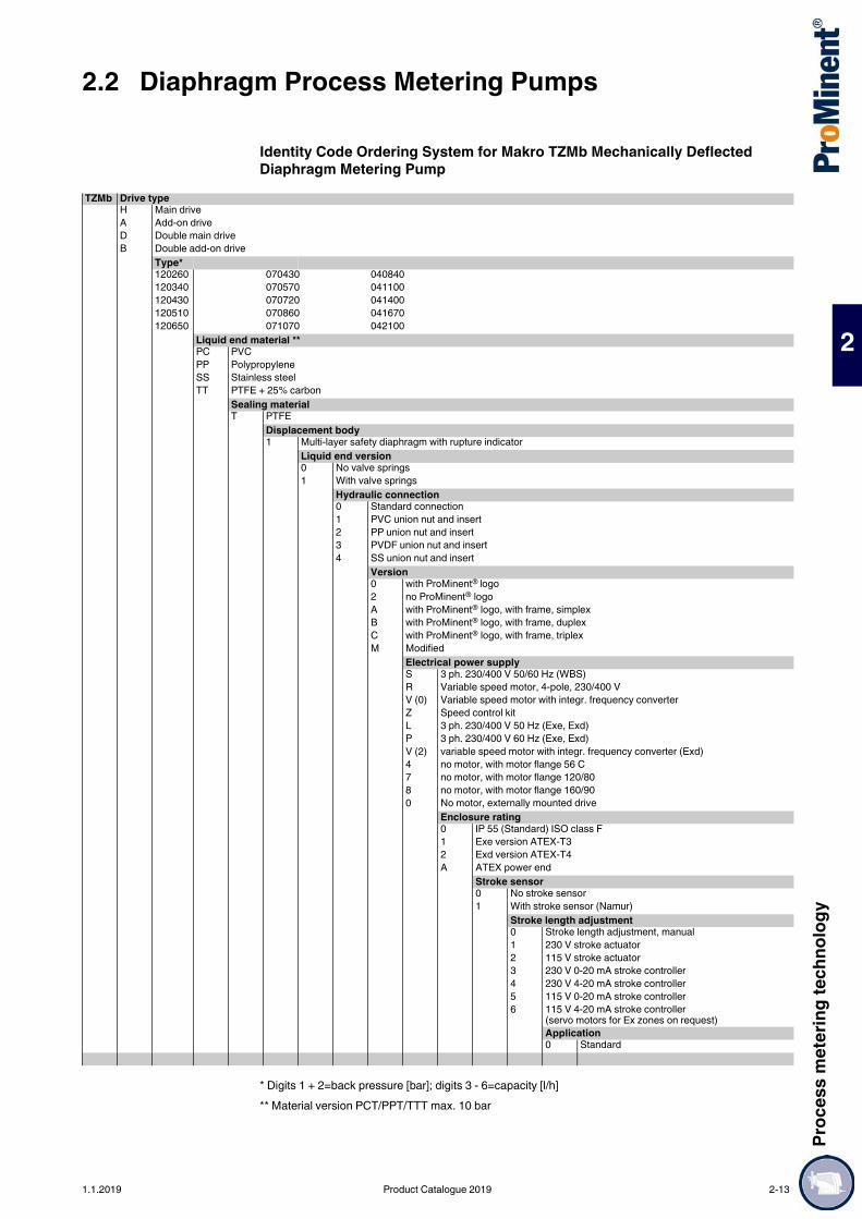
Proc
ess m
eter
ing te
chno
logy
2.2 Diaphragm Process Metering Pumps
2
Identity Code Ordering System for Makro TZMb Mechanically Deflected Diaphragm Metering Pump
* Digits 1 + 2=back pressure [bar]; digits 3 - 6=capacity [l/h]** Material version PCT/PPT/TTT max. 10 bar
TZMb Drive typeH Main driveA Add-on driveD Double main driveB Double add-on drive
Type*120260 070430 040840120340 070570 041100120430 070720 041400120510 070860 041670120650 071070 042100
Liquid end material **PC PVCPP PolypropyleneSS Stainless steelTT PTFE + 25% carbon
Sealing materialT PTFE
Displacement body1 Multi-layer safety diaphragm with rupture indicator
Liquid end version0 No valve springs1 With valve springs
Hydraulic connection0 Standard connection1 PVC union nut and insert2 PP union nut and insert3 PVDF union nut and insert4 SS union nut and insert
Version0 with ProMinent® logo2 no ProMinent® logoA with ProMinent® logo, with frame, simplexB with ProMinent® logo, with frame, duplexC with ProMinent® logo, with frame, triplexM Modified
Electrical power supplyS 3 ph. 230/400 V 50/60 Hz (WBS)R Variable speed motor, 4-pole, 230/400 VV (0) Variable speed motor with integr. frequency converterZ Speed control kitL 3 ph. 230/400 V 50 Hz (Exe, Exd)P 3 ph. 230/400 V 60 Hz (Exe, Exd)V (2) variable speed motor with integr. frequency converter (Exd)4 no motor, with motor flange 56 C7 no motor, with motor flange 120/808 no motor, with motor flange 160/900 No motor, externally mounted drive
Enclosure rating0 IP 55 (Standard) ISO class F1 Exe version ATEX-T32 Exd version ATEX-T4A ATEX power end
Stroke sensor0 No stroke sensor1 With stroke sensor (Namur)
Stroke length adjustment0 Stroke length adjustment, manual1 230 V stroke actuator2 115 V stroke actuator3 230 V 0-20 mA stroke controller4 230 V 4-20 mA stroke controller5 115 V 0-20 mA stroke controller6 115 V 4-20 mA stroke controller
(servo motors for Ex zones on request)Application0 Standard
1.1.2019 Product Catalogue 2019 2-13

2.2 Diaphragm Process Metering PumpsPr
oces
s met
ering
tech
nolog
y
2
Motor Data
Motor data sheets can be requested for more information. Motors for Sigma basic pumps, special motors or special motor flanges are available on request.The motors are designed in compliance with the Ecodesign Directive 2009/125/EC.
Information for use in areas at risk from explosionOnly use pumps with the appropriate labelling in line with the ATEX Directive 2014/34/EU in premises at risk from explosion. Ensure that the explosion group, category and degree of protection specified on the label corresponds to or is better than the conditions prevalent in the intended field of application.
Identity code specification
Power supply Remarks
S 3-phase, IP 55 220 – 240 V/380 – 420 V250 – 280 V/440 – 480 V
50 Hz60 Hz
0.75 kW
R 3-phase, IP 55 230 V/400 V 50/60 Hz 1.5 kW with PTC, speed adjustment range 1:20 with external fan 1-phase 230 V; 50/60 Hz
V0 1-phase, IP 55 230 V ±5 % 50/60 Hz 1.1 kW Variable speed motor with integrated frequency converter
L1 3-phase,II 2G Ex h IIC T3 Gb X
220 – 240 V/380 – 420 V 50 Hz 0.75 kW
L2 3-phase,II 2G Ex h IIC T4 Gb X
220 – 240 V/380 – 420 V 50 Hz 0.75 kW with PTC, speed control range 1:5
P1 3-phase,II 2G Ex h IIC T3 Gb X
250 – 280 V/440 – 480 V 60 Hz 0.75 kW
P2 3-phase,II 2G Ex h IIC T4 Gb X
250 – 280 V/440 – 480 V 60 Hz 0.75 kW with PTC, speed control range 1:5
V2 3-phase,II 2G Ex h IIC T4 Gb X
400 V ±10% 50/60 Hz 1.5 kW Ex-variable speed motor with integrated frequency converter
2-14 Product Catalogue 2019 1.1.2019

Proc
ess m
eter
ing te
chno
logy
2.2 Diaphragm Process Metering Pumps
2
Spare PartsThe spare parts kit generally includes the wear parts for the liquid ends.
Spare Parts Kits for Diaphragm Metering Pump Makro TZ (TZMb)
Identity Code: 120260, 120340, 120430, 120510, 120650
Identity Code: 070430, 070570, 070720, 070860, 071070
Identity Code: 040840, 041100, 041400, 041670, 042100
Multi-Layer Metering Diaphragm for TZMbProMinent multi-layer safety diaphragm with diaphragm rupture warning system and PTFE Teflon coating on the wetted side.
1 Metering diaphragm (multi-layer safety diaphragm)1 Suction valve complete1 Discharge valve complete2 Valve balls (DN 32/DN 40 with plate and spring)1 Complete sealing set (O-rings or flat seals, valve seats, valve seat bushings)
Liquid end Materials in contact with the medium
Order no.
FM 650 - DN 25 PCT, PPT, TTT – 1025164SST – 1022896SST without valves cpl. 1022895
Liquid end Materials in contact with the medium
Order no.
FM 1100 - DN 32 PCT, PPT, TTT – 1025167SST – 1022917SST without valves cpl. 1022916
Liquid end Materials in contact with the medium
Order no.
FM 2100 - DN 40 PCT, PPT, TTT – 1025169SST – 1022930SST without valves cpl. 1022929
Pump type Order no.Identity code: 120260, 120340, 120430, 120510, 120650; Makro TZ FM 650
1022887
Identity code: 070430, 070570, 070720, 070860, 071070; Makro TZ FM 1100
1022900
Identity code: 040840, 041100, 041400, 041670, 042100; Makro TZ FM 2100
1022921
1.1.2019 Product Catalogue 2019 2-15

2.2 Diaphragm Process Metering PumpsPr
oces
s met
ering
tech
nolog
y
2
Spare Parts Kits for Diaphragm Metering Pump Makro TZ (TZMa)
Identity Code: 120190, 120254, 120317, 120381
Identity Code: 060397, 060529, 060661, 060793
Identity Code: 030750, 031000, 031250, 031500, 031875, 031050 , 031395, 031740, 032100, 032500
PTFE Metering Diaphragms for TZMaProMinent® DEVELOPAN® metering diaphragms with a generously-sized steel core vulcanised into fibre reinforced EPDM, with a PTFE Teflon coating on the process-wetted side.
Information for use in areas at risk from explosionOnly use pumps with the appropriate labelling in line with the ATEX Directive 2014/34/EU in premises at risk from explosion. Ensure that the explosion group, category and degree of protection specified on the label corresponds to or is better than the conditions prevalent in the intended field of application.
Liquid end Materials in contact with the medium
Order no.
FM 260 - DN 20 PP – 910452P – 910455T – 910458S without valves cpl. 910475S – 910461
Liquid end Materials in contact with the medium
Order no.
FM 530 - DN 25 PP – 910453P – 910456T – 910459S without valves cpl. 910476S – 910462
Liquid end Materials in contact with the medium
Order no.
FM 1500/2100 - DN 40 PP – 1001573P – 1001574T – 1001575S without valves cpl. 1001577S – 1001576
Pump type Order no.Identity code: 100190, 120190, 100254, 100317, 120317, 100381, 120381; Makro TZ FM 260
811471
Identity code: 060397, 060529, 060661, 060793; Makro TZ FM 530 811472Identity code: 030750, 031000, 031250, 031500, 031050, 031395, 031740, 032100, 032500; Makro TZ FM 1500/FM 2100
811473
2-16 Product Catalogue 2019 1.1.2019

Proc
ess m
eter
ing te
chno
logy
2.2 Diaphragm Process Metering Pumps
2
It is not possible to do more with a mechanically deflected diaphragmCapacity range of single head pump: 1,540 – 4,000 l/h; 4 bar
The diaphragm metering pump Makro/ 5 (M5Ma), together with the Makro/ 5 hydraulic diaphragm and plunger metering pumps, form a range of drive mechanisms with stroke lengths of 20 and/or 50 mm. This covers the capacity range from 38 to 6,000 l/h at 320 – 4 bar. A wide range of power end versions is available for use in areas at risk from explosion with ATEX certification.
Your benefitsProcess reliability:
Metering reproducibility is better than ± 2% within the 30-100% stroke length range under defined conditions and with correct installation.
Excellent flexibility: The modular construction with single and double head versions permits a wide range of applications,
with the double head designs being operated in push-pull mode It is possible to combine up to 4 metering units, even with different pump capacities, in multiple pump
systems 5 different gear ratios are available Customised designs are available on request
Technical Details Stroke length: 0-20 mm, Rod force: 10,000 N Stroke length adjustment range: 0 – 100% Stroke length adjustment: manually by means of a manual adjustment wheel and scaled display in 0.5%
increments (optionally with electric actuator or control drive) Metering reproducibility is better than ± 2% within the 30 – 100% stroke length range under defined
conditions and with correct installation. Observe the information in the operating instructions Wetted materials: Polypropylene, PVC, PTFE+25% carbon, stainless steel 1.4571, special materials
are available on request A wide range of power end versions is available: Three-phase standard motors, motors for use in areas
at risk from explosion and different flange designs for use in customer-specific motors Degree of protection: IP 55 Salt water-resistant, acrylic resin-coated cast iron housing For reasons of safety, provide suitable overload protection mechanisms during the installation of all
mechanically deflected diaphragm metering pumps
Field of application Volume-proportional metering of chemicals/additives in water treatment Metering of reactants and catalysts in the chemical industry Level-dependent metering of additives in industrial production engineering
2.2.3 Diaphragm Metering Pump Makro/ 5
The diaphragm metering pump Makro/ 5 is used to meter reactants and catalysts in the chemical industry. Thanks to its modular construction, it can adapt outstandingly to the actual requirements of each application.
pk_2_099Makro/ 5 M5Ma
pk_2_093
pk_2_098Makro/ 5 externally mounted pump
pk_2_095Makro/ 5 double head pump
1.1.2019 Product Catalogue 2019 2-17

2.2 Diaphragm Process Metering PumpsPr
oces
s met
ering
tech
nolog
y
2
Technical Data
Stainless steel version: Shipping weight 340 kgThe permissible admission pressure on the intake side is approx. 50% of the maximum permissible back pressure.
Materials in Contact With the Medium
Motor Data
Motor data sheets can be requested for more information. Motors for Sigma basic pumps, special motors or special motor flanges are available on request.The motors are designed in compliance with the Ecodesign Directive 2009/125/EC.
Information for use in areas at risk from explosionOnly use pumps with the appropriate labelling in line with the ATEX Directive 2014/34/EU in premises at risk from explosion. Ensure that the explosion group, category and degree of protection specified on the label corresponds to or is better than the conditions prevalent in the intended field of application.
Type M5Ma
With 1500 rpm motor at 50 Hz With 1800 rpm motor at 60 Hz Suctionlift
Connection, suction/discharge side
Shippingweight
Delivery rate atmax. back pressure
Max.stroke rate
Delivery rate atmax. back pressure
Max.stroke rate
bar l/h ml/stroke
Strokes/min
psi l/h gph(US)
Strokes/min
m WC G–DN kg
041540 4 1,540 427 60 58 1,822 481 71 3.0 2 3/4–50 320041900 4 1,900 427 75 58 2,254 595 89 3.0 2 3/4–50 320042600 4 2,600 427 103 58 3,104 820 123 3.0 2 3/4–50 320043400 4 3,400 427 133 58 4,064 1,074 159 3.0 2 3/4–50 320044000 4 4,000 427 156 58 – – – 3.0 2 3/4–50 320
DN 50 plate valvesLiquid end Suction/discharge valve Seals Valve plates/valve spring Valve seats
PPT Polypropylene Polypropylene PTFE Ceramic/ Hast. C + CTFE** PTFE PCT PVC PVC PTFE Ceramic/ Hast. C + CTFE** PTFE TTT PTFE with carbon PTFE with carbon PTFE Ceramic/ Hast. C + CTFE** PTFE SST Stainless steel mat. no.
1.4571/1.4404Stainless steel mat. no. 1.4571/1.4404 PTFE Stainless steel mat. no. 1.4404/
Hast. CPTFE
DEVELOPAN® metering diaphragm with PTFE coating.** The valve spring is coated with CTFE (similar to PTFE)
Special versions on request.
Identity code specification
Power supply Remarks
S 3-phase, IP 55 220 – 240 V/380 – 420 V250 – 280 V/440 – 480 V
50 Hz60 Hz
3 kW
R 3-phase, IP 55 230 V/400 V 50/60 Hz 3 kW with PTC, speed control range 1:5L1 3-phase, II 2G Ex h IIC T3 Gb X 220 – 240 V/380 – 420 V 50 Hz 3.6 kWL2 3-phase, II 2G Ex h IIC T4 Gb X 220 – 240 V/380 – 420 V 50 Hz 4 kW with PTC, speed control range 1:5P1 3-phase, II 2G Ex h IIC T3 Gb X 250 – 280 V/440 – 480 V 60 Hz 3.6 kWP2 3-phase, II 2G Ex h IIC T4 Gb X 250 – 280 V/440 – 480 V 60 Hz 4 kW with PTC, speed control range 1:5
2-18 Product Catalogue 2019 1.1.2019
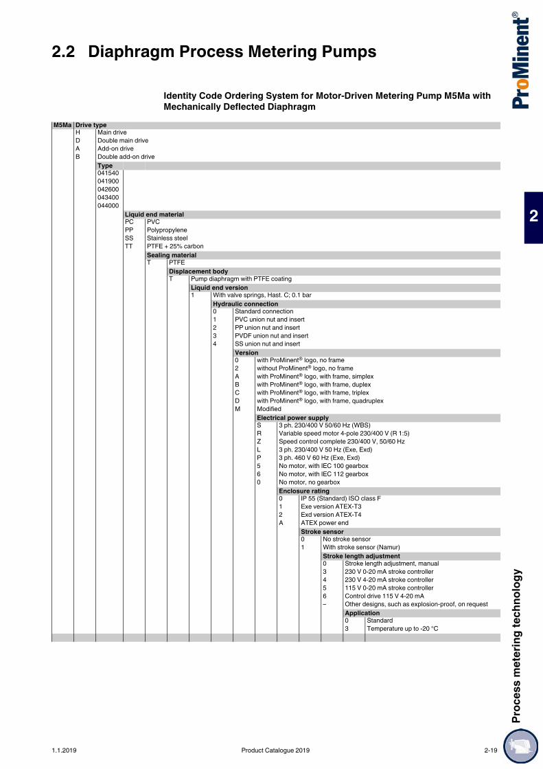
Proc
ess m
eter
ing te
chno
logy
2.2 Diaphragm Process Metering Pumps
2
Identity Code Ordering System for Motor-Driven Metering Pump M5Ma with Mechanically Deflected Diaphragm
M5Ma Drive typeH Main driveD Double main driveA Add-on driveB Double add-on drive
Type041540041900042600043400044000
Liquid end materialPC PVCPP PolypropyleneSS Stainless steelTT PTFE + 25% carbon
Sealing materialT PTFE
Displacement bodyT Pump diaphragm with PTFE coating
Liquid end version1 With valve springs, Hast. C; 0.1 bar
Hydraulic connection0 Standard connection1 PVC union nut and insert2 PP union nut and insert3 PVDF union nut and insert4 SS union nut and insert
Version0 with ProMinent® logo, no frame2 without ProMinent® logo, no frameA with ProMinent® logo, with frame, simplexB with ProMinent® logo, with frame, duplexC with ProMinent® logo, with frame, triplexD with ProMinent® logo, with frame, quadruplexM Modified
Electrical power supplyS 3 ph. 230/400 V 50/60 Hz (WBS)R Variable speed motor 4-pole 230/400 V (R 1:5)Z Speed control complete 230/400 V, 50/60 HzL 3 ph. 230/400 V 50 Hz (Exe, Exd)P 3 ph. 460 V 60 Hz (Exe, Exd)5 No motor, with IEC 100 gearbox6 No motor, with IEC 112 gearbox0 No motor, no gearbox
Enclosure rating0 IP 55 (Standard) ISO class F1 Exe version ATEX-T32 Exd version ATEX-T4A ATEX power end
Stroke sensor0 No stroke sensor1 With stroke sensor (Namur)
Stroke length adjustment0 Stroke length adjustment, manual3 230 V 0-20 mA stroke controller4 230 V 4-20 mA stroke controller5 115 V 0-20 mA stroke controller6 Control drive 115 V 4-20 mA– Other designs, such as explosion-proof, on request
Application0 Standard3 Temperature up to -20 °C
1.1.2019 Product Catalogue 2019 2-19

2.2 Diaphragm Process Metering PumpsPr
oces
s met
ering
tech
nolog
y
2
Spare Parts Kits for Diaphragm Metering Pump Makro/ 5 HMThe replacement part kit in general includes wear parts for the liquid ends.
PTFE Metering DiaphragmsDEVELOPAN® diaphragm made of EPDM with woven fabric inlay, large-area, vulcanised aluminium core and PTFE-Teflon layer on the side in contact with the medium.
1 Metering diaphragm1 Suction valve compl.1 Discharge valve compl.2 Valve plate and Hast. C spring1 Seal kit complete (envelope rings, valve seat/valve seat bushing)
Liquid end Order no.FM 4000 PCT – 1008172FM 4000 PPT – 1008171FM 4000 TTT – 1008173FM 4000 SST without valves cpl. 1008174
Order no.Metering diaphragm for Makro/ 5 FM 4000 1009023
2-20 Product Catalogue 2019 1.1.2019

Proc
ess m
eter
ing te
chno
logy
2.3 Hydraulic Diaphragm Metering Pumps
2
2.3Hydraulic Diaphragm Metering Pumps
For flexible metering with excellent process reliability in the medium pressure range.Capacity range of single head pump: 3 – 72 l/h; 100 – 25 bar
The Hydro/ 2 hydraulic diaphragm metering pump (HP2a), together with the Hydro/ 3 and Hydro/ 4 pumps, represents an integrated product range with stroke lengths of 15 and/or 20 mm. This covers the capacity range from 3 to 1,450 l/h at 100 – 7 bar. A wide range of power end versions is available for use in areas at risk from explosion with ATEX certification. The Hydro product range is designed to comply with API 675 among others.
Your benefitsExcellent process safety and reliability: PTFE multi-layer diaphragm with integral diaphragm rupture warning system Integral hydraulic relief valve Metering reproducibility is better than ± 1% within the 20-100% stroke volume range under defined
conditions and with proper installationExcellent flexibility: The modular construction with single and double head versions permits a wide range of applications,
with the double head designs being operated in push-pull mode It is possible to combine up to 5 metering units, even with different pump capacities, in multiple pump
systems 5 different gear ratios are available
Technical Details Stroke length: 15 mm, Rod force: 2,000 N Stroke volume adjustment range: 0 – 100% Stroke volume adjustment: manually by scaled rotary dial (optionally with electric actuator or control
drive) Metering reproducibility is better than ± 1% in the 20 to 100% stroke volume range under defined
conditions and with correct installation PTFE multi-layer diaphragm with electric diaphragm rupture warning system via a contact Integrated hydraulic relief and bleed valve Wetted materials: PVDF, PTFE+25% carbon, stainless steel 1.4571, Hastelloy C. A wide range of power end versions is available: Three-phase or 1-phase AC motor, motors for use in
areas at risk from explosion, different flange designs for use of customer-specific motors Degree of protection: IP 55 Design in compliance with API 675 among others
Field of application Oil and gas industry Volume-proportional metering of chemicals/additives in the treatment of boiler feed water Metering of reactants and catalysts in the chemical industry Level-dependent metering of auxiliary agents in industrial production engineering, for instance hot wax
metering in the production of adhesive strips
2.3.1 Hydraulic Diaphragm Metering Pump Hydro/ 2
As an extremely robust hydraulic diaphragm metering pump, the Hydro/ 2 meets the most exacting safety requirements. Its modular construction, with either one or two dosing heads, 4 gear ratios, 2 dosing head sizes and 3 dosing head materials, offers a very high degree of flexibility in terms of areas of application.
pk_2_074Hydro
pk_2_073Hydro double head pump
P_HY_0040_SW1Hydro externally mounted pump
P_PZ_0001_SW1Hydro triplex pump
1.1.2019 Product Catalogue 2019 2-21

2.3 Hydraulic Diaphragm Metering PumpsPr
oces
s met
ering
tech
nolog
y
2
Technical Data
Materials in Contact With the Medium
* not for areas at risk from explosion
Motor Data
Motor data sheets can be requested for more information. Motors for Sigma basic pumps, special motors or special motor flanges are available on request.The motors are designed in compliance with the Ecodesign Directive 2009/125/EC.
Information for use in areas at risk from explosionOnly use pumps with the appropriate labelling in line with the ATEX Directive 2014/34/EU in premises at risk from explosion. Ensure that the explosion group, category and degree of protection specified on the label corresponds to or is better than the conditions prevalent in the intended field of application.
Type HP2a
With 1500 rpm motorat 50 Hz
With 1800 rpm motorat 60 Hz
Suctionlift
Perm. pre-pressure
suctionside
Connection on suction/pressure side
Shippingweight
PlungerØ
Delivery rate atmax. back
pressure
Max.stroke
rate
Delivery rate atmax. back
pressure
Max.stroke
rate bar l/h ml/
strokeStrokes/
min psi l/h/gph
(US)Strokes/
min m WC bar G-DN kg mm
100003* 100 3 0.8 60 1,450 3.6/1.0 72 3.0 5 Rp 1/4* 31 16100006* 100 6 0.8 125 1,450 7.0/1.8 150 3.0 5 Rp 1/4* 31 16100007* 100 7 0.8 150 1,450 8.0/2.1 180 3.0 5 Rp 1/4* 31 16100009* 100 9 0.8 187 1,450 11.0/2.9 224 3.0 5 Rp 1/4* 31 16100010* 100 10 0.8 212 – – 3.0 5 Rp 1/4* 31 16064007 64 7 2.0 60 928 8.4/2.2 72 3.0 5 G 3/4-10 31 18064015 64 15 2.0 125 928 18.0/4.8 150 3.0 5 G 3/4-10 31 18064018 64 18 2.0 150 928 21.0/5.5 180 3.0 5 G 3/4-10 31 18064022 64 22 2.0 187 928 26.0/6.9 224 3.0 5 G 3/4-10 31 18064025 64 25 2.0 212 – – 3.0 5 G 3/4-10 31 18025019 25 19 5.3 60 362 23.0/6.1 72 3.0 5 G 3/4-10** 31 26025040 25 40 5.3 125 362 48.0/12.7 150 3.0 5 G 3/4-10** 31 26025048 25 48 5.3 150 362 58.0/15.3 180 3.0 5 G 3/4-10** 31 26025060 25 60 5.3 187 362 72.0/19.0 224 3.0 5 G 3/4-10** 31 26025068 25 68 5.3 212 – – 3.0 5 G 3/4-10** 31 26
Version PVDF max. 25 bar.* Version SST/HCT with double ball valve, valve connector on the suction-pressure with female thread Rp 1/4 and external thread G 3/4 - DN 10** HV design with G1 - DN 15 connector
Material Dosing head Suction/pressure connector Seals/ball seat BallsSST Stainless steel 1.4571/1.4404 Stainless steel 1.4581 PTFE/ZrO2 (DN 15 – stainless steel 1.4404) CeramicPVT* PVDF (polyvinylidene fluoride) PVDF (polyvinylidene fluoride) PTFE/PTFE CeramicHCT Hastelloy C Hastelloy C PTFE/Hastelloy C CeramicTTT PTFE + 25 % carbon PVDF (polyvinylidene fluoride) PTFE/PTFE Ceramic
Identity code specification
Power supply Remarks
S 3-phase, IP 55 220 – 240 V/380 – 420 V250 – 280 V/440 – 480 V
50 Hz60 Hz
0.37 kW
T 3-phase, IP 55 220 – 240 V/380 – 420 V265 – 280 V/440 – 480 V
50 Hz60 Hz
0.37 kW with PTC, speed control range 1:5
R 3-phase, IP 55 230 V/400 V 50/60 Hz 0.37 kW with PTC, speed adjustment range 1:20 with external fan 1-phase 230 V; 50/60 Hz
V0 1-phase, IP 55 230 V ±10% 50/60 Hz 0.37 kW Variable speed motor with integrated frequency converter
L1 3-phase, II 2G Ex h IIC T3 Gb X 220 – 240 V/380 – 420 V 50 Hz 0.37 kWL2 3-phase, II 2G Ex h IIC T4 Gb X 220 – 240 V/380 – 420 V 50 Hz 0.37 kW with PTC, speed control range 1:5P1 3-phase, II 2G Ex h IIC T3 Gb X 254 – 277 V/440 – 480 V 60 Hz 0.37 kWP2 3-phase, II 2G Ex h IIC T4 Gb X 254 – 277 V/440 – 480 V 60 Hz 0.37 kW with PTC, speed control range 1:5V2 3-phase, II 2G Ex h IIC T4 Gb X 400 V ±10% 50/60 Hz 0.55 kW Ex-variable speed motor with integrated
frequency converter
2-22 Product Catalogue 2019 1.1.2019

Proc
ess m
eter
ing te
chno
logy
2.3 Hydraulic Diaphragm Metering Pumps
2
Identity Code Ordering System HP2a
* PVT max. 25 bar
HP2a Drive typeH Main driveD Main drive, double-head versionE Main drive for add on driveF Main drive, double-head version for add-on driveA Add-on driveB Double-head version add-on driveT Triplex comprising 3 power ends and 3 identical heads
Type* bar l/h bar l/h bar l/h
100003 100 3 064007 64 7 025019 25 19100006 100 6 064015 64 15 025040 25 40100007 100 7 064018 64 18 025048 25 48100009 100 9 064022 64 22 025060 25 60100010 100 10 064025 64 25 025068 25 68
Liquid end materialSS Stainless steelPV PVDF (only for 025019 - 025068, 064007 - 064025)HC Hastelloy CTT PTFE + 25% carbon
Sealing material*T PTFE
Displacement body*0 Standard multi-layer diaphragm with rupture signalling facility
Liquid end version0 No valve springs (standard)1 With valve springsD Double ball valve (only for SST and HCT)H HV version (for 025019 – 025060 only, for SST only)
Hydraulic connection0 Standard threaded connectorE With DIN ISO flangeF With ANSI flange
Version0 with ProMinent® logo1 without ProMinent® logoM Modified
Electrical power supplyS 3 ph, 230/400 V, 50/60 Hz, 0,37 kWT 3 ph, 230/400 V, 50/60 Hz, with PTCR 3 ph, Variable speed motor, 230 V/400 V, 0.37 kWV (0) Variable speed motor with integrated frequency converterZ 1 ph, Variable speed control set, 230 V, 50/60 HzL 3 ph, 230/400 V, 50 Hz (Exe, Exd), 0.37 kWP 3 ph, 265/400 V, 60 Hz (Exe, Exd), 0.37 kWV (2) Variable speed motor with integr. frequency converter (Exd)1 no motor, with motor flange B 14, size 2003 no motor, with motor flange B5, size 1604 no motor, with motor flange NEMA 56 C0 Add on drive
Enclosure rating0 IP 55 (standard)1 Exe motor version ATEX-T32 Exde motor version ATEX-T4A ATEX power end
Stroke sensor0 No stroke sensor (standard)1 Stroke sensor (for explosion-proof applications)
Stroke length adjustment0 Manual (standard)1 With stroke positioning motor, 230 V/50/60 Hz2 With stroke positioning motor, 115 V/60 HzA With stroke control motor 0...20 mA 230 V/50/60 HzB With stroke control motor 4...20 mA 230 V/50/60 HzC With stroke control motor 0...20 mA 115 V/60 HzD With stroke control motor 4...20 mA 115 V/60 Hz
Hydraulic oil0 Standard1 Food grade2 Low temperature to -25 °C3 Low temperature Zone 2
1.1.2019 Product Catalogue 2019 2-23

2.3 Hydraulic Diaphragm Metering PumpsPr
oces
s met
ering
tech
nolog
y
2
Spare PartsThe spare parts kit generally includes the wear parts for the liquid ends.Scope of delivery with SST/HCT material version
Scope of delivery with PVT material version
Spare parts kits for Hydro/ 2Applies to identity code: Type 100010, 100009, 100007, 100006, 100003, 064025, 064022, 064018, 064015, 064007
Applies to identity code: Type 025068, 025060, 025048, 025040, 025019
PTFE/1.4404 Metering Diaphragms for Hydro/ 2
Diaphragms PTFE/Hastelloy C Coated for Hydro/ 2
Base for Hydro hydraulic diaphragm metering pumps
1 Diaphragm2 Valve balls1 Sealing set, complete
1 Diaphragm1 Suction valve, complete1 Discharge valve, complete2 Valve balls1 Sealing set, complete
Liquid end Materials in contact with the medium
Order no.
FMH 25 - DN 10 PVT – 1005548SST – 1005549SST for double ball valves 1029260HCT – 1009571SST with valves cpl. 1005550
Liquid end Materials in contact with the medium
Order no.
FMH 60 - DN 10 PVT – 1005552SST – 1005553SST for double ball valves 1005555HCT – 1009573SST with valves cpl. 1005554SST (HV-Ausführung) with valves, complete
(DN 15)1019812
Liquid end Order no.FMH 25 Applies to identity code (SST): 100010, 100009,
100007, 100006, 100003, 064025, 064022, 064018, 064015, 064007
1005545
FMH 60 Applies to identity code (SST): 026068, 025060, 025048, 025040, 025019
1005546
Liquid end Order no.FMH 25 Applies to identity code (PVT/HCT): 064025, 064022,
064018, 064015, 0640071006481
FMH 60 Applies to identity code: 025068, 025060, 025048, 025040, 025019
1006482
P_PZ_0010_SW1
Order no.Base for Hydro/ 2, dimensions: 300 x 160 x 128 mm (LxWxH) 1005660
2-24 Product Catalogue 2019 1.1.2019

Proc
ess m
eter
ing te
chno
logy
2.3 Hydraulic Diaphragm Metering Pumps
2
For flexible metering with excellent process reliability in the medium pressure range.Capacity range of single head pump: 10 – 180 l/h; 100 – 25 bar
The Hydro/ 3 hydraulic diaphragm metering pump (HP3a), together with the Hydro/ 2 and Hydro/ 4 pumps, represents an integrated product range with stroke lengths of 15 and/or 20 mm. This covers the capacity range from 3 to 1,450 l/h at 100 – 7 bar. A wide range of power end versions is available for use in areas at risk from explosion with ATEX certification. The Hydro product range is designed to comply with API 675 among others.
Your benefitsExcellent process safety and reliability: PTFE multi-layer diaphragm with integral diaphragm rupture warning system Integral hydraulic relief valve Metering reproducibility is better than ± 1% within the 20-100% stroke volume range under defined
conditions and with proper installationExcellent flexibility: The modular construction with single and double head versions permits a wide range of applications,
with the double head designs being operated in push-pull mode It is possible to combine up to 5 metering units, even with different pump capacities, in multiple pump
systems 5 different gear ratios are available Customised designs are available on request
Technical Details Stroke length: 15 mm, Rod force: 4,200 N Stroke volume adjustment range: 0 – 100% Stroke volume adjustment: manually by scaled rotary dial (optionally with electric actuator or control
drive) Metering reproducibility is better than ± 1% in the 20 – 100% stroke volume range under defined
conditions and with correct installation PTFE multi-layer diaphragm with electrical diaphragm rupture warning system via a contact Integrated hydraulic relief and bleed valve Wetted materials: PVDF, PTFE+25% carbon, stainless steel 1.4571, Hastelloy C. A wide range of power end versions is available: Three-phase or 1-phase AC motor, motors for use in
areas at risk from explosion, different flange designs for use of customer-specific motors Degree of protection: IP 55 Design in compliance with API 675 among others
Field of application Oil and gas industry. Volume-proportional metering of chemicals/additives in the treatment of boiler feed water Metering of reactants and catalysts in the chemical industry Level-dependent metering of auxiliary agents in industrial production engineering, for instance hot wax
metering in the production of adhesive strips
2.3.2 Hydraulic Diaphragm Metering Pump Hydro/ 3
The Hydro/ 3 is an extremely robust hydraulic diaphragm metering pump. It meets the most exacting safety requirements. Its modular construction offers extremely good flexibility in terms of application, for example in the oil and gas industry.
pk_2_074Hydro
pk_2_073Hydro double head pump
P_HY_0040_SW1Hydro externally mounted pump
P_PZ_0001_SW1Hydro triplex pump
1.1.2019 Product Catalogue 2019 2-25

2.3 Hydraulic Diaphragm Metering PumpsPr
oces
s met
ering
tech
nolog
y
2
Technical Data
Materials in Contact With the Medium
* not for areas at risk from explosion
Motor Data
Motor data sheets can be requested for more information. Motors for Sigma basic pumps, special motors or special motor flanges are available on request.The motors are designed in compliance with the Ecodesign Directive 2009/125/EC.Information for use in areas at risk from explosionOnly use pumps with the appropriate labelling in line with the ATEX Directive 2014/34/EU in premises at risk from explosion. Ensure that the explosion group, category and degree of protection specified on the label corresponds to or is better than the conditions prevalent in the intended field of application.
Type HP3a
With 1500 rpm motor at 50 Hz With 1800 rpm motor at 60 Hz Suc-tion
lift
Perm. pre-pressure
suctionside
Connection suction/dis-charge side
Ship-ping
weight
Plung-er ØDelivery rate at
max. backpressure
Max.stroke
rate
Delivery rate atmax. back pressure
Max.stroke
rate
bar l/h ml/
strokeStrokes/
min psi l/h/gph (US) Strokes/
min m WC bar G–DN kg mm
100010* 100 10 2.8 60 1,450 12/3.2 72 3.0 5 Rp 3/8–10* 41 22100021* 100 21 2.8 125 1,450 25/6.6 150 3.0 5 Rp 3/8–10* 41 22100025* 100 25 2.8 150 1,450 30/7.9 180 3.0 5 Rp 3/8–10* 41 22100031* 100 31 2.8 187 1,450 37/9.8 224 3.0 5 Rp 3/8–10* 41 22100035* 100 35 2.8 212 1,450 – 3.0 5 Rp 3/8–10* 41 22064019 64 19 5.3 60 928 23/6.1 72 3.0 5 G 3/4–10** 41 26064040 64 40 5.3 125 928 48/12.7 150 3.0 5 G 3/4–10** 41 26064048 64 48 5.3 150 928 58/15.3 180 3.0 5 G 3/4–10** 41 26064060 64 60 5.3 187 928 72/19.0 224 3.0 5 G 3/4–10** 41 26064068 64 68 5.3 212 928 – 3.0 5 G 3/4–10** 41 26025048 25 48 13.4 60 362 58/15.3 72 3.0 5 G 1–15*** 41 38025100 25 100 13.4 125 362 120/31.7 150 3.0 5 G 1–15*** 41 38025120 25 120 13.4 150 362 144/38.0 180 3.0 5 G 1–15*** 41 38025150 25 150 13.4 187 362 180/47.6 224 3.0 5 G 1–15*** 41 38025170 25 170 13.4 212 362 – 3.0 5 G 1–15*** 41 38
Version PVDF max. 25 bar.* Version SST/HCT with double ball valve, valve connector on the suction/discharge side with female thread Rp 3/8 and external thread G
3/4 - DN 10** HV design (SST only) with G 1 - DN 15 connector*** HV design (SST only) with 1 1/4“ DN 20 connector
Material Dosing head Suction/pressure connector Seals/ball seat BallsSST Stainless steel 1.4571/1.4404 Stainless steel 1.4581 PTFE/stainless steel 1.4404 CeramicPVT* PVDF (polyvinylidene fluoride) PVDF (polyvinylidene fluoride) PTFE/PTFE CeramicHCT Hastelloy C Hastelloy C PTFE/Hastelloy C CeramicTTT PTFE + 25 % carbon PVDF (polyvinylidene fluoride) PTFE/PTFE Ceramic
Identity code specification
Power supply Remarks
S 3-phase, IP 55 220 – 240 V/380 – 420 V250 – 280 V/440 – 480 V
50 Hz60 Hz
0.75 kW
T 3-phase, IP 55 220 – 240 V/380 – 420 V265 – 280 V/440 – 480 V
50 Hz60 Hz
0.75 kW with PTC, speed control range 1:5
R 3-phase, IP 55 230 V/400 V 50/60 Hz 0.75 kW with PTC, speed control range 1:20, with external fan 1-phase 230 V; 50/60 Hz
V0 1-phase, IP 55 230 V ±10% 50/60 Hz 0.75 kW Variable speed motor with integrated frequency converter
L1 3-phase, II 2G Ex h IIC T3 Gb X 220 – 240 V/380 – 420 V 50 Hz 0.75 kWL2 3-phase, II 2G Ex h IIC T4 Gb X 220 – 240 V/380 – 420 V 50 Hz 0.75 kW with PTC, speed control range 1:5P1 3-phase, II 2G Ex h IIC T3 Gb X 254 – 277 V/440 – 480 V 60 Hz 0.75 kWP2 3-phase, II 2G Ex h IIC T4 Gb X 254 – 277 V/440 – 480 V 60 Hz 0.75 kW with PTC, speed control range 1:5V2 3-phase, II 2G Ex h IIC T4 Gb X 400 V ±10% 50/60 Hz 0.75 kW Ex-variable speed motor with integrated
frequency converter
2-26 Product Catalogue 2019 1.1.2019

Proc
ess m
eter
ing te
chno
logy
2.3 Hydraulic Diaphragm Metering Pumps
2
Identity Code Ordering System HP3a
* PVT max. 25 bar
HP3a Drive typeH Main driveD Main drive, double-head versionE Main drive for add-on driveF Main drive, double-head version for add-on driveA Add-on driveB Double-head version add-on driveT Triplex comprising 3 power ends and 3 identical heads
Type* bar l/h bar l/h bar l/h
100010 100 10 064019 64 19 025048 25 48100021 100 21 064040 64 40 025100 25 100100025 100 25 064048 64 48 025120 25 120100031 100 31 064060 64 60 025150 25 150100035 100 35 064068 64 68 025170 25 170
Liquid end materialSS Stainless steelPV PVDF (max. 25 bar, only for 025048 - 025170, 064019 - 064068)HC Hastelloy CTT PTFE + 25% carbon
Sealing material*T PTFE
Displacement body*0 Standard multi-layer diaphragm with rupture signalling facility
Liquid end version0 No valve springs (standard)1 With valve springsD Double ball valve (for 100010-100035, 064019-064060, only for SST and HCT)H HV design(for 064019 - 064060, 25048 - 25170, SST only)
Hydraulic connection0 Standard threaded connectorE With DIN ISO flangeF With ANSI flange
Version0 with ProMinent® logo1 without ProMinent® logoM Modified
Electrical power supplyS 3 ph, 230/400 V, 50/60 Hz, 0.75 kWT 3 ph, 230/400 V, 50/60 Hz, with PTCR 3 ph, variable speed motor, 230 V/400 V, 0.75 kWV (0) Variable speed motor with integrated frequency converterZ 1 ph, variable speed control set, 230 V, 50/60 HzL 3 ph, 230/400 V 50 Hz (Exe, Exd), 0.75 kWP 3 ph, 265/440 V 60 Hz (Exe, Exd), 0.75 kWV (2) Variable speed motor with integr. frequency converter (Exd)1 no motor, with motor flange B 14, size 2003 no motor, with motor flange B5, size 1604 no motor, with motor flange NEMA 56 C0 Add on drive
Enclosure rating0 IP 55 (standard)1 Exe motor version ATEX-T32 Exd motor version ATEX-T4A ATEX power end
Stroke sensor0 No stroke sensor (standard)1 Stroke sensor (for explosion-proof applications)
Stroke length adjustment0 Manual (Standard)1 With stroke positioning motor, 230 V/50/60 Hz2 With stroke positioning motor, 115 V/60 HzA With stroke control motor 0-20 mA 230 V/50/60 HzB With stroke control motor 4-20 mA 230 V/50/60 HzC With stroke control motor 0-20 mA 115 V/60 HzD With stroke control motor 4-20 mA 115 V/60 Hz
Hydraulic oil0 Standard1 Food grade2 Low temperature to -25 °C
1.1.2019 Product Catalogue 2019 2-27

2.3 Hydraulic Diaphragm Metering PumpsPr
oces
s met
ering
tech
nolog
y
2
Spare PartsThe spare parts kit generally includes the wear parts for the liquid ends.Scope of delivery with SST/HCT material version
Scope of delivery with PVT material version
Spare parts kits for Hydro/ 3Applies to identity code: Type 100035, 100031, 100025, 100021, 100010, 064068, 064060, 064048, 064040, 064019
Applies to identity code: Type 025170, 025150, 025120, 025100, 025048
Metering Diaphragm PTFE/1.4404 for Hydro/ 3
Diaphragms PTFE/Hastelloy C Coated for Hydro/ 3
Base for Hydro hydraulic diaphragm metering pumps
1 Diaphragm2 Valve balls1 Sealing set, complete
1 Diaphragm1 Suction valve, complete1 Discharge valve, complete2 Valve balls1 Sealing set, complete
Liquid end Materials in contact with the medium
Order no.
FMH 60 - DN 10 PVT – 1005552SST – 1005553SST for double ball valves 1005555HCT – 1009573SST with valves cpl. 1005554SST (HV-Ausführung) with valves, complete (DN 15) 1019812
Liquid end Materials in contact with the medium
Order no.
FMH 150 - DN 15 PVT – 1005556SST – 1005557HCT – 1009575SST with valves cpl. 1005558SST (HV-Ausführung) with valves, complete (DN 20) 1019824
Liquid end Order no.FMH 60 Identity code (SST) 064019, 064040, 064048, 064060,
064068, 100010, 100021, 100025, 100031, 1000351005546
FMH 150 Identity code (SST) 025048, 025100, 025120, 025150, 025170
1005547
Liquid end Order no.FMH 60 Identity code (PVT/HCT) 064019, 064040, 064048,
064060, 064068, 100010, 100021, 100025, 100031, 100035
1006482
FMH 150 Identity code (PVT/HCT) 025048, 025100, 025120, 025150, 025170
1006483
P_PZ_0010_SW1
Order no.Base for Hydro/ 3, dimensions: 324 x 180 x 128 mm (LxWxH) 1005661
2-28 Product Catalogue 2019 1.1.2019

Proc
ess m
eter
ing te
chno
logy
2.3 Hydraulic Diaphragm Metering Pumps
2
For flexible metering with excellent process reliability in the medium pressure range.Capacity range of single head pump: 76 – 1,450 l/h; 40 – 7 bar
The Hydro/ 4 hydraulic diaphragm metering pump (HP4a), together with the Hydro/ 2 and Hydro/ 3 pumps, represents an integrated product range with stroke lengths of 15 and/or 20 mm. This covers the capacity range from 3 to 1,450 l/h at 100 – 7 bar. A wide range of power end versions is available for use in areas at risk from explosion with ATEX certification. The Hydro product range is designed to comply with API 675 among others.
Your benefitsExcellent process safety and reliability: PTFE multi-layer diaphragm with integral diaphragm rupture warning system Integral hydraulic relief valve Metering reproducibility is better than ± 1% in the 20-100% stroke volume range under defined
conditions and with proper installation.Excellent flexibility: The modular construction with single and double head versions permits a wide range of applications,
with the double head designs being operated in push-pull mode It is possible to combine up to 5 metering units, even with different pump capacities, in multiple pump
systems 5 different gear ratios are available Customised designs are available on request
Technical Details Stroke length: 20 mm, Rod force: 5,800 N Stroke volume adjustment range: 0 – 100% Stroke volume adjustment: manually by scaled rotary dial (optionally with electric actuator or control
drive). Metering reproducibility is better than ± 1% in the 20 – 100% stroke volume range under defined
conditions and with correct installation PTFE multi-layer diaphragm with electrical diaphragm rupture warning system via a contact Integrated hydraulic relief and bleed valve Wetted materials: PVDF, PTFE+25% carbon, stainless steel 1.4571, Hastelloy C. A wide range of power end versions is available: Three-phase or 1-phase AC motor, motors for use in
areas at risk from explosion, different flange designs for use of customer-specific motors Degree of protection: IP 55 Design in compliance with API 675 among others
Field of application Oil and gas industry. Volume-proportional metering of chemicals/additives in the treatment of boiler feed water Metering of reactants and catalysts in the chemical industry Level-dependent metering of auxiliary agents in industrial production engineering, for instance hot wax
metering in the production of adhesive strips
2.3.3 Hydraulic Diaphragm Metering Pump Hydro/ 4
The Hydro/ 4 is an extremely robust hydraulic diaphragm metering pump, which meets the most exacting safety requirements – it is equipped as standard with a pressure relief valve and PTFE multi-layer diaphragm with diaphragm rupture warning system. Its modular construction offers extremely good flexibility in terms of applications.
pk_2_074Hydro
pk_2_073Hydro double head pump
P_HY_0040_SW1Hydro externally mounted pump
P_PZ_0001_SW1Hydro triplex pump
1.1.2019 Product Catalogue 2019 2-29

2.3 Hydraulic Diaphragm Metering PumpsPr
oces
s met
ering
tech
nolog
y
2
Technical Data
Materials in Contact With the Medium
* not for areas at risk from explosionMotor Data
Motor data sheets can be requested for more information. Motors for Sigma basic pumps, special motors or special motor flanges are available on request. The motors are designed in compliance with the Ecodesign Directive 2009/125/EC.Information for use in areas at risk from explosionOnly use pumps with the appropriate labelling in line with the ATEX Directive 2014/34/EU in premises at risk from explosion. Ensure that the explosion group, category and degree of protection specified on the label corresponds to or is better than the conditions prevalent in the intended field of application.
Type HP4a
With 1500 rpm motor at 50 Hz With 1800 rpm motor at 60 Hz Suc-tion
lift
Perm. pre-pressure
suctionside
Connection suction/dis-charge side
Ship-ping
weight
Plung-er ØDelivery rate at
max. back pressureMax.
strokerate
Delivery rate atmax. back
pressure
Max.stroke
ratebar l/h ml/
strokeStrokes/
min psi l/h/gph
(US)Strokes/
min m WC bar G–DN kg mm
400075 40 76 17.7 71 580 91/24 86 3 1 G 1 1/2–25 69 40400109 40 109 17.7 103 580 132/35 124 3 1 G 1 1/2–25 69 40400145 40 145 17.7 136 580 174/46 164 3 1 G 1 1/2–25 69 40400200 40 200 17.7 188 580 239/63 225 3 1 G 1 1/2–25 69 40400227 40 227 17.7 214 – – 3 1 G 1 1/2–25 69 40250130 25 130 31.0 71 363 155/41 86 3 1 G 1 1/2–25 69 52250190 25 190 31.0 103 363 230/61 124 3 1 G 1 1/2–25 69 52250250 25 250 31.0 136 363 300/79 164 3 1 G 1 1/2–25 69 52250350 25 350 31.0 188 363 420/111 225 3 1 G 1 1/2–25 69 52250400 25 400 31.0 214 – – 3 1 G 1 1/2–25 69 52160210 16 210 48.7 71 232 250/66 86 3 1 G 1 1/2–25 76 63160300 16 300 48.7 103 232 360/95 124 3 1 G 1 1/2–25 76 63160400 16 400 48.7 136 232 480/127 164 3 1 G 1 1/2–25 76 63160550 16 550 48.7 188 232 660/174 225 3 1 G 1 1/2–25 76 63160625 16 625 48.7 214 – – 3 1 G 1 1/2–25 76 63100330 10 330 78.0 71 145 400/106 86 3 1 G 2–32 87 80100480 10 480 78.0 103 145 580/153 124 3 1 G 2–32 87 80100635 10 635 78.0 136 145 760/201 164 3 1 G 2–32 87 80100880 10 880 78.0 188 145 1,050/277 225 3 1 G 2–32 87 80101000 10 1,000 78.0 214 – – 3 1 G 2–32 87 80070465 7 465 109.0 71 102 560/148 86 3 1 G 2 1/4–40 96 94070670 7 670 109.0 103 102 805/213 124 3 1 G 2 1/4–40 96 94070890 7 890 109.0 136 102 1,070/283 164 3 1 G 2 1/4–40 96 94071230 7 1,230 109.0 188 102 1,450/383 225 3 1 G 2 1/4–40 96 94071400 7 1,400 109.0 214 – – 3 1 G 2 1/4–40 96 94
DN 25 ball valves DN 32/DN 40 plate valvesMaterial Dosing head Suction/pressure connector Seals Valve balls Valve
seatsSeals Valve plates/
valve springsValve seats
SST Stainless steel 1.4404 Stainless steel 1.4404 PTFE Stainless steel 1.4404
PTFE PTFE Stainless steel 1.4404/ Hast. C
PTFE
PVT* PVDF (polyvinylidene fluoride) PVDF (polyvinylidene fluoride) PTFE Glass PTFE PTFE Ceramic/E-CTFE PTFEHCT Hastelloy C Hastelloy C PTFE Hastelloy C PTFE PTFE Hast. C / E-CTFE PTFETTT PTFE + 25 % carbon PVDF (polyvinylidene fluoride) PTFE Glass PTFE PTFE Ceramic/E-CTFE PTFE
Identity code specification
Power supply Remarks
S 3-phase, IP 55 220 – 240 V/380 – 420 V250 – 280 V/440 – 480 V
50 Hz60 Hz
1.1 kW
T 3-phase, IP 55 220 – 240 V/380 – 420 V265 – 280 V/440 – 480 V
50 Hz60 Hz
1.1 kW with PTC, speed control range 1:5
R 3-phase, IP 55 230 V/400 V 50/60 Hz 1.5 kW with PTC, speed control range 1:20, with external fan 1-phase 230 V; 50/60 Hz
V0 3-phase, IP 55 400 V 50/60 Hz 1.5 kW Variable speed motor with integrated frequency converter
L1 3-phase, II 2G Ex h IIC T3 Gb X 220 – 240 V/380 – 420 V 50 Hz 1.1 kWL2 3-phase, II 2G Ex h IIC T4 Gb X 220 – 240 V/380 – 420 V 50 Hz 1.1 kW with PTC, speed control range 1:5P1 3-phase, II 2G Ex h IIC T3 Gb X 254 – 277 V/440 – 480 V 60 Hz 1.1 kWP2 3-phase, II 2G Ex h IIC T4 Gb X 254 – 277 V/440 – 480 V 60 Hz 1.1 kW with PTC, speed control range 1:5V2 3-phase, II 2G Ex h IIC T4 Gb X 400 V ±10% 50/60 Hz 1.5 kW Ex-variable speed motor with integrated
frequency converter
2-30 Product Catalogue 2019 1.1.2019

Proc
ess m
eter
ing te
chno
logy
2.3 Hydraulic Diaphragm Metering Pumps
2
Identity Code Ordering System HP4a
* PVT max. 25 bar
HP4a Drive typeH Main driveD Main drive, double-head versionE Main drive for add-on driveF Main drive, double-head version for add-on driveA Add-on driveB Double-head version add-on driveT Triplex comprising 3 power ends and 3 identical heads
Type* bar l/h bar l/h bar l/h bar l/h bar l/h
400075 40 76 250130 25 130 160210 16 210 100330 10 330 070465 7 465400109 40 109 250190 25 190 160300 16 300 100480 10 480 070670 7 670400145 40 145 250250 25 250 160400 16 400 100635 10 635 070890 7 890400200 40 200 250350 25 350 160550 16 550 100880 10 880 071230 7 1,230400227 40 227 250400 25 400 160625 16 625 101000 10 1,000 071400 7 1,400
Liquid end materialSS Stainless steelPV PVDF HC Hastelloy CTT PTFE + 25% carbon
Sealing materialT PTFE
Displacement body0 Standard multilayer diaphragm with rupture signalling facility
Liquid end version0 No valve springs (standard)1 With valve springs
Hydraulic connection0 Standard threaded connectionE With DIN ISO flangeF With ANSI flange
Version0 with ProMinent® logo1 without ProMinent® logo3 With ProMinent® logo, with electrical overpressure displayM Modified
Electrical power supplyS 3 ph, 230/400 V, 50/60 Hz, 1.1 kWT 3 ph, 230/400 V, 50/60 Hz, with PTCR 3 ph, variable speed motor, 230/400 V, 1.5 kWV (0) Variable speed motor with integrated frequency converterZ 1 ph, variable speed control set, 230 V, 50/60 HzL 3 ph, 230/400 V 50 Hz (Exe, Exd), 1.1 kWP 3 ph, 265/440 V 60 Hz (Exe, Exd), 1.1 kWV (2) Variable speed motor with integr. frequency converter (Exd)1 no motor, with motor flange 2503 no motor, with motor flange B5, size 2004 no motor, with motor flange NEMA 143/145 TC0 Add on drive
Enclosure rating0 IP 55 (standard)1 Exe motor version ATEX-T32 Exd motor version ATEX-T4A ATEX power end
Stroke sensor0 No stroke sensor (standard)1 Stroke sensor (for explosion-proof applications)
Stroke length adjustment0 Manual (Standard)K Manual (outdoor, SS)1 With stroke positioning motor, 230 V/50/60 Hz2 With stroke positioning motor, 115 V/60 HzA With stroke control motor 0-20 mA 230 V/50/60 HzB With stroke control motor 4-20 mA 230 V/50/60 HzC With stroke control motor 0-20 mA 115 V/60 HzD With stroke control motor 4-20 mA 115 V/60 Hz
Hydraulic oil0 Standard1 Food grade2 Low temperature to -25 °C
1.1.2019 Product Catalogue 2019 2-31

2.3 Hydraulic Diaphragm Metering PumpsPr
oces
s met
ering
tech
nolog
y
2
Spare PartsThe spare parts kit generally includes the wear parts for the liquid ends.Scope of delivery with SST/HCT material version
Scope of delivery with PVT material version
Spare parts kits for Hydro/ 4Identity code 250130, 250190, 250250, 250350, 250400
Identity code 160210, 160300, 160400, 160550, 160625
Identity code 100330, 100480, 100635, 100880, 101000
Identity code 0704650, 070670, 070890, 071230, 071400
1 Diaphragm2 Valve balls1 Sealing set, complete
1 Diaphragm1 Suction valve, complete1 Discharge valve, complete2 Valve balls1 Sealing set, complete
Liquid end Materials in contact with the medium
Order no.
FMH 400 - DN 25 PVT – 1043763PVT with valve 1023057SST – 1040812SST with valve 1040813HCT – 1040860
Liquid end Materials in contact with the medium
Order no.
FMH 625 - DN 25 PVT – 1043775PVT with valve 1040863SST – 1040824SST with valve 1040825HCT – 1040861
Liquid end Materials in contact with the medium
Order no.
FMH 1000 - DN 32 PVT – 1043776PVT with valve 1040866SST – 1040826SST with valve 1040827HCT – 1040864
Liquid end Materials in contact with the medium
Order no.
FMH 1400 - DN 40 PVT – 1043777PVT with valve 1040869SST – 1040828SST with valve 1040829HCT – 1040867
2-32 Product Catalogue 2019 1.1.2019

Proc
ess m
eter
ing te
chno
logy
2.3 Hydraulic Diaphragm Metering Pumps
2
Metering Diaphragm PTFE/1.4404 for Hydro/ 4
Diaphragms PTFE/Hastelloy C Coated for Hydro/ 4
Base for Hydro hydraulic diaphragm metering pumps
Liquid end Order no.FMH 400 Identity code (SST) 250130, 250190, 250250,
250350, 2504001040808
FMH 625 Identity code (SST) 160210, 160300, 160400, 160550, 160625
1040809
FMH 1000 Identity code (SST) 100330, 100480, 100635, 100880, 101000
1040810
FMH 1400 Identity code (SST) 0704650, 070670, 070890, 071230, 071400
1040811
Liquid end Order no.FMH 400 Identity code (HCT) 250130, 250190, 250250,
250350, 2504001040874
FMH 625 Identity code (HCT) 160210, 160300, 160400, 160550, 160625
1040875
FMH 1000 Identity code (HCT) 100330, 100480, 100635, 100880, 101000
1040876
FMH 1400 Identity code (HCT) 0704650, 070670, 070890, 071230, 071400
1040877
P_PZ_0010_SW1
Order no.Base for Hydro/ 4, dimensions: 344 x 250 x 120 mm (LxWxH) 1051421
1.1.2019 Product Catalogue 2019 2-33

2.3 Hydraulic Diaphragm Metering PumpsPr
oces
s met
ering
tech
nolog
y
2
Excellent feed rates in the low pressure rangeCapacity range of single pump: 450 – 6,108 l/h, 25 – 6 bar
The Makro/ 5 hydraulic diaphragm metering pump (M5Ha) together with the Makro/ 5 diaphragm and plunger metering pumps form an integrated product range with stroke lengths of 20 and/or 50 mm. This covers the capacity range from 38 to 6,108 l/h at 320 – 4 bar. A wide range of power end versions is available for use in areas at risk from explosion with ATEX certification. The Makro/ 5 product range is designed to comply with API 675 among others.
Your benefitsExcellent process safety and reliability: PTFE multi-layer diaphragm with integral diaphragm rupture warning system Integral hydraulic relief valve Metering reproducibility is better than ± 1% within the 10-100% stroke length range under defined
conditions and with correct installation.Excellent flexibility: The modular construction with single and double head versions permits a wide range of applications,
with the double head designs being operated in push-pull mode It is possible to combine up to 4 metering units, even with different pump capacities, in multiple pump
systems 5 different gear ratios are available Customised designs are available on request
Technical Details Stroke length: 0 – 50 mm, Rod force: 10,000 N Stroke length adjustment range: 0 – 100% Stroke length adjustment: manually by means of a manual adjustment wheel and scaled display
(optionally with electric actuator or control drive) Metering reproducibility is better than ± 1 % within the 10 – 100% stroke length range under defined
conditions and with correct installation PTFE multi-layer diaphragm with electrical diaphragm rupture warning system via a contact Integrated hydraulic relief and bleed valve Wetted materials: PVDF, PTFE+25% carbon, stainless steel 1.4571, special materials are available on
request A wide range of power end versions is available: Three-phase standard motors, motors for use in areas
at risk from explosion and different flange designs for use in customer-specific motors Degree of protection: IP 55 Design in compliance with API 675 among others
Field of application Oil and gas industry. Volume-proportional metering of chemicals/additives in the treatment of boiler feed water Metering of reactants and catalysts in the chemical industry Level-dependent metering of auxiliary agents in industrial production engineering, for instance hot wax
metering in the production of adhesive strips
2.3.4 Hydraulic Diaphragm Metering Pump Makro/ 5
The robust hydraulic diaphragm metering pump Makro/ 5 guarantees outstanding process reliability. Its modular construction offers extremely good flexibility and a large range of power end versions are available.
pk_2_096Makro/ 5 M5Ha
pk_2_097Makro/ 5 M5Ha
pk_2_094Makro/ 5 externally mounted pump
pk_2_092Makro/ 5 double head pump
2-34 Product Catalogue 2019 1.1.2019

Proc
ess m
eter
ing te
chno
logy
2.3 Hydraulic Diaphragm Metering Pumps
2
Control of Makro/5 Hydraulic Diaphragm Metering PumpsMakro/ 5 stroke length controllerControl drive consisting of an actuator with servomotor and integral microprocessor controller for stroke length adjustment via a standard signal. Actuating period approx. 100 sec for 100% stroke length, including 2 limit switches for min./max. position, IP 54 degree of protection. Electrical connection 230 V (±10%), 50/60 Hz, 40 W mechanical stroke length display fitted on the Makro/ 5 power end.Special voltage/higher degrees of protection/explosion protection on request.Version with:Standard signal current input 0/4-20 mA, corresponds to stroke length 0 - -100%; internal switch for manual /automatic operation, key switch for stroke adjustment in manual mode. Actual value output 0/4-20 mA for remote display.
Speed controllers with frequency converter (identity code specification Z)The speed controller (complete) comprises a frequency converter and a variable speed motor (see also identity code specification R). The frequency converter is accommodated in an IP 55 rated protective housing with integral control unit and main switch, suitable for max. motor power 0.37/0.75/1.1 kW.Externally controllable with 0/4-20 mA or 0-10 V corresponding to 0-50 (60) Hz output frequency.Frequency Converters for Speed Control See page
Stroke sensor with Namur signalMounting on the crank drive mechanism of the Makro/ 5 gearbox. For precise measurement of each metering stroke, comprising electronic cams and inductive proximity switches, switching signal according to Namur. In combination with electronic pre-selection meters suitable for batch metering or proportional metering in conjunction with proportional control.Retrospective fitting only possible in the factory.Approved for Ex safety operation with degree of protection EEx ia II C T6.
pk_2_103Variable speed motor with integrated frequency converter
1.1.2019 Product Catalogue 2019 2-35

2.3 Hydraulic Diaphragm Metering PumpsPr
oces
s met
ering
tech
nolog
y
2
Technical Data
Material Version PPT/PCT/TTT max. 10 bar* SST version with G 2 1/2“ thread
Materials in Contact With the Medium
Type M5Ha
With 1500 rpm motor at 50 Hz With 1800 rpm motor at 60 Hz Suc-tion lift
Connection suction/dis-charge side
Ship-ping
weight
Plung-er ØDelivery rate at max.
back pressureMax. stroke
rateDelivery rate at
max. back pressureMax. stroke
rate bar l/h ml/
strokeStrokes/min psi l/h gph
(US)Strokes/
min m WC G–DN kg mm
250450 25 450 125.0 60 362 537 142 72 3.0 G 2–32 320 60250562 25 562 125.0 75 362 671 177 89 3.0 G 2–32 320 60250772 25 772 125.0 103 362 922 244 123 3.0 G 2–32 320 60250997 25 997 125.0 133 362 1,191 315 159 3.0 G 2–32 320 60251170 25 1,170 125.0 156 – – – – – G 2–32 320 60160616 16 616 171.2 60 232 736 194 72 3.0 G 2 1/4–40 320 70160770 16 770 171.2 75 232 920 243 89 3.0 G 2 1/4–40 320 70161058 16 1,058 171.2 103 232 1,264 334 123 3.0 G 2 1/4–40 320 70161366 16 1,366 171.2 133 232 1,633 431 159 3.0 G 2 1/4–40 320 70161602 16 1,602 171.2 156 – – – – 3.0 G 2 1/4–40 320 70120716 12 716 199.0 60 174 855 226 72 3.0 G 2 1/4–40 320 75120895 12 895 199.0 75 174 1,069 282 89 3.0 G 2 1/4–40 320 75121229 12 1,229 199.0 103 174 1,469 388 123 3.0 G 2 1/4–40 320 75121588 12 1,588 199.0 133 174 1,898 501 159 3.0 G 2 1/4–40 320 75121862 12 1,862 199.0 156 – – – – 3.0 G 2 1/4–40 320 75120919 12 919 255.3 60 174 1,098 290 72 3.0 G 2 1/4–40 320 85121148 12 1,148 255.3 75 174 1,372 362 89 3.0 G 2 1/4–40 320 85121577 12 1,577 255.3 103 174 1,885 498 123 3.0 G 2 1/4–40 320 85122037 12 2,037 255.3 133 174 2,435 643 159 3.0 G 2 1/4–40 320 85122389 12 2,389 255.3 156 – 2,856 754 – 3.0 G 2 1/4–40 320 85101345 10 1,345 374.0 60 145 1,607 425 72 3.0 G 2 3/4–50 330 100101680 10 1,680 374.0 75 145 2,008 530 89 3.0 G 2 3/4–50 330 100102310 10 2,310 374.0 103 145 2,761 729 123 3.0 G 2 3/4–50 330 100102980 10 2,980 374.0 133 145 3,562 941 159 3.0 G 2 3/4–50 330 100103500 10 3,500 374.0 156 – – – – 3.0 G 2 3/4–50 330 100062305 6 2,305 641.0 60 87 2,755 728 72 3.0 flange–65* 330 130062880 6 2,880 641.0 75 87 3,443 910 89 3.0 flange–65* 330 130063960 6 3,960 641.0 103 87 4,734 1,251 123 3.0 flange–65* 330 130065110 6 5,110 641.0 133 87 6,108 1,614 159 3.0 flange–65* 330 130066000 6 6,000 641.0 156 – – – – 3.0 flange–65* 330 130
DN 32 - DN65 plate valvesDosing head Suction/discharge valve Seals Valve plates/valve
springsValve seats
PPT Polypropylene Polypropylene PTFE Hastelloy C PTFEPCT PVC PVC PTFE Hastelloy C PTFETTT PTFE with carbon PTFE with carbon PTFE Hastelloy C PTFESST Stainless steel material no. 1.4571/1.4404 Stainless steel material no. 1.4571/1.4404 PTFE Hastelloy C PTFE
Patented multi-layer diaphragm, vacuum-packedSpecial designs available on requestViton® is a registered trademark of DuPont Dow Elastomers
2-36 Product Catalogue 2019 1.1.2019
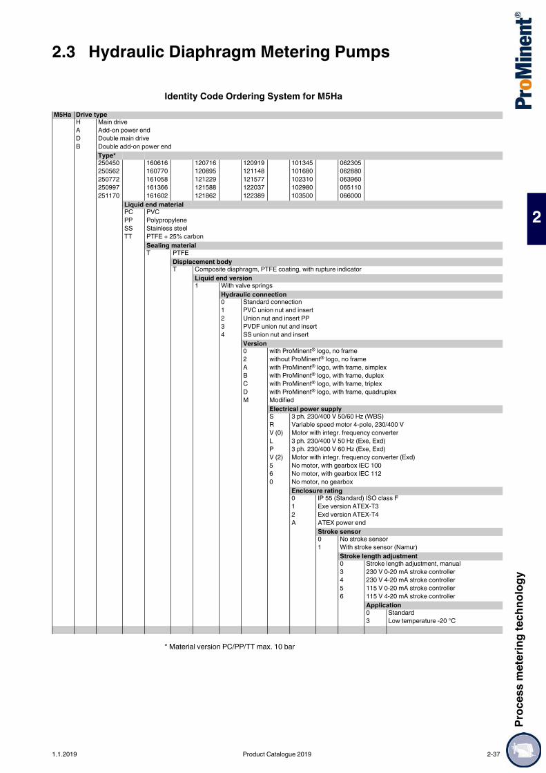
Proc
ess m
eter
ing te
chno
logy
2.3 Hydraulic Diaphragm Metering Pumps
2
Identity Code Ordering System for M5Ha
* Material version PC/PP/TT max. 10 bar
M5Ha Drive typeH Main driveA Add-on power endD Double main driveB Double add-on power end
Type*250450 160616 120716 120919 101345 062305250562 160770 120895 121148 101680 062880250772 161058 121229 121577 102310 063960250997 161366 121588 122037 102980 065110251170 161602 121862 122389 103500 066000
Liquid end materialPC PVCPP PolypropyleneSS Stainless steelTT PTFE + 25% carbon
Sealing materialT PTFE
Displacement bodyT Composite diaphragm, PTFE coating, with rupture indicator
Liquid end version1 With valve springs
Hydraulic connection0 Standard connection1 PVC union nut and insert2 Union nut and insert PP3 PVDF union nut and insert4 SS union nut and insert
Version0 with ProMinent® logo, no frame2 without ProMinent® logo, no frameA with ProMinent® logo, with frame, simplexB with ProMinent® logo, with frame, duplexC with ProMinent® logo, with frame, triplexD with ProMinent® logo, with frame, quadruplexM Modified
Electrical power supplyS 3 ph. 230/400 V 50/60 Hz (WBS)R Variable speed motor 4-pole, 230/400 VV (0) Motor with integr. frequency converterL 3 ph. 230/400 V 50 Hz (Exe, Exd)P 3 ph. 230/400 V 60 Hz (Exe, Exd)V (2) Motor with integr. frequency converter (Exd)5 No motor, with gearbox IEC 1006 No motor, with gearbox IEC 1120 No motor, no gearbox
Enclosure rating0 IP 55 (Standard) ISO class F1 Exe version ATEX-T32 Exd version ATEX-T4A ATEX power end
Stroke sensor0 No stroke sensor1 With stroke sensor (Namur)
Stroke length adjustment0 Stroke length adjustment, manual3 230 V 0-20 mA stroke controller4 230 V 4-20 mA stroke controller5 115 V 0-20 mA stroke controller6 115 V 4-20 mA stroke controller
Application0 Standard3 Low temperature -20 °C
1.1.2019 Product Catalogue 2019 2-37
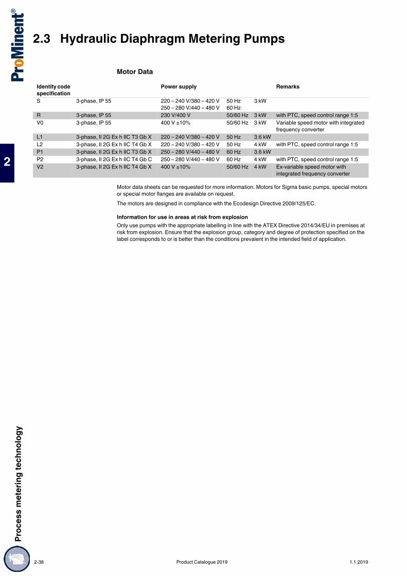
2.3 Hydraulic Diaphragm Metering PumpsPr
oces
s met
ering
tech
nolog
y
2
Motor Data
Motor data sheets can be requested for more information. Motors for Sigma basic pumps, special motors or special motor flanges are available on request.The motors are designed in compliance with the Ecodesign Directive 2009/125/EC.
Information for use in areas at risk from explosionOnly use pumps with the appropriate labelling in line with the ATEX Directive 2014/34/EU in premises at risk from explosion. Ensure that the explosion group, category and degree of protection specified on the label corresponds to or is better than the conditions prevalent in the intended field of application.
Identity code specification
Power supply Remarks
S 3-phase, IP 55 220 – 240 V/380 – 420 V250 – 280 V/440 – 480 V
50 Hz60 Hz
3 kW
R 3-phase, IP 55 230 V/400 V 50/60 Hz 3 kW with PTC, speed control range 1:5V0 3-phase, IP 55 400 V ±10% 50/60 Hz 3 kW Variable speed motor with integrated
frequency converterL1 3-phase, II 2G Ex h IIC T3 Gb X 220 – 240 V/380 – 420 V 50 Hz 3.6 kWL2 3-phase, II 2G Ex h IIC T4 Gb X 220 – 240 V/380 – 420 V 50 Hz 4 kW with PTC, speed control range 1:5P1 3-phase, II 2G Ex h IIC T3 Gb X 250 – 280 V/440 – 480 V 60 Hz 3.6 kWP2 3-phase, II 2G Ex h IIC T4 Gb C 250 – 280 V/440 – 480 V 60 Hz 4 kW with PTC, speed control range 1:5V2 3-phase, II 2G Ex h IIC T4 Gb X 400 V ±10% 50/60 Hz 4 kW Ex-variable speed motor with
integrated frequency converter
2-38 Product Catalogue 2019 1.1.2019

Proc
ess m
eter
ing te
chno
logy
2.3 Hydraulic Diaphragm Metering Pumps
2
Spare PartsThe spare parts kits generally contain the consumable components for the liquid ends.
Spare Parts Kits for Makro/ 5 HMHIdentity code: 250450, 250562, 250772, 250997, 251170
Identity code: 160616, 160770, 161058, 161366, 161602, 120716, 120895, 121229, 121588, 121862, 120919, 121148, 121577, 122037, 122389
Identity code: 101345, 101680, 102310, 102980, 103500
Identity code: 062305, 062880, 063960, 065110, 066000
Metering Diaphragms for Makro/ 5 HMH
1 metering diaphragm1 suction valve set1 discharge valve set1 seal set (O-rings, packing rings, valve seat, valve seat housings)
Liquid end Materials in contact with the medium
Order no.
FMH 60–50 S with 2 valves cpl. 1008170S without valves cpl. 1008169
Liquid end Materials in contact with the medium
Order no.
FMH 70/75/85–50 PPT – 911904PCT – 911902TTT – 911906SST – 911910SST without valves cpl. 911909
Liquid end Materials in contact with the medium
Order no.
FMH 100–50 PP – 1008246P – 1008247T – 1008248S with valves cpl. 1008250S without valves cpl. 1008249
Liquid end Materials in contact with the medium
Order no.
FMH 130–50 PP – 1008251P – 1008252T – 1008253S with valves cpl. 1008265S without valves cpl. 1008264
pk_2_024
Liquid end Order no.FMH 60/70/75/85–50 1007298FMH 100/130–50 1007852
1.1.2019 Product Catalogue 2019 2-39

2.3 Hydraulic Diaphragm Metering PumpsPr
oces
s met
ering
tech
nolog
y
2
Maximum process reliability and flexibility.Capacity range of single head pump: 3 – 7,400 l/h, 400 – 8 bar
The Orlita® Evolution hydraulic diaphragm metering pump range of EF1a, EF2a, EF3a and EF4a form an integrated product range with stroke lengths of 15 to 40 mm. This covers the capacity range of 3 to 7,400 l/h at 400 – 10 bar. A wide range of drive versions is available, including some with ATEX certification for use in Zone 1 or Zone 2 areas at risk from explosion. The Orlita® Evolution product range is designed to comply with API 675.
Your benefitsMaximum process reliability: PTFE multi-layer diaphragm with integral diaphragm rupture warning system Integral hydraulic relief valve The new diaphragm position control protects against impermissible operating statuses (e.g. no damage
in the event of a blockage on the suction or discharge side) Metering reproducibility is better than ± 1% within the 10-100% stroke length adjustment range under
certain defined conditions and with proper installation Continuous bleeding of the oil chamber ensures reliable operationExcellent flexibility: The modular and compact construction with single and multiple pump versions permits a wide range of
applications. In multiple pump systems up to 5 metering units can be combined, including units with different pump capacities
7 gear ratios are available Power end configuration ideal for installation in any position (vertical or horizontal) Customised designs are available on request
Technical Details Stroke length: 0 - 15 mm (Evo 1, Evo 2), 0 - 25 mm (Evo 3), 0 - 40 mm (Evo 4)
Rod force: 2,300 N (Evo 1), 5,400 N (Evo 2), 8,000 N (Evo 3), 15,700 N (Evo 4) Stroke length adjustment range: 0 – 100% Stroke length adjustment: manually by means of a manual adjustment wheel and scaled display
(optionally with electric actuator or control drive) Metering reproducibility is better than ± 1% within the 10 – 100% stroke length range under defined
conditions and with correct installation PTFE multi-layer diaphragm with electrical diaphragm rupture warning system via a contact Integrated hydraulic relief and bleed valve Wetted materials:
Stainless steel 1.4404, special designs available on requestplastics PVC, PVDF, special designs available on request
A wide range of power end versions is available: Three-phase standard motors also for use in areas at risk from explosion, different flange designs for use of customer-specific motors
Degree of protection: IP 55 Design in compliance with API 675 among others
Field of application Oil and gas industry Metering of reactants and catalysts in the chemical industry Volume-proportional metering of chemicals/additives in the treatment of boiler feed water Level-dependent metering of auxiliary agents in industrial production engineering, for instance hot wax
metering in the production of adhesive strips
2.3.5 Hydraulic Diaphragm Metering Pump Orlita® Evolution
The Orlita® Evolution meets the most exacting safety requirements as an extremely robust hydraulic diaphragm metering pump. It is characterised by its PTFE multi-layer diaphragm with integral diaphragm rupture warning / signalling and unique diaphragm position control.
68_52-101_00_01-0a-Evo1_SW1Orlita® Evolution EF1a
68_54-101_00_03-0a-Evo4_SW1Orlita® Evolution EF4a
P_PZ_0008_SW1Orlita® Evolution triplex pump
2-40 Product Catalogue 2019 1.1.2019

Proc
ess m
eter
ing te
chno
logy
2.3 Hydraulic Diaphragm Metering Pumps
2
Orlita® Evolution 1-4 with stainless steel liquid endTechnical data for EF1a single head pump 50 Hz SST
Technical data for EF1a single head pump 60 Hz SST
Note:Abridged presentation of our complete product range. Other piston diameters (8–60 mm) on request
Materials in Contact With the MediumDosing head complete
Ball valve DN 3 – DN 10
Plate valve DN 16
Further material versions and details available on request.
Plung-er Ø
Strokevolume
Theoretical pump capacity in l/h at strokes/min (50 Hz) Max.pres-sure
Efficiencyat
Efficiencyat
Standard type of valve73 [2] 97 [3] 116 [4] 145 [5] 165 [6] 181 [7] 201 [8]
mm ml/stroke
l/h l/h l/h l/h l/h l/h l/h bar 100%pressure
50%pressure
8 0.75 3.3 4.4 5.2 6.6 7.5 8.2 9.1 400 0.43 0.69 DN 310 1.18 5.2 6.9 8.2 10.2 11.7 12.8 14.2 293 0.61 0.79 DN 312 1.70 7.4 9.9 11.8 14.8 16.8 18.4 20.5 203 0.77 0.86 DN 614 2.31 10.1 13.4 16.1 20.1 22.9 25.1 27.8 149 0.62 0.80 DN 617 3.40 14.9 19.8 23.7 29.6 33.7 36.9 41.0 101 0.77 0.88 DN 621 5.20 22.8 30.3 36.2 45.2 51.5 56.5 62.7 66 0.85 0.89 DN 1025 7.36 32.2 42.8 51.2 64.0 72.9 79.9 88.8 47 0.90 0.93 DN 1029 9.91 43.4 57.7 69.0 83.2 98.1 107.6 119.5 35 0.95 0.96 DN 1032 12.06 52.8 70.2 83.9 104.9 119.4 131.0 145.4 29 0.89 0.93 DN 1038 17.01 74.5 99.0 118.4 148.0 168.4 184.7 205.1 20 0.93 0.95 DN 1044 22.81 99.9 132.8 158.8 198.4 225.8 247.7 275.1 15 0.94 0.96 DN 1650 29.45 129.0 171.4 205.0 256.2 291.6 319.9 355.2 12 0.95 0.96 DN 1658 39.63 173.6 230.6 275.8 344.8 392.3 430.4 477.9 9 0.95 0.97 DN 16
Plunger Ø
Strokevolume
Theoretical pump capacity in l/h at strokes/min (60 Hz) Max.pressure
Efficiencyat
Efficiencyat
Standard type of valve88 [2] 117 [3] 140 [4] 175 [5] 199 [6]
mm ml/stroke
l/h l/h l/h l/h l/h bar 100%pressure
50%pressure
8 0.75 4.0 5.3 6.3 7.9 9.0 400 0.43 0.69 DN 310 1.18 6.2 8.3 9.9 12.4 14.1 293 0.61 0.79 DN 312 1.70 9.0 11.9 14.3 17.8 20.3 203 0.77 0.86 DN 614 2.31 12.2 16.2 19.4 24.3 27.6 149 0.62 0.80 DN 617 3.40 18.0 23.9 28.6 35.7 40.6 101 0.77 0.88 DN 621 5.20 27.5 36.5 43.7 54.6 62.1 66 0.85 0.89 DN 1025 7.36 38.9 51.7 61.8 77.3 87.9 47 0.90 0.93 DN 1029 9.91 52.3 69.6 83.2 104.1 118.3 35 0.95 0.96 DN 1032 12.06 63.7 84.7 101.3 126.6 144.0 29 0.89 0.93 DN 1038 17.01 89.8 119.4 142.9 178.6 203.1 20 0.93 0.95 DN 1044 22.81 120.4 160.1 191.6 239.5 272.4 15 0.94 0.96 DN 1650 29.45 155.5 206.7 247.4 309.2 351.6 12 0.95 0.96 DN 1658 39.63 209.2 278.2 332.9 416.1 473.2 9 0.95 0.97 DN 16
Dosing head Diaphragm retaining screw DiaphragmStainless steel Stainless steel 1.4462 PTFE multi-layer diaphragm
Suction/pressure connector
Valve/head seal Valve ball Valve seat Valve housing Clamp ring
DN 3 (double ball) Stainless steel 1.4404
Stainless steel 1.4404
Al2O3 ceramic Stainless steel 1.4404
Stainless steel 1.4404
Hastelloy C4
DN 6 (double ball) Stainless steel 1.4404
Stainless steel 1.4404
SiN ceramic Stainless steel 1.4404
Stainless steel 1.4404
Hastelloy C4
DN 10 (single ball) Stainless steel 1.4404
Stainless steel 1.4404
Al2O3 ceramic Stainless steel 1.4404
Stainless steel 1.4404
Hastelloy C4
Suction/pressure connector
Valve/head seal Valve plate Valve seat Valve housing
DN 16 Stainless steel 1.4404 Stainless steel 1.4571 Stainless steel 1.4462 Stainless steel 1.4404 Stainless steel 1.4404
1.1.2019 Product Catalogue 2019 2-41

2.3 Hydraulic Diaphragm Metering PumpsPr
oces
s met
ering
tech
nolog
y
2
Technical data for EF2a single head pump 50 Hz SST
Technical data for EF2a single head pump 60 Hz SST
Note:Abridged presentation of our complete product range. Other piston diameters (11 – 80 mm) on request.
Materials in Contact With the MediumDosing head complete
Ball valve DN 3 – DN 10
Plate valve DN 16 – DN 20
Further material versions and details available on request.
Plunger Ø
Strokevolume
Theoretical pump capacity in l/h at strokes/min (50 Hz) Max.pres-sure
Efficiencyat
Efficiencyat
Standard type of valve73 [2] 97 [3] 116 [4] 145 [5] 165 [6] 181 [7] 201 [8]
mm ml/stroke
l/h l/h l/h l/h l/h l/h l/h bar 100%pressure
50%pressure
12 1.70 7 10 12 15 17 18 21 400 0.69 0.82 DN 614 2.31 10 13 16 20 22 25 28 351 0.35 0.67 DN 617 3.40 15 20 24 30 34 37 41 238 0.60 0.79 DN 621 5.20 23 30 36 45 51 56 53 156 0.75 0.85 DN 1025 7.36 32 43 51 64 73 80 89 110 0.83 0.89 DN 1029 9.91 43 58 69 86 98 108 120 82 0.90 0.93 DN 1032 12.06 53 70 84 105 119 131 145 67 0.76 0.87 DN 1038 17.01 75 99 118 148 168 185 205 48 0.87 0.92 DN 1044 22.81 100 133 159 198 226 248 275 36 0.90 0.94 DN 1650 29.45 129 171 205 256 292 320 355 28 0.91 0.95 DN 1658 39.63 174 231 276 345 392 430 478 20 0.93 0.96 DN 1670 57.73 253 336 402 502 572 627 696 14 0.94 0.96 DN 20
Plunger Ø
Strokevolume
Theoretical pump capacity in l/h at strokes/min (60 Hz) Max.pres-sure
Efficiencyat
Efficiencyat
Standard type of valve88 [2] 117 [3] 140 [4] 175 [5] 199 [6]
mm ml/stroke
l/h l/h l/h l/h l/h bar 100%pressure
50%pressure
12 1.70 9 12 14 18 20 400 0.69 0.82 DN 614 2.31 12 16 19 24 28 351 0.35 0.67 DN 617 3.40 18 24 29 36 41 238 0.60 0.79 DN 621 5.20 27 37 44 55 62 156 0.75 0.85 DN 1025 7.36 39 52 62 77 88 110 0.83 0.89 DN 1029 9.91 52 70 83 104 118 82 0.90 0.93 DN 1032 12.06 64 85 101 127 144 67 0.76 0.87 DN 1038 17.01 90 119 143 179 203 48 0.87 0.92 DN 1044 22.81 120 160 192 240 272 36 0.90 0.94 DN 1650 29.45 155 207 247 309 352 28 0.91 0.95 DN 1658 39.63 209 278 333 416 473 20 0.93 0.96 DN 1670 57.73 305 405 485 606 689 14 0.94 0.96 DN 20
Dosing head Diaphragm retaining screw DiaphragmStainless steel 1.4404 Stainless steel 1.4462 PTFE multi-layer diaphragm
Suction/pressure connector
Valve/head seal Valve ball Valve seat Valve housing Clamp ring
DN 3 (double ball) Stainless steel 1.4404
Stainless steel 1.4404
Al2O3 ceramic Stainless steel 1.4404
Stainless steel 1.4404
Hastelloy C4
DN 6 (double ball) Stainless steel 1.4404
Stainless steel 1.4404
SiN ceramic Stainless steel 1.4404
Stainless steel 1.4404
Hastelloy C4
DN 10 (double ball) Stainless steel 1.4404
Stainless steel 1.4404
Al2O3 ceramic Stainless steel 1.4404
Stainless steel 1.4404
Hastelloy C4
Suction/pressure connector
Valve/head seal Valve plate Valve seat Valve housing
DN 16/DN 20 Stainless steel 1.4404 Stainless steel 1.4571 Stainless steel 1.4462 Stainless steel 1.4404 Stainless steel 1.4404
2-42 Product Catalogue 2019 1.1.2019

Proc
ess m
eter
ing te
chno
logy
2.3 Hydraulic Diaphragm Metering Pumps
2
Technical data for EF3a single head pump 50 Hz SST
Technical data for EF3a single head pump 60 Hz SST
Note:Abridged presentation of our complete product range. Other piston diameters (14 - 75 mm) on request
Materials in Contact With the MediumDosing head complete
Ball valve DN 6 – DN 10
Plate valve DN 16 – DN 25
Further material versions and details available on request.
Plunger Ø
Strokevolume
Theoretical pump capacity in l/h at strokes/min (50 Hz) Max.pres-sure
Efficiencyat
Efficiencyat
Standard type of valve73 [2] 97 [3] 116 [4] 145 [5] 165 [6] 181 [7] 201 [8]
mm ml/stroke
l/h l/h l/h l/h l/h l/h l/h bar 100%pressure
50%pressure
17 5.67 24 32 39 49 56 61 68 352 0.68 0.83 DN 622 9.50 41 55 66 82 93 103 114 210 0.87 0.93 DN 625 12.27 53 71 85 106 121 133 148 163 0.86 0.92 DN 1030 17.67 77 102 123 174 192 192 213 113 0.92 0.95 DN 1034 22.70 99 132 158 197 225 247 274 88 0.90 0.94 DN 1638 28.35 123 164 197 247 280 308 343 71 0.93 0.95 DN 1644 38.01 165 220 265 331 376 413 459 53 0.95 0.97 DN 2050 49.09 214 285 342 427 485 534 593 41 0.97 0.98 DN 2058 66.05 287 383 460 575 653 718 798 30 0.98 0.99 DN 2063 77.93 341 454 542 678 772 846 940 26 0.97 0.98 DN 2570 96.21 419 558 670 837 951 1,046 1,163 21 0.98 0.98 DN 2575 110.45 480 640 768 960 1,091 1,201 1,334 18 0.98 0.98 DN 25
Plunger Ø
Strokevolume
Theoretical pump capacity in l/h at strokes/min (60 Hz) Max.pres-sure
Efficiencyat
Efficiencyat
Standard type of valve88 [2] 117 [3] 140 [4] 175 [5] 199 [6]
mm ml/stroke
l/h l/h l/h l/h l/h bar 100%pressure
50%pressure
17 5.67 29 39 47 59 67 352 0.68 0.83 DN 622 9.50 50 67 80 100 113 210 0.87 0.93 DN 625 12.27 64 86 103 129 146 163 0.86 0.92 DN 1030 17.67 93 124 148 186 211 113 0.92 0.95 DN 1034 22.70 120 159 191 238 271 88 0.90 0.94 DN 1638 28.35 149 198 238 298 338 71 0.93 0.95 DN 1644 38.01 200 266 319 399 454 53 0.95 0.97 DN 2050 49.09 258 344 412 515 585 41 0.97 0.98 DN 2058 66.05 347 462 555 694 788 30 0.98 0.99 DN 2063 77.93 411 547 655 818 930 26 0.97 0.98 DN 2570 96.21 505 673 808 1,010 1,148 21 0.98 0.98 DN 2575 110.45 580 773 927 1,159 1,317 18 0.98 0.98 DN 25
Dosing head Diaphragm retaining screw DiaphragmStainless steel 1.4404 Stainless steel 1.4462 PTFE multi-layer diaphragm
Suction/pressure connector
Valve/head seal Valve ball Valve seat Valve housing Clamp ring
DN 6 (double ball) Stainless steel 1.4404
Stainless steel 1.4404
SIN ceramic Stainless steel 1.4404
Stainless steel 1.4404
Hastelloy C4
DN 10 (single ball) Stainless steel 1.4404
Stainless steel 1.4404
Al2O3 ceramic Stainless steel 1.4404
Stainless steel 1.4404
Hastelloy C4
Suction/pressure connector
Valve/head seal Valve plate Valve seat Valve housing
DN 16/DN 25 Stainless steel 1.4404 Stainless steel 1.4571 Stainless steel 1.4462 Stainless steel 1.4404 Stainless steel 1.4404
1.1.2019 Product Catalogue 2019 2-43

2.3 Hydraulic Diaphragm Metering PumpsPr
oces
s met
ering
tech
nolog
y
2
Technical data for EF4a single head pump 50 Hz SST
Technical data for EF4a single head pump 60 Hz SST
Note:Abridged presentation of our complete product range. Additional plunger diameters (22 – 140 mm) on request.Materials in Contact With the MediumDosing head complete
Plate valve
Further material versions and details available on request.
Plung-er Ø
Strokevolume
Theoretical pump capacity in l/h at strokes/min (50 Hz) Max.pres-sure
Efficiencyat
Efficiencyat
Standard type of valve73 [2] 97 [3] 116 [4] 145 [5] 165 [6] 181 [7] 201 [8]
mm ml/stroke
l/h l/h l/h l/h l/h l/h l/h bar 100%pressure
50%pressure
22 15.21 67 89 106 132 151 165 183 400 0.71 0.84 DN 1625 19.63 86 114 137 171 194 213 237 320 0.72 0.85 DN 1630 28.27 124 165 197 246 280 307 341 222 0.73 0.85 DN 1634 36.32 159 211 253 316 360 394 438 172 0.80 0.87 DN 1638 45.36 199 264 316 395 449 493 547 138 0.86 0.90 DN 2044 60.82 266 354 423 529 602 661 733 103 0.90 0.92 DN 2050 78.54 344 457 547 683 778 853 947 80 0.93 0.94 DN 2560 113.10 495 658 787 984 1,120 1,228 1,364 55 0.94 0.95 DN 3270 153.94 674 896 1,071 1,339 1,524 1,672 1,857 40 0.94 0.95 DN 4075 176.71 774 1,028 1,230 1,537 1,749 1,919 2,131 35 0.95 0.96 DN 4086 232.35 1,018 1,352 1,617 2,021 2,300 2,523 2,802 27 0.96 0.97 DN 5090 254.47 1,115 1,481 1,771 2,214 2,519 2,764 3,069 24 0.96 0.97 DN 50
100 314.16 1,376 1,828 2,187 2,733 3,110 3,412 3,789 20 0.97 0.98 DN 50110 380.13 1,665 2,212 2,646 3,307 3,763 4,128 4,584 16 0.98 0.98 DN 50115 415.48 1,820 2,418 2,892 3,615 4,113 4,512 5,011 15 0.98 0.99 DN 65130 530.93 2,325 3,090 3,695 4,619 5,256 5,766 6,403 12 0.99 0.99 DN 65140 615.75 2,697 3,584 4,286 5,357 6,096 6,687 7,426 10 0.99 0.99 DN 65
Plung-er Ø
Strokevolume
Theoretical pump capacity in l/h at strokes/min (60 Hz) Max.pres-sure
Efficiencyat
Efficiencyat
Standard type of valve88 [2] 117 [3] 140 [4] 175 [5] 199 [6]
mm ml/stroke
l/h l/h l/h l/h l/h bar 100%pressure
50%pressure
22 15.21 80 107 128 160 182 400 0.71 0.84 DN 1625 19.63 104 138 165 206 234 320 0.72 0.85 DN 1630 28.27 149 198 237 297 337 222 0.73 0.85 DN 1634 36.32 192 255 305 381 434 172 0.80 0.87 DN 1638 45.36 240 318 381 476 542 138 0.86 0.90 DN 2044 60.82 321 427 511 639 726 103 0.90 0.92 DN 2050 78.54 415 551 660 825 938 80 0.93 0.94 DN 2560 113.10 597 794 950 1,188 1,350 55 0.94 0.95 DN 3270 153.94 813 1,081 1,293 1,616 1,838 40 0.94 0.95 DN 4075 176.71 933 1,241 1,484 1,855 2,110 35 0.95 0.96 DN 4086 232.35 1,227 1,631 1,952 2,440 2,774 27 0.96 0.97 DN 5090 254.47 1,344 1,786 2,138 2,671 3,038 24 0.96 0.97 DN 50
100 314.16 1,659 2,205 2,639 3,299 3,751 20 0.97 0.98 DN 50110 380.13 2,007 2,669 3,193 3,991 4,539 16 0.98 0.98 DN 50115 415.48 2,194 2,917 3,490 4,363 4,961 15 0.98 0.99 DN 65130 530.93 2,803 3,727 4,460 5,575 6,339 12 0.99 0.99 DN 65140 615.75 3,251 4,323 5,172 6,465 7,352 10 0.99 0.99 DN 65
Dosing head Diaphragm retaining screw DiaphragmStainless steel 1.4404 Stainless steel 1.4462 PTFE multi-layer diaphragm
Suction/ pressure connector
Valve/ head seal Valve plate Valve seat Valve housing
DN 16 – DN 65 Stainless steel 1.4404 Stainless steel 1.4571 Stainless steel 1.4462 Stainless steel 1.4404 Stainless steel 1.4404
2-44 Product Catalogue 2019 1.1.2019

Proc
ess m
eter
ing te
chno
logy
2.3 Hydraulic Diaphragm Metering Pumps
2
Orlita® Evolution 1-4 with PVC/PVDF liquid endThe hydraulic diaphragm pump Orlita® Evolution is also available in a “plastic dosing head” version. The chemical resistance of the wetted materials PVC and PVDF to many media enables the even more flexible use of this process-reliable pump in an even greater number of applications.
Technical data for EF1a single head pump 50 Hz PVC/PVDF
Technical data for EF1a single head pump 60 Hz PVC/PVDF
Note:Abridged presentation of our complete product range. Other piston diameters (8 - 60 mm) on request. Other pressures (16 and/or 21 bar) on request.
Materials in Contact With the MediumDosing head complete
Ball valve DN 6 – DN 10
Plate valve DN 16
Further material versions and details available on request.
Plung-er Ø
Strokevolume
Theoretical pump capacity in l/h at strokes/min (50 Hz) Max.pres-sure
Efficiencyat
Efficiencyat
Standard type of valve73 [2] 97 [3] 116 [4] 145 [5] 165 [6] 181 [7] 201 [8]
mm ml/stroke
l/h l/h l/h l/h l/h l/h l/h bar 100%pressure
50%pressure
8 0.75 3.3 4.4 5.2 6.6 7.5 8.2 9.1 16 0.65 0.70 DN 310 1.18 5.2 6.9 8.2 10.2 11.7 12.8 14.2 16 0.81 0.88 DN 312 1.70 7.4 9.9 11.8 14.8 16.8 18.5 20.5 16 0.79 0.82 DN 621 5.20 22.8 30.2 36.2 45.2 51.4 56.4 62.7 16 0.81 0.84 DN 1025 7.36 32.3 42.9 51.2 64.1 72.9 80.0 88.8 16 0.84 0.87 DN 1029 9.91 43.4 57.7 69.0 86.2 98.1 107.6 119.5 16 0.86 0.89 DN 1044 22.81 99.9 132.8 158.8 198.4 225.8 247.7 275.1 10 0.94 0.96 DN 1650 29.45 129.0 171.4 205.0 256.2 291.6 319.9 355.2 10 0.95 0.96 DN 1660 42.41 185.8 246.8 295.2 369.0 419.9 460.6 511.5 8 0.96 0.97 DN 16
Plung-er Ø
Strokevolume
Theoretical pump capacity in l/h at strokes/min (60 Hz) Max.pres-sure
Efficiencyat
Efficiencyat
Standard type of valve88 [2] 117 [3] 140 [4] 175 [5] 199 [6]
mm ml/stroke
l/h l/h l/h l/h l/h bar 100%pressure
50%pressure
8 0.75 4.0 5.3 6.3 7.9 9.0 16 0.65 0.70 DN 310 1.18 6.2 8.3 9.9 12.4 14.1 16 0.81 0.88 DN 312 1.70 9.0 11.9 14.3 17.9 20.3 16 0.79 0.82 DN 621 5.20 27.5 36.5 43.7 54.6 62.1 16 0.81 0.84 DN 1025 7.36 38.9 51.7 61.8 77.3 87.9 16 0.84 0.87 DN 1029 9.91 52.3 69.6 83.2 104.1 118.3 16 0.86 0.89 DN 1044 22.81 120.4 160.1 191.6 239.5 272.4 10 0.94 0.96 DN 1650 29.45 155.5 206.7 247.4 309.2 351.6 10 0.95 0.96 DN 1660 42.41 223.9 297.7 356.2 445.3 506.4 8 0.96 0.97 DN 16
Dosing head Diaphragm retaining screw DiaphragmPVC Hastelloy C PTFEPVDF Hastelloy C PTFE
Suction/pressure connector
Valve/head seal Valve ball Valve seat Valve housing Clamp ring
DN 6 (single ball) PVDF PTFE moulded composite Al2O3 ceramic PTFE PVDF PVDFDN 10 (single ball) PVDF PTFE moulded composite Al2O3 ceramic PTFE PVDF PVDF
Suction/pressure connector
Valve/head seal Valve ball Valve seat Valve housing
DN 16 PVDF PTFE ZrO2 ceramic PTFE PVDF
1.1.2019 Product Catalogue 2019 2-45

2.3 Hydraulic Diaphragm Metering PumpsPr
oces
s met
ering
tech
nolog
y
2
Technical data for EF2a single head pump 50 Hz PVC/PVDF
Technical data for EF2a single head pump 60 Hz PVC/PVDF
Note:Abridged presentation of our complete product range. Other piston diameters on request. Other pressure stages (e.g. 21 bar) on request.
Materials in Contact With the MediumDosing head complete
Ball valve DN 6 – DN 10
Plate valve DN 16
Further material versions and details available on request.
Plunger Ø
Strokevolume
Theoretical pump capacity in l/h at strokes/min (50 Hz) Max.pres-sure
Efficiencyat
Efficiencyat
Standard type of valve73 [2] 97 [3] 116 [4] 145 [5] 165 [6] 181 [7] 201 [8]
mm ml/stroke
l/h l/h l/h l/h l/h l/h l/h bar 100%pressure
50%pressure
11 1.43 6 8 10 12 14 16 17 16 0.66 0.72 DN 612 1.70 7 10 12 15 17 18 21 16 0.79 0.82 DN 621 5.20 23 30 36 45 51 56 63 16 0.81 0.84 DN 1025 7.36 32 43 51 64 73 80 89 16 0.84 0.87 DN 1029 9.91 43 58 69 86 98 108 120 16 0.86 0.89 DN 1044 22.81 100 133 159 198 226 248 275 10 0.94 0.96 DN 1650 29.45 129 171 205 256 292 320 355 10 0.95 0.96 DN 1660 42.41 186 247 295 369 420 460 511 8 0.96 0.97 DN 16
Plunger Ø
Strokevolume
Theoretical pump capacity in l/h at strokes/min (60 Hz) Max.pres-sure
Efficiencyat
Efficiencyat
Standard type of valve88 [2] 117 [3] 140 [4] 175 [5] 199 [6]
mm ml/stroke
l/h l/h l/h l/h l/h bar 100%pressure
50%pressure
11 1.43 8 10 12 15 17 16 0.66 0.72 DN 612 1.70 9 12 14 18 20 16 0.79 0.82 DN 621 5.20 27 37 44 55 62 16 0.81 0.84 DN 1025 7.36 39 52 62 77 88 16 0.84 0.87 DN 1029 9.91 52 70 83 104 118 16 0.86 0.89 DN 1044 22.81 120 160 192 240 272 10 0.94 0.96 DN 1650 29.45 155 207 247 309 352 10 0.95 0.96 DN 1660 42.41 224 298 356 445 506 8 0.96 0.97 DN 16
Dosing head Diaphragm retaining screw DiaphragmPVC Hastelloy C PTFEPVDF Hastelloy C PTFE
Suction/pressure connector
Valve/head seal Valve ball Valve seat
Valve housing
Clamp ring
DN 6 (single ball) PVDF PTFE moulded composite Al2O3 ceramic PTFE PVDF PVDFDN 10 (single ball) PVDF PTFE moulded composite Al2O3 ceramic PTFE PVDF PVDF
Suction/pressure connector
Valve/head seal Valve plate Valve seat Valve housing
DN 16 PVDF PTFE ZrO2 ceramic PTFE PVDF
2-46 Product Catalogue 2019 1.1.2019

Proc
ess m
eter
ing te
chno
logy
2.3 Hydraulic Diaphragm Metering Pumps
2
Technical data for EF3a single head pump 50 Hz PVC/PVDF
Technical data for EF3a single head pump 60 Hz PVC/PVDF
Note:Abridged presentation of our complete product range. Other piston diameters on request. Other pressure stages (e.g. 16 bar) on request.
Materials in Contact With the MediumDosing head complete
Plate valve
Further material versions and details available on request.
Plunger Ø
Strokevolume
Theoretical pump capacity in l/h at strokes/min (50 Hz) Max.pres-sure
Efficiencyat
Efficiencyat
Standard type of valve73 [2] 97 [3] 116 [4] 145 [5] 165 [6] 181 [7] 201 [8]
mm ml/stroke
l/h l/h l/h l/h l/h l/h l/h bar 100%pressure
50%pressure
63 77.93 339 452 542 678 770 848 942 10 0.95 0.96 DN 2567 88.14 386 513 613 767 873 957 1,063 10 0.95 0.96 DN 2570 96.21 419 558 670 837 951 1,046 1,163 10 0.96 0.97 DN 2575 110.45 480 641 769 961 1,092 1,201 1,335 10 0.97 0.98 DN 25
Plunger Ø
Strokevolume
Theoretical pump capacity in l/h at strokes/min (60 Hz) Max.pres-sure
Efficiencyat
Efficiencyat
Standard type of valve88 [2] 117 [3] 140 [4] 175 [5] 199 [6]
mm ml/stroke
l/h l/h l/h l/h l/h bar 100%pressure
50%pressure
63 77.93 409 546 655 818 930 10 0.95 0.96 DN 2567 88.14 465 619 740 925 1,052 10 0.95 0.96 DN 2570 96.21 505 673 808 1,010 1,148 10 0.96 0.97 DN 2575 110.45 583 775 928 1,160 1,319 10 0.97 0.98 DN 25
Dosing head Diaphragm retaining screw DiaphragmPVC Hastelloy C PTFEPVDF Hastelloy C PTFE
Suction/pressure connector
Valve/head seal Valve plate Valve seat Valve housing
DN 25 PVDF PTFE ZrO2 ceramic PTFE PVDF
1.1.2019 Product Catalogue 2019 2-47

2.3 Hydraulic Diaphragm Metering PumpsPr
oces
s met
ering
tech
nolog
y
2
Technical data for EF4a single head pump 50 Hz PVC/PVDF
Technical data for EF4a single head pump 60 Hz PVC/PVDF
Note:Abridged presentation of our complete product range. Other piston diameters on request. Other pressure stages (16 and/or 21 bar) on request.
Materials in Contact With the MediumDosing head complete
Ball valve DN 3 – DN 10
Plate valve
Further material versions and details available on request.
Plunger Ø
Strokevolume
Theoretical pump capacity in l/h at strokes/min (50 Hz) Max.pres-sure
Efficiencyat
Efficiencyat
Standard type of valve
73 [2] 97 [3] 116 [4] 145 [5] 165 [6] 181 [7] 201 [8] mm ml/
stroke l/h l/h l/h l/h l/h l/h l/h bar 100%
pressure50%
pressure70 153.94 674 896 1,071 1,339 1,524 1,672 1,857 10 0.94 0.95 DN 4086 232.35 1,018 1,352 1,617 2,021 2,300 2,523 2,802 10 0.96 0.97 DN 50
110 380.13 1,665 2,212 2,646 3,307 3,763 4,128 4,584 10 0.98 0.98 DN 50140 615.75 2,697 3,584 4,286 5,357 6,096 6,687 7,426 10 0.99 0.99 DN 65
Plunger Ø
Strokevolume
Theoretical pump capacity in l/h at strokes/min (60 Hz) Max.pres-sure
Efficiencyat
Efficiencyat
Standard type of valve
88 [2] 117 [3] 140 [4] 175 [5] 199 [6] mm ml/
stroke l/h l/h l/h l/h l/h bar 100%
pressure50%
pressure70 153.94 813 1,081 1,293 1,616 1,838 10 0.94 0.95 DN 40
110 380.13 2,007 2,669 3,193 3,991 4,539 10 0.98 0.98 DN 50140 615.75 3,251 4,323 5,172 6,465 7,352 10 0.99 0.99 DN 65
86 232.35 1,227 1,631 2,440 2,523 1,952 10 0.96 0.97 DN 50
Dosing head Diaphragm retaining screw DiaphragmPVC Hastelloy C PTFEPVDF Hastelloy C PTFE
Suction/pressure connector
Valve/head seal Valve ball Valve seat Valve housing Clamp ring
DN 25 (single ball) PVDF PTFE moulded composite
Al2O3 ceramic PTFE PVDF PVDF
Suction/pressure connector
Valve/head seal Valve plate Valve seat Valve housing
DN 40 – DN 65 PVDF PTFE ZrO2 ceramic PTFE PVDF
2-48 Product Catalogue 2019 1.1.2019

Proc
ess m
eter
ing te
chno
logy
2.3 Hydraulic Diaphragm Metering Pumps
2
For the smallest quantities at the highest pressuresCapacity range 0.01 – 23 l/h, 400 – 25 bar
With a capacity range of 0.01 – 23 l/h at pressure of up to 400 bar, the hydraulic diaphragm metering pump Evolution mikro EFMa and EHMa is extremely suitable for ultra-precise micro-metering in gas metering and in filling processes of all kinds. It is also used for additive metering in the petrochemical and chemical industry. The Evolution mikro is designed in compliance with API 675, ATEX and FDA.
Your benefitsMaximum process reliability: Precise micro-metering at high pressures Hermetically sealed by PTFE or metal multi-layer safety diaphragm Long service life thanks to its sturdy construction with non-wearing, contactless power end High positioning accuracy (in the micron range) and zero backlash (no overload)Excellent flexibility: Seriously extended adjustment range of 1:200 Universally controllable with electronically integrated overload protection Individual process-dependent metering profiles are possible Space-saving, easy-to-assemble solution
Technical Details Stroke length: 0 – 60 mm Stroke rate: 0 – 240 strokes/min. Precise metering of 0.01 l/h up to a max. of 23 l/h at up to 400 bar Stroke length adjustment range 0 – 100% Metering reproducibility is better than ±1 % in the 10 – 100% stroke length range under defined
conditions and with correct installation PTFE or metal multi-layer safety diaphragm with integral diaphragm rupture signalling Large real volumetric flow adjustment range: 1:200 Wetted materials: Stainless steel 1.4404, special materials are available on request Universal control options, such as analogue, contact, field bus etc. Individual process-dependent metering profiles are possible Space-saving, easy-to-fit solution Degree of protection IP 55 Designs compliant with API 675, ATEX and FDA (on request) are available
Field of application Additive metering in the chemical and petrochemical industry General filling processes in industry Metering of additives in the food industry Universal lab applications Gas metering applications
2.3.6 Hydraulic Diaphragm Metering Pump Evolution mikro
The Evolution mikro is an innovative micro-metering pump for high pressures. The hydraulic diaphragm metering pump is the first of its kind with an electronically regulated direct linear drive. The power end does not contain any mechanical functional elements and thus works virtually maintenance-free.
P_ORL_0058_SW1
1.1.2019 Product Catalogue 2019 2-49

2.3 Hydraulic Diaphragm Metering PumpsPr
oces
s met
ering
tech
nolog
y
2
Technical Data
Scope of delivery Linear motor pump Controller for metering profile management Power unit for power supply 2 m cable for data transmission, optional Switch cabinet for the protection of components
Type EFMa, Type EHMa
Pump capacity at 180 strokes/min. Pump capacity at 240 strokes/min. Suctionlift
Standard type of valve
Shippingweight
PlungerØ
Delivery rate at max.back pressure
Strokerate
Delivery rate at max.back pressure
Strokerate
bar l/h ml/stroke Strokes/min.
bar l/h ml/stroke Strokes/min.
m WC kg mm
01021 10 16.2 1.50 0 – 180 10 21.6 1.50 0 – 240 1 DN 6 25 602521 25 16.0 1.49 0 – 180 25 21.4 1.49 0 – 240 1 DN 6 25 606420 64 15.5 1.44 0 – 180 64 20.7 1.44 0 – 240 1 DN 6 25 610020 100 15.1 1.40 0 – 180 100 20.1 1.40 0 – 240 1 DN 6 25 616004 160 3.5 0.33 0 – 180 160 4.7 0.33 0 – 240 1 DN 3 25 325004 250 3.0 0.28 0 – 180 250 4.0 0.28 0 – 240 1 DN 3 25 332003 320 2.4 0.23 0 – 180 320 3.3 0.23 0 – 240 1 DN 3 25 340003 400 2.2 0.21 0 – 180 400 3.0 0.21 0 – 240 1 DN 3 25 3
2-50 Product Catalogue 2019 1.1.2019

Proc
ess m
eter
ing te
chno
logy
2.3 Hydraulic Diaphragm Metering Pumps
2
Reliable capacity even at high pressureCapacity range of single pump: 0 – 13,000 l/h, 700 – 6 bar
ORLITA® MF hydraulic diaphragm metering pumps (MFS 18 to MFS 1400) with a stroke length of 15 to 60 mm provide a capacity ranging from 0 to 13,000 l/h at 700 – 6 bar. A wide range of drive versions is available, including some for use in Zone 1 or Zone 2 areas at risk from explosion with ATEX certification. The Orlita® MF product range is designed to comply with API 675. Its modular construction permits the free combination of drives, power ends and dosing heads, producing a pump for a range of different feed rates and media operating at different working pressures.
Your benefitsExcellent process safety and reliability: PTFE double diaphragm with integrated diaphragm rupture warning system ensures precise and low-
wear operation despite high pressures The product chamber is hermetically separated from the hydraulic part Integrated hydraulic relief valve and automatic bleed valve for the hydraulic chamber Wear-free, valveless enforced anti-cavitation of the hydraulic leakage guarantees optimum dosing
precision Cone valves for use as suction and/or discharge valves with minimal wear, good self-cleaning and low
pressure loss (NPSHR)Excellent flexibility: The modular construction allows a wide range of uses. In multiple pump systems it is possible to
combine up to 6 metering units, even with different pump capacities. In single pumps the drive arrangement may be either vertical or horizontal.
10 different gear ratios are available Temperature range -40 to +150 °C Customised designs are available on request
Technical Details MfS 18 (MF1a) – Stroke length: 0-15 mm, Rod force: 1,750 N MfS 35 (MF2a) – Stroke length: 0-20 mm, Rod force: 3,500 N MfS 80 (MF3a) – Stroke length: 0-20 mm, Rod force: 14,000 N MfS 180 (MF4a) – Stroke length: 0-40 mm, Rod force: 18,000 N MfS 600 (MF5b) – Stroke length: 0-40 mm, Rod force: 40,000 N MfS 1400 (MF6a) – Stroke length: 0-60 mm, Rod force: 60,000 N Stroke length adjustment range: 0 – 100% in operation and idle Stroke length adjustment: manually by means of a manual adjustment wheel and scaled display
(optionally with electric actuator or control drive) Metering reproducibility is better than ± 1% within the 10 – 100% stroke length range under defined
conditions and with correct installation (API 675) PTFE multi-layer diaphragm with electrical diaphragm rupture warning system via a contact Integrated hydraulic relief and bleed valve Wetted materials: Stainless steel, special designs are available on request A wide range of power end versions is available: Three-phase standard motors, motors for use in areas
at risk from explosion and different flange designs for use in customer-specific motors Degree of protection: IP 55 Temperature range - 40 °C to + 150 °C Suction lift up to 8 m Design in compliance with API 675 among others
Field of application Oil/ gas production (onshore/offshore) Refineries Chemical/Petrochemical industry Pharmaceuticals & cosmetics Food production Packaging industry (bottling pumps)
2.3.7 Hydraulic Diaphragm Metering Pump Orlita® MF
The hydraulic diaphragm metering pump Orlita® MF offers reliable capacities even under high pressure and has a modular construction, therefore has versatile uses. Thanks to its modular design, this pump is tailored to meet your requirements even at very high pump capacities.
P_ORL_050_SW1Orlita® MFS 18/12
P_ORL_051_SW1Orlita® MFS 35/30
P_ORL_052_SW1Orlita® MFS 80/40
P_ORL_053_SW1Orlita® MFS 180/60
P_ORL_054_SW1Orlita® MFS 600b/81
P_ORL_055_SW1Orlita® MFS 1400/46
1.1.2019 Product Catalogue 2019 2-51

2.3 Hydraulic Diaphragm Metering PumpsPr
oces
s met
ering
tech
nolog
y
2
Pressure [bar] depending on the metering volume [l/h] at 50 Hz
Triplex Metering PumpsWith triplex metering pumps, the pressure stroke of each liquid end occurs through 120° of crank travel. This results in a metering flow free of pulsation without the use of elaborate pulsation dampers. This design of process diaphragm pump is preferred in the chemical and petrochemical industries.
Multiplexed Metering PumpsThe Orlita® MF range’s modular construction permits a variable combination of drives, motors and liquid ends e.g. quadruple MF metering pumps with central drive.
P_ORL_056_SW1Orlita® MF3S 180/90-90-90 triplex pump
P_ORL_057_SW1Orlita® MF3S 1400/50 multiple pump
2-52 Product Catalogue 2019 1.1.2019

Proc
ess m
eter
ing te
chno
logy
2.3 Hydraulic Diaphragm Metering Pumps
2
Actuation of ORLITA® MF, MH, PS, DRControl drive consisting of an actuator with servo motor and integral servo controller for stroke length adjustment via a standard signal. Standard signal current input 0/4 – 20 mA, corresponds to stroke length 0 – 100%, switch for manual/automatic operation; key switch for stroke adjustment in manual mode, mechanical status display of actual stroke length value output 0/4 – 20 mA for remote display. Control drives can also be designed with bus systems, like HART, PROFIBUS, Fieldbus Foundation ...
Variable speed motors with integrated frequency converter (identity code specification V)Power supply 1 ph 230 V, 50/60 Hz (up to 3 kW). Externally controllable with 0/4 - 20 mA. The following functions are integrated in the terminal box cover: Start/stop switch Switch for manual/external operation Potentiometer for speed control in manual mode
Speed controllers with frequency converter (identity code specification Z)The frequency converter is accommodated in an IP 55 rated protective housing with integral control unit and main switch, suitable for max. 0.37/0.75 kW motor capacity.Externally controllable with 0/4 - 20 mA or 0 - 10 V corresponding to 0 - 50 (60) Hz output frequency.Integrated control unit with versatile functions, such as switching between external/internal control; frequency input using arrow keys with internal control, multilingual fault message display etc. and motor temperature monitoring (thermistor protection).The speed controller assembly consists of a frequency converter and a variable speed motor.
P_ORL_058_SW1Orlita® MFS 18 with 1-phase control drive 115/230 V
P_ORL_059_SW1Orlita® MFS 35 with 1-phase control drive 115/230 V vertical
P_ORL_060_SW1Orlita® MFS 180 with 3-phase control drive
P_ORL_061_SW1Orlita® MFS 35/12-12-12 with control drives
P_ORL_062_SW1Orlita® MFS 18/7 with Varicon
1.1.2019 Product Catalogue 2019 2-53

2.3 Hydraulic Diaphragm Metering PumpsPr
oces
s met
ering
tech
nolog
y
2
Type of drive
When ordering a multiplexed pump, the main and/or all externally mounted pumps require a separate Identity code.
Materials in Contact With the Medium
Motor Data
For example a triplex pumpe (1.) : MF_aH3......................MF_aAR......................MF_aAR......................
Liquid end Suction/discharge valve housing
Valve seals Valve Valve seat Range
S1 (DIN) 1.4404 None 1.4571 Ceramic 1.4404 DN 3S1 (ANSI) A 316 L N/A A 316 Ti Ceramic A 316 LS1 (DIN) 1.4404 1.4404 1.4571 1.4462 1.4462 ≥ DN6S1 (ANSI) A 316 L A 316 L A 316 Ti Duplex SS Duplex SSS2 (DIN) 1.4462 1.4462 1.4571 1.4462 1.4462 ≥ DN6S2 (ANSI) Duplex SS Duplex SS A 316 Ti Duplex SS Duplex SSS3 (DIN) 1.4539 1.4539 2.4610 1.4539 1.4539 ≥ DN6S3 (ANSI) A904L A904L Hastelloy C A904L A904L
A 50 Hz 3 ph. 230/400 V 3 ph. 500 V 3 ph. 380/660 V3 ph. 400/690 V 3 ph. 415 V
B (adjustable 1:5) 50 Hz 3 ph. 230/400 V 3 ph. 500 V 3 ph. 380/660 V3 ph. 400/690 V 3 ph. 415 V
H 60 Hz 3 ph. 220/380 V 3 ph. 400 VK (adjustable 1:5) 60 Hz 3 ph. 220/380 V 3 ph. 400 V
2-54 Product Catalogue 2019 1.1.2019

Proc
ess m
eter
ing te
chno
logy
2.3 Hydraulic Diaphragm Metering Pumps
2
Technical data for MFS 18 single head pump 50 Hz
Technical data for MFS 18 single head pump 60 Hz
Plunger Ø
Strokevolume
Pump capacity Qth in l/h per pump head at H/min[Identity code characteristic 3 to 9]:
Max.pres-sure
Efficiency at Efficiency at Standard type of valve45 [3] 58 [4] 73 [5] 91 [6] 112 [7] 145 [8] 207 [9]
mm ml/stroke
l/h l/h l/h l/h l/h l/h l/h bar 100%pressure
50%pressure
7 0.58 1.5 2.0 2.5 3.1 3.8 5.0 7.1 400 0.50 0.70 DK DN 38 0.75 2.0 2.6 3.2 4.1 5.0 6.5 9.3 348 0.55 0.72 DK DN 3
10 1.18 3.2 4.1 5.1 6.4 7.8 10.2 14.6 222 0.67 0.79 Ke DN 611 1.43 3.8 4.9 6.2 7.7 9.5 12.4 17.7 184 0.67 0.79 Ke DN 612 1.70 4.6 5.9 7.3 9.2 11.3 14.7 21.0 154 0.84 0.88 Ke DN 614 2.31 6.2 8.0 10.0 12.5 15.4 20.0 28.7 113 0.85 0.88 Ke DN 616 3.02 8.2 10.5 13.1 16.4 20.1 26.2 37.4 87 0.86 0.88 Ke DN 618 3.82 10.3 13.2 16.6 20.7 25.5 33.2 47.4 68 0.87 0.88 Ke DN 620 4.71 12.8 16.4 20.5 25.6 31.5 41.0 58.5 55 0.88 0.89 Ke DN 622 5.70 15.5 19.8 24.8 31.0 38.1 49.6 70.8 46 0.88 0.89 Ke DN 10/625 7.36 20.0 25.6 32.0 40.0 49.2 64.0 91.5 35 0.89 0.89 Ke DN 1027 8.59 23.3 29.8 37.3 46.7 57.4 74.7 106.7 30 0.89 0.89 Ke DN 1029 9.91 26.9 34.4 43.1 53.8 66.3 86.2 123.1 26 0.89 0.89 Ke DN 1030 10.60 28.8 36.9 46.1 57.6 70.9 92.2 131.7 24 0.89 0.89 Ke DN 1036 15.27 41.5 53.1 66.4 83.0 102.1 132.8 189.7 17 0.89 0.89 Ke DN 1640 18.85 51.2 65.6 82.0 102.4 126.1 163.9 234.2 13 0.89 0.89 Ke DN 1644 22.81 62.0 79.3 99.2 124.0 152.6 198.4 283.4 11 0.89 0.90 Ke DN 1650 29.45 80.0 102.4 128.1 160.1 197.1 256.2 366.0 8 0.89 0.90 Ke DN 16
Plunger Ø
Strokevolume
Pump capacity Qth in l/h per pump head at H/min[Identity code characteristic 2 to 8]:
Max.pres-sure
Efficiency at Efficiency at Standard type of valve44 [2] 55 [3] 70 [4] 88 [5] 110 [6] 135 [7] 176 [8]
mm ml/stroke
l/h l/h l/h l/h l/h l/h l/h bar 100%pressure
50%pressure
7 0.58 1.5 1.9 2.4 3.0 3.8 4.6 6.1 400 0.50 0.70 DK DN 38 0.75 1.9 2.4 3.1 3.9 4.9 6.1 7.9 348 0.55 0.72 DK DN 3
10 1.18 3.1 3.8 4.9 6.2 7.7 9.5 12.4 222 0.67 0.79 Ke DN 611 1.43 3.7 4.7 6.0 7.5 9.4 11.5 15.0 184 0.67 0.79 Ke DN 612 1.70 4.4 5.6 7.1 8.9 11.2 13.7 17.9 154 0.84 0.88 Ke DN 614 2.31 6.1 7.6 9.7 12.1 15.2 18.7 24.3 113 0.85 0.88 Ke DN 616 3.02 7.9 9.9 12.7 15.9 19.9 24.5 31.8 87 0.86 0.88 Ke DN 618 3.82 10.0 12.6 16.1 20.1 25.1 31.0 40.3 68 0.87 0.88 Ke DN 620 4.71 12.4 15.5 19.9 24.8 31.1 38.2 49.7 55 0.88 0.89 Ke DN 622 5.70 15.0 18.8 24.0 30.1 37.6 46.3 60.2 46 0.88 0.89 Ke DN 10/625 7.36 19.4 24.3 31.1 38.8 48.6 59.8 77.7 35 0.89 0.89 Ke DN 1027 8.59 22.6 28.3 36.2 45.3 56.6 69.7 90.6 30 0.89 0.89 Ke DN 1029 9.91 26.1 32.7 41.8 52.3 65.3 80.4 104.6 26 0.89 0.89 Ke DN 1030 10.60 27.9 34.9 44.7 55.9 69.9 86.1 111.9 24 0.89 0.89 Ke DN 1036 15.27 40.3 50.3 64.4 80.6 100.7 124.0 161.2 17 0.89 0.89 Ke DN 1640 18.85 49.7 62.2 79.6 99.5 124.4 153.1 199.0 13 0.89 0.89 Ke DN 1644 22.81 60.2 75.2 96.3 120.1 150.5 185.2 240.8 11 0.89 0.90 Ke DN 1650 29.45 77.7 97.1 124.4 155.5 194.3 239.2 311.0 8 0.89 0.90 Ke DN 16
DK Double ball valve, Ke Conical valve
Important note: Abridged presentation of our complete product range. Other types on request Allow for a minimum 10% power reserve when designing in accordance with API All hydraulic performance data is based on water at 20 °C
1.1.2019 Product Catalogue 2019 2-55

2.3 Hydraulic Diaphragm Metering PumpsPr
oces
s met
ering
tech
nolog
y
2
Orlita® MFS18 (MF1a) hydraulic diaphragm metering pump
*For other pump configurations see Type of drive page → 2-54
MF1a Drive typeV1 Main drive vertical* AR Drive module right-handZ1 Main drive central* M Modified **AL Drive module left-hand
Plunger diameter007 7 mm 011 11 mm 016 16 mm 022 22 mm 029 29 mm 040 40 mm008 8 mm 012 12 mm 018 18 mm 025 25 mm 030 30 mm 044 44 mm010 10 mm 014 14 mm 020 20 mm 027 27 mm 036 36 mm 050 50 mm
Stroke rate 50 (60) Hz2 -/44 strokes/min 4 58 (70) Strokes/min 6 91 (110) Strokes/min 8 145 (176) Strokes/min3 45 (55) strokes/min 5 73 (88) Strokes/min 7 112 (135) Strokes/min 9 207 (-) Strokes/min
Liquid end material (including valve materials)S1 Stainless steel (see table, sheet 2)
Temperature of pumped medium0 -10 °C to 80 °C 3 10 °C to 115 °C1 -25 °C to 60 °C 4 10 °C to 150 °C2 -40 °C to 60 °C
Displacer format0 PTFE multi-layer diaphragm1 PTFE multi-layer diaphragm with pressure gauge
Liquid end version0 Standard 2 Standard double valve1 Standard with spring 3 Standard double valve with spring
Hydraulic connection suction sideG Thread DIN/ISO A Flange ANSIN Thread NPT/ANSI D Flange DIN/ISO
Hydraulic connection discharge sideG Thread DIN/ISO A Flange ANSIN Thread NPT/ANSI D Flange DIN/ISO
Version0 no features 2 Liquid end polished1 Liquid end heating 3 Special paint finish
Power connectorA Standard voltage 50 HzB Standard voltage 50 Hz adjustableH Standard voltage 60 HzK Standard voltage 60 Hz adjustable0 Externally mounted pump1 without motor with IEC flange2 without motor with NEMA flange
Electrical protection system / explosion protection0 IP 55 C IP 55 EExde1 IP 56 D IP 56 EExnA IP 55 EExn E IP 56 EExeB IP 55 EExe F IP 56 EExde
Electrical options0 no options1 Stroke sensor
Stroke length adjustment0 manual1 0/4-20 mA without Ex2 0/4-20 mA Ex Zone 23 0/4-20 mA Ex Zone 14 0/4-20 mA without EX offshore5 0/4-20 mA Ex Zone 2 offshore6 0/4-20 mA Ex Zone 1 offshore
Environmental conditions0 -20 °C to 40 °C1 -40 °C to 40 °C2 0 °C to 55 °C
Approvals0 CE1 API 6752 VDMA3 ATEX4 ATEX / API 6755 VDMA / ATEX
** Modified version (M) is possible for each ID character of the identity code.
2-56 Product Catalogue 2019 1.1.2019

Proc
ess m
eter
ing te
chno
logy
2.3 Hydraulic Diaphragm Metering Pumps
2
Technical data for MFS 35 single head pump 50 Hz
Technical data for MFS 35 single head pump 60 Hz
Plung-er Ø
Strokevolume
Pump capacity Qth in l/h per pump head at H/min[Identity code characteristic 3 to 9]:
Max.pres-sure
Efficiency at Efficiency at Standard type of valve45 [3] 58 [4] 73 [5] 91 [6] 112 [7] 145 [8] 207 [9]
mm ml/stroke
l/h l/h l/h l/h l/h l/h l/h bar 100%pressure
50%pressure
7 0.77 2.0 2.6 3.3 4.1 5.1 6.7 9.5 400 0.50 0.70 DK DN 38 1.01 2.7 3.5 4.3 5.4 6.7 8.7 12.4 400 0.50 0.70 DK DN 3
10 1.57 4.2 5.4 6.8 8.5 10.5 13.6 19.5 400 0.50 0.70 Ke DN 611 1.90 5.1 6.6 8.2 10.3 12.7 16.5 23.6 368 0.79 0.85 Ke DN 612 2.26 6.1 7.8 9.8 12.3 15.1 19.6 28.1 309 0.79 0.85 Ke DN 614 3.08 8.3 10.7 13.3 16.7 20.6 26.7 38.2 227 0.81 0.85 Ke DN 616 4.02 10.9 13.9 17.4 21.8 26.9 34.9 49.9 174 0.83 0.86 Ke DN 618 5.09 13.8 17.7 22.1 27.6 34.0 44.2 63.2 137 0.84 0.87 Ke DN 620 6.28 17.0 21.8 27.3 34.1 42.0 54.6 78.0 111 0.86 0.88 Ke DN 622 7.60 20.6 26.4 33.0 41.3 50.8 66.1 94.4 92 0.86 0.88 Ke DN 10/625 9.82 26.6 34.1 42.7 53.3 65.7 85.4 122.0 71 0.87 0.88 Ke DN 1027 11.45 31.1 39.8 49.8 62.2 76.6 99.6 142.3 61 0.87 0.88 Ke DN 1030 14.14 38.4 49.2 61.5 76.8 94.6 122.9 175.7 49 0.88 0.89 Ke DN 1036 20.36 55.3 70.8 88.5 110.6 136.2 177.1 253.0 34 0.88 0.89 Ke DN 1640 25.13 68.3 87.4 109.3 136.6 168.2 218.6 312.3 27 0.89 0.89 Ke DN 1644 30.41 82.6 105.8 132.2 165.3 203.5 264.5 377.9 23 0.89 0.89 Ke DN 1650 39.27 106.7 136.6 170.8 213.5 262.8 341.6 488.0 17 0.89 0.89 Ke DN 1660 56.55 153.7 196.7 245.9 307.4 378.4 491.9 702.8 12 0.89 0.90 Ke DN 16/2565 66.37 180.4 230.9 288.6 360.8 444.1 577.3 824.8 10 0.89 0.90 Ke DN 16/2580 100.53 273.3 349.8 437.3 546.6 672.7 874.6 1,249.4 6 0.89 0.90 Ke DN 25
Plung-er Ø
Strokevolume
Pump capacity Qth in l/h per pump head at H/min[Identity code characteristic 2 to 8]:
Max.pres-sure
Efficiency at Efficiency at Standard type of valve44 [2] 55 [3] 70 [4] 88 [5] 110 [6] 135 [7] 176 [8]
mm ml/stroke
l/h l/h l/h l/h l/h l/h l/h bar 100%pressure
50%pressure
7 0.77 2.0 2.5 3.2 4.0 5.0 6.2 8.1 400 0.50 0.70 DK DN 38 1.01 2.6 3.3 4.2 5.3 6.6 8.1 10.6 400 0.50 0.70 DK DN 3
10 1.57 4.1 5.1 6.6 8.2 10.3 12.7 16.5 400 0.50 0.70 Ke DN 611 1.90 5.0 6.2 8.0 10.0 12.5 15.4 20.0 368 0.79 0.85 Ke DN 612 2.26 5.9 7.4 9.5 11.9 14.9 18.3 23.8 309 0.79 0.85 Ke DN 614 3.08 8.1 10.1 13.0 16.2 20.3 25.0 32.5 227 0.81 0.85 Ke DN 616 4.02 10.6 13.2 16.9 21.2 26.5 32.6 42.4 174 0.83 0.86 Ke DN 618 5.09 13.4 16.7 21.5 26.8 33.5 41.3 53.7 137 0.84 0.87 Ke DN 620 6.28 16.5 20.7 26.5 33.1 41.4 51.0 66.3 111 0.86 0.88 Ke DN 622 7.60 20.0 25.0 32.1 40.1 50.1 61.7 80.2 92 0.86 0.88 Ke DN 10/625 9.82 25.9 32.4 41.4 51.8 64.8 79.7 103.6 71 0.87 0.88 Ke DN 1027 11.45 30.2 37.7 48.3 60.4 75.5 93.0 120.9 61 0.87 0.88 Ke DN 1030 14.14 37.3 46.6 59.7 74.6 93.3 114.8 149.2 49 0.88 0.89 Ke DN 1036 20.36 53.7 67.1 85.9 107.4 134.3 165.3 214.9 34 0.88 0.89 Ke DN 1640 25.13 66.3 82.9 106.1 132.7 165.8 204.1 265.4 27 0.89 0.89 Ke DN 1644 30.41 80.2 100.3 128.4 160.5 200.7 247.0 321.1 23 0.89 0.89 Ke DN 1650 39.27 103.6 129.5 165.8 207.3 259.1 318.9 414.6 17 0.89 0.89 Ke DN 1660 56.55 149.2 186.6 238.8 298.5 373.2 459.3 597.1 12 0.89 0.90 Ke DN 16/2565 66.37 175.2 219.0 280.3 350.4 438.0 539.1 700.8 10 0.89 0.90 Ke DN 16/2580 100.53 265.4 331.7 424.6 530.8 663.5 816.6 1,061.6 6 0.89 0.90 Ke DN 25
DK Double ball valve, Ke Conical valve
Important note: Abridged presentation of our complete product range. Other types on request Allow for a minimum 10% power reserve when designing in accordance with API All hydraulic performance data is based on water at 20 °C
1.1.2019 Product Catalogue 2019 2-57

2.3 Hydraulic Diaphragm Metering PumpsPr
oces
s met
ering
tech
nolog
y
2
Orlita® MFS35 (MF2a) hydraulic diaphragm metering pump
*For further pump configurations see Type of drive page → 2-54
MF2a Drive typeV1 Main drive vertical * AR Drive module right-handZ1 Main drive central * M Modified **AL Drive module left-hand
Plunger diameter007 7 mm 012 12 mm 020 20 mm 030 30 mm 050 50 mm008 8 mm 014 14 mm 022 22 mm 036 36 mm 060 60 mm010 10 mm 016 16 mm 025 25 mm 040 40 mm 065 65 mm011 11 mm 018 18 mm 027 27 mm 044 44 mm
Stroke rate 50 (60) Hz2 -/44 strokes/min 4 58 (70) Strokes/min 6 91 (110) Strokes/min 8 145 (176) Strokes/min3 45 (55) strokes/min 5 73 (88) Strokes/min 7 112 (135) Strokes/min 9 207 (-) Strokes/min
Liquid end material (including valve materials)S1 Stainless steel (see table, sheet 2)
Temperature of pumped medium0 -10 °C to 80 °C 2 -40 °C to 60 °C 4 10 °C to 150 °C1 -25 °C to 60 °C 3 10 °C to 115 °C
Displacer format0 PTFE multi-layer diaphragm1 PTFE multi-layer diaphragm with pressure gauge
Liquid end version0 Standard 2 Standard + double valve1 Standard with spring 3 Standard + double valve with spring
Hydraulic connection suction sideG Thread DIN/ISO A Flange ANSIN Thread NPT/ANSI D Flange DIN/ISO
Hydraulic connection discharge sideG Thread DIN/ISO A Flange ANSIN Thread NPT/ANSI D Flange DIN/ISO
Version0 no features1 Liquid end heating2 Liquid end polished3 Special paint finish
Power connectorA Standard voltage 50 HzB Standard voltage 50 Hz adjustableH Standard voltage 60 HzK Standard voltage 60 Hz adjustable0 Externally mounted pump1 without motor with IEC flange2 without motor with NEMA flange
Electrical protection system / explosion protection0 IP 55 D IP 56 EExn1 IP 56 E IP 56 EExeA IP 55 EExn F IP 56 EExdeB IP 55 EExe K IP 65 EExdeC IP 55 EExde
Electrical options0 no options1 Stroke sensor
Stroke length adjustment0 manual1 0/4-20 mA without Ex2 0/4-20 mA Ex Zone 23 0/4-20 mA Ex Zone 14 0/4-20 mA without EX offshore5 0/4-20 mA Ex Zone 2 offshore6 0/4-20 mA Ex Zone 1 offshore
Environmental conditions0 -20 °C to 40 °C1 -40 °C to 40 °C2 0 °C to 55 °C
Approvals0 CE1 API 6752 VDMA3 ATEX4 ATEX / API 6755 VDMA / ATEX
** Modified design (M) is available with every identity code feature
2-58 Product Catalogue 2019 1.1.2019

Proc
ess m
eter
ing te
chno
logy
2.3 Hydraulic Diaphragm Metering Pumps
2
Technical data for MFS 80 single head pump 50 Hz
Technical data for MFS 80 single head pump 60 Hz
Plunger Ø
Strokevolume
Pump capacity Qth in l/h per pump head at H/min [Identitycode characteristic 4 to 9; F]:
Max.pres-sure
Efficiencyat
Efficiencyat
Standard type of valve
104 [4] 122 [5] 134 [6] 155 [7] 160 [8] 182 [9] 193[F]
mm ml/stroke
l/h l/h l/h l/h l/h l/h l/h bar 100%pressure
50%pressure
16 4.02 25 29 32 37 38 43 46 400 0.75 0.83 Ke DN 620 6.28 39 46 50 58 60 68 72 400 0.75 0.83 Ke DN 622 7.60 47 55 61 70 73 82 87 360 0.79 0.80 Ke DN 10/625 9.82 61 71 79 91 94 107 113 285 0.79 0.85 Ke DN 1027 11.45 71 83 92 106 109 125 132 244 0.81 0.85 Ke DN 1029 13.21 82 96 106 122 126 144 152 211 0.82 0.85 Ke DN 1030 14.14 88 103 113 131 135 154 163 198 0.83 0.86 Ke DN 1036 20.36 126 149 164 189 195 222 235 137 0.85 0.87 Ke DN 1640 25.13 156 184 202 233 241 274 290 111 0.86 0.88 Ke DN 1644 30.41 189 222 245 282 292 331 351 98 0.86 0.88 Ke DN 1646 33.24 207 243 268 309 319 362 384 84 0.86 0.88 Ke DN 1650 39.27 244 287 316 365 377 428 453 71 0.87 0.88 Ke DN 1660 56.55 352 414 455 526 543 617 653 50 0.88 0.89 Ke DN 16/2565 66.37 413 486 535 617 637 724 766 40 0.88 0.89 Ke DN 16/2580 100.53 626 736 810 935 965 1,097 1,161 25 0.89 0.89 Ke DN 25
100 157.08 979 1,150 1,266 1,461 1,508 1,714 1,814 17 0.89 0.89 Ke DN 32
Plunger Ø
Strokevolume
Pump capacity Qth in l/h per pump head at H/min [Identitycode characteristic 3 to 9]:
Max.pres-sure
Efficiencyat
Efficiencyat
Standard type of valve
119 [3] 126 [4] 148 [5] 163 [6] 188 [7] 194 [8] 221 [9] mm ml/
stroke l/h l/h l/h l/h l/h l/h l/h bar 100%
pressure50%
pressure16 4.02 28 30 35 39 45 46 53 400 0.75 0.83 Ke DN 620 6.28 44 47 55 61 70 73 83 400 0.75 0.83 Ke DN 622 7.60 54 57 67 74 85 88 100 360 0.79 0.80 Ke DN 10/625 9.82 70 74 87 96 110 114 130 285 0.79 0.85 Ke DN 1027 11.45 81 86 101 112 129 133 151 244 0.81 0.85 Ke DN 1029 13.21 94 100 117 129 149 153 175 211 0.82 0.85 Ke DN 1030 14.14 101 107 125 138 159 164 187 198 0.83 0.86 Ke DN 1036 20.36 145 154 180 199 229 237 269 137 0.85 0.87 Ke DN 1640 25.13 179 190 223 245 283 292 333 111 0.86 0.88 Ke DN 1644 30.41 217 230 270 297 343 354 402 98 0.86 0.88 Ke DN 1646 33.24 237 251 295 325 375 387 440 84 0.86 0.88 Ke DN 1650 39.27 280 297 349 384 443 457 520 71 0.87 0.88 Ke DN 1660 56.55 404 428 502 553 638 659 749 50 0.88 0.89 Ke DN 16/2565 66.37 474 502 589 649 749 773 879 40 0.88 0.89 Ke DN 16/2580 100.53 718 761 893 983 1,134 1,171 1,332 25 0.89 0.89 Ke DN 25
100 157.08 1,123 1,189 1,396 1,537 1,774 1,830 2,081 17 0.89 0.89 Ke DN 32
Ke Conical valve
Important note: Abridged presentation of our complete product range. Other types on request Allow for a minimum 10% power reserve when designing in accordance with API All hydraulic performance data is based on water at 20 °C
1.1.2019 Product Catalogue 2019 2-59

2.3 Hydraulic Diaphragm Metering PumpsPr
oces
s met
ering
tech
nolog
y
2
Orlita® MFS 80 (MF3a) hydraulic diaphragm metering pump
*For further pump configurations see Type of drive page → 2-54
MF3a Drive typeH1 Main drive horizontal* Z1 Main drive central* AR Drive module right-handV1 Main drive vertical* AL Drive module left-hand M Modified **
Plunger diameter016 16 mm 027 27 mm 040 40 mm 060 60 mm020 20 mm 029 29 mm 044 44 mm 065 65 mm022 22 mm 030 30 mm 046 46 mm 080 80 mm025 25 mm 036 36 mm 050 50 mm 100 100 mm
Stroke rate 50 (60) Hz3 - (119) Strokes/min 7 155 (188) Strokes/min4 104 (126) strokes/min 8 160 (194) Strokes/min5 122 (148) Strokes/min 9 182 (221) strokes/min6 134 (163) Strokes/min F 193 (-) Strokes/min
Liquid end material (including valve materials)S1 Stainless steel (see table, sheet 2)
Temperature of pumped medium0 -10 °C to 80 °C 2 -40 °C to 60 °C 4 10 °C to 150 °C1 -25 °C to 60 °C 3 10 °C to 115 °C
Displacer format0 PTFE multi-layer diaphragm1 PTFE multi-layer diaphragm with pressure gauge
Liquid end version0 Standard 2 Standard + double valve1 Standard with spring 3 Standard + double valve with spring
Hydraulic connection suction sideG Thread DIN/ISO A Flange ANSIN Thread NPT/ANSI D Flange DIN/ISO
Hydraulic connection discharge sideG Thread DIN/ISO A Flange ANSIN Thread NPT/ANSI D Flange DIN/ISO
Version0 no features 2 Liquid end polished1 Liquid end heating 3 Special paint finish
Power connectorA Standard voltage 50 HzB Standard voltage 50 Hz adjustableH Standard voltage 60 HzK Standard voltage 60 Hz adjustable0 Externally mounted pump1 without motor with IEC flange2 without motor with NEMA flange
Electrical protection system / explosion protection0 IP 55 D IP 56 EExn1 IP 56 E IP 56 EExeA IP 55 EExn F IP 56 EExdeB IP 55 EExe K IP 65 EExdeC IP 55 EExde D IP 56 EExn
Electrical options0 no options1 Stroke sensor
Stroke length adjustment0 manual1 0/4-20 mA without Ex2 0/4-20 mA Ex Zone 23 0/4-20 mA Ex Zone 14 0/4-20 mA Ex without EX offshore5 0/4-20 mA Ex Zone 2 offshore6 0/4-20 mA Ex Zone 1 offshore
Environmental conditions0 -20 °C to 40 °C1 -40 °C to 40 °C2 0 °C to 55 °C
Approvals0 CE1 API 6752 VDMA3 ATEX4 ATEX / API 6755 VDMA / ATEX
** Modified design (M) is available with every identity code feature
2-60 Product Catalogue 2019 1.1.2019

Proc
ess m
eter
ing te
chno
logy
2.3 Hydraulic Diaphragm Metering Pumps
2
Technical data for MFS 180 single head pump 50 Hz
Technical data for MFS 180 single head pump 60 Hz
Plunger Ø
Strokevolume
Pump capacity Qth in l/h per pump head at H/min [Identitycode characteristic 4 to 9; F]:
Max.pres-sure
Efficiency at Efficiency at Standard type of valve92 [4] 107 [5] 117 [6] 134 [7] 152 [8] 171 [9] 200 [F]
mm ml/stroke
l/h l/h l/h l/h l/h l/h l/h bar 100%pressure
50%pressure
25 19.63 107 126 138 157 178 201 235 366 0.77 0.83 Ke DN 1630 28.27 155 181 199 226 257 290 339 254 0.81 0.85 Ke DN 1636 40.72 223 262 286 326 370 417 489 176 0.83 0.86 Ke DN 1640 50.27 276 323 353 403 457 515 604 143 0.85 0.87 Ke DN 2544 60.82 334 391 428 488 553 623 730 118 0.85 0.87 Ke DN 2550 78.54 431 505 552 630 714 805 943 91 0.86 0.88 Ke DN 2555 95.03 521 611 668 762 864 974 1,141 75 0.87 0.88 Ke DN 3260 113.10 621 727 796 907 1,029 1,160 1,359 63 0.87 0.89 Ke DN 3265 132.73 729 854 934 1,065 1,207 1,361 1,594 54 0.88 0.89 Ke DN 3270 153.94 845 990 1,083 1,235 1,400 1,579 1,849 46 0.88 0.89 Ke DN 4075 176.71 970 1,137 1,243 1,418 1,608 1,812 2,123 40 0.88 0.89 Ke DN 4080 201.06 1,104 1,293 1,415 1,613 1,829 2,062 2,416 35 0.88 0.89 Ke DN 4085 226.98 1,246 1,460 1,597 1,821 2,065 2,328 2,727 31 0.88 0.89 Ke DN 4090 254.47 1,397 1,637 1,791 2,042 2,315 2,610 3,057 28 0.89 0.89 Ke DN 4095 283.53 1,557 1,824 1,995 2,275 2,590 2,908 3,407 25 0.89 0.89 Pt DN 50
100 314.16 1,725 2,021 2,211 2,521 2,858 3,223 3,775 22 0.89 0.89 Pt DN 50115 415.48 2,281 2,673 2,924 3,334 3,781 4,262 4,992 17 0.89 0.89 Pt DN 65125 490.87 2,696 3,158 3,455 3,939 4,467 5,036 – 14 0.89 0.90 Pt DN 65135 572.56 3,144 3,684 4,030 4,595 5,210 5,874 6,880 12 0.89 0.90 Pt DN 65142 633.47 3,479 4,076 4,458 5,084 5,764 6,499 7,612 11 0.89 0.90 Pt DN 65
Plunger Ø
Strokevolume
Pump capacity Qth in l/h per pump head at H/min [Identitycode characteristic 3 to 9]:
Max.pres-sure
Efficiency at Efficiency at Standard type of valve98 [3] 111 [4] 130 [5] 142 [6] 162 [7] 184 [8] 208 [9]
mm ml/stroke
l/h l/h l/h l/h l/h l/h l/h bar 100%pressure
50%pressure
25 19.63 116 130 153 167 216 244 244 352 0.77 0.83 Ke DN 1630 28.27 167 188 220 241 275 312 352 254 0.81 0.85 Ke DN 1636 40.72 240 271 318 347 396 449 507 176 0.83 0.86 Ke DN 1640 50.27 297 335 392 429 489 555 625 143 0.85 0.87 Ke DN 2544 60.82 359 405 475 519 592 671 757 118 0.85 0.87 Ke DN 2550 78.54 464 523 613 671 765 867 978 91 0.86 0.88 Ke DN 2555 95.03 561 633 742 811 925 1,049 1,183 75 0.87 0.88 Ke DN 3260 113.10 668 753 883 966 1,101 1,249 1,408 63 0.87 0.89 Ke DN 3265 132.73 784 884 1,036 1,134 1,293 1,466 1,652 54 0.88 0.89 Ke DN 3270 153.94 909 1,026 1,202 1,315 1,499 1,700 1,916 46 0.88 0.89 Ke DN 4075 176.71 1,044 1,178 1,380 1,509 1,721 1,951 2,200 40 0.88 0.89 Ke DN 4080 201.06 1,188 1,340 1,570 1,717 1,958 2,220 2,503 35 0.88 0.89 Ke DN 4085 226.98 1,341 1,513 1,772 1,939 2,211 2,507 2,826 31 0.88 0.89 Ke DN 4090 254.47 1,503 1,696 1,987 2,174 2,478 2,810 3,168 28 0.89 0.89 Ke DN 4095 283.53 1,675 1,890 2,214 2,422 2,762 3,131 3,530 25 0.89 0.89 Pt DN 50
100 314.16 1,856 2,094 2,453 2,684 3,060 3,470 3,912 22 0.89 0.89 Pt DN 50115 415.48 2,455 2,769 3,245 3,549 4,047 4,589 5,173 17 0.89 0.89 Pt DN 65125 490.87 2,900 3,272 3,834 4,193 4,781 5,422 – 14 0.89 0.90 Pt DN 65135 572.56 3,383 3,817 4,472 4,891 5,577 6,324 – 11 0.89 0.90 Pt DN 65142 633.47 3,743 4,223 4,947 5,412 6,171 6,997 – 11 0.89 0.90 Pt DN 65
DK Double ball valve, Pt Plate valve
Important note: Abridged presentation of our complete product range. Other types on request Allow for a minimum 10% power reserve when designing in accordance with API All hydraulic performance data is based on water at 20 °C
1.1.2019 Product Catalogue 2019 2-61

2.3 Hydraulic Diaphragm Metering PumpsPr
oces
s met
ering
tech
nolog
y
2
Orlita® MFS 180 (MF4a) hydraulic diaphragm metering pump
*For further pump configurations see Type of drive page → 2-54
MF4a Drive typeH1 Main drive horizontal* AL Drive module left-handV1 Main drive vertical* AR Drive module right-handZ1Main drive central * M Modified **
Plunger diameter025 25 mm 044 44 mm 065 65 mm 085 85 mm 115 115 mm030 30 mm 050 50 mm 070 70 mm 090 90 mm 125 125 mm036 36 mm 055 55 mm 075 75 mm 095 95 mm 135 135 mm040 40 mm 060 60 mm 080 80 mm 100 100 mm 142 142 mm
Stroke rate 50 (60) Hz3 - (98) Strokes/min 5 107 (130) Strokes/min 7 134 (162) Strokes/min 9 171 (208) strokes/min4 92 (111) strokes/min 6 117 (142) Strokes/min 8 152 (184) Strokes/min F 200 (-) Strokes/min
Liquid end material (including valve materials)S1 Stainless steel (see table, sheet 2)
Temperature of pumped medium0 -10 °C to 80 °C 2 -40 °C to 60 °C 4 10 °C to 150 °C1 -25 °C to 60 °C 3 10 °C to 115 °C
Displacer format0 PTFE multi-layer diaphragm1 PTFE multi-layer diaphragm with pressure gauge
Liquid end version0 Standard 2 Standard + double valve1 Standard with spring 3 Standard + double valve with spring
Hydraulic connection suction sideG Thread DIN/ISO A Flange ANSIN Thread NPT/ANSI D Flange DIN/ISO
Hydraulic connection discharge sideG Thread DIN/ISO A Flange ANSIN Thread NPT/ANSI D Flange DIN/ISO
Version0 No features 2 Liquid end polished1 Liquid end heating 3 Special paint finish
Power connectorA Standard voltage 50HzB Standard voltage 50Hz adjustableH Standard voltage 60HzK Standard voltage 60Hz adjustable0 Externally mounted pump1 without motor with IEC flange2 without motor with NEMA flange
Electrical protection system / explosion protection0 IP 55 D IP 56 EExn1 IP 56 E IP 56 EExeA IP 55 EExn F IP 56 EExdeB IP 55 EExe K IP 65 EExdeC IP 55 EExde
Electrical options0 No options1 Stroke sensor
Stroke length adjustment0 Manual1 0/4-20 mA without Ex2 0/4-20 mA Ex Zone 23 0/4-20 mA Ex Zone 14 0/4-20 mA Ex without EX offshore5 0/4-20 mA Ex Zone 2 offshore6 0/4-20 mA Ex Zone 1 offshore
Environmental conditions0 -20 °C to 40 °C1 -40 °C to 40 °C2 0 °C to 55 °C
Approvals0 CE1 API 6752 VDMA3 ATEX4 ATEX / API 6755 VDMA / ATEX
** Modified design (M) is available with every identity code feature
2-62 Product Catalogue 2019 1.1.2019
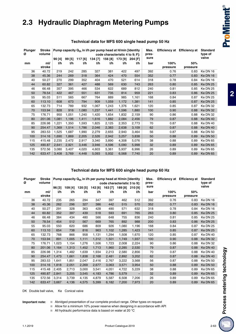
Proc
ess m
eter
ing te
chno
logy
2.3 Hydraulic Diaphragm Metering Pumps
2
Technical data for MFS 600 single head pump 50 Hz
Technical data for MFS 600 single head pump 60 Hz
Plunger Ø
Strokevolume
Pump capacity Qth in l/h per pump head at H/min [Identitycode characteristic 4 to 9; F]:
Max.pres-sure
Efficiency at Efficiency at Standard type of valve90 [4] 99 [5] 117 [6] 134 [7] 156 [8] 173 [9] 204 [F]
mm ml/stroke
l/h l/h l/h l/h l/h l/h l/h bar 100%pressure
50%pressure
36 40.72 219 242 285 327 381 422 497 392 0.76 0.83 Ke DN 1638 45.36 244 269 318 364 424 470 554 352 0.77 0.83 Ke DN 1640 50.27 270 299 352 404 470 521 614 318 0.78 0.84 Ke DN 1644 60.82 327 361 427 488 569 630 743 263 0.80 0.85 Ke DN 2546 66.48 357 395 466 534 622 689 812 240 0.81 0.85 Ke DN 2550 78.54 422 467 551 631 735 814 959 221 0.83 0.86 Ke DN 2555 95.03 511 565 667 764 889 985 1,161 168 0.84 0.87 Ke DN 2560 113.10 608 673 794 909 1,059 1,172 1,381 141 0.85 0.87 Ke DN 2565 132.73 714 789 932 1,067 1,243 1,376 1,621 120 0.85 0.87 Ke DN 3270 153.94 828 916 1,080 1,237 1,441 1,596 1,880 100 0.90 0.88 Ke DN 3275 176.71 950 1,051 1,240 1,420 1,654 1,832 2,159 90 0.86 0.88 Ke DN 3280 201.06 1,081 1,196 1,411 1,616 1,882 2,084 2,456 79 0.87 0.88 Ke DN 4085 226.98 1,221 1,350 1,593 1,825 2,125 2,353 2,773 70 0.87 0.88 Ke DN 4090 254.47 1,369 1,514 1,786 2,046 2,383 2,638 3,109 62 0.87 0.88 Ke DN 4095 283.53 1,525 1,687 1,990 2,279 2,655 2,940 3,464 56 0.87 0.88 Ke DN 50
100 314.16 1,690 1,869 2,205 2,526 2,942 3,257 3,838 50 0.88 0.89 Ke DN 50115 415.48 2,235 2,472 2,917 3,340 3,890 4,308 5,076 38 0.88 0.89 Ke DN 65125 490.87 2,641 2,921 3,446 3,946 4,596 5,090 5,998 32 0.89 0.89 Ke DN 65135 572.56 3,080 3,407 4,020 4,603 5,361 5,937 6,996 26 0.89 0.89 Ke DN 65142 633.47 3,408 3,769 4,448 5,093 5,932 6,568 7,740 20 0.89 0.89 Ke DN 65
Plunger Ø
Strokevolume
Pump capacity Qth in l/h per pump head at H/min [Identitycode characteristic 3 to 9]:
Max.pres-sure
Efficiency at Efficiency at Standard type of valve96 [3] 109 [4] 120 [5] 142 [6] 163 [7] 189 [8] 210 [9]
mm ml/stroke
l/h l/h l/h l/h l/h l/h l/h bar 100%pressure
50%pressure
36 40.72 235 265 294 347 397 462 512 392 0.76 0.83 Ke DN 1638 45.36 262 296 327 386 442 515 570 352 0.77 0.83 Ke DN 1640 50.27 291 328 363 428 490 571 632 318 0.78 0.84 Ke DN 1644 60.82 352 397 439 518 593 691 765 263 0.80 0.85 Ke DN 2546 66.48 384 434 480 566 648 755 836 240 0.81 0.85 Ke DN 2550 78.54 454 512 567 669 765 892 988 200 0.83 0.86 Ke DN 2555 95.03 550 620 686 809 926 1,080 1,196 168 0.84 0.87 Ke DN 2560 113.10 654 738 816 963 1,102 1,285 1,423 141 0.85 0.87 Ke DN 2565 132.73 768 866 958 1,131 1,294 1,508 1,670 120 0.85 0.87 Ke DN 4070 153.94 891 1,005 1,111 1,312 1,501 1,749 1,937 100 0.90 0.88 Ke DN 3275 176.71 1,023 1,154 1,276 1,506 1,723 2,008 2,224 90 0.86 0.88 Ke DN 3280 201.06 1,164 1,313 1,452 1,713 1,960 2,285 2,530 79 0.87 0.88 Ke DN 4085 226.98 1,314 1,482 1,639 1,934 2,213 2,580 2,856 70 0.87 0.88 Ke DN 4090 254.47 1,473 1,661 1,838 2,168 2,481 2,892 3,202 62 0.87 0.88 Ke DN 4095 283.53 1,641 1,851 2,047 2,416 2,767 3,222 3,568 56 0.87 0.88 Ke DN 50
100 314.16 1,818 2,051 2,269 2,677 3,063 3,571 3,954 50 0.88 0.89 Ke DN 50115 415.48 2,405 2,713 3,000 3,541 4,051 4,722 5,229 38 0.88 0.89 Ke DN 65125 490.87 2,841 3,205 3,545 4,183 4,786 5,579 – 32 0.89 0.89 Ke DN 65135 572.56 3,314 3,739 4,135 4,879 5,587 6,508 7,206 26 0.89 0.89 Ke DN 65142 633.47 3,667 4,136 4,575 5,399 6,182 7,200 7,973 20 0.89 0.89 Ke DN 65
DK Double ball valve, Ke Conical valve
Important note: Abridged presentation of our complete product range. Other types on request Allow for a minimum 10% power reserve when designing in accordance with API All hydraulic performance data is based on water at 20 °C
1.1.2019 Product Catalogue 2019 2-63

2.3 Hydraulic Diaphragm Metering PumpsPr
oces
s met
ering
tech
nolog
y
2
Orlita® MFS 600 (MF5a) hydraulic diaphragm metering pump
*For further pump configurations see Type of drive page → 2-54
MF5b Drive typeH1 Main drive horizontal * Z1 Main drive central * AR Drive module right-handV1 Main drive vertical * AL Drive module left-hand M Modified **
Plunger diameter036 36 mm 046 46 mm 065 65 mm 085 85 mm 115 115 mm038 38 mm 050 50 mm 070 70 mm 090 90 mm 125 125 mm040 40 mm 055 55 mm 075 75 mm 095 95 mm 135 135 mm044 44 mm 060 60 mm 080 80 mm 100 100 mm 142 142 mm
3 - (96) Strokes/min 5 99 (120) Strokes/min 7 134 (163) Strokes/min 9 173 (210) strokes/min4 90 (109) strokes/min 6 117 (142) Strokes/min 8 156 (189) Strokes/min F 204 (-) Strokes/min
Liquid end material (including valve materials)S1 Stainless steel (see table, sheet 2)
Temperature of pumped medium0 -10 °C to 80 °C 2 -40 °C to 60 °C 4 10 °C to 150 °C1 -25 °C to 60 °C 3 10 °C to 115 °C
Displacer format0 PTFE multi-layer diaphragm1 PTFE multi-layer diaphragm with pressure gauge
Liquid end version0 Standard 2 Standard + double valve1 Standard with spring 3 Standard + double valve with spring
Hydraulic connection suction sideG Thread DIN/ISO A Flange ANSIN Thread NPT/ANSI D Flange DIN/ISO
Hydraulic connection discharge sideG Thread DIN/ISO A Flange ANSIN Thread NPT/ANSI D Flange DIN/ISO
Version0 No features 2 Liquid end polished1 Liquid end heating 3 Special paint finish
Power connectorA Standard voltage 50HzB Standard voltage 50Hz adjustableH Standard voltage 60HzK Standard voltage 60Hz adjustable0 Externally mounted pump1 without motor with IEC flange2 without motor with NEMA flange
Electrical protection system / explosion protection0 IP 55 D IP 56 EExn1 IP 56 E IP 56 EExeA IP 55 EExn F IP 56 EExdeB IP 55 EExe K IP 65 EExdeC IP 55 EExde
Electrical options0 no options1 Stroke sensor
Stroke length adjustment0 manual1 0/4-20 mA without Ex2 0/4-20 mA Ex Zone 23 0/4-20 mA Ex Zone 14 0/4-20 mA Ex without EX offshore5 0/4-20 mA Ex Zone 2 offshore6 0/4-20 mA Ex Zone 1 offshore
Environmental conditions0 -20 °C to 40 °C1 -40 °C to 40 °C2 0 °C to 55 °C
Approvals0 CE1 API 6752 VDMA3 ATEX4 ATEX / API 6755 VDMA / ATEX
** Modified design (M) is available with every identity code feature
2-64 Product Catalogue 2019 1.1.2019

Proc
ess m
eter
ing te
chno
logy
2.3 Hydraulic Diaphragm Metering Pumps
2
Technical data for MFS 1400 single head pump 50 Hz
Technical data for MFS 1400 single head pump 60 Hz
Plunger Ø
Strokevolume
Pump capacity Qth in l/h per pump head at H/min [Identitycode characteristic 4 to 9; F]:
Max.pres-sure
Efficiency at Efficiency at Standard type of valve80 [4] 93 [5] 106 [6] 125 [7] 143 [8] 169 [9] 191 [F]
mm ml/stroke
l/h l/h l/h l/h l/h l/h l/h bar 100%pressure
50%pressure
30 42.41 202 235 270 318 364 431 486 630 0.67 0.78 Ke DN 1640 75.40 360 419 480 565 647 766 864 435 0.75 0.83 Ke DN 2542 83.13 397 462 529 623 713 844 952 435 0.76 0.83 Ke DN 2544 91.23 435 507 581 684 783 927 1,045 394 0.76 0.83 Ke DN 2546 99.71 476 554 635 748 856 1,013 1,142 361 0.77 0.83 Ke DN 2550 117.81 562 654 750 884 1,011 1,197 1,350 305 0.79 0.84 Ke DN 2553 132.37 632 735 843 993 1,136 1,345 1,517 271 0.79 0.84 Ke DN 3255 142.55 681 792 907 1,070 1,224 1,448 1,633 250 0.81 0.85 Ke DN 2557 153.11 731 851 975 1,149 1,314 1,556 1,754 235 0.81 0.85 Ke DN 3260 169.65 810 943 1,080 1,273 1,456 1,724 1,944 212 0.82 0.86 Ke DN 2565 199.10 951 1,106 1,268 1,494 1,709 2,023 2,282 180 0.83 0.87 Ke DN 3270 230.91 1,103 1,283 1,470 1,733 1,983 2,346 2,646 155 0.84 0.87 Ke DN 4075 265.07 1,266 1,473 1,688 1,989 2,276 2,694 3,038 135 0.85 0.87 Ke DN 4080 301.59 1,440 1,676 1,920 2,263 2,590 3,065 3,456 119 0.85 0.87 Ke DN 4090 381.70 1,823 2,121 2,431 2,865 3,278 3,879 4,375 94 0.90 0.90 Ke DN 50
100 471.24 2,251 2,619 3,001 3,537 4,047 4,789 5,401 76 0.87 0.88 Ke DN 65120 678.58 3,242 3,772 4,321 5,093 5,827 6,896 7,778 53 0.88 0.89 Ke DN 65140 923.63 4,412 5,134 5,882 6,933 7,932 9,387 10,587 38 0.88 0.89 Ke DN 80160 1,206.37 5,763 6,706 7,683 9,055 10,360 12,261 13,827 29 0.89 0.89 Ke DN 80
Plunger Ø
Strokevolume
Pump capacity Qth in l/h per pump head at H/min [Identitycode characteristic 3 to 9]:
Max.pres-sure
Efficiency at Efficiency at Standard type of valve88 [3] 97 [4] 112 [5] 129 [6] 152 [7] 174 [8] 206 [9]
mm ml/stroke
l/h l/h l/h l/h l/h l/h l/h bar 100%pressure
50%pressure
30 42.41 223 245 286 327 386 442 523 630 0.67 0.78 Ke DN 1640 75.40 396 437 508 582 686 785 930 435 0.75 0.83 Ke DN 2542 83.13 437 482 560 642 757 866 1,025 435 0.76 0.83 Ke DN 2544 91.23 480 529 615 705 831 951 1,125 394 0.76 0.83 Ke DN 2546 99.71 524 578 672 770 908 1,039 1,230 361 0.77 0.83 Ke DN 2550 117.81 619 683 794 910 1,073 1,228 1,453 305 0.79 0.84 Ke DN 2553 132.37 696 767 893 1,023 1,206 1,379 1,632 271 0.79 0.84 Ke DN 3255 142.55 750 826 961 1,102 1,298 1,486 1,758 250 0.81 0.85 Ke DN 2557 153.11 805 887 1,033 1,183 1,394 1,596 1,888 235 0.81 0.85 Ke DN 3260 169.65 892 983 1,144 1,311 1,545 1,768 2,092 212 0.82 0.86 Ke DN 2565 199.10 1,047 1,154 1,343 1,539 1,814 2,075 2,456 180 0.83 0.87 Ke DN 3270 230.91 1,214 1,339 1,558 1,785 2,103 2,407 2,848 155 0.84 0.87 Ke DN 4075 265.07 1,394 1,537 1,788 2,049 2,415 2,763 3,270 135 0.85 0.87 Ke DN 4080 301.59 1,586 1,748 2,035 2,331 2,747 3,143 3,720 119 0.85 0.87 Ke DN 4090 381.70 2,008 2,213 2,575 2,950 3,477 3,979 4,200 94 0.90 0.90 Ke DN 50
100 471.24 2,479 2,732 3,179 3,642 4,293 4,912 4,708 76 0.87 0.88 Ke DN 65120 678.58 3,570 3,935 4,578 5,245 6,182 7,073 8,371 53 0.88 0.89 Ke DN 65140 923.21 4,859 5,356 6,232 7,140 8,415 9,628 – 38 0.88 0.89 Ke DN 80160 1,206.37 6,347 6,995 8,140 9,325 10,991 12,575 – 29 0.89 0.89 Ke DN 80
DK Double ball valveKe Conical valve
Important note: Abridged presentation of our complete product range. Other types on request Allow for a minimum 10% power reserve when designing in accordance with API All hydraulic performance data is based on water at 20 °C
1.1.2019 Product Catalogue 2019 2-65

2.3 Hydraulic Diaphragm Metering PumpsPr
oces
s met
ering
tech
nolog
y
2
Identity code ordering system for hydraulic diaphragm metering pump Orlita® MFS1400 (MF6a)
*For further pump configurations see Type of drive page → 2-54
MF6a Drive typeH1 Main drive bare horizontal * AL Drive module left-handV1 Main drive bare vertical * AR Drive module right-handZ1 Main drive bare central * M Modified **
Plunger diameter030 30 mm 046 46 mm 057 57 mm 075 75 mm 120 120 mm040 40 mm 050 50 mm 060 60 mm 080 80 mm 140 140 mm042 42 mm 053 53 mm 065 65 mm 090 90 mm 160 160 mm044 44 mm 055 55 mm 070 70 mm 100 100 mm 120 120 mm
Stroke rate 50 (60) Hz3 - (88) Strokes/min 5 93 (112) Strokes/min 7 125 (152) Strokes/min 9 169 (206) strokes/min4 80 (97) strokes/min 6 106 (129) Strokes/min 8 143 (174) Strokes/min F 191 (-)
Liquid end material (including valve materials)S1 Stainless steel (see table, sheet 2)
Temperature of pumped medium0 -10 °C to 80 °C 3 10 °C to 115 °C1 -25 °C to 60 °C 4 10 °C to 150 °C2 -40 °C to 60 °C
Displacer format0 PTFE multi-layer diaphragm1 PTFE multi-layer diaphragm with pressure gauge
Liquid end version0 Standard 2 Standard + double valve1 Standard with spring 3 Standard + double valve with spring
Hydraulic connection suction sideG Thread DIN/ISO A Flange ANSIN Thread NPT/ANSI D Flange DIN/ISO
Hydraulic connection discharge sideG Thread DIN/ISO A Flange ANSIN Thread NPT/ANSI D Flange DIN/ISO
Version0 no features 2 Liquid end polished1 Liquid end heating 3 Special paint finish
Power connectorA Standard voltage 50HzB Standard voltage 50Hz adjustableH Standard voltage 60HzK Standard voltage 60Hz adjustable0 Externally mounted pump1 without motor with IEC flange2 without motor with NEMA flange
Electrical protection system / explosion protection0 IP 55 D IP 56 EExn1 IP 56 E IP 56 EExeA IP 55 EExn F IP 56 EExdeB IP 55 EExe K IP 65 EExdeC IP 55 EExde D IP 56 EExn
Electrical options0 no options1 Stroke sensor
Stroke length adjustment0 manual1 0/4-20 mA without Ex2 0/4-20 mA Ex Zone 23 0/4-20 mA Ex Zone 14 0/4-20 mA Ex without EX offshore5 0/4-20 mA Ex Zone 2 offshore6 0/4-20 mA Ex Zone 1 offshore
Environmental conditions0 -20 °C to 40 °C1 -40 °C to 40 °C2 0 °C to 55 °C
Approvals0 CE1 API 6752 VDMA3 ATEX4 ATEX / API 6755 VDMA / ATEX
** Modified design (M) is available with every identity code feature
2-66 Product Catalogue 2019 1.1.2019

Proc
ess m
eter
ing te
chno
logy
2.3 Hydraulic Diaphragm Metering Pumps
2
Reliable capacity even at very high pressureCapacity range of single pump: up to 800 l/h, up to 700 bar
ORLITA® MH hydraulic diaphragm metering pumps (MHS 18 to MHS 1400) with a stroke length of 15 to 60 mm provide a capacity range of up to 800 l/h at pressures of up to 7 bar. A wide range of power end versions is available for use in areas at risk from explosion with ATEX certification. The Orlita® MH product range is designed to comply with API 675. Its modular construction permits the free combination of drives, power ends and dosing heads, producing a pump for a range of different feed rates and media operating at different working pressures.
Your benefitsExcellent process safety and reliability: Metal double diaphragm with integrated diaphragm rupture warning system ensures precise and low-
wear operation even at very high pressure The product chamber is hermetically separated from the hydraulic part Integrated hydraulic relief valve and automatic bleed valve for the hydraulic chamber Wear-free, valveless enforced anti-cavitation of the hydraulic leakage guarantees optimum dosing
precision Cone valves for use as suction and/or discharge valves with minimal wear, good self-cleaning and low
pressure loss (NPSHR)Excellent flexibility: It is possible to combine up to 6 metering units, even with different pump capacities, in multiple pump
systems The modular construction ensures a wide range of uses 6 different gear ratios are available Power end configuration ideal for installation in any position (vertical or horizontal) Temperature range -60 °C to +200 °C Customised designs are available on request
Technical Details MHS 18 – Stroke length: 0-15 mm, Rod force: 1,750 N MHS 35 – Stroke length: 0-20 mm, Rod force: 3,500 N MHS 80 – Stroke length: 0-20 mm, Rod force: 14,000 N MHS 180 – Stroke length: 0-40 mm, Rod force: 18,000 N MHS 600 – Stroke length: 0-40 mm, Rod force: 40,000 N MHS 1400 – Stroke length: 0-60 mm, Rod force: 60,000 N Stroke length adjustment range: 0 – 100% in operation and idle. Stroke length adjustment: manually by means of a manual adjustment wheel and scaled display
(optionally with electric actuator or control drive). Metering reproducibility is better than ± 1% within the 10 – 100% stroke length range under defined
conditions and with proper installation (API 675). Metal diaphragm with diaphragm rupture monitoring system Integrated hydraulic relief and bleed valve Wetted materials: Stainless steel, special designs are available on request A wide range of power end versions is available: Three-phase standard motors, motors for use in areas
at risk from explosion and different flange designs for use in customer-specific motors Degree of protection: IP 55 Temperature range - 60 °C to + 200 °C Design in compliance with API 675 among others
Field of application Oil/ gas production (onshore/offshore) Chemical/Petrochemical industry Pharmaceuticals & cosmetics Food production Packaging industry (bottling pumps)
2.3.8 Hydraulic Diaphragm Metering Pumps Orlita® MH with Metal Diaphragm
The diaphragm metering pump Orlita® MH has a robust metal diaphragm, which permits precise pump capacities even at very high pressure. The ORLITA® MH has a modular construction and therefore has a versatile range of uses. A range of power end versions are therefore available and drives, power ends and dosing heads can be freely combined.
P_ORL_068_SW1Orlita® MHS 18-20
P_ORL_067_SW1Orlita® MHS 35/45
P_ORL_069_SW1Orlita® MHS 35-8-8
P_ORL_070_SW1Orlita® MHS 600-28-28
1.1.2019 Product Catalogue 2019 2-67

2.3 Hydraulic Diaphragm Metering PumpsPr
oces
s met
ering
tech
nolog
y
2
Technical Data
Important note:Abridged presentation of our complete product range. Other types on request
Pump type PlungerØ
Strokevolume
Max. capacity (theo.) in l/hat strokes/min (50 Hz)
Max.pressure
58 73 91 112 145 207 mm ml/stroke l/h l/h l/h l/h l/h l/h bar
MHS 18/ 3 0.11 0.37 0.46 0.58 0.71 0.92 1.32 100MHS 18/ 5 0.29 1 1.2 1.6 1.9 2.5 3.6 400MHS 18/ 6 0.42 1.4 1.8 2.3 2.8 3.6 5.2 400MHS 18/ 7 0.58 2 2.5 3.1 3.8 5 7.1 400MHS 18/ 8 0.75 2.6 3.2 4.1 5 6.5 9.3 348MHS 18/ 10 1.18 4.1 5.1 6.4 7.8 10.2 14.6 222MHS 18/ 12 1.70 5.9 7.3 9.2 11.3 14.7 21 154MHS 18/ 16 3.02 10.5 13.1 16.4 20.1 26.2 37.4 87MHS 18/ 20 4.71 16.4 20.5 25.5 31.5 41 58.5 55
Pump type PlungerØ
Strokevolume
Max. capacity (theo.) in l/hat strokes/min (50 Hz)
Max.pressure
58 73 91 112 145 207 mm ml/stroke l/h l/h l/h l/h l/h l/h bar
MHS 35/ 7 0.77 2.6 3.3 4.1 5.1 6.7 9.5 900MHS 35/ 8 1.01 3.5 4.3 5.4 6.7 8.7 12.4 630MHS 35/ 10 1.57 5.4 6.8 8.5 10.5 13.6 19.5 445MHS 35/ 12 2.26 7.8 9.8 12.3 15.1 19.6 28.1 309MHS 35/ 14 3.08 10.7 13.3 16.7 20.6 26.7 38.2 227MHS 35/ 16 4.02 13.9 17.4 21.8 26.9 34.9 49.9 174MHS 35/ 18 5.09 17.7 22.1 27.6 34.0 44.2 63.2 137MHS 35/ 20 6.28 21.8 27.3 34.1 42.0 54.6 78.0 111MHS 35/ 22 7.60 26.4 33.0 41.3 50.8 66.1 94.4 92MHS 35/ 25 9.80 34.1 42.7 53.3 65.7 85.4 122.0 71MHS 35/ 36 20.36 70.8 88.5 110.6 136.2 177.1 253.0 34MHS 35/ 40 25.13 87.4 109.3 136.6 168.2 218.6 312.3 27MHS 35/ 45 31.81 110.6 138.3 172.9 212.8 276.7 395.3 22
Pump type PlungerØ
Strokevolume
Max. capacity (theo.) in l/hat strokes/min (50 Hz)
Max.pressure
98 104 122 134 160 182 mm ml/stroke l/h l/h l/h l/h l/h l/h bar
MHS 80/ 16 4.02 23.6 25.0 29.4 32.4 38.6 43.9 696MHS 80/ 18 5.09 29.9 31.7 37.2 41.0 48.8 55.5 550MHS 80/ 20 6.28 37.0 39.1 46.0 50.6 60.3 68.5 445MHS 80/ 22 7.60 44.7 47.4 55.6 61.3 73.0 82.9 368MHS 80/ 25 9.82 57.8 61.2 71.9 79.1 94.2 107.1 285
Pump type PlungerØ
Strokevolume
Max. capacity (theo.) in l/hat strokes/min (50 Hz)
Max.pressure
99 117 134 156 173 204 mm ml/stroke l/h l/h l/h l/h l/h l/h bar
MHS 600/25,5 25.5 20.43 121 143 164 191 211 249 783MHS 600/28 28 24.63 146 172 198 230 255 300 649MHS 600/30 29.2 26.79 159 188 215 250 277 327 570MHS 600/32 32 32.17 191 225 258 301 333 393 497
Pump type PlungerØ
Strokevolume
Max. capacity (theo.) in l/hat strokes/min (50 Hz)
Max.pressure
93 106 125 143 169 191 mm ml/stroke l/h l/h l/h l/h l/h l/h bar
MHS 1400/ 30 42.41 235 270 318 364 431 486 848MHS 1400/ 32 48.25 268 307 362 414 490 553 746MHS 1400/ 36 91.07 339 388 458 524 620 700 589MHS 1400/ 40 75.40 419 480 565 647 766 864 477
2-68 Product Catalogue 2019 1.1.2019

Proc
ess m
eter
ing te
chno
logy
2.3 Hydraulic Diaphragm Metering Pumps
2
Reliable capacity even at maximum pressureCapacity range of single pump: 3 – 11 l/h, 3,000 bar
The hydraulic metal diaphragm metering pumps ORLITA® MHRH 150 / MHSH 600 have a metal diaphragm, which is designed to meter precisely at maximum pressures of up to 3,000 bar. Only in this way can excellent process reliability be ensured.
Technical Details MHSH: Stroke length: 0 – 40 mm, rod force: 40,000 N MHRH: Stroke length: 0 – 32 mm, Rod force: 15,000 N Stroke length adjustment range: 0 – 100% in operation and idle Stroke length adjustment: manually by means of a manual adjustment wheel and scaled display
(optionally with electric actuator or control drive) Metering reproducibility is better than ± 0.5% within the 10 – 100% stroke length range under defined
conditions and with correct installation Metal diaphragm Integrated hydraulic relief and bleed valve Wetted materials: Stainless steel, special designs are available on request A wide range of power end/drive versions is available: Three-phase standard motors, motors for use in
areas at risk from explosion, different flange designs for the use of customer-specific motors Degree of protection: IP 55 Temperature range -10 °C to +60 °C
Field of application Chemical/petrochemical industry Maximum pressure applications of up to 3,000 bar
Technical Data
2.3.9 Hydraulic Metal Diaphragm Metering Pump High-pressure Orlita® MHHP
The metal diaphragm metering pumps Orlita® MHHP are special pumps, which provide precise pump capacities even at maximum pressures of up to 3,000 bar.
P_ORL_065_SW1Orlita® MHR 150/7
Pump type Plunger Ø Strokevolume
Max. capacity (theo.) in l/hat strokes/min (50 Hz)
Max.pressure
58 87 116 145 mm ml/stroke l/h l/h l/h l/h bar
MHRH 150/ 6 0.90 3.1 4.7 6.3 7.8 3,000MHRH 150/ 7 1.23 4.2 6.4 8.5 10.7 3,000
Pump type Plunger Ø Strokevolume
Max. capacity (theo.) in l/hat strokes/min (50 Hz)
Max.pressure
90 99 117 134 156 173 mm ml/stroke l/h l/h l/h l/h l/h l/h bar
MHSH 600/ 10.5 3.46 18.6 20.6 24.3 27.8 32.4 35.9 3,000
1.1.2019 Product Catalogue 2019 2-69
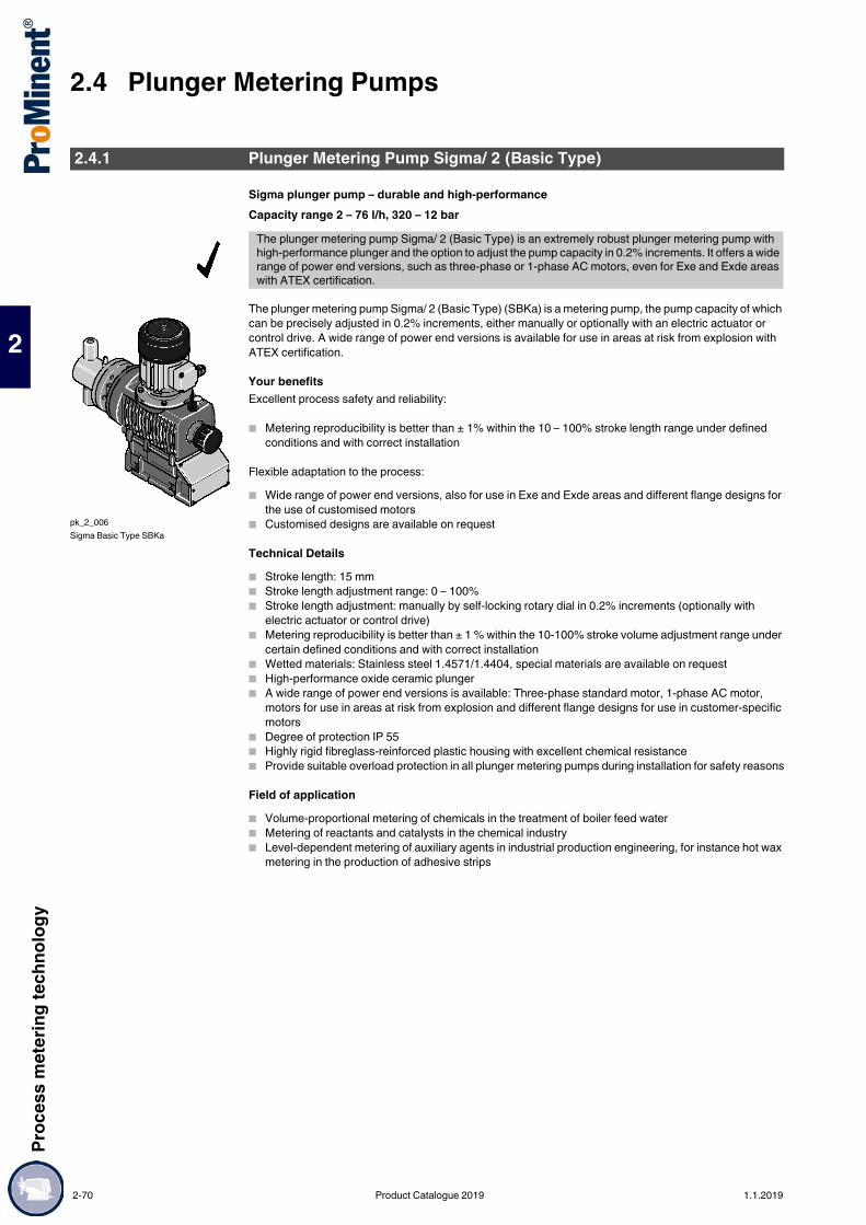
2.4 Plunger Metering PumpsPr
oces
s met
ering
tech
nolog
y
2
2.4Plunger Metering Pumps
Sigma plunger pump – durable and high-performanceCapacity range 2 – 76 l/h, 320 – 12 bar
The plunger metering pump Sigma/ 2 (Basic Type) (SBKa) is a metering pump, the pump capacity of which can be precisely adjusted in 0.2% increments, either manually or optionally with an electric actuator or control drive. A wide range of power end versions is available for use in areas at risk from explosion with ATEX certification.
Your benefitsExcellent process safety and reliability:
Metering reproducibility is better than ± 1% within the 10 – 100% stroke length range under defined conditions and with correct installation
Flexible adaptation to the process: Wide range of power end versions, also for use in Exe and Exde areas and different flange designs for
the use of customised motors Customised designs are available on request
Technical Details Stroke length: 15 mm Stroke length adjustment range: 0 – 100% Stroke length adjustment: manually by self-locking rotary dial in 0.2% increments (optionally with
electric actuator or control drive) Metering reproducibility is better than ± 1 % within the 10-100% stroke volume adjustment range under
certain defined conditions and with correct installation Wetted materials: Stainless steel 1.4571/1.4404, special materials are available on request High-performance oxide ceramic plunger A wide range of power end versions is available: Three-phase standard motor, 1-phase AC motor,
motors for use in areas at risk from explosion and different flange designs for use in customer-specific motors
Degree of protection IP 55 Highly rigid fibreglass-reinforced plastic housing with excellent chemical resistance Provide suitable overload protection in all plunger metering pumps during installation for safety reasons
Field of application Volume-proportional metering of chemicals in the treatment of boiler feed water Metering of reactants and catalysts in the chemical industry Level-dependent metering of auxiliary agents in industrial production engineering, for instance hot wax
metering in the production of adhesive strips
2.4.1 Plunger Metering Pump Sigma/ 2 (Basic Type)
The plunger metering pump Sigma/ 2 (Basic Type) is an extremely robust plunger metering pump with high-performance plunger and the option to adjust the pump capacity in 0.2% increments. It offers a wide range of power end versions, such as three-phase or 1-phase AC motors, even for Exe and Exde areas with ATEX certification.
pk_2_006Sigma Basic Type SBKa
2-70 Product Catalogue 2019 1.1.2019

Proc
ess m
eter
ing te
chno
logy
2.4 Plunger Metering Pumps
2
Sigma Basic Type Control FunctionsStroke length actuator/controllerActuator for automatic stroke length adjustment, actuating period approx. 1 sec for 1% stroke length, 1 kΩ response signal potentiometer, enclosure rating IP 54.Controller consists of actuator with servomotor and integrated servo control for stroke length adjustment via a standard signal. Standard signal input 0/4-20 mA corresponds to stroke length 0 - 100%. Automatic/manual operation selection key for manual stroke adjustment. Mechanical status display of actual stroke length value output 0/4-20 mA for remote display.
Variable speed motors with integrated speed controller (identity code specification V)Power supply 1 ph 230 V, 50/60 Hz, 0.37 kW.External control with 0/4-20 mA (see pk_2_103)(Speed Controllers see p. )
Speed controllers in metal housing (identity code specification Z) The speed controller assembly consists of a frequency converter and a variable speed motor of 0.37 kW.(Speed Controllers see p. )
pk_2_103Variable speed motor with integrated frequency converter
1.1.2019 Product Catalogue 2019 2-71

2.4 Plunger Metering PumpsPr
oces
s met
ering
tech
nolog
y
2
Technical Data
Materials in Contact With the Medium
Motor Data
The motors are designed in compliance with the Ecodesign Directive 2009/125/EC.
Information for use in areas at risk from explosionOnly use pumps with the appropriate labelling in line with the ATEX Directive 2014/34/EU in premises at risk from explosion. Ensure that the explosion group, category and degree of protection specified on the label corresponds to or is better than the conditions prevalent in the intended field of application.
Type SBKa
With 1500 rpm motor at 50 Hz With 1800 rpm motor at 60 Hz Suc-tion lift
Perm. pre-pressure
suctionside
Connector Suction/Discharge Side
Shippingweight
Plung-er Ø
Delivery rate atmax. back
pressure
Max.stroke
rate
Delivery rate at max.back pressure
Max.stroke
rate bar l/h ml/
strokeStrokes/
min psi l/h gph
(US)Strokes/
min m WC bar Rp-DN kg mm
32002 320 1.9 0.46 71 4,641 2.3 0.61 84 5.0 160 1/4 24 823004 230 4.0 0.52 129 3,336 4.8 1.27 154 5.0 115 1/4 24 810006 100 6.4 0.55 195 1,450 7.6 2.01 233 5.0 50 1/4 24 814006 140 6.1 1.42 71 2,031 7.1 1.88 84 4.0 70 1/4 24 1210011 100 11.0 1.43 129 1,450 13.1 3.46 153 4.0 50 1/4 24 1205016 50 16.7 1.43 195 725 20.0 5.28 233 4.0 25 1/4 24 1207012 70 12.4 2.90 71 1,015 14.8 3.91 85 4.0 35 1/4 24 1704522 45 22.5 2.91 129 653 26.7 7.05 153 4.0 22.5 1/4 24 1702534 25 34.1 2.92 195 363 40.8 10.78 233 4.0 12.5 1/4 24 1704022 40 22.4 5.26 71 580 26.5 7.00 84 4.0 20 3/8 25 2302541 25 41.5 5.37 129 363 49.2 13.00 153 4.0 12.5 3/8 25 2301264 12 64.0 5.45 195 174 76.0 20.08 233 4.0 6 3/8 25 23
Material Dosing head Suction/pressure connector Seals/ball seat Balls Ball seatSST Stainless steel 1.4404 Stainless steel 1.4404 PTFE or Ceramic Stainless steel 1.4404
PTFE +25% carbon
Identity code specification
Power supply Remarks
S 3-phase, IP 55 220 – 240 V/380 – 420 V250 – 280 V/440 – 480 V
50 Hz60 Hz
0.25 kW
R 3-phase, IP 55 230 V/400 V 50/60 Hz 0.37 kW with PTC, speed adjustment range 1:20 with external fan 1-phase 230 V; 50/60 Hz
V0 1-phase, IP 55 230 V ± 5 % 50/60 Hz 0.37 kW Variable speed motor with integrated frequency converter
M 1-phase AC, IP 55 230 V ± 5 % 50/60 Hz 0.18 kWN 1-phase AC, IP 55 115 V ± 5 % 60 Hz 0.18 kWL1 3-phase, II 2G Ex h IIC T3 Gb X 220 – 240 V/380 – 420 V 50 Hz 0.18 kWL2 3-phase, II 2G Ex h IIC T4 Gb X 220 – 240 V/380 – 420 V 50 Hz 0.18 kW with PTC, speed control range 1:5P1 3-phase, II 2G Ex h IIC T3 Gb X 250 – 280 V/440 – 480 V 60 Hz 0.18 kWP2 3-phase, II 2G Ex h IIC T4 Gb X 250 – 280 V/440 – 480 V 60 Hz 0.21 kW with PTC, speed control range 1:5
Motor data sheets can be requested for more information.Special motors or special motor flanges are available on request.
2-72 Product Catalogue 2019 1.1.2019

Proc
ess m
eter
ing te
chno
logy
2.4 Plunger Metering Pumps
2
Identity Code Ordering System for SBKa
Spare Parts KitsConsisting of: 1 ceramic metering plunger, 4 valve balls, 4 ball seat discs, 2 PTFE/graphite ball seals, 2 plunger guides, 14 flat seals, 2 O-rings.
SBKa Drive typeHK Main drive, plunger
Type bar l/h bar l/h bar l/h
32002 320 1.9 10011 100 11.0 02534 25 34.123004 230 4.0 05016 50 16.7 04022 40 22.410006 100 6.4 07012 70 12.4 02541 25 41.514006 140 6.1 04522 45 22.5 01264 12 64.0
Liquid end materialSS Stainless steel
Sealing material*T PTFE
Displacement body*4 Plunger (oxide ceramic)
Liquid end version0 No spring (standard)1 With 2 valve springs, Hastelloy C, 0.1 bar
Hydraulic connection0 Standard threaded connector (according to technical data)
Version0 With ProMinent® logo (standard)1 Without ProMinent® logoM Modified
Electrical power supplyS 3 ph, 230 V/400 V 50/60 Hz, 0.18 kWR 3 ph, variable speed motor, 230/400 V, 0.37 kWV (0) Variable speed motor with integrated SC 1 pH, 230 V, 50/60 HzZ 1 ph, variable speed set 230 V, 50/60 HzM 1 ph, AC, 230 V/ 50/60 Hz, 0.18 kWN 1 ph, AC 115 V 60 Hz, 0.18 kWL 3 ph, 230 V/400 V, 50 Hz, (EExe, EExd), 0.18 kWP 3 ph, 230 V/400 V, 60 Hz, (EExe, EExd), 0.18 kW1 No motor, with B 14 flange (size 71 (DIN)2 No motor, C 56 flange (NEMA)3 No motor, B 5 size 63 (DIN)
Enclosure rating0 IP 55 (standard)1 Exe motor version ATEX-T32 Exd motor version ATEX-T4A ATEX power end
Stroke sensor0 No stroke sensor (standard)2 Pacing relay (reed relay)3 Stroke sensor (Namur) for hazardous locations
Stroke length adjustment0 Manual (standard)1 With stroke positioning motor, 230 V/50/60 Hz2 With stroke positioning motor, 115 V/50/60 Hz3 With stroke control motor 0...20 mA 230 V/50/60 Hz4 With stroke control motor 4...20 mA 230 V/50/60 Hz5 With stroke control motor 0...20 mA 115 V/50/60 Hz6 With stroke control motor 4...20 mA 115 V/50/60 Hz
Type Order no.Liquid end FK 08 Applies to identity code: 32002, 23004, 10006 1001572Liquid end FK 12.5 Applies to identity code: 14006, 10011, 05016 910470Liquid end FK 25 Applies to identity code: 07012, 04522, 02534 910471Liquid end FK 50 Applies to identity code: 04022, 02541, 01264 910472
1.1.2019 Product Catalogue 2019 2-73

2.4 Plunger Metering PumpsPr
oces
s met
ering
tech
nolog
y
2
Sigma plunger pump – durable, high-performance and intelligent.Capacity range 2 – 76 l/h, 320 – 12 bar
The plunger metering pump Sigma/ 2 (Control Type) (SCKa) is a metering pump, the pump capacity of which can be precisely adjusted in 0.2% increments, either manually or optionally with an electric actuator or control drive. The integrated controller allows the pump to adapt quickly and reliably to changing metering tasks.
Your benefitsProcess reliability:
Metering reproducibility is better than ± 1% within the 10 – 100% stroke length range under defined conditions and with correct installation
Flexible adaptation to the process: The integrated controller allows the pump to adapt quickly and reliably to changing metering tasks Customised designs are available on request
Technical Details Stroke length: 15 mm Stroke length adjustment range: 0 – 100% Stroke length adjustment: manually by self-locking rotary dial in 0.2% increments (optionally with
electric actuator or control drive) Metering reproducibility is better than ± 1% within the 10-100% stroke length adjustment range under
certain defined conditions and with proper installation Wetted materials: Stainless steel 1,4571/1.4404, special materials are available on request High-performance oxide ceramic plunger Integrated control for analogue and/or contact operation Power supply: 1-phase, 100 – 230 V ±10%, 240 V ± 6%, 50/60 Hz (220 W) Degree of protection IP 55 Highly rigid fibreglass-reinforced plastic housing with excellent chemical resistance Provide suitable overload protection in all plunger metering pumps during installation for safety reasons
Field of application Volume-proportional metering of chemicals in the treatment of boiler feed water Metering of reactants and catalysts in the chemical industry Level-dependent metering of auxiliary agents in industrial production engineering, for instance hot wax
metering in the production of adhesive strips
2.4.2 Plunger Metering Pump Sigma/ 2 (Control Type)
The plunger metering pump Sigma/2 (Control Type) is an extremely robust metering pump with integral control for analogue and/or contact operation. It offers the option of adjusting the pump capacity in 0.2% increments. It offers a wide range of power end versions, and different flange designs.
P_ORL_066_SW1Sigma control type SCKa
pk_2_104Sigma Controller
2-74 Product Catalogue 2019 1.1.2019
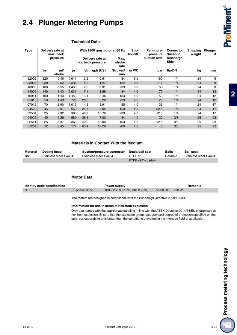
Proc
ess m
eter
ing te
chno
logy
2.4 Plunger Metering Pumps
2
Technical Data
Materials in Contact With the Medium
Motor Data
The motors are designed in compliance with the Ecodesign Directive 2009/125/EC.
Information for use in areas at risk from explosionOnly use pumps with the appropriate labelling in line with the ATEX Directive 2014/34/EU in premises at risk from explosion. Ensure that the explosion group, category and degree of protection specified on the label corresponds to or is better than the conditions prevalent in the intended field of application.
Type Delivery rate atmax. back
pressure
With 1800 rpm motor at 60 Hz Suc-tion lift
Perm. pre-pressure
suction side
Connector Suction/Discharge Side
Shippingweight
PlungerØ
Delivery rate atmax. back pressure
Max.stroke
rate bar ml/
stroke psi l/h gph (US) Strokes/
min m WC bar Rp-DN kg mm
32002 320 0.46 4,641 2.3 0.61 84 5.0 160 1/4 24 823004 230 0.52 3,336 4.8 1.27 154 5.0 115 1/4 24 810006 100 0.55 1,450 7.6 2.01 233 5.0 50 1/4 24 814006 140 1.42 2,031 7.1 1.88 84 4.0 70 1/4 24 1210011 100 1.43 1,450 13.1 3.46 153 4.0 50 1/4 24 1205016 50 1.43 725 20.0 5.28 233 4.0 25 1/4 24 1207012 70 2.90 1,015 14.8 3.91 85 4.0 35 1/4 24 1704522 45 2.91 653 26.7 7.05 153 4.0 22.5 1/4 24 1702534 25 2.92 363 40.8 10.78 233 4.0 12.5 1/4 24 1704022 40 5.26 580 26.5 7.00 84 4.0 20 3/8 25 2302541 25 5.37 363 49.2 13.00 153 4.0 12.5 3/8 25 2301264 12 5.45 174 65.4 17.28 200 4.0 6 3/8 25 23
Material Dosing head Suction/pressure connector Seals/ball seat Balls Ball seatSST Stainless steel 1.4404 Stainless steel 1.4404 PTFE or Ceramic Stainless steel 1.4404
PTFE +25% carbon
Identity code specification Power supply RemarksU 1-phase, IP 55 100 – 230 V ±10%, 240 V ±6%, 50/60 Hz 220 W
1.1.2019 Product Catalogue 2019 2-75

2.4 Plunger Metering PumpsPr
oces
s met
ering
tech
nolog
y
2
Identity Code Ordering System for SCKa
Spare Parts KitsConsisting of: 1 ceramic metering plunger, 4 valve balls, 4 ball seat discs, 2 PTFE/graphite ball seals, 2 plunger guides, 14 flat seals, 2 O-rings.
SCKa Drive typeHK Main drive, plunger
Type bar l/h bar l/h bar l/h
32002 320 2.3 10011 100 13.1 02534 25 34.123004 230 4.8 05016 50 16.7 04022 40 26.510006 100 6.4 07012 70 14.8 02541 25 49.214006 140 7.1 04522 45 26.7 01264 12 64.0
Liquid end materialSS Stainless steel
Sealing material*T PTFE
Displacement body*4 Plunger (oxide ceramic)
Liquid end version0 No spring (standard)1 With 2 valve springs, Hastelloy C 4, 0.1 bar
Hydraulic connection0 Standard threaded connector (according to technical data)
Version0 With ProMinent® logo1 Without ProMinent® logo
Electrical power supplyU 1 ph 100-230 V ±10%, 50/60 Hz
Cable and plugA 2 m EuropeanB 2 m SwissC 2 m AustralianD 2 m USA
Relay0 No relay1 With fault indicating relay 1x changeover 230 V – 2A3 With fault indicating relay 1x changeover 230 V – 2A4 As 1 + pacing relay 2x normally open 24 V - 100 mA5 As 3 with pacing relay 2x normally open 24 V – 100 mAA Shut-off and warning relays normally closed 2x normally open
24 V - 100 mAF Power relay normally closed 1x changeover 230 V - 8 A
Control variant0 Manual + external with pulse control1 Manual + external + pulse control + analogue
Access code0 No access code1 With access code
Metering monitor0 Input with pulse evaluation1 Input with cont. evaluation
Stroke length adjustment0 Manual
Type Order no.Liquid end FK 08 Applies to identity code: 32002, 23004, 10006 1001572Liquid end FK 12.5 Applies to identity code: 14006, 10011, 05016 910470Liquid end FK 25 Applies to identity code: 07012, 04522, 02534 910471Liquid end FK 50 Applies to identity code: 04022, 02541, 01264 910472
2-76 Product Catalogue 2019 1.1.2019

Proc
ess m
eter
ing te
chno
logy
2.4 Plunger Metering Pumps
2
Meta plunger pump – durable and high-performance Capacity range 6 – 59 l/h, 216 – 52 bar
The Meta (MTKa) is a plunger metering pump, the pump capacity of which can be precisely adjusted in 0.2% increments, either manually or optionally with an electric actuator or control drive. A wide range of power end versions is available for use in areas at risk from explosion with ATEX certification.
Your benefitsExcellent process safety and reliability:
Metering reproducibility is better than ± 0.5 % within the 10 – 100% stroke length range under defined conditions and with correct installation
Flexible adaptation to the process: Wide range of power end versions, also for use in Exe and Exde areas and different flange designs for
the use of customised motors Customised designs are available on request
Technical Details Stroke length: 15 mm, Stroke length adjustment range: 0 – 100% Stroke length adjustment: manually by self-locking rotary dial in 0.2% increments (optionally with
electric actuator or control drive) Metering reproducibility is better than ± 1% within the 10-100% stroke length adjustment range under
certain defined conditions and with proper installation Wetted materials: Stainless steel 1.4571/1.4404 High-performance oxide ceramic plunger A wide range of power end versions is available: Three-phase standard motor, 1-phase AC motor,
motors for use in areas at risk from explosion and different flange designs for use in customer-specific motors
Degree of protection IP 55 Fibreglass-reinforced plastic housing Provide suitable overload protection in all plunger metering pumps during installation for safety reasons.
Field of application Volume-proportional metering of chemicals in the treatment of boiler feed water Metering of reactants and catalysts in the chemical industry Level-dependent metering of auxiliary agents in industrial production engineering, for instance hot wax
metering in the production of adhesive strips
Control of Meta Piston Metering Pumps(Speed Controllers see p. )
Speed controllers in metal housing (Identity code characteristic Z)Frequency changer built into IP 54 protective housing and main switch designed for max. 0.37 kW motor output.Externally controlled with 0/4-20 mA / 0-10 V to correspond to 0-50 (60) Hz output frequency.Integrated controller with versatile functions e.g. switching between external/internal control. With internal control, frequency input is via arrow keys. Multi lingual fault message display and motor temperature monitoring (thermistor-protection).The speed controller assembly consists of a speed controller and a variable speed motor (see also identity code characteristic R).
2.4.3 Plunger Metering Pump Meta
The extremely high-performance Meta is a plunger metering pump with the option of adjusting the pump capacity in 0.2% increments. It offers a wide range of power end versions, such as three-phase or 1-phase AC motors, even for Exe and Exde areas with ATEX certification.
pk_2_010Meta plunger metering pump MTKa
pk_2_011Meta plunger metering pump MTKa
1.1.2019 Product Catalogue 2019 2-77
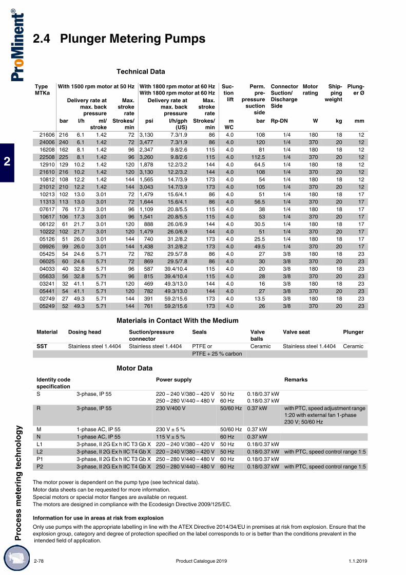
2.4 Plunger Metering PumpsPr
oces
s met
ering
tech
nolog
y
2
Technical Data
Materials in Contact With the Medium
Motor Data
The motors are designed in compliance with the Ecodesign Directive 2009/125/EC.
Information for use in areas at risk from explosionOnly use pumps with the appropriate labelling in line with the ATEX Directive 2014/34/EU in premises at risk from explosion. Ensure that the explosion group, category and degree of protection specified on the label corresponds to or is better than the conditions prevalent in the intended field of application.
Type MTKa
With 1500 rpm motor at 50 Hz With 1800 rpm motor at 60 HzWith 1800 rpm motor at 60 Hz
Suc-tion
lift
Perm.pre-
pressuresuction
side
Connector Suction/Discharge Side
Motorrating
Ship-ping
weight
Plung-er Ø
Delivery rate atmax. back
pressure
Max.stroke
rate
Delivery rate atmax. back
pressure
Max.stroke
rate bar l/h ml/
strokeStrokes/
min psi l/h/gph
(US)Strokes/
min m
WC bar Rp-DN W kg mm
21606 216 6.1 1.42 72 3,130 7.3/1.9 86 4.0 108 1/4 180 18 1224006 240 6.1 1.42 72 3,477 7.3/1.9 86 4.0 120 1/4 370 20 1216208 162 8.1 1.42 96 2,347 9.8/2.6 115 4.0 81 1/4 180 18 1222508 225 8.1 1.42 96 3,260 9.8/2.6 115 4.0 112.5 1/4 370 20 1212910 129 10.2 1.42 120 1,878 12.2/3.2 144 4.0 64.5 1/4 180 18 1221610 216 10.2 1.42 120 3,130 12.2/3.2 144 4.0 108 1/4 370 20 1210812 108 12.2 1.42 144 1,565 14.7/3.9 173 4.0 54 1/4 180 18 1221012 210 12.2 1.42 144 3,043 14.7/3.9 173 4.0 105 1/4 370 20 1210213 102 13.0 3.01 72 1,479 15.6/4.1 86 4.0 51 1/4 180 18 1711313 113 13.0 3.01 72 1,644 15.6/4.1 86 4.0 56.5 1/4 370 20 1707617 76 17.3 3.01 96 1,109 20.8/5.5 115 4.0 38 1/4 180 18 1710617 106 17.3 3.01 96 1,541 20.8/5.5 115 4.0 53 1/4 370 20 1706122 61 21.7 3.01 120 888 26.0/6.9 144 4.0 30.5 1/4 180 18 1710222 102 21.7 3.01 120 1,479 26.0/6.9 144 4.0 51 1/4 370 20 1705126 51 26.0 3.01 144 740 31.2/8.2 173 4.0 25.5 1/4 180 18 1709926 99 26.0 3.01 144 1,438 31.2/8.2 173 4.0 49.5 1/4 370 20 1705425 54 24.6 5.71 72 782 29.5/7.8 86 4.0 27 3/8 180 18 2306025 60 24.6 5.71 72 869 29.5/7.8 86 4.0 30 3/8 370 20 2304033 40 32.8 5.71 96 587 39.4/10.4 115 4.0 20 3/8 180 18 2305633 56 32.8 5.71 96 815 39.4/10.4 115 4.0 28 3/8 370 20 2303241 32 41.1 5.71 120 469 49.3/13.0 144 4.0 16 3/8 180 18 2305441 54 41.1 5.71 120 782 49.3/13.0 144 4.0 27 3/8 370 20 2302749 27 49.3 5.71 144 391 59.2/15.6 173 4.0 13.5 3/8 180 18 2305249 52 49.3 5.71 144 761 59.2/15.6 173 4.0 26 3/8 370 20 23
Material Dosing head Suction/pressure connector
Seals Valve balls
Valve seat Plunger
SST Stainless steel 1.4404 Stainless steel 1.4404 PTFE or Ceramic Stainless steel 1.4404 CeramicPTFE + 25 % carbon
Identity code specification
Power supply Remarks
S 3-phase, IP 55 220 – 240 V/380 – 420 V250 – 280 V/440 – 480 V
50 Hz60 Hz
0.18/0.37 kW0.18/0.37 kW
R 3-phase, IP 55 230 V/400 V 50/60 Hz 0.37 kW with PTC, speed adjustment range 1:20 with external fan 1-phase 230 V; 50/60 Hz
M 1-phase AC, IP 55 230 V ± 5 % 50/60 Hz 0.37 kWN 1-phase AC, IP 55 115 V ± 5 % 60 Hz 0.37 kWL1 3-phase, II 2G Ex h IIC T3 Gb X 220 – 240 V/380 – 420 V 50 Hz 0.18/0.37 kWL2 3-phase, II 2G Ex h IIC T4 Gb X 220 – 240 V/380 – 420 V 50 Hz 0.18/0.37 kW with PTC, speed control range 1:5P1 3-phase, II 2G Ex h IIC T3 Gb X 250 – 280 V/440 – 480 V 60 Hz 0.18/0.37 kWP2 3-phase, II 2G Ex h IIC T4 Gb X 250 – 280 V/440 – 480 V 60 Hz 0.18/0.37 kW with PTC, speed control range 1:5
The motor power is dependent on the pump type (see technical data).Motor data sheets can be requested for more information.Special motors or special motor flanges are available on request.
2-78 Product Catalogue 2019 1.1.2019

Proc
ess m
eter
ing te
chno
logy
2.4 Plunger Metering Pumps
2
Identity Code Ordering System for MTKaMTKa Drive type
H Main driveA Add-on drive
Type bar l/h bar l/h bar l/h bar l/h
21606 216 6.1 10812 108 12.2 06122 61 21.7 04033 40 32.824006 240 6.1 21012 210 12.2 10222 102 21.7 05633 56 32.816208 162 8.1 10213 102 13.0 05126 51 26.0 03241 32 41.122508 225 8.1 11313 113 13.0 09926 99 26.0 05441 54 41.112910 129 10.2 07617 76 17.3 05425 54 24.6 02749 27 49.321610 216 10.2 10617 106 17.3 06025 60 24.6 05249 52 49.3
Liquid end materialSS Stainless steel
Sealing material*T PTFE
Displacement body*S Standard plunger, oxide ceramic
Liquid end version0 No valve springs1 With 2 valve springs, Hastelloy C, 0.1 bar
Hydraulic connection0 Standard threaded connector (according to technical data)
Version0 With ProMinent® logo (standard)1 Without ProMinent® logoM Modified
Electrical power supplyS 3 ph, 230 V/400 V, 50/60 Hz (WBS)R 3 ph, variable speed motor, 230 V/400 VZ 1 ph, variable speed set 230 V, 50/60 HzM 1 ph, AC, 230 V, 50/60 HzN 1 ph, AC, 115 V, 60 HzL 3 ph, 230 V/400 V, 50 Hz, (Exe, Exd)P 3 ph, 230 V/400 V, 60 Hz, (Exe, Exd)1 No motor, with flange 90/632 No motor, with flange 140/713 No motor, with flange 160/714 No motor, with flange 56 C0 Add-on pump (no motor)
Enclosure rating0 IP 55 (standard)1 Exe motor version ATEX-T32 Exd motor version ATEX-T4A ATEX power end
Stroke sensor0 No stroke sensor (standard)1 With stroke sensor, Namur signal (Ex)
Stroke length adjustment0 Manual (standard)2 With stroke positioning, 115 V/50/60 HzA With stroke control motor 0...20 mA 230 V/50/60 HzB With stroke control motor 4...20 mA 230 V/50/60 HzC With stroke control motor 0...20 mA 115 V/50/60 HzD With stroke control motor 4...20 mA 115 V/50/60 Hz
1.1.2019 Product Catalogue 2019 2-79

2.4 Plunger Metering PumpsPr
oces
s met
ering
tech
nolog
y
2
Spare Parts Kits for Plunger Metering Pump Meta (MTKa)Consisting of:
Mounting Frame for Meta MTMa and MTKaA base frame is available for main and add-on pump combinations.
1 ceramic plunger4 valve balls4 ball seat discs2 PTFE /graphite plunger packing rings2 plunger guide bands14 flat seals2 O-rings
Order no.Liquid end FK 12.5 Applies to identity code: 21606, 24006, 16208, 22508, 12910, 21610, 10812, 21012
910470
Liquid end FK 25 applies to identity code: 10213, 11313, 07617, 10617, 06122, 10222, 05126, 09926
910471
Liquid end FK 50 applies to identity code: 05425, 06025, 04033, 05633, 03241, 05441, 02749, 05249
910472
Order no.Base frame for main and one add-on pump 803897Base frame for main and two add-on pumps 803898Base frame for main and three add-on pumps 803899
2-80 Product Catalogue 2019 1.1.2019

Proc
ess m
eter
ing te
chno
logy
2.4 Plunger Metering Pumps
2
Powerful, built to last with a plungerCapacity range of single head pump: 8 – 1,141 l/h, 320 – 11 bar
The plunger metering pump Makro TZ (TZKa) has an adjustable eccentric drive mechanism and, together with the Makro TZ diaphragm metering pump, forms a range of drive mechanisms with stroke lengths of 10 and/or 20 mm. This covers the capacity range from 8 to 2,100 l/h at 320 – 4 bar. A wide range of drive versions is available, including some for use in Exe and Exde areas with ATEX certification.
Your benefitsProcess reliability:
Metering reproducibility is better than ± 0.5 % within the 10 – 100% stroke length range under defined conditions and with correct installation
Excellent flexibility: The modular construction with single and double head versions permits a wide range of applications,
with the double head designs being operated in push-pull mode It is possible to combine up to 4 metering units, even with different pump capacities, in multiple pump
systems 4 different gear ratios are available Customised designs are available on request
Technical Details Stroke length: 0-20 mm, Rod force: 8,000 N Stroke length adjustment range: 0 – 100% Stroke length adjustment: manually by means of shift ring in 0.5% increments (optionally with electric
actuator or control drive) Metering reproducibility is better than ± 0.5% within the 10 – 100% stroke length range under defined
conditions and with proper installation. Observe the information in the operating instructions. High-performance ceramic-coated stainless steel plunger Wetted materials: Stainless steel 1.4571.
Special materials are available on request A wide range of power end versions is available: Three-phase standard motors, motors for use in areas
at risk from explosion and different flange designs for use in customer-specific motors Degree of protection: IP 55 Salt water-resistant, acrylic resin-coated cast aluminium housing Provide suitable overload protection in all plunger metering pumps during installation for safety reasons
Field of application Volume-proportional metering of chemicals/additives in water treatment Metering of reactants and catalysts in the chemical industry Level-dependent metering of additives in industrial production engineering
2.4.4 Plunger Metering Pump Makro TZ
The plunger metering pump Makro TZ impresses with its excellent process reliability, outstanding flexibility and its modular construction enables it to be outstandingly adapted to the performance requirements of the respective application.
pk_2_019Makro TZ plunger metering pump
pk_2_018Makro TZ TZKa externally mounted pump
pk_2_020Makro TZ TZKa double head pump
1.1.2019 Product Catalogue 2019 2-81
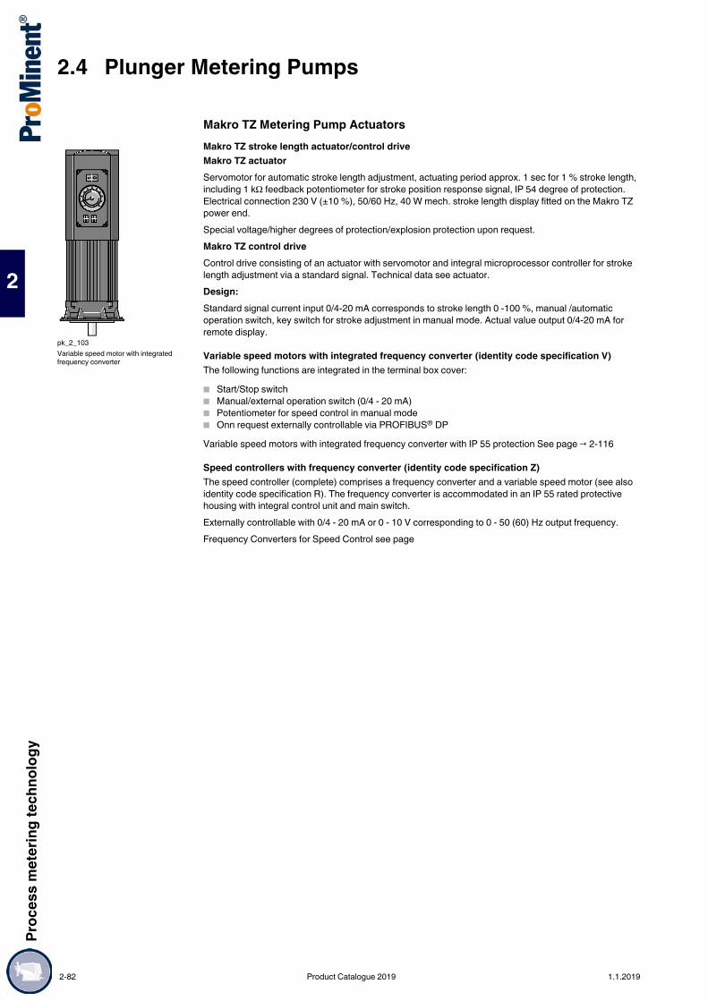
2.4 Plunger Metering PumpsPr
oces
s met
ering
tech
nolog
y
2
Makro TZ Metering Pump ActuatorsMakro TZ stroke length actuator/control driveMakro TZ actuatorServomotor for automatic stroke length adjustment, actuating period approx. 1 sec for 1 % stroke length, including 1 kΩ feedback potentiometer for stroke position response signal, IP 54 degree of protection. Electrical connection 230 V (±10 %), 50/60 Hz, 40 W mech. stroke length display fitted on the Makro TZ power end.Special voltage/higher degrees of protection/explosion protection upon request.Makro TZ control driveControl drive consisting of an actuator with servomotor and integral microprocessor controller for stroke length adjustment via a standard signal. Technical data see actuator.Design:Standard signal current input 0/4-20 mA corresponds to stroke length 0 -100 %, manual /automatic operation switch, key switch for stroke adjustment in manual mode. Actual value output 0/4-20 mA for remote display.
Variable speed motors with integrated frequency converter (identity code specification V)The following functions are integrated in the terminal box cover: Start/Stop switch Manual/external operation switch (0/4 - 20 mA) Potentiometer for speed control in manual mode Onn request externally controllable via PROFIBUS® DPVariable speed motors with integrated frequency converter with IP 55 protection See page → 2-116
Speed controllers with frequency converter (identity code specification Z)The speed controller (complete) comprises a frequency converter and a variable speed motor (see also identity code specification R). The frequency converter is accommodated in an IP 55 rated protective housing with integral control unit and main switch.Externally controllable with 0/4 - 20 mA or 0 - 10 V corresponding to 0 - 50 (60) Hz output frequency.Frequency Converters for Speed Control see page
pk_2_103Variable speed motor with integrated frequency converter
2-82 Product Catalogue 2019 1.1.2019

Proc
ess m
eter
ing te
chno
logy
2.4 Plunger Metering Pumps
2
Technical Data
Other gear reduction ratios are available upon request.The permissible admission pressure on the suction side is approx. 50% of the max. permissible back pressure.** The suction and discharge connectors Rp 1/4 and Rp 3/8 are inner threaded and fitted with double ball valves.
Materials in Contact With the Medium
Type TZKa
With 1500 rpm motor at 50 Hz With 1800 rpm motor at 60 Hz Suc-tion lift
Connection, suction/discharge side
Shippingweight
PlungerØ
Delivery rate atmax. back pressure
Max.stroke
rate
Delivery rate atmax. back pressure
Max.stroke rate
bar l/h ml/stroke
Strokes/min
psi l/h/gph (US) Strokes/min
m WC G–DN kg mm
320009 320 8.7 2.0 72 4,627 10/2.6 86 4.0 Rp 1/4**–8 50 12320012 320 11.6 2.0 96 4,627 14/3.7 115 4.0 Rp 1/4**–8 50 12320014 320 14.5 2.0 120 4,627 17/4.5 144 4.0 Rp 1/4**–8 50 12320017 320 17.4 2.0 144 4,627 21/5.5 173 4.0 Rp 1/4**–8 50 12320018 320 17.7 4.1 72 4,627 21/5.5 86 4.0 Rp 1/4**–8 50 17320024 320 23.6 4.1 96 4,627 28/7.4 115 4.0 Rp 1/4**–8 54 17320030 320 29.5 4.1 120 4,627 35/9.2 144 4.0 Rp 1/4**–8 54 17313035 313 35.4 4.1 144 4,526 42/11.1 173 4.0 Rp 1/4**–8 54 17192033 192 32.9 7.6 72 2,776 39/10.3 86 4.0 Rp 3/8**–10 55 23192044 192 43.9 7.6 96 2,776 59/15.6 115 4.0 Rp 3/8**–10 55 23192055 192 54.8 7.6 120 2,776 66/17.4 144 4.0 Rp 3/8**–10 55 23168066 168 65.8 7.6 144 2,437 79/20.9 173 4.0 Rp 3/8**–10 55 23113057 113 57.5 13.3 72 1,634 69/18.2 86 4.0 Rp 3/8**–10 56 30113077 113 76.6 13.3 96 1,634 92/24.3 115 4.0 Rp 3/8**–10 56 30113096 113 95.8 13.3 120 1,634 115/30.4 144 4.0 Rp 3/8**–10 56 30096115 96 114.9 13.3 144 1,392 138/36.5 173 4.0 Rp 3/8**–10 56 30063104 63 104.3 24.2 72 911 125/33.0 86 4.0 G 1 1/4–20 58 40063139 63 139.0 24.2 96 911 167/44.1 115 4.0 G 1 1/4–20 58 40063174 63 173.8 24.2 120 914 209/55.2 144 4.0 G 1 1/4–20 58 40052208 52 208.5 24.2 144 754 250/66.0 173 4.0 G 1 1/4–20 58 40040163 40 162.9 37.7 72 578 195/51.5 86 4.0 G 1 1/4–20 58 50040217 40 217.2 37.7 96 578 261/68.9 115 4.0 G 1 1/4–20 58 50040271 40 271.5 37.7 120 580 326/86.1 144 4.0 G 1 1/4–20 58 50033326 33 325.8 37.7 144 479 391/103.3 173 4.0 G 1 1/4–20 58 50028237 28 237.0 54.9 72 405 284/75.0 86 4.0 G 1 1/2–25 62 60028316 28 315.9 54.9 96 405 379/100.1 115 4.0 G 1 1/2–25 62 60027395 27 394.9 54.9 120 392 474/125.2 144 4.0 G 1 1/2–25 62 60022474 22 473.9 54.9 144 319 569/150.3 173 4.0 G 1 1/2–25 62 60020322 20 322.5 74.7 72 289 387/102.2 86 4.0 G 1 1/2–25 62 70020430 20 430.0 74.7 96 289 516/136.3 115 4.0 G 1 1/2–25 62 70020538 20 537.6 74.7 120 290 645/170.4 144 4.0 G 1 1/2–25 62 70016645 16 645.1 74.7 144 232 774/204.5 173 4.0 G 1 1/2–25 62 70014475 14 475.1 110.0 72 202 571/150.8 86 4.0 G 2 1/4–40 68 85014634 14 634.1 110.0 96 202 761/201.0 115 4.0 G 2 1/4–40 68 85013793 13 792.6 110.0 120 189 951/251.2 144 4.0 G 2 1/4–40 68 85011951 11 951.1 110.0 144 160 1,141/301.4 173 4.0 G 2 1/4–40 68 85
Pump type
Hydraulic Ø mm Dosing head connection Suction/pressure seals
Ball seat Valve balls Plunger
SST …12 S to 50 S Stainless steel 1.4571/1.4404 1.4571/1.4404 SS/PTFE Oxide ceramic Stainless steel/ceramic
SST …60 S to 70 S Stainless steel 1.4571/1.4404 1.4581 PTFE/PTFE Stainless steel 1.4404
Stainless steel/ceramic
SST …85 S Stainless steel 1.4571/1.4404 1.4581 PTFE/PTFE 1.4404 (plate) Hast. C (spring)
Stainless steel/ceramic
1.1.2019 Product Catalogue 2019 2-83

2.4 Plunger Metering PumpsPr
oces
s met
ering
tech
nolog
y
2
Identity Code Ordering System TZKa
* Digits 1 - 3=back pressure [bar]; digits 4 - 6=feed rate [l/h]
TZKa Drive typeH Main driveA Add-onD Double main driveB Double add-on
Type*320009 320030 113057 063174 028237 020538320012 313035 113077 052208 028316 016645320014 192033 113096 040163 027395 014475320017 192044 096115 040217 022474 014634320018 192055 063104 040271 020322 013793320024 168066 063139 033326 020430 011951
Liquid end materialSS Stainless steel
Sealing materialT PTFE
Displacement bodyS Stainless steel plunger, chromium dioxide-coated
Liquid end version0 No valve springs1 With valve springs
Hydraulic connection0 Standard connection4 SS union nut and insert
Version0 With ProMinent® logo, no frame2 Without ProMinent® logo, no frameA With ProMinent® logo, with frame, simplexB With ProMinent® logo, with frame, duplexC With ProMinent® logo, with frame, triplexM Modified
Electrical power supplyS 3 ph. 230/400 V 50/60 Hz (WBS)R Variable speed motor 4-pole 230/400 VV (0) Variable speed motor with integr. frequency converterZ 1 ph, variable speed control set 1 ph, 230 V, 50/60 HzP 3 ph. 230/400 V 60 Hz (Exe, Exd)L 3 ph. 230/400 V 50 Hz (Exe, Exd)V (2) With integrated frequency converter (Exd)4 No motor, with 56 C flange7 No motor, with 120/80 flange8 No motor, with 160/90 flange0 Without motor, externally mounted drive
Enclosure rating0 IP 55 (Standard) ISO class F1 Exe version ATEX-T32 Exd version ATEX-T4A ATEX power end
Stroke sensor0 No stroke sensor1 With stroke sensor (Namur)
Stroke length adjustment0 Stroke length adjustment, man.1 230 V stroke adjustment motor2 115 V stroke adjustment motor3 230 V 0-20 mA stroke controller4 230 V 4-20 mA stroke controller5 115 V 0-20 mA stroke controller6 115 V 4-20 mA stroke controller
Application0 Standard
2-84 Product Catalogue 2019 1.1.2019
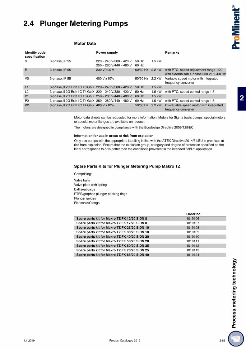
Proc
ess m
eter
ing te
chno
logy
2.4 Plunger Metering Pumps
2
Motor Data
Motor data sheets can be requested for more information. Motors for Sigma basic pumps, special motors or special motor flanges are available on request.The motors are designed in compliance with the Ecodesign Directive 2009/125/EC.
Information for use in areas at risk from explosionOnly use pumps with the appropriate labelling in line with the ATEX Directive 2014/34/EU in premises at risk from explosion. Ensure that the explosion group, category and degree of protection specified on the label corresponds to or is better than the conditions prevalent in the intended field of application.
Spare Parts Kits for Plunger Metering Pump Makro TZComprising:
Identity code specification
Power supply Remarks
S 3-phase, IP 55 220 – 240 V/380 – 420 V250 – 280 V/440 – 480 V
50 Hz60 Hz
1.5 kW
R 3-phase, IP 55 230 V/400 V 50/60 Hz 2.2 kW with PTC, speed adjustment range 1:20 with external fan 1-phase 230 V; 50/60 Hz
V0 3-phase, IP 55 400 V ±10% 50/60 Hz 2.2 kW Variable speed motor with integrated frequency converter
L1 3-phase, II 2G Ex h IIC T3 Gb X 220 – 240 V/380 – 420 V 50 Hz 1.5 kWL2 3-phase, II 2G Ex h IIC T4 Gb X 220 – 240 V/380 – 420 V 50 Hz 1.5 kW with PTC, speed control range 1:5P1 3-phase, II 2G Ex h IIC T3 Gb X 250 – 280 V/440 – 480 V 60 Hz 1.5 kWP2 3-phase, II 2G Ex h IIC T4 Gb X 250 – 280 V/440 – 480 V 60 Hz 1.5 kW with PTC, speed control range 1:5V2 3-phase, II 2G Ex h IIC T4 Gb X 400 V ±10% 50/60 Hz 2.2 kW Ex-variable speed motor with integrated
frequency converter
Valve ballsValve plate with springBall seat discsPTFE/graphite plunger packing ringsPlunger guidesFlat seals/O rings
Order no.Spare parts kit for Makro TZ FK 12/20 S DN 8 1019106Spare parts kit for Makro TZ FK 17/20 S DN 8 1019107Spare parts kit for Makro TZ FK 23/20 S DN 10 1019108Spare parts kit for Makro TZ FK 30/20 S DN 10 1019109Spare parts kit for Makro TZ FK 40/20 S DN 20 1019110Spare parts kit for Makro TZ FK 50/20 S DN 20 1019111Spare parts kit for Makro TZ FK 60/20 S DN 25 1019112Spare parts kit for Makro TZ FK 70/20 S DN 25 1019113Spare parts kit for Makro TZ FK 85/20 S DN 40 1019124
1.1.2019 Product Catalogue 2019 2-85
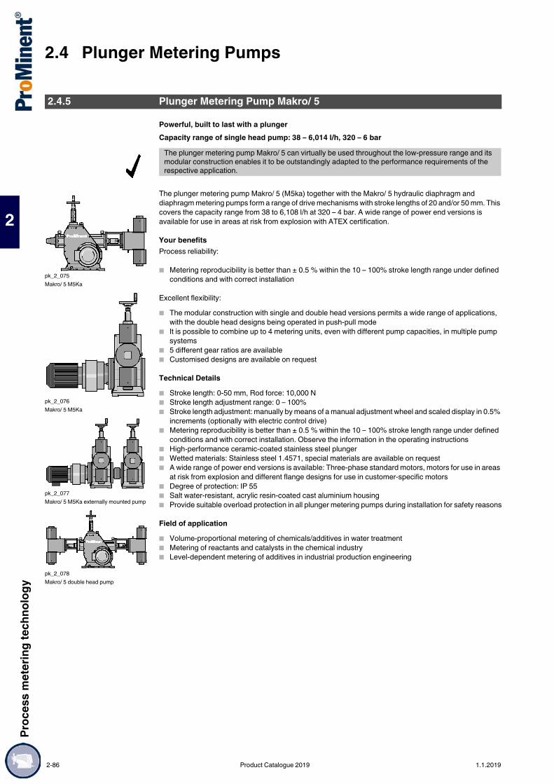
2.4 Plunger Metering PumpsPr
oces
s met
ering
tech
nolog
y
2
Powerful, built to last with a plungerCapacity range of single head pump: 38 – 6,014 l/h, 320 – 6 bar
The plunger metering pump Makro/ 5 (M5ka) together with the Makro/ 5 hydraulic diaphragm and diaphragm metering pumps form a range of drive mechanisms with stroke lengths of 20 and/or 50 mm. This covers the capacity range from 38 to 6,108 l/h at 320 – 4 bar. A wide range of power end versions is available for use in areas at risk from explosion with ATEX certification.
Your benefitsProcess reliability:
Metering reproducibility is better than ± 0.5 % within the 10 – 100% stroke length range under defined conditions and with correct installation
Excellent flexibility: The modular construction with single and double head versions permits a wide range of applications,
with the double head designs being operated in push-pull mode It is possible to combine up to 4 metering units, even with different pump capacities, in multiple pump
systems 5 different gear ratios are available Customised designs are available on request
Technical Details Stroke length: 0-50 mm, Rod force: 10,000 N Stroke length adjustment range: 0 – 100% Stroke length adjustment: manually by means of a manual adjustment wheel and scaled display in 0.5%
increments (optionally with electric control drive) Metering reproducibility is better than ± 0.5 % within the 10 – 100% stroke length range under defined
conditions and with correct installation. Observe the information in the operating instructions High-performance ceramic-coated stainless steel plunger Wetted materials: Stainless steel 1.4571, special materials are available on request A wide range of power end versions is available: Three-phase standard motors, motors for use in areas
at risk from explosion and different flange designs for use in customer-specific motors Degree of protection: IP 55 Salt water-resistant, acrylic resin-coated cast aluminium housing Provide suitable overload protection in all plunger metering pumps during installation for safety reasons
Field of application Volume-proportional metering of chemicals/additives in water treatment Metering of reactants and catalysts in the chemical industry Level-dependent metering of additives in industrial production engineering
2.4.5 Plunger Metering Pump Makro/ 5
The plunger metering pump Makro/ 5 can virtually be used throughout the low-pressure range and its modular construction enables it to be outstandingly adapted to the performance requirements of the respective application.
pk_2_075Makro/ 5 M5Ka
pk_2_076Makro/ 5 M5Ka
pk_2_077Makro/ 5 M5Ka externally mounted pump
pk_2_078Makro/ 5 double head pump
2-86 Product Catalogue 2019 1.1.2019

Proc
ess m
eter
ing te
chno
logy
2.4 Plunger Metering Pumps
2
Makro/ 5 Pump ControlStroke length variable speed drive Makro/ 5Variable speed drive consisting of actuator with motor actuator and integrated microprocessor controller for stroke length adjustment via a standard signal. Actuating time approx. 100 sec. for 100% stroke length, equipped with 2 limit switches for min./max. position, IP rating: IP 52. Electrical connection 230 V (±10%), 50/60 Hz, approx. 40 W, mech. stroke position indicator present at drive Makro/ 5.Special voltage/higher IP ratings/Ex protection on request.Includes:Standard current input 0/4-20 mA (corresponds to stroke length 0-100%); internal switch for manual/automatic operation, key switch for stroke adjustment in manual operation mode. Actual value output 0/4-20 mA for remote display.
Frequency converter for speed control in metal housing, IP rating 54Frequency converter installed in protective housing IP 54 with integrated control unit and main switch suitable for the motor output stated in the following.Externally controllable with 0/4-20 mA or 0-10V corresponding to 0-50 (60) Hz output frequency.Integrated control unit with numerous functions, such as toggling external/internal control. With internal control, frequency setting is via arrow keys, error message on multi lingual display etc.Including evaluator for temperature monitoring of the motor (thermistor protection).
Stroke sensor with namur signalMounted on the crank drive of the Makro/5 gearbox. For precise detection of each metering stroke, consisting of actuating cams and inductive proximity switch, switching signal according to Namur. Combined with electronic preselection counters suitable for batch metering or proportional metering in connection with the proportional control.Retrofitting is only possible on factory premises.Approved for ex-proof operation with IP rating EEx ia II C T6.
1.1.2019 Product Catalogue 2019 2-87

2.4 Plunger Metering PumpsPr
oces
s met
ering
tech
nolog
y
2
Technical DataType M5Ka
With 1500 rpm motor at 50 Hz With 1800 rpm motor at 60 Hz Suc-tion
lift
Connection, suction/discharge side
Shippingweight
PlungerØ
Delivery rate atmax. back pressure
Max.stroke
rate
Delivery rate atmax. back pressure
Max.stroke
rate bar l/h ml/
strokeStrokes/
min psi l/h gph (US) Strokes/
min m WC G–DN kg mm
3200038 320 38 11 60 4,640 44 12 71 3.0 Rp 1/4–8 300 173200048 320 48 11 75 4,640 56 15 89 3.0 Rp 1/4–8 300 173200066 320 66 11 103 4,640 78 21 123 3.0 Rp 1/4–8 300 173200085 320 85 11 133 4,640 101 27 159 3.0 Rp 3/8–10 300 173200100 320 100 11 156 – – – – 3.0 Rp 3/8–10 300 172400070 240 70 21 60 3,480 82 22 71 3.0 Rp 3/8–10 300 232400088 240 88 21 75 3,480 104 27 89 3.0 Rp 3/8–10 300 232400121 240 121 21 103 3,480 144 38 123 3.0 Rp 3/8–10 300 232160157 216 157 21 133 3,132 187 49 159 3.0 Rp 3/8–10 300 231700184 170 184 21 156 – – – – 3.0 G 1–15 300 231400120 140 120 35 60 2,030 142 38 71 3.0 G 1–15 302 301400151 140 151 35 75 2,030 179 47 89 3.0 G 1–15 302 301400207 140 207 35 103 2,030 247 65 123 3.0 G 1–15 302 301270267 127 267 35 133 1,842 319 84 159 3.0 G 1 1/4–20 302 301000314 100 314 35 156 – – – – 3.0 G 1 1/4–20 302 300800214 80 214 63 60 1,160 253 67 71 3.0 G 1 1/4–20 303 400800268 80 268 63 75 1,160 318 84 89 3.0 G 1 1/4–20 303 400800368 80 368 63 103 1,160 439 116 123 3.0 G 1 1/4–20 303 400700476 70 476 63 133 1,015 569 150 159 3.0 G 1 1/2–25 303 400560558 56 558 63 156 – – – – 3.0 G 1 1/2–25 303 400500335 50 335 98 60 725 396 105 71 3.0 G 1 1/2–25 303 500500419 50 419 98 75 725 497 131 89 3.0 G 1 1/2–25 303 500500576 50 576 98 103 725 687 181 123 3.0 G 1 1/2–25 303 500450744 45 744 98 133 653 889 235 159 3.0 G 2–32 303 500350872 35 872 98 156 – – – – 3.0 G 2–32 303 500350483 35 483 141 60 508 571 151 71 3.0 G 1 1/2–25 311 600350604 35 604 141 75 508 716 189 89 3.0 G 1 1/2–25 311 600350829 35 829 141 103 508 989 261 123 3.0 G 2–32 311 600301071 30 1,071 141 133 435 1,280 338 159 3.0 G 2–32 311 600251257 25 1,257 141 156 – – – – 3.0 G 2–32 311 600250658 25 658 192 60 363 778 206 71 3.0 G 2–32 311 700250822 25 822 192 75 363 975 258 89 3.0 G 2–32 311 700251129 25 1,129 192 103 363 1,348 356 123 3.0 G 2–32 311 700231458 23 1,458 192 133 334 1,743 460 159 3.0 G 2 1/4–40 311 700181710 18 1,710 192 156 – – – – 3.0 G 2 1/4–40 311 700160970 16 970 284 60 232 1,147 303 71 3.0 G 2 1/4–40 317 850161212 16 1,212 284 75 232 1,438 380 89 3.0 G 2 1/4–40 317 850161665 16 1,665 284 103 232 1,988 525 123 3.0 G 2 1/4–40 317 850162150 16 2,150 284 133 232 2,570 679 159 3.0 G 2 3/4–50 317 850162522 16 2,522 284 156 – – – – 3.0 G 2 3/4–50 317 850121343 12 1,343 393 60 174 1,589 420 71 3.0 G 2 3/4–50 331 1000121678 12 1,678 393 75 174 1,991 526 89 3.0 G 2 3/4–50 331 1000122305 12 2,305 393 103 174 2,752 727 123 3.0 G 2 3/4–50 331 1000122977 12 2,977 393 133 174 3,558 940 159 3.0 G 2 3/4–50 331 1000103491 10 3,491 393 156 – – – – 3.0 G 2 3/4–50 331 1000062269 6 2,269 664 60 87 2,684 709 71 3.0 G 2 1/2–65 350 1300062837 6 2,837 664 75 87 3,366 889 89 3.0 G 2 1/2–65 350 1300063896 6 3,896 664 103 87 4,652 1,229 123 3.0 G 2 1/2–65 350 1300065031 6 5,031 664 133 87 6,014 1,589 159 3.0 G 2 1/2–65 350 1300066000 6 6,000 664 156 – – – – 3.0 G 2 1/2–65 350 130
2-88 Product Catalogue 2019 1.1.2019

Proc
ess m
eter
ing te
chno
logy
2.4 Plunger Metering Pumps
2
Identity Code Ordering System for M5Ka
* Digits 1 - 3=back pressure [bar]; digits 4 - 7=feed rate [l/h]
M5Ka Drive typeH Main driveA Add-on power endD Double main driveB Double add-on power end
Type*3200038 1400120 0500335 0250658 01213433200048 1400151 0500419 0250822 01216783200066 1400207 0500576 0251129 01223053200085 1270267 0450744 0231458 01229773200100 1000314 0350872 0181710 01034912400070 0800214 0350483 0160970 00622692400088 0800268 0350604 0161212 00628372400121 0800368 0350829 0161665 00638962160157 0700476 0301071 0162150 00650311700184 0560558 0251257 0162522 0066000
Liquid end materialSS Stainless steel
Sealing material*T PTFE
Displacement bodyS Stainless steel plunger, chromium dioxide-coated
Liquid end version0 No valve springs1 With valve springs
Hydraulic connection0 Standard connection4 SS union nut and insert
Version0 With ProMinent® logo, no frame2 No ProMinent® logo, no frameA With ProMinent® logo, with frame, simplexB With ProMinent® logo, with frame, duplexC With ProMinent® logo, with frame, triplexD With ProMinent® logo, with frame, quadruplexM Modified
Electrical power supplyS 3 ph. 230/400 V 50/60 Hz (WBS)R Variable speed motor 4-pole 230/400 VV (0) Motor with integrated frequency converterP 3 ph. 230/400 V 60 Hz (Exe, Exd)L 3 ph. 230/400 V 50 Hz (Exe, Exd)V (2) Motor with integrated frequency converter (Exd)5 No motor, with IEC 100 gearbox6 No motor, with IEC 112 gearbox0 No motor, no gearbox
Enclosure rating0 IP 55 (Standard) ISO class F1 Exe version ATEX-T32 Exd version ATEX-T4A ATEX power end
Stroke sensor0 No stroke sensor1 With stroke sensor (Namur)
Stroke length adjustment0 Stroke length adjustment, man.3 230 V 0-20 mA stroke controller4 230 V 4-20 mA stroke controller5 115 V 0-20 mA stroke controller6 115 V 4-20 mA stroke controllerG Control drive 230 V 0-20 mA ExdeH Control drive 230 V 4-20 mA Exde
Application0 Standard3 Temperature up to -20 °C
1.1.2019 Product Catalogue 2019 2-89

2.4 Plunger Metering PumpsPr
oces
s met
ering
tech
nolog
y
2
Materials in Contact With the Medium
Motor Data
Motor data sheets can be requested for more information. Motors for Sigma basic pumps, special motors or special motor flanges are available on request.The motors are designed in compliance with the Ecodesign Directive 2009/125/EC.
Information for use in areas at risk from explosionOnly use pumps with the appropriate labelling in line with the ATEX Directive 2014/34/EU in premises at risk from explosion. Ensure that the explosion group, category and degree of protection specified on the label corresponds to or is better than the conditions prevalent in the intended field of application.
Liquid end Suction/pressure connector
Valve seat/seals
Valve balls Plunger
Makro 5/50 HK …DN 8-DN 10 Stainless steel 1.4571/1.4404
1.4571/1.4404 SS/PTFE Oxide ceramics Stainless steel/ceramic
Makro 5/50 HK …DN 15-DN 25 Stainless steel 1.4571/1.4404
1.4581 PTFE/PTFE Stainless steel 1.4401 Stainless steel/ceramic
Makro 5/50 HK …DN 32-DN 65 Stainless steel 1.4571/1.4404
1.4581/1.4404 PTFE/PTFE Stainless steel 1.4404 (plate/spring)
Stainless steel/ceramic
The permissible priming pressure on the suction side is approx. 50% of the max. permissible back pressure.
Identity code specification
Power supply Remarks
S 3-phase, IP 55 220 – 240 V/380 – 420 V250 – 280 V/440 – 480 V
50 Hz60 Hz
3 kW
R 3-phase, IP 55 230 V/400 V 50/60 Hz 3 kW with PTC, speed control range 1:5V0 3-phase, IP 55 400 V ±10% 50/60 Hz 3 kW Variable speed motor with integrated
frequency converterL1 3-phase, II 2G Ex h IIC T3 Gb X 220 – 240 V/380 – 420 V 50 Hz 3.6 kWL2 3-phase, II 2G Ex h IIC T4 Gb X 220 – 240 V/380 – 420 V 50 Hz 4 kW with PTC, speed control range 1:5P1 3-phase, II 2G Ex h IIC T3 Gb X 250 – 280 V/440 – 480 V 60 Hz 3.6 kWP2 3-phase, II 2G Ex h IIC T4 Gb X 250 – 280 V/440 – 480 V 60 Hz 4 kW with PTC, speed control range 1:5V2 3-phase, II 2G Ex h IIC T4 Gb X 400 V ±10% 50/60 Hz 4 kW Ex-variable speed motor with
integrated frequency converter
2-90 Product Catalogue 2019 1.1.2019

Proc
ess m
eter
ing te
chno
logy
2.4 Plunger Metering Pumps
2
Spare Parts KitsSpare parts kit for Makro/ 5, consisting of: Valve balls Valve plate with spring Ball seat discs Plunger packings made from PTFE/graphite Piston guide bands Flat seals / O-rings
Order no.Spare parts kit for Makro/ 5 FK 17/50 S DN 8 1005899Spare parts kit for Makro/ 5 FK 17/50 S DN 10 1005536Spare parts kit for Makro/ 5 FK 23/50 S DN 10 1005004Spare parts kit for Makro/ 5 FK 23/50 S DN 15 1005900Spare parts kit for Makro/ 5 FK 30/50 S DN 15 1005901Spare parts kit for Makro/ 5 FK 30/50 S DN 20 1005537Spare parts kit for Makro/ 5 FK 40/50 S DN 20 1005902Spare parts kit for Makro/ 5 FK 40/50 S DN 25 1005538Spare parts kit for Makro/ 5 FK 50/50 S DN 25 1005539Spare parts kit for Makro/ 5 FK 60/50 S DN 25 1005903Spare parts kit for Makro/ 5 FK 60/50 S DN 32 1005540Spare parts kit for Makro/ 5 FK 70/50 S DN 32 1005541Spare parts kit for Makro/ 5 FK 70/50 S DN 40 1005904Spare parts kit for Makro/ 5 FK 85/50 S DN 40 1005542Spare parts kit for Makro/ 5 FK 85/50 S DN 50 1005905Spare parts kit for Makro/ 5 FK 100/50 S DN 50 1005543Spare parts kit for Makro/ 5 FK 130/50 S DN 65 1005544
1.1.2019 Product Catalogue 2019 2-91
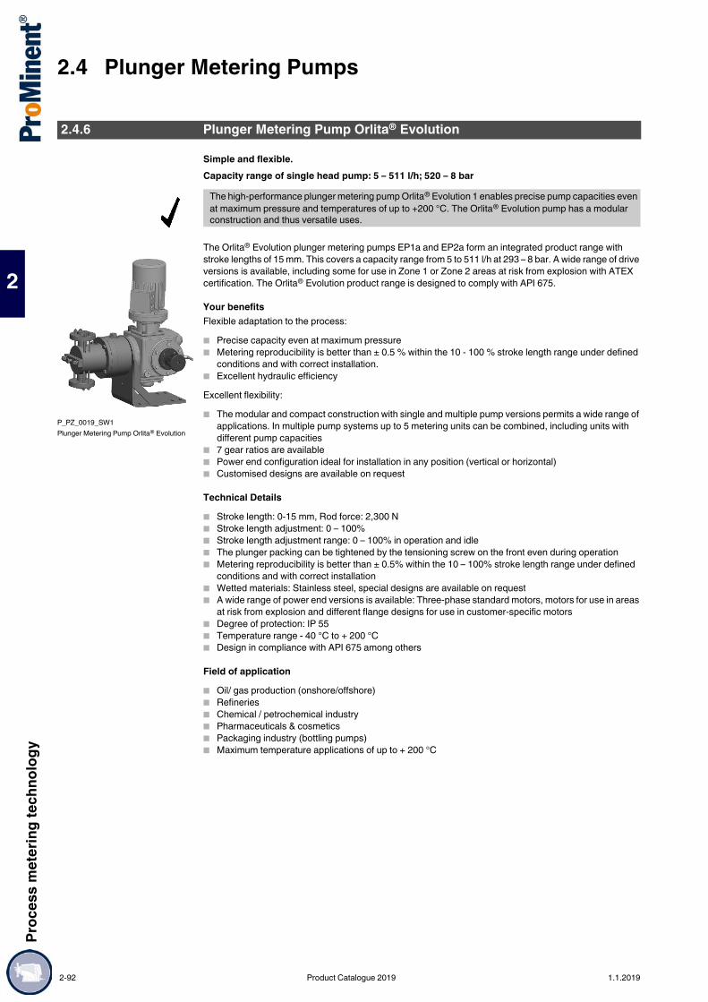
2.4 Plunger Metering PumpsPr
oces
s met
ering
tech
nolog
y
2
Simple and flexible.Capacity range of single head pump: 5 – 511 l/h; 520 – 8 bar
The Orlita® Evolution plunger metering pumps EP1a and EP2a form an integrated product range with stroke lengths of 15 mm. This covers a capacity range from 5 to 511 l/h at 293 – 8 bar. A wide range of drive versions is available, including some for use in Zone 1 or Zone 2 areas at risk from explosion with ATEX certification. The Orlita® Evolution product range is designed to comply with API 675.
Your benefitsFlexible adaptation to the process: Precise capacity even at maximum pressure Metering reproducibility is better than ± 0.5 % within the 10 - 100 % stroke length range under defined
conditions and with correct installation. Excellent hydraulic efficiencyExcellent flexibility: The modular and compact construction with single and multiple pump versions permits a wide range of
applications. In multiple pump systems up to 5 metering units can be combined, including units with different pump capacities
7 gear ratios are available Power end configuration ideal for installation in any position (vertical or horizontal) Customised designs are available on request
Technical Details Stroke length: 0-15 mm, Rod force: 2,300 N Stroke length adjustment: 0 – 100% Stroke length adjustment range: 0 – 100% in operation and idle The plunger packing can be tightened by the tensioning screw on the front even during operation Metering reproducibility is better than ± 0.5% within the 10 – 100% stroke length range under defined
conditions and with correct installation Wetted materials: Stainless steel, special designs are available on request A wide range of power end versions is available: Three-phase standard motors, motors for use in areas
at risk from explosion and different flange designs for use in customer-specific motors Degree of protection: IP 55 Temperature range - 40 °C to + 200 °C Design in compliance with API 675 among others
Field of application Oil/ gas production (onshore/offshore) Refineries Chemical / petrochemical industry Pharmaceuticals & cosmetics Packaging industry (bottling pumps) Maximum temperature applications of up to + 200 °C
2.4.6 Plunger Metering Pump Orlita® Evolution
The high-performance plunger metering pump Orlita® Evolution 1 enables precise pump capacities even at maximum pressure and temperatures of up to +200 °C. The Orlita® Evolution pump has a modular construction and thus versatile uses.
P_PZ_0019_SW1Plunger Metering Pump Orlita® Evolution
2-92 Product Catalogue 2019 1.1.2019

Proc
ess m
eter
ing te
chno
logy
2.4 Plunger Metering Pumps
2
Technical data for EP1a single pump 50 Hz SST
Technical data for EP1a single pump 60 Hz SST
Note:Abridged presentation of our complete product range. Other piston diameters (8-60 mm) on request.
Materials in Contact With the MediumBall valve DN 6 – DN 10
Plate valve DN 16 – DN 20
Further material versions and details available on request.
Plung-er Ø
Strokevolume
Theoretical pump capacity in l/h at strokes/min (50 Hz) Max.pres-sure
Efficiency at Efficiency at Standard type of valve
73 [2] 97 [3] 116 [4] 145 [5] 165 [6] 181 [7] 201 [8]
mm ml/stroke
l/h l/h l/h l/h l/h l/h l/h bar 100%pressure
50%pressure
10 1.18 5.2 6.9 8.2 10.2 11.7 12.8 14.2 293 0.89 0.93 DN 612 1.70 7.4 9.9 11.8 14.8 16.8 18.4 20.5 203 0.89 0.93 DN 614 2.31 10.1 13.4 16.1 20.1 22.9 25.1 27.8 149 0.89 0.93 DN 617 3.40 14.9 19.8 23.7 29.6 33.7 37.0 41.1 101 0.90 0.90 DN 1021 5.20 22.8 30.3 36.2 45.2 51.4 56.4 62.7 66 0.93 0.95 DN 1025 7.36 32.2 42.9 51.2 64.1 72.9 80.0 88.8 47 0.93 0.95 DN 1029 9.91 43.4 57.7 69.0 86.2 98.1 107.6 119.5 35 0.96 0.98 DN 1032 12.06 52.8 70.2 84.0 105.0 119.4 131.0 145.4 29 0.96 0.98 DN 1638 17.01 74.5 99.0 118.4 148.0 168.4 184.7 205.2 20 0.96 0.98 DN 1644 22.81 99.9 132.7 158.7 198.4 225.8 247.7 275.1 15 0.96 0.98 DN 1650 29.45 129.0 171.4 205.0 256.2 291.6 319.9 355.2 12 0.96 0.98 DN 1658 39.63 173.6 230.7 275.8 344.8 392.3 430.4 478.0 9 0.96 0.98 DN 1660 42.41 185.8 246.8 295.2 369.0 419.9 460.6 511.5 8 0.96 0.98 DN 16
Plung-er Ø
Strokevolume
Theoretical pump capacity in l/h at strokes/min (60 Hz) Max.pres-sure
Efficiency at Efficiency at Standard type of valve
88 [2] 117 [3] 140 [4] 175 [5] 199 [6]
mm ml/stroke
l/h l/h l/h l/h l/h bar 100%pressure
50%pressure
10 1.18 6.2 8.3 9.9 12.4 14.1 293 0.89 0.93 DN 612 1.70 9.0 11.9 14.3 17.8 20.3 203 0.89 0.93 DN 614 2.31 12.2 16.2 19.4 24.2 27.6 149 0.89 0.93 DN 617 3.40 18.0 23.9 28.6 35.7 40.7 101 0.90 0.90 DN 1021 5.20 27.4 36.5 43.6 54.6 62.0 66 0.93 0.95 DN 1025 7.36 38.9 51.7 61.9 77.3 87.9 47 0.93 0.95 DN 1029 9.91 52.3 69.6 83.2 104.0 118.3 35 0.96 0.98 DN 1032 12.06 63.7 84.7 101.3 126.7 144.0 29 0.96 0.98 DN 1638 17.01 89.8 119.4 142.9 178.6 203.1 20 0.96 0.98 DN 1644 22.81 120.4 160.1 191.6 239.5 272.3 15 0.96 0.98 DN 1650 29.45 155.5 206.8 247.4 309.3 351.7 12 0.96 0.98 DN 1658 39.63 209.3 278.2 332.9 416.1 473.2 9 0.96 0.98 DN 1660 42.41 223.9 297.7 356.3 445.3 506.4 8 0.96 0.98 DN 16
Suction/ pressure connector
Valve/ head seal Valve ball Valve seat Valve housing Clamp ring
DN 6 (double ball) Stainless steel 1.4404
Stainless steel 1.4404
SiN ceramic Stainless steel 1.4404
Stainless steel 1.4404
Hastelloy C4
DN 10 (single ball) Stainless steel 1.4404
Stainless steel 1.4404
Al2O3 ceramic Stainless steel 1.4404
Stainless steel 1.4404
Hastelloy C4
Suction/ pressure connector
Valve/ head seal Valve plate Valve seat Valve housing
DN 16/DN 20 Stainless steel 1.4404 Stainless steel 1.4571 Stainless steel 1.4462 Stainless steel 1.4404 Stainless steel 1.4404
1.1.2019 Product Catalogue 2019 2-93
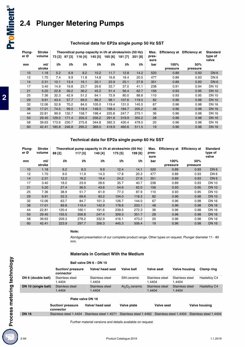
2.4 Plunger Metering PumpsPr
oces
s met
ering
tech
nolog
y
2
Technical data for EP2a single pump 50 Hz SST
Technical data for EP2a single pump 60 Hz SST
Note:Abridged presentation of our complete product range. Other types on request. Plunger diameter 11 - 80 mm.
Materials in Contact With the MediumBall valve DN 6 – DN 10
Plate valve DN 16
Further material versions and details available on request.
Plung-er Ø
Strokevolume
Theoretical pump capacity in l/h at strokes/min (50 Hz) Max.pres-sure
Efficiency at Efficiency at Standard type of valve
73 [2] 97 [3] 116 [4] 145 [5] 165 [6] 181 [7] 201 [8]
mm ml/stroke
l/h l/h l/h l/h l/h l/h l/h bar 100%pressure
50%pressure
10 1.18 5.2 6.9 8.2 10.2 11.7 12.8 14.2 520 0.89 0.93 DN 612 1.70 7.4 9.9 11.8 14.8 16.8 18.4 20.5 477 0.89 0.93 DN 614 2.31 10.1 13.4 16.1 20.1 22.9 25.1 27.8 351 0.89 0.93 DN 617 3.40 14.9 19.8 23.7 29.6 33.7 37.0 41.1 238 0.91 0.94 DN 1021 5.20 22.8 30.2 36.2 45.2 51.4 56.4 62.7 156 0.93 0.95 DN 1025 7.36 32.3 42.9 51.2 64.1 72.9 80.0 88.8 110 0.93 0.95 DN 1029 9.91 43.4 57.7 69.0 86.2 98.1 107.6 119.5 82 0.96 0.98 DN 1032 12.06 52.8 70.2 84.0 105.0 119.4 131.0 145.5 67 0.96 0.98 DN 1638 17.01 74.5 99.0 118.4 148.0 168.4 184.7 205.2 48 0.96 0.98 DN 1644 22.81 99.9 132.7 158.7 198.4 225.8 247.7 275.1 36 0.96 0.98 DN 1650 29.45 129.0 171.4 205.0 256.2 291.6 319.9 355.2 28 0.96 0.98 DN 1658 39.63 173.6 230.7 275.8 344.8 392.3 430.4 478.0 20 0.96 0.98 DN 1660 42.41 185.8 246.8 295.2 369.0 419.9 460.6 511.5 19 0.96 0.98 DN 16
Plung-er Ø
Strokevolume
Theoretical pump capacity in l/h at strokes/min (60 Hz) Max.pres-sure
Efficiency at Efficiency at Standard type of valve
88 [2] 117 [3] 140 [4] 175 [5] 199 [6]
mm ml/stroke
l/h l/h l/h l/h l/h bar 100%pressure
50%pressure
10 1.18 6.2 8.3 9.9 12.4 14.1 520 0.89 0.93 DN 612 1.70 9.0 11.9 14.3 17.8 20.3 477 0.89 0.93 DN 614 2.31 12.2 16.2 19.4 24.2 27.6 351 0.89 0.93 DN 617 3.40 18.0 23.9 28.6 35.7 40.7 238 0.89 0.93 DN 1021 5.20 27.4 36.5 43.6 54.6 62.0 156 0.93 0.95 DN 1025 7.36 38.9 51.7 61.9 77.3 87.9 110 0.93 0.95 DN 1029 9.91 52.3 69.6 83.2 104.0 118.3 82 0.96 0.98 DN 1032 12.06 63.7 84.7 101.3 126.7 144.0 67 0.96 0.98 DN 1638 17.01 89.8 119.4 142.9 178.6 203.1 48 0.96 0.98 DN 1644 22.81 120.4 160.1 191.6 239.5 272.3 36 0.96 0.98 DN 1650 29.45 155.5 206.8 247.4 309.3 351.7 28 0.96 0.98 DN 1658 39.63 209.3 278.2 332.9 416.1 473.2 20 0.96 0.98 DN 1660 42.41 223.9 297.7 356.3 445.3 506.4 19 0.96 0.98 DN 16
Suction/ pressure connector
Valve/ head seal Valve ball Valve seat Valve housing Clamp ring
DN 6 (double ball) Stainless steel 1.4404
Stainless steel 1.4404
SiN ceramic Stainless steel 1.4404
Stainless steel 1.4404
Hastelloy C4
DN 10 (single ball) Stainless steel 1.4404
Stainless steel 1.4404
Al2O3 ceramic Stainless steel 1.4404
Stainless steel 1.4404
Hastelloy C4
Suction/ pressure connector
Valve/ head seal Valve plate Valve seat Valve housing
DN 16 Stainless steel 1.4404 Stainless steel 1.4571 Stainless steel 1.4462 Stainless steel 1.4404 Stainless steel 1.4404
2-94 Product Catalogue 2019 1.1.2019

Proc
ess m
eter
ing te
chno
logy
2.4 Plunger Metering Pumps
2
Orlita® PS - simple, robust and reliable.Capacity range of single head pump: 0 – 37,000 l/h; 400 – 4 bar
ORLITA® PS plunger metering pumps (PS 18 to PS 1400) with a stroke length of 15 to 60 mm provide a capacity ranging from 0 to 37,000 l/h at 400 – 4 bar. A wide range of drive versions is available, including some for use in Exe and Exde areas with ATEX certification. The Orlita® PS product range is designed to comply with API 675. Its modular construction permits the free combination of drives, power ends and dosing heads, producing a pump for a range of different feed rates and media operating at different working pressures.
Your benefitsFlexible adaptation to the process: Precise capacity even at maximum pressure Metering reproducibility is better than ± 0.5 % within the 10-100% stroke length range under defined
conditions and with correct installation. Cone valves for use as suction and/or discharge valves with minimal wear, good self-cleaning and low
pressure loss (NPSHR) Excellent hydraulic efficiencyExcellent flexibility: The modular construction ensures a wide range of uses It is possible to combine up to 6 metering units, even with different pump capacities, in multiple pump
systems 6 different gear ratios are available Power end configuration ideal for installation in any position (vertical or horizontal) Customised designs are available on request
Technical Details PS 18 – Stroke length: 0-15 mm, Rod force: 1,750 N PS 35 – Stroke length: 0-20 mm, Rod force: 3,500 N PS 80 – Stroke length: 0-20 mm, Rod force: 14,000 N PS 180 – Stroke length: 0-40 mm, Rod force: 18,000 N PS 600 – Stroke length: 0-40 mm, Rod force: 40,000 N PS 1400 – Stroke length: 0-60 mm, Rod force: 60,000 N Stroke length adjustment range: 0 – 100% in operation and idle The plunger packing can be tightened by the tensioning screw on the front even during operation Metering reproducibility is better than ± 0.5 % within the 10 – 100% stroke length range under defined
conditions and with correct installation Wetted materials: Stainless steel, special designs are available on request A wide range of power end versions is available: Three-phase standard motors, motors for use in Exe
and Exde areas and different flange designs for use in customer-specific motors Degree of protection: IP 55 Temperature range - 40 °C to + 400 °C Design in compliance with API 675 among others
Field of application Oil/ gas production (onshore/offshore) Refineries Chemical/Petrochemical industry Pharmaceuticals & cosmetics Packaging industry (bottling pumps) Maximum temperature applications of up to +400 °C
2.4.7 Plunger Metering Pump Orlita® PS
The high-performance plunger metering pump ORLITA® PS enables precise pump capacities even at maximum pressure and temperatures of up to +400 °C. The ORLITA® PS pump has a modular construction and thus versatile uses.
P_ORL_071_SW1Orlita® PS 18-36
P_ORL_072_SW1Orlita® PS 80-30
P_ORL_073_SW1Orlita® PS 18-12 high-temperature
P_ORL_074_SW1Orlita® PS 35-7-7
P_ORL_075_SW1Orlita® PS 600-40-40-40
1.1.2019 Product Catalogue 2019 2-95

2.4 Plunger Metering PumpsPr
oces
s met
ering
tech
nolog
y
2
Technical Data
Important note:All performance data is stated at 50 Hz motor frequencyAbridged presentation of our complete product range. Other types on request
Pump type
PlungerØ
Strokevolume
Max. capacity (theo.) in l/hat strokes/min (50 Hz)
Max.pressure
58 73 91 112 145 207 mm ml/stroke l/h l/h l/h l/h l/h l/h bar
PS 18/ 5 0.29 1.0 1.2 1.6 1.9 2.5 3.6 250PS 18/ 6 0.42 1.4 1.8 2.3 2.8 3.6 5.2 250PS 18/ 7 0.58 2.0 2.5 3.1 3.8 5.0 7.1 250PS 18/ 8 0.75 2.6 3.2 4.1 5.0 6.5 9.3 250PS 18/ 10 1.18 4.1 5.1 6.4 7.8 10.2 14.6 200PS 18/ 12 1.70 5.9 7.3 9.2 11.3 14.7 21.0 139PS 18/ 16 3.02 10.5 13.1 16.4 20.1 26.2 37.4 78PS 18/ 20 4.71 16.4 20.5 25.6 31.5 41.0 58.5 50PS 18/ 25 7.36 25.6 32.0 40.0 49.2 64.0 91.5 32PS 18/ 30 10.60 36.9 46.1 57.6 70.9 92.2 131.7 16PS 18/ 36 15.27 53.1 66.4 83.0 102.1 132.8 189.7 15PS 18/ 40 18.85 65.6 82.0 102.4 126.1 163.9 234.2 10PS 18/ 50 29.45 102.4 128.1 160.1 197.1 256.2 366.0 8
Pump type
PlungerØ
Strokevolume
Max. capacity (theo.) in l/hat strokes/min (50 Hz)
Max.pressure
58 73 91 112 145 207 mm ml/stroke l/h l/h l/h l/h l/h l/h bar
PS 35/ 7 0.77 2.6 3.3 4.1 5.1 6.7 9.5 630PS 35/ 8 1.01 3.5 4.3 5.4 6.7 8.7 12.4 400PS 35/ 10 1.57 5.4 6.8 8.5 10.5 13.6 19.5 400PS 35/ 12 2.26 7.8 9.8 12.3 15.1 19.6 28.1 250PS 35/ 16 4.02 13.9 17.4 21.8 26.9 34.9 49.9 156PS 35/ 20 6.28 21.8 27.3 34.1 42.0 54.6 78.0 100PS 35/ 25 9.82 34.1 42.7 53.3 65.7 85.4 122.0 64PS 35/ 30 14.14 49.2 61.5 76.8 94.6 122.9 175.7 44PS 35/ 36 20.36 70.8 88.5 110.6 136.2 177.1 253.0 30PS 35/ 40 25.13 87.4 109.3 136.6 168.2 218.6 312.3 25PS 35/ 50 39.27 136.6 170.8 213.5 262.8 341.6 488.0 16PS 35/ 65 66.37 230.9 288.6 360.8 444.1 577.3 824.8 9PS 35/ 80 100.53 349.8 437.3 546.6 672.7 874.6 1,249.4 6PS 35/ 100 157.08 546.6 683.3 854.1 1,051.2 1,366.5 1,952.2 4
Pump type
PlungerØ
Strokevolume
Max. capacity (theo.) in l/hat strokes/min (50 Hz)
Max.pressure
78 98 122 134 155 182 193 mm ml/stroke l/h l/h l/h l/h l/h l/h l/h bar
PS 80/ 20 6.28 29 37 46 50 58 68 72 400PS 80/ 25 9.82 45 57 71 79 91 107 113 250PS 80/ 30 14.14 66 83 103 113 131 154 163 178PS 80/ 36 20.36 95 119 149 164 189 222 235 123PS 80/ 40 25.13 117 148 184 202 233 274 290 100PS 80/ 50 39.27 183 231 287 316 365 428 453 64PS 80/ 60 56.55 264 333 414 455 526 617 653 44PS 80/ 65 66.37 310 390 486 535 617 724 766 37PS 80/ 80 100.53 470 592 736 810 935 1,097 1,161 25PS 80/ 100 157.08 734 925 1,150 1,266 1,461 1,714 1,814 16PS 80/ 125 245.44 1,148 1,445 1,797 1,978 2,283 2,679 2,835 10PS 80/ 140 307.88 1,440 1,813 2,254 2,482 2,864 3,360 3,557 8PS 80/ 160 402.12 1,880 2,368 2,944 3,242 3,741 4,389 4,646 6
2-96 Product Catalogue 2019 1.1.2019

Proc
ess m
eter
ing te
chno
logy
2.4 Plunger Metering Pumps
2
Important note:All performance data is stated at 50 Hz motor frequencyAbridged presentation of our complete product range. Other types on request
Pump type
PlungerØ
Strokevolume
Max. capacity (theo.) in l/h at strokes/min (50 Hz) Max.pressure
107 117 134 152 171 200 mm ml/stroke l/h l/h l/h l/h l/h l/h bar
PS 180/ 30 28.27 181 199 226 257 290 339 229PS 180/ 36 40.72 262 286 326 370 417 489 159PS 180/ 40 50.27 323 353 403 457 515 604 125PS 180/ 50 78.54 505 552 630 714 805 943 80PS 180/ 54 91.61 589 644 735 833 939 1,100 70PS 180/ 65 132.73 854 934 1,065 1,207 1,361 1,594 48PS 180/ 70 153.94 990 1,083 1,235 1,400 1,579 1,849 40PS 180/ 80 201.06 1,293 1,415 1,613 1,829 2,062 2,416 32PS 180/ 94 277.59 1,786 1,953 2,227 2,526 2,847 3,335 23PS 180/ 125 490.87 3,158 3,455 3,939 4,467 5,036 5,898 13PS 180/ 140 615.75 3,962 4,334 4,941 5,603 6,317 7,399 10PS 180/ 160 804.25 5,175 5,660 6,454 7,318 8,251 9,664 8PS 180/ 200 1,256.64 8,086 8,845 10,085 11,435 12,892 15,100 5
Pump type
PlungerØ
Strokevolume
Max. capacity (theo.) in l/h at strokes/min (50 Hz) Max.pressure
99 117 134 156 173 204 mm ml/stroke l/h l/h l/h l/h l/h l/h bar
PS 600/ 30 28.27 168 198 227 264 293 345 400PS 600/ 36 40.27 242 285 327 381 422 497 353PS 600/ 40 50.27 299 352 403 470 521 614 286PS 600/ 50 78.54 467 551 630 735 814 959 183PS 600/ 54 91.61 545 643 735 857 949 1,119 157PS 600/ 65 132.73 789 932 1,067 1,243 1,376 1,621 100PS 600/ 70 153.94 916 1,080 1,236 1,441 1,596 1,880 93PS 600/ 80 201.06 1,196 1,411 1,616 1,882 2,084 2,456 71PS 600/ 94 277.59 1,651 1,949 2,229 2,599 2,878 3,391 51PS 600/ 125 490.87 2,921 3,446 3,946 4,596 5,090 5,998 29PS 600/ 140 615.75 3,664 4,323 4,951 5,766 6,385 7,523 23PS 600/ 160 804.25 4,785 5,647 6,466 7,531 8,339 9,827 16PS 600/ 200 1,256.64 7,477 8,823 10,104 11,768 13,030 15,354 11
Pump type
PlungerØ
Strokevolume
Max. capacity (theo.) in l/h at strokes/min (50 Hz) Max.pressure
93 106 125 143 169 191 mm ml/stroke l/h l/h l/h l/h l/h l/h bar
PS 1400/ 40 75.40 419 480 565 647 766 864 400PS 1400/ 50 117.81 654 750 884 1,011 1,197 1,350 275PS 1400/ 60 169.65 943 1,080 1,273 1,456 1,724 1,944 190PS 1400/ 70 230.91 1,283 1,470 1,733 1,983 2,346 2,646 140PS 1400/ 80 301.59 1,676 1,920 2,263 2,590 3,065 3,456 107PS 1400/ 94 416.39 2,314 2,651 3,125 3,576 4,231 4,772 77PS 1400/ 125 736.31 4,093 4,689 5,527 6,323 7,483 8,439 44PS 1400/ 140 923.63 5,134 5,882 6,933 7,932 9,387 10,587 35PS 1400/ 160 1,206.37 6,706 7,683 9,055 10,360 12,261 13,827 25PS 1400/ 200 1,884.96 10,478 12,005 14,149 16,188 19,157 21,606 17PS 1400/ 280 3,694.51 20,538 23,530 27,732 31,729 37,549 42,348 8
1.1.2019 Product Catalogue 2019 2-97
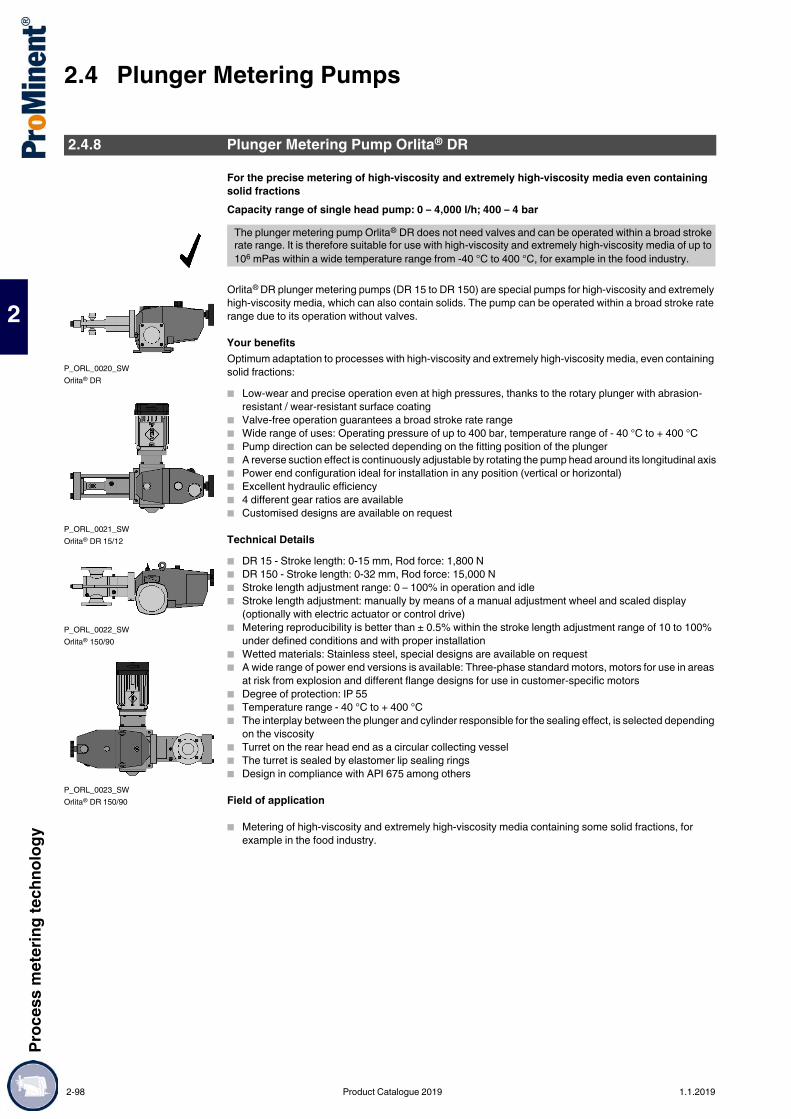
2.4 Plunger Metering PumpsPr
oces
s met
ering
tech
nolog
y
2
For the precise metering of high-viscosity and extremely high-viscosity media even containing solid fractionsCapacity range of single head pump: 0 – 4,000 l/h; 400 – 4 bar
Orlita® DR plunger metering pumps (DR 15 to DR 150) are special pumps for high-viscosity and extremely high-viscosity media, which can also contain solids. The pump can be operated within a broad stroke rate range due to its operation without valves.
Your benefitsOptimum adaptation to processes with high-viscosity and extremely high-viscosity media, even containing solid fractions: Low-wear and precise operation even at high pressures, thanks to the rotary plunger with abrasion-
resistant / wear-resistant surface coating Valve-free operation guarantees a broad stroke rate range Wide range of uses: Operating pressure of up to 400 bar, temperature range of - 40 °C to + 400 °C Pump direction can be selected depending on the fitting position of the plunger A reverse suction effect is continuously adjustable by rotating the pump head around its longitudinal axis Power end configuration ideal for installation in any position (vertical or horizontal) Excellent hydraulic efficiency 4 different gear ratios are available Customised designs are available on request
Technical Details DR 15 - Stroke length: 0-15 mm, Rod force: 1,800 N DR 150 - Stroke length: 0-32 mm, Rod force: 15,000 N Stroke length adjustment range: 0 – 100% in operation and idle Stroke length adjustment: manually by means of a manual adjustment wheel and scaled display
(optionally with electric actuator or control drive) Metering reproducibility is better than ± 0.5% within the stroke length adjustment range of 10 to 100%
under defined conditions and with proper installation Wetted materials: Stainless steel, special designs are available on request A wide range of power end versions is available: Three-phase standard motors, motors for use in areas
at risk from explosion and different flange designs for use in customer-specific motors Degree of protection: IP 55 Temperature range - 40 °C to + 400 °C The interplay between the plunger and cylinder responsible for the sealing effect, is selected depending
on the viscosity Turret on the rear head end as a circular collecting vessel The turret is sealed by elastomer lip sealing rings Design in compliance with API 675 among others
Field of application
Metering of high-viscosity and extremely high-viscosity media containing some solid fractions, for example in the food industry.
2.4.8 Plunger Metering Pump Orlita® DR
The plunger metering pump Orlita® DR does not need valves and can be operated within a broad stroke rate range. It is therefore suitable for use with high-viscosity and extremely high-viscosity media of up to 106 mPas within a wide temperature range from -40 °C to 400 °C, for example in the food industry.
P_ORL_0020_SWOrlita® DR
P_ORL_0021_SWOrlita® DR 15/12
P_ORL_0022_SWOrlita® 150/90
P_ORL_0023_SWOrlita® DR 150/90
2-98 Product Catalogue 2019 1.1.2019

Proc
ess m
eter
ing te
chno
logy
2.4 Plunger Metering Pumps
2
Technical Data
Important note:All performance data is stated at 50 Hz motor frequencyAbridged presentation of our complete product range. Other types on request
Pump type PlungerØ
Strokevolume
Capacity max. (theo.) in l/hat strokes/min (50 Hz)
Max.pressure
58 77 116 mm ml/stroke l/h l/h l/h bar
DR 15/ 7 0.58 2.0 2.6 4.0 400DR 15/ 12 1.70 5.9 7.8 11.8 159DR 15/ 18 3.82 13.2 17.7 26.5 70DR 15/ 25 7.36 25.6 34.1 51.2 36DR 15/ 36 15.27 53.1 70.8 106.2 17DR 15/ 50 29.45 102.4 136.6 204.9 9DR 15/ 70 57.73 200.8 267.8 401.7 4
Pump type PlungerØ
Strokevolume
Capacity max. (theo.) in l/hat strokes/min (50 Hz)
Max.pressure
58 77 116 145 mm ml/stroke l/h l/h l/h l/h bar
DR 150/ 12 3.62 12.5 16.7 25.1 31.4 400DR 150/ 18 8.14 28.3 37.7 56.6 70.8 400DR 150/ 25 15.71 54.6 72.8 109.3 136.6 250DR 150/ 36 32.57 113.3 151.1 226.7 283.3 147DR 150/ 50 62.83 218.6 291.5 437.3 546.6 76DR 150/ 70 123.15 428.5 571.4 857.1 1,071.4 38DR 150/ 90 203.58 708.4 944.5 1,416.8 1,771.1 23DR 150/ 120 361.91 1,259.4 1,679.2 2,518.9 3,148.6 13DR 150/ 140 492.60 1,714.2 2,285.6 3,428.5 4,285.6 9
1.1.2019 Product Catalogue 2019 2-99

2.5 Process Hydraulic Diaphragm PumpsPr
oces
s met
ering
tech
nolog
y
2
2.5Process Hydraulic Diaphragm Pumps
Maximum process reliability in accordance with API 674.Capacity range per pump head: 3 – 511 l/h, 400 – 8 bar
Orlita® Evolution hydraulic diaphragm metering pumps ER1a, EF2F, EF3F and EF4F form an integrated product range with stroke lengths of 15 to 40 mm. This covers the capacity range from 3 to 7,400 l/h at 400 – 10 bar. A wide range of drive versions is available, including some for use in Zone 1 or Zone 2 areas at risk from explosion with ATEX certification. The Orlita® Evolution product range is designed to comply with API 674.
Your benefitsMaximum process reliability: PTFE multi-layer diaphragm with integral diaphragm rupture warning system Integral hydraulic relief valve The new diaphragm position control protects against impermissible operating statuses (e.g. no damage
in the event of a blockage on the suction or discharge side) Metering reproducibility is better than ± 1% under defined conditions and with proper installation Continuous bleeding of the oil chamber ensures reliable operationExcellent flexibility: The modular and compact construction with single and multiple pump versions permits a wide range of
applications. In multiple pump systems up to 5 metering units can be combined, including units with different pump capacities
7 gear ratios are available Power end configuration ideal for installation in any position (vertical or horizontal) Customised designs are available on request
Technical Details Stroke length: 15 mm (Evo 1, Evo 2), 25 mm (Evo 3), 40 mm (Evo 4)
Rod force: 2,300 N (Evo 1), 5,400 N (Evo 2), 8,000 N (Evo 3), 15,700 N (Evo 4) Metering reproducibility is better than ± 1% under defined conditions and with proper installation PTFE multi-layer diaphragm with electrical diaphragm rupture warning system via a contact Integrated hydraulic relief and bleed valve Wetted materials:
Stainless steel 1.4404, special designs available on requestplastics PVC, PVDF, special designs available on request
A wide range of power end versions is available: Three-phase standard motors also for use in areas at risk from explosion, different flange designs for use of customer-specific motors
Degree of protection: IP 55 Design in compliance with API 674 among others
Field of application Oil and gas industry Metering of reactants and catalysts in the chemical industry Volume-proportional metering of chemicals/additives in the treatment of boiler feed water Level-dependent metering of auxiliary agents in industrial production engineering, for instance hot wax
metering in the production of adhesive strips
2.5.1 Process Hydraulic Diaphragm Metering Pump Orlita® Evolution API 674
The hydraulic diaphragm metering pump Orlita® Evolution API 674 is characterised by a PTFE multilayer diaphragm with integral diaphragm rupture warning and by its unique diaphragm position control. It is very robust and meets the most exacting safety requirements.
P_ORL_0062_SW
P_ORL_0060_SW
P_ORL_0057_SW
2-100 Product Catalogue 2019 1.1.2019

Proc
ess m
eter
ing te
chno
logy
2.5 Process Hydraulic Diaphragm Pumps
2
Orlita® Evolution API 674 with stainless steel liquid endTechnical data for EF1F single head pump 50 Hz SST
Technical data for EF1F single head pump 60 Hz SST
Note:Abridged presentation of our complete product range. Other piston diameters (8-60 mm) on requestMaterials in Contact With the MediumDosing head complete
Ball valve DN 3 – DN 10
Plate valve DN 16
Further material versions and details available on request.
Plunger Ø
Strokevolume
Theoretical pump capacity in l/h at strokes/min (50 Hz) Max.pres-sure
Efficiencyat
Efficiencyat
Standard type of valve73 [2] 97 [3] 116 [4] 145 [5] 165 [6] 181 [7] 201 [8]
mm ml/stroke
l/h l/h l/h l/h l/h l/h l/h bar 100%pressure
50%pressure
8 0.75 3.3 4.4 5.2 6.6 7.5 8.2 9.1 400 0.43 0.69 DN 310 1.18 5.2 6.9 8.2 10.2 11.7 12.8 14.2 293 0.61 0.79 DN 312 1.70 7.4 9.9 11.8 14.8 16.8 18.4 20.5 203 0.77 0.86 DN 614 2.31 10.1 13.4 16.1 20.1 22.9 25.1 27.8 149 0.62 0.80 DN 617 3.40 14.9 19.8 23.7 29.6 33.7 36.9 41.0 101 0.77 0.88 DN 621 5.20 22.8 30.3 36.2 45.2 51.5 56.5 62.7 66 0.85 0.89 DN 1025 7.36 32.2 42.8 51.2 64.0 72.9 79.9 88.8 47 0.90 0.93 DN 1029 9.91 43.4 57.7 69.0 83.2 98.1 107.6 119.5 35 0.95 0.96 DN 1032 12.06 52.8 70.2 83.9 104.9 119.4 131.0 145.4 29 0.89 0.93 DN 1038 17.01 74.5 99.0 118.4 148.0 168.4 184.7 205.1 20 0.93 0.95 DN 1044 22.81 99.9 132.8 158.8 198.4 225.8 247.7 275.1 15 0.94 0.96 DN 1650 29.45 129.0 171.4 205.0 256.2 291.6 319.9 355.2 12 0.95 0.96 DN 1658 39.63 173.6 230.6 275.8 344.8 392.3 430.4 477.9 9 0.95 0.97 DN 16
Plunger Ø
Strokevolume
Theoretical pump capacity in l/h at strokes/min (60 Hz) Max.pres-sure
Efficiencyat
Efficiencyat
Standard type of valve88 [2] 117 [3] 140 [4] 175 [5] 199 [6]
mm ml/stroke
l/h l/h l/h l/h l/h bar 100%pressure
50%pressure
8 0.75 4.0 5.3 6.3 7.9 9.0 400 0.43 0.69 DN 310 1.18 6.2 8.3 9.9 12.4 14.1 293 0.61 0.79 DN 312 1.70 9.0 11.9 14.3 17.8 20.3 203 0.77 0.86 DN 614 2.31 12.2 16.2 19.4 24.3 27.6 149 0.62 0.80 DN 617 3.40 18.0 23.9 28.6 35.7 40.6 101 0.77 0.88 DN 621 5.20 27.5 36.5 43.7 54.6 62.1 66 0.85 0.89 DN 1025 7.36 38.9 51.7 61.8 77.3 87.9 47 0.90 0.93 DN 1029 9.91 52.3 69.6 83.2 104.1 118.3 35 0.95 0.96 DN 1032 12.06 63.7 84.7 101.3 126.6 144.0 29 0.89 0.93 DN 1038 17.01 89.8 119.4 142.9 178.6 203.1 20 0.93 0.95 DN 1044 22.81 120.4 160.1 191.6 239.5 272.4 15 0.94 0.96 DN 1650 29.45 155.5 206.7 247.4 309.2 351.6 12 0.95 0.96 DN 1658 39.63 209.2 278.2 332.9 416.1 473.2 9 0.95 0.97 DN 16
Dosing head Diaphragm retaining screw DiaphragmStainless steel Stainless steel 1.4462 PTFE multi-layer diaphragm
Suction/pressure connector
Valve/head seal Valve ball Valve seat Valve housing Clamp ring
DN 3 (double ball) Stainless steel 1.4404
Stainless steel 1.4404
Al2O3 ceramic Stainless steel 1.4404
Stainless steel 1.4404
Hastelloy C4
DN 6 (double ball) Stainless steel 1.4404
Stainless steel 1.4404
SiN ceramic Stainless steel 1.4404
Stainless steel 1.4404
Hastelloy C4
DN 10 (single ball) Stainless steel 1.4404
Stainless steel 1.4404
Al2O3 ceramic Stainless steel 1.4404
Stainless steel 1.4404
Hastelloy C4
Suction/pressure connector
Valve/head seal Valve plate Valve seat Valve housing
DN 16 Stainless steel 1.4404 Stainless steel 1.4571 Stainless steel 1.4462 Stainless steel 1.4404 Stainless steel 1.4404
1.1.2019 Product Catalogue 2019 2-101

2.5 Process Hydraulic Diaphragm PumpsPr
oces
s met
ering
tech
nolog
y
2
Technical data for EF2F single head pump 50 Hz SST
Technical data for EF2F single head pump 60 Hz SST
Note:Abridged presentation of our complete product range. Other piston diameters (11–80 mm) on request.
Materials in Contact With the MediumDosing head complete
Ball valve DN 3 – DN 10
Plate valve DN 16 – DN 20
Further material versions and details available on request.
Plunger Ø
Strokevolume
Theoretical pump capacity in l/h at strokes/min (50 Hz) Max.pres-sure
Efficiencyat
Efficiencyat
Standard type of valve73 [2] 97 [3] 116 [4] 145 [5] 165 [6] 181 [7] 201 [8]
mm ml/stroke
l/h l/h l/h l/h l/h l/h l/h bar 100%pressure
50%pressure
12 1.70 7.0 10.0 12.0 15.0 17.0 18.0 21.0 400 0.69 0.82 DN 614 2.31 10.1 13.4 16.1 20.1 22.9 25.1 28.0 351 0.35 0.67 DN 617 3.40 15.0 20.0 24.0 30.0 34.0 37.0 41.0 238 0.60 0.79 DN 621 5.20 23.0 30.0 36.0 45.0 51.0 56.0 53.0 156 0.75 0.85 DN 1025 7.36 32.3 43.0 51.3 64.1 73.0 80.0 89.0 110 0.83 0.89 DN 1029 9.91 43.4 58.0 69.0 86.2 98.1 108.0 120.0 82 0.90 0.93 DN 1032 12.06 53.0 70.0 84.0 105.0 119.0 131.0 145.0 67 0.76 0.87 DN 1038 17.01 75.0 99.0 118.0 148.0 168.0 185.0 205.0 48 0.87 0.92 DN 1044 22.81 100.0 133.0 159.0 198.0 226.0 248.0 275.0 36 0.90 0.94 DN 1650 29.45 129.0 171.0 205.0 256.0 292.0 320.0 355.0 28 0.91 0.95 DN 1658 39.63 174.0 231.0 276.0 345.0 392.0 430.0 478.0 20 0.93 0.96 DN 1670 57.73 253.0 336.0 402.0 502.0 572.0 627.0 696.0 14 0.94 0.96 DN 20
Plunger Ø
Strokevolume
Theoretical pump capacity in l/h at strokes/min (60 Hz) Max.pres-sure
Efficiencyat
Efficiencyat
Standard type of valve88 [2] 117 [3] 140 [4] 175 [5] 199 [6]
mm ml/stroke
l/h l/h l/h l/h l/h bar 100%pressure
50%pressure
12 1.70 9.0 12.0 14.0 18.0 20.0 400 0.69 0.82 DN 614 2.31 12.2 16.2 19.0 24.0 28.0 351 0.35 0.67 DN 617 3.40 18.0 24.0 29.0 36.0 41.0 238 0.60 0.79 DN 621 5.20 27.0 37.0 44.0 55.0 62.0 156 0.75 0.85 DN 1025 7.36 39.0 52.0 62.0 77.0 88.0 110 0.83 0.89 DN 1029 9.91 52.3 70.0 83.2 104.0 118.3 82 0.90 0.93 DN 1032 12.06 64.0 85.0 101.0 127.0 144.0 67 0.76 0.87 DN 1038 17.01 90.0 119.0 143.0 179.0 203.0 48 0.87 0.92 DN 1044 22.81 120.0 160.0 192.0 240.0 272.0 36 0.90 0.94 DN 1650 29.45 155.0 207.0 247.0 309.0 352.0 28 0.91 0.95 DN 1658 39.63 209.0 278.0 333.0 416.0 473.0 20 0.93 0.96 DN 1670 57.73 305.0 405.0 485.0 606.0 689.0 14 0.94 0.96 DN 20
Dosing head Diaphragm retaining screw DiaphragmStainless steel 1.4404 Stainless steel 1.4462 PTFE multi-layer diaphragm
Suction/pressure connector
Valve/head seal Valve ball Valve seat Valve housing Clamp ring
DN 3 (double ball) Stainless steel 1.4404 Stainless steel 1.4404
Al2O3 ceramic Stainless steel 1.4404
Stainless steel 1.4404
Hastelloy C4
DN 6 (double ball) Stainless steel 1.4404 Stainless steel 1.4404
SiN ceramic Stainless steel 1.4404
Stainless steel 1.4404
Hastelloy C4
DN 10 (double ball) Stainless steel 1.4404 Stainless steel 1.4404
Al2O3 ceramic Stainless steel 1.4404
Stainless steel 1.4404
Hastelloy C4
Suction/pressure connector
Valve/head seal Valve plate Valve seat Valve housing
DN 16/DN 20 Stainless steel 1.4404 Stainless steel 1.4571 Stainless steel 1.4462 Stainless steel 1.4404 Stainless steel 1.4404
2-102 Product Catalogue 2019 1.1.2019

Proc
ess m
eter
ing te
chno
logy
2.5 Process Hydraulic Diaphragm Pumps
2
Technical data for EF3F single head pump 50 Hz SST
Technical data for EF1F single head pump 60 Hz SST
Note:Abridged presentation of our complete product range. Other piston diameters (14-75 mm) on request.
Materials in Contact With the MediumDosing head complete
Ball valve DN 6 – DN 10
Plate valve DN 16 – DN 25
Further material versions and details available on request.
Plunger Ø
Strokevolume
Theoretical pump capacity in l/h at strokes/min (50 Hz) Max.pressure
Efficiencyat
Efficiencyat
Standard type of valve73 [2] 97 [3] 116 [4] 145 [5] 165 [6] 181 [7] 201 [8]
mm ml/stroke
l/h l/h l/h l/h l/h l/h l/h bar 100%pressure
50%pressure
17 5.67 24.6 32.9 39.4 49.3 56.1 61.7 68.5 352 0.68 0.83 DN 622 0.95 41.3 55.1 66.1 82.6 93.9 103.3 114.8 210 0.87 0.93 DN 625 12.27 53.3 71.1 85.4 106.7 121.3 133.4 148.2 163 0.86 0.92 DN 1030 17.67 77.0 102.0 123.0 174.0 192.0 192.0 213.0 113 0.92 0.95 DN 1034 22.70 99.0 132.0 158.0 197.0 225.0 247.0 274.0 88 0.90 0.94 DN 1638 28.35 123.0 164.0 197.0 247.0 280.0 308.0 343.0 71 0.93 0.95 DN 1644 37.01 165.0 220.0 265.0 331.0 376.0 413.0 459.0 53 0.95 0.97 DN 2050 49.09 214.0 285.0 342.0 427.0 485.0 534.0 593.0 41 0.97 0.98 DN 2058 66.05 287.0 383.0 460.0 575.0 653.0 718.0 798.0 30 0.98 0.99 DN 2063 77.93 341.0 454.0 542.0 678.0 772.0 846.0 940.0 26 0.97 0.98 DN 2570 96.21 419.0 558.0 670.0 837.0 951.0 1,046.0 1,163.0 21 0.98 0.98 DN 2575 100.45 480.0 640.0 768.0 960.0 1,091.0 1,201.0 1,334.0 18 0.98 0.98 DN 25
Plunger Ø
Strokevolume
Theoretical pump capacity in l/h at strokes/min (60 Hz) Max.pressure
Efficiencyat
Efficiencyat
Standard type of valve88 [2] 117 [3] 140 [4] 175 [5] 199 [6]
mm ml/stroke
l/h l/h l/h l/h l/h bar 100%pressure
50%pressure
17 5.67 29.7 39.7 47.6 59.5 67.7 352 0.68 0.83 DN 622 9.50 50.0 67.0 80.0 100.0 113.0 210 0.87 0.93 DN 625 12.27 64.0 86.0 103.0 129.0 146.0 163 0.86 0.92 DN 1030 17.67 93.0 124.0 148.0 186.0 211.0 113 0.92 0.95 DN 1034 22.70 120.0 159.0 191.0 238.0 271.0 88 0.90 0.94 DN 1638 28.35 149.0 198.0 238.0 298.0 338.0 71 0.93 0.95 DN 1650 49.09 258.0 344.0 412.0 515.0 585.0 41 0.97 0.98 DN 2070 96.21 505.0 673.0 808.0 1,010.0 1,148.0 21 0.98 0.98 DN 2575 110.45 580.0 773.0 927.0 1,159.0 1,317.0 18 0.98 0.98 DN 2563 77.93 411.0 547.0 655.0 818.0 930.0 26 0.97 0.98 DN 2544 38.01 200.0 266.0 319.0 399.0 454.0 53 0.95 0.97 DN 2058 66.05 347.0 462.0 555.0 694.0 788.0 30 0.98 0.99 DN 20
Dosing head Diaphragm retaining screw DiaphragmStainless steel 1.4404 Stainless steel 1.4462 PTFE multi-layer diaphragm
Suction/pressure connector
Valve/head seal Valve ball Valve seat Valve housing Clamp ring
DN 6 (double ball) Stainless steel 1.4404 Stainless steel 1.4404
SIN ceramic Stainless steel 1.4404
Stainless steel 1.4404
Hastelloy C4
DN 10 (single ball) Stainless steel 1.4404 Stainless steel 1.4404
Al2O3 ceramic
Stainless steel 1.4404
Stainless steel 1.4404
Hastelloy C4
Suction/pressure connector
Valve/head seal Valve plate Valve seat Valve housing
DN 16/DN 25 Stainless steel 1.4404 Stainless steel 1.4571 Stainless steel 1.4462 Stainless steel 1.4404 Stainless steel 1.4404
1.1.2019 Product Catalogue 2019 2-103

2.5 Process Hydraulic Diaphragm PumpsPr
oces
s met
ering
tech
nolog
y
2
Technical data for EF4F single head pump 50 Hz SST
Technical data for EF4F single head pump 60 Hz SST
Note:Abridged presentation of our complete product range. Additional plunger diameters (22–140 mm) on request.
Materials in Contact With the MediumDosing head complete
Plate valve
Further material versions and details available on request.
Plunger Ø
Strokevolume
Theoretical pump capacity in l/h at strokes/min (50 Hz) Max.pres-sure
Efficiencyat
Efficiencyat
Standard type of valve73 [2] 97 [3] 116 [4] 145 [5] 165 [6] 181 [7] 201 [8]
mm ml/stroke
l/h l/h l/h l/h l/h l/h l/h bar 100%pressure
50%pressure
22 15.21 67.0 89.0 106.0 132.0 151.0 165.0 183.0 400 0.71 0.84 DN 1625 19.63 86.0 114.0 137.0 171.0 194.0 213.0 237.0 320 0.72 0.85 DN 1630 28.27 124.0 165.0 197.0 246.0 280.0 307.0 341.0 222 0.73 0.85 DN 1634 36.32 159.0 211.0 253.0 316.0 360.0 394.0 438.0 172 0.80 0.87 DN 1638 45.36 199.0 264.0 316.0 395.0 449.0 493.0 547.0 138 0.86 0.90 DN 2044 60.82 266.0 354.0 423.0 529.0 602.0 661.0 733.0 103 0.90 0.92 DN 2050 78.54 344.0 457.0 547.0 683.0 778.0 853.0 947.0 80 0.93 0.94 DN 2560 113.10 495.0 658.0 787.0 984.0 1,120.0 1,228.0 1,364.0 55 0.94 0.95 DN 3270 153.94 674.0 896.0 1,071.0 1,339.0 1,524.0 1,672.0 1,857.0 40 0.94 0.95 DN 4086 232.35 1,018.0 1,352.0 1,617.0 2,021.0 2,300.0 2,523.0 2,802.0 27 0.96 0.97 DN 5090 254.47 1,115.0 1,481.0 1,771.0 2,214.0 2,519.0 2,764.0 3,069.0 24 0.96 0.97 DN 50
100 314.16 1,376.0 1,828.0 2,187.0 2,733.0 3,110.0 3,412.0 3,789.0 20 0.97 0.98 DN 50140 615.75 2,697.0 3,584.0 4,286.0 5,357.0 6,096.0 6,687.0 7,426.0 10 0.99 0.99 DN 65
75 176.71 774.0 1,028.0 1,230.0 1,537.0 1,749.0 1,919.0 2,131.0 35 0.95 0.96 DN 40115 415.48 1,820.0 2,418.0 2,892.0 3,615.0 4,113.0 4,512.0 5,011.0 15 0.98 0.99 DN 65130 530.93 2,325.0 3,090.0 3,695.0 4,619.0 5,256.0 5,766.0 6,403.0 12 0.99 0.99 DN 65
Plunger Ø
Strokevolume
Theoretical pump capacity in l/h at strokes/min (60 Hz) Max.pressure
Efficiencyat
Efficiencyat
Standard type of valve88 [2] 117 [3] 140 [4] 175 [5] 199 [6]
mm ml/stroke
l/h l/h l/h l/h l/h bar 100%pressure
50%pressure
22 15.21 80.0 107.0 128.0 160.0 182.0 400 0.71 0.84 DN 1625 19.63 104.0 138.0 165.0 206.0 234.0 320 0.72 0.85 DN 1630 28.27 149.2 198.4 237.4 297.0 337.5 222 0.73 0.85 DN 1634 36.32 192.0 255.0 305.0 381.0 434.0 172 0.80 0.87 DN 1650 78.54 415.0 551.0 660.0 825.0 938.0 80 0.93 0.94 DN 2538 45.36 240.0 318.0 381.0 476.0 542.0 138 0.86 0.90 DN 2044 60.82 321.0 427.0 511.0 639.0 726.0 103 0.90 0.92 DN 20
360 113.10 597.0 794.0 950.0 1,188.0 1,350.0 55 0.94 0.95 DN 3270 153.94 813.0 1,081.0 1,293.0 1,616.0 1,838.0 40 0.94 0.95 DN 4075 176.71 933.0 1,241.0 1,484.0 1,855.0 2,110.0 35 0.95 0.96 DN 4086 232.35 1,227.0 1,631.0 1,952.0 2,440.0 2,774.0 27 0.96 0.97 DN 5090 254.47 1,344.0 1,786.0 2,138.0 2,671.0 3,038.0 24 0.96 0.97 DN 50
100 314.16 1,659.0 2,205.0 2,639.0 3,299.0 3,751.0 20 0.97 0.98 DN 50110 380.13 2,007.0 2,669.0 3,193.0 3,991.0 4,539.0 16 0.98 0.98 DN 50115 415.48 2,194.0 2,917.0 3,490.0 4,363.0 4,961.0 15 0.98 0.99 DN 65130 530.93 2,803.0 3,727.0 4,460.0 5,575.0 6,339.0 12 0.99 0.99 DN 65140 615.75 3,251.0 4,323.0 5,172.0 6,465.0 7,352.0 10 0.99 0.99 DN 65
Dosing head Diaphragm retaining screw DiaphragmStainless steel 1.4404 Stainless steel 1.4462 PTFE multi-layer diaphragm
Suction/pressure connector
Valve/head seal Valve plate Valve seat Valve housing
DN 16 – DN 65 Stainless steel 1.4404 Stainless steel 1.4571 Stainless steel 1.4462 Stainless steel 1.4404 Stainless steel 1.4404
2-104 Product Catalogue 2019 1.1.2019
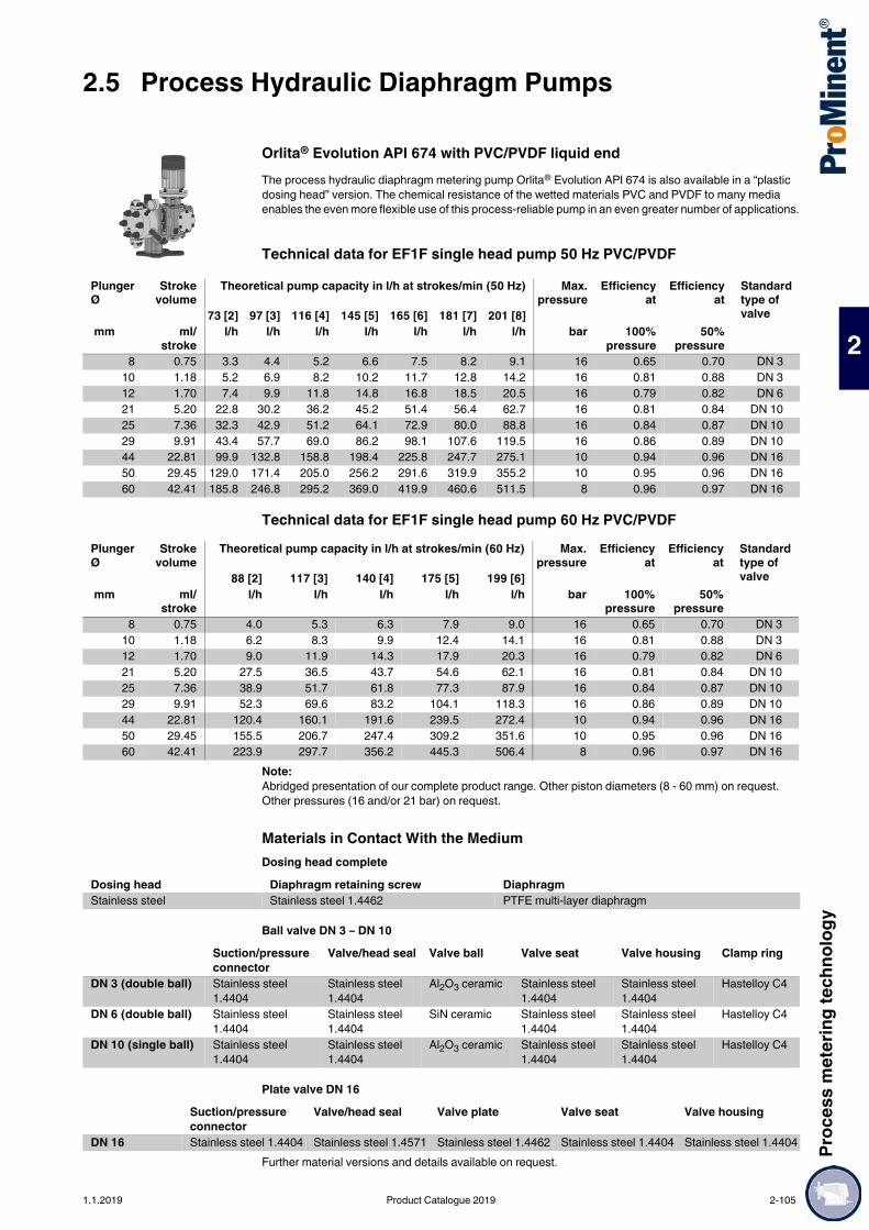
Proc
ess m
eter
ing te
chno
logy
2.5 Process Hydraulic Diaphragm Pumps
2
Orlita® Evolution API 674 with PVC/PVDF liquid endThe process hydraulic diaphragm metering pump Orlita® Evolution API 674 is also available in a “plastic dosing head” version. The chemical resistance of the wetted materials PVC and PVDF to many media enables the even more flexible use of this process-reliable pump in an even greater number of applications.
Technical data for EF1F single head pump 50 Hz PVC/PVDF
Technical data for EF1F single head pump 60 Hz PVC/PVDF
Note:Abridged presentation of our complete product range. Other piston diameters (8 - 60 mm) on request. Other pressures (16 and/or 21 bar) on request.
Materials in Contact With the MediumDosing head complete
Ball valve DN 3 – DN 10
Plate valve DN 16
Further material versions and details available on request.
Plunger Ø
Strokevolume
Theoretical pump capacity in l/h at strokes/min (50 Hz) Max.pressure
Efficiencyat
Efficiencyat
Standard type of valve73 [2] 97 [3] 116 [4] 145 [5] 165 [6] 181 [7] 201 [8]
mm ml/stroke
l/h l/h l/h l/h l/h l/h l/h bar 100%pressure
50%pressure
8 0.75 3.3 4.4 5.2 6.6 7.5 8.2 9.1 16 0.65 0.70 DN 310 1.18 5.2 6.9 8.2 10.2 11.7 12.8 14.2 16 0.81 0.88 DN 312 1.70 7.4 9.9 11.8 14.8 16.8 18.5 20.5 16 0.79 0.82 DN 621 5.20 22.8 30.2 36.2 45.2 51.4 56.4 62.7 16 0.81 0.84 DN 1025 7.36 32.3 42.9 51.2 64.1 72.9 80.0 88.8 16 0.84 0.87 DN 1029 9.91 43.4 57.7 69.0 86.2 98.1 107.6 119.5 16 0.86 0.89 DN 1044 22.81 99.9 132.8 158.8 198.4 225.8 247.7 275.1 10 0.94 0.96 DN 1650 29.45 129.0 171.4 205.0 256.2 291.6 319.9 355.2 10 0.95 0.96 DN 1660 42.41 185.8 246.8 295.2 369.0 419.9 460.6 511.5 8 0.96 0.97 DN 16
Plunger Ø
Strokevolume
Theoretical pump capacity in l/h at strokes/min (60 Hz) Max.pressure
Efficiencyat
Efficiencyat
Standard type of valve88 [2] 117 [3] 140 [4] 175 [5] 199 [6]
mm ml/stroke
l/h l/h l/h l/h l/h bar 100%pressure
50%pressure
8 0.75 4.0 5.3 6.3 7.9 9.0 16 0.65 0.70 DN 310 1.18 6.2 8.3 9.9 12.4 14.1 16 0.81 0.88 DN 312 1.70 9.0 11.9 14.3 17.9 20.3 16 0.79 0.82 DN 621 5.20 27.5 36.5 43.7 54.6 62.1 16 0.81 0.84 DN 1025 7.36 38.9 51.7 61.8 77.3 87.9 16 0.84 0.87 DN 1029 9.91 52.3 69.6 83.2 104.1 118.3 16 0.86 0.89 DN 1044 22.81 120.4 160.1 191.6 239.5 272.4 10 0.94 0.96 DN 1650 29.45 155.5 206.7 247.4 309.2 351.6 10 0.95 0.96 DN 1660 42.41 223.9 297.7 356.2 445.3 506.4 8 0.96 0.97 DN 16
Dosing head Diaphragm retaining screw DiaphragmStainless steel Stainless steel 1.4462 PTFE multi-layer diaphragm
Suction/pressure connector
Valve/head seal Valve ball Valve seat Valve housing Clamp ring
DN 3 (double ball) Stainless steel 1.4404
Stainless steel 1.4404
Al2O3 ceramic Stainless steel 1.4404
Stainless steel 1.4404
Hastelloy C4
DN 6 (double ball) Stainless steel 1.4404
Stainless steel 1.4404
SiN ceramic Stainless steel 1.4404
Stainless steel 1.4404
Hastelloy C4
DN 10 (single ball) Stainless steel 1.4404
Stainless steel 1.4404
Al2O3 ceramic Stainless steel 1.4404
Stainless steel 1.4404
Hastelloy C4
Suction/pressure connector
Valve/head seal Valve plate Valve seat Valve housing
DN 16 Stainless steel 1.4404 Stainless steel 1.4571 Stainless steel 1.4462 Stainless steel 1.4404 Stainless steel 1.4404
1.1.2019 Product Catalogue 2019 2-105
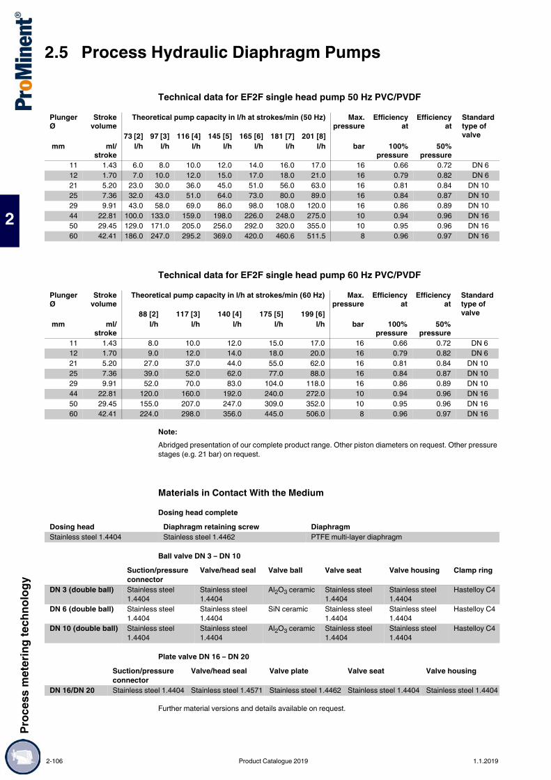
2.5 Process Hydraulic Diaphragm PumpsPr
oces
s met
ering
tech
nolog
y
2
Technical data for EF2F single head pump 50 Hz PVC/PVDF
Technical data for EF2F single head pump 60 Hz PVC/PVDF
Note:Abridged presentation of our complete product range. Other piston diameters on request. Other pressure stages (e.g. 21 bar) on request.
Materials in Contact With the MediumDosing head complete
Ball valve DN 3 – DN 10
Plate valve DN 16 – DN 20
Further material versions and details available on request.
Plunger Ø
Strokevolume
Theoretical pump capacity in l/h at strokes/min (50 Hz) Max.pressure
Efficiencyat
Efficiencyat
Standard type of valve73 [2] 97 [3] 116 [4] 145 [5] 165 [6] 181 [7] 201 [8]
mm ml/stroke
l/h l/h l/h l/h l/h l/h l/h bar 100%pressure
50%pressure
11 1.43 6.0 8.0 10.0 12.0 14.0 16.0 17.0 16 0.66 0.72 DN 612 1.70 7.0 10.0 12.0 15.0 17.0 18.0 21.0 16 0.79 0.82 DN 621 5.20 23.0 30.0 36.0 45.0 51.0 56.0 63.0 16 0.81 0.84 DN 1025 7.36 32.0 43.0 51.0 64.0 73.0 80.0 89.0 16 0.84 0.87 DN 1029 9.91 43.0 58.0 69.0 86.0 98.0 108.0 120.0 16 0.86 0.89 DN 1044 22.81 100.0 133.0 159.0 198.0 226.0 248.0 275.0 10 0.94 0.96 DN 1650 29.45 129.0 171.0 205.0 256.0 292.0 320.0 355.0 10 0.95 0.96 DN 1660 42.41 186.0 247.0 295.2 369.0 420.0 460.6 511.5 8 0.96 0.97 DN 16
Plunger Ø
Strokevolume
Theoretical pump capacity in l/h at strokes/min (60 Hz) Max.pressure
Efficiencyat
Efficiencyat
Standard type of valve88 [2] 117 [3] 140 [4] 175 [5] 199 [6]
mm ml/stroke
l/h l/h l/h l/h l/h bar 100%pressure
50%pressure
11 1.43 8.0 10.0 12.0 15.0 17.0 16 0.66 0.72 DN 612 1.70 9.0 12.0 14.0 18.0 20.0 16 0.79 0.82 DN 621 5.20 27.0 37.0 44.0 55.0 62.0 16 0.81 0.84 DN 1025 7.36 39.0 52.0 62.0 77.0 88.0 16 0.84 0.87 DN 1029 9.91 52.0 70.0 83.0 104.0 118.0 16 0.86 0.89 DN 1044 22.81 120.0 160.0 192.0 240.0 272.0 10 0.94 0.96 DN 1650 29.45 155.0 207.0 247.0 309.0 352.0 10 0.95 0.96 DN 1660 42.41 224.0 298.0 356.0 445.0 506.0 8 0.96 0.97 DN 16
Dosing head Diaphragm retaining screw DiaphragmStainless steel 1.4404 Stainless steel 1.4462 PTFE multi-layer diaphragm
Suction/pressure connector
Valve/head seal Valve ball Valve seat Valve housing Clamp ring
DN 3 (double ball) Stainless steel 1.4404
Stainless steel 1.4404
Al2O3 ceramic Stainless steel 1.4404
Stainless steel 1.4404
Hastelloy C4
DN 6 (double ball) Stainless steel 1.4404
Stainless steel 1.4404
SiN ceramic Stainless steel 1.4404
Stainless steel 1.4404
Hastelloy C4
DN 10 (double ball) Stainless steel 1.4404
Stainless steel 1.4404
Al2O3 ceramic Stainless steel 1.4404
Stainless steel 1.4404
Hastelloy C4
Suction/pressure connector
Valve/head seal Valve plate Valve seat Valve housing
DN 16/DN 20 Stainless steel 1.4404 Stainless steel 1.4571 Stainless steel 1.4462 Stainless steel 1.4404 Stainless steel 1.4404
2-106 Product Catalogue 2019 1.1.2019

Proc
ess m
eter
ing te
chno
logy
2.5 Process Hydraulic Diaphragm Pumps
2
Technical data for EF3F single head pump 50 Hz PVC/PVDF
Technical data for EF3F single head pump 60 Hz PVC/PVDF
Note:Abridged presentation of our complete product range. Other piston diameters on request. Other pressure stages (e.g. 16 bar) on request.
Materials in Contact With the MediumDosing head complete
Ball valve DN 6 – DN 10
Plate valve DN 16 – DN 25
Further material versions and details available on request.
Plunger Ø
Strokevolume
Theoretical pump capacity in l/h at strokes/min (50 Hz) Max.pressure
Efficiencyat
Efficiencyat
Standard type of valve73 [2] 97 [3] 116 [4] 145 [5] 165 [6] 181 [7] 201 [8]
mm ml/stroke
l/h l/h l/h l/h l/h l/h l/h bar 100%pressure
50%pressure
63 77.93 339.0 452.0 542.0 678.0 770.0 848.0 942.0 10 0.95 0.96 DN 2575 110.45 480.0 641.0 769.0 961.0 1,092.0 1,201.0 1,335.0 10 0.97 0.98 DN 2567 88.14 386.0 513.0 613.0 767.0 873.0 957.0 1,063.0 10 0.95 0.96 DN 2570 96.21 419.0 558.0 670.0 837.0 951.0 1,046.0 1,163.0 10 0.96 0.97 DN 25
Plunger Ø
Strokevolume
Theoretical pump capacity in l/h at strokes/min (60 Hz) Max.pressure
Efficiencyat
Efficiencyat
Standard type of valve88 [2] 117 [3] 140 [4] 175 [5] 199 [6]
mm ml/stroke
l/h l/h l/h l/h l/h bar 100%pressure
50%pressure
63 77.93 409.0 546.0 655.0 818.0 930.0 10 0.95 0.96 DN 2575 110.45 583.0 775.0 928.0 1,160.0 1,319.0 10 0.97 0.98 DN 2567 88.14 465.0 619.0 740.0 925.0 1,052.0 10 0.95 0.96 DN 2570 96.21 505.0 673.0 808.0 1,010.0 1,148.0 10 0.96 0.97 DN 25
Dosing head Diaphragm retaining screw DiaphragmStainless steel 1.4404 Stainless steel 1.4462 PTFE multi-layer diaphragm
Suction/pressure connector
Valve/head seal Valve ball Valve seat Valve housing Clamp ring
DN 6 (double ball) Stainless steel 1.4404
Stainless steel 1.4404
SIN ceramic Stainless steel 1.4404
Stainless steel 1.4404
Hastelloy C4
DN 10 (single ball) Stainless steel 1.4404
Stainless steel 1.4404
Al2O3 ceramic Stainless steel 1.4404
Stainless steel 1.4404
Hastelloy C4
Suction/pressure connector
Valve/head seal Valve plate Valve seat Valve housing
DN 16/DN 25 Stainless steel 1.4404 Stainless steel 1.4571 Stainless steel 1.4462 Stainless steel 1.4404 Stainless steel 1.4404
1.1.2019 Product Catalogue 2019 2-107

2.5 Process Hydraulic Diaphragm PumpsPr
oces
s met
ering
tech
nolog
y
2
Technical data for EF4F single head pump 50 Hz PVC/PVDF
Technical data for EF4F single head pump 60 Hz PVC/PVDF
Note:Abridged presentation of our complete product range. Other piston diameters on request. Other pressure stages (16 and/or 21 bar) on request.
Materials in Contact With the MediumDosing head complete
Plate valve
Further material versions and details available on request.
Plunger Ø
Strokevolume
Theoretical pump capacity in l/h at strokes/min (50 Hz) Max.pres-sure
Efficiencyat
Efficiencyat
Standard type of valve73 [2] 97 [3] 116 [4] 145 [5] 165 [6] 181 [7] 201 [8]
mm ml/stroke
l/h l/h l/h l/h l/h l/h l/h bar 100%pressure
50%pressure
70 153.94 674.0 896.0 1,071.0 1,339.0 1,524.0 1,672.0 1,857.0 10 0.94 0.95 DN 4086 232.35 1,018.0 1,352.0 1,617.0 2,021.0 2,300.0 2,523.0 2,802.0 10 0.96 0.97 DN 50
110 380.13 1,665.0 2,212.0 2,646.0 3,307.0 3,763.0 4,128.0 4,584.0 10 0.98 0.98 DN 50140 615.75 2,697.0 3,584.0 4,286.0 5,357.0 6,096.0 6,687.0 7,426.0 10 0.99 0.99 DN 65
Plunger Ø
Strokevolume
Theoretical pump capacity in l/h at strokes/min (60 Hz) Max.pressure
Efficiencyat
Efficiencyat
Standard type of valve88 [2] 117 [3] 140 [4] 175 [5] 199 [6]
mm ml/stroke
l/h l/h l/h l/h l/h bar 100%pressure
50%pressure
70 153.94 813.0 1,081.0 1,293.0 1,616.0 1,838.0 10 0.94 0.95 DN 4086 232.35 1,227.0 1,631.0 2,440.0 2,523.0 1,952.0 10 0.96 0.97 DN 50
110 380.13 2,007.0 2,669.0 3,193.0 3,991.0 4,539.0 10 0.98 0.98 DN 50140 615.75 3,251.0 4,323.0 5,172.0 6,465.0 7,352.0 10 0.99 0.99 DN 65
Dosing head Diaphragm retaining screw DiaphragmStainless steel 1.4404 Stainless steel 1.4462 PTFE multi-layer diaphragm
Suction/pressure connector
Valve/head seal Valve plate Valve seat Valve housing
DN 16 – DN 65 Stainless steel 1.4404 Stainless steel 1.4571 Stainless steel 1.4462
Stainless steel 1.4404
Stainless steel 1.4404
2-108 Product Catalogue 2019 1.1.2019

Proc
ess m
eter
ing te
chno
logy
2.5 Process Hydraulic Diaphragm Pumps
2
The innovative process metering pump with the ideal dimensions and excellent efficiency.Capacity range 424 – 8,000 l/h, 367 – 36 bar
The Zentriplex is an oscillating process diaphragm metering pump, which has a very small footprint thanks to its unconventional design, as the pump and drive unit are mounted above each other to save space. Diaphragm dosing heads and hydraulic units are arranged in a star pattern around the drive unit, resulting in minimised loads and significantly lower material and drive requirements. The Zentriplex is designed in compliance with API 674.
Your benefitsExcellent conservation of resources: Excellent energy efficiency. Diaphragm replacement without dismantling the suction and discharge lines ensures cost-effective
maintenance of the pump Low noise emissions Very quiet thanks to complete balancing of masses Only one connection required by the customer. Collective discharge and suction lines are integrated in
the pump Low flow rate pulsation Customised designs are available on request
Technical Details Stroke length: 40 mm, Rod force: 18,000 N fixed stroke pump Metering reproducibility is better than ± 1% under defined conditions and with proper installation PTFE multi-layer diaphragm with electrical diaphragm rupture warning system via a contact Integrated hydraulic relief and bleed valve Wetted materials: Stainless steel, special designs are available on request A wide range of motor versions is available: Three-phase standard motors with varied adjustment
ranges, motors for use in Exe and Exde areas, different flange designs for use in customer-specific motors
Degree of protection: IP 55 Design in compliance with API 674
Field of application Chemical industry Petrochemical industry Refineries Oil and gas industry
2.5.2 Process Hydraulic Diaphragm Metering Pump Zentriplex API 674
The Zentriplex guarantees excellent performance and provides outstanding efficiency as an oscillating triplex process hydraulic diaphragm pump, with an extremely small footprint thanks to the space-saving arrangement of the pump and drive unit. It also stands out on account of its efficiency, as minimal material and labour are required.
P_PZ_0009_SW1Process diaphragm pump Zentriplex (1= customer-side connection)
1.1.2019 Product Catalogue 2019 2-109

2.5 Process Hydraulic Diaphragm PumpsPr
oces
s met
ering
tech
nolog
y
2
Technical Data
Note:Abridged presentation of our complete product range. Other piston diameters (14 - 75 mm) on request
Materials in Contact With the Medium
Ball valve DN 10
Plate valve DN 15 / DN 20 / DN 25 / DN 32
Further material versions and details available on request.
Motor and Gearbox DataMotors and gearboxes from 7.5 to 15 kW are available for the Zentriplex product range. Further options and details available upon request.
Plunger Ø Strokevolume
Theoretical pump capacity Qthat a stroke rate n in rpm
Max.operatingpressure
Efficiency at Efficiency at Standard type of valve
120 [3] 145 [4] 170 [5] 200 [6] 220 [7] mm ml/
stroke l/h l/h l/h l/h l/h bar 100%
pressure50%
pressure25 58.90 424 512 601 707 778 367 0.78 0.83 DN 1026 63.71 459 554 650 765 841 339 0.78 0.83 DN 1030 84.82 611 738 865 1,018 1,120 255 0.81 0.85 DN 1536 122.15 879 1,063 1,246 1,466 1,612 177 0.84 0.87 DN 2044 182.46 1,314 1,587 1,861 2,190 2,409 118 0.85 0.88 DN 2060 339.29 2,443 2,952 3,461 4,072 4,479 64 0.90 0.92 DN 2570 461.81 3,325 4,018 4,711 5,542 6,096 47 0.90 0.92 DN 3280 603.19 4,343 5,248 6,152 7,238 7,962 36 0.90 0.92 DN 32
Dosing head complete ManifoldDosing head Diaphragm retaining
screwDiaphragm Suction/pressure
connectorSeal, manifold
Stainless steel 1.4404
Stainless steel 1.4462 PTFE multi-layer diaphragm
Stainless steel 1.4571 Viton O-ring with seamless FEP jacket
Suction/pressure connector
Seal valve/head Valve ball Valve seat Valve housing
Stainless steel 1.4571 Stainless steel 1.4571 Al2O3 ceramic Stainless steel 1.4404 Stainless steel 1.4404
Suction/pressure connector
Seal valve/head Valve plate Valve seat Valve housing
Stainless steel 1.4571 Stainless steel 1.4571 Stainless steel 1.4462 Stainless steel 1.4571 Stainless steel 1.4571
Standard gear motor 7.5 kW, 9.2 kW, 11 kW, 15 kW 3 ph, IP 55 400/690V 50/60 Hz Control range 1:5Ex gear motor EExde IICT4 11 kW, 15 kW 3 ph, IP 65 400/690V 50/60 Hz Control range 1:5Standard external gearbox 11 kW...15 kW IP 55 Version according to DIN/ISO standard
flangeStandard external gearbox 11 kW...15 kW IP 55 NEMA flange versionEx gearbox 2 IIGD c,k T4/T120C external 11 kW...15 kW IP 55 Version according to DIN/ISO standard
flangeEx gearbox 2 IIGD c,k T4/T120C external 11 kW...15 kW IP 55 NEMW flange version
2-110 Product Catalogue 2019 1.1.2019

Proc
ess m
eter
ing te
chno
logy
2.6 Accessories for Process Metering Pumps
2
2.6Accessories for Process Metering Pumps
Hydraulic/mechanical accessories for metering pumps such as injection valves and foot valves, can be found in Chapter 1.4.2, sorted by nominal width DN 8 ... DN 40:Please observe the permitted pressure stages or material combinations in your selection. Further accessories are available on request.
To fit metering pumps of the product ranges Sigma, Meta and Makro TZ-HK.Housing and valve spring made of stainless steel no. 1.4571, ball made of stainless steel no. 1.4401, PTFE seals, priming pressure approx. 0.1 bar.Applications90 °C - max. operating pressure, see table
2.6.1 Hydraulic/Mechanical Accessories
2.6.1.1 Foot Valve SST for High-Pressure Metering Pumps
P_AC_0205_SW
G B Rp Ø D Order no. mm mm
DN 10 3/4 70 1/4 41 803730DN 10 3/4 70 3/8 41 803731
2.6.1.2 Injection Valve SST for High-Pressure Metering Pumps
pk_2_028
Max.pressure
G1 G2 Ø D A Order no.
bar mm mmDN 8 320 Rp 1/4 Rp 1/2 42 85 803732DN 10 190 Rp 3/8 Rp 1/2 42 90 803733
1.1.2019 Product Catalogue 2019 2-111

2.6 Accessories for Process Metering PumpsPr
oces
s met
ering
tech
nolog
y
2
Spring-loaded valves, inline version, designed as pump valves, i.e. to cope with a very high number of load cycles. Also suitable for use without pulsation damper.Features: Female thread on both sides or with sealing surface For bracing between 2 flanges PN 200 or PN 400 Settings factory-set Standard design in stainless steel, hastelloy also available on request, as is InconelAlso available heatable on request.
2.6.1.3 Return/Pressure Relief Valve, Spring-loaded
DN Adjustable pressure Construction Order no.6 2.0 bar Ball 10200746 4.0 bar Ball 10192246 8.0 – 9.0 bar Ball 101909710 2.0 bar Cone, fixed 101964910 3.0 – 6.0 bar Cone, adjustable 102305310 8.0 – 14.0 bar Cone, adjustable 102406516 2.0 bar Cone, fixed 101793716 3.0 bar Cone, fixed 103526616 4.5 – 5.4 bar Cone, fixed 101793625 1.0 – 2.0 bar Cone, fixed 1021843
2-112 Product Catalogue 2019 1.1.2019

Proc
ess m
eter
ing te
chno
logy
2.6 Accessories for Process Metering Pumps
2
Regulations:Safety valves are designed to comply with the following regulations: Pressurised Vessel and Steam Boiler Directive TRD 421, 721 TRB 403 AD 2000 Bulletins A2 and A4 DIN EN ISO 4126 Pressure Equipment Directive 97/23/EC ASME Code, Sections II and VIII API 526, 520, 527 OthersThe relevant product-specific certificates are available to prove compliance with these regulations and thus also the safety of the products.Safety valves carry a parts label (specification label) stipulating the following data: Order date (serial no.) Technical data Set pressure VdTÜV Parts test number CE mark with number of nominated centre Further data, e.g. UV stamp with ASME-approved safety valvesInspection / Labelling:Following adjustment and inspection, every safety valve is sealed by the manufacturer.Connectors: NPT threaded connectors, threaded sockets, flange mountings comply with DIN / ANSI. Other connections are available on request.
2.6.1.4 Safety Valve
P_AC_0231_SW
P_AC_0232_SW
Inlet body materialMaterial description X 14 CrNiMo 17-12-2Material no. 1.4404ASME 316L
Dimensions, pressure ranges, weights Standard 10 mmPressure rating at inlet 320 PNPressure rating at outlet 160 PNMin. response pressure 0.1 barMax. response pressure (4373 / 4374) 68 barNarrowest flow cross-section 78.5 mm2
Narrowest flow diameter 10 mmLeg length (outlet / inlet) 30 mm / 33 mmPin length (G 1/2 / G 3/4) 15 mm / 16 mmFlange design 100 mmHeight (H2 / H4) 137/162 mmWeight 1.2 kg
1.1.2019 Product Catalogue 2019 2-113

2.6 Accessories for Process Metering PumpsPr
oces
s met
ering
tech
nolog
y
2
Pulsation dampers with separating membrane / bubble / bellows for providing separation between the gas cushion and metered chemical are used for low-pulsation metering as well as for reducing flow resistance in long metering lines and with viscous media. The response pressure of the gas cushion should be approx. 60-80% of the operating pressure.Important: A pressure relief valve should always be fitted with an adjustable back pressure valve when using a pulsation damper.
Bladder dampers, metal
Further material versions and details available on request.
Bladder damper, plastic
Further material versions and details available on request.
2.6.1.5 Pulsation Damper
P_AC_0258_SW1
Volume 0.066 - 379 lPressure 20.7 barMaterial of bladder/diaphragm EPDM or FKMHousing material 316 L stainless steel, Hastelloy C, PTFE
P_AC_0259_SW1
Volume 0.066 - 19 lPressure 17.2 barMaterial of bladder/diaphragm EPDM or FKMHousing material PVDF
2-114 Product Catalogue 2019 1.1.2019

Proc
ess m
eter
ing te
chno
logy
2.6 Accessories for Process Metering Pumps
2
Bladder damper, high pressure
Further material versions and details available on request.
Diaphragm damper with PTFE diaphragm
Further material versions and details available on request.
P_AC_0260_SW1
Volume 0.13 - 0.39 lPressure 793 barMaterial of bladder/diaphragm EPDM or FKMHousing material 316 L stainless steel, Hastelloy C, Alloy 20
P_AC_0261_SW1
Volume 0.20Pressure 137 barMaterial of bladder/diaphragm PTFEHousing material 316 L stainless steel, Hastelloy C, Alloy 20
1.1.2019 Product Catalogue 2019 2-115

2.6 Accessories for Process Metering PumpsPr
oces
s met
ering
tech
nolog
y
2
Accessories for metering pumps, such as frequency converters etc., can be found in Chapter 1.4.4., depending on the motor capacity DN 8 ... DN 40.
The cooling/heating equipment is installed in the liquid end. 10 mm diameter connectors. Cannot be retrofitted.
Cooling/heating equipment for Makro TZ HK on request.
Externally controllable with 0/4-20 mA (factory setting 4-20 mA)
The following functions are integrated in the terminal box cover: Start/stop switch Switch for manual/external operation Potentiometer for speed control in manual mode.
Motor data sheets can be requested for more information. Motors for Sigma basic pumps, special motors or special motor flanges are available on request.Motors less than 0.75 kW and motors designed for speed-controllable operation are not subject to the IE3 standard in compliance with the Ecodesign Directive 2009/125/EC.
Operating unit for setting control parameters
Note:Version suitable for use in ambient temperatures up to 55°C available on request.
2.6.2 Electrical Accessories
2.6.2.1 Cooling/Heating Equipment, Plunger Metering Pumps
pk_2_064
For pump Order no.Sigma HK - 08 S 1040459Meta/Sigma HK - 12,5 S 803551Meta/Sigma HK - 25 S 803552Meta/Sigma HK - 50 S 803553Makro TZ FK 30 1036645Makro TZ FK 50 1036655Makro TZ FK 85 1024665
2.6.3 Variable Speed Motors with Integrated Frequency Converter with IP 55 Protection
pk_2_103Variable speed motor with integrated frequency converter
Voltage supply: 1 ph 230 V, 50/60 Hz (0.37-1.1 kW)Voltage supply: 3 ph 400 V, 50/60 Hz (1.5-3 kW)
Max. motor output For pump Control range Flange Ø Order no. kW mm0.37 Hydro/ 2, Meta 1:20 160 10085690.75 Hydro/ 3 1:20 160 10085711.10 Makro TZ (TZMB) 1:20 160 10085721.50 Makro TZ 1:20 160 10085732.20 Makro TZ 1:20 200 10085743.00 Makro/ 5 1:20 250 1027482
Order no.With sub-D connector (old) 1020585With Western connector (new) 1029493
2-116 Product Catalogue 2019 1.1.2019

ProMinent® Chemical Resistance List
1.0.1www.prominent.comProMinent® Chemical Resistance List
The data apply to standard conditions (20 °C, 1,013 mbar).
Concentration data are stated in weight percent, relative to aqueous solutions. If percentages are stated for the level of resistance, this level of resistance is only valid up to this concentration.NOTE:The elastomers CSM (Hypalon®) and IIR (butyl rubber) used as diaphragm materials in pulsation dampers have properties similar to EPDM.PTFE is resistant to all chemicals in this list.PTFE filled with carbon,however, is attacked by strong oxidants such as bromine (anhydrous) or concentrated acids (phosphoric acid, sulphuric acid, chromic acid).The resistance of PVC-U adhesive joints with Tangit deviates from the list below with regard to the following chemicals:
Explanation of abbreviations used as column headings:
Viton® is a registered trademark of DuPont Dow ElastomersWater endangering classes (WGK):
Safety data sheetsSafety data sheets on our products in a number of different languages are provided on our website.www.prominent.com/MSDS
Resistance of Materials Used in Liquid Ends to the Chemicals Most Frequently Used
s = saturated solution in water+ = resistant+/o = largely resistanto = conditionally resistant- = not resistantn = resistance not known=> = see* = for bonded connections, the resistance of the adhesive (e.g. Tangit) is to be considered.
(Materials of the types 'o' and '-' are not recommended!)** = does not apply to glass fibre reinforced material
Medium Concentration rangeSulfochromic acid ≥ 70% H2SO4+ 5% K2Cr2O7/Na2Cr2O7Chromic acid ≥ 10% CrO3Hydrochloric acid ≥ 25% HClHydrogen peroxide ≥ 5% H2O2Hydrofluoric acid ≥ 0% HF
PMMA: Polymethylmethacrylate (Acrylic resistance)PVC: Polyvinylchloride, rigid, (PVC-U) resistancePP: Polypropylene resistancePVDF: Polyvinylidene fluoride1.4404: Stainless steel 1.4404 & 1.4571 resistanceFKM: Fluorine Rubber (e.g. Viton® A & B) resistanceEPDM: Ethylene-Propylene-Dien-rubber resistancePharMed®: PharMed® resistancePE: Polyethylene resistance2.4819: Hastelloy C-276 resistanceWGK: Water endangering class
1 = slightly hazardous to water2 = hazardous to water3 = severely hazardous to water(X) = no classification. Classification according to conclusion by analogy.
To be used under reserve.
1.1.2019 1

ProMinent® Chemical Resistance List
The data is taken from relevant manufacturer´s documentation and our own tests. Resistance of materials is also dependant on other factors, e.g. operating conditions, conditions of surfaces etc, and so this list must be treated as an initial guide only. It cannot claim to offer any guarantees. It should be taken into consideration in particular that usual dosing media are compounds, and their corrosiveness cannot be deducted simply by adding the corrosiveness of each single component. In such cases the chemical producers’ data of the material compatibility are to be considered as a matter of prime importance for the material choice. A safety data sheet does not give this data and therefore cannot take the place of the technical documentation on the application.
Chemical Formula Conc PMMA PVC PP PVDF 1.4404 FKM EPDM PharMed® PE 2.4819 WPCAcetaldehyde CH3CHO 100% - - o - + - +/o - + + 2Acetamide CH3CONH2 s + + + + + o + +/o + + 1Acetic Acid CH3COOH 100% - 50% + + + - o 60% 70% + 1Acetic Anhydride (CH3CO)2O 100% - - o - + - +/o + o + 1Acetic Ether => Ethyl AcetateAcetone CH3COCH3 100% - - + - + - + - + + 1Acetophenone C6H5COCH3 100% - n + - + - + n + +Acetyl Chloride CH3COCl 100% - + n - o + - o n + 1Acetylacetone CH3COCH2COCH3 100% - - + - + - + n + + 1Acetylene Dichloride => Dichloro EthyleneAcetylene Tetrachloride => Tetrachloro EthaneAcrylonitril CH2=CH-CN 100% - - + + + - - - + + 3Adipic Acid HOOC(CH2)4COOH s + + + + + + + +/o + + 1Allyl Alcohol CH2CHCH2OH 96% - o + + + - + o + +/o 2Aluminium Acetate Al(CH3COO)3 s + + + + + + + + + +/o 1Aluminium Bromide AlBr3 s + + + + n + + + + + 2Aluminium Chloride AlCl3 s + + + + - + + + + + 1Aluminium Fluoride AlF3 10% + + + + - + + + + +/o 1Aluminium Hydroxide Al(OH)3 s + + + + + + + + + + 1Aluminium Nitrate Al(NO3)3 s + + + + + + + + + + 1Aluminium Phosphate AlPO4 s + + + + + + + + + + 1Aluminium Sulphate Al2(SO4)3 s + + + + + + + + + + 1Ammonium Acetate CH3COONH4 s + +/o + + + + + + + + 1Ammonium Bicarbonate NH4HCO3 s + + + + + + + + + + 1Ammonium Carbonate (NH4)2CO3 40% + + + + + + + + + + 1Ammonium Chloride NH4Cl s + + + + - + + + + +/o 1Ammonium Fluoride NH4F s + o + + o + + + + + 1Ammonium Hydroxide ''NH4OH'' 30% + + + + (25 °C) + - + + + + 2Ammonium Nitrate NH4NO3 s + + + + + + + + + + 1Ammonium Oxalate (COONH4)2 * H2O s + + + + + + + + + + 1Ammonium Perchlorate NH4ClO4 10% + + + + + + + + + + 1Ammonium Peroxodisulphate (NH4)2S2O8 s + + + + 5% + + + + 5% 2Ammonium Phosphate (NH4)3PO4 s + + + + 10% + + + + 10% 1Ammonium Sulphate (NH4)2SO4 s + + + + 10% + + + + 10% 1Ammonium Sulphide (NH4)2S s + + + + n + + n + n 2Ammoniumaluminium Sulphate NH4Al(SO4)2 s + + + + + + + + + + 1Amyl Alcohol C5H11OH 100% + + + + + - + - + + 1Aniline C6H5NH2 100% - - + + + - +/o o + + 2Aniline Hydrochloride C6H5NH2 * HCl s n + + + - +/o +/o o + + 2Antimony Trichloride SbCl3 s + + + + - + + + + n 2Aqua Regia 3 HCl + HNO3 100% - + - + - - o - - - 2Arsenic Acid H3AsO4 s + + + + + + + o + + 3Barium Carbonate BaCO3 s + + + + + + + + + + 1Barium Chloride BaCl2 s + + + + - + + + + + 1Barium Hydroxide Ba(OH)2 s + + + + + + + + + + 1Barium Nitrate Ba(NO3)2 s + + + + + + + + + + 1Barium Sulphate BaSO4 s + + + + + + + + + + 1Barium Sulphide BaS s + + + + + + + + + + (1)Benzaldehyde C6H5CHO 100% - - + - + + + - o + 1Benzene C6H6 100% - - o + + o - - o + 3Benzene Sulphonic Acid C6H5SO3H 10% n n + + + + - - n + 2Benzoic Acid C6H5COOH s + + + + + + + +/o + + 1Benzoyl Chloride C6H5COCl 100% - n o n o + + n o + 2Benzyl Alcohol C6H5CH2OH 100% - - + + + + - + + + 1Benzyl Benzoate C6H5COOC7H7 100% - - + o + + - - + + 2Benzyl Chloride C6H5CH2Cl 90% - n o + + + - - o + 2Bitter Salt => Magnesium SulphateBleach => Sodium HypochloriteBlue Vitriol => Copper SulphateBorax => Sodium Tetraborate
2 1.1.2019
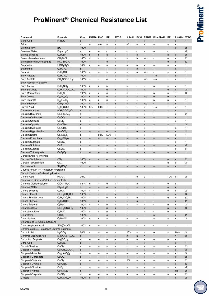
ProMinent® Chemical Resistance List
Boric Acid H3BO3 s + + + + + + + + + + 1Brine s + +/o + + +/o + + + + + 1Bromine (dry) Br2 100% - - - + - - - - - + 2Bromine Water Br2 + H2O s - + - + - - - n - n (2)Bromo Benzene C6H5Br 100% n n o + + o - - o + 2Bromochloro Methane CH2BrCl 100% - - - + + n +/o - o + 2Bromochlorotrifluoro Ethane HCClBrCF3 100% - - o + + + - + o + (3)Butanediol HOC4H8OH 10% n + + + + o + + + + 1Butanetriol C4H10O3 s + + + + + o + + + + 1Butanol C4H9OH 100% - + + + + o +/o - + + 1Butyl Acetate C7H13O2 100% - - + + + - - +/o + + 1Butyl Acetate CH3COOC4H9 100% - - o + + - +/o +/o - + 1Butyl Alcohol => ButanolButyl Amine C4H9NH2 100% n n n - + - - n + + 1Butyl Benzoate C6H5COOC4H9 100% - - o n + + + - o + 2Butyl Mercaptane C4H9SH 100% n n n + n + - n n n 3Butyl Oleate C22H42O2 100% n n n + + + +/o n n + 1Butyl Stearate C22H44O2 100% o n n + + + - n n + 1Butyraldehyde C3H7CHO 100% - n + n + - +/o - + + 1Butyric Acid C3H7COOH 100% 5% 20% + + + + + +/o + + 1Calcium Acetate (CH3COO)2Ca s + + + + + + + + + + 1Calcium Bisulphite Ca(HSO3)2 s + + + + + + + + + + (1)Calcium Carbonate CaCO3 s + + + + + + + + + + 1Calcium Chloride CaCl2 s + + + + - + + + + + 1Calcium Cyanide Ca(CN)2 s + + + + n + + + + n 3Calcium Hydroxide Ca(OH)2 s + + + + + + + + + + 1Calcium Hypochlorite Ca(OCl)2 s + + o + - o + + + + 2Calcium Nitrate Ca(NO3)2 s + 50% 50% + + + + + + + 1Calcium Phosphate Ca3(PO4)2 s + + + + + + + + + + 1Calcium Sulphate CaSO4 s + + + + + + + + + + 1Calcium Sulphide CaS s + + + + n + + + + + (2)Calcium Sulphite CaSO3 s + + + + + + + + + + (1)Calcium Thiosulphate CaS2O3 s + + + + - + + + + + 1Carbolic Acid => PhenoleCarbon Disulphide CS2 100% - - o + + + - - o + 2Carbon Tetrachloride CCl4 100% - - - + + + - - o + 3Carbonic Acid "H2CO3" s + + + + + + + + + + 1Caustic Potash => Potassium HydroxideCaustic Soda => Sodium HydroxideChloric Acid HClO3 20% + + - + - o o + 10% + 2Chlorinated Lime => Calcium HypochloriteChlorine Dioxide Solution ClO2 + H2O 0.5% o + o + 1) - o - - o +Chlorine Water Cl2 + H2O s + + o + - + + - o +Chloro Benzene C6H5Cl 100% - - + + + + - - o + 2Chloro Ethanol ClCH2CH2OH 100% - - + o + - o + + + 3Chloro Ethylbenzene C6H4ClC2H5 100% - - o n + o - - o + (2)Chloro Phenole C6H4OHCl 100% - n + + + n - - + + 2Chloro Toluene C7H8Cl 100% - - n + + + - - n + 2Chloroacetone ClCH2COCH3 100% - - n n + - + - n + 3Chlorobutadiene C4H5Cl 100% - - n n + + - - n + 1Chloroform CHCl3 100% - - o + + + - o - + 2Chlorohydrin C3H5OCl 100% - n + - + + o + + + 3Chloroprene => ChlorobutadieneChlorosulphonic Acid SO2(OH)Cl 100% - o - + - - - - - o 1Chrome-alum => Potassium Chrome SulphateChromic Acid H2CrO4 50% - +* o + 10% + - o + 10% 3Chromic-Sulphuric Acid K2CrO4+ H2SO4 s - +* - + n n n - - n 3Chromium Sulphate Cr2(SO4)3 s + + + + + + + + + + 1Citric Acid C6H8O7 s + + + + + + + + + + 1Cobalt Chloride CoCl2 s + + + + - + + + + + 2Copper-II-Acetate Cu(CH3COO)2 s + + + + + + + + + + 3Copper-II-Arsenite Cu3(AsO3)2 s + + + + + + + + + + 3Copper-II-Carbonate CuCO3 s + + + + + + + + + + 2Copper-II-Chloride CuCl2 s + + + + 1% + + + + + 2Copper-II-Cyanide Cu(CN)2 s + + + + + + + + + + (3)Copper-II-Fluoride CuF2 s + + + + + + + + + + (2)Copper-II-Nitrate Cu(NO3)2 s + + + + + + + + + +/o 2Copper-II-Sulphate CuSO4 s + + + + + + + + + + 2Cresols C6H4CH3OH 100% o o + + + + - - + + 2
Chemical Formula Conc PMMA PVC PP PVDF 1.4404 FKM EPDM PharMed® PE 2.4819 WPC
1.1.2019 3

ProMinent® Chemical Resistance List
Crotonaldehyde CH3C2H2CHO 100% n - + + + - + - + + 3Cubic Nitre => Sodium NitrateCumene => Isopropyl BenzeneCyclo Hexane C6H12 100% + - + + + + - - + o 1Cyclohexanole C6H11OH 100% o +/o + + + + - - + + 1Cyclohexanone C6H10O 100% - - + - + - +/o - + + 1Cyclohexyl Alcohol => CyclohexanolCyclohexylamine C6H11NH2 100% n n n n + - n n n + 2Decahydronaphthaline C10H18 100% - +/o o + n o - - o + 2Decaline => DecahydronaphthaleneDextrose => GlucoseDiacetonalcohol C6H12O2 100% - - + o + - + - + + 1Dibromoethane C2H4Br2 100% - - n + + + - - - + 3Dibutyl Ether C4H9OC4H9 100% - - + + + - o - + + 2Dibutyl Phthalate C16H22O4 100% - - + + + + +/o + o + 2Dibutylamine (C4H9)2NH 100% n n + + + - - n + + 1Dichloro Acetic Acid Cl2CHCOOH 100% - + + + + - + o + + 1Dichloro Benzene C6H4Cl2 100% - - o + + + - - o + 2Dichloro Butan C4H8Cl2 100% - - o + + + - - o + 3Dichloro Butene C4H6Cl2 100% - - o + + o - - o + 3Dichloro Ethane C2H4Cl2 100% - - o + + + - o - + 3Dichloro Ethylene C2H2Cl2 100% - - o + + o - o - + 2Dichloro Methane CH2Cl2 100% - - o o o + - o - + 2Dichloroisopropyl Ether (C3H6Cl)2O 100% - - o n + o o - o + (2)Dicyclohexylamine (C6H12)2NH 100% - - o n + - - - o + 2Diethyleneglycol C4H10O3 s + + + + + + + + + + 1Diethyleneglycolethyl Ether C8H18O3 100% n n + + + n +/o o + + 1Diethylether C2H5OC2H5 100% - - o + + - - o o + 1Diglycolic Acid C4H6O5 30% + + + + + + n +/o + + 3Dihexyl Phthalate C20H26O4 100% - - + + + - n + + + (1)Diisobutylketone C9H18O 100% - - + + + - + - + + 1Di-iso-nonyl Phthalate C26H42O4 100% - - + + + n n + + + 1Diisopropylketone C7H14O 100% - - + + + - + - + + 1Dimethyl Carbonate (CH3O)2CO 100% n n + + + + - n + + 1Dimethyl Ketone => AcetoneDimethyl Phthalate C10H10O4 100% - - + + + - +/o + + + 1Dimethylformamide HCON(CH3)2 100% - - + - + - + +/o + + 1Dimethylhydrazine H2NN(CH3)2 100% n n + n + - + n + + 3Dioctyl Phthalate C4H4(COOC8H17)2 100% - - + + + - +/o + + + 1Dioxane C4H8O2 100% - - o - + - +/o - + + 1Disodium Hydrogenphosphate Na2HPO4 s + + + + + + + + + + 1Disulfur Acid -- OleumDisulphur Dichloride S2Cl2 100% n n n + n + - - n nDMF => DimethylformamideEngine Oils 100% n +/o + + + + - - + + 2Epsom salts => Magnesium SulphateEthanol C2H5OH 100% - + + + + - + + + + 1Ethanol Amine HOC2H4NH2 100% o n + - + - +/o o + + 1Ethyl Acetate CH3COOC2H5 100% - - 35% + + - +/o +/o + + 1Ethyl Acrylate C2H3COOC2H5 100% - - + o + - +/o - + + 2Ethyl Benzene C6H5-C2H5 100% - - o + + o - - o + 1Ethyl Benzoate C6H5COOC2H5 100% n - + o + + - - + + 1Ethyl Bromide C2H5Br 100% - n + + n + - o + + 2Ethyl Chloroacetate ClCH2COOC2H5 100% - o + + + + - - + + 2Ethyl Chlorocarbonate ClCO2C2H5 100% n n n n n + - n n n (2)Ethyl Cyclopentane C5H4C2H5 100% + + + + + + - - + + (1)Ethylacetoacetate C6H10O3 100% n - + + + - +/o +/o + + 1Ethylacrylic Acid C4H7COOH 100% n n + + + n +/o n + + (1)Ethylene Diamine (CH2NH2)2 100% o o + - o - + n + o 2Ethylene Dibromide => DibromoethaneEthylene Dichloride => Dichloro EthaneEthylene Glycol => GlycolEthylenglycol Ethylether HOC2H4OC2H5 100% n n + + + n +/o o + + 1Ethylhexanol C8H16O 100% n +/o + + + + + - + + 2Fatty Acids R-COOH 100% + + + + + + o o + + 1Ferric Chloride FeCl3 s + + + + - + + + + +/o 1Ferric Nitrate Fe(NO3)3 s + + + + + + + + + + 1Ferric Phosphate FePO4 s + + + + + + + + + + 1Ferric Sulphate Fe2(SO4)3 s + + + + o + + + + + 1
Chemical Formula Conc PMMA PVC PP PVDF 1.4404 FKM EPDM PharMed® PE 2.4819 WPC
4 1.1.2019

ProMinent® Chemical Resistance List
Ferrous Chloride FeCl2 s + + + + - + + + + +/o 1Ferrous Sulphate FeSO4 s + + + + + + + + + + 1Fixing Salt => Sodium ThiosulphateFluoro Benzene C6H5F 100% - - + + + o - - o + 2Fluoroboric Acid HBF4 35% + + + + o + + - + + 1Fluorosilicic Acid H2SiF6 100% + 30% 30% + o + + o 40% +/o 2Formaldehyde CH2O 40% + + + + + - +/o - + + 2Formalin => FormaldehydeFormamide HCONH2 100% + - + + + + + n + + 1Formic Acid HCOOH s - +/o + + + - - +/o + + 1Furane C4H4O 100% - - + - + - n - + + 3Furane Aldehyde C5H5O2 100% n n n o + - +/o - n n 2Furfuryl Alcohol OC4H3CH2OH 100% - - + o + n +/o - + + 1Gallic Acid C6H2(OH)3COOH 5% + + + + + + +/o + + + 1Gasoline 100% - - + + + + - - + + 2Glauber´s Salt => Sodium SulphateGlucose C6H12O6 s + + + + + + + + + + 1Glycerol C3H5(OH)3 100% + + + + + + + + + + 1Glycerol Triacetate C3H5(CH3COO)3 100% n n + + + - + n + + 1Glycine NH2CH2COOH 10% + + + + + + + + + + 1Glycol C2H4(OH)2 100% + + + + + + + + + + 1Glycolic Acid CH2OHCOOH 70% + 37% + + + + + +/o + + 1Gypsum => Calcium SulphateHeptane C7H16 100% + + + + + + - - + + 1Hexachloroplatinic Acid H2PtCl6 s n + + + - n + n + -Hexanal C5H11CHO 100% n n + + + - +/o - + + 1Hexane C6H14 100% + + + + + + - - + + 1Hexanol C6H13OH 100% - - + + + n + o + + 1Hexantriol C6H9(OH)3 100% n n + + + + + n + + 1Hexene C6H12 100% n + + + + + - - + + 1Hydrazine Hydrate N2H4 * H2O s + + + + + n + o + + 3Hydrobromic Acid HBr 50% + + + + - - + - + o 1Hydrochloric Acid HCl 38% 32% + * + + - + o o + o 1Hydrofluoric Acid HF 80% - 40%* 40%** + - + o - 40% +/o 1Hydrogen Cyanide HCN s + + + + + + + + + + 3Hydrogen Peroxide H2O2 90% 40% 40%* 30% + + 30% 30% + + + 1Hydroiodic Acid HI s + + + + - - n - + n 1Hydroquinone C6H4(OH)2 s o + + + + + - +/o + + 2Hydroxylamine Sulphate (NH2OH)2 * H2SO4 10% + + + + + + + + + + 2Hypochlorous Acid HOCl s + + o + - + +/o + o + (1)Iodine I2 s o - + + - + +/o + o +/oIron Vitriol => Ferrous SulphateIsobutanol => Isobutyl AlcoholIsobutyl Alcohol C2H5CH(OH)CH3 100% - + + + + + + o + + 1Isopropanol => Isopropyl Alcohol Isopropyl Acetate CH3COOCH(CH3)2 100% - - + + + - +/o +/o + + 1Isopropyl Alcohol (CH3)2CHOH 100% - +/o + + + + + o + + 1Isopropyl Benzene C6H5CH(CH3)2 100% - - o + + + - - o + 1Isopropyl Chloride CH3CHClCH3 80% - - o + + + - o o +/o 2Isopropyl Ether C6H14O 100% - - o + + - - o o + 1Kitchen Salt => Sodium ChlorideLactic Acid C3H6O3 100% - + + + +/o + 10% +/o + + 1Lead Acetate Pb(CH3COO)2 s + + + + + + + + + + 2Lead Nitrate Pb(NO3)2 50% + + + + + + + + + + 2Lead Sugar => Lead AcetateLead Sulphate PbSO4 s + + + + + + + + + + (2)Lead Tetraethyl Pb(C2H5)4 100% + + + + + + - n + + 3Lime Milk => Calcium HydroxideLiquid Ammonia => Ammonium HydroxideLithium Bromide LiBr s + + + + + + + + + + 1Lithium Chloride LiCl s + + + + - + + + + n 1Lunar Caustic => Silver NitrateMagnesium Carbonate MgCO3 s + + + + + + + + + +/o 1Magnesium Chloride MgCl2 s + + + + o + + + + + 1Magnesium Hydroxide Mg(OH)2 s + + + + + + + + + + 1Magnesium Nitrate Mg(NO3)2 s + + + + + + + + + + 1Magnesium Sulphate MgSO4 s + + + + + + + + + +/o 1Maleic Acid C4H4O4 s + + + + + + + o + + 1Malic Acid C4H6O5 s + + + + + + + + + + 1
Chemical Formula Conc PMMA PVC PP PVDF 1.4404 FKM EPDM PharMed® PE 2.4819 WPC
1.1.2019 5

ProMinent® Chemical Resistance List
Manganese-II-Chloride MnCl2 s + + + + - + + + + + 1Manganese-II-Sulphate MnSO4 s + + + + + + + + + + 1MEK => Methyl Ethyl KetoneMercury Hg 100% + + + + + + + + + + 3Mercury-II-Chloride HgCl2 s + + + + - + + + + + 3Mercury-II-Cyanide Hg(CN)2 s + + + + + + + + + + 3Mercury-II-Nitrate Hg(NO3)2 s + + + + + + + + + + 3Mesityl Oxide C6H10O 100% - - n n + - +/o - n + 1Methacrylic Acid C3H5COOH 100% n n + + + o +/o +/o + + 1Methanol CH3OH 100% - - + + + o + +/o + + 1Methoxybutanol CH3O(CH2)4OH 100% - - + + + + o o + + (1)Methyl Acetate CH3COOCH3 60% - - + + + - +/o +/o + + 2Methyl Acrylate C2H3COOCH3 100% - - + + + - +/o o + + 2Methyl Benzoate C6H5COOCH3 100% - - + o + + - - + + 2Methyl Catechol C6H3(OH)2CH3 s + + + + + + - +o + + (1)Methyl Cellulose s + + + + + + + + + + 1Methyl Chloroacetate ClCH2COOCH3 100% - o + + + o - - + + 2Methyl Cyclopentane C5H9CH3 100% + + + + + + - - + + (1)Methyl Dichloroacetate Cl2CHCOOCH3 100% - - + n + - n - + + 2Methyl Ethyl Ketone CH3COC2H5 100% - - + - + - + - + + 1Methyl Glycol C3H8O2 100% + + + + + - +/o + + + 1Methyl Isobutyl Ketone CH3COC4H9 100% - - + - + - o - + + 1Methyl Isopropyl Ketone CH3COC3H7 100% - - + - + - +/o - + + 1Methyl Methacrylate C3H5COOCH3 100% - - + + + - - - + + 1Methyl Oleate C17H33COOCH3 100% n n + + + + +/o n + + 1Methyl Salicylate HOC6H4COOCH3 100% - - + + + n +/o - + + 1Methylacetyl Acetate C5H8O3 100% - - + + + - +/o o + + 2Methylamine CH3NH2 32% + o + o + - + + + + 2Methylene Chloride => Dichloro MethaneMirabilit => Sodium SulphateMorpholine C4H9ON 100% - - + - + n n - + + 2Muriatic Acid => Hydrochloric AcidNatron => Sodium BicarbonateNickel-II-Acetate (CH3COO)2Ni s + + + + + - + + + + (2)Nickel-II-Chloride NiCl2 s + + + + - + + + + + 2Nickel-II-Nitrate Ni(NO3)2 s + + + + + + + + + +/o 2Nickel-II-Sulphate NiSO4 s + + + + + + + + + +/o 2Nitrate of Lime => Calcium NitrateNitric Acid HNO3 99% 10% 10%* 50% 65% 50% 65% 10% 35% 50% 65% 1Nitro Methane CH3NO2 100% - - + o + - +/o - + + 2Nitro Propane (CH3)2CHNO2 100% - - + n + - +/o - + + 2Nitro Toluene C6H4NO2CH3 100% - - + + + o - - + + 2Octane C8H18 100% o + + + + + - - + + 1Octanol C8H17OH 100% - - + + + + + - + + 1Octyl Cresol C15H24O 100% - - + + + o n - + + (1)Oil => Engine OilsOleum H2SO4 + SO3 s n - - - + + - + - + 2Orthophosphoric Acid => Phosphoric AcidOxalic Acid (COOH)2 s + + + + 10% + + +/o + +/o 1Pentane C5H12 100% + + + + + + - - + + 1Pentanol => Amyl AlcoholPerchloric Acid HClO4 70% n 10% 10% + - + +/o + + n 1Perchloroethylene => Tetrachloro EthylenePerhydrol => Hydrogen PeroxidePetroleum Ether CnH2n+2 100% + +/o + + + + - - + + 1Phenole C6H5OH 100% - - + + + + - + + + 2Phenyl Ethyl Ether C6H5OC2H5 100% - - + n + - - - + + 2Phenyl Hydrazine C6H5NHNH2 100% - - o + + o - - o + 2Phosphoric Acid H3PO4 85% 50% + + + + + + + + + 1Phosphorous Oxychloride POCl3 100% - - + + n + + n + + 1Phosphorous Trichloride PCl3 100% - - + + + o + +/o + + 1Phthalic Acid C6H4(COOH)2 s + + + + + + + + + + 1Picric Acid C6H2(NO3)3OH s + + + + + + + - + + 2Piperidine C5H11N 100% - - n n + - - - n + 2Potash Alum => Potassium Aluminium SulphatePotassium Acetate CH3COOK s + + + + + + + + + + 1Potassium Aluminium Sulphate KAl(SO4)2 s + + + + + + + + + + 1Potassium Bicarbonate KHCO3 40% + + + + + + + + + +/o 1Potassium Bifluoride KHF2 s n + + + + + + + + + 1
Chemical Formula Conc PMMA PVC PP PVDF 1.4404 FKM EPDM PharMed® PE 2.4819 WPC
6 1.1.2019

ProMinent® Chemical Resistance List
Potassium Bisulphate KHSO4 5% + + + + + + + + + + 1Potassium Bitartrate KC4H5O6 s + + + + + + + + + + 1Potassium Borate KBO2 s + + + + + + + + + + (1)Potassium Bromate KBrO3 s + + + + + + + + + + 2Potassium Bromide KBr s + + + + 10% + + + + 0.1 1Potassium Carbonate K2CO3 s + + + + + + + 55% + + 1Potassium Chlorate KClO3 s + + + + + + + + + + 2Potassium Chloride KCl s + + + + - + + + + +/o 1Potassium Chromate K2CrO4 10% + + + + + + + + + + 3Potassium Chrome Sulphate KCr(SO4)2 s + + + + + + + + + + 1Potassium Cyanate KOCN s + + + + + + + + + + 2Potassium Cyanide KCN s + + + + 5% + + + + 5% 3Potassium Cyanoferrate II K4Fe(CN)6 s + + + + + + + + + + 1Potassium Cyanoferrate III K3Fe(CN)6 s + + + + + + + + + + 1Potassium Dichromate K2Cr2O7 s + + + + 25% + + + + 10% 3Potassium Fluoride KF s + + + + + + + + + + 1Potassium Hydroxyde KOH 50% + + + + (25 °C) + - + 10% + + 1Potassium Iodide KI s + + + + + + + + + + 1Potassium Nitrate KNO3 s + + + + + + + + + + 1Potassium Perchlorate KClO4 s + + + + n + + + + + 1Potassium Permanganate KMnO4 s + + + + + + + 6% + + 2Potassium Persulphate K2S2O8 s + + + + + + + + + + 1Potassium Phosphate KH2PO4 s + + + + + + + + + + 1Potassium Pyrochromate => Potassium DichromatePotassium Sulphate K2SO4 s + + + + + + + + + + 1Potassium Sulphite K2SO3 s + + + + + + + + + + 1Propionic Acid C2H5COOH 100% o + + + + + + +/o + + 1Propionitrile CH3CH2CN 100% n n + + + + - - + + 2Propyl Acetate CH3COOC3H7 100% - - + + + - +/o - + + 1Propylene Glycol CH3CHOHCH2OH 100% + + + + + + + + + + 1Prussic Acid => Hydrogen CyanidePyridine C5H5N 100% - - o - + - - o + + 2Pyrrole C4H4NH 100% n n + n + - - - + + 2Roman Vitriol => Copper SulphateSalicylic Acid HOC6H4COOH s + + + + + + + + + +/o 1Salmiac => Ammonium ChlorideSaltpeter => Potassium NitrateSilic Acid SiO2 * x H2O s + + + + + + + + + + 1Silver Bromide AgBr s + + + + +/o + + + + + 1Silver Chloride AgCl s + + + + - + + + + +/o 1Silver Nitrate AgNO3 s + + + + + + + + + +/o 3Slaked Lime => Calcium HydroxideSoda => Sodium CarbonateSodium Acetate NaCH3COO s + + + + + + + + + + 1Sodium Benzoate C6H5COONa s + + + + + + + + + + 1Sodium Bicarbonate NaHCO3 s + + + + + + + + + + 1Sodium Bisulphate NaHSO4 s + + + + + + + + + + 1Sodium Bisulphite NaHSO3 s + + + + + + + + + + 1Sodium Borate NaBO2 s + + + + + + + + + + 1Sodium Bromate NaBrO3 s + + + + + + + + + + 3Sodium Bromide NaBr s + + + + + + + + + + 1Sodium Carbonate Na2CO3 s + + + + +/o + + + + + 1Sodium Chlorate NaClO3 s + + + + + + + + + + 2Sodium Chloride NaCl s + + + + - + + + + + 1Sodium Chlorite NaClO2 24% + + + + 10% + + + + 10% 2Sodium Chromate Na2CrO4 s + + + + + + + + + + 3Sodium Cyanide NaCN s + + + + + + + + + + 3Sodium Dichromate Na2Cr2O7 s + + + + + + + + + + 3Sodium Dithionite Na2S2O4 s + 10% 10% + + n n + 10% +/o 1Sodium Fluoride NaF s + + + + 10% + + + + + 1Sodium Hydrogen Sulphate => Sodium BisulphateSodium Hydroxide NaOH 50% + + + + (60%/
25 °C)+ - + 30% + + 1
Sodium Hypochlorite NaOCl + NaCl 12% + + o + - + + + o > 10% 2Sodium Iodide NaI s + + + + + + + + + + 1Sodium Metaphosphate (NaPO3)n s + + + + + + + + + + 1Sodium Nitrate NaNO3 s + + + + + + + + + + 1Sodium Nitrite NaNO2 s + + + + + + + + + + 2Sodium Oxalate Na2C2O4 s + + + + + + + + + + 1
Chemical Formula Conc PMMA PVC PP PVDF 1.4404 FKM EPDM PharMed® PE 2.4819 WPC
1.1.2019 7

ProMinent® Chemical Resistance List
Sodium Perborate NaBO2*H2O2 s + +/o + + + + + + + +/o 1Sodium Perchlorate NaClO4 s + + + + 10% + + + + 10% 1Sodium Peroxide Na2O2 s + + + + + + + n - + 1Sodium Persulphate Na2S2O8 s n + + + + + + + + + 1Sodium Pyrosulphite Na2S2O5 s + + + + + n n + + + 1Sodium Salicylate C6H4(OH)COONa s + +/o + + + + + + + + 1Sodium Silicate Na2SiO3 s + + + + + + + + + + 1Sodium Sulphate Na2SO4 s + + + + + + + + + + 1Sodium Sulphide Na2S s + + + + + + + + + + 2Sodium Sulphite Na2SO3 s + + + + 50% + + + + 50% 1Sodium Tetraborate Na2B4O7 * 10 H2O s + + + + + + + + + + 1Sodium Thiosulphate Na2S2O3 s + + + + 25% + + + + 25% 1Sodium Tripolyphosphate Na5P3O10 s + + + + + +/o + + + + 1Starch (C6H10O5)n s + + + + + + n + + + 1Starch Gum s + + + + + + + + + + 1Styrene C6H5CHCH2 100% - - o + + o - - o + 2Sublimate => Mercury-II-ChlorideSuccinic Acid C4H6O4 s + + + + + + + + + + 1Sugar Syrup s + + + + + + + + + + 1Sulphur Chloride => Disulphur DichlorideSulphuric Acid H2SO4 98% 30% 50% 85% + 20% + + 30% 80% + 1Sulphuric Acid, fuming --> OleumSulphurous Acid H2SO3 s + + + + 10% + + + + + (1)Sulphuryl Chloride SO2Cl2 100% - - - o n + o - - n 1Tannic Acid C76H52O46 50% + + + + + + + + + + 1Tartaric Acid C4H6O6 s 50% + + + + + +/o + + + 1Tetrachloro Ethane C2H2Cl4 100% - - o + + o - o o + 3Tetrachloro Ethylene C2Cl4 100% - - o + + o - o o + 3Tetrachloromethane => Carbon TetrachlorideTetrahydro Furane C4H8O 100% - - o - + - - - o + 1Tetrahydro Naphthalene C10H12 100% - - - + + + - - o + 3Tetralin => Tetrahydro NaphthaleneTHF => TetrahydrofuraneThionyl Chloride SOCl2 100% - - - + n + + + - n 1Thiophene C4H4S 100% n - o n + - - - o + 3Tin-II-Chloride SnCl2 s + o + + - + + + + +/o 1Tin-II-Sulphate SnSO4 s n + + + + + + + + +/o (1)Tin-IV-Chloride SnCl4 s n + + + - + + + + + 1Titanium Tetrachloride TiCl4 100% n n n + n o - n n n 1Toluene C6H5CH3 100% - - o + + o - - o + 2Toluene Diisocyanate C7H3(NCO)2 100% n n + + + - +/o n + + 2Tributyl Phosphate (C4H9)3PO4 100% n - + + + - + + + + 1Trichloro Ethane CCl3CH3 100% - - o + + + - o o + 3Trichloro Ethylene C2HCl3 100% - - o + +/o o - o o + 3Trichloro Methane => ChloroformTrichloroacetaldehyde Hydrate CCl3CH(OH)2 s - - o - + o o n + + 2Trichloroacetic Acid CCl3COOH 50% - + + + - - o +/o + + 1Tricresyl Phosphate (C7H7)3PO4 90% - - + n + o + + + + 2Triethanol Amine N(C2H4OH)3 100% + o + n + - +/o o + + 1Trilene => Trichloro EthaneTrioctyl Phosphate (C8H17)3PO4 100% n - + + + o + + + + 2Trisodium Phosphate Na3PO4 s + + + + + + + + + + 1Urea CO(NH2)2 s + +/o + + + + + 20% + + 1Vinyl Acetate CH2=CHOOCCH3 100% - - + + + n n +/o + + 2Water Glass => Sodium SilicateXylene C6H4(CH3)2 100% - - - + + o - - o + 2Zinc Acetate (CH3COO)2Zn s + + + + + - + + + + 1Zinc Chloride ZnCl2 s + + + + - + + + + n 1Zinc Sulphate ZnSO4 s + + + + + + + + + +/o 1
Chemical Formula Conc PMMA PVC PP PVDF 1.4404 FKM EPDM PharMed® PE 2.4819 WPC
1) Chlorine dioxide is capable of penetrating through PVDF without destroying it. This can lead to damage to PVDF-coated parts.
8 1.1.2019

ProMinent® Chemical Resistance List
This data applies to standard conditions (20 °C, 1013 mbar).
The data is taken from relevant manufacturers' literature and supplemented by our own tests and experience. As the resistance of a material also depends on other factors, especially pressure and operating conditions etc, this list should merely be regarded as an initial guide and does not claim to offer any guarantees. Take into consideration the fact that conventional dosing agents are largely compounds, the corrosiveness of which cannot simply be calculated by adding together the corrosiveness of each individual component. In cases such as these the material compatibility data produced by the chemical manufacturer must be read as a matter of priority when selecting a material. Safety data sheets do not provide this information and cannot therefore replace application-specific documentation.
Overview of the Resistance of Soft PVC Hoses (Guttasyn®) to the Most Common Chemicals
+ = resistanto = conditionally resistant- = not resistant
Corrosive agent Concentration in % EvaluationAcetone all -Acetylene tetrabromide 100 -Alums of all kinds, aqueous all +Aluminium salts, aqueous all +Ammonium, aqueous 15 -Ammonium, aqueous saturated -Ammonium salts all +Aniline 100 -Benzene 100 -Bisulphite, aqueous 40 +Borax solution all +Boric acid, aqueous 10 +Bromine, vaporous and liquid -Hydrogen bromide 10 +Butanol 100 +Butyric acid, aqueous 20 +Butyric acid, aqueous conc. -Butyl acetate 100 -Calcium chloride, aqueous all +Chlorinated hydrocarbons all -Chrome-alum, aqueous all +Chromic acid, aqueous 50 -Dextrin, aqueous saturated +Diesel oils, compressed oils 100 oDiethyl ether 100 -Fertilizing manure salt, aqueous all +Ferric chloride, aqueous all +Glacial acetic acid 100 -Acetic ester 100 -Acetic acid, aqueous 10 +Acetic acid 50 oAcetic acid (wine vinegar) oAcetic acid anhydride 100 -Ethanol 96 -Ethyl acetate 100 -Ethylene glycol 30 +Formaldehyde, aqueous 30 oDifluorodichloromethane 100 -Glycerol 100 -Glucose, aqueous saturated +Halogens all -Urea, aqueous all +Caustic potash 15 +Potassium bichromate, aqueous saturated +Potassium persulphate, aqueous saturated +
1.1.2019 9

ProMinent® Chemical Resistance List
Creosote -Sodium chloride, aqueous all +Carbonic acid all +Copper sulphate, aqueous all +Magnesium salts, aqueous all +Methyl alcohol 100 +Methylene chloride 100 -Sodium hypochlorite 15 +Sodium salts => sodium chlorideSodium hydroxide aqueous +Oils => fats, diesel oil, Lubricating oil and similarPerchloric acid all oPhenol, aqueous all oPhosphoric acid, aqueous 100 -Nitric acid, aqueous 25 +Hydrochloric acid 15 +Sulphur dioxide, gaseous all +Carbon disulphide 100 -Sulphuric acid 30 +Hydrogen sulphide, gaseous 100 -Silver nitrate 10 +Tetrachloromethane 100 -Ink +Toluene 100 -Trichloroethylene 100 -Hydrogen peroxide to 10 +Xylene 100 -Zinc salts all +
Corrosive agent Concentration in % Evaluation
10 1.1.2019


ProducYour digWherev
Groundbreak
Our product
www.promin
Do you needThen we wou
www.promin
t catalogue 2019 ital reference source.
er you want. Whenever you want.
ing diversity: ProMinent 2019.
catalogue is available in three individual volumes.
ent.com/en/product-catalogue
Metering Technology
Measuring, Control and Sensor Technology
Water Treatment and Disinfection
an overview of our entire product range? ld recommend our product overview.
ent.com/en/productoverview