
Metallic tube connections for fluid power and general use...
28
Reference number ISO 19879:2010(E) © ISO 2010 INTERNATIONAL STANDARD ISO 19879 Second edition 2010-09-15 Metallic tube connections for fluid power and general use — Test methods for hydraulic fluid power connections Raccords de tubes métalliques pour transmissions hydrauliques et pneumatiques et applications générales — Méthodes d'essai pour raccords pour transmissions hydrauliques Licensed to:Schwartz, Carrie Tatman Ms Downloaded:2015-08-03 Single user licence only, copying and networking prohibited
Transcript of Metallic tube connections for fluid power and general use...
Reference numberISO 19879:2010(E)
© ISO 2010
INTERNATIONAL STANDARD
ISO19879
Second edition2010-09-15
Metallic tube connections for fluid power and general use — Test methods for hydraulic fluid power connections
Raccords de tubes métalliques pour transmissions hydrauliques et pneumatiques et applications générales — Méthodes d'essai pour raccords pour transmissions hydrauliques
Licensed to:Schwartz, Carrie Tatman MsDownloaded:2015-08-03Single user licence only, copying and networking prohibited

ISO 19879:2010(E)
PDF disclaimer This PDF file may contain embedded typefaces. In accordance with Adobe's licensing policy, this file may be printed or viewed but shall not be edited unless the typefaces which are embedded are licensed to and installed on the computer performing the editing. In downloading this file, parties accept therein the responsibility of not infringing Adobe's licensing policy. The ISO Central Secretariat accepts no liability in this area.
Adobe is a trademark of Adobe Systems Incorporated.
Details of the software products used to create this PDF file can be found in the General Info relative to the file; the PDF-creation parameters were optimized for printing. Every care has been taken to ensure that the file is suitable for use by ISO member bodies. In the unlikely event that a problem relating to it is found, please inform the Central Secretariat at the address given below.
COPYRIGHT PROTECTED DOCUMENT © ISO 2010 All rights reserved. Unless otherwise specified, no part of this publication may be reproduced or utilized in any form or by any means, electronic or mechanical, including photocopying and microfilm, without permission in writing from either ISO at the address below or ISO's member body in the country of the requester.
ISO copyright office Case postale 56 • CH-1211 Geneva 20 Tel. + 41 22 749 01 11 Fax + 41 22 749 09 47 E-mail [email protected] Web www.iso.org
Published in Switzerland
ii © ISO 2010 – All rights reserved
Licensed to:Schwartz, Carrie Tatman MsDownloaded:2015-08-03Single user licence only, copying and networking prohibited

ISO 19879:2010(E)
© ISO 2010 – All rights reserved iii
Contents Page
Foreword ............................................................................................................................................................iv Introduction.........................................................................................................................................................v 1 Scope ......................................................................................................................................................1 2 Normative references............................................................................................................................1 3 Terms and definitions ...........................................................................................................................2 4 General requirements ...........................................................................................................................2 5 Repeated assembly test........................................................................................................................6 6 Leakage test ...........................................................................................................................................6 7 Proof test ................................................................................................................................................7 8 Burst test ................................................................................................................................................9 9 Cyclic endurance test ...........................................................................................................................9 10 Vacuum test .........................................................................................................................................10 11 Overtightening test..............................................................................................................................11 12 Vibration test........................................................................................................................................11 13 Cyclic endurance (impulse) test with vibration................................................................................14 14 Identification statement (Reference to this International Standard)...................................................15 Annex A (normative) Test data form...............................................................................................................16 Bibliography......................................................................................................................................................19
Licensed to:Schwartz, Carrie Tatman MsDownloaded:2015-08-03Single user licence only, copying and networking prohibited

ISO 19879:2010(E)
iv © ISO 2010 – All rights reserved
Foreword
ISO (the International Organization for Standardization) is a worldwide federation of national standards bodies (ISO member bodies). The work of preparing International Standards is normally carried out through ISO technical committees. Each member body interested in a subject for which a technical committee has been established has the right to be represented on that committee. International organizations, governmental and non-governmental, in liaison with ISO, also take part in the work. ISO collaborates closely with the International Electrotechnical Commission (IEC) on all matters of electrotechnical standardization.
International Standards are drafted in accordance with the rules given in the ISO/IEC Directives, Part 2.
The main task of technical committees is to prepare International Standards. Draft International Standards adopted by the technical committees are circulated to the member bodies for voting. Publication as an International Standard requires approval by at least 75 % of the member bodies casting a vote.
Attention is drawn to the possibility that some of the elements of this document may be the subject of patent rights. ISO shall not be held responsible for identifying any or all such patent rights.
ISO 19879 was prepared by Technical Committee ISO/TC 131, Fluid power systems, Subcommittee SC 4, Connectors and similar products and components.
This second edition of ISO 19879 cancels and replaces the first edition (ISO 19879:2005) of which it constitutes a minor revision, with minor changes to 10.1, 10.2 (Table 7) and 12.2.2. (It also incorporates the Technical Corrigendum ISO 19879:2005/Cor. 1:2007.)
Licensed to:Schwartz, Carrie Tatman MsDownloaded:2015-08-03Single user licence only, copying and networking prohibited

ISO 19879:2010(E)
© ISO 2010 – All rights reserved v
Introduction
In hydraulic fluid power systems, power is transmitted and controlled through a liquid under pressure within an enclosed circuit. It is required that components be designed to meet these requirements under varying conditions. Testing of components to meet performance requirements provides a basis of assurance for determining design application and for checking component compliance with the stated requirements.
Licensed to:Schwartz, Carrie Tatman MsDownloaded:2015-08-03Single user licence only, copying and networking prohibited

Licensed to:Schwartz, Carrie Tatman MsDownloaded:2015-08-03Single user licence only, copying and networking prohibited
INTERNATIONAL STANDARD ISO 19879:2010(E)
© ISO 2010 – All rights reserved 1
Metallic tube connections for fluid power and general use — Test methods for hydraulic fluid power connections
WARNING — Some of the tests described in this International Standard are considered hazardous. It is, therefore, essential that, in conducting these tests, all appropriate safety precautions be strictly adhered to. Attention is drawn to the danger of burst, fine jets (which can penetrate the skin) and energy release of expanding gases. To reduce the hazard of energy release, bleed air out of test specimens prior to pressure testing. Tests shall be set up and performed by properly trained personnel.
1 Scope
This International Standard specifies uniform methods for the testing and performance evaluation of metallic tube connections, stud ends for ports and flange connections for use in hydraulic fluid power applications. This International Standard does not apply to the testing of hydraulic quick-action couplings, which is covered by ISO 7241-2.
Tests outlined in this International Standard are independent of each other and document the method to follow for each test. See the appropriate component International Standard for which tests to conduct and for performance criteria.
For qualification of the connector, the minimum number of samples specified in this International Standard is tested, unless otherwise specified in the relevant connector standard or as agreed upon by the manufacturer and the user.
2 Normative references
The following referenced documents are indispensable for the application of this document. For dated references, only the edition cited applies. For undated references, the latest edition of the referenced document (including any amendments) applies.
ISO 48, Rubber, vulcanized or thermoplastic — Determination of hardness (hardness between 10 IRHD and 100 IRHD)
ISO 3448, Industrial liquid lubricants — ISO viscosity classification
ISO 3601-3, Fluid power systems — O-rings — Part 3: Quality acceptance criteria
ISO 5598, Fluid power systems and components — Vocabulary
ISO 6508 (all parts), Metallic materials — Rockwell hardness test
ISO 6605, Hydraulic fluid power — Hoses and hose assemblies — Test methods
ISO 6743-4, Lubricants, industrial oils and related products (class L) — Classification — Part 4: Family H (Hydraulic systems)
Licensed to:Schwartz, Carrie Tatman MsDownloaded:2015-08-03Single user licence only, copying and networking prohibited

ISO 19879:2010(E)
2 © ISO 2010 – All rights reserved
3 Terms and definitions
For the purposes of this document, the terms and definitions given in ISO 5598 apply.
4 General requirements
4.1 Test assemblies
All components tested shall be in the final form, including annealed nuts, as required for brazed components. Unless otherwise specified in the respective connector standard, Type 1 test assemblies shall be as shown in Figure 1 for tube connections (for repeated assembly, leakage, proof, burst and cyclic endurance tests), and Type 2 test assemblies shall be as shown in Figure 2 for male stud ends (for leakage, proof and, if specified, burst and cyclic endurance tests). Alternatively, in order to test the connector to its full capability, use of the metallic tube may be omitted for burst and cyclic endurance tests, and different configurations with similar capability may be combined in a test assembly Type 3, as shown in Figure 3. Type 4 test assemblies for flange connectors shall be as shown in Figure 4. Test assemblies shall conform to the relevant requirements given in Table 1.
Table 1 — Requirements for test assemblies
Part code Part name Description and further information
A Straight stud connector The type of stud end, connector end and sealing method is optional but shall be recorded in the test report.
B Metallic tube The required tube wall thickness shall be selected according to the working pressure rating of the respective connector. The length of the tube shall be five times the tube outside diameter plus 50 mm.
C Shaped connector, with swivel, if applicable –––
D Blanking end (cap or plug) –––
E Shaped connector with adjustable stud end –––
F Flange connector –––
G Sealing e.g. O-ring.
Licensed to:Schwartz, Carrie Tatman MsDownloaded:2015-08-03Single user licence only, copying and networking prohibited

ISO 19879:2010(E)
© ISO 2010 – All rights reserved 3
Key 1 swivel nut
A straight stud connector B metallic tube C shaped connector D blanking end (cap or plug) G sealing, e.g. O-ring
a L = 5 × the tube OD (in millimetres) + 50 mm.
Figure 1 — Test assembly for tube connection — Type 1
a) Non-adjustable stud end connection b) Adjustable stud end connection, with shaped connector, if applicable
Key A straight stud connector D blanking end (cap or plug) E shaped connector with adjustable stud end G sealing, e.g. O-ring
Figure 2 — Test assembly for stud end — Type 2
Licensed to:Schwartz, Carrie Tatman MsDownloaded:2015-08-03Single user licence only, copying and networking prohibited

ISO 19879:2010(E)
4 © ISO 2010 – All rights reserved
Key 1 swivel nut
C shaped connector with swivel D blanking end (cap or plug) E shaped connector with adjustable stud end G sealing, e.g. O-ring
Figure 3 — Alternate connector capability test assembly without tube — Type 3
Key 1 O-ring seal 5 test adapter 2 split-flange clamp F flange connector 3 screw 4 washer
a This end capped or plugged.
Figure 4 — Test assembly for flange connectors — Type 4
Licensed to:Schwartz, Carrie Tatman MsDownloaded:2015-08-03Single user licence only, copying and networking prohibited

ISO 19879:2010(E)
© ISO 2010 – All rights reserved 5
4.2 Test equipment
4.2.1 Test block
Test blocks shall be unplated and have a hardness between 35 HRC and 45 HRC in accordance with ISO 6508. For a test block with multiple ports, the distance between the centrelines of test ports shall be a minimum of 1,5 times the port diameter. The distance between the port centreline and the edge of the test block shall be a minimum of 1 times the port diameter.
4.2.2 Test seals
For all tests, except for the overtightening test and unless otherwise specified, seals shall be nitrile (NBR) rubber with a hardness of (90 ± 5) IHRD when measured in accordance with ISO 48. Seals shall conform to their respective dimensional requirements, and O-rings shall meet or exceed the quality requirements for grade N (general purpose) of ISO 3601-3, if applicable.
4.3 Procedure
4.3.1 Thread lubrication
For all tests, on connectors made of carbon steel and for testing only, threads and contact surfaces shall be lubricated prior to application of torque using a hydraulic fluid with a viscosity of ISO VG 32 in accordance with ISO 3448. For connectors made of materials other than carbon steel, the manufacturer's recommendation for thread lubrication shall be followed.
4.3.2 Torque
For all tests, except the repeated assembly and overtightening tests, tube connections and stud ends shall be tested at the required minimum torques or number of hex flats or turns from finger-tight position given in the respective connector standard, if specified. Otherwise, they shall be tested at the minimum torque values or number of hex flats or turns from finger-tight position supplied by the manufacturer. For test assembly, type 2 and type 3 adjustable stud torques shall be applied after being backed out one full turn from finger-tight, in order to test correctly the worst possible actual assembly conditions.
4.3.3 Temperature
For all tests, the temperature of the hydraulic fluid shall be between 15 °C and 80 °C, unless otherwise specified in the respective connector standard.
4.4 Test report
Test results and test conditions shall be reported on the test data form given in Annex A.
NOTE ISO/TR 11340 provides a method of reporting leakage.
Licensed to:Schwartz, Carrie Tatman MsDownloaded:2015-08-03Single user licence only, copying and networking prohibited
ISO 19879:2010(E)
6 © ISO 2010 – All rights reserved
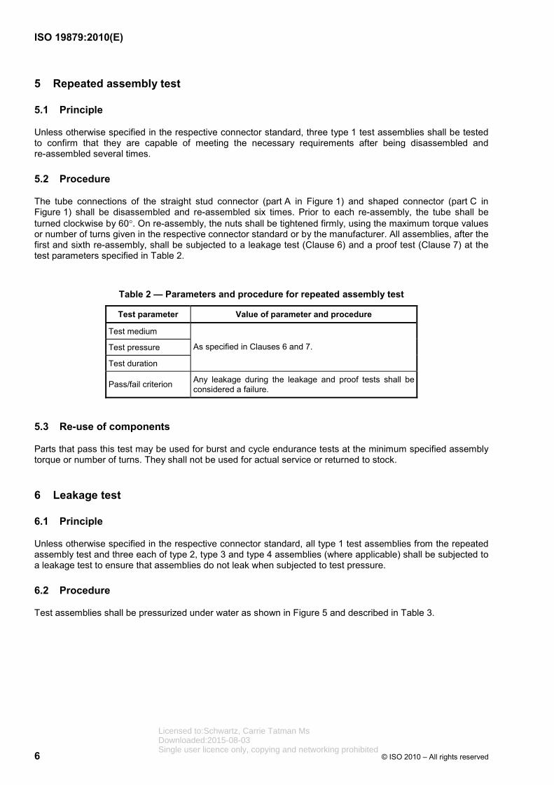
5 Repeated assembly test
5.1 Principle
Unless otherwise specified in the respective connector standard, three type 1 test assemblies shall be tested to confirm that they are capable of meeting the necessary requirements after being disassembled and re-assembled several times.
5.2 Procedure
The tube connections of the straight stud connector (part A in Figure 1) and shaped connector (part C in Figure 1) shall be disassembled and re-assembled six times. Prior to each re-assembly, the tube shall be turned clockwise by 60°. On re-assembly, the nuts shall be tightened firmly, using the maximum torque values or number of turns given in the respective connector standard or by the manufacturer. All assemblies, after the first and sixth re-assembly, shall be subjected to a leakage test (Clause 6) and a proof test (Clause 7) at the test parameters specified in Table 2.
Table 2 — Parameters and procedure for repeated assembly test
Test parameter Value of parameter and procedure
Test medium
Test pressure
Test duration
As specified in Clauses 6 and 7.
Pass/fail criterion Any leakage during the leakage and proof tests shall be considered a failure.
5.3 Re-use of components
Parts that pass this test may be used for burst and cycle endurance tests at the minimum specified assembly torque or number of turns. They shall not be used for actual service or returned to stock.
6 Leakage test
6.1 Principle
Unless otherwise specified in the respective connector standard, all type 1 test assemblies from the repeated assembly test and three each of type 2, type 3 and type 4 assemblies (where applicable) shall be subjected to a leakage test to ensure that assemblies do not leak when subjected to test pressure.
6.2 Procedure
Test assemblies shall be pressurized under water as shown in Figure 5 and described in Table 3.
Licensed to:Schwartz, Carrie Tatman MsDownloaded:2015-08-03Single user licence only, copying and networking prohibited

ISO 19879:2010(E)
© ISO 2010 – All rights reserved 7
Key 1 test fluid inlet 2 water
Figure 5 — Typical test set-up for leakage test
Table 3 — Parameters and procedure for leakage test
Test parameter Value of parameter and procedure
Test medium Air, nitrogen or helium.
The test medium shall be recorded in the test report.
Test pressure
The test pressure shall be increased continuously until the pressure reaches a level equal to 15 % of the connector's working pressure, in accordance with the respective standard, where applicable, not exceeding 6,3 MPa (63 bara).
Test duration A minimum of 3 min at the test pressure, after all of the air trapped in the connector's threads during test set-up has escaped.
Pass/fail criterion Leakage, in the form of ascending bubbles, shall not occur in any of the test assemblies.
a 1 bar = 0,1 MPa = 105 Pa; 1 MPa = 1 N/mm2.
6.3 Re-use of components
Parts that pass this test may be used for further tests. They shall not be used for actual service or returned to stock.
7 Proof test
7.1 Principle
Unless otherwise specified in the respective connector standard, three type 1 test assemblies and, where applicable, three type 2, type 3 and type 4 test assemblies shall be tested to confirm that the specified connections are capable of withstanding a minimum of two times the working pressure without any visual sign of leakage.
Licensed to:Schwartz, Carrie Tatman MsDownloaded:2015-08-03Single user licence only, copying and networking prohibited

ISO 19879:2010(E)
8 © ISO 2010 – All rights reserved
7.2 Procedure
The test assemblies shall be pressurized as shown in Figure 6 at the test parameters specified in Table 4. Air shall be carefully bled from the test assemblies before applying static pressure.
Key 1 test fluid inlet 2 air
Figure 6 — Typical test set-up for static proof pressure and burst test
Table 4 — Parameters and procedure for proof test
Test parameter Value of parameter and procedure
Test medium Hydraulic fluid in accordance with ISO 6743-4, e.g. HM, with a viscosity equal to or less than ISO VG 32, in accordance with ISO 3448, or water.
The test medium shall be recorded in the test report.
Test pressure
Two times the working pressure of the connector, in accordance with the respective standard, where applicable.
Pressure shall be increased at a rate not exceeding 16 % of the connector's working pressure, per second, until the test pressure is reached.
Test duration The test assemblies shall be held at the test pressure for a minimum of 60 s.
Pass/fail criterion None of the test assemblies shall leak during the test.
7.3 Re-use of components
Parts that pass this test may be used for the burst test. They shall not be used for actual service or returned to stock.
Licensed to:Schwartz, Carrie Tatman MsDownloaded:2015-08-03Single user licence only, copying and networking prohibited

ISO 19879:2010(E)
© ISO 2010 – All rights reserved 9
8 Burst test
8.1 Principle
Unless otherwise specified in the respective connector standard, three type 1 or type 3 assemblies and, where applicable, three type 2 and type 4 assemblies shall be tested to confirm that the specified connections are capable of withstanding a minimum of 4 times the working pressure before failure.
8.2 Procedure
The test assemblies shall be pressurized as shown in Figure 6 and described in Table 5.
Table 5 — Parameters and procedure for burst test
Test parameter Value of parameter and procedure
Test medium
Hydraulic fluid in accordance with ISO 6743-4, e.g. HM, with a viscosity equal to or less than ISO VG 32, in accordance with ISO 3448, or water.
The test medium shall be recorded in the test report.
Test pressure
Minimum test pressure shall be four times the working pressure of the connector, in accordance with the respective standard, where applicable. Pressure shall be increased at a rate not exceeding 16 % of the connector's working pressure, per second.
Test duration The test shall be continued until failure.
Pass/fail criterion None of the test assemblies shall show visual evidence of leakage at or below the minimum test pressure.
8.3 Re-use of components
Parts that pass this test shall not be tested further, nor used for actual service or returned to stock.
9 Cyclic endurance test
9.1 Principle
Unless otherwise specified in the respective connector standard, three type 1 or six type 3 assemblies and, where applicable, six type 2 and type 4 test assemblies shall be tested to confirm that they pass a cyclic endurance test at 133 % of working pressure for 1 000 000 cycles without leakage or component failure. For flange assemblies of DN 51 and larger, and connectors for tube OD sizes 50 mm and larger, the testing of three test assemblies shall be sufficient if the design has been verified through calculation or finite element analysis.
9.2 Procedure
The cyclic endurance test shall be conducted in accordance with the requirements specified in Table 6.
9.3 Re-use of components
Parts that pass this test shall not be tested further, nor used for actual service or returned to stock.
Licensed to:Schwartz, Carrie Tatman MsDownloaded:2015-08-03Single user licence only, copying and networking prohibited

ISO 19879:2010(E)
10 © ISO 2010 – All rights reserved
Table 6 — Parameters and procedure for the cyclic endurance test
Test parameter Value of parameter and procedure
Test medium
Hydraulic fluid in accordance with ISO 6743-4, e.g. HM, with a viscosity of ISO VG 32, in accordance with ISO 3448, or water.
The test medium shall be recorded in the test report.
Test pressure Test pressure shall conform to the waveform specified in ISO 6605 with peak pressure of 133 % of working pressure, and an impulse frequency of 0,5 Hz to 1,25 Hz.
Test duration Minimum of 1 000 000 pressure-impulse cycles.
Pass/fail criterion None of the test assemblies shall leak or fail during the test.
10 Vacuum test
10.1 Principle
Unless otherwise specified in the respective connector standard, two type 1 test assemblies and, where applicable, type 2 and type 4 test assemblies shall be tested to confirm that they are capable of withstanding a vacuum of 6,5 kPa (0,065 bar) absolute pressure for a minimum of 5 min without leakage.
10.2 Procedure
The vacuum test shall be conducted in accordance with the requirements of Table 7.
Table 7 — Parameters and procedure for vacuum test
Test parameter Value of parameter and procedure
Test medium Air.
Test pressure A vacuum of 6,5 kPa (0,065 bar) absolute pressure.
Test procedure
Connect test assembly to a vacuum source with a manometer and a shut-off valve that is close to the vacuum source. Draw a vacuum to the specified test pressure and close the shut-off valve. Hold the assembly at this pressure for the specified test duration. Leakage will be indicated by an increase in the absolute pressure reading.
Test duration A minimum of 5 min.
Pass/fail criterion The increase in the absolute pressure reading on any test assembly shall not exceed 3 kPa (0,03 bar).
10.3 Re-use of components
Parts that pass this test may be used for other tests or for actual service.
Licensed to:Schwartz, Carrie Tatman MsDownloaded:2015-08-03Single user licence only, copying and networking prohibited

ISO 19879:2010(E)
© ISO 2010 – All rights reserved 11
11 Overtightening test
11.1 Principle
Unless otherwise specified in the respective connector standard, six test samples for each size, three samples each of the tube nuts and the 90° swivel elbow (SWE) nut, shall be tested to confirm that tube and swivel nuts are capable of withstanding the overtightening qualification test when tested to the overtightening (overtorque) values or number of turns given in the respective connector standard.
11.2 Test equipment
Unless otherwise specified, an unplated threaded steel mandrel or mating connector test block with a minimum hardness of 40 HRC in accordance with ISO 6508 shall be used.
11.3 Procedure
Connectors shall be restrained during the test, and the wrench shall be located at the threaded end of the nut hex. The overtightening test shall be conducted in accordance with the requirements specified in Table 8.
Table 8 — Parameters and procedure for overtightening test
Test parameter Value of parameter and procedure
Test duration
Continue to apply torque to the nuts until the specified torque or number of turns has been achieved. Unless otherwise specified, the overtightening torque shall be at least 1,5 times the test torque specified in the respective standard.
Pass/fail criterion
Parts are considered failing the test, if
⎯ the nut cannot be removed by hand after breakaway;
⎯ the nut cannot swivel freely by hand;
⎯ the nut will not retract to its original position by hand;
⎯ any visible cracks in the sealing surface or nut that would render the nut unusable appear.
11.4 Re-use of components
Parts that pass this test shall not be tested further, used for actual service or returned to stock.
12 Vibration test
12.1 Principle Unless otherwise specified in the respective connector standard, six test assemblies as shown in 12.2 shall be tested to confirm that the connector is able to withstand the specified vibration without leakage or component failure. For flange assemblies of DN 51 and larger and connectors for tube OD sizes 50 mm and larger, the testing of three test assemblies shall be sufficient if the design has been verified through calculation or finite element analysis.
Licensed to:Schwartz, Carrie Tatman MsDownloaded:2015-08-03Single user licence only, copying and networking prohibited

ISO 19879:2010(E)
12 © ISO 2010 – All rights reserved
12.2 Procedure
12.2.1 Conduct the vibration test in accordance with the requirements of Table 9 and as described in 12.2.2 to 12.2.7.
Table 9 — Parameters and procedures for the vibration test
Test parameter Value of parameter and procedure
Test medium Hydraulic fluid in accordance with ISO 6743-4, e.g. HM, with a viscosity of ISO VG 32, in accordance with ISO 3448, or water.
The test medium shall be recorded in the test report.
Test pressure Working pressure of the tube selected.
Bending-test stress level 25 % of the minimum yield strength of the tubea.
Test vibration frequency 10 Hz to 50 Hz.
Test duration Minimum of 10 000 000 (107) vibration cycles.
Pass/fail criterion Any leakage or failure of any component prior to 10 000 000 cycles shall be considered a failure.
a The use of tubes with minimum yield strength greater than 235 MPa requires that the dynamic capability of the tube be taken into consideration when determining the stress level used in the test.
12.2.2 Prepare the test assembly as shown in Figure 7. The strain gauge shall be installed at the location specified in Figure 7. The minimum gauge length, L, shall be in accordance with Table 10.
12.2.3 Install the test assembly in a test fixture that provides either rotary or axial (planar) vibration, as shown in Figure 7.
12.2.4 Pressurize the test assembly to the working pressure of the tube.
12.2.5 Apply a bending load to the end of the tube opposite to the strain gauge until the combined axial stress is 25 % of the minimum yield strength of the tube.
NOTE The use of tubes with minimum yield strength greater than 235 MPa requires that the dynamic capability of the tube be taken into consideration when determining the stress level used in the test.
Table 10 — Minimum gauge lengths for vibration tests Dimensions in millimetres
Tube outside diameter, X Minimum gauge length, L
X u 20 250
20 < X u 50 250 or 8X, whichever is greater
X > 50 400 or 8X, whichever is greater
Licensed to:Schwartz, Carrie Tatman MsDownloaded:2015-08-03Single user licence only, copying and networking prohibited

ISO 19879:2010(E)
© ISO 2010 – All rights reserved 13
Dimensions in millimetres
Key 1 strain gauge 2 driven end 3 test assembly 4 fixed end 5 hydraulic fluid or water supply
a) Rotary or planar vibration test assembly and setup
Key 1 strain gauge 2 driven end 3 test assembly 4 hydraulic fluid or water supply 5 location of load application
b) Optional rotary vibration test assembly and setup
Figure 7 — Vibration test assemblies and setups
Licensed to:Schwartz, Carrie Tatman MsDownloaded:2015-08-03Single user licence only, copying and networking prohibited

ISO 19879:2010(E)
14 © ISO 2010 – All rights reserved
12.2.6 Submit the test assembly to vibration of 10 Hz to 50 Hz until failure or 10 000 000 cycles, whichever occurs first.
12.2.7 If failure occurs before the test sample reaches 10 000 000 cycles, record the number of cycles reached and type of failure.
12.3 Re-use of components
Parts that pass this test shall not be tested further, nor used for actual service or returned to stock.
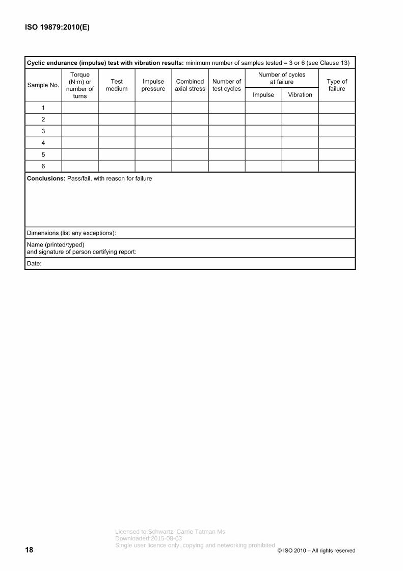
13 Cyclic endurance (impulse) test with vibration
13.1 Principle
Unless otherwise specified in the respective connector standard, three assemblies in accordance with Figure 8 shall be tested to confirm that they pass, without leakage or component failure, a cyclic endurance test at 133 % of working pressure for 500 000 cycles, while simultaneously being subjected to vibration. For flange assemblies of DN 51 and larger and connectors for tube OD sizes 50 mm and larger, the testing of three test assemblies shall be sufficient if the design has been verified through calculation or finite element analysis.
13.2 Procedure
13.2.1 Conduct the cyclic endurance (impulse) test with vibration in accordance with the requirements of Table 11 and Figure 8.
Table 11 — Parameters and procedures for the cyclic endurance (impulse) test with vibration
Test parameter Value of parameter and procedure
Test medium Hydraulic fluid in accordance with ISO 6743-4, e.g. HM, with a viscosity of ISO VG 32, in accordance with ISO 3448, or water.
The test medium shall be recorded in the test report.
Test pressure Test pressure shall conform to the waveform specified in ISO 6605 with peak pressure of 133 % of working pressure, with an impulse frequency of 0,5 Hz to 1,25 Hz.
Bending-test stress level 25 % of the minimum yield strength of the tubea.
Test vibration frequency × 20 the impulse frequency.
Test duration Minimum of 500 000 pressure-impulse cycles.
Pass/fail criterion None of the test assemblies shall leak or fail during the test.
a The use of tubes with minimum yield strength greater than 235 MPa requires that the dynamic capability of the tube be taken into consideration when determining the stress level used in the test.
13.2.2 Prepare the test assembly as shown in Figure 8. The strain gauge shall be installed at the location specified in Figure 8. The minimum gauge length, L, shall be in accordance with Table 10.
13.3 Re-use of components
Parts that pass this test shall not be tested further, nor used for actual service or returned to stock.
Licensed to:Schwartz, Carrie Tatman MsDownloaded:2015-08-03Single user licence only, copying and networking prohibited

ISO 19879:2010(E)
© ISO 2010 – All rights reserved 15
Dimensions in millimetres
Key 1 strain gauge 2 driven end 3 supply of hydraulic fluid or water 4 test assembly 5 fixed end
Figure 8 — Cyclic endurance (impulse) test with vibration test assembly and setup
14 Identification statement (Reference to this International Standard)
It is strongly recommended to manufacturers who have chosen to conform to this International Standard that the following statement be used in test reports, catalogues and sales literature:
“Test methods for metallic tube connections conform to ISO 19879:2005, Metallic tube connections for fluid power and general use — Test methods for hydraulic fluid power connections”.
Licensed to:Schwartz, Carrie Tatman MsDownloaded:2015-08-03Single user licence only, copying and networking prohibited

ISO 19879:2010(E)
16 © ISO 2010 – All rights reserved
Annex A (normative)
Test data form
Specifications for connection being tested:
ISO standard Material type
Manufacturer Test facility
Stud end: Type: Size: Sealing type:
Connector end: Type: Size: Sealing type:
Repeated assembly and leakage test results: minimum number of samples tested = 3 (see Clauses 5 and 6)
Sample No. Torque (N·m) or number of turns Test medium Type of failure
Repeated assembly Leakage test Proof test
After first assembly
1
2
3
After sixth reassembly
1
2
3
Proof pressure test results: minimum number of samples tested = 3 (see Clause 7)
Sample No. Torque (N·m) or number of turns Test medium Test pressure Type of failure
1 MPa
2 MPa
3 MPa
Burst test results: minimum number of samples tested = 3 (see Clause 8)
Sample No. Torque (N·m) or number of turns Test medium Test pressure Type of failure
1 MPa MPa
2 MPa MPa
3 MPa MPa
Licensed to:Schwartz, Carrie Tatman MsDownloaded:2015-08-03Single user licence only, copying and networking prohibited

ISO 19879:2010(E)
© ISO 2010 – All rights reserved 17
Cyclic endurance test results: minimum number of samples tested = 6 (see Clause 9)
Sample No.
Torque (N·m) or
number of turns
Test medium
Number of test cycles
Number of cyclesat failure Type of failure
1
2
3
4
5
6
Vacuum test results: minimum number of samples tested = 2 (see Clause 10)
Sample No. Torque (N·m) or number of turns Absolute pressure Type of failure
1 kPa
2 kPa
Overtightening test results: minimum number of samples tested = 6 (see Clause 11)
Nut type Torque (N·m) or number of turns Type of failure
1
2
3
4
5
6
Vibration test results: minimum number of samples tested = 6 (see Clause 12)
Sample No. Test pressure Combined axial stress
Number of test cycles
Number of cycles at failure Type of failure
1 MPa
2 MPa
3 MPa
4 MPa
5 MPa
6 MPa
Licensed to:Schwartz, Carrie Tatman MsDownloaded:2015-08-03Single user licence only, copying and networking prohibited
ISO 19879:2010(E)
18 © ISO 2010 – All rights reserved
Cyclic endurance (impulse) test with vibration results: minimum number of samples tested = 3 or 6 (see Clause 13)
Number of cycles at failure Sample No.
Torque (N·m) or
number of turns
Test medium
Impulse pressure
Combined axial stress
Number of test cycles
Impulse Vibration
Type of failure
1
2
3
4
5
6
Conclusions: Pass/fail, with reason for failure
Dimensions (list any exceptions):
Name (printed/typed) and signature of person certifying report:
Date:
Licensed to:Schwartz, Carrie Tatman MsDownloaded:2015-08-03Single user licence only, copying and networking prohibited

ISO 19879:2010(E)
© ISO 2010 – All rights reserved 19
Bibliography
[1] ISO 1179-2, Connections for general use and fluid power — Ports and stud ends with ISO 228-1 threads with elastomeric or metal-to-metal sealing — Part 2: Heavy-duty (S series) and light-duty (L series) stud ends with elastomeric sealing (type E)
[2] ISO 1179-3, Connections for general use and fluid power — Ports and stud ends with ISO 228-1 threads with elastomeric or metal-to-metal sealing — Part 3: Light-duty (L series) stud ends with sealing by O-ring with retaining ring (types G and H)
[3] ISO 1179-4, Connections for general use and fluid power — Ports and stud ends with ISO 228-1 threads with elastomeric or metal-to-metal sealing — Part 4: Stud ends for general use only with metal-to-metal sealing (type B)
[4] ISO 6149-2, Connections for hydraulic fluid power and general use — Ports and stud ends with ISO 261 metric threads and O-ring sealing — Part 2: Dimensions, design, test methods and requirements for heavy-duty (S series) stud ends
[5] ISO 6149-3, Connections for hydraulic fluid power and general use — Ports and stud ends with ISO 261 threads and O-ring sealing — Part 3: Dimensions, design, test methods and requirements for light-duty (L series) stud ends
[6] ISO 6162-1, Hydraulic fluid power — Flange connectors with split or one-piece flange clamps and metric or inch screws — Part 1: Flange connectors for use at pressures of 3,5 MPa (35 bar) to 35 MPa (350 bar), DN 13 to DN 127
[7] ISO 6162-2, Hydraulic fluid power — Flange connectors with split or one-piece flange clamps and metric or inch screws — Part 2: Flange connectors for use at pressures of 35 MPa (350 bar) to 40 MPa (400 bar), DN 13 to DN 51
[8] ISO 6164, Hydraulic fluid power –– Four-screw, one-piece square-flange connections for use at pressures of 25 MPa and 40 MPa (250 bar and 400 bar)
[9] ISO 7241-2, Hydraulic fluid power — Quick-action couplings — Part 2: Test methods
[10] ISO 8434-1, Metallic tube connections for fluid power and general use — Part 1: 24 degree cone connectors
[11] ISO 8434-2, Metallic tube connections for fluid power and general use — Part 2: 37 degree flared connectors
[12] ISO 8434-3, Metallic tube connections for fluid power and general use — Part 3: O-ring face seal connectors
[13] ISO 9974-2, Connections for general use and fluid power — Ports and stud ends with ISO 261 threads with elastomeric or metal-to-metal sealing — Part 2: Stud ends with elastomeric sealing (type E)
[14] ISO 9974-3, Connections for general use and fluid power — Ports and stud ends with ISO 261 threads with elastomeric or metal-to-metal sealing — Part 3: Stud ends with metal-to-metal sealing (type B)
[15] ISO/TR 11340, Rubber and rubber products — Hydraulic hose assemblies — External leakage classification for hydraulic systems
Licensed to:Schwartz, Carrie Tatman MsDownloaded:2015-08-03Single user licence only, copying and networking prohibited

ISO 19879:2010(E)
20 © ISO 2010 – All rights reserved
[16] ISO 11926-2, Connections for general use and fluid power — Ports and stud ends with ISO 263 inch threads and O-ring sealing — Part 2: Heavy-duty (S series) stud ends1)
[17] ISO 11926-3, Connections for general use and fluid power — Ports and stud ends with ISO 263 inch threads and O-ring sealing — Part 3: Light duty (L series) stud ends2)
1) To be published. (Revision of ISO 11926-2:1995)
2) To be published. (Revision of ISO 11926-3:1995)
Licensed to:Schwartz, Carrie Tatman MsDownloaded:2015-08-03Single user licence only, copying and networking prohibited

Licensed to:Schwartz, Carrie Tatman MsDownloaded:2015-08-03Single user licence only, copying and networking prohibited

ISO 19879:2010(E)
ICS 23.040.60; 23.100.40 Price based on 20 pages
© ISO 2010 – All rights reserved
Licensed to:Schwartz, Carrie Tatman MsDownloaded:2015-08-03Single user licence only, copying and networking prohibited


