Metallic tube connections for fluid power and general use … · In fluid power systems, power is...
50
THIS DOCUMENT IS A DRAFT CIRCULATED FOR COMMENT AND APPROVAL. IT IS THEREFORE SUBJECT TO CHANGE AND MAY NOT BE REFERRED TO AS AN INTERNATIONAL STANDARD UNTIL PUBLISHED AS SUCH. IN ADDITION TO THEIR EVALUATION AS BEING ACCEPTABLE FOR INDUSTRIAL, TECHNOLOGICAL, COMMERCIAL AND USER PURPOSES, DRAFT INTERNATIONAL STANDARDS MAY ON OCCASION HAVE TO BE CONSIDERED IN THE LIGHT OF THEIR POTENTIAL TO BECOME STANDARDS TO WHICH REFERENCE MAY BE MADE IN NATIONAL REGULATIONS. DRAFT INTERNATIONAL STANDARD ISO/DIS 8434-6 © International Organization for Standardization, 2007 INTERNATIONAL ORGANIZATION FOR STANDARDIZATION • МЕЖДУНАРОДНАЯ ОРГАНИЗАЦИЯ ПО СТАНДАРТИЗАЦИИ • ORGANISATION INTERNATIONALE DE NORMALISATION ISO/TC 131/SC 4 Voting begins on: 2007-01-29 Secretariat: ANSI Voting terminates on: 2007-06-29 Metallic tube connections for fluid power and general use — Part 6: 60° cone connectors with or without O-ring Raccords de tubes métalliques pour transmissions hydrauliques et pneumatiques et applications générales — Partie 6: Raccords coniques à 60° avec ou sans joint torique ICS 23.100.40 To expedite distribution, this document is circulated as received from the committee secretariat. ISO Central Secretariat work of editing and text composition will be undertaken at publication stage. Pour accélérer la distribution, le présent document est distribué tel qu'il est parvenu du secrétariat du comité. Le travail de rédaction et de composition de texte sera effectué au Secrétariat central de l'ISO au stade de publication.
Transcript of Metallic tube connections for fluid power and general use … · In fluid power systems, power is...

THIS DOCUMENT IS A DRAFT CIRCULATED FOR COMMENT AND APPROVAL. IT IS THEREFORE SUBJECT TO CHANGE AND MAY NOT BEREFERRED TO AS AN INTERNATIONAL STANDARD UNTIL PUBLISHED AS SUCH.
IN ADDITION TO THEIR EVALUATION AS BEING ACCEPTABLE FOR INDUSTRIAL, TECHNOLOGICAL, COMMERCIAL AND USER PURPOSES, DRAFTINTERNATIONAL STANDARDS MAY ON OCCASION HAVE TO BE CONSIDERED IN THE LIGHT OF THEIR POTENTIAL TO BECOME STANDARDS TOWHICH REFERENCE MAY BE MADE IN NATIONAL REGULATIONS.
DRAFT INTERNATIONAL STANDARD ISO/DIS 8434-6
© International Organization for Standardization, 2007
INTERNATIONAL ORGANIZATION FOR STANDARDIZATION • МЕЖДУНАРОДНАЯ ОРГАНИЗАЦИЯ ПО СТАНДАРТИЗАЦИИ • ORGANISATION INTERNATIONALE DE NORMALISATION
ISO/TC 131/SC 4
Voting begins on:2007-01-29
Secretariat: ANSI
Voting terminates on:2007-06-29
Metallic tube connections for fluid power and general use —
Part 6:60° cone connectors with or without O-ring
Raccords de tubes métalliques pour transmissions hydrauliques et pneumatiques et applications générales —
Partie 6: Raccords coniques à 60° avec ou sans joint torique
ICS 23.100.40
To expedite distribution, this document is circulated as received from the committee secretariat.ISO Central Secretariat work of editing and text composition will be undertaken at publicationstage.
Pour accélérer la distribution, le présent document est distribué tel qu'il est parvenu dusecrétariat du comité. Le travail de rédaction et de composition de texte sera effectué auSecrétariat central de l'ISO au stade de publication.

ISO/DIS 8434-6
ii © ISO 2007 – All rights reserved
PDF disclaimer
This PDF file may contain embedded typefaces. In accordance with Adobe's licensing policy, this file may be printed or viewed but shallnot be edited unless the typefaces which are embedded are licensed to and installed on the computer performing the editing. Indownloading this file, parties accept therein the responsibility of not infringing Adobe's licensing policy. The ISO Central Secretariataccepts no liability in this area.
Adobe is a trademark of Adobe Systems Incorporated.
Details of the software products used to create this PDF file can be found in the General Info relative to the file; the PDF-creationparameters were optimized for printing. Every care has been taken to ensure that the file is suitable for use by ISO member bodies. In theunlikely event that a problem relating to it is found, please inform the Central Secretariat at the address given below.
Copyright notice
This ISO document is a Draft International Standard and is copyright-protected by ISO. Except as permittedunder the applicable laws of the user's country, neither this ISO draft nor any extract from it may bereproduced, stored in a retrieval system or transmitted in any form or by any means, electronic, photocopying,recording or otherwise, without prior written permission being secured.
Requests for permission to reproduce should be addressed to either ISO at the address below or ISO'smember body in the country of the requester.
ISO copyright officeCase postale 56 • CH-1211 Geneva 20Tel. + 41 22 749 01 11Fax + 41 22 749 09 47E-mail [email protected] www.iso.org
Reproduction may be subject to royalty payments or a licensing agreement.
Violators may be prosecuted.
标准分享网 www.bzfxw.com 免费下载

ISO/DIS 8434-6
© ISO 2006 – All rights reserved iii
Contents
Foreword .................................................................................................................................................................iv Introduction..............................................................................................................................................................v 1 Scope ...........................................................................................................................................................1 2 Normative references .................................................................................................................................1 3 Terms and definitions.................................................................................................................................2 4 Materials ......................................................................................................................................................3 4.1 General ........................................................................................................................................................3 4.2 Connector bodies........................................................................................................................................4 4.3 Nuts..............................................................................................................................................................4 4.4 O-rings .........................................................................................................................................................4 5 Pressure/temperature requirements..........................................................................................................4 6 Designation of connectors .........................................................................................................................5 7 Requirements for tubes..............................................................................................................................6 8 Across-flats dimensions and tolerances ..................................................................................................7 9 Design..........................................................................................................................................................7 9.1 Connectors ..................................................................................................................................................7 9.2 Dimensions..................................................................................................................................................7 9.3 Passage tolerances.....................................................................................................................................7 9.4 Angular tolerances......................................................................................................................................8 9.5 Contour details............................................................................................................................................8 9.6 Ports and stud ends....................................................................................................................................8 10 Screw threads .............................................................................................................................................8 10.1 60° cone connection ends..........................................................................................................................8 10.2 Stud ends (connection ends) .....................................................................................................................8 11 Manufacture.................................................................................................................................................8 11.1 Construction................................................................................................................................................8 11.2 Workmanship ..............................................................................................................................................8 11.3 Finish ...........................................................................................................................................................9 11.4 Connector protection..................................................................................................................................9 11.5 Corners ........................................................................................................................................................9 12 Assembly instruction..................................................................................................................................9 13 Procurement information .........................................................................................................................10 14 Marking of components............................................................................................................................10 15 Performance and qualification test..........................................................................................................10 15.1 Performance requirements.......................................................................................................................10 15.2 Test data form ...........................................................................................................................................12 16 Identification statement (reference to this part of ISO 8434) ....................................................................12 Bibliography...........................................................................................................................................................44

ISO/DIS 8434-6
iv © ISO 2006 – All rights reserved
Foreword
ISO (the International Organization for Standardization) is a worldwide federation of national standards bodies (ISO member bodies). The work of preparing International Standards is normally carried out through ISO technical committees. Each member body interested in a subject for which a technical committee has been established has the right to be represented on that committee. International organizations, governmental and non-governmental, in liaison with ISO, also take part in the work. ISO collaborates closely with the International Electrotechnical Commission (IEC) on all matters of electrotechnical standardization.
International Standards are drafted in accordance with the rules given in the ISO/IEC Directives, Part 2.
Draft International Standards adopted by the technical committees are circulated to the member bodies for voting. Publication as an International Standard requires approval by at least 75 % of the member bodies casting a vote.
International Standard ISO 8434-6 was prepared by Technical Committee ISO/TC 131, Fluid power systems, Subcommittee SC 4, Connectors and similar products and components.
ISO 8434 consists of the following parts, under the general title Metallic tube connections for fluid power and general use:
⎯ Part 1: 24° cone connectors
⎯ Part 2: 37° flared connectors
⎯ Part 3: O-ring face seal connectors
⎯ Part 4: 24° cone connectors with O-ring weld-on nipples
⎯ Part 6: 60° cone connectors with or without O-ring
This part of ISO 8434 is based on British standard BS 5200. The threads for the 60° cone connection are pipe threads conforming to ISO 228-1.
标准分享网 www.bzfxw.com 免费下载

ISO/DIS 8434-6
© ISO 2006 – All rights reserved v
Introduction
In fluid power systems, power is transmitted and controlled through a fluid (liquid or gas) under pressure within an enclosed circuit. In general applications, a fluid may be conveyed under pressure.
Components may be connected through their ports by connections (connectors) and conductors (tubes and hoses). Tubes are rigid conductors; hoses are flexible conductors.

标准分享网 www.bzfxw.com 免费下载
DRAFT INTERNATIONAL STANDARD ISO/DIS 8434-6
© ISO 2006 – All rights reserved 1
Metallic tube connections for fluid power and general use — Part 6: 60° cone connectors with or without O-ring
1 Scope
This part of ISO 8434 specifies general and dimensional requirements for the design and performance of 60° cone connectors and braze-on nipples with or without O-ring sealing, made of steel for tube outside diameters of 6 mm through 50 mm, inclusive, or hose sizes 5 through 51, inclusive. These connectors are for use in fluid power and general applications within the limits of pressure and temperature specified in this part of ISO 8434.
They are intended for the connection of tubes and hose fittings to ports in accordance with ISO 6149-1 and ISO 1179-1 (see ISO 12151-6 for related hose fitting specification).
These connectors provide full-flow connections in hydraulic systems operating to the working pressures shown in Table 1. Because many factors influence the pressure at which a system performs satisfactorily, these values shall not be understood as guaranteed minimums. For every application, it is recommended that sufficient testing be conducted and reviewed by both the user and manufacturer to ensure that required performance levels are met.
NOTE 1 For new designs in hydraulic fluid power applications, see the requirements given in 9.6. Where the requirements of the application allow for the use of elastomeric seals, connector designs that conform to International Standards and incorporate elastomeric sealing are preferred.
NOTE 2 For use under conditions outside the pressure and/or temperature limits specified, see 5.3
2 Normative references
The following referenced documents are indispensable for the application of this document. For dated references, only the edition cited applies. For undated references, the latest edition of the referenced document (including any amendments) applies.
ISO 48, Rubber, vulcanized or thermoplastic –– Determination of hardness (hardness between 10 IRHD and 100 IRHD)
ISO 228-1, Pipe threads where pressure-tight joints are not made on the threads — Part 1: Dimensions, tolerances and designation
ISO 261, ISO general-purpose metric screw threads — General plan
ISO 1179-11), Connections for general use and fluid power — Ports and stud ends with ISO 228-1 threads with elastomeric or metal-to-metal sealing — Part 1: Threaded ports
ISO 1179-22), Connections for general use and fluid power — Ports and stud ends with ISO 228-1 threads with elastomeric or metal-to-metal sealing — Part 2: Heavy-duty (S series) and light-duty (L series) stud ends with elastomeric sealing (type E)
1) To be published; revision in part of ISO 1179:1981. 2) To be published; revision in part of ISO 1179:1981.

ISO/DIS 8434-6
2 © ISO 2006 – All rights reserved
ISO 1179-33), Connections for general use and fluid power — Ports and stud ends with ISO 228-1 threads with elastomeric or metal-to-metal sealing — Part 3: Light-duty (L series) stud ends with sealing by O-ring with retaining ring (types G and H)
ISO 3304, Plain end seamless precision steel tubes — Technical conditions for delivery
ISO 3305, Plain end welding precision steel tubes — Technical conditions for delivery
ISO 3601-3, Fluid power systems – Sealing devices – O-rings – Part 3: Quality acceptance criteria
ISO 4759-1, Tolerances for fasteners — Part 1: Bolts, screws, studs and nuts –– Product grades A, B and C
ISO 55984), Fluid power systems and components — Vocabulary
ISO 6149-3, Connections for fluid power and general use — Ports and stud ends with ISO 261 metric threads and O-ring sealing — Part 3: Dimensions, design, test methods and requirements for light-duty (L series) stud ends
ISO 9227, Corrosion tests in artificial atmospheres — Salt spray tests
ISO 10763, Hydraulic fluid power –– Plain-end, seamless and welded precision steel tubes — Dimensions and nominal working pressures
ISO 12151-65), Connections for hydraulic fluid power and general use –– Hose fittings –– Part 6: Hose fittings with ISO 8434-6 60 degree cone ends
ISO 19879, Metallic tube connections for fluid power and general use –– Test methods for hydraulic fluid power connections
3 Terms and definitions
For the purposes of this part of ISO 8434, the terms and definitions given in ISO 5598 and the following apply.
3.1 fluid power means whereby energy is transmitted, controlled and distributed using a pressurized fluid as the medium
[ISO 5598]
3.2 connector leakproof device to connect pipelines (conductors) to one another, or to equipment
[ISO 5598]
3.3 fastening thread terminal thread of a complete connector
3.4 run two principal, axially aligned outlets of a tee or cross
3) To be published; revision in part of ISO 1179:1981. 4) Under revision. 5) To be published.
标准分享网 www.bzfxw.com 免费下载

ISO/DIS 8434-6
© ISO 2006 – All rights reserved 3
3.5 branch side outlet(s) of a tee or cross
3.6 chamfer removal of a conical portion at the entrance of a thread to assist assembly and prevent damage to the start of a thread
3.7 assembly torque torque to be applied in order to achieve a satisfactory final assembly
3.8 rated pressure pressure, confirmed through testing, at which a component or piping is designed to operate for a number of repetitions sufficient to assure adequate service life.
[ISO/DIS 5598]
3.9 adjustable stud end stud end connector that allows for connector orientation through final tightening of the locknut to complete the connection.
NOTE This type of stud end is typically used on shaped connectors (e.g. tees, crosses and elbows).
3.10 nonadjustable stud end stud end connector that does not require specific orientation through final tightening of the connection because it is only used on straight connectors
4 Materials
4.1 General
Figure 1 shows the cross-section and component parts of a typical 60° cone connector with O-ring.
Key 1 Male body 2 Nut 3 O-ring 4 Female nipple
Figure 1 — Cross-section of typical 60° cone connector with O-ring
12
3 4

ISO/DIS 8434-6
4 © ISO 2006 – All rights reserved
4.2 Connector bodies
Bodies shall be manufactured from carbon steel or stainless steel that will provide the minimum pressure/temperature requirements specified in Clause 5. They shall have characteristics that make them suitable for use with the fluid to be conveyed and that will provide an effective joint. Weld-on nipples shall be made of materials classified as suitable for welding.
4.3 Nuts
Nuts to be used with carbon steel bodies shall be made of carbon steel and those for use with stainless steel bodies shall be made of stainless steel, unless otherwise specified.
4.4 O-rings
Unless otherwise specified, for use with petroleum base hydraulic fluids at the pressure and temperature requirements in Clause 5 and Table 1 and for testing, the O-rings shall be made of NBR (nitrile) with a hardness of (90 ±5) IRHD, measured in accordance with ISO 48, shall conform to the dimensions given in Table 5 and shall meet or exceed the O-ring quality acceptance criteria for grade N of ISO 3601-3. In those cases where the pressure and temperature requirements of this part of ISO 8434 and/or the hydraulic fluid used in the system differ from those specified in Clause 5 and Table 1, the connector manufacturer shall be consulted to ensure that an appropriate O-ring material is selected.
5 Pressure/temperature requirements
5.1 60° cone connectors in conformance with this part of ISO 8434 made of carbon steel shall meet or exceed without leakage the requirements from a vacuum of 6,5 kPa (0,065 bar) absolute pressure to the rated pressures given in Table 1 when used at temperatures between –40 °C and +120 °C. For stud end connectors, the upper limit shall be the lower of the rated pressure given in Table 1 and the rated pressure for the relevant stud end, i.e., ISO 1179-2, ISO 1179-3 or ISO 6149-3.
Table 1 –– Rated pressures for 60° cone connector ends
Rated pressurea With O-ring Without O-ring
Tube outside
diameter
Thread size
MPa (bar) MPa (bar)
6 G 1/8 A – – 35 (350)
8 G 1/4 A 40 (400) 35 (350)
10 G 3/8 A 40 (400) 35 (350)
12 G 1/2 A 35 (350) 31,5 (315)
16 G 5/8 A 35 (350) 31,5 (315)
20 G 3/4 A 31,5 (315) 25 (250
25 G 1 A 25 (250) 20 (200)
32 G 1 ¼ A 20 (200) 16 (160)
38 G 1 ½ A 16 (160) 12,5 (125)
50 G 2 A 12,5 (125) 8 (80) a See 5.1.
5.2 The connector assembly shall meet or exceed all applicable performance requirements given in Clause 15. Testing shall be conducted at room temperature.
5.3 For applications under conditions outside the temperature and/or pressure limits given in Table 1 and 5.1 and 5.2, the manufacturer shall be consulted.
标准分享网 www.bzfxw.com 免费下载

ISO/DIS 8434-6
© ISO 2006 – All rights reserved 5
6 Designation of connectors
6.1 Connectors shall be designated by an alphanumeric code to facilitate ordering. They shall be designated by the word “Connector” followed by ISO 8434-6, followed by a hyphen, then the connector style letter symbols (see 6.2), followed by a spaced hyphen and, for the ends, the outside diameter of the tube with which they are to be connected, each separated by a multiplication symbol (×). For stud ends (connector ends), the thread designation and the number of the relevant standard shall be added.
EXAMPLE
A straight stud connector (SDS) for use with 12 mm OD tubing with a light-duty (L series) M18 × 1,5 stud end, in accordance with ISO 6149-3, is designated as follows:
Connector ISO 8434-6-SDS - 12 × M18 - ISO 6149-3
6.2 The letter symbol designation of the connector style shall have two parts: the connection end type immediately followed by the shape of the connector. The letters A and B shall be used to distinguish different styles, where such options exist.
6.3 Tube ends are assumed and thus do not need to be included in the code. However, if another type of end is involved, it shall be designated.
6.4 Reducing connectors and reducing elbows shall be designated by specifying the larger tube end first. For reducing swivel type connectors, the swivel end shall be designated first.
6.5 Stud connectors shall be designated by specifying the tube end first, then the thread size for the stud end.
6.6 For tee connectors, the order of designation of the connection ends shall be from larger tube end to the smaller tube end on the run, followed by the branch end.
6.7 For cross connectors, the order of designation of the connection ends shall be from left to right, followed by top to bottom, with larger ends on the left and at the top.
Size code
Connector style letter symbol

ISO/DIS 8434-6
6 © ISO 2006 – All rights reserved
6.8 The following letter symbols shall be used:
Connection end type Letter Bulkhead BH Swivel SW Weld-on WD Braze-on BR Port P Stud SD
Shape Letter
Straight S Elbow E 45° elbow E45 Tee T Run tee RT Branch tee BT Cross K Long L
Component type Letter
Nut N Sleeve SL Locknut LN Plug PL Cap CP Nipple NP Metric M Inch (imperial) I
7 Requirements for tubes
7.1 The connectors shall be suitable for use with tubes with limits of outside diameter given in Table 2. These limits include ovality.
7.2 Tubing shall comply with the relevant dimensions given in Table 2 and shall be selected in accordance with ISO 10763 for appropriate rated pressures.
标准分享网 www.bzfxw.com 免费下载

ISO/DIS 8434-6
© ISO 2006 – All rights reserved 7
Table 2 — Tube sizes
Tube outside
diameter Limits of outside diameter
mmmm min. max.
6 5,9 6,1 8 7,9 8,1 10 9,9 10,1 12 11,9 12,1 16 15,9 16,1 20 19,9 20,1 25 24,9 25,1 30 29,85 30,15 38 37,85 38,15 50 49,8 50,2
7.3 Carbon steel tubes shall comply with ISO 3304 (seamless cold-finished as-drawn or annealed or normalized) or ISO 3305 (welded cold-finished as-drawn or annealed or normalized).
8 Across-flats dimensions and tolerances
8.1 The dimensions across flats of elbow and tee connectors shall have a minus tolerance only. For sizes up to and including 24 mm, tolerances for across-flats dimensions for forgings shall be +0/-0,8 mm, and for sizes larger than 24 mm, they shall be +0/-1 mm. The basic forging size may be increased up to the maximum size shown for barstock, but the size selected shall be a metric across-flat size with minus tolerance only.
8.2 Hex tolerances across flats shall be in accordance with ISO 4759-1, product grade C. Minimum across-corner hex dimensions are 1,092 times the nominal width across flats. The minimum side flat is 0,43 times the nominal width across flats. Unless otherwise specified or shown, hex corners shall be chamfered 15° to 30° to a diameter equal to the width across flats, with a tolerance of +0/-0,4 mm.
9 Design
9.1 Connectors
The connectors shall conform to the requirements given in Figures 2 through 33 and Tables 3 through 21. They shall be designed so that resistance to flow is reduced to a minimum.
9.2 Dimensions
Dimensions specified apply to finished parts, including any plating or other treatments. The tolerance value for all dimensions not otherwise limited shall be ±0,4 mm.
9.3 Passage tolerances
Where passages in straight connectors are machined from opposite ends, the offset at the meeting point shall not exceed 0,4 mm. No cross-sectional area at a junction of passages shall be less than that of the smallest passage.

ISO/DIS 8434-6
8 © ISO 2006 – All rights reserved
9.4 Angular tolerances
Angular tolerances on axis of end on elbows, tees and crosses shall be ±2,5° for tube sizes up to and including 10 mm and ±1,5° for all larger sizes.
9.5 Contour details
Details of contour shall be chosen by the manufacturer provided the dimensions given in Tables 5 to 22 are maintained. Wrench flats on elbows and tees shall conform to the dimensions in the relevant tables. Abrupt reduction of a section shall be avoided. Junctions of small external sections and adjoining sections that are relatively heavy shall be blended by means of ample fillets.
9.6 Ports and stud ends
These connectors are intended for connection of plain end tubes and hose fittings to ports in accordance with ISO 6149-1 and ISO 1179-1. For new designs in hydraulic fluid power applications, only ports and stud ends in accordance with the relevant parts of ISO 6149 shall be used. Ports and stud ends in accordance with the relevant parts of ISO 1179 shall not be used for new designs in hydraulic fluid power applications.
10 Screw threads
10.1 60° cone connection ends
The screw threads on the 60° cone connection ends shall be pipe threads in accordance with class A of ISO 228-1.
10.2 Stud ends (connection ends)
The screw threads for the stud ends of connectors shall be chosen from ISO 261 for ISO 6149-3 and ISO 228-1 (class A) for ISO 1179-2 and -3.
11 Manufacture
11.1 Construction
Carbon steel connectors made from multiple components shall be bonded together with materials having a melting point of not less than 1 000 °C.
11.2 Workmanship
Workmanship shall conform to the best commercial practice to produce high-quality connectors. Connectors shall be free from visual contaminants, all hanging burrs, loose scale and slivers which might be dislodged in use and any other defects that might affect the function of the parts. All machined surfaces shall have a surface roughness value of Ra max 6,3 μm, except where otherwise specified.
标准分享网 www.bzfxw.com 免费下载

ISO/DIS 8434-6
© ISO 2006 – All rights reserved 9
11.3 Finish
The external surface and threads on all connectors, except braze-on type components and weld-on nipples, shall be plated or coated with a suitable material that passes a 72-h neutral salt spray test in accordance with ISO 9227, unless otherwise agreed upon by the manufacturer and user. Any appearance of red rust during the salt spray test on any area, except those noted below, shall be considered failure:
— all internal fluid passages;
⎯ edges, such as hex points, serrations and crests of threads, where there may be mechanical deformation of the plating or coating typical of mass-produced parts or shipping effects;
⎯ areas where there is a mechanical deformation of the plating or coating caused by crimping, flaring, bending and other post-plate metal forming operations;
⎯ areas where the parts are suspended or affixed in the test chamber where condensate can accumulate.
Fluid passages shall be excluded from the plating and/or coating requirements but shall be protected from rust.
Braze-on type connectors, braze sleeves and weld nipples shall be protected from corrosion by an oil film or phosphate coating or by another method that does not negatively affect their ability to be welded or brazed.
Parts manufactured in accordance with this part of ISO 8434 shall not be cadmium plated. Changes in plating may affect assembly torques and require requalification, when applicable.
11.4 Connector protection
By a method agreed upon between manufacturer and user, the face of the connectors and threads (both internal and external) shall be protected by the manufacturer from nicks and scratches that would be detrimental to the function of the connector. Passages shall be securely covered to prevent the entrance of dirt or other contaminants. Covers that contribute to contamination shall not be used.
Braze-on type connectors require protection on the sealing face and threaded end only. Nuts and sleeves that are furnished separately from the connector shall be protected from rust but do not require capping.
11.5 Corners
Unless otherwise noted, all sharp corners shall be broken to 0,15 mm max.
12 Assembly instruction
The assembly of the connectors with the connecting tubes shall be carried out without external loads.
The manufacturer shall draw up assembly instructions for the use of the connectors. These instructions shall include at least the following:
⎯ details relating to material and quality of suitable tubes;
⎯ details concerning the preparation of selected tube;
⎯ details concerning the attachment of the braze sleeve and weld nipple to the tube;
⎯ instructions regarding the assembly of the connector, such as number of wrenching turns or assembly torque;
⎯ recommendations regarding the tools to be used for assembly.

ISO/DIS 8434-6
10 © ISO 2006 – All rights reserved
13 Procurement information
The following information should be supplied by the purchaser when making an inquiry or placing an order:
⎯ description of connector;
⎯ material of connector;
⎯ material and size of tube;
⎯ fluid to be conveyed;
⎯ rated pressure;
⎯ fluid working temperature range;
— ambient temperature range.
14 Marking of components
Connector bodies and nuts shall be permanently marked with the manufacturer's name, trademark or code identifier, unless otherwise agreed upon by the user and manufacturer.
15 Performance and qualification test
15.1 Performance requirements
15.1.1 Special requirements
The connectors shall be tested at the lower of the test pressure specified in Table 3 or in the standard for the relevant stud end, i.e., ISO 1179-2, ISO 1179-3 or ISO 6149-3. All components requiring copper brazing for assembly shall be processed through a 1 000 °C minimum annealing process before burst, cyclic endurance or overtightening testing.
标准分享网 www.bzfxw.com 免费下载

ISO/DIS 8434-6
© ISO 2006 – All rights reserved 11
Table 3 — Test pressures for 60° cone connectors
Nipple style With O-ring (Style A) Without O-ring (Style B)
Test pressures Test pressures
Nominal
size Rated
pressure Proof Burst ImpulseaRated
pressure Proof Burst Impulsea
mm
Thread
size
MPa (bar) MPa (bar) MPa (bar) MPa (bar) MPa (bar) MPa (bar) MPa (bar) MPa (bar)
6 G 1/8 A – – – – 35 (350) 70 (700) 140 (1400) 46,6 (466)
8 G 1/4 A 40 (400) 80 (800) 160 (1600) 53,2 (532) 35 (350) 70 (700) 140 (1400) 46,6 (466)
10 G 3/8 A 40 (400) 80 (800) 160 (1600) 53,2 (532) 35 (350) 70 (700) 140 (1400) 46,6 (466)
12 G 1/2 A 35 (350) 70 (700) 140 (1400) 46,6 (466) 31,5 (315) 63 (630) 126 (1260) 41,9 (419)
16 G 5/8 A 35 (350) 70 (700) 140 (1400) 46,6 (466) 31,5 (315) 63 (630) 126 (1260) 41,9 (419)
20 G 3/4 A 31,5 (315) 63 (630) 126 (1260) 41,9 (419) 25 (250) 50 (500) 100 (1000) 33,2 (332)
25 G 1 A 25 (250) 50 (500) 100 (1000) 33,2 (332) 20 (200) 40 (400) 80 (800) 26,6 (266)
32 G 1 ¼ A 20 (200) 40 (400) 80 (800) 26,6 (266) 16 (160) 32 (320) 64 (640) 21,3 (213)
38 G 1 ½ A 16 (160) 32 (320) 64 (640) 21,3 (213) 12,5 (125) 25 (250) 50 (500) 16,6 (166)
50 G 2 A 12,5 (125) 25 (250) 50 (500) 16,6 (166) 8 (80) 16 (160) 32 (320) 10,6 (106)
a Cyclic endurance (impulse) test pressure.
15.1.2 Proof test
For each size and nipple, nine test assemblies in accordance with ISO 19879 shall be subjected to the proof test procedure specified in ISO 19879, prior to burst and cyclic endurance tests. They shall not leak at the proof pressures given in Table 3.
15.1.3 Burst test
Three of the test assemblies that had been subjected to the proof test in 15.1.2 shall be used for the burst test. The test shall be conducted in accordance with the burst test procedure specified in ISO 19879 and at the minimum torque values given in Table 4. The test assemblies shall meet or exceed the minimum required burst pressures given in Table 3.
Table 4 — Qualification test torque requirements
60° cone connector
Torque Overtorque Styles A and B
N • m N • m
Tube size
+10 % -0 %
+10 % -0 %
mm
Thread size
Style A Style B 6 G 1/8 A –– 10 13 8 G 1/4 A 20 20 25
10 G 3/8 A 35 35 45 12 G 1/2 A 50 60 80 16 G 5/8 A 60 70 90 20 G 3/4 A 85 115 140 25 G 1 A 115 140 170 32 G 1 ¼ A 190 210 280 38 G 1 ½ A 240 290 370 50 G 2 A 300 400 500
NOTE Refer to ISO 6149-3, ISO 1179-2 or ISO 1179-3 for stud end test torque values.

ISO/DIS 8434-6
12 © ISO 2006 – All rights reserved
15.1.4 Cyclic endurance (impulse) test
The remaining six test assemblies that had been subjected to the proof test in 15.1.2 shall be subjected to the cyclic endurance test procedure specified in ISO 19879. The test shall be conducted at minimum torque values given in Table 4. The test assemblies shall pass a cyclic endurance test for 1 000 000 cycles at the respective impulse pressures given in Table 3.
15.1.5 Vacuum test
For each size and nipple style, two test assemblies in accordance with ISO 19879 shall be subjected to the vacuum test procedure specified in ISO 19879. Connectors shall be capable of withstanding a vacuum of 6,5 kPa (0,065 bar) absolute pressure for 5 min without leakage.
15.1.6 Overtightening test
For each size, nipple style and swivel nut design, three samples shall be subjected to the overtightening test specified in ISO 19879. Connector swivel nuts shall be capable of withstanding the overtightening qualification test with no indication of failure when torqued to the overtorque values given in Table 4.
15.1.7 Re-use of test samples
Parts used for cyclic endurance, burst or overtightening test shall not be tested further, used or returned to stock.
15.2 Test data form
Test data shall be reported in accordance with ISO 19879.
16 Identification statement (reference to this part of ISO 8434)
Use the following statement in test reports, catalogues and sales literature when electing to comply with this part of ISO 8434:
"Dimensions and design for 60° cone connectors in accordance with ISO 8434-6, Metallic tube connections for fluid power and general use — Part 6: 60° cone connectors with or without O-ring."
标准分享网 www.bzfxw.com 免费下载

ISO/DIS 8434-6
© ISO 2006 – All rights reserved 13
Surface roughness in micrometres
Key 1 Thread 2 Pitch diameter 3 Thread chamfer NOTE Surface texture on 60° cone shall be annular. a Preferred undercut; see Figure 34.
Figure 2 — Details of end for male connector

ISO/DIS 8434-6
14 © ISO 2006 – All rights reserved
Surface roughness in micrometres
Key 1 Enlarged view A of O-ring groove 2 O-ring 3 Thread 4 Pitch diameter a Method of attachment of the swivel nut is optional with the manufacturer. Nuts shall be free to rotate. Hexagon S across flats.
Figure 3 — Details of swivel female end with O-ring sealing nipple (style A)
标准分享网 www.bzfxw.com 免费下载

ISO/DIS 8434-6
© ISO 2006 – All rights reserved 15
Surface roughness in micrometres
Key 1 Thread NOTE Surface texture on 60° cone shall be annular. a Method of attachment of the swivel nut is optional with the manufacturer. Nuts shall be free to rotate. Hexagon S across flats.
Figure 4 — Details of end for swivel female connector (style B)

ISO/DIS 8434-6
16 © ISO 2006 – All rights reserved
Table 5 — Interface dimensions of male and swivel female 60° cone connectors
Dimensions in millimetres
Thread sizea
Tube size d1 d2 d3 d4 d5 d6 l1 l2 l3 l4 Sb c
±0,15 nom tol.± ±0,15 ±0,15 ±0,15 max ±0,25 ±0,25 ±0,50 min
G 1/8 A 6 7,5 3,5 0,1 8,13 8,35 5,6 3,5 8 2 4,3 5,0 14 G 1/4 A 8 10,4 4,7 0,1 11,05 11,25 7,2 4,5 11 3 5,2 7,0 19 G 3/8 A 10 14,0 7,9 0,2 14,48 14,75 10,4 7,1 12 3 6,0 9,0 22 G 1/2 A 12 17,5 11,1 0,2 18,13 18,35 13,5 9,7 14 4 6,5 10,0 27 G 5/8 A 16 19,3 14,3 0,2 20,04 20,35 16,8 12,0 16 4 9,7 11,0 30 G 3/4 A 20 22,9 16,7 0,2 23,6 23,9 19,0 15,5 16 4 8,7 12,0 32 G 1 A 25 28,7 22,2 0,2 29,82 29,95 24,6 20,4 19 5 10,5 13,0 41
G 1¼ A 32 36,8 28,6 0,2 38,23 38,55 31,1 26,0 20 5 10,1 15,0 50 G 1½ A 38 42,7 33,3 0,3 44,07 44,45 37,2 30,8 22 5 12,5 15,0 55 G 2 A 50 54,6 46,0 0,3 55,88 56,3 50,0 43,5 25 5 16,1 18,0 70
Thread sizea
Tube size O-ring groove O-ring
d7 d8 d9 d24 l5 r1 r2 d10 d11 ±0,05 ±0,05 ±0,05 P.O.I. ±0,05 ±0,10 ±0,10 nom. tol. nom. tol.
G 1/8 A 6 –– –– –– –– –– –– –– –– –– –– –– G 1/4 A 8 6,72 6,23 8,70 6,84 1,37 0,20 0,2 6,11 ±0,15 1,0 ±0,08
G 3/8 A 10 9,80 9,07 12,90 10,02 2,23 0,36 0,41 8,1 ±0,15 1,6 ±0,08
G 1/2 A 12 12,85 12,13 15,95 13,07 2,23 0,36 0,41 12,1 ±0,20 1,6 ±0,08 G 5/8 A 16 14,90 14,17 18,00 15,12 2,23 0,36 0,41 13,1 ±0,20 1,6 ±0,08
G 3/4 A 20 18,44 17,72 21,55 18,66 2,23 0,36 0,41 17,1 ±0,20 1,6 ±0,08
G 1 A 25 23,59 22,86 26,70 23,81 2,23 0,36 0,41 22,1 ±0,25 1,6 ±0,08 G 1¼ A 32 30,51 29,78 33,60 30,73 2,23 0,36 0,41 29,1 ±0,25 1,6 ±0,08 G 1½ A 38 36,68 35,95 39,75 36,90 2,23 0,36 0,41 35,1 ±0,30 1,6 ±0,08
G 2 A 50 49,20 48,47 52,30 49,42 2,23 0,36 0,41 47,37 ±0,30 1,78 ±0,08 a In accordance with ISO 228-1. b In accordance with ISO 4759-1, class C. c Optional S across flats hex 36 for G 3/4 A.
标准分享网 www.bzfxw.com 免费下载

ISO/DIS 8434-6
© ISO 2006 – All rights reserved 17
Key 1 For cone and nut detail, see Figure 3 or 4. NOTE 1 For style A, fit O-ring after brazing. NOTE 2 Nut to be assembled after brazing and protective finish. a Undercut details to manufacturer’s specification.
Figure 5 — Braze-on nipple (BRNP)
Table 6 — Dimensions of braze-on nipples (BRNP)
Dimensions in millimetres
Nipple size
Tube OD
d12 d13 l6 l7 L8
± 0,05 ± 0,15 ± 0,5 ± 0,80 max.
G 1/8 A 6 6,15 10 8,5 12,5 21,5 G 1/4 A 8 8,15 13 8,5 12,5 24,5 G 3/8 A 10 10,15 16 8,5 12,5 25,5 G 1/2 A 12 12,15 20 8,5 12,5 27,5 G 5/8 A 16 16,15 22 9,0 13,0 28,0 G 3/4 A 20 20,18 26 12,5 17,0 32,0 G 1 A 25 25,18 32 14,0 22,0 39,0
G 1 ¼ A 32 32,20 40 14,0 22,0 39,0 G 1 ½ A 38 38,20 46 14,0 22,0 46,0 G 2 A 50 50,25 60 14,0 22,0 46,0

ISO/DIS 8434-6
18 © ISO 2006 – All rights reserved
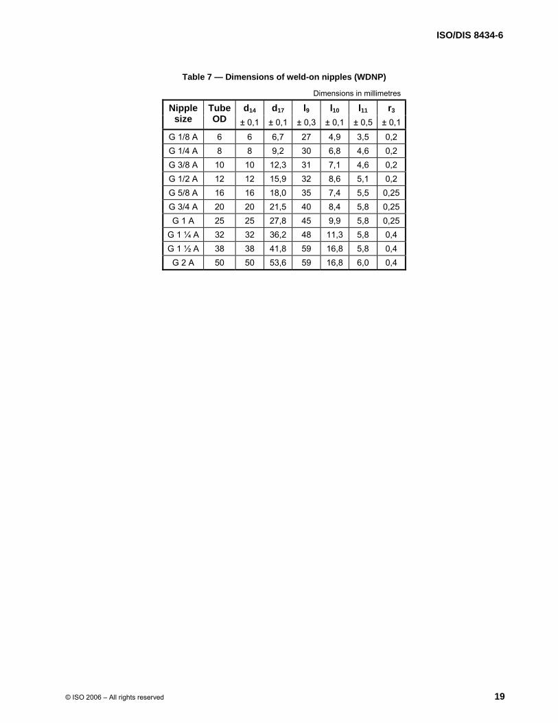
Key 1 For cone detail, see Figure 3 or 4. For nut detail, see Figure 7. NOTE 1 For style A nipple, fit O-ring after welding. NOTE 2 Diameter d14 is the outside diameter of the selected tube.
Figure 6 — Weld-on nipple (WDNP)
标准分享网 www.bzfxw.com 免费下载
ISO/DIS 8434-6
© ISO 2006 – All rights reserved 19
Table 7 — Dimensions of weld-on nipples (WDNP)
Dimensions in millimetres
d14 d17 l9 l10 l11 r3 Nipple size
Tube OD ± 0,1 ± 0,1 ± 0,3 ± 0,1 ± 0,5 ± 0,1
G 1/8 A 6 6 6,7 27 4,9 3,5 0,2 G 1/4 A 8 8 9,2 30 6,8 4,6 0,2 G 3/8 A 10 10 12,3 31 7,1 4,6 0,2 G 1/2 A 12 12 15,9 32 8,6 5,1 0,2 G 5/8 A 16 16 18,0 35 7,4 5,5 0,25 G 3/4 A 20 20 21,5 40 8,4 5,8 0,25 G 1 A 25 25 27,8 45 9,9 5,8 0,25
G 1 ¼ A 32 32 36,2 48 11,3 5,8 0,4 G 1 ½ A 38 38 41,8 59 16,8 5,8 0,4 G 2 A 50 50 53,6 59 16,8 6,0 0,4

ISO/DIS 8434-6
20 © ISO 2006 – All rights reserved
Key 1 Both sides 2 Thread 3 Thread core diameter
Figure 7 — Loose style nut for weld-on nipple
Table 8 — Dimensions of loose style nuts for weld-on nipples (N)
Dimensions in millimetres
Thread core diameter
d18
d19
d20
l12
l13
l14
Sa
acrossflats
Thread
size
Tube OD
nom. tol. ± 0,15 ± 0,30 ± 0,10 ± 0,25 min. ± 0,1 G 1/8 A 6 8,8 ±0,1 10,24 13,0 7,0 12,1 6,9 2,6 14 G 1/4 A 8 11,8 ±0,1 13,66 18,0 9,5 15,0 9,2 3,1 19 G 3/8 A 10 15,25 ±0,2 17,17 21,0 12,6 17,0 10,7 3,5 22 G 1/2 A 12 19,05 ±0,2 21,46 26,0 16,2 20,1 12,9 3,9 27 G 5/8 A 16 21,03 ±0,2 23,42 29,0 18,3 21,8 14,2 4,2 30 G 3/4 A 20 24,6 ±0,2 27,20 31,0 21,8 22,6 14,2 4,6 32 G 1 A 25 30,9 ±0,3 33,76 39,5 28,2 27,6 14,2 4,6 41
G 1 ¼ A 32 39,6 ±0,3 42,42 48,5 36,6 27,6 16,5 4,6 50 G 1 ½ A 38 45,5 ±0,3 48,80 53,5 42,2 35,0 19,4 4,6 55 G 2 A 50 57,15 ±0,3 60,96 68,5 54,1 37,5 21,3 4,9 70
a Optional S hex across flats 36 for G 3/4 A.
标准分享网 www.bzfxw.com 免费下载

ISO/DIS 8434-6
© ISO 2006 – All rights reserved 21
a See Figure 2 for detail.
Figure 8 — Braze-on straight connector (BRS)
Table 9 — Dimensions of braze-on straight connectors (BRS)
Dimensions in millimetres
d21 l15 l16 l17 S1 Nipple size Tube OD ± 0,05 ± 0,5 ± 0,80 ref. min.
G 1/8 A 6 6,15 8,5 12,5 20,5 10 G 1/4 A 8 8,15 8,5 12,5 23,5 14 G 3/8 A 10 10,15 8,5 12,5 24,5 17 G 1/2 A 12 12,15 8,5 12,5 26,5 22 G 5/8 A 16 16,15 9,0 13,0 29,0 24 G 3/4 A 20 20,18 12,5 17,0 33,0 27 G 1 A 25 25,18 14,0 22,0 41,0 36
G 1 ¼ A 32 32,20 14,0 22,0 42,0 46 G 1 ½ A 38 38,20 14,0 22,0 44,0 50
G 2 A 50 50,25 14,0 22,0 47,0 60

ISO/DIS 8434-6
22 © ISO 2006 – All rights reserved
NOTE 1 This connector may also be used as a stud connector in association with bonded washer type seals. For rated pressure, consult manufacturer. NOTE 2 The undercut shown in Figure 34 and Table 22 is preferred for bonded washer type seals. NOTE 3 S2 optional hex size is not suitable for bonded washer type seals. a For details of each end, see Figure 2 and Table 3.
Figure 9 — Straight connector (S)
标准分享网 www.bzfxw.com 免费下载

ISO/DIS 8434-6
© ISO 2006 – All rights reserved 23
a For details of each end, see Figure 2 and Table 3.
Figure 10 — 90° elbow connector (E)
a For details of each end, see Figure 2 and Table 3. a For details of each end, see Figure 2 and Table 3
Figure 11 — 45° elbow connector (E45) Figure 12 — Male tee connector (T)
a
S3 across flats
S3 across flats
S3 across flats
a a
ISO/DIS 8434-6
24 © ISO 2006 – All rights reserved
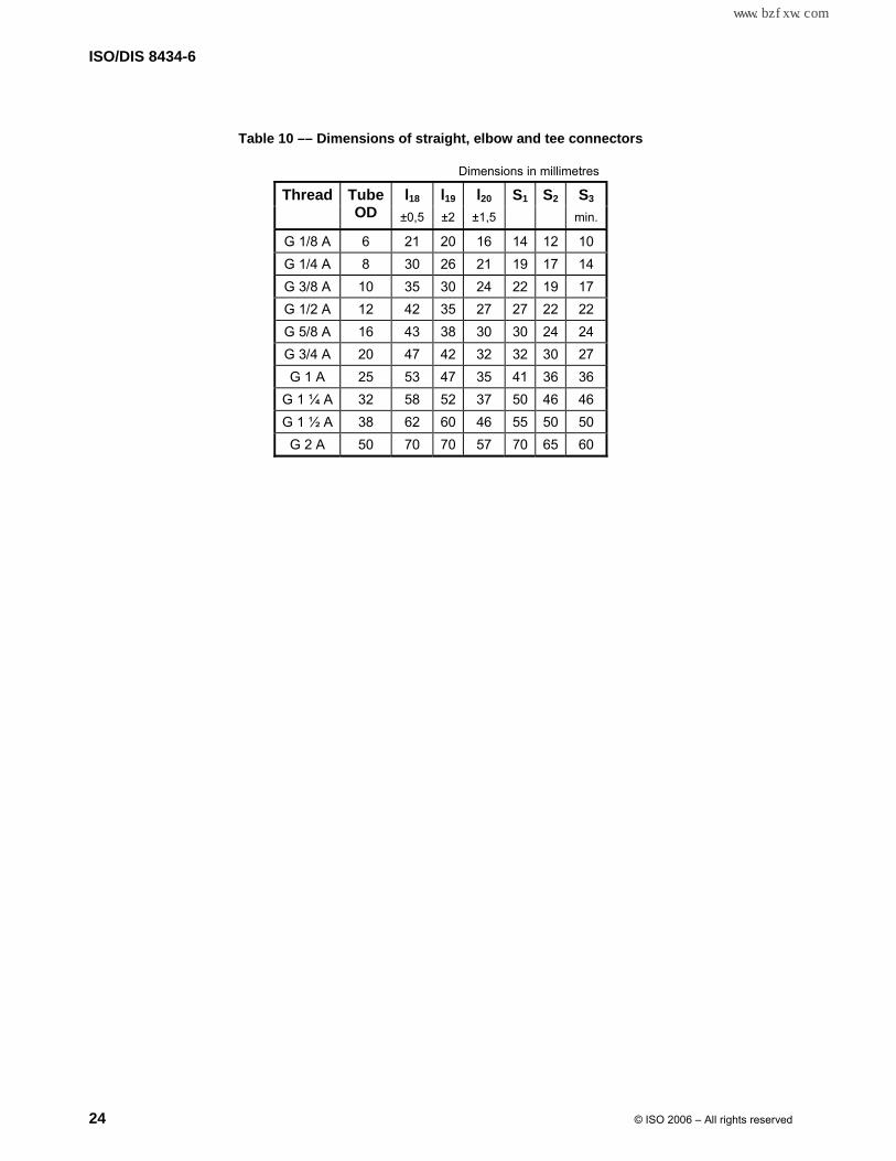
Table 10 –– Dimensions of straight, elbow and tee connectors
Dimensions in millimetres
l18 l19 l20 S1 S2 S3 Thread Tube OD ±0,5 ±2 ±1,5 min.
G 1/8 A 6 21 20 16 14 12 10 G 1/4 A 8 30 26 21 19 17 14 G 3/8 A 10 35 30 24 22 19 17 G 1/2 A 12 42 35 27 27 22 22 G 5/8 A 16 43 38 30 30 24 24 G 3/4 A 20 47 42 32 32 30 27 G 1 A 25 53 47 35 41 36 36
G 1 ¼ A 32 58 52 37 50 46 46 G 1 ½ A 38 62 60 46 55 50 50 G 2 A 50 70 70 57 70 65 60
标准分享网 www.bzfxw.com 免费下载

ISO/DIS 8434-6
© ISO 2006 – All rights reserved 25
NOTE 1 This connector may also be used as a stud connector in association with bonded washer type seals. For rated pressure, consult manufacturer. NOTE 2 The undercut shown by Figure 34 and Table 22 is preferred for bonded washer type seals. NOTE 3 S2 optional hex size is not suitable for bonded washer type seals. a For details, see Figure 2 and Table 3. b For details, see Figure 3 or 4 and Table 3.
Figure 13 — Straight swivel connector (SWS)

ISO/DIS 8434-6
26 © ISO 2006 – All rights reserved
a For details, see Figure 2 and Table 3. b For details, see Figure 3 or 4 and Table 3.
a For details, see Figure 2 and Table 3. b For details, see Figure 3 or 4 and Table 3.
Figure 14 — 90° swivel elbow connector (SWE) Figure 15 — 45° swivel elbow connector (SWE45)
S3 across flats
S3 across flats
a a
bb
标准分享网 www.bzfxw.com 免费下载

ISO/DIS 8434-6
© ISO 2006 – All rights reserved 27
Table 11 –– Dimensions of swivel connectors
Thread Tube OD
l19 l20 l21 l22 l49 S1 S2 S3
±2 ±2 ±2 ±2 ±0,50 min.
G 1/8 A 6 20 16 20 16 22 14 12 10 G 1/4 A 8 26 21 26 21 31 19 17 14 G 3/8 A 10 30 24 30 25 35 22 19 17 G 1/2 A 12 35 27 35 29 41 27 22 22 G 5/8 A 16 38 30 38 30 42 30 24 24 G 3/4 A 20 42 32 42 30 45 32 30 27 G 1 A 25 47 35 44 32 51 41 36 36
G 1 ¼ A 32 52 37 49 34 55 50 46 46 G 1 ½ A 38 60 46 61 47 64 55 50 50 G 2 A 50 70 57 68 55 69 70 65 60

ISO/DIS 8434-6
28 © ISO 2006 – All rights reserved
a For details of stud end and undercut for O-ring, see ISO 6149-3. b For details, see Figure 2 and Table 3.
Figure 16 –– Straight stud connector (SDS)
a For details of stud end and undercut for O-ring, see ISO 6149-3. b For details, see Figure 3 or 4 and Table 3.
Figure 17 –– Straight stud swivel connector with ISO 6149-3 stud end (SWSDS)
S4 across flats
a b
S4 across flats
a b
标准分享网 www.bzfxw.com 免费下载

ISO/DIS 8434-6
© ISO 2006 – All rights reserved 29
Table 12 –– Dimensions of straight stud swivel connectors with ISO 6149-3 stud ends
Dimensions in millimetres
Thread l23 l24 l25 l26 S4
60° cone end ISO 6149-3 end Tube OD ± 0,5 ref. ± 0,5 ref. min.
G 1/8 A M10 × 1 6 24,0 15,5 24,5 16,0 14
G 1/4 A M14 × 1,5 8 31,5 20,5 31,9 20,9 19
G 3/8 A M16 × 1,5 10 34,0 22,5 33,8 22,3 22
G 1/2 A M18 × 1,5 12 38,0 25,5 37,7 25,2 24
G 5/8 A M22 × 1,5 16 41,5 28,5 38,3 25,3 27
G 3/4 A M27 × 2 20 44,5 28,5 42,7 26,7 32
G 1 A M33 × 2 25 52,0 36,0 48,7 32,7 41
G 1 ¼ A M42 × 2 32 55,0 39,0 52,1 36,1 50
G 1 ½ A M48 × 2 38 59,5 42,0 60,1 42,6 55
G 2 A M60 × 2 50 63,5 46,0 61,4 43,9 65 NOTE These connectors are suitable for assembly with ports in accordance with ISO 6149-1.

ISO/DIS 8434-6
30 © ISO 2006 – All rights reserved
a For details, see Figure 2 and Table 3. b For details of adjustable end, see ISO 6149-3.
Figure 18 –– 90° adjustable stud elbow connector (SDE)
a For details, see Figure 2 and Table 3. b For details of adjustable end, see ISO 6149-3.
Figure 19 –– 45° adjustable stud elbow connector with ISO 6149-3 adjustable stud end (SDE45)
S3 across flats
a
b
S3 across flats
a
b
标准分享网 www.bzfxw.com 免费下载

ISO/DIS 8434-6
© ISO 2006 – All rights reserved 31
Table 13 –– Dimensions of stud elbow connectors with ISO 6149-3 adjustable stud ends
Dimensions in millimetres
Thread l19 l20 l27 l28 l29 l30 S3
60° cone end ISO 6149-3 end Tube OD ± 2 ± 2 ± 2 ref. ± 2 ref. min.
G 1/8 A M10 × 1 6 20 16 30 17,4 26 28,7 10
G 1/4 A M14 × 1,5 8 26 21 37 23,9 32 35,7 14
G 3/8 A M16 × 1,5 10 30 24 40 24,4 34 39,4 17
G 1/2 A M18 × 1,5 12 35 27 42 27,2 36 42,5 22
G 5/8 A M22 × 1,5 16 38 30 46 30,2 38 46,4 24
G 3/4 A M27 × 2 20 42 32 55 31,7 45 51,8 27
G 1 A M33 × 2 25 47 35 57 36,2 45 53,9 36
G 1 ¼ A M42 × 2 32 52 37 61 40,2 46 56,4 46
G 1 ½ A M48 × 2 38 60 46 69 50,7 55 70,2 50
G 2 A M60 × 2 50 70 57 76 58,7 63 86,0 60 NOTE These connectors are suitable for assembly with ports in accordance with ISO 6149-1.

ISO/DIS 8434-6
32 © ISO 2006 – All rights reserved
a For details of adjustable end, see ISO 6149-3. b For details, see Figure 3 or 4 and Table 3.
Figure 20 –– 90° swivel adjustable stud elbow connector with ISO 6149-3 adjustable stud end (SWSDE)
a For details of adjustable end, see ISO 6149-3. b For details, see Figure 3 or 4 and Table 3.
Figure 21 –– 45° swivel adjustable stud elbow connector with ISO 6149-3 adjustable stud end (SWSDE45)
S3 across flats
a
b
S3 across flats
a
b
标准分享网 www.bzfxw.com 免费下载

ISO/DIS 8434-6
© ISO 2006 – All rights reserved 33
Table 14 –– Dimensions of swivel elbow connectors with ISO 6149-3 adjustable stud ends
Dimensions in millimetres
Thread l21 l22 l27 l28 l29 l31 S3
60° cone end ISO 6149-3 end Tube OD ± 2 ± 2 ± 2 ref. ± 2 ref. min.
G 1/8 A M10 × 1 6 20 16 30 17,4 26 28,7 10
G 1/4 A M14 × 1,5 8 26 21 37 23,9 32 35,7 14
G 3/8 A M16 × 1,5 10 30 25 40 24,4 34 40,1 17
G 1/2 A M18 × 1,5 12 35 29 42 27,2 36 43,9 22
G 5/8 A M22 × 1,5 16 38 30 46 30,2 38 46,4 24
G 3/4 A M27 × 2 20 42 30 55 31,7 45 50,4 27
G 1 A M33 × 2 25 44 32 57 36,2 45 51,8 36
G 1 ¼ A M42 × 2 32 49 34 61 40,2 46 54,2 46
G 1 ½ A M48 × 2 38 61 47 69 50,7 55 70,9 50
G 2 A M60 × 2 50 68 55 76 58,7 63 84,6 60 NOTE These connectors are suitable for assembly with ports in accordance with ISO 6149-1.

ISO/DIS 8434-6
34 © ISO 2006 – All rights reserved
a For details of stud end and undercut for seal, see ISO 1179-2. b For details, see Figure 2 and Table 3.
Figure 22 –– Straight stud connector with ISO 1179-2 type E stud end (L series) (SDS)
a For details of stud end and undercut for seal, see ISO 1179-2. b For details, see Figure 3 or 4 and Table 3.
Figure 23 –– Straight stud swivel connector with ISO 1179-2 type E stud end (L series) (SWSDS)
Table 15 –– Dimensions of stud connectors with ISO 1179-2 type E stud ends (L series)
Dimensions in millimetres
Thread l32 l33 l34 l35
60° cone end ISO 1179-2 end Tube OD ± 0,5 ref. ± 0,5 ref.
S5
G 1/8 A G 1/8 A 6 22,5 14,5 23,0 15,0 14 G 1/4 A G 1/4 A 8 32,0 20,0 32,4 20,4 19 G 3/8 A G 3/8 A 10 34,5 22,5 34,3 22,3 22 G 1/2 A G 1/2 A 12 41,0 27,0 40,7 26,7 27 G 3/4 A G 3/4 A 20 47,0 31,0 45,2 29,2 32 G 1 A G 1 A 25 54,0 36,0 50,7 32,7 41
G 1 ¼ A G 1 ¼ A 32 59,0 39,0 56,1 36,1 50 G 1 ½ A G 1 ½ A 38 64,0 42,0 64,6 42,6 55
NOTE These connectors are suitable for assembly with ports in accordance with ISO 1179-1.
S5 across flats
S5 across flats
a
a
b
b
标准分享网 www.bzfxw.com 免费下载

ISO/DIS 8434-6
© ISO 2006 – All rights reserved 35
a For details of stud end and undercut for O-ring, see ISO 1179-3. b For details, see Figure 2 and Table 3.
Figure 24 –– Straight stud connector with ISO 1179-3 type G stud end (SDS)
a For details of stud end and undercut for O-ring, see ISO 1179-3. b For details, see Figure 3 or 4 and Table 3.
Figure 25 –– Straight stud swivel connector with ISO 1179-3 type G stud end (SWSDS)
Table 16 –– Dimensions of stud connectors with ISO 1179-3 type G stud ends Dimensions in millimetres
Thread l36 l37 l38 l39
60° cone end ISO 1179-3 end Tube OD ± 0,5 ref. ± 0,5 ref.
S5
G 1/8 A G 1/8 A 6 20,6 14,4 21,1 14,9 14 G 1/4 A G 1/4 A 8 29,2 19,9 29,6 20,3 19 G 3/8 A G 3/8 A 10 31,2 21,9 31,0 21,7 22 G 1/2 A G 1/2 A 12 38,4 25,9 38,1 25,6 27 G 3/4 A G 3/4 A 20 42,4 29,9 40,6 28,1 32 G 1 A G 1 A 25 51,5 35,6 48,2 32,3 41
G 1 ¼ A G 1 ¼ A 32 54,5 38,6 51,6 35,7 50 G 1 ½ A G 1 ½ A 38 57,5 41,6 58,1 42,2 55
NOTE These connectors are suitable for assembly with ports in accordance with ISO 1179-1.
S5 across flats
S5 across flats
a
a
b
b

ISO/DIS 8434-6
36 © ISO 2006 – All rights reserved
a For details, see Figure 2 and Table 3. b For details of adjustable end, see ISO 1179-3.
Figure 26 –– 90° adjustable stud elbow connector with ISO 1179-3 type H stud end (SDE)
a For details, see Figure 2 and Table 3. b For details of adjustable end, see ISO 1179-3.
Figure 27 –– 45° adjustable stud elbow connector with ISO 1179-3 type H stud end (SDE45)
S3 across flats
S3 across flats
a
a
b
b
标准分享网 www.bzfxw.com 免费下载

ISO/DIS 8434-6
© ISO 2006 – All rights reserved 37
Table 17 –– Dimensions of adjustable stud elbow connectors with ISO 1179-3 type H stud ends
Dimensions in millimetres
Thread l19 l20 l40 l41 l42 l43 S3
60° cone end ISO 1179-3 end Tube OD ± 2 ± 2 ± 2 ref. ± 2 ref. min.
G 1/8 A G 1/8 A 6 20 16 26 17,5 26 28,8 10 G 1/4 A G 1/4 A 8 26 21 35 23,8 32 35,4 14 G 3/8 A G 3/8 A 10 30 24 36 24,9 34 39,9 17 G 1/2 A G 1/2 A 12 35 27 43 28,2 41 45,2 22 G 3/4 A G 3/4 A 20 42 32 47 31,6 44 51,7 27 G 1 A G 1 A 25 47 35 54 36,2 48 55,4 36
G 1 ¼ A G 1 ¼ A 32 52 37 59 41,7 49 57,9 46 G 1 ½ A G 1 ½ A 38 60 46 70 51,9 56 71,2 50
NOTE These connectors are suitable for assembly with ports in accordance with ISO 1179-1.

ISO/DIS 8434-6
38 © ISO 2006 – All rights reserved
a For details of adjustable end, see ISO 1179-3. b For details, see Figure 3 or 4 and Table 3.
Figure 28 –– 90° swivel adjustable stud elbow connector with ISO 1179-3 type H stud end (SWSDE)
a For details of adjustable end, see ISO 1179-3. b For details, see Figure 3 or 4 and Table 3.
Figure 29 –– 45° swivel adjustable stud elbow connector with ISO 1179-3 type H stud end (SWSDE45)
S3 across flats
S3 across flats
a
a
b
b
标准分享网 www.bzfxw.com 免费下载

ISO/DIS 8434-6
© ISO 2006 – All rights reserved 39
Table 18 –– Dimensions of swivel adjustable elbow connectors with ISO 1179-3 type G stud ends
Dimensions in millimetres
Thread l21 l22 l40 l41 l42 l44 S3
60° cone end ISO 1179-3 end Tube OD ± 2 ± 2 ± 2 ref. ± 2 ref. min.
G 1/8 A G 1/8 A 6 20 21,0 26 17,5 26 34,0 10 G 1/4 A G 1/4 A 8 26 22,0 35 23,8 32 36,5 14 G 3/8 A G 3/8 A 10 30 25,5 36 24,9 34 40,5 17 G 1/2 A G 1/2 A 12 35 29,0 43 28,2 41 46,0 22 G 3/4 A G 3/4 A 20 42 34,5 47 31,6 44 53,5 27 G 1 A G 1 A 25 44 38,0 54 36,2 48 58,0 36
G 1 ¼ A G 1 ¼ A 32 49 39,0 59 41,7 49 59,5 46 G 1 ½ A G 1 ½ A 38 61 44,0 70 51,9 56 70,5 50
NOTE These connectors are suitable for assembly with ports in accordance with ISO 1179-1.

ISO/DIS 8434-6
40 © ISO 2006 – All rights reserved
a For details, see Figure 3 or 4 and Table 3. b For details, see Figure 2.
a For details, see Figure 2 and Table 3. b For details, see Figure 3 or 4 and Table 3.
Figure 30 –– Swivel branch tee connector (SWBT) Figure 31 –– Swivel run tee connector (SWRT)
Table 19 –– Dimensions of swivel tee connectors
Dimensions in millimetres
l19 l21 S3 Thread Tube OD ± 2 ± 2 min.
G 1/8 A 6 20 20 10 G 1/4 A 8 26 20 14 G 3/8 A 10 30 30 17 G 1/2 A 12 35 35 22 G 5/8 A 16 38 38 24 G 3/4 A 20 42 44 27 G 1 A 25 47 49 36
G 1 ¼ A 32 52 54 46 G 1 ½ A 38 60 58 50 G 2 A 50 64 62 60
S3 across flats S3 across flats
a a
bb
标准分享网 www.bzfxw.com 免费下载

ISO/DIS 8434-6
© ISO 2006 – All rights reserved 41
Key 1 12 mm maximum bulkhead thickness
a For details, see Figure 2. b For details, see Figure 2, except for thread length.
Figure 32 –– Straight bulkhead connector (BHS)
Table 20 –– Dimensions of straight bulkhead connectors
l45 l46 l50 S6 Thread Tube OD ± 0,25 ± 0,25 ± 0,5 min.
G 1/8 A 6 25 5 38 14 G 1/4 A 8 29 6 47 19 G 3/8 A 10 31 7 52 22 G 1/2 A 12 34 8 60 27 G 5/8 A 16 37 9 64 30 G 3/4 A 20 37 9 66 32 G 1 A 25 41 10 74 41
G 1 ¼ A 32 45 13 81 50 G 1 ½ A 38 49 15 88 55 G 2 A 50 52 15 95 70

ISO/DIS 8434-6
42 © ISO 2006 – All rights reserved
Key 1 12 mm maximum bulkhead thickness 2 Locknut a For details, see Figure 2 and Table 3. b For details, see Figure 2, except for thread length, and Table 3.
Figure 33 –– 90° bulkhead elbow connector (BHE)
Table 21 –– Dimensions of 90° bulkhead elbow connectors
Dimensions in millimetres
l19 l45 l46 l47 S3 Thread Tube OD ± 2 ± 0,25 ± 0,25 ± 2 min.
S6
G 1/8 A 6 20 25 5 37 10 14G 1/4 A 8 26 29 6 44 14 19G 3/8 A 10 30 31 7 49 17 22G 1/2 A 12 35 34 8 55 22 27G 5/8 A 16 38 37 9 59 24 30G 3/4 A 20 42 37 9 63 27 32G 1 A 25 47 41 10 69 36 41
G 1 ¼ A 32 52 45 13 77 46 50G 1 ½ A 38 60 49 15 87 50 55G 2 A 50 64 52 15 97 60 70
1
S3 across flats
a
b
S6 across flats
2
标准分享网 www.bzfxw.com 免费下载

ISO/DIS 8434-6
© ISO 2006 – All rights reserved 43
Surface roughness in micrometres
Key 1 Major diameter of thread
Figure 34 –– Preferred thread undercut details when bonded washer type seal is used
Table 22 –– Preferred thread undercuts for 60° cone male connectors when used as stud connectors with bonded washer type seals
Dimensions in millimetres
d23 l48 r Thread Tube OD
d22
± 0,15 ± 0,25 ± 0,1
8,25 G 1/8 A 6
8,00 9,0 2,54 0,50
11,18G 1/4 A 8
10,9213,0 3,81 0,76
14,60G 3/8 A 10
14,3016,5 3,81 0,76
18,29G 1/2 A 12
17,9820,8 4,82 1,0
20,19G 5/8 A 16
19,8922,7 4,82 1,0
23,75G 3/4 A 20
23,4226,2 4,82 1,0
29,97G 1 A 25
29,5933,0 5,84 1,0
38,61G 1 ¼ A 32
38,2341,7 5,84 1,0
44,45G 1 ½ A 38
44,0747,6 5,84 1,0
56,26G 2 A 50
55,8859,4 5,84 1,0
1

ISO/DIS 8434-6
44 © ISO 2006 – All rights reserved
Bibliography
[1] ISO 228-2, Pipe threads where pressure tight joints are not made on the threads — Part 2: Verification by means of limit gauges.
[2] ISO 286-1, ISO system of limits and fits — Part 1: Bases of tolerances, deviations and fits.
[3] ISO 286-2, ISO system of limits and fits — Part 2: Tables of standard tolerance grades and limit deviations for holes and shafts.
[4] ISO 468, Surface roughness — Parameters, their values and general rules for specifying requirements.
[5] ISO 1179-41), Connections for general use and fluid power — Ports and stud ends with ISO 228-1 threads with elastomeric or metal-to-metal sealing — Part 4: Stud ends for general use only with metal-to-metal sealing (type B)
[6] ISO 4397, Fluid power systems and components — Connectors and associated components — Outside diameters of tubes and nominal inside diameters of hoses
[7] ISO 6149-2, Connections for fluid power and general use — Ports and stud ends with ISO 261 threads and O-ring sealing — Part 2: Dimensions, design, test methods and requirements for heavy-duty (S series) stud ends
1) To be published.
标准分享网 www.bzfxw.com 免费下载