Merganser Duck Trap - Calvin College · PDF fileMerganser Duck Trap Final Design Proposal...
58
Merganser Duck Trap Final Design Proposal Calvin College Engineering 340 May 12, 2006 Team Two: Duck Hunt Ashley Baker Ann Nieuwkoop Chad Nyenhuis
-
Upload
truongdung -
Category
Documents
-
view
219 -
download
1
Transcript of Merganser Duck Trap - Calvin College · PDF fileMerganser Duck Trap Final Design Proposal...
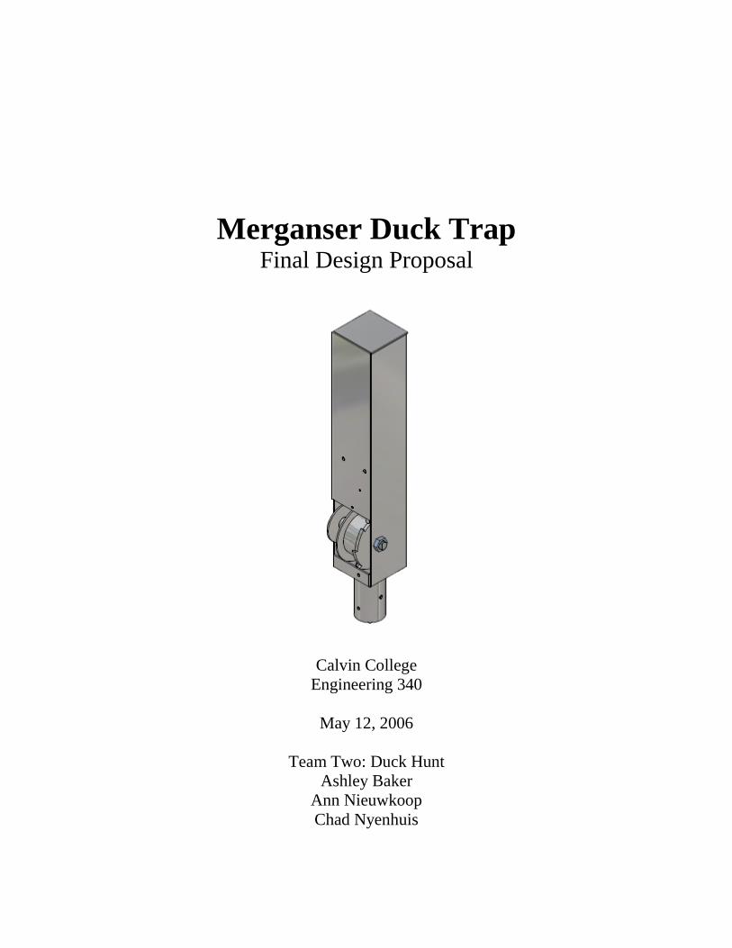
Merganser Duck Trap Final Design Proposal
Calvin College
Engineering 340
May 12, 2006
Team Two: Duck Hunt
Ashley Baker
Ann Nieuwkoop
Chad Nyenhuis

© 2006 Calvin College and Ashley Baker, Ann Nieuwkoop, and Chad Nyenhuis
Executive Summary
This report summarizes the Senior Design project of Team 2: Duck Hunt. The
team members include Ashley Baker, Ann Nieuwkoop, and Chad Nyenhuis. The main
goal of this project was to design and build a device to capture Common Merganser
ducks for medical treatment of a parasite that causes swimmer’s itch. This project was
done in conjunction with SICon, L.L.C., a company focused on the research and control
of swimmer’s itch. This project provides SICon with a more efficient method of
capturing Common Merganser ducks than their current method and will therefore aid in
the control of swimmer’s itch on affected lakes. The main issues SICon was concerned
with include net visibility, remote activation, and adaptability.
A final working prototype, a user’s manual, a parts list, and this final design
report were completed. The final working prototype design consists of four poles that are
set up in a lake. A net that is initially underwater is connected to each pole. When the
trap is triggered, a spring-loaded mechanism pulls the nets vertically out of the water and
traps the ducks in an enclosed area. The final cost of this prototype is $528.04 and the
prototype will be given to SICon for their use in capturing Common Merganser ducks to
control swimmer’s itch.
Table of Contents
1. Introduction ................................................................................................................... 7
1.1. Background Information ......................................................................................... 7
1.2. Project Overview .................................................................................................... 7
2. Problem Specification ................................................................................................... 8
2.1. Problem Description ............................................................................................... 8
2.1.1. Current Method .............................................................................................. 8
2.1.2. Current Problems ........................................................................................... 8
2.2. Project Requirements .............................................................................................. 8
2.2.1. Weight ............................................................................................................ 9
2.2.2. Size ................................................................................................................. 9
2.2.3. Setup .............................................................................................................. 9
2.2.4. Material .......................................................................................................... 9
2.2.5. Performance ................................................................................................... 9
2.2.6. Course ............................................................................................................ 9
3. Design Norms ............................................................................................................. 10
4. Proposed Solution ....................................................................................................... 11
4.1. Research ................................................................................................................ 11
4.2. Design Decisions .................................................................................................. 11
4.3. Trap Design ........................................................................................................... 13
4.3.1. Design Decisions ......................................................................................... 13
4.3.2. Setup ............................................................................................................ 13
4.3.3. Structure ....................................................................................................... 13
4.3.4. Trigger Mechanism ...................................................................................... 14
4.3.5. Electrical Components ................................................................................. 14
4.4. Testing and Modifications .................................................................................... 15
4.4.1. Basic Design and Spring Force Test ............................................................ 16
4.4.2. Spring Test ................................................................................................... 16
4.4.3. Working Prototype Test ............................................................................... 16
4.4.4. Modified Prototype Test .............................................................................. 16
5. Project Management ................................................................................................... 17
5.1. Team Organization................................................................................................ 17
5.2. Work Breakdown Structure .................................................................................. 17
5.3. Schedule ................................................................................................................ 18
5.4. Budget ................................................................................................................... 18
6. Conclusion .................................................................................................................. 21
6.1. Lessons Learned.................................................................................................... 21
6.2. What We Would Have Done Differently.............................................................. 21
6.3. Future Work .......................................................................................................... 22
7. Acknowledgements ..................................................................................................... 22
Appendices
Appendix A: User’s Manual
Appendix B: Design Alternatives
Appendix C: Design Development
Appendix D: Finite Element Analysis
Appendix E: Component Drawings
Appendix F: Assembly Drawings
Figures and Tables
Figure 1: Block Diagram
Table 1: Budget Report and Parts List
Figure A.1: Trap Components
Figure A.2: Feed Cable through Base of Housing
Figure A.3: Attach Spring to Quick-Clip
Figure A.4: Feed Spring into Pole
Figure A.5: Slide Pole into Collar on Housing
Figure A.6: Tighten Thumb Screws
Figure A.7: Feed the Long Hook in the Pole
Figure A.8: Extend the Spring by Pulling Down on the Long Hook
Figure A.9: Feed the Bolt through the End of the Spring
Figure A.10: Insert the Auger into the Pole
Figure A.11: Insert the Bolt through the Auger
Figure A.12: Insert the Collar and Spacer on Bolt
Figure A.13: Feed the Bolt through the Pipe
Figure A.14: Insert the Collar and Spacer on Bolt
Figure A.15: Screw Bolt into Collar
Figure A.16: Turning on the Receiver
Figure A.17: Turning in the Poles
Figure A.18: All Four Poles Set
Figure A.19: Laying Out the Net
Figure A.20: Attaching the Net
Figure A.21: Attaching the Lead Line
Figure A.22: Hanging the Net
Figure A.23: Submerging the Net
Figure A.24: Pressing the Button
Figure A.25: Net Springing Upward
Figure B.1: Alternative One – Duck and Trap Layout
Figure B.2: Alternative One – Wheel Device – Top View
Figure B.3: Alternative Two – Dock and Trap Layout
Figure B.4: Alternative Four – Retractable Poles With Net
Figure B.5: Initial Setup of Preliminary Design
Figure B.6: Preliminary Design Mechanism
Figure B.7: Final Setup of Preliminary Design
Figure B.8: Electrical Block Diagram

Figure C.1: Original Pulley Design
Figure C.2: Ratchet System: The First Locking Mechanism
Figure C.3: Two-Part Lever Arm Locking Pin Design
Figure C.4: Front View of Locking Pin Mechanism
Figure C.5: Rear View of the Locking Pin Mechanism
Figure C.6: New Z-Shaped Swiveling Lever Arm and Triggering Mechanism
Figure C.7: The Final Design: Internal Triggering Mechanism
Figure D.1: Stress Calculations for the Locking Pin
Figure D.2: Deflection Calculations for the Locking Pin
Figure D.3: Stress Calculations for the Gear Tooth
Figure D.4: Deflection Calculations for the Gear Tooth
Figure D.5: Stress Calculations for the Trap Pole
Figure D.6: Deflection Calculations for the Trap Pole
Figure D.7: Stress Calculations for the Housing
Figure D.8: Deflection Calculations for the Housing
7
1. Introduction
1.1. Background Information
Schistosome cercarial dermatitis, commonly known as swimmer’s itch, is a
reaction people have to a parasite entering the top layer of their skin. The larval stage
of this parasite lives in snails, while the adult stage of this parasite lives in birds,
typically Common Merganser ducks. Swimmer’s itch is due to the larval stage of the
parasite accidentally entering the skin of an unsuspecting swimmer instead of a bird
host. Symptoms of swimmer’s itch include an itchy red rash that can last for up to a
week. Swimmer’s itch is a common problem in northern Michigan lakes, as well as
other northern states and other parts of the world.
In the past, the state of Michigan has treated swimmer’s itch in northern
Michigan lakes primarily by depositing chemicals into the lakes to kill the snail hosts.
The long-term effects of this control method are unknown. SICon has found that
treating the duck hosts with a medicine that kills the parasites is an effective and
environmentally safe method of controlling swimmer’s itch on northern Michigan
lakes.
1.2. Project Overview
The purpose of our senior design project was to design and build an efficient
device to trap Common Merganser ducks for medical treatment and further research
of swimmer’s itch. Once the ducks are trapped, they will be treated for the parasites
that cause swimmer’s itch and released back into their natural environment unharmed.
This process will help control swimmer’s itch by eliminating only the parasites that
cause swimmer’s itch and not harming the ducks or the lake environment. The
deliverables of this project include a working prototype, a user’s manual, a parts list,
and this final design report.
8
2. Problem Specification
2.1. Problem Description
2.1.1. Current Method
SICon’s current method of trapping the ducks is to chase them into the
open end of a stationary, V-shaped net. Two sides of the net are hidden
underwater, while the third side is approximately three feet above the water and
visible to the ducks. The sides of the net are pulled up from under the water by
two people on shore. The open end is then blocked by people to ensure that the
ducks do not escape, while other people catch the ducks and give them a pill to
kill the parasites. The ducks must be trapped and treated twice a year to eliminate
the parasites.
2.1.2. Current Problems
One problem SICon has with their current trapping method is that the
ducks begin to catch on to the trapping method. This makes the ducks difficult to
catch a second time because the ducks can see the net above water and will avoid
it.
Another problem SICon has with their current trapping method is that it is
not versatile enough to be positioned at various locations around a lake. SICon
has found that Common Merganser ducks usually stay nears certain boat docks.
There is great potential for trapping the ducks while they are in this area.
However, the current trapping system would not work to be positioned around a
dock.
Finally, their current trap is not fully enclosed. In order to trap the ducks,
people must be close enough to block the open end of the trap. This requires
more people to trap the ducks and increases the likelihood of the ducks being
scared away.
2.2. Project Requirements
From the problems SICon had with their current trapping method, we
developed a set of design requirements we wanted to meet with our new trap.
9
These requirements related to the design of the trap and also to the overall Senior
Design course.
2.2.1. Weight
The weight of the trap shall be minimal to ensure portability
The weight of the trap shall be minimal to ensure that an adult can carry
one pole
2.2.2. Size
The trap components shall be as small as possible to ensure portability
The trap shall be no larger than 25 feet by 25 feet to ensure that the ducks
will not be able to begin flight
2.2.3. Setup
The entire device shall be able to be set up by no more than two people
The set up time shall not exceed 15 minutes
Once the trap has been triggered, it shall be able to be reset in less than
five minutes
The trap shall be adjustable to be set up in multiple areas near the shore
and in various water depths
2.2.4. Material
All materials shall be durable and corrosion resistant in order to withstand
relocation and the lake environment
All materials shall be water resistant and/or waterproof
2.2.5. Performance
The trap shall be able to trap ducks that dive below the water
The trap shall not harm the ducks
The trap shall be activated by a remote trigger
2.2.6. Course
The team shall work together effectively
The team shall complete all course requirements on time

10
One focus of the team shall be on learning about engineering design and
production in a real-world scenario
One focus of the team shall be on learning about design from a Christian
perspective
3. Design Norms
In product design, there are certain guidelines or design norms that Christian
engineers must consider. The design norms that directly relate to our project are
stewardship, caring, cultural appropriateness, transparency, trust.
Stewardship is important for our project because our project will provide an
environmentally safe method of controlling swimmer’s itch. In the past, the state of
Michigan deposited chemicals in lakes affected by swimmer’s itch to kill the snails that
hosted the parasites. The long-term consequences of this control method are unknown.
Our project will aid in controlling swimmer’s itch without harming the ducks or the lake
environment.
Another design norm that affects our project is caring. Our project will not injure
the ducks or the lake environment; it will only trap the ducks in order to treat them for the
parasites. Our project will also help people enjoy the lakes safely. Children are more
susceptible to swimmer’s itch than adults. Our project will protect children who swim in
affected lakes and also relieve parents from treating their children from swimmer’s itch
as frequently.
Cultural appropriateness is another design norm that is important to our project.
SICon expressed that Common Mergansers are very intelligent ducks and that they can
recognize things that do not fit into their ordinary lake environment. Since our trap has
four poles that are visible to the ducks, we designed them to look like dock poles.
Therefore, the trap will blend into the lake environment.
In the process of designing our project, we also considered transparency.
Throughout the project, transparency was achieved through open communication with
SICon and complete documentation of meetings, information, and tests. Also, it is
important that our trap can be setup quickly and without much difficultly. Our design is
simple, so that it will be as easy to set up and use as possible. It will require minimal

11
training and skill to use and operate. The final product includes a user’s manual and parts
list to help others understand how to use, maintain, and repair the trap.
The final design norm we considered was trust. The final design is dependable
and made of durable materials specific to the lake environment in order to reduce wear
and corrosion. All parts used to construct our final design are available from many
different manufacturers for easy replacement. The trapping process is repeatable. It can
take three to four hours to guide the ducks into the trap area, so it is very important that
the trap works every time.
4. Proposed Solution
4.1. Research
Before we began designing, we researched our client’s needs and swimmer’s
itch. We spoke with SICon several times to make sure we understood their
problems with their current trap and the improvements they wanted to see in our
trap. We also researched swimmer’s itch and how it is transmitted by Merganser
ducks.
4.2. Design Decisions
Throughout the course, we made several decisions regarding significant
features and components. The design alternatives initially considered in this project
can be found in Appendix B. The first major decision made was between stationary
poles with a moving net or retractable poles where both the poles and the net
moved. After first learning about the problems SICon was experiencing with their
current trap, we thought the entire trap should be submerged below water.
However, after further discussion with SICon, we found that the net was the most
important thing to hide and that we would be able to disguise the poles as dock
poles. SICon had found in the past that by using a hidden net, it was much easier to
trap the ducks. So, we decided to design our trap using stationary poles and
disguise them to fit into the surrounding lake environment so that they don’t scare
away the ducks.
The next design decision we encountered was what type of material to make
the trap out of. Steel was initially considered because it is easy to weld and readily
12
available. However, aluminum was chosen as the primary material for the trap for
several reasons. Aluminum is lightweight and would allow for easy transport.
Also, aluminum is corrosion resistant, making it a great choice for the lake
environment. Finally, using aluminum would aide in disguising the poles as = dock
poles commonly found in the lake.
After we decided on the type of material for the poles, we considered the
shape of the pole. We had the choice between square or round poles. Our initial
design was to use square poles because it would be easier to mount a mechanism
onto a flat surface and our pulley system would also fit better. However, we
decided to use round poles because they are easier to screw into the lake using
augers. It was then decided that we would mount a square housing on the top of the
pole to solve the problem of attaching a mechanism to a round surface. Also, a
Finite Element Analysis (FEA) showed that round poles were stronger than square
poles. More information on FEA can be found in Appendix D.
Another major design decision was whether to use a spring or a compressed
air cylinder to pull the nets out of the water. Compressed air cylinders were
reviewed because they had very controlled strokes and could be triggered easily.
However, air cylinders included the inconvenience of having to recharge the
cylinders with air after each firing. Another problem with air cylinders was the
introduction of possible failure. Because the trap will be used in a lake
environment, water could possibly leak in and ruin them, leaving the trap useless.
Also, springs are less expensive, available at most hardware or home improvement
store, and were more adjustable for different situations.
The next design decision was how to use the spring to lift the net out of the
water four feet. Our first idea was to use a spring that would stretch the entire
length of the pole combined with a single pulley. The problem with this idea was
that the spring would not be able to pull the nets up the necessary distance. This
forced us look at different methods of getting the net to travel two or three times as
far as the spring length. A two-stage pulley system was developed with a diameter
ratio of 3.5 to 1. This system would allow the net to travel seven feet for every two
feet the spring traveled.

13
Different types of springs were researched. We looked into using a clock
spring, similar to the action of a seat belt. This idea looked very promising at first
because it didn’t require making a pulley system and it kept the entire spring inside
the cylinder that the cable would wrap around. However, we found that high force
clock springs were not available for winding up seven feet of cable. The highest
force we found was around 15 pounds which was far to low for our application.
After testing other types of springs, we chose garage door springs.
Several times we had to decide between building and buying our parts. We
decided to fabricate many of our parts in our shop because this project is very
specialized and will not be massed produced. Even though this would be costly to
machine each part special, we would not be able to receive large cost reductions for
having our parts manufactured.
4.3. Trap Design
4.3.1. Design Decisions
4.3.2. Setup
The trap can be set up by two people in approximately fifteen minutes.
The trap is designed to be set up in one to three feet of water with a sandy lake
bottom. Methods are provided to adjust the trap based on water depth. Refer to
the user’s manual in Appendix A for full setup instructions.
4.3.3. Structure
The frame of the trap is four nine foot aluminum poles. They are screwed
into the lake bottom using augers. A PVC frame was considered in cases where
the augers would not be able to screw into the lake bottom. However, based on
SICon’s specifications and our research, we found that Merganser ducks typically
only spend time in areas with sandy lake bottoms. Therefore, since the trap would
only be set up in these areas, we did not design a frame structure.
Strung between each pole is a lead-lined, nylon net. The nets are attached
to a cable via quick-clips, which are then attached to a two inch ring. This ring
runs up and down a cable guide that is mounted onto the outside of each pole.
14
The cable guide ensures that the nets rise vertically out of the water after
triggering of the trap.
4.3.4. Trigger Mechanism
Note that the trigger mechanism described is duplicated for all four poles.
Inside the pole is a ninety pound garage door spring which is initially extended
two feet. This spring is attached to another cable via a quick-clip. To secure the
spring, a bolt is inserted through the side of the pole. The other end of this cable
winds around a one inch diameter pulley. Fixed to this pulley is a three and a half
inch diameter pulley around which the cable attached to the net winds. Because
of this one to three and a half pulley ratio, for every foot the spring extends, the
net is able to pulled up three and a half feet. Therefore, when the spring is
extended two feet, the net will travel seven feet, allowing it to be submerged in
three feet of water while maintaining a height of four feet above the water.
On the outside of the three and a half diameter pulley is a gear with teeth.
A spring-loaded locking pin fits inside the teeth on the gear. The locking pin
allows the gear to only rotate in the direction that extends the spring, preventing
the net from accidentally shooting upward while the trap is being set. This
locking pin is attached to a forty pound solenoid. When the trap is triggered, the
solenoid pulls the locking pin out of the gear, allowing it to freely rotate in the
opposite direction as the spring compresses. This action unwinds the cable
around the smaller pulley that is attached to the spring and the winds the cable
around the larger pulley that is attached to the net. This causes the net to rise
vertically seven feet. This ratchet and pulley system is located on the top of the
pole in an aluminum housing box 3.75 inches wide by 20 inches tall.
4.3.5. Electrical Components
Note that the electrical components described are duplicated for all four
poles. Inside the housing is a plastic, water-tight box containing the electronic
components of the trap. Figure 1 shows a block diagram of the electrical
components.
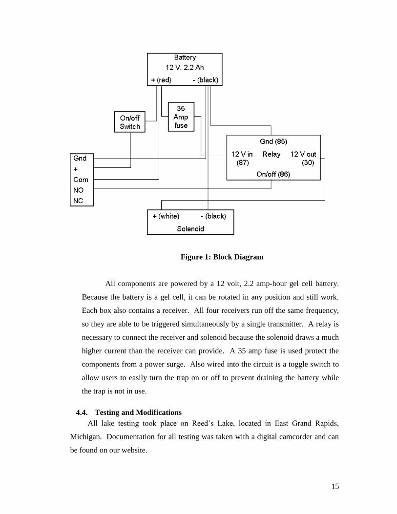
15
Figure 1: Block Diagram
All components are powered by a 12 volt, 2.2 amp-hour gel cell battery.
Because the battery is a gel cell, it can be rotated in any position and still work.
Each box also contains a receiver. All four receivers run off the same frequency,
so they are able to be triggered simultaneously by a single transmitter. A relay is
necessary to connect the receiver and solenoid because the solenoid draws a much
higher current than the receiver can provide. A 35 amp fuse is used protect the
components from a power surge. Also wired into the circuit is a toggle switch to
allow users to easily turn the trap on or off to prevent draining the battery while
the trap is not in use.
4.4. Testing and Modifications
All lake testing took place on Reed’s Lake, located in East Grand Rapids,
Michigan. Documentation for all testing was taken with a digital camcorder and can
be found on our website.
16
4.4.1. Basic Design and Spring Force Test
Our initial testing took place on March 31, 2006. First, we tested the force
to pull the wet net through the water to a vertical height of four feet above the
water surface. This was done using our initial prototype and a scale. The force to
pull up approximately 15 feet of net was measured to be 20 pounds. Also, the
initial spring and ratchet system was set up, tested, and analyzed. This testing
verified that releasing the locking pin would pull the nets out of the water.
4.4.2. Spring Test
We used our initial prototype to decide which spring to use in the final
prototype. A 90 pound garage door spring, an extra-stretch extension spring, and
clock spring were tested. One end of the springs was fixed and the other ends of
the springs were stretched. They were weighted down with 15 pound weights and
stretched to their maximum ability. The distance the springs pulled the weights
up was measured. We chose to use 90 pound garage door springs for our final
prototype because they were able to get the force and distance required and were
also widely available.
4.4.3. Working Prototype Test
The second testing in the lake took place on April 28, 2006. The setup
process for the prototype was timed and analyzed for ease and simplicity. A
problem discovered during this testing was that the cable attached to the nets had
a tendency to drift to the center of the trap. This was due to the tension on the
cables between each pole after they were attached. After triggering the trap, it
was clear that that drifting nets caused the cables to jam the ratchet mechanisms
and stop the nets from rising out of the water. To solve this problem, we used
0.75 inch diameter conduit make a cable guides. So, instead of the cables being
attached directly to the nets, they would be attached to rings that would slide up
and down the guides.
4.4.4. Modified Prototype Test
The final testing event took place on May 3, 2006. The setup was again
timed during this test. We found that it took approximately 15 minutes for two
17
people to set up the trap. The new cable guides were used during this test. They
kept the nets tight to the poles, but increased the force necessary to pull the nets
out of the water because of the friction between the rings and the conduit.
We found that in order to achieve the best performance of the rising nets,
initial pre-tension of the spring was needed. To do this, we fashioned a device
with a long hook at the end that is inserted into the end of the pole. The hooked
end is used to pull the springs down and bolts and used to keep the springs in
place.
5. Project Management
5.1. Team Organization
Because our team consisted of only three people, tasks tended to overlap and
specific roles were not assigned to each member. The workload was shared fairly
equally among teammates. At times, however, it was necessary for one person to
take responsibility over a specific part of the project to ensure that the work would be
completed correctly in that area while the others assisted. Ashley was responsible for
managing the budget, updating the website, and coordinating the purchase of
materials. Chad was the AutoCAD Inventor specialist. He drew out each component
in AutoCAD and also made an assembly drawing. Ann kept the group in line with
the class schedule of deliverables. Also, because we lost our electrical team member
after the first semester, Ann and Chad took over the electrical components. Overall,
our working styles complimented each other and helped to complete the project
successfully.
5.2. Work Breakdown Structure
Our work schedule in the fall consisted of meeting one to two set times a week,
depending on the amount of work or documents that needed to be completed. During
January, weekly meetings were called in order to keep the team focused. In the
spring, the number of meetings increased to as many as necessary in order to
complete the project in time. Our team was devoted to finishing project and put in
the time necessary to make it a success.

18
Meeting time was used for brainstorming, design, review, task assignment,
planning, and managing the budget. Meeting documentation was taken by each team
member and stored in their Senior Design project workbook. All documents were
saved in the team two folder on the X:/ drive, which is specific to Senior Design.
Budget updates were put in the administrative folder on the X:/ drive. Information on
the project and team can be found on the project website, at
http://engr.calvin.edu/SeniorDesign/SeniorDesign05-06/team02/.
5.3. Schedule
A preliminary schedule was drawn up using Microsoft Project. This schedule
was followed very closely during the fall semester. However, in January, after
finding most of the electrical components specified were unavailable, we were forced
to analyze different design alternatives for our project. This put our team behind our
preliminary schedule. In the spring semester, we found the best way to keep on
schedule was to follow the course syllabus and keep a working task schedule in our
planners and on our dry erase board. Our team found that communication was vital to
staying on schedule and meeting deadlines.
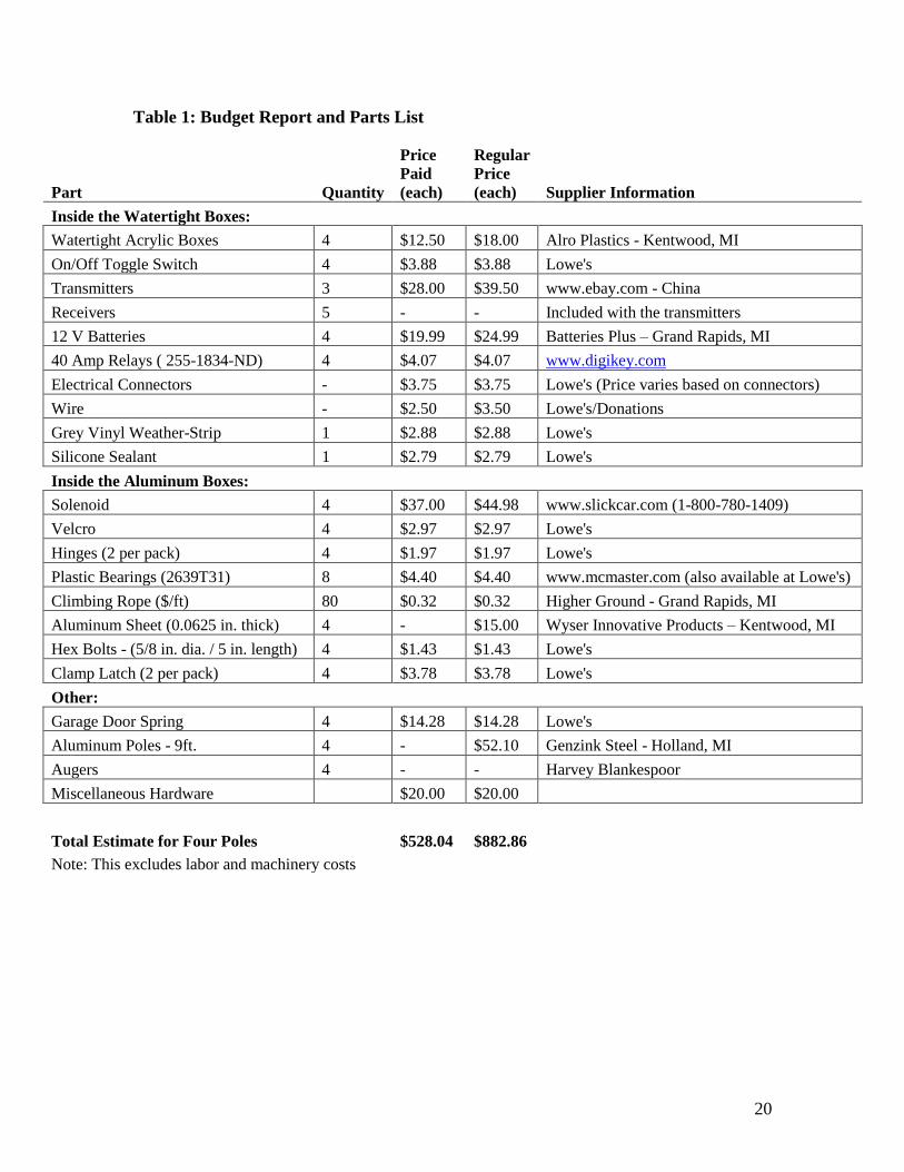
5.4. Budget
The budget for our project consisted of $300.00 given by the Calvin College
Engineering Department. Also, many donations and discounts were given to our
team by people in industry. Materials were thoroughly researched to ensure we were
obtaining the least expensive component, without compromising quality.
Unfortunately, we nearly doubled our budget and spent $528.04. After discussing
this issue with our team mentor, Professor Ned Nielsen, we were approved to
continue with our project, despite that we were over our budget. The reason we were
able to continue our project is because some civil Senior Design teams would not use
their project budget money. So their extra money would be able to cover the rest of
our project expenses.
The complete budget report can be seen below in Table 1. Included is the price
paid by our team, as well as the regular pricing without the discounts we received.

19
Additional purchases needed to include a new set of receivers and transmitters and a
new nylon net. These expenses will be covered by SICon.
20
Table 1: Budget Report and Parts List
Part Quantity
Price
Paid
(each)
Regular
Price
(each) Supplier Information
Inside the Watertight Boxes:
Watertight Acrylic Boxes 4 $12.50 $18.00 Alro Plastics - Kentwood, MI
On/Off Toggle Switch 4 $3.88 $3.88 Lowe's
Transmitters 3 $28.00 $39.50 www.ebay.com - China
Receivers 5 - - Included with the transmitters
12 V Batteries 4 $19.99 $24.99 Batteries Plus – Grand Rapids, MI
40 Amp Relays ( 255-1834-ND) 4 $4.07 $4.07 www.digikey.com
Electrical Connectors - $3.75 $3.75 Lowe's (Price varies based on connectors)
Wire - $2.50 $3.50 Lowe's/Donations
Grey Vinyl Weather-Strip 1 $2.88 $2.88 Lowe's
Silicone Sealant 1 $2.79 $2.79 Lowe's
Inside the Aluminum Boxes:
Solenoid 4 $37.00 $44.98 www.slickcar.com (1-800-780-1409)
Velcro 4 $2.97 $2.97 Lowe's
Hinges (2 per pack) 4 $1.97 $1.97 Lowe's
Plastic Bearings (2639T31) 8 $4.40 $4.40 www.mcmaster.com (also available at Lowe's)
Climbing Rope ($/ft) 80 $0.32 $0.32 Higher Ground - Grand Rapids, MI
Aluminum Sheet (0.0625 in. thick) 4 - $15.00 Wyser Innovative Products – Kentwood, MI
Hex Bolts - (5/8 in. dia. / 5 in. length) 4 $1.43 $1.43 Lowe's
Clamp Latch (2 per pack) 4 $3.78 $3.78 Lowe's
Other:
Garage Door Spring 4 $14.28 $14.28 Lowe's
Aluminum Poles - 9ft. 4 - $52.10 Genzink Steel - Holland, MI
Augers 4 - - Harvey Blankespoor
Miscellaneous Hardware $20.00 $20.00
Total Estimate for Four Poles $528.04 $882.86
Note: This excludes labor and machinery costs
21
6. Conclusion
6.1. Lessons Learned
This project provided us with an experience similar to what we should expect in
industry and we learned many lessons from this experience. First, we were forced to
make and follow our own schedule. We were given deliverable deadlines, but our
overall schedule was our responsibility. Second, we soon discovered that everything
took a lot longer than we expected. All of the time we planned for tasks should have
at least been tripled. In the end, we were working furiously to complete our
prototype. Third, we learned that nothing runs as smoothly in reality as it does on
paper. There were many different components that needed to be adjusted during
production that we had not planned for. Also, testing should be done often to ensure
problems are caught early on rather than after components are purchased or
assembled. Fourth, communication is vital to the success of a project. Often we
found that we thought we were all thinking the same thing, we soon found out we all
had different ideas and viewpoints. Therefore, effective communication skills were
very important in our success. Finally, losing a team member put us in a situation
that is often encountered in industry. This situation forced us to take responsibility of
our project and areas that were not necessarily assigned to us or were our area of
strength. These are just a few of the lessons we will take with us as we begin our
careers.
6.2. What We Would Have Done Differently
If we were to do this project again there are a few things that we would change.
First, we would make the pulley systems narrower overall so that there would be
room for washers to fit between the pulleys and the inside walls. We had difficulties
making the pulleys fit inside the housings without them scrapping their inside walls.
This produced a lot of friction, which greatly reduced the ease at which the pulleys
rotated. It also created points where the pulleys would stick and prevent the nets from
rising as high as they could. Washers would increase the ease at which the pulleys
rotate and prevent wear on the side walls and pulleys.
Another advantage to using washers is that the lever arms would have worked
better. Because the gears were so close to the walls, the lever arms had to be rounded
22
down to allow them to rotate past the walls without hitting them. Spacing the pulleys
away from the walls, would allow for more clearance of the lever arms, making them
run smoother.
We would use thicker plastic bushings. After we installed our bushings, we
realized that there was not enough clearance between the inside of the pulleys and the
bolts for the knots that hold the cables in place to be tied. Since we had already
drilled the holes for our bolts in our housings, we decided to keep the bushings and
adjust our bolts to fit the design. We had to fabricate our own bolts by turning down
their centers and milling the end of the bolts flat. If we used thicker bushings, we
could have used smaller bolts with more clearance and avoided a lot of extra work
and time spent.
The final thing that we would change would be to use a thicker aluminum sheets
for the door panels. After we did our testing, we realized that there was a higher
force pushing on our lever arms than we anticipated. Under higher loads, the
aluminum sheets do deform slightly and over time it might deform permanently. A
thicker sheet would allow for even higher spring forces to be used in the future.
6.3. Future Work
Future work for this project includes providing training to SICon for the
trapping device. We will be assisting them during their first Common Merganser
duck trapping on June 1, 2006 at Glen Lake.
7. Acknowledgements
We would like to acknowledge the people listed below for their time, guidance,
donations, and/or any other help they have given to our team. Without them, we would
not have been successful.
Alro Plastics
Greg Bock
Bob DeKraker
Genzink Steel – For the donation of the aluminum poles
Ned Nielsen – Our team advisor
Dave Ryskamp

23
SICon L.L.C
Chuck Spoelhof
Ren Tubergen – Our team mentor
Wyser Innovative Products – For the donation of the laser-cut gears and aluminum for the
housings

24
Appendices

25
Appendix A: User’s Manual

26
User’s Manual
For the Merganser Duck Trap
** Warning** This device contains moving parts that could cause serious injury or death
if not operated properly. Please read the following manual before operating this device.

27
Step 1. Arrange the components: Lay out the components to each pole to make sure that you have
everything that you’ll need.
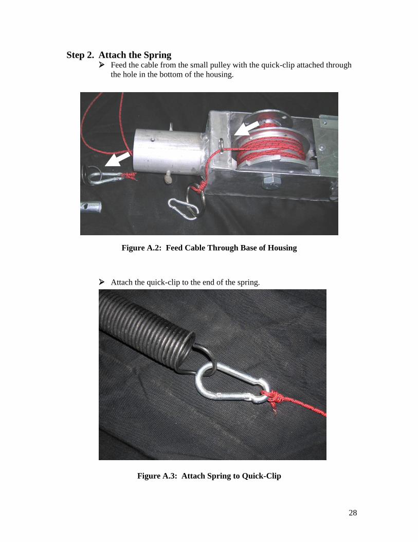
Figure A.1: Trap Components
28
Step 2. Attach the Spring Feed the cable from the small pulley with the quick-clip attached through
the hole in the bottom of the housing.
Attach the quick-clip to the end of the spring.
Figure A.2: Feed Cable Through Base of Housing
Figure A.3: Attach Spring to Quick-Clip
29
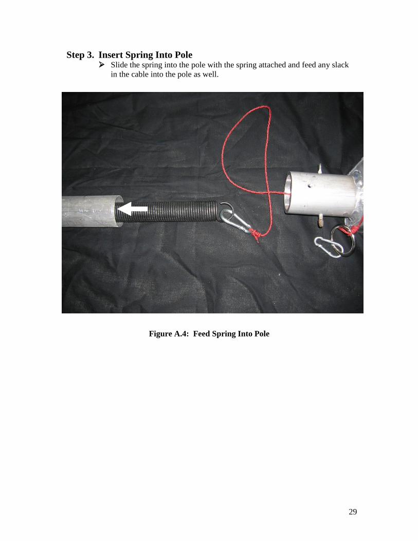
Step 3. Insert Spring Into Pole Slide the spring into the pole with the spring attached and feed any slack
in the cable into the pole as well.
Figure A.4: Feed Spring Into Pole
30
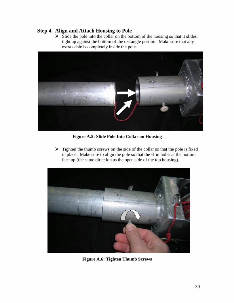
Step 4. Align and Attach Housing to Pole Slide the pole into the collar on the bottom of the housing so that it slides
tight up against the bottom of the rectangle portion. Make sure that any
extra cable is completely inside the pole.
Tighten the thumb screws on the side of the collar so that the pole is fixed
in place. Make sure to align the pole so that the ¼ in holes at the bottom
face up (the same direction as the open side of the top housing).
Figure A.5: Slide Pole Into Collar on Housing
Figure A.6: Tighten Thumb Screws

31
Step 5. Fix Spring In Place Stand the pole on end so that the spring slides down the pole and then set
the pole back on the ground. Then feed the long hook up the pole from
the bottom and hook onto the end of the spring.
Extend the spring downward until it is inline with the fourth hole.
With the help of another person, feed a bolt through the hole and through
the loop on the end of the spring and thread a nut on the end fixing it in
place. Then remove the long hook from the spring and take it out from the
pole.
Figure A.7: Feed the Long Hook in the Pole
Figure A.8: Extend the Spring by Pulling Down on the long Hook
Figure A.9: Feed the Bolt Through the End of the Spring
32
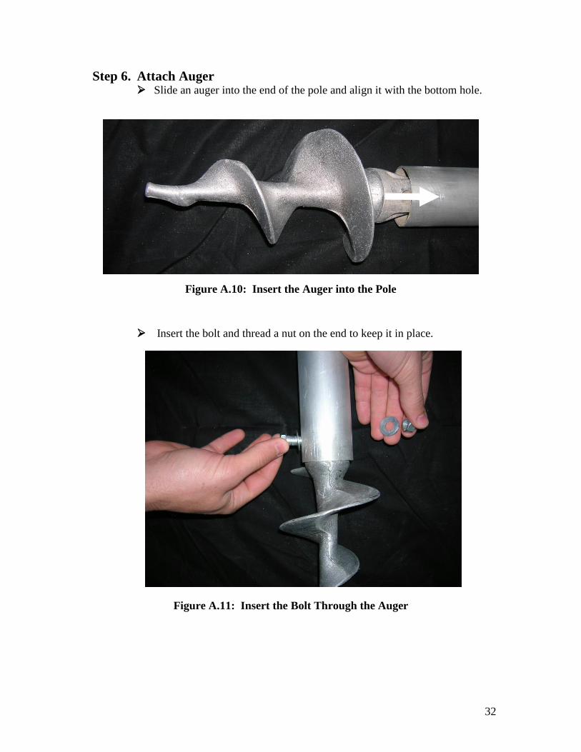
Step 6. Attach Auger Slide an auger into the end of the pole and align it with the bottom hole.
Insert the bolt and thread a nut on the end to keep it in place.
Figure A.10: Insert the Auger into the Pole
Figure A.11: Insert the Bolt Through the Auger
33
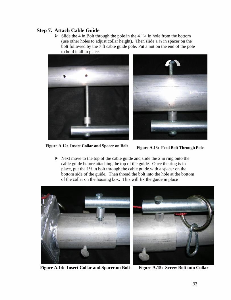
Step 7. Attach Cable Guide Slide the 4 in Bolt through the pole in the 4
th ¼ in hole from the bottom
(use other holes to adjust collar height). Then slide a ½ in spacer on the
bolt followed by the 7 ft cable guide pole. Put a nut on the end of the pole
to hold it all in place.
Next move to the top of the cable guide and slide the 2 in ring onto the
cable guide before attaching the top of the guide. Once the ring is in
place, put the 1½ in bolt through the cable guide with a spacer on the
bottom side of the guide. Then thread the bolt into the hole at the bottom
of the collar on the housing box. This will fix the guide in place
Figure A.12: Insert Collar and Spacer on Bolt Figure A.13: Feed Bolt Through Pole
Figure A.14: Insert Collar and Spacer on Bolt Figure A.15: Screw Bolt into Collar
34
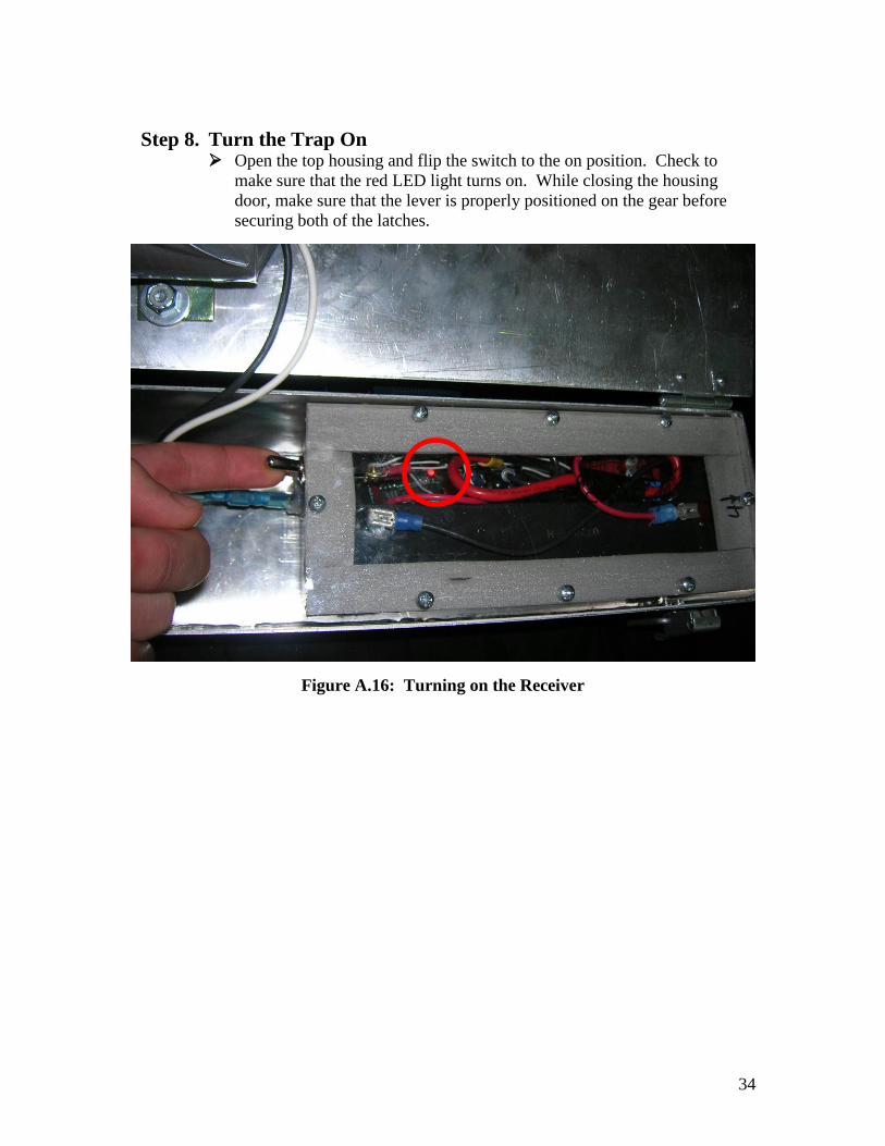
Step 8. Turn the Trap On Open the top housing and flip the switch to the on position. Check to
make sure that the red LED light turns on. While closing the housing
door, make sure that the lever is properly positioned on the gear before
securing both of the latches.
Figure A.16: Turning on the Receiver

35
Step 9. Set the Poles Warning: The poles are top heavy when they are full assembled. Hold
the assembled pole closer to the top so that it doesn’t cause you to fall as
you are carrying it.
Begin by screwing one of the poles into the ground in the desired location
of the lake. Turn the poles by hand until it becomes too difficult. Then
continue screwing them into the ground by inserting the steel rod into the
available holes along the pole and turning in the pole deeper (this may
require two people if the lake bottom is difficult to screw into).
Repeat this process with the other three poles in each corner of the trap.
Figure A.17: Turning in the Poles
Figure A.18: All Four Poles Set
36
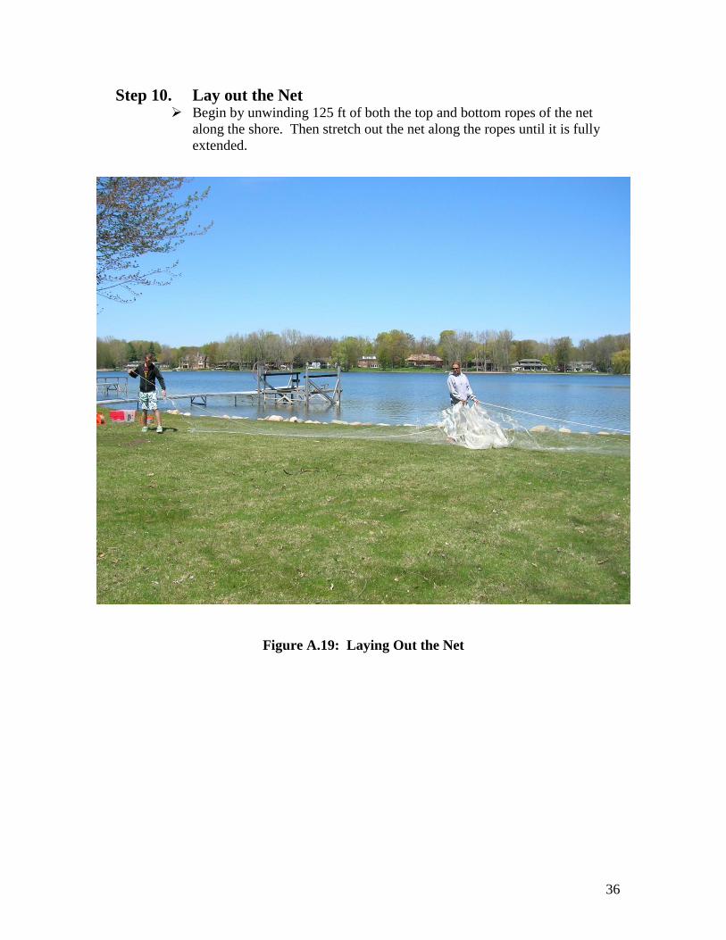
Step 10. Lay out the Net Begin by unwinding 125 ft of both the top and bottom ropes of the net
along the shore. Then stretch out the net along the ropes until it is fully
extended.
Figure A.19: Laying Out the Net

37
Step 11. Attach the Net Begin by attaching the net on the pole that is closest to shore. Pull down
the 2 in ring on the end of the red cable until it is approximately 3 ft above
the water. Then attach the end of the net to the quick-clip and clip it onto
the 2 in ring. When clipping on the net make sure that at least one loop of
the net is looped through the clip with the top cable to ensure that the net
will not pull away from the pole when it is being drawn upwards.
Once the top of the net is attached to the pole, loop the lead line on the
bottom of the net around the pole near the sand to ensure that it stays in
place when while the net is set up.
Figure A.20: Attaching the Net
Figure A.21: Attaching the Lead Line
38
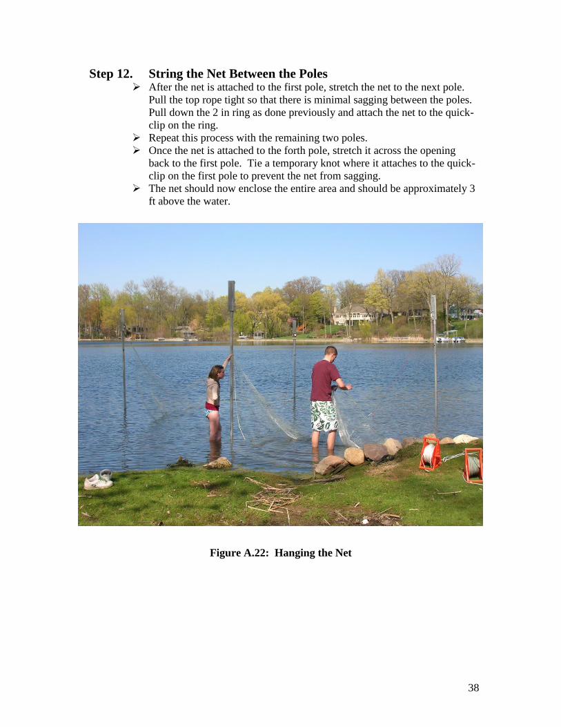
Step 12. String the Net Between the Poles After the net is attached to the first pole, stretch the net to the next pole.
Pull the top rope tight so that there is minimal sagging between the poles.
Pull down the 2 in ring as done previously and attach the net to the quick-
clip on the ring.
Repeat this process with the remaining two poles.
Once the net is attached to the forth pole, stretch it across the opening
back to the first pole. Tie a temporary knot where it attaches to the quick-
clip on the first pole to prevent the net from sagging.
The net should now enclose the entire area and should be approximately 3
ft above the water.
Figure A.22: Hanging the Net

39
Step 13. Submerge the Net Begin at the first pole and finish pulling the net down until it is
approximately 1 ft under water. Repeat this step on the remaining three
poles so that the entire net is submerged underwater.
Figure A.23: Submerging the Net

40
Step 14. Trigger the Trap Once the net is in place and the ducks are
within the netted area, the trap can be
triggered. To trigger the trap PRESS and
HOLD down the button until the net has
been completely lifted out of the water. It
is very important that you hold the button
down the entire time the net is moving.
Failure to do so could result in damaging
parts of the triggering mechanism as well
as stopping the net before it reaches the
max height. This creates the potential for
the ducks to escape from the trap.
Figure A.24: Pressing the Button
Figure A.25: Net Springing Upward

41
Please use responsibly.
42
Appendix B: Design Alternatives
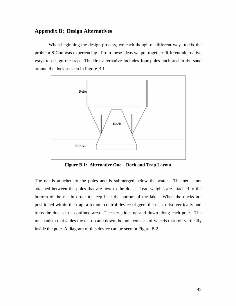
When beginning the design process, we each though of different ways to fix the
problem SICon was experiencing. From these ideas we put together different alternative
ways to design the trap. The first alternative includes four poles anchored in the sand
around the dock as seen in Figure B.1.
Figure B.1: Alternative One – Dock and Trap Layout
The net is attached to the poles and is submerged below the water. The net is not
attached between the poles that are next to the dock. Lead weights are attached to the
bottom of the net in order to keep it at the bottom of the lake. When the ducks are
positioned within the trap, a remote control device triggers the net to rise vertically and
traps the ducks in a confined area. The net slides up and down along each pole. The
mechanism that slides the net up and down the pole consists of wheels that roll vertically
inside the pole. A diagram of this device can be seen in Figure B.2.

43
Figure B.2: Alternative One – Wheel Device Top View
Design alternative two is similar to alternative one, with four poles placed around
the dock. However, the poles are in a wider area, as seen in Figure B.3.
Figure B.3: Alternative Two – Dock and Trap Layout
The basic function of alternative two is the same as alternative one, except that it is more
flexible than alternative one. Instead of being position around the dock, alternative two
can be used in multiple locations. The net will be present on all four sides, instead of just
44
three sides. This flexibility in location is beneficial for SICon because the ducks learn the
locations of the traps.
Alternative three consists of a box resting at the bottom of the lake. It contains
four retractable arms or linkages that are attached to a net. The net is outside of the box
initially, submerged below the water. When the trap is triggered, the arms shoot out of
the box at an angle via the corners. When the arms are in the final position, the confined
area will be created with the nets.
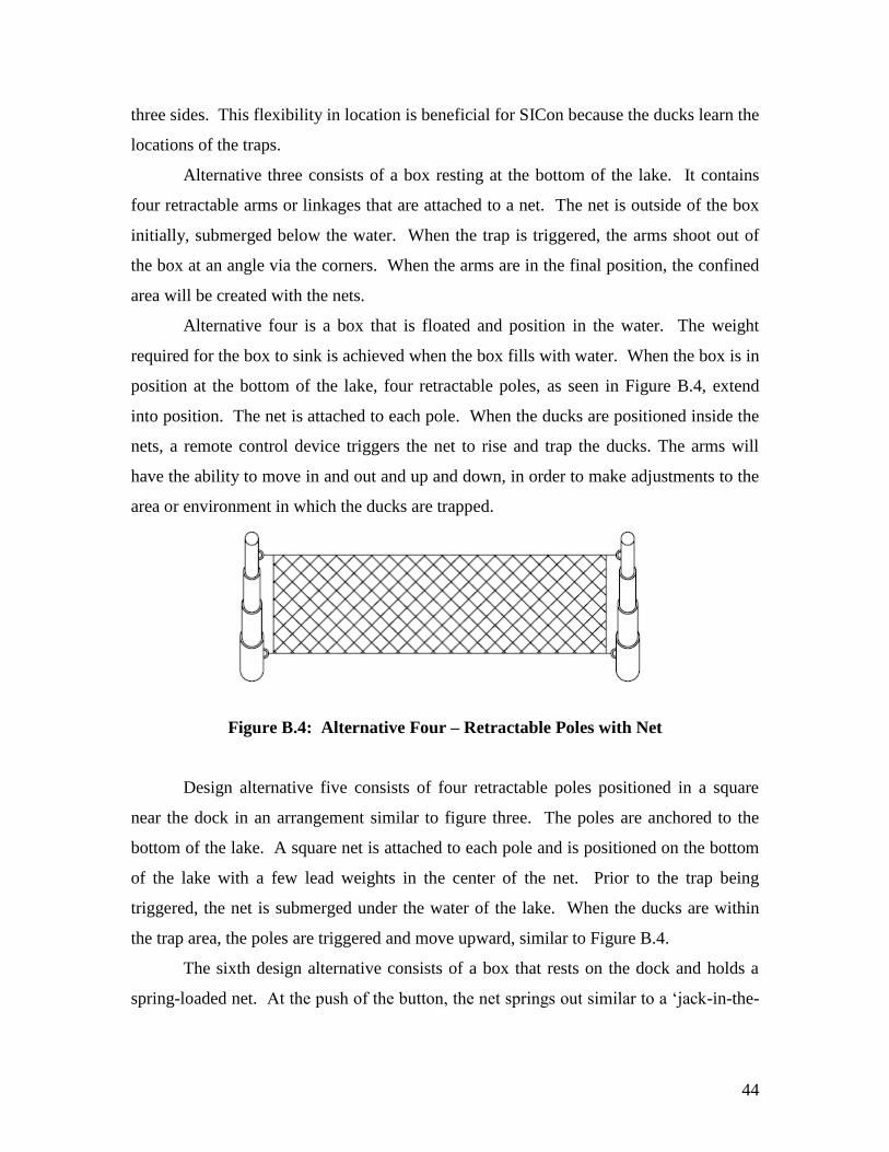
Alternative four is a box that is floated and position in the water. The weight
required for the box to sink is achieved when the box fills with water. When the box is in
position at the bottom of the lake, four retractable poles, as seen in Figure B.4, extend
into position. The net is attached to each pole. When the ducks are positioned inside the
nets, a remote control device triggers the net to rise and trap the ducks. The arms will
have the ability to move in and out and up and down, in order to make adjustments to the
area or environment in which the ducks are trapped.
Figure B.4: Alternative Four – Retractable Poles with Net
Design alternative five consists of four retractable poles positioned in a square
near the dock in an arrangement similar to figure three. The poles are anchored to the
bottom of the lake. A square net is attached to each pole and is positioned on the bottom
of the lake with a few lead weights in the center of the net. Prior to the trap being
triggered, the net is submerged under the water of the lake. When the ducks are within
the trap area, the poles are triggered and move upward, similar to Figure B.4.
The sixth design alternative consists of a box that rests on the dock and holds a
spring-loaded net. At the push of the button, the net springs out similar to a ‘jack-in-the-

45
box’, encompassing the dock. The net will sink to the bottom in order to prevent the
ducks from escaping.
After deciding to begin our design with design alternative two, different
alternatives for what type of mechanism or device would actually raise the nets up out of
the water. One alternative to aid in triggering the trap that was analyzed is using
compressed air cylinders. When the trap is triggered, the air cylinders release enough
pressure to push the poles up. However, when reviewing this alternative more closely,
we felt it would introduce possibilities for failure. For example, if water leaked into the
air pump apparatus, the operators would have to let the air pump apparatus dry
completely before being able to reuse the trap.
Another alternative to aid in triggering the tap includes wireless solenoids. When
used in conjunction with a mechanical device, they would produce enough force to aid in
pulling the nets out of the water.
Our preliminary design is a combination of many of the design alternatives. As
shown in Figure B.5, it consists of four poles secured into the bottom of the lake with
augers.
Figure B.5: Initial Setup of Preliminary Design
Each pole has its own mechanical device consisting of two pulleys and a spring to
raise the net vertically out of the water. The bottom of the net is attached to a lead-lined
46
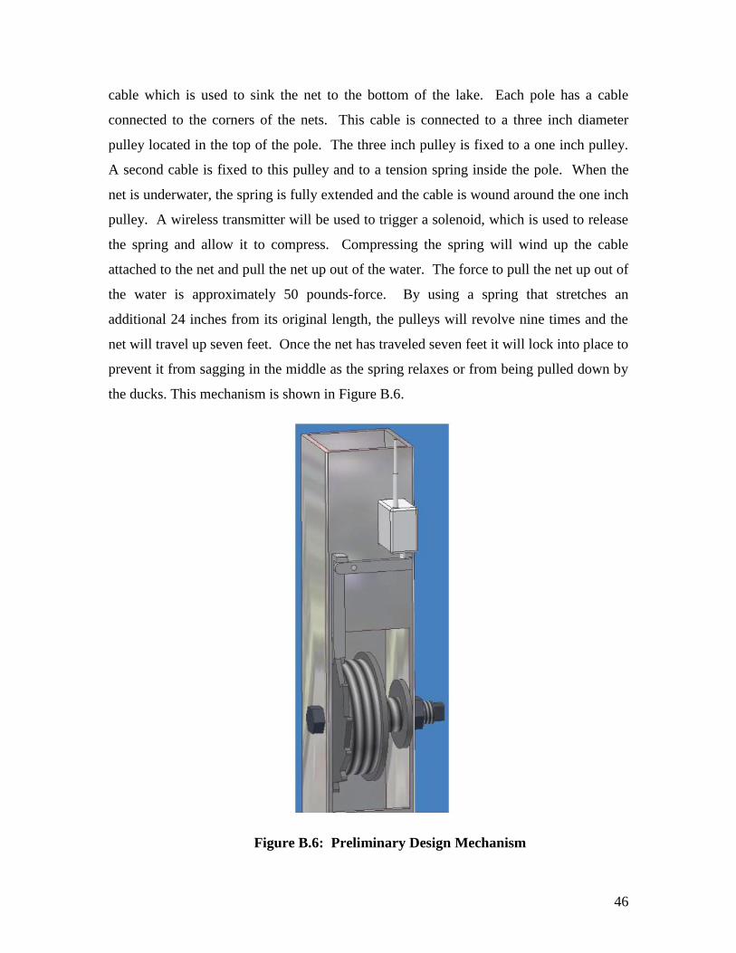
cable which is used to sink the net to the bottom of the lake. Each pole has a cable
connected to the corners of the nets. This cable is connected to a three inch diameter
pulley located in the top of the pole. The three inch pulley is fixed to a one inch pulley.
A second cable is fixed to this pulley and to a tension spring inside the pole. When the
net is underwater, the spring is fully extended and the cable is wound around the one inch
pulley. A wireless transmitter will be used to trigger a solenoid, which is used to release
the spring and allow it to compress. Compressing the spring will wind up the cable
attached to the net and pull the net up out of the water. The force to pull the net up out of
the water is approximately 50 pounds-force. By using a spring that stretches an
additional 24 inches from its original length, the pulleys will revolve nine times and the
net will travel up seven feet. Once the net has traveled seven feet it will lock into place to
prevent it from sagging in the middle as the spring relaxes or from being pulled down by
the ducks. This mechanism is shown in Figure B.6.
Figure B.6: Preliminary Design Mechanism
47
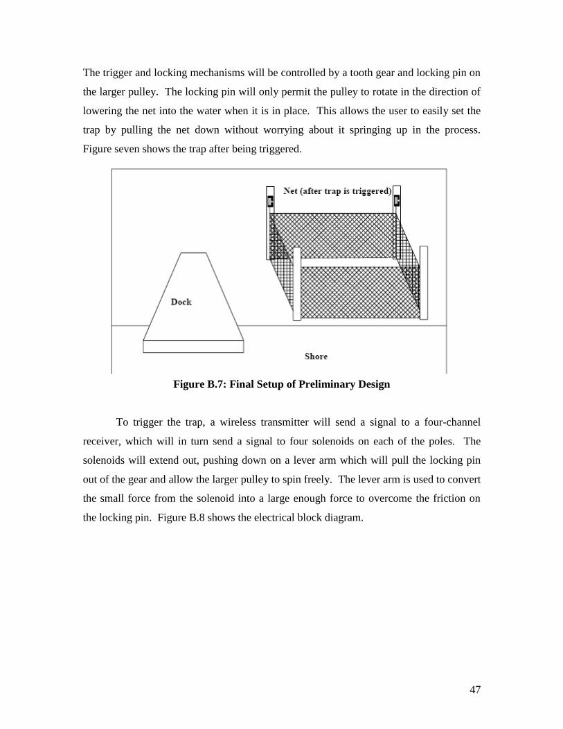
The trigger and locking mechanisms will be controlled by a tooth gear and locking pin on
the larger pulley. The locking pin will only permit the pulley to rotate in the direction of
lowering the net into the water when it is in place. This allows the user to easily set the
trap by pulling the net down without worrying about it springing up in the process.
Figure seven shows the trap after being triggered.
Figure B.7: Final Setup of Preliminary Design
To trigger the trap, a wireless transmitter will send a signal to a four-channel
receiver, which will in turn send a signal to four solenoids on each of the poles. The
solenoids will extend out, pushing down on a lever arm which will pull the locking pin
out of the gear and allow the larger pulley to spin freely. The lever arm is used to convert
the small force from the solenoid into a large enough force to overcome the friction on
the locking pin. Figure B.8 shows the electrical block diagram.
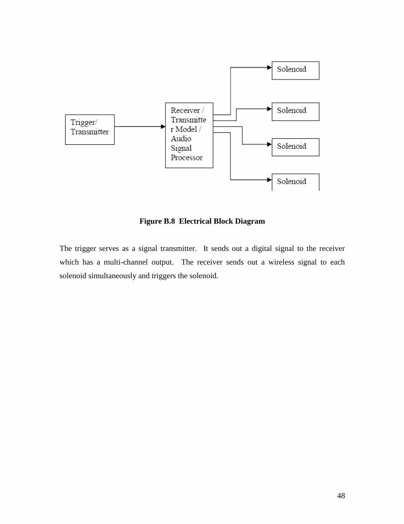
48
Figure B.8 Electrical Block Diagram
The trigger serves as a signal transmitter. It sends out a digital signal to the receiver
which has a multi-channel output. The receiver sends out a wireless signal to each
solenoid simultaneously and triggers the solenoid.
49
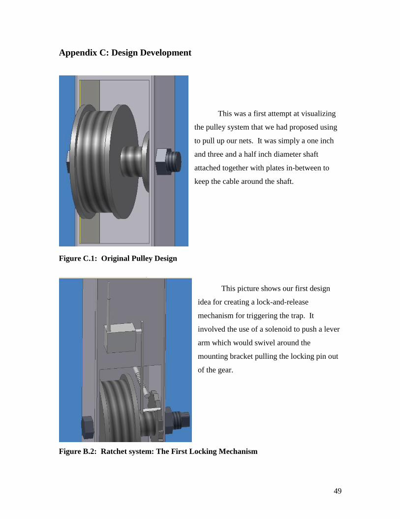
Appendix C: Design Development
This was a first attempt at visualizing
the pulley system that we had proposed using
to pull up our nets. It was simply a one inch
and three and a half inch diameter shaft
attached together with plates in-between to
keep the cable around the shaft.
Figure C.1: Original Pulley Design
This picture shows our first design
idea for creating a lock-and-release
mechanism for triggering the trap. It
involved the use of a solenoid to push a lever
arm which would swivel around the
mounting bracket pulling the locking pin out
of the gear.
Figure B.2: Ratchet system: The First Locking Mechanism

50
This was a new design we
came up with that was much
stronger and more robust. It also
used a long lever arm attached to
the solenoid. This was because at
the time we were unable to find a
solenoid with a strong enough
stroke force to remove our locking
pin from the gear. We used a lever
arm to convert the small, downward
force of the solenoid to a large,
upward force on the locking pin.
With this design, the locking pin
was pinned into two slotted holes
which allowed vertical movement
over the gear teeth. A closer image
of the design is shown below.
Figure C.3: Two-Part Lever Arm Locking Pin Design
51
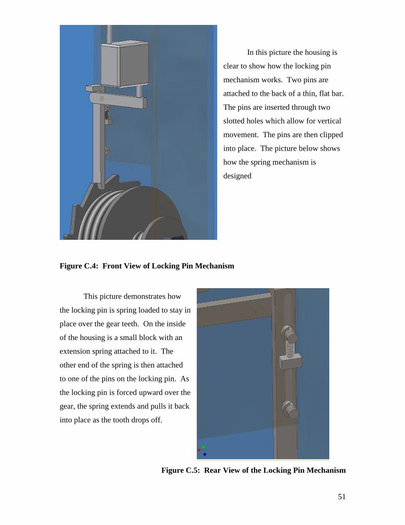
In this picture the housing is
clear to show how the locking pin
mechanism works. Two pins are
attached to the back of a thin, flat bar.
The pins are inserted through two
slotted holes which allow for vertical
movement. The pins are then clipped
into place. The picture below shows
how the spring mechanism is
designed
Figure C.4: Front View of Locking Pin Mechanism
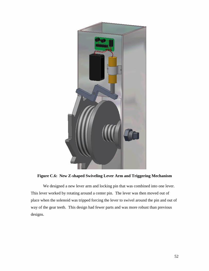
This picture demonstrates how
the locking pin is spring loaded to stay in
place over the gear teeth. On the inside
of the housing is a small block with an
extension spring attached to it. The
other end of the spring is then attached
to one of the pins on the locking pin. As
the locking pin is forced upward over the
gear, the spring extends and pulls it back
into place as the tooth drops off.
Figure C.5: Rear View of the Locking Pin Mechanism
52
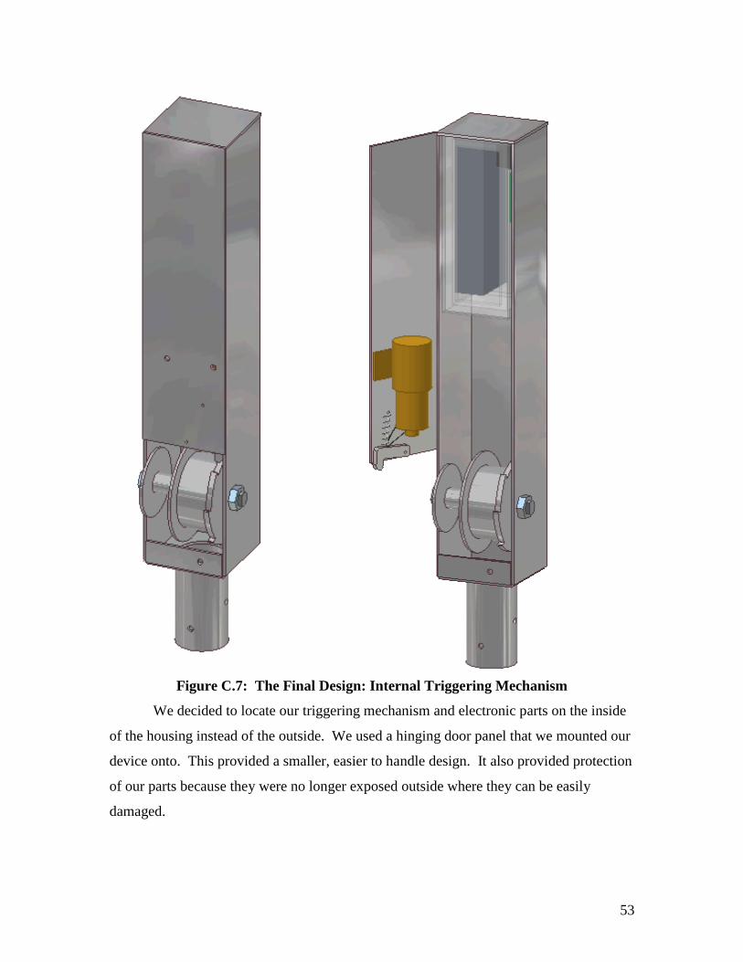
Figure C.6: New Z-shaped Swiveling Lever Arm and Triggering Mechanism
We designed a new lever arm and locking pin that was combined into one lever.
This lever worked by rotating around a center pin. The lever was then moved out of
place when the solenoid was tripped forcing the lever to swivel around the pin and out of
way of the gear teeth. This design had fewer parts and was more robust than previous
designs.
53
Figure C.7: The Final Design: Internal Triggering Mechanism
We decided to locate our triggering mechanism and electronic parts on the inside
of the housing instead of the outside. We used a hinging door panel that we mounted our
device onto. This provided a smaller, easier to handle design. It also provided protection
of our parts because they were no longer exposed outside where they can be easily
damaged.
54
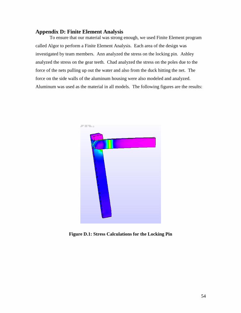
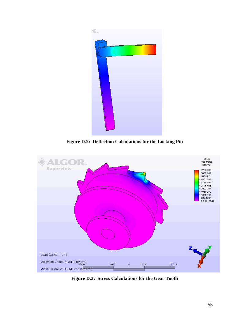
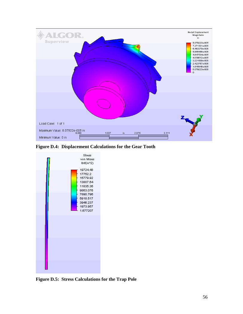
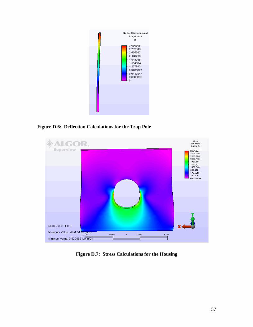
Appendix D: Finite Element Analysis To ensure that our material was strong enough, we used Finite Element program
called Algor to perform a Finite Element Analysis. Each area of the design was
investigated by team members. Ann analyzed the stress on the locking pin. Ashley
analyzed the stress on the gear teeth. Chad analyzed the stress on the poles due to the
force of the nets pulling up out the water and also from the duck hitting the net. The
force on the side walls of the aluminum housing were also modeled and analyzed.
Aluminum was used as the material in all models. The following figures are the results:
Figure D.1: Stress Calculations for the Locking Pin
55
Figure D.2: Deflection Calculations for the Locking Pin
Figure D.3: Stress Calculations for the Gear Tooth
56
Figure D.4: Displacement Calculations for the Gear Tooth
Figure D.5: Stress Calculations for the Trap Pole
57
Figure D.6: Deflection Calculations for the Trap Pole
Figure D.7: Stress Calculations for the Housing

58
Figure D.8: Deflection Calculation for the Housing