MenAMI Trides 02 - Multiplex Eng. Ltd. · SWAN and its representatives maintain a fully trained...
96
AMI Trides Version 5.31 and higher A-96.250.111 / 281113 Operator’s Manual
-
Upload
nguyenkhue -
Category
Documents
-
view
217 -
download
0
Transcript of MenAMI Trides 02 - Multiplex Eng. Ltd. · SWAN and its representatives maintain a fully trained...
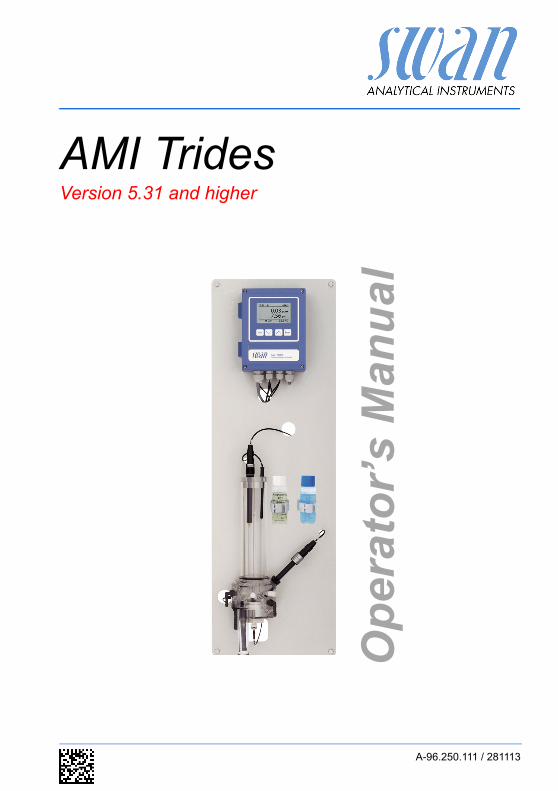
AMI TridesVersion 5.31 and higher
A-96.250.111 / 281113
Op
erat
or’
s M
anu
al
© 2012, SWAN ANALYTISCHE INSTRUMENTE AG, Switzerland, all rights reserved
subject to change without notice
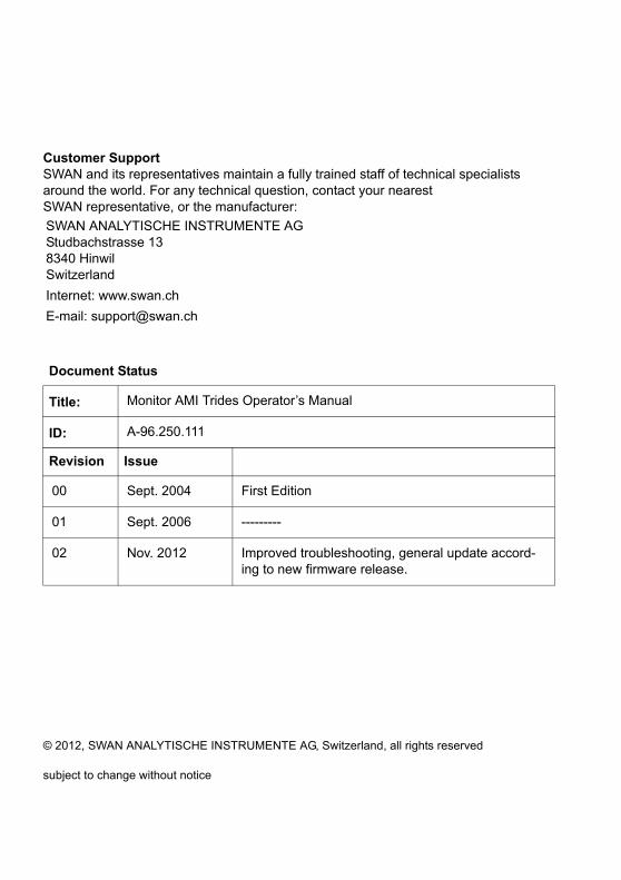
Customer SupportSWAN and its representatives maintain a fully trained staff of technical specialists around the world. For any technical question, contact your nearest SWAN representative, or the manufacturer:
SWAN ANALYTISCHE INSTRUMENTE AGStudbachstrasse 138340 HinwilSwitzerland
Internet: www.swan.ch
E-mail: [email protected]
Document Status
Title: Monitor AMI Trides Operator’s Manual
ID: A-96.250.111
Revision Issue
00 Sept. 2004 First Edition
01 Sept. 2006 ---------
02 Nov. 2012 Improved troubleshooting, general update accord-ing to new firmware release.

AMI Trides
Table of Contents
1. Safety Instructions . . . . . . . . . . . . . . . . . . . . . . . . . . . . . . . . . . . 41.1. Warning Notices . . . . . . . . . . . . . . . . . . . . . . . . . . . . . . . . . . . . . . 51.2. General Safety Regulations . . . . . . . . . . . . . . . . . . . . . . . . . . . . . 71.3. Restriction for use. . . . . . . . . . . . . . . . . . . . . . . . . . . . . . . . . . . . . 8
2. Product Description . . . . . . . . . . . . . . . . . . . . . . . . . . . . . . . . . . 92.1. Description of the System. . . . . . . . . . . . . . . . . . . . . . . . . . . . . . . 92.2. Instrument Specification . . . . . . . . . . . . . . . . . . . . . . . . . . . . . . . . 142.3. Instrument Overview. . . . . . . . . . . . . . . . . . . . . . . . . . . . . . . . . . . 16
3. Installation. . . . . . . . . . . . . . . . . . . . . . . . . . . . . . . . . . . . . . . . . . 173.1. Installation Checklist Monitors . . . . . . . . . . . . . . . . . . . . . . . . . . . 173.2. Mounting of Instrument Panel. . . . . . . . . . . . . . . . . . . . . . . . . . . . 183.3. Connecting Sample and Waste . . . . . . . . . . . . . . . . . . . . . . . . . . 183.4. Install the Reference Electrode . . . . . . . . . . . . . . . . . . . . . . . . . . 193.5. Install the Temperature Sensor . . . . . . . . . . . . . . . . . . . . . . . . . . 203.6. Install the Optional pH or Redox Electrode . . . . . . . . . . . . . . . . . 213.6.1 Install the pH or Redox Electrode into the Flow Cell . . . . . . . . . . 213.6.2 Connect the pH Electrode to the Transmitter . . . . . . . . . . . . . . . . 223.6.3 Firmware Settings for pH/Redox Electrode . . . . . . . . . . . . . . . . . 233.7. Electrical Connections . . . . . . . . . . . . . . . . . . . . . . . . . . . . . . . . . 243.8. Connection Diagram. . . . . . . . . . . . . . . . . . . . . . . . . . . . . . . . . . . 263.9. Power Supply . . . . . . . . . . . . . . . . . . . . . . . . . . . . . . . . . . . . . . . . 273.10. Input . . . . . . . . . . . . . . . . . . . . . . . . . . . . . . . . . . . . . . . . . . . . . . . 283.11. Relay Contacts . . . . . . . . . . . . . . . . . . . . . . . . . . . . . . . . . . . . . . . 283.11.1 Alarm Relay . . . . . . . . . . . . . . . . . . . . . . . . . . . . . . . . . . . . . . . . . 283.11.2 Relay 1 and 2 . . . . . . . . . . . . . . . . . . . . . . . . . . . . . . . . . . . . . . . . 293.12. Signal Outputs . . . . . . . . . . . . . . . . . . . . . . . . . . . . . . . . . . . . . . . 313.12.1 Signal Output 1 and 2 (current outputs) . . . . . . . . . . . . . . . . . . . . 313.12.2 Signal Output 3 (optional) . . . . . . . . . . . . . . . . . . . . . . . . . . . . . . . 313.13. Interface . . . . . . . . . . . . . . . . . . . . . . . . . . . . . . . . . . . . . . . . . . . . 323.13.1 Interface RS232 . . . . . . . . . . . . . . . . . . . . . . . . . . . . . . . . . . . . . . 323.13.2 Interface RS485 . . . . . . . . . . . . . . . . . . . . . . . . . . . . . . . . . . . . . . 323.13.3 USB Interface . . . . . . . . . . . . . . . . . . . . . . . . . . . . . . . . . . . . . . . . 33
4. Instrument Setup . . . . . . . . . . . . . . . . . . . . . . . . . . . . . . . . . . . . 344.1. Establish sample flow . . . . . . . . . . . . . . . . . . . . . . . . . . . . . . . . . . 344.2. Programming . . . . . . . . . . . . . . . . . . . . . . . . . . . . . . . . . . . . . . . . 344.3. Calibration of pH electrode . . . . . . . . . . . . . . . . . . . . . . . . . . . . . . 344.4. Correction of Trides sensor . . . . . . . . . . . . . . . . . . . . . . . . . . . . . 35
A-96.250.111 / 281113 1
AMI Trides
5. Operation. . . . . . . . . . . . . . . . . . . . . . . . . . . . . . . . . . . . . . . . . . . 365.1. Keys . . . . . . . . . . . . . . . . . . . . . . . . . . . . . . . . . . . . . . . . . . . . . . . 365.2. Display . . . . . . . . . . . . . . . . . . . . . . . . . . . . . . . . . . . . . . . . . . . . . 375.3. Software Structure . . . . . . . . . . . . . . . . . . . . . . . . . . . . . . . . . . . . 385.4. Changing Parameters and values. . . . . . . . . . . . . . . . . . . . . . . . . 39
6. Maintenance . . . . . . . . . . . . . . . . . . . . . . . . . . . . . . . . . . . . . . . . 406.1. Maintenance Schedule . . . . . . . . . . . . . . . . . . . . . . . . . . . . . . . . . 406.2. Cleaning of Trides protective filter . . . . . . . . . . . . . . . . . . . . . . . . 426.3. Cleaning of Trides sensor . . . . . . . . . . . . . . . . . . . . . . . . . . . . . . . 436.4. Cleaning of Reference Electrode . . . . . . . . . . . . . . . . . . . . . . . . . 456.5. Cleaning of pH Electrode . . . . . . . . . . . . . . . . . . . . . . . . . . . . . . . 466.6. Cleaning of Flow Cell . . . . . . . . . . . . . . . . . . . . . . . . . . . . . . . . . . 476.7. Calibration of Trides Sensor . . . . . . . . . . . . . . . . . . . . . . . . . . . . . 496.7.1 Process pH . . . . . . . . . . . . . . . . . . . . . . . . . . . . . . . . . . . . . . . . . . 496.7.2 Standard pH . . . . . . . . . . . . . . . . . . . . . . . . . . . . . . . . . . . . . . . . . 506.7.3 Standard Redox . . . . . . . . . . . . . . . . . . . . . . . . . . . . . . . . . . . . . . 516.7.4 Zero Trides . . . . . . . . . . . . . . . . . . . . . . . . . . . . . . . . . . . . . . . . . . 516.7.5 Process Trides . . . . . . . . . . . . . . . . . . . . . . . . . . . . . . . . . . . . . . . 516.8. Replacing Fuses . . . . . . . . . . . . . . . . . . . . . . . . . . . . . . . . . . . . . . 536.9. Longer Stop of Operation . . . . . . . . . . . . . . . . . . . . . . . . . . . . . . . 54
7. Troubleshooting . . . . . . . . . . . . . . . . . . . . . . . . . . . . . . . . . . . . . 557.1. Diagnostic Values . . . . . . . . . . . . . . . . . . . . . . . . . . . . . . . . . . . . . 557.2. Troubleshooting List . . . . . . . . . . . . . . . . . . . . . . . . . . . . . . . . . . . 567.3. Error List . . . . . . . . . . . . . . . . . . . . . . . . . . . . . . . . . . . . . . . . . . . . 58
8. Program Overview . . . . . . . . . . . . . . . . . . . . . . . . . . . . . . . . . . . 618.1. Messages (Main Menu 1) . . . . . . . . . . . . . . . . . . . . . . . . . . . . . . . 618.2. Diagnostics (Main Menu 2) . . . . . . . . . . . . . . . . . . . . . . . . . . . . . . 628.3. Maintenance (Main Menu 3) . . . . . . . . . . . . . . . . . . . . . . . . . . . . . 638.4. Operation (Main Menu 4) . . . . . . . . . . . . . . . . . . . . . . . . . . . . . . . 648.5. Installation (Main Menu 5). . . . . . . . . . . . . . . . . . . . . . . . . . . . . . . 65
9. Program List and Explanations. . . . . . . . . . . . . . . . . . . . . . . . . 671 Messages. . . . . . . . . . . . . . . . . . . . . . . . . . . . . . . . . . . . . . . . . . 672 Diagnostics . . . . . . . . . . . . . . . . . . . . . . . . . . . . . . . . . . . . . . . . 673 Maintenance . . . . . . . . . . . . . . . . . . . . . . . . . . . . . . . . . . . . . . . 694 Operation . . . . . . . . . . . . . . . . . . . . . . . . . . . . . . . . . . . . . . . . . . 705 Installation . . . . . . . . . . . . . . . . . . . . . . . . . . . . . . . . . . . . . . . . . 71
10. Material Safety Data sheets . . . . . . . . . . . . . . . . . . . . . . . . . . . . 8610.1. Reagents. . . . . . . . . . . . . . . . . . . . . . . . . . . . . . . . . . . . . . . . . . . . 86
2 A-96.250.111 / 281113
AMI Trides
11. Default Values. . . . . . . . . . . . . . . . . . . . . . . . . . . . . . . . . . . . . . . 87
12. Index . . . . . . . . . . . . . . . . . . . . . . . . . . . . . . . . . . . . . . . . . . . . . . 90
13. Notes . . . . . . . . . . . . . . . . . . . . . . . . . . . . . . . . . . . . . . . . . . . . . . 92
A-96.250.111 / 281113 3
AMI TridesSafety Instructions
AMI Trides - Operator’s Manual
This document describes the main steps for instrument setup, oper-ation and maintenance.
1. Safety Instructions
General The instructions included in this section explain the potential risks associated with instrument operation and provide important safety practices designed to minimize these risks.If you carefully follow the information contained in this section, you can protect yourself from hazards and create a safer work environ-ment.More safety instructions are given throughout this manual, at the respective locations where observation is most important. Strictly follow all safety instructions in this publication.
Targetaudience
Operator: Qualified person who uses the equipment for its intended purpose.Instrument operation requires thorough knowledge of applications, instrument functions and software program as well as all applicable safety rules and regulations.
OM Location Keep the AMI Operator’s Manual in proximity of the instrument.
Qualification,Training
To be qualified for instrument installation and operation, you must: read and understand the instructions in this manual as well as
the Material Safety Data Sheets. know the relevant safety rules and regulations.
The symbols used for safety-related notices have the following sig-nificance:
4 A-96.250.111 / 281113

AMI TridesSafety Instructions
1.1. Warning Notices
The symbols used for safety-related notices have the following sig-nificance:
DANGER
Your life or physical wellbeing are in serious danger if such warnings are ignored. Follow the prevention instructions carefully.
WARNING
Severe injuries or damage to the equipment can occur if such warnings are ignored. Follow the prevention instructions carefully.
CAUTION
Damage to the equipment, minor injury, malfunctions or incor-rect process can be the consequence if such warnings are ig-nored. Follow the prevention instructions carefully.
MandatorySigns
The importance of the mandatory signs in this manual.
Safety goggles
Safety gloves
A-96.250.111 / 281113 5
AMI TridesSafety Instructions
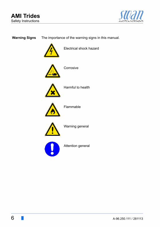
Warning Signs The importance of the warning signs in this manual.
Electrical shock hazard
Corrosive
Harmful to health
Flammable
Warning general
Attention general
6 A-96.250.111 / 281113
AMI TridesSafety Instructions
1.2. General Safety Regulations
LegalRequirements
The user is responsible for proper system operation. All precautions must be followed to ensure safe operation of the instrument.
Spare Partsand
Disposables
Use only official SWAN spare parts and disposables. If other parts are used during the normal warranty period, the manufacturer’s warranty is voided.
Modifications Modifications and instrument upgrades shall only be carried out by an authorized Service Technician. SWAN will not accept responsi-bility for any claim resulting from unauthorized modification or alter-ation.
WARNING
Electrical Shock HazardIf proper operation is no longer possible, the instrument must be disconnected from all power lines, and measures must be taken to prevent inadvertent operation. To prevent from electrical shock, always make sure that the
ground wire is connected. Service shall be performed by authorized personnel only. Whenever electronic service is required, disconnect instru-
ment power and power of devices connected to.– relay 1,– relay 2,– alarm relay
WARNING
For safe instrument installation and operation you must read and understand the instructions in this manual.
WARNING
Only SWAN trained and authorized personnel shall perform the tasks described in this document.
A-96.250.111 / 281113 7
AMI TridesSafety Instructions
1.3. Restriction for use
Samplerequirements
Addition or presence of disinfectants containing stabilizers like cy-anuric acid or 5,5-Dimethylhydantoin or organic chlorine com-pounds perturb the measurement. A controlled dosing system depending on chlorine surplus cannot operate with these products.Cleaner and corrosion preventives (phosphates) may perturb the measurement.Do not use copper tubes in the water treatment area. Copper per-turbs the sensor system.No sand (or other polishing material) or oil are allowed in the sam-ple.
Dechlorination After Dechlorination the disinfectant value is always (near) zero: Toprevent biological growth, we strongly recommend to flush the flow cell and sensor occasionally with water of higher disinfectant con-centration, e.g. by switching to a sample line before dechlorination.To do a sensible correction, a certain amount of chlorine is re-quired, which may not be available during normal operation.
Mixture ofseveral
disinfectants
The Trides always measures the total of all added disinfectants. Separation measurements are not possible.
Reagents Calibration Solution pH 4 Calibration Solution pH 7 Calibration Solution pH 9
DownloadMSDS
The current Material Safety Data Sheets (MSDS) for the above list-ed Reagents are available for downloading at www.swan.ch.
8 A-96.250.111 / 281113
AMI TridesProduct Description
2. Product Description
2.1. Description of the System
ApplicationRange
The AMI Trides is used to measure and control in potable water,sanitary water and swimming pools the following disinfectants: Hypochlorous acid Free chlorine Ozone Chlorine-dioxide Bromine Iodine
There are two main applications:
1 Control of set-pointThe instrument is used to measure and maintain a certain disinfec-tant value in the system. The disinfectant is added with a dosing unit.
2 Dechlorination:The disinfectant is removed to protect a device, which is sensitive to disinfectants, e.g. a reverse osmosis. The instrument detects the remaining disinfectant level after dechlorination and superintends that the disinfectant concentration does not exceed the max. limit value. Otherwise a warning is issued.
SignalOutputs
Two signal outputs programmable for measured values (freely scal-able, linear, bilinear, log) or as continuous control output (control parameters programmable).Current loop: 0/4–20 mAMaximal burden: 510 Third signal output with the same specifications as option. (Only possible if no communication interface is used.)
Relays Two potential-free contacts programmable as limit switches for measuring values, controllers or timer for system cleaning with au-tomatic hold function.Maximum load: 1 A/250 VAC
A-96.250.111 / 281113 9
AMI TridesProduct Description
Alarm Relay One potential free contact.Alternatively: Open during normal operation, closed on error and loss of
power. Closed during normal operation, open on error and loss of
power.Summary alarm indication for programmable alarm values and in-strument faults.
Input For potential-free contact to freeze the measuring value or to inter-rupt control in automated installations (hold function or remote-off).
Communica-tion interface
(optional)
RS232 Interface for logger download with SWANTerminal. USB Interface for logger download. RS485 with Fieldbus protocol Modbus or Profibus DP. Webserver connection via Modbus.
SafetyFeatures
No data loss after power failure. All data is saved in non-volatile memory.Over voltage protection of in- and outputs.Galvanic separation of measuring inputs and signal outputs.The analyzer is factory tested and ready for installation and opera-tion.
OptionpH or Redox
An optional pH/Redox electrode can be installed. Temperature compensation of pH is done automatically.
Display Selectable measuring unit as ppm or mg/l.
10 A-96.250.111 / 281113
AMI TridesProduct Description
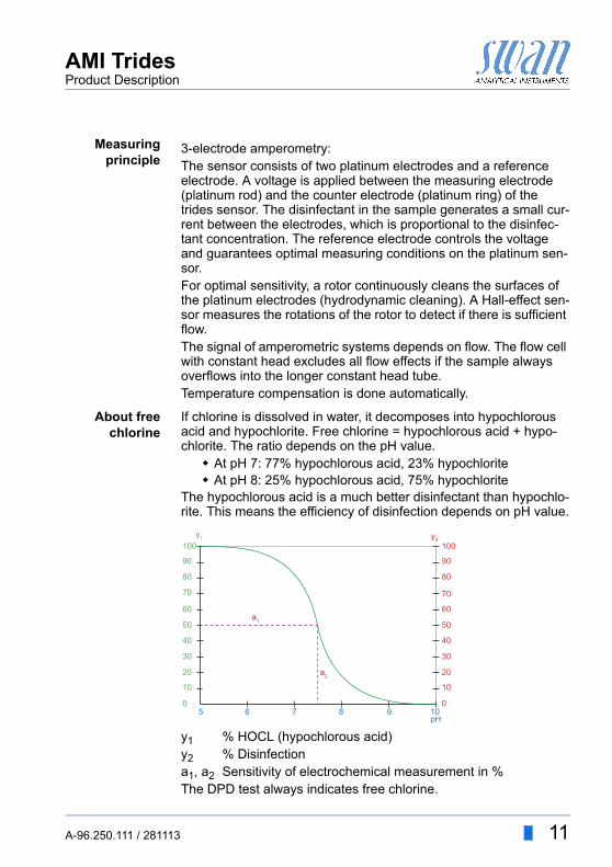
Measuringprinciple
3-electrode amperometry:The sensor consists of two platinum electrodes and a reference electrode. A voltage is applied between the measuring electrode (platinum rod) and the counter electrode (platinum ring) of the trides sensor. The disinfectant in the sample generates a small cur-rent between the electrodes, which is proportional to the disinfec-tant concentration. The reference electrode controls the voltage and guarantees optimal measuring conditions on the platinum sen-sor.For optimal sensitivity, a rotor continuously cleans the surfaces of the platinum electrodes (hydrodynamic cleaning). A Hall-effect sen-sor measures the rotations of the rotor to detect if there is sufficient flow.The signal of amperometric systems depends on flow. The flow cell with constant head excludes all flow effects if the sample always overflows into the longer constant head tube.Temperature compensation is done automatically.
About freechlorine
If chlorine is dissolved in water, it decomposes into hypochlorous acid and hypochlorite. Free chlorine = hypochlorous acid + hypo-chlorite. The ratio depends on the pH value. At pH 7: 77% hypochlorous acid, 23% hypochlorite At pH 8: 25% hypochlorous acid, 75% hypochlorite
The hypochlorous acid is a much better disinfectant than hypochlo-rite. This means the efficiency of disinfection depends on pH value.
y1 % HOCL (hypochlorous acid)y2 % Disinfectiona1, a2 Sensitivity of electrochemical measurement in %The DPD test always indicates free chlorine.
100y1
a1
a2
90
80
70
60
50
40
30
20
10
5 6 7 8 9 10pH
0
100y2
90
80
70
60
50
40
30
20
10
0
A-96.250.111 / 281113 11

AMI TridesProduct Description
Amperometric sensors measure mainly the hypochlorous acid. Therefore, the higher the pH value is, the lower the current of the sensor.A pH compensation of the sensor signal is necessary to be able to compare the value directly to the DPD method. For that select <Free chlorine> in menu 5.1.3 <Installation/Sensors/Disinf.> The pH must be measured by an optional pH electrode or be pro-grammed correctly.
Hypochlorousacid
If hypochlorous acid is chosen as disinfectant in 5.1.3, the pH com-pensation is switched off. The displayed values show the efficiency of disinfection. Only during correction, the value is shown as free chlorine and can be therefore directly compared to the manual DPD value.
Free Chlorine+ HOCl
If you program Free+HOCl (HOCl=hypochlorous acid) as disinfec-tant in 5.1.3 you can set the hypochlorous acid as parameter on the signal outputs. The displayed value will be free chlorine.
On-lineoperation
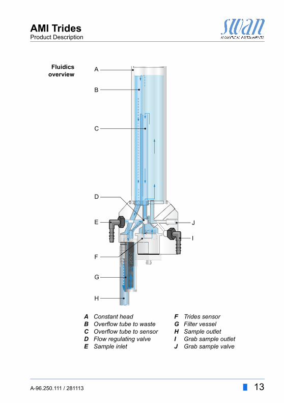
The sample enters at the sample inlet [E]. It passes the filter vessel [G] and the flow regulating valve [D], where the sample flow is ad-justed, and fills the constant head [A]. Sample must always over-flow via the overflow tube [B] into the waste to ensure constant pressure at the Trides sensor [F].A part of the sample flows through the overflow tube [C] to the Trides sensor [F], turns the rotor and leaves via sample outlet [H] into the waste. The rotation of the rotor is detected with a Hall-effect sensor to assure the sufficient sample flow. An inconsistent sample flow causes the rotor to turn slowly (or stop) and produces a system error.
Grab sample The grab sample outlet is used to take sample from the Trides con-stant head. This sample is used to make a comparison measure-ment with an other instrument.The standard method to correct the AMI Trides is the DPD photo-metric method. Use a high quality photometer to determine the ref-erence value, e.g. Swan Chematest 25.
12 A-96.250.111 / 281113
AMI TridesProduct Description
Fluidicsoverview
ABCDE
Constant headOverflow tube to wasteOverflow tube to sensorFlow regulating valveSample inlet
FGHIJ
Trides sensorFilter vesselSample outletGrab sample outletGrab sample valve
A
B
C
D
E
F
G
H
I
J
A-96.250.111 / 281113 13
AMI TridesProduct Description
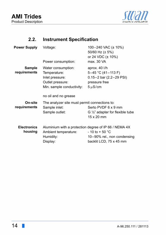
2.2. Instrument Specification
Power Supply Voltage: 100–240 VAC (± 10%)50/60 Hz (± 5%)or 24 VDC (± 10%)
Power consumption: max. 30 VA
Samplerequirements
Water consumption: aprox. 40 l/hTemperature: 5–45 °C (41–113 F)Inlet pressure: 0.15–2 bar (2.2–29 PSI)Outlet pressure: pressure freeMin. sample conductivity: 5 S/cm
no oil and no grease
On-siterequirements
The analyzer site must permit connections to:Sample inlet: Serto PVDF 6 x 9 mmSample outlet: G ½” adapter for flexible tube
15 x 20 mm
Electronicshousing
Aluminium with a protection degree of IP 66 / NEMA 4XAmbient temperature: - 10 to + 50 °CHumidity: 10–90% rel., non condensingDisplay: backlit LCD, 75 x 45 mm
14 A-96.250.111 / 281113
AMI TridesProduct Description
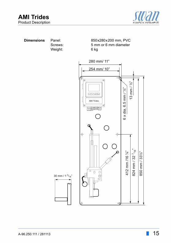
Dimensions Panel: 850x280x200 mm, PVCScrews: 5 mm or 6 mm diameterWeight: 6 kg
AMI Trides
850
mm
/ 33
½”
13 m
m /
½”
6 x
dia.
6.5
mm
/ ¼
”
254 mm/ 10”
280 mm/ 11”
412
mm
/16
¼”
824
mm
/ 32
7 / 16”
30 mm / 1 ”316/
A-96.250.111 / 281113 15
AMI TridesProduct Description
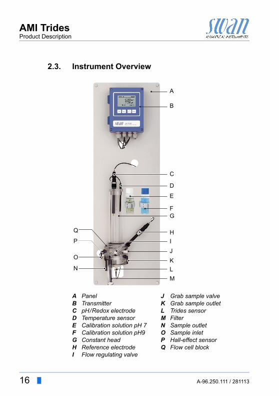
2.3. Instrument Overview
ABCDEFGHI
PanelTransmitterpH/Redox electrodeTemperature sensorCalibration solution pH 7Calibration solution pH9Constant headReference electrodeFlow regulating valve
JKLMNOPQ
Grab sample valveGrab sample outletTrides sensorFilterSample outletSample inletHall-effect sensorFlow cell block
A
B
C
D
E
F
I
KLM
N
P
Q
O
G
H
J
16 A-96.250.111 / 281113
AMI TridesInstallation
3. Installation
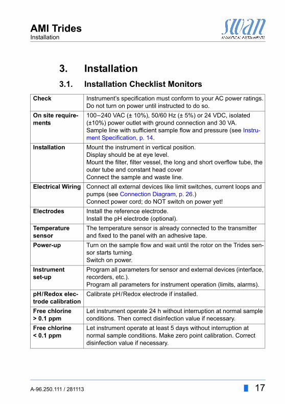
3.1. Installation Checklist Monitors
Check Instrument’s specification must conform to your AC power ratings. Do not turn on power until instructed to do so.
On site require-ments
100–240 VAC (± 10%), 50/60 Hz (± 5%) or 24 VDC, isolated (±10%) power outlet with ground connection and 30 VA.Sample line with sufficient sample flow and pressure (see Instru-ment Specification, p. 14.
Installation Mount the instrument in vertical position. Display should be at eye level.Mount the filter, filter vessel, the long and short overflow tube, theouter tube and constant head coverConnect the sample and waste line.
Electrical Wiring Connect all external devices like limit switches, current loops and pumps (see Connection Diagram, p. 26.)Connect power cord; do NOT switch on power yet!
Electrodes Install the reference electrode.Install the pH electrode (optional).
Temperature sensor
The temperature sensor is already connected to the transmitter and fixed to the panel with an adhesive tape.
Power-up Turn on the sample flow and wait until the rotor on the Trides sen-sor starts turning.Switch on power.
Instrument set-up
Program all parameters for sensor and external devices (interface, recorders, etc.). Program all parameters for instrument operation (limits, alarms).
pH/Redox elec-trode calibration
Calibrate pH/Redox electrode if installed.
Free chlorine > 0.1 ppm
Let instrument operate 24 h without interruption at normal sampleconditions. Then correct disinfection value if necessary.
Free chlorine < 0.1 ppm
Let instrument operate at least 5 days without interruption atnormal sample conditions. Make zero point calibration. Correctdisinfection value if necessary.
A-96.250.111 / 281113 17
AMI TridesInstallation
3.2. Mounting of Instrument Panel
The first part of this chapter describes the preparing and placing ofthe system for use. The instrument must only be installed by trained personnel. Mount the instrument in vertical position. For ease of operation mount it so that the display is at eye
level. For the installation a kit containing the following installation
material is available:– 6 Screws 6x60 mm– 6 Dowels– 6 Washers 6.4/12 mm
Mounting re-quirements
The instrument is only intended for indoor installation.For dimensions see Dimensions, p. 15.
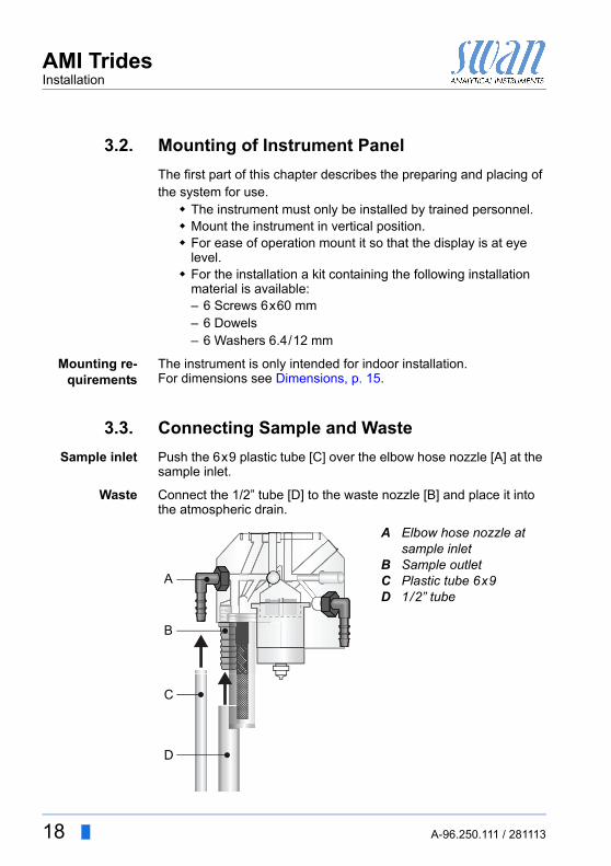
3.3. Connecting Sample and Waste
Sample inlet Push the 6x9 plastic tube [C] over the elbow hose nozzle [A] at the sample inlet.
Waste Connect the 1/2” tube [D] to the waste nozzle [B] and place it into the atmospheric drain.
A
BCD
Elbow hose nozzle at sample inletSample outletPlastic tube 6x91/2” tube
A
B
C
D
18 A-96.250.111 / 281113

AMI TridesInstallation
3.4. Install the Reference Electrode
The reference electrode is delivered separately and protected with a waterfilled protective cap. The connector is fixed to the panel with an adhesive tape and already connected to the front end PCB in the AMI transmitter.
To install the reference electrode proceed as follows:
1 Loosen the union nut [D].
2 Remove the protective cap [B] from the reference electrode [C].
3 Push the reference electrode through the union nut [D] into the bore of the flow cell block [E] as far as it will go.
4 Tighten the union nut.
5 Remove the connector [A] from the panel and screw it onto the reference electrode.
ABC
ConnectorProtective capReference sensor
DE
Union nutFlow cell block
C
B
DE
A
A-96.250.111 / 281113 19
AMI TridesInstallation
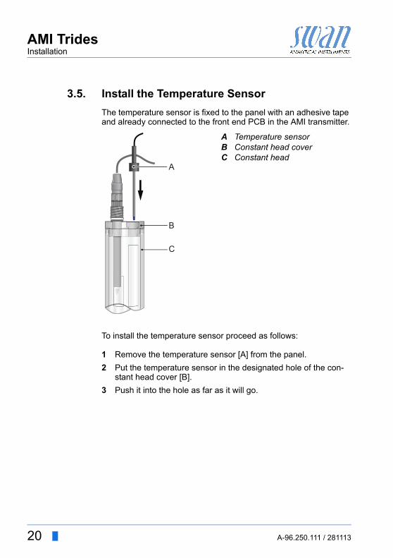
3.5. Install the Temperature Sensor
The temperature sensor is fixed to the panel with an adhesive tape and already connected to the front end PCB in the AMI transmitter.
To install the temperature sensor proceed as follows:
1 Remove the temperature sensor [A] from the panel.
2 Put the temperature sensor in the designated hole of the con-stant head cover [B].
3 Push it into the hole as far as it will go.
ABC
Temperature sensorConstant head coverConstant head
A
B
C
20 A-96.250.111 / 281113
AMI TridesInstallation
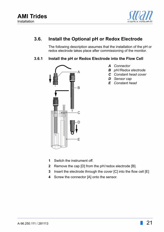
3.6. Install the Optional pH or Redox Electrode
The following description assumes that the installation of the pH or redox electrode takes place after commissioning of the monitor.
3.6.1 Install the pH or Redox Electrode into the Flow Cell
1 Switch the instrument off.
2 Remove the cap [D] from the pH/redox electrode [B].
3 Insert the electrode through the cover [C] into the flow cell [E]
4 Screw the connector [A] onto the sensor.
ABCDE
ConnectorpH/Redox electrodeConstant head coverSensor capConstant head
A
B
C
D
E
A-96.250.111 / 281113 21
AMI TridesInstallation
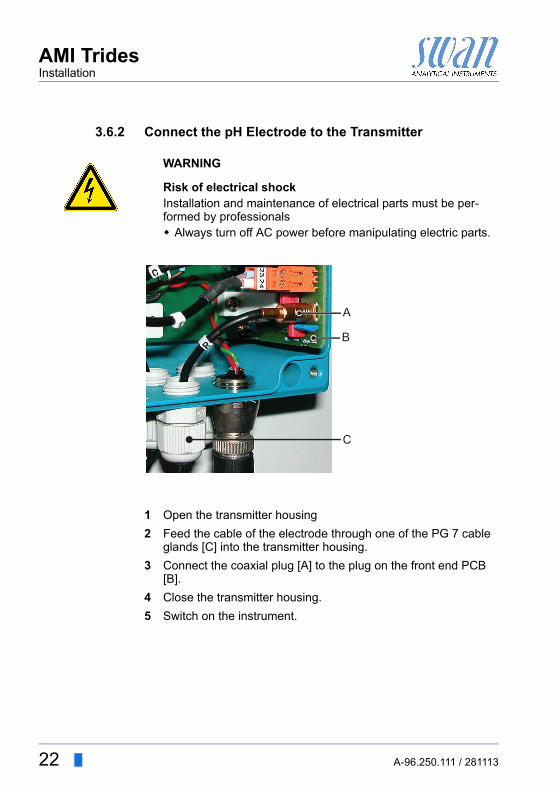
3.6.2 Connect the pH Electrode to the Transmitter
WARNING
Risk of electrical shockInstallation and maintenance of electrical parts must be per-formed by professionals Always turn off AC power before manipulating electric parts.
1 Open the transmitter housing
2 Feed the cable of the electrode through one of the PG 7 cable glands [C] into the transmitter housing.
3 Connect the coaxial plug [A] to the plug on the front end PCB [B].
4 Close the transmitter housing.
5 Switch on the instrument.
A
B
C
22 A-96.250.111 / 281113
AMI TridesInstallation
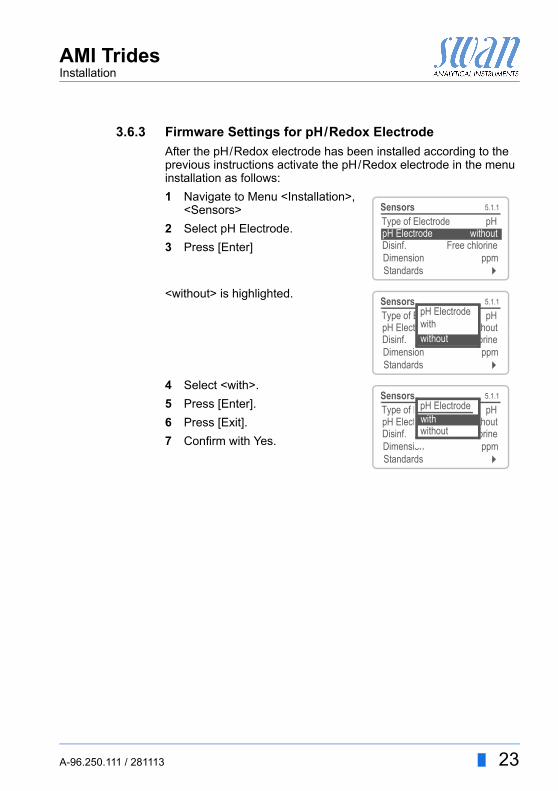
3.6.3 Firmware Settings for pH/Redox Electrode
After the pH/Redox electrode has been installed according to the previous instructions activate the pH/Redox electrode in the menu installation as follows:
1 Navigate to Menu <Installation>, <Sensors>
2 Select pH Electrode.
3 Press [Enter]
<without> is highlighted.
4 Select <with>.
5 Press [Enter].
6 Press [Exit].
7 Confirm with Yes.
5.1.1SensorsType of Electrode pH
Disinf. Free chlorineDimension ppmStandards
pH Electrode without
5.1.1SensorsType of Electrode pHpH Electrode withoutDisinf. Free chlorineDimension ppmStandards
pH Electrodewithwithout
5.1.1SensorsType of Electrode pHpH Electrode withoutDisinf. Free chlorineDimension ppmStandards
pH Electrode
withoutwith
A-96.250.111 / 281113 23
AMI TridesInstallation
3.7. Electrical Connections
WARNING
Electrical hazard. Always turn off AC power before manipulating electric parts. Grounding requirements: Only operate the instrument from
an power outlet which has a ground connection. Make sure the power specification of the instrument corre-
sponds to the power on site.
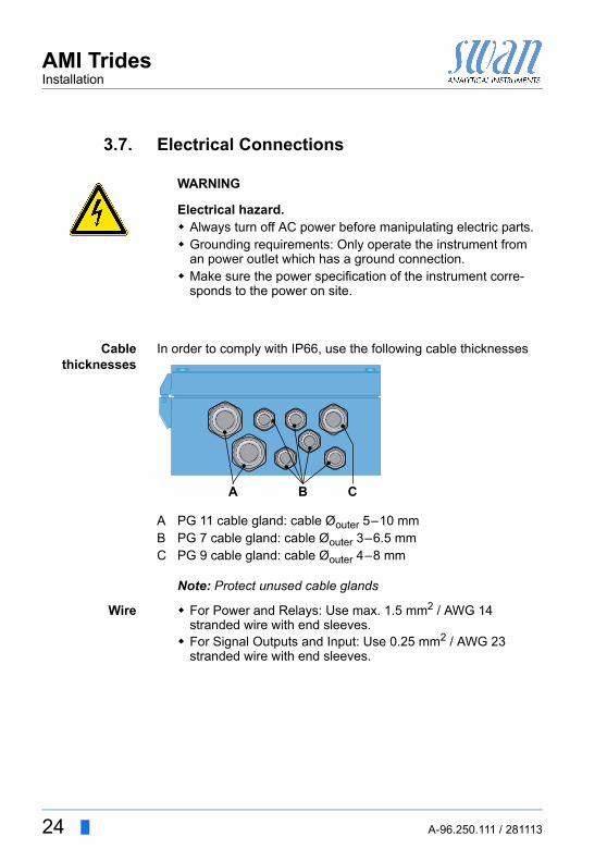
Cablethicknesses
In order to comply with IP66, use the following cable thicknesses
Note: Protect unused cable glands
Wire For Power and Relays: Use max. 1.5 mm2 / AWG 14 stranded wire with end sleeves.
For Signal Outputs and Input: Use 0.25 mm2 / AWG 23 stranded wire with end sleeves.
ABC
PG 11 cable gland: cable Øouter 5–10 mmPG 7 cable gland: cable Øouter 3–6.5 mmPG 9 cable gland: cable Øouter 4–8 mm
A B C
24 A-96.250.111 / 281113
AMI TridesInstallation
WARNING
External Voltage.External supplied devices connected to relay 1 or 2 or to the alarm relay can cause electrical shocks Make sure that the devices connected to the following con-
tacts are disconnected from the power before resuming in-stallation.– relay 1– relay 2– alarm relay
WARNING
To prevent from electrical shock, do not connect the instrument to the power unless the ground wire (PE) is connected. Do not connect unless specifically instructed to do so.
WARNING
The mains of the AMI Transmitter must be secured by a main switch and appropriate fuse or circuit breaker.
A-96.250.111 / 281113 25
AMI TridesInstallation
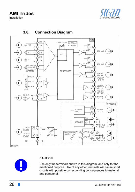
3.8. Connection Diagram
CAUTION
Use only the terminals shown in this diagram, and only for the mentioned purpose. Use of any other terminals will cause short circuits with possible corresponding consequences to material and personnel.
26 A-96.250.111 / 281113

AMI TridesInstallation
3.9. Power Supply
WARNING
Risk of electrical shockInstallation and maintenance of electrical parts must be per-formed by professionals Always turn off AC power before manipulating electric parts.
Note: The protective earth wire (Ground) has to be connected to the grounding terminal.
Installationrequirements
The installation must meet the following requirements. Fuse 1.6 AT Mains cable to comply with standards IEC 60227 or IEC
60245; flammable rating FV1 Mains equipped with an external switch or circuit-breaker
– near the instrument– easily accessible to the operator– marked as interrupter for AMI Trides
ABCD
Power supply connectorNeutral conductor, Terminal 2Phase conductor, Terminal 1Protective earth PE
A
BC
D
A-96.250.111 / 281113 27
AMI TridesInstallation
3.10. Input
Note:Use only potential-free (dry) contacts.
Terminals 16/42For programming see Input 5.3.4, p. 83.
3.11. Relay Contacts
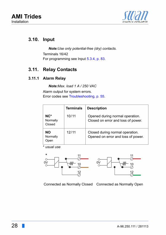
3.11.1 Alarm Relay
Note:Max. load 1 A / 250 VAC
Alarm output for system errors. Error codes see Troubleshooting, p. 55.
* usual use
Terminals Description
NC*Normally Closed
10/11 Opened during normal operation.Closed on error and loss of power.
NONormallyOpen
12/11 Closed during normal operation.Opened on error and loss of power.
Connected as Normally Closed Connected as Normally Open
10
12
11
0V
*
10
12
11
0V
28 A-96.250.111 / 281113
AMI TridesInstallation
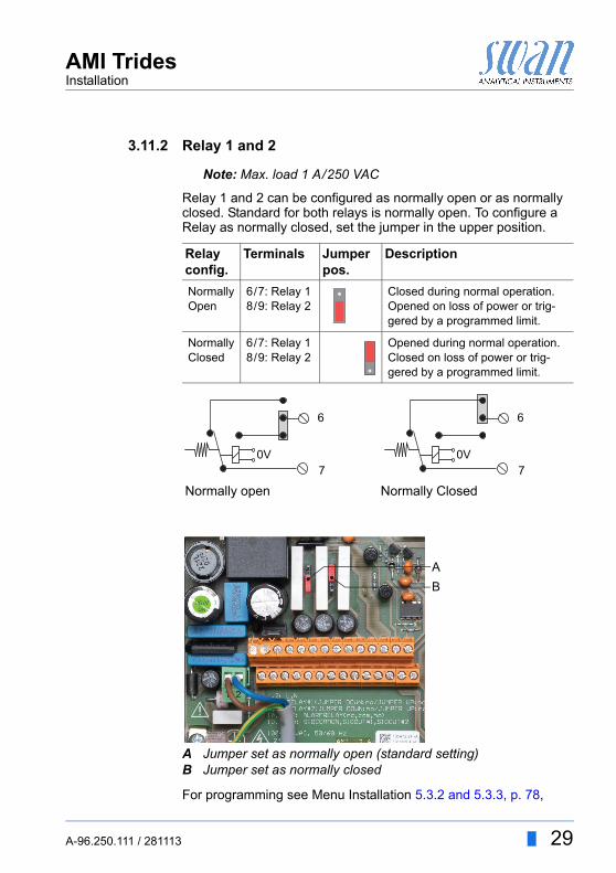
3.11.2 Relay 1 and 2
Note: Max. load 1 A/250 VAC
Relay 1 and 2 can be configured as normally open or as normally closed. Standard for both relays is normally open. To configure a Relay as normally closed, set the jumper in the upper position.
For programming see Menu Installation 5.3.2 and 5.3.3, p. 78,
Relay config.
Terminals Jumper pos.
Description
NormallyOpen
6/7: Relay 18/9: Relay 2
Closed during normal operation.Opened on loss of power or trig-gered by a programmed limit.
NormallyClosed
6/7: Relay 18/9: Relay 2
Opened during normal operation.Closed on loss of power or trig-gered by a programmed limit.
Normally open Normally Closed
AB
Jumper set as normally open (standard setting)Jumper set as normally closed
6
0V7
6
0V7
AB
A-96.250.111 / 281113 29
AMI TridesInstallation
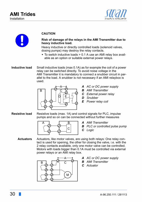
CAUTION
Risk of damage of the relays in the AMI Transmitter due to heavy inductive load.Heavy inductive or directly controlled loads (solenoid valves, dosing pumps) may destroy the relay contacts. To switch inductive loads > 0.1 A use an AMI relay box avail-
able as an option or suitable external power relays.
Inductive load Small inductive loads (max 0.1A) as for example the coil of a power relay can be switched directly. To avoid noise voltage in the AMI Transmitter it is mandatory to connect a snubber circuit in par-allel to the load. A snubber is not necessary if an AMI relaybox is used.
Resistive load Resistive loads (max. 1A) and control signals for PLC, impulse pumps and so on can be connected without further measures
Actuators Actuators, like motor valves, are using both relays: One relay con-tact is used for opening, the other for closing the valve, i.e. with the 2 relay contacts available, only one motor valve can be controlled. Motors with loads bigger than 0.1A must be controlled via external power relays or an AMI relay box.
ABCDE
AC or DC power supplyAMI TransmitterExternal power relaySnubberPower relay coil
AB C
D E
ABC
AMI TransmitterPLC or controlled pulse pumpLogic
A B
C
ABC
AC or DC power supplyAMI TransmitterActuator
M
AB C
30 A-96.250.111 / 281113
AMI TridesInstallation
3.12. Signal Outputs
3.12.1 Signal Output 1 and 2 (current outputs)
Note:Max. burden 510 If signals are sent to two different receivers, use signal isolator (loop isolator).
Signal output 1: Terminals 14 (+) and 13 (-)Signal output 2: Terminals 15 (+) and 13 (-)For programming see Program Overview, p. 61, Menu Installation
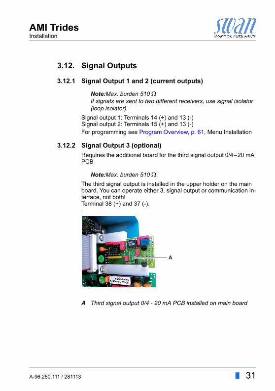
3.12.2 Signal Output 3 (optional)
Requires the additional board for the third signal output 0/4–20 mA PCB
Note:Max. burden 510 .
The third signal output is installed in the upper holder on the main board. You can operate either 3. signal output or communication in-terface, not both!Terminal 38 (+) and 37 (-)..
A Third signal output 0/4 - 20 mA PCB installed on main board
A
A-96.250.111 / 281113 31
AMI TridesInstallation
3.13. Interface
3.13.1 Interface RS232
Terminal 50, 52, 53The AMI Interface RS232 PCB is used for Logger down load and Firmware up load. For detailed information see the corresponding manual “AMI RS232 Interface”.
RS232 Interface PCB
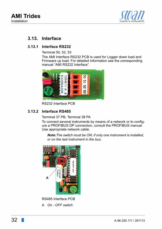
3.13.2 Interface RS485
Terminal 37 PB, Terminal 38 PATo connect several instruments by means of a network or to config-ure a PROFIBUS DP connection, consult the PROFIBUS manual. Use appropriate network cable.
Note:The switch must be ON, if only one instrument is installed, or on the last instrument in the bus.
RS485 Interface PCB
A On - OFF switch
PB-D
PV1 V5.5
ON
OFF
81.420.020Profibus
A
32 A-96.250.111 / 281113
AMI TridesInstallation
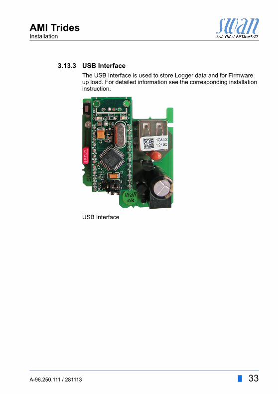
3.13.3 USB Interface
The USB Interface is used to store Logger data and for Firmware up load. For detailed information see the corresponding installation instruction.
USB Interface
A-96.250.111 / 281113 33
AMI TridesInstrument Setup
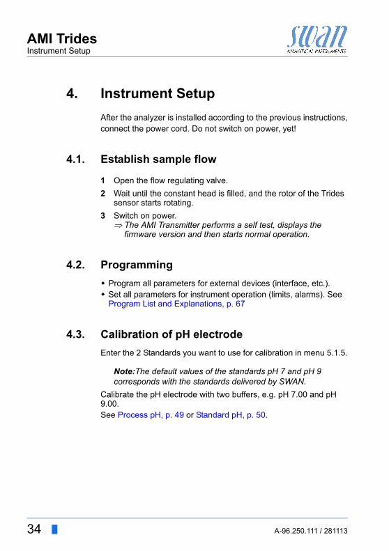
4. Instrument Setup
After the analyzer is installed according to the previous instructions,connect the power cord. Do not switch on power, yet!
4.1. Establish sample flow
1 Open the flow regulating valve.
2 Wait until the constant head is filled, and the rotor of the Trides sensor starts rotating.
3 Switch on power. The AMI Transmitter performs a self test, displays the
firmware version and then starts normal operation.
4.2. Programming
Program all parameters for external devices (interface, etc.). Set all parameters for instrument operation (limits, alarms). See
Program List and Explanations, p. 67
4.3. Calibration of pH electrode
Enter the 2 Standards you want to use for calibration in menu 5.1.5.
Note:The default values of the standards pH 7 and pH 9 corresponds with the standards delivered by SWAN.
Calibrate the pH electrode with two buffers, e.g. pH 7.00 and pH 9.00.See Process pH, p. 49 or Standard pH, p. 50.
34 A-96.250.111 / 281113
AMI TridesInstrument Setup
4.4. Correction of Trides sensor
If you measure concentrations > 0.1 ppm chlorine or 0.01 ppm ozone correct the instrument after 24 h running-in. A zero point cal-ibration is not necessary.The standard method to correct the AMI Trides sensor is the DPD photometric method. Use a high quality photometer (e.g. Swan Chematest 25), to determine the reference value. Perform 3 manu-al measurements and calculate the average value. The manual sample must be taken from the grab sample outlet of the flow cell.If you measure concentrations < 0.1 ppm chlorine or 0.01 ppm ozone, let the instrument run continuously for at least 5 days in nor-mal operation before performing a zero point calibration!
A-96.250.111 / 281113 35
AMI TridesOperation
5. Operation
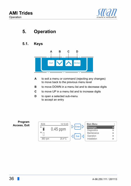
5.1. Keys
ProgramAccess, Exit
A to exit a menu or command (rejecting any changes)to move back to the previous menu level
B to move DOWN in a menu list and to decrease digits
C to move UP in a menu list and to increase digits
D to open a selected sub-menuto accept an entry
Exit Enter
B C DA
25.4°C
RUN
360 rpm
14:10:45R1
0.45 ppmR2
1
InstallationOperation
DiagnosticsMessages
Maintenance
Main MenuEnter
Exit
36 A-96.250.111 / 281113
AMI TridesOperation
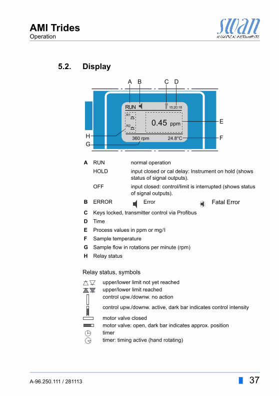
5.2. Display
Relay status, symbols
A RUN normal operation
HOLD input closed or cal delay: Instrument on hold (shows status of signal outputs).
OFF input closed: control/limit is interrupted (shows status of signal outputs).
B ERROR Error Fatal Error
C Keys locked, transmitter control via Profibus
D Time
E Process values in ppm or mg/l
F Sample temperature
G Sample flow in rotations per minute (rpm)
H Relay status
upper/lower limit not yet reachedupper/lower limit reachedcontrol upw./downw. no action
control upw./downw. active, dark bar indicates control intensity
motor valve closedmotor valve: open, dark bar indicates approx. positiontimertimer: timing active (hand rotating)
RUN 15:20:18
R1
R2
360 rpm 24.8°C
ppm0.45
A B
E
FGH
DC
A-96.250.111 / 281113 37
AMI TridesOperation
5.3. Software Structure
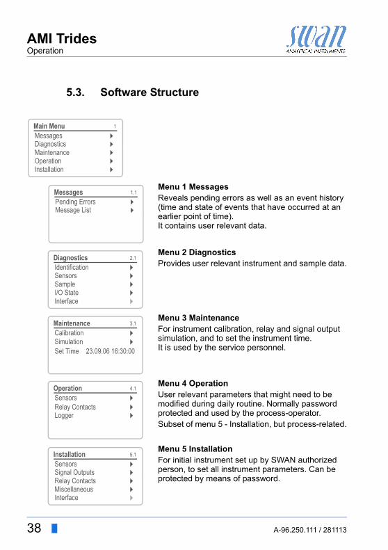
Menu 1 MessagesReveals pending errors as well as an event history (time and state of events that have occurred at an earlier point of time). It contains user relevant data.
Menu 2 DiagnosticsProvides user relevant instrument and sample data.
Menu 3 MaintenanceFor instrument calibration, relay and signal output simulation, and to set the instrument time. It is used by the service personnel.
Menu 4 OperationUser relevant parameters that might need to be modified during daily routine. Normally password protected and used by the process-operator.Subset of menu 5 - Installation, but process-related.
Menu 5 InstallationFor initial instrument set up by SWAN authorized person, to set all instrument parameters. Can be protected by means of password.
1
Messages
OperationMaintenanceDiagnostics
Main Menu
Installation
1.1
Pending ErrorsMessages
Message List
2.1
InterfaceI/O StateSample
IdentificationSensors
Diagnostics
3.1
CalibrationMaintenance
Set Time 23.09.06 16:30:00Simulation
4.1
LoggerRelay ContactsSensorsOperation
5.1
InterfaceMiscellaneousRelay Contacts
SensorsSignal Outputs
Installation
38 A-96.250.111 / 281113
AMI TridesOperation
5.4. Changing Parameters and values
Changingparameters
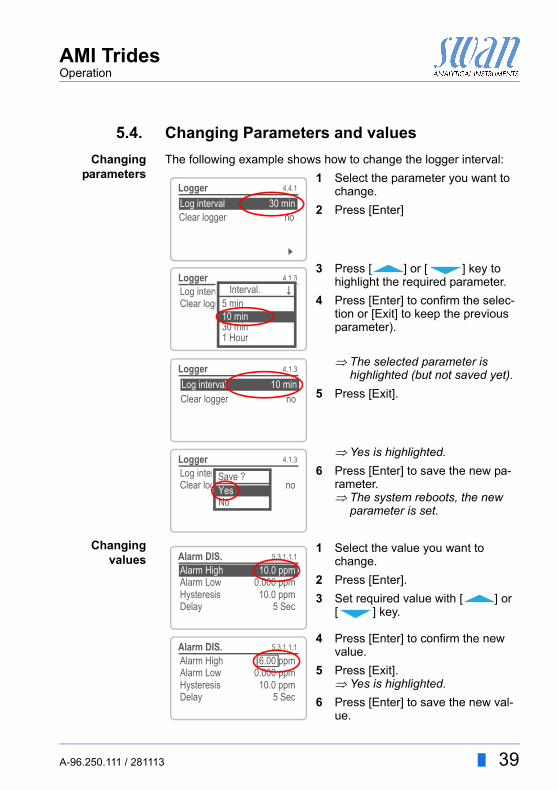
The following example shows how to change the logger interval:
Changingvalues
1 Select the parameter you want to change.
2 Press [Enter]
3 Press [ ] or [ ] key to highlight the required parameter.
4 Press [Enter] to confirm the selec-tion or [Exit] to keep the previous parameter).
The selected parameter is highlighted (but not saved yet).
5 Press [Exit].
Yes is highlighted.
6 Press [Enter] to save the new pa-rameter. The system reboots, the new
parameter is set.
5.1.2SensorsSensor type FOME
Temperature NT5KStandards
Disinf. Free chlorine
4.4.1Logger
Log interval 30 minClear logger no
4.1.3Logger
Clear logger noLog interval 30min
1 Hour
Interval.5 min
30 min10 min
4.1.3Logger
Log interval 10 minClear logger no
4.1.3LoggerLog intervalClear logger no
No
Save ?Yes
1 Select the value you want to change.
2 Press [Enter].
3 Set required value with [ ] or [ ] key.
4 Press [Enter] to confirm the new value.
5 Press [Exit]. Yes is highlighted.
6 Press [Enter] to save the new val-ue.
5.3.1.1.1
Alarm High 10.0 ppmAlarm DIS.
Alarm Low 0.000 ppmHysteresis 10.0 ppmDelay 5 Sec
5.3.1.1.1Alarm DIS.
Alarm Low 0.000 ppmHysteresis 10.0 ppmDelay 5 Sec
Alarm High 6.00 ppm
A-96.250.111 / 281113 39

AMI TridesMaintenance
6. Maintenance
Some countries have there own national regulations for inspection of analyzers.If no such regulations exist, proceed according the table below.
WARNING
Stop operation before maintenance. Stop sample flow. Shut off power of the instrument.
6.1. Maintenance Schedule
Preventive maintenance frequency depends on water quality, on the application, and on national regulations.Control of certain set-point: Swimming pools, sanitary water:
Daily up toevery 2 weeks
Check sample supply for dirt.Clean all filters and strainers, if necessary.Clean AMI Trides protection filter, if necessary.Check sample flow.
Weekly (some countries daily)
Option pH/Redox: Perform Process pH/Redox.Determine disinfectant value by manual DPD analysis and, if necessary, perform Process Trides.
Every 2 months
Option pH/Redox: Perform pH/Redox calibration.
3–4 Years Replace the reference electrode.
40 A-96.250.111 / 281113
AMI TridesMaintenance
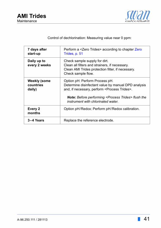
Control of dechlorination: Measuring value near 0 ppm:
7 days after start-up
Perform a <Zero Trides> according to chapter Zero Trides, p. 51
Daily up toevery 2 weeks
Check sample supply for dirt.Clean all filters and strainers, if necessary.Clean AMI Trides protection filter, if necessary.Check sample flow.
Weekly (some countries daily)
Option pH: Perform Process pH.Determine disinfectant value by manual DPD analysis and, if necessary, perform <Process Trides>.
Note: Before performing <Process Trides> flush the instrument with chlorinated water.
Every 2 months
Option pH/Redox: Perform pH/Redox calibration.
3–4 Years Replace the reference electrode.
A-96.250.111 / 281113 41
AMI TridesMaintenance
6.2. Cleaning of Trides protective filter
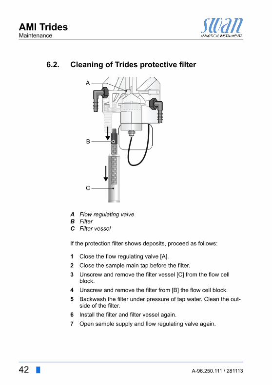
If the protection filter shows deposits, proceed as follows:
1 Close the flow regulating valve [A].
2 Close the sample main tap before the filter.
3 Unscrew and remove the filter vessel [C] from the flow cell block.
4 Unscrew and remove the filter from [B] the flow cell block.
5 Backwash the filter under pressure of tap water. Clean the out-side of the filter.
6 Install the filter and filter vessel again.
7 Open sample supply and flow regulating valve again.
ABC
Flow regulating valveFilterFilter vessel
A
B
C
42 A-96.250.111 / 281113
AMI TridesMaintenance
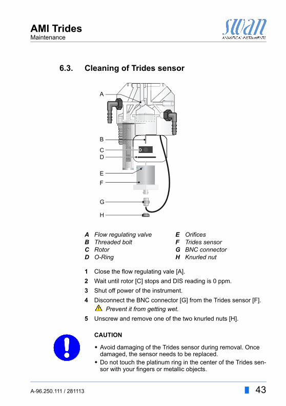
6.3. Cleaning of Trides sensor
1 Close the flow regulating vale [A].
2 Wait until rotor [C] stops and DIS reading is 0 ppm.
3 Shut off power of the instrument.
4 Disconnect the BNC connector [G] from the Trides sensor [F].
Prevent it from getting wet.
5 Unscrew and remove one of the two knurled nuts [H].
CAUTION
Avoid damaging of the Trides sensor during removal. Once damaged, the sensor needs to be replaced.
Do not touch the platinum ring in the center of the Trides sen-sor with your fingers or metallic objects.
ABCD
Flow regulating valveThreaded boltRotorO-Ring
EFGH
OrificesTrides sensorBNC connectorKnurled nut
A
B
C
G
F
H
D
E
A-96.250.111 / 281113 43
AMI TridesMaintenance
6 Hold the Trides sensor [F] with one hand while unscrewing and removing the 2nd knurled nut.
7 Remove the Trides sensor from the flow cell.
Take care not to spill the sample remaining in the sensor.
8 Remove the rotor [C] from the Trides sensor.
9 Clean the tow orifices [E] with a pipe cleaner.
WARNING
Hydrochloric acid.Hydrochloric acid may be used to remove strong calcareous de-posits. Hydrochloric acid causes severe skin burns and eye damage. Carefully read the Safety Data Sheet before handling hydro-
chloric acid
Cleaning 1 Clean the rotor with a soft tissue.
2 Cautiously wipe the sensor with a soft tissue, mainly the plati-num parts and the whole area which is in contact with water.If necessary, strong calcareous deposits can be eliminated with 1% hydrochloric acid.
3 After cleaning rinse all parts well with clean water
Install 1 Put rotor on the sensor.
2 Install the Trides sensor into the flow cell.
3 Fasten the knurled nuts hand-tight.
4 Connect the BNC connector to the Trides sensor.
5 Open the sample flow.
6 As soon as the rotor is turning, switch on power.
Note: After cleaning the sensor, the measuring value may be too high. Let the instrument run for about 24 h.
44 A-96.250.111 / 281113
AMI TridesMaintenance
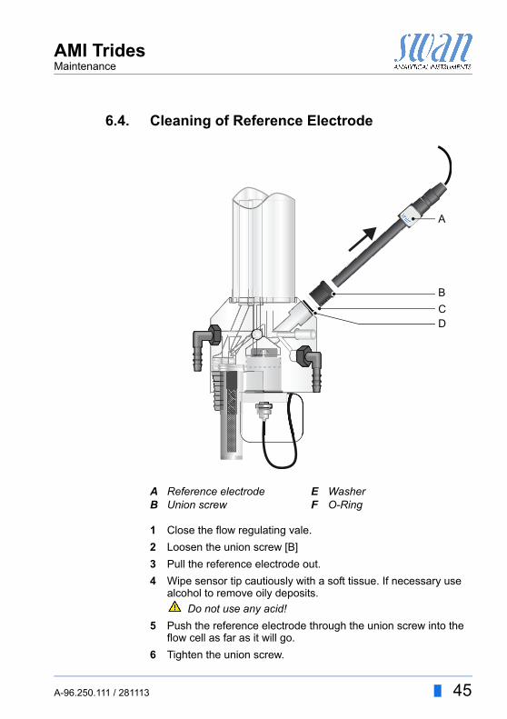
6.4. Cleaning of Reference Electrode
1 Close the flow regulating vale.
2 Loosen the union screw [B]
3 Pull the reference electrode out.
4 Wipe sensor tip cautiously with a soft tissue. If necessary use alcohol to remove oily deposits.
Do not use any acid!
5 Push the reference electrode through the union screw into the flow cell as far as it will go.
6 Tighten the union screw.
AB
Reference electrodeUnion screw
EF
WasherO-Ring
CD
B
A
A-96.250.111 / 281113 45
AMI TridesMaintenance
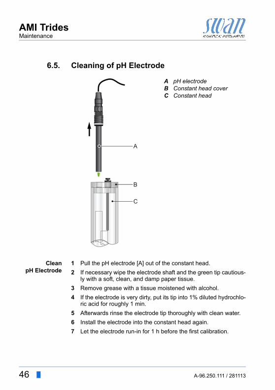
6.5. Cleaning of pH Electrode
CleanpH Electrode
1 Pull the pH electrode [A] out of the constant head.
2 If necessary wipe the electrode shaft and the green tip cautious-ly with a soft, clean, and damp paper tissue.
3 Remove grease with a tissue moistened with alcohol.
4 If the electrode is very dirty, put its tip into 1% diluted hydrochlo-ric acid for roughly 1 min.
5 Afterwards rinse the electrode tip thoroughly with clean water.
6 Install the electrode into the constant head again.
7 Let the electrode run-in for 1 h before the first calibration.
ABC
pH electrodeConstant head coverConstant head
A
B
C
46 A-96.250.111 / 281113
AMI TridesMaintenance
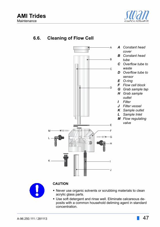
6.6. Cleaning of Flow Cell
CAUTION
Never use organic solvents or scrubbing materials to clean acrylic glass parts.
Use soft detergent and rinse well. Eliminate calcareous de-posits with a common household deliming agent in standard concentration.
A
B
C
D
EFGH
IJKLM
Constant head coverConstant head tubeOverflow tube to wasteOverflow tube to sensorO-ringFlow cell blockGrab sample tapGrab sample outletFilterFilter vesselSample outletSample InletFlow regulating valve
C
D
F
G
J
K
L
M
H
I
E
B
A
A-96.250.111 / 281113 47
AMI TridesMaintenance
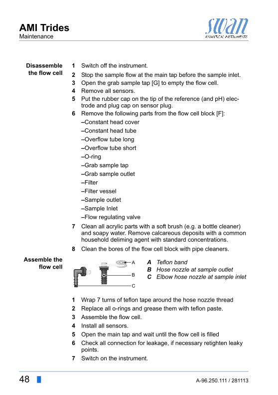
Disassemblethe flow cell
1 Switch off the instrument.
2 Stop the sample flow at the main tap before the sample inlet.3 Open the grab sample tap [G] to empty the flow cell.4 Remove all sensors.5 Put the rubber cap on the tip of the reference (and pH) elec-
trode and plug cap on sensor plug.6 Remove the following parts from the flow cell block [F]:
–Constant head cover
–Constant head tube
–Overflow tube long
–Overflow tube short
–O-ring
–Grab sample tap
–Grab sample outlet
–Filter
–Filter vessel
–Sample outlet
–Sample Inlet
–Flow regulating valve
7 Clean all acrylic parts with a soft brush (e.g. a bottle cleaner) and soapy water. Remove calcareous deposits with a common household deliming agent with standard concentrations.
8 Clean the bores of the flow cell block with pipe cleaners.
Assemble theflow cell
1 Wrap 7 turns of teflon tape around the hose nozzle thread
2 Replace all o-rings and grease them with teflon paste.
3 Assemble the flow cell.
4 Install all sensors.
5 Open the main tap and wait until the flow cell is filled
6 Check all connection for leakage, if necessary retighten leaky points.
7 Switch on the instrument.
ABC
Teflon bandHose nozzle at sample outletElbow hose nozzle at sample inlet
C
B
A
48 A-96.250.111 / 281113
AMI TridesMaintenance
6.7. Calibration of Trides Sensor
The following description of the calibration procedure assumes, that the AMI Trides is equipped with a pH electrode. In case your AMI Trides has no pH electrode, skip the pH calibration.
6.7.1 Process pH
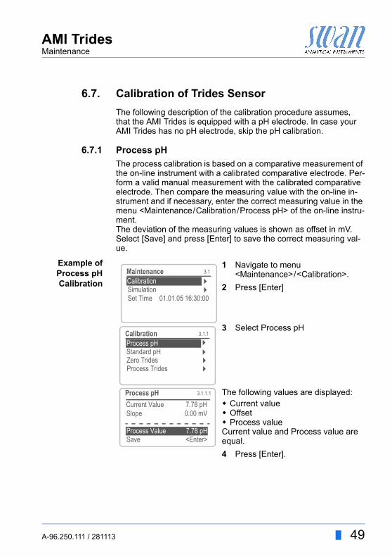
The process calibration is based on a comparative measurement of the on-line instrument with a calibrated comparative electrode. Per-form a valid manual measurement with the calibrated comparative electrode. Then compare the measuring value with the on-line in-strument and if necessary, enter the correct measuring value in the menu <Maintenance/Calibration/Process pH> of the on-line instru-ment. The deviation of the measuring values is shown as offset in mV. Select [Save] and press [Enter] to save the correct measuring val-ue.
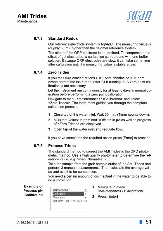
Example ofProcess pHCalibration
1 Navigate to menu <Maintenance>/<Calibration>.
2 Press [Enter]
3 Select Process pH
The following values are displayed: Current value Offset Process valueCurrent value and Process value are equal.
4 Press [Enter].
3.1
CalibrationSimulation
Maintenance
Set Time 01.01.05 16:30:00
Calibration
3.1.1
Standard pH
Calibration
Zero Trides
Process pH
Process Trides
Process pH
Slope 0.00 mV
Save <Enter>Process Value 7.78 pH
3.1.1.1
Current Value 7.78 pH
A-96.250.111 / 281113 49
AMI TridesMaintenance
6.7.2 Standard pH
StandardpH Calibration
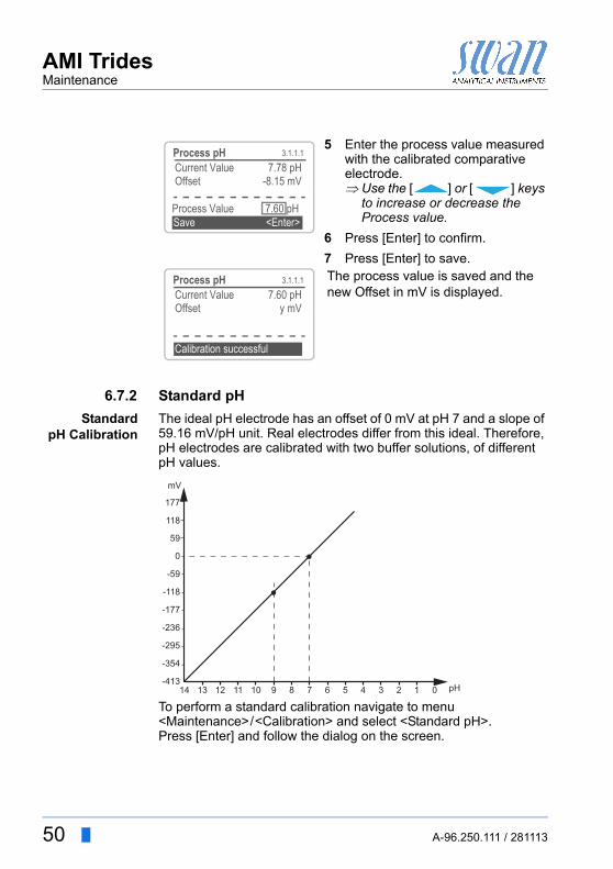
The ideal pH electrode has an offset of 0 mV at pH 7 and a slope of 59.16 mV/pH unit. Real electrodes differ from this ideal. Therefore, pH electrodes are calibrated with two buffer solutions, of different pH values.
.
To perform a standard calibration navigate to menu <Maintenance>/<Calibration> and select <Standard pH>. Press [Enter] and follow the dialog on the screen.
5 Enter the process value measured with the calibrated comparative electrode. Use the [ ] or [ ] keys
to increase or decrease the Process value.
6 Press [Enter] to confirm.
7 Press [Enter] to save.The process value is saved and the new Offset in mV is displayed.
3.1.1.1Process pHCurrent Value 7.78 pHOffset -8.15 mV
Process Value 7.60 pHSave <Enter>
3.1.1.1Process pHCurrent Value 7.60 pHOffset y mV
Calibration successful
pH14 13 12 11 10 9 8 7 6 5 4 3 2 1 0
0
-59
59
-118
118
-177
177
-236
-295
-354
-413
mV
50 A-96.250.111 / 281113
AMI TridesMaintenance
6.7.3 Standard Redox
Our reference electrode system is Ag/AgCl. The measuring value is roughly 50 mV higher than the calomel reference system.The slope of the ORP electrode is not defined. To compensate the offset of gel electrodes, a calibration can be done with one buffer solution. Because ORP electrodes are slow, it can take some time after calibration until the measuring value is stable again.
6.7.4 Zero Trides
If you measure concentrations > 0.1 ppm chlorine or 0.01 ppm ozone correct the instrument after 24 h running-in. A zero point cal-ibration is not necessary.Let the instrument run continuously for at least 5 days in normal op-eration before performing a zero point calibration!Navigate to menu <Maintenance>/<Calibration> and select <Zero Trides>. The instrument guides you through the complete calibration process.
1 Close tap of the water inlet. Wait 30 min. (Timer counts down).
2 <Current Value> in ppm and <Offset> in µA as well as progress of <Zero Trides> are displayed
3 Open tap of the water inlet and regulate flow.
If you have completed the required action press [Enter] to proceed.
6.7.5 Process Trides
The standard method to correct the AMI Trides is the DPD photo-metric method. Use a high quality photometer to determine the ref-erence value, e.g. Swan Chematest 25. Take the sample from the grab sample outlet of the AMI Trides and perform 3 manual measurements. Then calculate the average val-ue and use it to for comparison.You need a certain amount of disinfectant in the water to be able to do a correction.
Example ofProcess pHCalibration
1 Navigate to menu <Maintenance>/<Calibration>.
2 Press [Enter]
3.1
CalibrationSimulation
Maintenance
Set Time 01.01.05 16:30:00
Calibration
A-96.250.111 / 281113 51
AMI TridesMaintenance
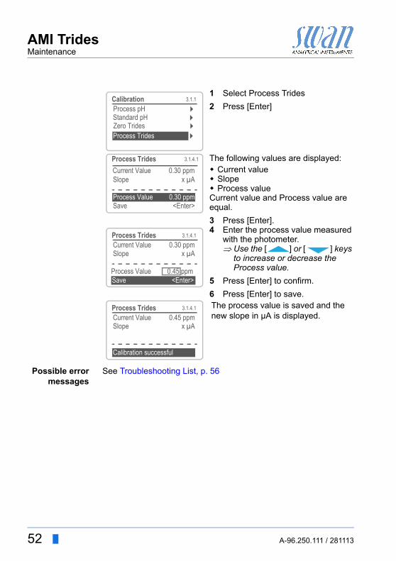
Possible errormessages
See Troubleshooting List, p. 56
1 Select Process Trides
2 Press [Enter]
The following values are displayed: Current value Slope Process valueCurrent value and Process value are equal.
3 Press [Enter].4 Enter the process value measured
with the photometer. Use the [ ] or [ ] keys
to increase or decrease the Process value.
5 Press [Enter] to confirm.
6 Press [Enter] to save.The process value is saved and the new slope in µA is displayed.
3.1.1
Standard pH
Calibration
Zero TridesProcess Trides
Process pH
Process Trides
Slope x µA
Save <Enter>Process Value 0.30 ppm
3.1.4.1
Current Value 0.30 ppm
3.1.4.1Process TridesCurrent Value 0.30 ppmSlope x µA
Process Value 0.45 ppmSave <Enter>
3.1.4.1Process TridesCurrent Value 0.45 ppmSlope x µA
Calibration successful
52 A-96.250.111 / 281113
AMI TridesMaintenance
6.8. Replacing Fuses
WARNING
External Voltage.External supplied devices connected to relay 1 or 2 or to the alarm relay can cause electrical shocks Make sure that the devices connected to the following
contacts are disconnected from the power before resum-ing installation.– relay 1– relay 2– alarm relay
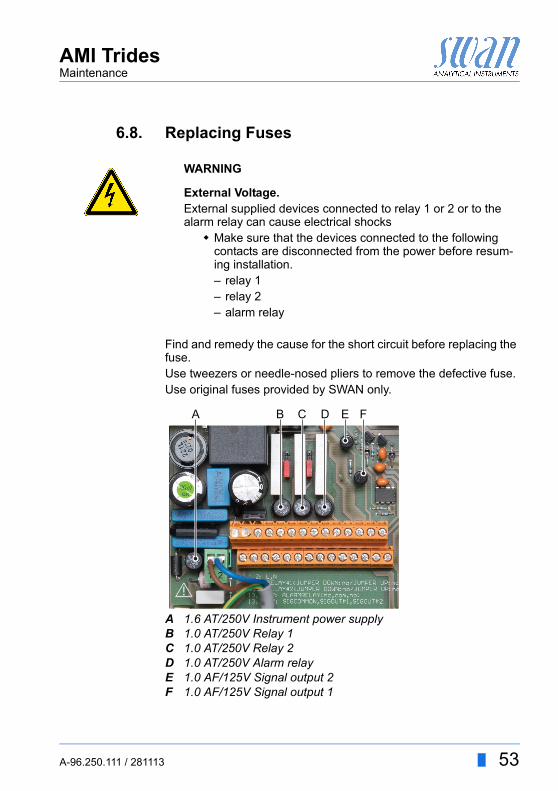
Find and remedy the cause for the short circuit before replacing the fuse.Use tweezers or needle-nosed pliers to remove the defective fuse.Use original fuses provided by SWAN only.
ABCDEF
1.6 AT/250V Instrument power supply1.0 AT/250V Relay 11.0 AT/250V Relay 21.0 AT/250V Alarm relay1.0 AF/125V Signal output 21.0 AF/125V Signal output 1
A B C D E F
A-96.250.111 / 281113 53
AMI TridesMaintenance
6.9. Longer Stop of Operation
Do not switch the instrument off if your operation is suspended for less than a week. Power consumption is very low, and the sensors remain ready for use.If water hardness is very high, calcium may precipitate.
1 Close sample flow regulating valve first.
2 Stop the sample flow at the main tap before the sample inlet.
3 Wait until the rotor has stopped turning and no disinfectant is displayed any more.
4 Switch off power of the instrument and of all other connected devices.
5 Open the grab sample tap to empty the flow cell.
6 Unscrew and remove the filter vessel from the flow cell block, empty and dry it, then screw it onto the flow cell block again.
7 If installed, remove the pH/Redox electrode from the constant head, fill 3-molar KCl (if not available, water) in the protective cap and put it on the electrode tip.
8 Loosen the connector from the pH/Redox electrode and put the connector cap on the electrode plug. Store it dry and frost pro-tected with tip pointing downwards.
9 Remove the reference electrode from the flow cell block, fill wa-ter in the protective cap and put the protective cap on the elec-trode tip.
10 Loosen the connector from the reference electrode and put the connector cap on the pH electrode plug. Store it dry and frost protected with tip pointing downwards.
11 Remove the BNC connector from the Trides sensor.
12 Unscrew and remove one of the two knurled nuts.
13 Hold the Trides sensor with one hand while unscrewing and re-moving the 2nd knurled nut.
14 Remove the Trides sensor from the flow cell.
15 Dry it with a soft, clean tissue, and store dry.
54 A-96.250.111 / 281113
AMI TridesTroubleshooting
7. Troubleshooting
This chapter provides some hints to make trouble shooting easier. For any detailed information how to replace or clean parts please see chapter Maintenance.For any detailed information how to program the instrument please see chapter Displays, Keys.Attention: The sample for the manual measurement (with DPD!) must be taken directly from the flow cell!If you need further help please contact your dealer. Note serial number of instrument and all diagnostic values before.
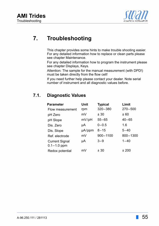
7.1. Diagnostic Values
Parameter Unit Typical Limit
Flow measurement rpm 320–380 270–500
pH Zero mV ± 30 ± 60
pH Slope mV/pH 55–65 40–65
Dis. Zero µA 0–0.5 1.6
Dis. Slope µA/ppm 8–15 5–40
Ref. electrode mV 900–1100 800–1300
Current Signal0.1–1.0 ppm
µA 3–9 1–40
Redox potential mV ± 30 ± 200
A-96.250.111 / 281113 55
AMI TridesTroubleshooting
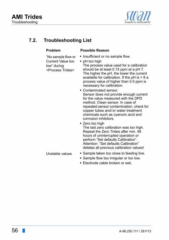
7.2. Troubleshooting List
Problem Possible Reason
“No sample flow or Current Value too low” during<Process Trides>
Insufficient or no sample flow. pH too high
The process value used for a calibration should be at least 0.15 ppm at a pH 7.The higher the pH, the lower the current available for calibration. If the pH is > 8 a process value of higher than 0.5 ppm is necessary for calibration.
Contaminated sensor.Sensor does not provide enough current for the value measured with the DPD method. Clean sensor. In case of repeated sensor contamination, check for copper tubes and/or water treatment chemicals such as cyanuric acid and corrosion inhibitors.
Zero too highThe last zero calibration was too high. Repeat the Zero Trides after min. 48 hours of uninterrupted operation or perform “Set defaults Calibration”.Attention: “Set defaults Calibration” deletes all previous calibration values!
Unstable values Sample taken too close to feeding line. Sample flow too irregular or too low. Electrode cable broken or wet.
56 A-96.250.111 / 281113
AMI TridesTroubleshooting
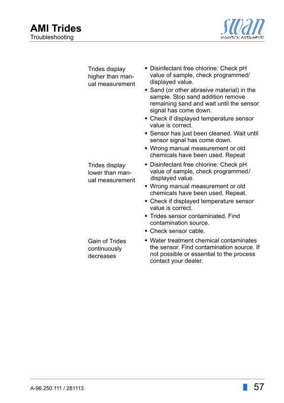
Trides display higher than man-ual measurement
Disinfectant free chlorine: Check pH value of sample, check programmed/displayed value.
Sand (or other abrasive material) in the sample. Stop sand addition remove remaining sand and wait until the sensor signal has come down.
Check if displayed temperature sensor value is correct.
Sensor has just been cleaned. Wait until sensor signal has come down.
Wrong manual measurement or old chemicals have been used. Repeat
Trides display lower than man-ual measurement
Disinfectant free chlorine: Check pH value of sample, check programmed/displayed value.
Wrong manual measurement or old chemicals have been used. Repeat.
Check if displayed temperature sensor value is correct.
Trides sensor contaminated. Find contamination source.
Check sensor cable.
Gain of Trides continuously decreases
Water treatment chemical contaminates the sensor. Find contamination source. If not possible or essential to the process contact your dealer.
A-96.250.111 / 281113 57
AMI TridesTroubleshooting
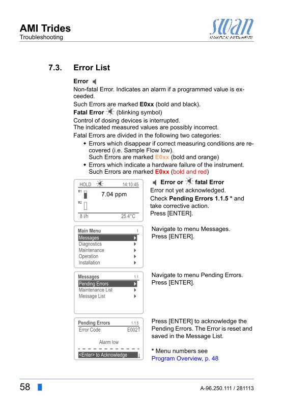
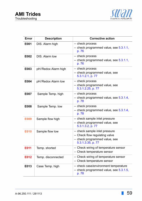
7.3. Error List
Error Non-fatal Error. Indicates an alarm if a programmed value is ex-ceeded.Such Errors are marked E0xx (bold and black).Fatal Error (blinking symbol)Control of dosing devices is interrupted.The indicated measured values are possibly incorrect.Fatal Errors are divided in the following two categories: Errors which disappear if correct measuring conditions are re-
covered (i.e. Sample Flow low).Such Errors are marked E0xx (bold and orange)
Errors which indicate a hardware failure of the instrument.Such Errors are marked E0xx (bold and red)
Error or fatal ErrorError not yet acknowledged.Check Pending Errors 1.1.5 * and take corrective action.Press [ENTER].
Navigate to menu Messages.Press [ENTER].
Navigate to menu Pending Errors.Press [ENTER].
Press [ENTER] to acknowledge the Pending Errors. The Error is reset and saved in the Message List.
* Menu numbers see Program Overview, p. 48
25.4°C
HOLD
8 l/h
14:10:45R1
7.04 ppmR2
1
InstallationOperation
DiagnosticsMessages
Maintenance
Main Menu
1.1
Message List
Pending ErrorsMaintenance List
Messages
1.1.5Pending ErrorsError Code E002
Alarm low
<Enter> to Acknowledge
58 A-96.250.111 / 281113
AMI TridesTroubleshooting
Error Description Corrective action
E001 DIS. Alarm high – check process– check programmed value, see 5.3.1.1,
p. 76
E002 DIS. Alarm low – check process– check programmed value, see 5.3.1.1,
p. 76
E003 pH/Redox Alarm high – check process– check programmed value, see
5.3.1.2.1, p. 77
E004 pH/Redox Alarm low – check process– check programmed value, see
5.3.1.2.25, p. 77
E007 Sample Temp. high – check process– check programmed value, see 5.3.1.4,
p. 78
E008 Sample Temp. low – check process– check programmed value, see 5.3.1.4,
p. 78
E009 Sample flow high – check sample inlet pressure– check programmed value, see
5.3.1.3.2, p. 77
E010 Sample flow low – check sample inlet pressure– Check flow regulating valve– check programmed value, see
5.3.1.3.35, p. 77
E011 Temp. shorted – Check wiring of temperature sensor– Check temperature sensor
E012 Temp. disconnected – Check wiring of temperature sensor– Check temperature sensor
E013 Case Temp. high – check case/environment temperature– check programmed value, see 5.3.1.5,
p. 78
A-96.250.111 / 281113 59

AMI TridesTroubleshooting
E014 Case Temp. low – check case/environment temperature– check programmed value, see 5.3.1.6,
p. 78
E015 TRIDES Reference – Check if conductivity value of sample is > 5 µS/cm.
– Calculate: actual Trides signal / average value 3 DPD meas. = must be >2 µA/ppm. If not, clean Trides sensor.
– Exchange reference electrode.
E024 Input active – See If Fault Yes is programmed in Menu see 5.3.4, p. 83
E025 IC MK41T56 – call service
E026 IC LM75 – call service
E027 IC PCF8574 – call service
E028 EEProm Microcon – call service
E029 EEProm Motherboard – call service
E030 EEProm Frontend – call service
E031 Cal. Recout – call service
E032 Wrong Frontend – call service
E033 Power-on – none, normal status
E034 Power-down – none, normal status
Error Description Corrective action
60 A-96.250.111 / 281113
AMI TridesProgram Overview
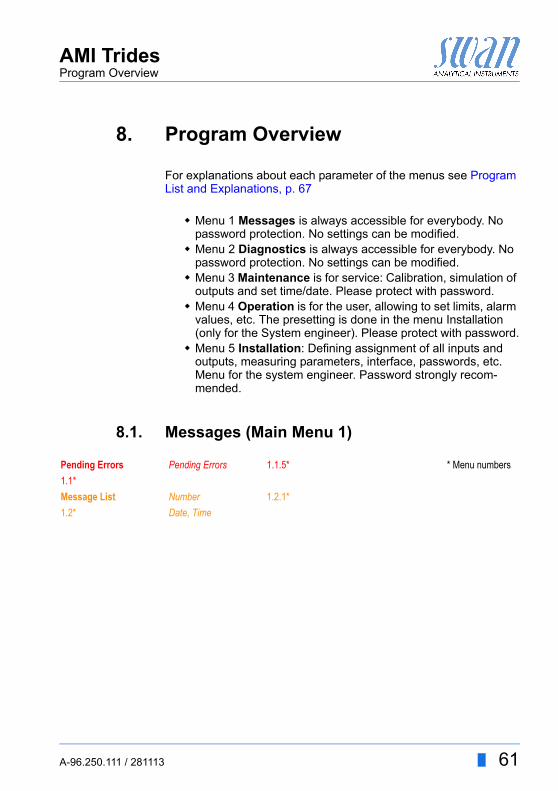
8. Program Overview
For explanations about each parameter of the menus see Program List and Explanations, p. 67
Menu 1 Messages is always accessible for everybody. No password protection. No settings can be modified.
Menu 2 Diagnostics is always accessible for everybody. No password protection. No settings can be modified.
Menu 3 Maintenance is for service: Calibration, simulation of outputs and set time/date. Please protect with password.
Menu 4 Operation is for the user, allowing to set limits, alarm values, etc. The presetting is done in the menu Installation (only for the System engineer). Please protect with password.
Menu 5 Installation: Defining assignment of all inputs and outputs, measuring parameters, interface, passwords, etc. Menu for the system engineer. Password strongly recom-mended.
8.1. Messages (Main Menu 1)
Pending Errors Pending Errors 1.1.5* * Menu numbers
1.1*
Message List Number 1.2.1*
1.2* Date, Time
A-96.250.111 / 281113 61
AMI TridesProgram Overview
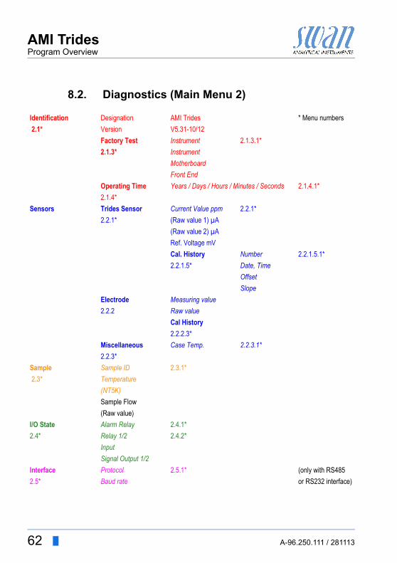
8.2. Diagnostics (Main Menu 2)
Identification Designation AMI Trides * Menu numbers
2.1* Version V5.31-10/12
Factory Test Instrument 2.1.3.1*
2.1.3* Instrument
Motherboard
Front End
Operating Time Years / Days / Hours / Minutes / Seconds 2.1.4.1*
2.1.4*
Sensors Trides Sensor Current Value ppm 2.2.1*
2.2.1* (Raw value 1) µA
(Raw value 2) µA
Ref. Voltage mV
Cal. History Number 2.2.1.5.1*
2.2.1.5* Date, Time
Offset
Slope
Electrode Measuring value
2.2.2 Raw value
Cal History
2.2.2.3*
Miscellaneous Case Temp. 2.2.3.1*
2.2.3*
Sample Sample ID 2.3.1*
2.3* Temperature
(NT5K)
Sample Flow
(Raw value)
I/O State Alarm Relay 2.4.1*
2.4* Relay 1/2 2.4.2*
Input
Signal Output 1/2
Interface Protocol 2.5.1* (only with RS485
2.5* Baud rate or RS232 interface)
62 A-96.250.111 / 281113
AMI TridesProgram Overview
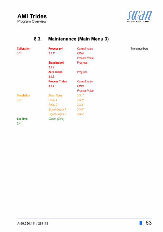
8.3. Maintenance (Main Menu 3)
Calibration Process pH Current Value * Menu numbers
3.1* 3.1.1* Offset
Process Value
Standard pH Progress
3.1.2
Zero Trides Progress
3.1.3
Process Trides Current Value
3.1.4 Offset
Process Value
Simulation Alarm Relay 3.3.1*
3.3* Relay 1 3.3.2*
Relay 2 3.3.3*
Signal Output 1 3.3.4*
Signal Output 2 3.3.5*
Set Time (Date), (Time)
3.4*
A-96.250.111 / 281113 63
AMI TridesProgram Overview
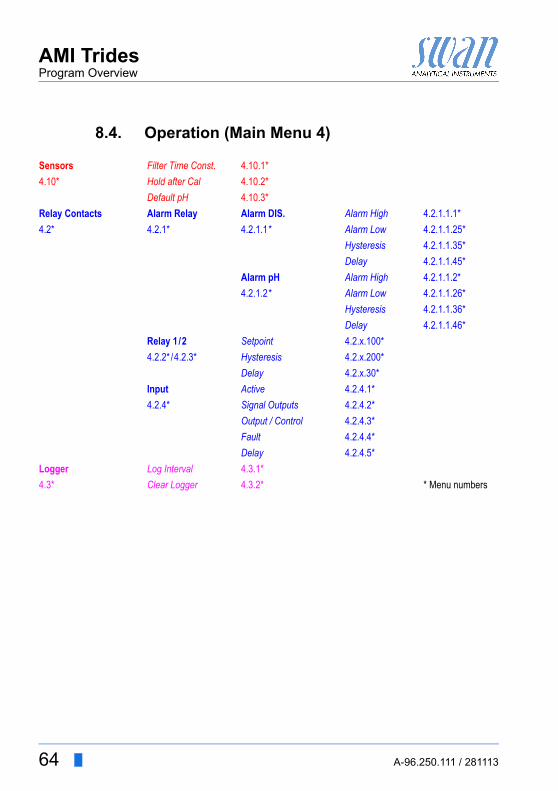
8.4. Operation (Main Menu 4)
Sensors Filter Time Const. 4.10.1*
4.10* Hold after Cal 4.10.2*
Default pH 4.10.3*
Relay Contacts Alarm Relay Alarm DIS. Alarm High 4.2.1.1.1*
4.2* 4.2.1* 4.2.1.1* Alarm Low 4.2.1.1.25*
Hysteresis 4.2.1.1.35*
Delay 4.2.1.1.45*
Alarm pH Alarm High 4.2.1.1.2*
4.2.1.2* Alarm Low 4.2.1.1.26*
Hysteresis 4.2.1.1.36*
Delay 4.2.1.1.46*
Relay 1/2 Setpoint 4.2.x.100*
4.2.2* /4.2.3* Hysteresis 4.2.x.200*
Delay 4.2.x.30*
Input Active 4.2.4.1*
4.2.4* Signal Outputs 4.2.4.2*
Output / Control 4.2.4.3*
Fault 4.2.4.4*
Delay 4.2.4.5*
Logger Log Interval 4.3.1*
4.3* Clear Logger 4.3.2* * Menu numbers
64 A-96.250.111 / 281113
AMI TridesProgram Overview
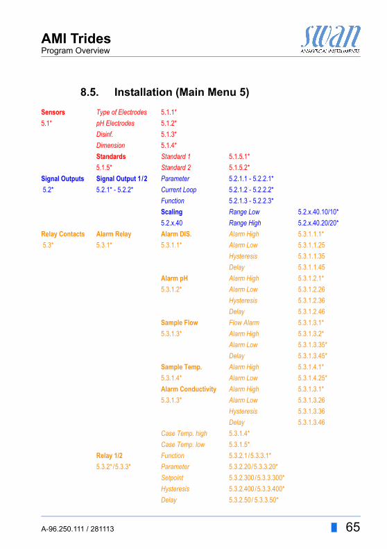
8.5. Installation (Main Menu 5)
Sensors Type of Electrodes 5.1.1*
5.1* pH Electrodes 5.1.2*
Disinf. 5.1.3*
Dimension 5.1.4*
Standards Standard 1 5.1.5.1*
5.1.5* Standard 2 5.1.5.2*
Signal Outputs Signal Output 1/2 Parameter 5.2.1.1 - 5.2.2.1*
5.2* 5.2.1* - 5.2.2* Current Loop 5.2.1.2 - 5.2.2.2*
Function 5.2.1.3 - 5.2.2.3*
Scaling Range Low 5.2.x.40.10/10*
5.2.x.40 Range High 5.2.x.40.20/20*
Relay Contacts Alarm Relay Alarm DIS. Alarm High 5.3.1.1.1*
5.3* 5.3.1* 5.3.1.1* Alarm Low 5.3.1.1.25
Hysteresis 5.3.1.1.35
Delay 5.3.1.1.45
Alarm pH Alarm High 5.3.1.2.1*
5.3.1.2* Alarm Low 5.3.1.2.26
Hysteresis 5.3.1.2.36
Delay 5.3.1.2.46
Sample Flow Flow Alarm 5.3.1.3.1*
5.3.1.3* Alarm High 5.3.1.3.2*
Alarm Low 5.3.1.3.35*
Delay 5.3.1.3.45*
Sample Temp. Alarm High 5.3.1.4.1*
5.3.1.4* Alarm Low 5.3.1.4.25*
Alarm Conductivity Alarm High 5.3.1.3.1*
5.3.1.3* Alarm Low 5.3.1.3.26
Hysteresis 5.3.1.3.36
Delay 5.3.1.3.46
Case Temp. high 5.3.1.4*
Case Temp. low 5.3.1.5*
Relay 1/2 Function 5.3.2.1/5.3.3.1*
5.3.2*/5.3.3* Parameter 5.3.2.20/5.3.3.20*
Setpoint 5.3.2.300/5.3.3.300*
Hysteresis 5.3.2.400/5.3.3.400*
Delay 5.3.2.50/ 5.3.3.50*
A-96.250.111 / 281113 65
AMI TridesProgram Overview
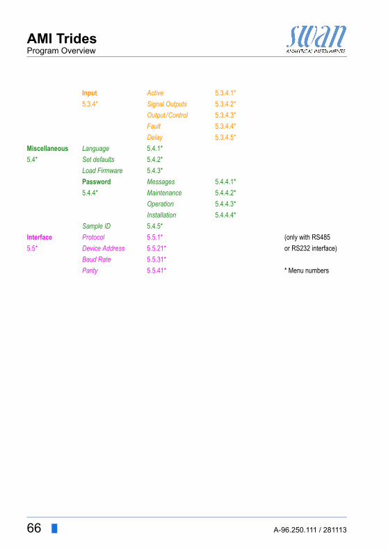
Input Active 5.3.4.1*
5.3.4* Signal Outputs 5.3.4.2*
Output /Control 5.3.4.3*
Fault 5.3.4.4*
Delay 5.3.4.5*
Miscellaneous Language 5.4.1*
5.4* Set defaults 5.4.2*
Load Firmware 5.4.3*
Password Messages 5.4.4.1*
5.4.4* Maintenance 5.4.4.2*
Operation 5.4.4.3*
Installation 5.4.4.4*
Sample ID 5.4.5*
Interface Protocol 5.5.1* (only with RS485
5.5* Device Address 5.5.21* or RS232 interface)
Baud Rate 5.5.31*
Parity 5.5.41* * Menu numbers
66 A-96.250.111 / 281113
AMI TridesProgram List and Explanations
9. Program List and Explanations
1 Messages
1.1 Pending Errors1.1.5 Provides the list of active errors with their status (active, acknowl-
edged). If an active error is acknowledged, the alarm relay opens again. Cleared errors are moved to the Message list.
1.2 Message List1.2.1 Shows the error history: Error code, date / time of issue and status
(active, acknowledged, cleared). 65 errors are memorized. Then the oldest error is cleared to save the newest error (circular buffer).
2 DiagnosticsIn diagnostics mode, the values can only be viewed, not modified.
2.1 IdentificationDesig.: Designation of the instrument.Version: Firmware of instrument (e.g. V5.31-1012)
2.1.3 Factory Test: Test date of the Instrument and Motherboard
2.1.4 Operating Time: Years / Days / Hours / Minutes / Seconds
2.2 Sensors
2.2.1 Trides Sensor:Current value: Shows the current disinfectant measuring value in ppmRaw value 1: Shows the actual sensor current in µA, withoutcompensation of temperature (and pH).Raw value 2: Shows the actual sensor current in µA, withcompensation of temperature (and pH).Ref. voltage: Shows the actual voltage of counter electrode (CE) in mV. Values for most applications are within 800 - 1300 mV.
2.2.1.5 Cal. History: Review the diagnostic values of the last calibrations. Number, Date, Time, Offset [µA], Slope [µA]
A-96.250.111 / 281113 67
AMI TridesProgram List and Explanations
2.2.2 Electrode (only available if option pH/Redox is installed):Current value: Shows the current pH value.Raw value: Shows the current voltage of the pH electrode in mV.
2.2.3 Miscellaneous:
2.2.3.1 Case Temp: Shows the current temperature in [°C] inside the trans-mitter.
2.3 Sample
2.3.1 Sample ID: Shows the identification assigned to a sample. This identification is defined by the user to identify the location of the sample.Temperature: Shows the current temperature in °C and NT5K in Ohm.Sample Flow: Shows the current sample flow in rotations per min-ute (rpm)
2.4 I/O StateShows current status of all in- and outputs.
2.4.1/2.4.2
2.5 InterfaceOnly available if optional interface is installed.Review programmed communication settings.
Alarm Relay: Open or closed.
Relay 1 and 2: Open or closed.
Input: Open or closed.
Signal Output 1 and 2: Actual current in mA
Signal Output 3: Actual current in mA (if option is installed)
68 A-96.250.111 / 281113
AMI TridesProgram List and Explanations
3 Maintenance
3.1 Calibration3.1.1 Process pH: Only available if option pH is installed.
The function Process pH is a calibration based on a comparative measurement of the current electrode with a calibrated compara-tive electrode. See Process pH, p. 49.
3.1.2 Standard pH: Only available if option pH is installed.Performs a standard calibration (2-point calibration) with two stan-dard solution of different pH. See Standard pH, p. 50.
3.1.3 Zero Trides: Provides a zero adjustment of the Trides sensor. See Zero Trides, p. 51.
3.1.4 Process Trides: The function Process Trides is a calibration based on a comparative measurement of the Trides sensor with a photo-metric measurement (eg. Swan Chematest 25). See Process Trides, p. 51
3.3 SimulationTo simulate a value or a relay state, select the alarm relay, relay 1 and 2 signal output 1 and 2
with the [ ] or [ ] key.Press the [Enter] key.Change the value or state of the selected item with the [ ] or [ ] key. Press the [Enter] key.
The value is simulated by the relay/signal output.
At the absence of any key activities, the instrument will switch back to normal mode after 20 min. If you quit the menu, all simulated val-ues will be reset.
3.4 Set TimeAdjust date and time.
Alarm Relay: Open or closed.
Relay 1 and 2: Open or closed.
Signal Output 1 and 2: Actual current in mA
Signal Output 3: Actual current in mA (if option is installed)
A-96.250.111 / 281113 69
AMI TridesProgram List and Explanations
4 Operation
4.10 Sensors4.10.1 Filter Time Constant: Used to damp noisy signals. The higher the
filter time constant, the slower the system reacts to changes of the measured value.Range: 5–300 Sec
4.10.2 Hold after Cal.: Delay permitting the instrument to stabilize again af-ter calibration. During calibration plus hold-time, the signal outputs are frozen (held on last valid value), alarm values, limits are not ac-tive.Range: 0–6‘000 Sec
4.10.3 Default pH: Used for pH compensation of free chlorine measure-ment if no pH electrode is connected and programmed. See chap-ter 2 for more details. For ozone, chlorine-dioxide, bromine, iodide, no pH compensation is necessary. Range: 0.00 - 14.00 pH
4.2 Relay ContactsSee Relay Contacts, p. 28
4.3 LoggerThe instrument is equipped with an internal logger. The data can be downloaded to a PC by SWAN Terminal if option “SWAN Terminal interface” is installed or via USB stick if option “USB interface” is in-stalled.The logger can save approx. 1500 data records. The Records con-sists of: Date, time, alarms of all available measuring values.Range: 1 Second to 1 hour
4.4.1 Log Interval: Select a convenient log interval. Consult the table be-low to estimate the max logging time. When the logging buffer is full, the oldest data record is erased to make room for the newest one (circular buffer).
4.4.2 Clear Logger: If confirmed with yes, the complete logger data is de-leted. A new data series is started.
Interval 1 s 5 s 1 min 5 min 10 min 30 min 1 h
Time 25 min 2 h 25 h 5 d 10 d 31 d 62 d
70 A-96.250.111 / 281113
AMI TridesProgram List and Explanations
5 Installation
5.1 Sensors5.1.1 Type of Electrode: If pH or Redox option is installed set the type of
electrode according.
5.1.2 pH Electrode: If pH option is installed, set “pH Electrode” to <with>.
5.1.3 Disinf.: Set the disinfectant you want measure: Free chlorine Hypochlorous acid Ozone Chlorine dioxide Bromine Iodine Free + HoCl
5.1.4 Dimension: Set the dimension of the measured value either to ppm or mg/l.
5.1.5 Standards: If you want to use standard solutions different from the recommended SWAN standard solutions, enter the value of:
5.1.5.1 Standard 1:Range: pH 1 to pH 13
5.1.5.2 Standard 2:Range: pH 1 to pH 13
A-96.250.111 / 281113 71
AMI TridesProgram List and Explanations
5.2 Signal Outputs
Note: The navigation in the menu <Signal Output 1> and <Signal Output 2> is equal. For reason of simplicity only the menu numbers of Signal Output 1 are used in the following.
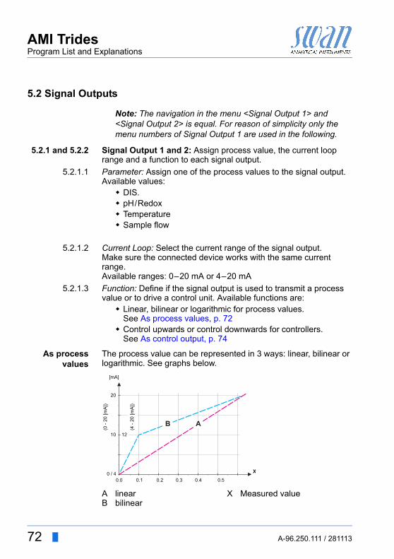
5.2.1 and 5.2.2 Signal Output 1 and 2: Assign process value, the current loop range and a function to each signal output.
5.2.1.1 Parameter: Assign one of the process values to the signal output.Available values: DIS. pH/Redox Temperature Sample flow
5.2.1.2 Current Loop: Select the current range of the signal output.Make sure the connected device works with the same current range.Available ranges: 0–20 mA or 4–20 mA
5.2.1.3 Function: Define if the signal output is used to transmit a process value or to drive a control unit. Available functions are: Linear, bilinear or logarithmic for process values.
See As process values, p. 72 Control upwards or control downwards for controllers.
See As control output, p. 74
As processvalues
The process value can be represented in 3 ways: linear, bilinear or logarithmic. See graphs below.
AB
linearbilinear
X Measured value
20
0.0 0.1 0.2 0.3 0.4 0.5
10 12
(0 -
20 [m
A])
0 / 4
(4 -
20 [m
A])
[mA]
X
AB
72 A-96.250.111 / 281113
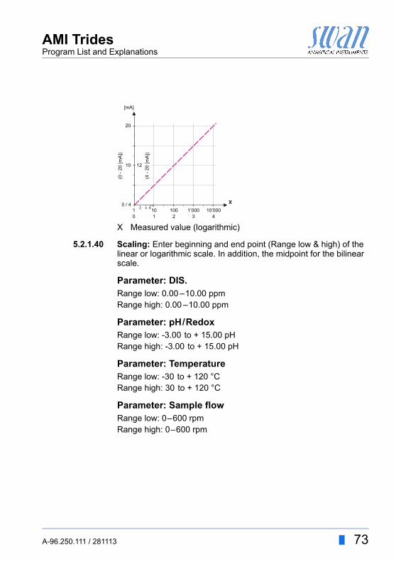
AMI TridesProgram List and Explanations
5.2.1.40 Scaling: Enter beginning and end point (Range low & high) of the linear or logarithmic scale. In addition, the midpoint for the bilinear scale.
Parameter: DIS.Range low: 0.00 –10.00 ppmRange high: 0.00 –10.00 ppm
Parameter: pH/RedoxRange low: -3.00 to + 15.00 pHRange high: -3.00 to + 15.00 pH
Parameter: TemperatureRange low: -30 to + 120 °CRange high: 30 to + 120 °C
Parameter: Sample flowRange low: 0–600 rpmRange high: 0–600 rpm
X Measured value (logarithmic)
20
10 1 2 3 4
10 100 1’000 10’000
10 12
(0 -
20 [m
A])
0 / 442 6
(4 -
20 [m
A])
[mA]
X
A-96.250.111 / 281113 73
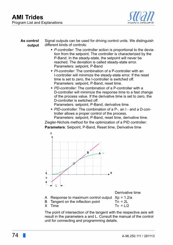
AMI TridesProgram List and Explanations
As controloutput
Signal outputs can be used for driving control units. We distinguish different kinds of controls: P-controller: The controller action is proportional to the devia-
tion from the setpoint. The controller is characterized by the P-Band. In the steady-state, the setpoint will never be reached. The deviation is called steady-state error.Parameters: setpoint, P-Band
PI-controller: The combination of a P-controller with anI-controller will minimize the steady-state error. If the reset time is set to zero, the I-controller is switched off.Parameters: setpoint, P-Band, reset time.
PD-controller: The combination of a P-controller with a D-controller will minimize the response time to a fast change of the process value. If the derivative time is set to zero, the D-controller is switched off.Parameters: setpoint, P-Band, derivative time.
PID-controller: The combination of a P-, an I - and a D-con-troller allows a proper control of the process.Parameters: setpoint, P-Band, reset time, derivative time.
Ziegler-Nichols method for the optimization of a PID controller:Parameters: Setpoint, P-Band, Reset time, Derivative time
The point of intersection of the tangent with the respective axis will result in the parameters a and L. Consult the manual of the control unit for connecting and programming details.
Derrivative timeABX
Response to maximum control outputTangent on the inflection pointTime
XpTnTv
= 1.2/a= 2L= L/2
X
Y
B A
L
a
74 A-96.250.111 / 281113
AMI TridesProgram List and Explanations
Control upwards or downwards.Setpoint: User defined precess value for the selected parameter.P-Band: Range below (upwards control) or above (downwards con-trol) the set-point, within which the dosing intensity is reduced from 100% to 0% to reach the set-point without overshooting.
5.2.1.43 Control Parameters: if Parameter = DIS.5.2.1.43.10 Setopint:
Range: 0.00 –10.00 ppm5.2.1.43.20 P-Band:
Range: 0.00 –10.00 ppm
5.2.1.43 Control Parameters: if Parameter = pH/Redox5.2.1.43.11 Setopint:
Range: -3.00 to + 15.00 pH5.2.1.43.21 P-Band:
Range: 0.00 –2.00 pH
5.2.1.43 Control Parameters: if Parameter = Temperature5.2.1.43.12 Setopint:
Range: -30 to + 120 °C5.2.1.43.22 P-Band:
Range: 0.00 –100 °C
5.2.1.43 Control Parameters: if Parameter = Sample flow5.2.1.43.13 Setopint:
Range: 0–600 rpm5.2.1.43.23 P-Band:
Range: 0–600 rpm
Reset time: The reset time is the time till the step response of a sin-gle I-controller will reach the same value as it will be suddenly reached by a P-controller.Range: 0–9’000 secDerivative time: The derivative time is the time till the ramp re-sponse of a single P-controller will reach the same value as it will be suddenly reached by a D-controller.Range: 0–9’000 secControl timeout: If a controller action (dosing intensity) is constantly over 90% during a defined period of time and the process value does not come closer to the setpoint, the dosing process will be stopped for safety reasons.Range: 0–720 min
A-96.250.111 / 281113 75
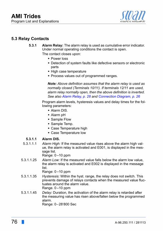
AMI TridesProgram List and Explanations
5.3 Relay Contacts
5.3.1 Alarm Relay: The alarm relay is used as cumulative error indicator. Under normal operating conditions the contact is open.The contact closes upon: Power loss Detection of system faults like defective sensors or electronic
parts High case temperature Process values out of programmed ranges.
Note: Above definition assumes that the alarm relay is used as normally closed (Terminals 10/11). If terminals 12/11 are used, alarm relay normally open, then the above definition is inverted. See also Alarm Relay, p. 28 and Connection Diagram, p. 26
Program alarm levels, hysteresis values and delay times for the fol-lowing parameters: Alarm DIS. Alarm pH Sample Flow Sample Temp. Case Temperature high Case Temperature low
5.3.1.1 Alarm DIS.5.3.1.1.1 Alarm High: If the measured value rises above the alarm high val-
ue, the alarm relay is activated and E001, is displayed in the mes-sage list. Range: 0 –10 ppm
5.3.1.1.25 Alarm Low: If the measured value falls below the alarm low value, the alarm relay is activated and E002 is displayed in the message list.Range: 0 –10 ppm
5.3.1.1.35 Hysteresis: Within the hyst. range, the relay does not switch. This prevents damage of relays contacts when the measured value fluc-tuates around the alarm value.Range. 0 –10 ppm
5.3.1.1.45 Delay: Duration, the activation of the alarm relay is retarded after the measuring value has risen above/fallen below the programmed alarm.Range: 0–28‘800 Sec
76 A-96.250.111 / 281113
AMI TridesProgram List and Explanations
5.3.1.2 Alarm pH5.3.1.2.1 Alarm High: If the measured value rises above the alarm high val-
ue, the alarm relay is activated and E003, is displayed in the mes-sage list. Range: -3.00 to + 15.00 pH
5.3.1.2.25 Alarm Low: If the measured value falls below the alarm low value, the alarm relay is activated and E004 is displayed in the message list.Range: -3.00 to + 15.00 pH
5.3.1.2.35 Hysteresis: Within the hyst. range, the relay does not switch. This prevents damage of relays contacts when the measured value fluc-tuates around the alarm value.Range. 0 –2 pH
5.3.1.2.45 Delay: Duration, the activation of the alarm relay is retarded after the measuring value has risen above/fallen below the programmed alarm.Range: 0–28‘800 Sec
5.3.1.3 Sample Flow: Define at which sample flow an alarm should be is-sued.
5.3.1.3.1 Flow Alarm: Program if the alarm relay should be activated if there is a flow alarm. Choose between yes or no. The flow alarm will always be indicated in the display, pending error list, saved in the message list and the logger.Available values: Yes or no
Note: Sufficient flow is essential for a correct measurement.We recommend to program yes.
5.3.1.3.2 Alarm High: If the measuring values rises above the programmed value E009 will be issued.Range: 400–9000 rpm
5.3.1.3.35 Alarm Low: If the measuring values falls below the programmed value E010 will be issued.Range: 200–350 rpm
5.3.1.3.45 Delay: Duration, the activation of the alarm relay is retarded after the measuring value has risen above/fallen below the programmed alarm.Range: 0–28‘800 Sec
A-96.250.111 / 281113 77
AMI TridesProgram List and Explanations
5.3.1.4 Sample Temp
5.3.1.4.1 Alarm High: If the measured value rises above the alarm high val-ue, the alarm relay is activated and E003, is displayed in the mes-sage list. Range: 30–70 °C
5.3.1.4.25 Alarm Low: If the measured value falls below the alarm low value, the alarm relay is activated and E004 is displayed in the message list.Range: 0–20 °C
5.3.1.5 Case Temp. high: Set the alarm high value for temperature of electronics housing. If the value rises above the programmed value E013 is issued.Range: 30–75 °C
5.3.1.6 Case Temp. low: Set the alarm low value for temperature of elec-tronics housing. If the value falls below the programmed value E014 is issued.Range: -10–20 °C
5.3.2 and 5.3.3 Relay 1 and 2: The contacts can be set as normally open or nor-mally closed with a jumper, see Relay 1 and 2, p. 29. The function of relay contacts 1 or 2 are defined by the user.
Note: The navigation in the menu <Relay 1> and <Relay 2> is equal. For reason of simplicity only the menu numbers of Relay 1 are used in the following.
1 First select the functions as:- Limit upper/lower, - Control upwards/downwards, - Timer- Fieldbus,
2 Then enter the necessary data depending on the selected func-tion. The same values may also be entered in menu 4.2 Relay Contacts, p. 70
78 A-96.250.111 / 281113

AMI TridesProgram List and Explanations
When the relays are used as upper or lower limit switches, program the following:
5.3.2.20 Parameter: choose one of the following process values DIS. pH/Redox Temperature Sample Flow
5.3.2.300 Setpoint: If the measured value rises above respectively falls below the set-point, the relay is activated.
5.3.2.400 Hysteresis: within the hysteresis range, the relay does not switch. This prevents damage of relay contacts when the measured value fluctuates around the alarm value.
5.3.2.50 Delay: Duration, the activation of the alarm relay is retarded after the measuring value has risen above/fallen below the programmed alarm.Range. 0–600 Sec
5.3.2.1 Function = Limit upper/lower:
Parameter Range
DIS 0.00–10 ppm
pH/Redox -3.00 to +15.00 pH
Temperature -30 °C to +120 °C
Sample Flow 0–600 rpm
Parameter Range
DIS 0.00–10 ppm
pH/Redox 0–2 pH
Temperature 0–120 °C
Sample Flow 0–600 rpm
A-96.250.111 / 281113 79
AMI TridesProgram List and Explanations
The relays may be used to drive control units such as solenoid valves, membrane dosing pumps or motor valves. When driving a motor valve both relays are needed, relay 1 to open and relay 2 to close the valve.
5.3.2.22 Parameter: choose one of the following process values DIS. pH/Redox Temperature Sample Flow
5.3.2.32 Settings Choose the respective actuator: Time proportional Frequency, Motor valve
Examples of metering devices that are driven time proportional are solenoid valves, peristaltic pumps.Dosing is controlled by the operating time.
5.3.2.32.20 Cycle time: duration of one control cycle (on/off change).Range: 0–600 sec.
5.3.2.32.30 Response time: Minimal time the metering device needs to react. Range: 0–240 sec.
5.3.2.32.4 Control Parameters: Range for each Parameter same as 5.2.1.43, p. 75
Examples of metering devices that are pulse frequency driven are the classic membrane pumps with a potential free triggering input. Dosing is controlled by the repetition speed of dosing shots.
5.3.2.32.21 Pulse frequency: Max. pulses per minute the device is able to re-spond to. Range: 20–300/min.
5.3.2.1 Function = Control upwards/downwards::
Actuator = Time proportional
Actuator = Frequency
80 A-96.250.111 / 281113
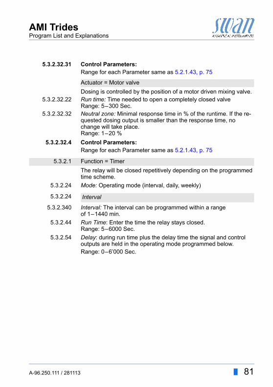
AMI TridesProgram List and Explanations
5.3.2.32.31 Control Parameters:Range for each Parameter same as 5.2.1.43, p. 75
Dosing is controlled by the position of a motor driven mixing valve.5.3.2.32.22 Run time: Time needed to open a completely closed valve
Range: 5–300 Sec.5.3.2.32.32 Neutral zone: Minimal response time in % of the runtime. If the re-
quested dosing output is smaller than the response time, no change will take place.Range: 1–20 %
5.3.2.32.4 Control Parameters:Range for each Parameter same as 5.2.1.43, p. 75
The relay will be closed repetitively depending on the programmed time scheme.
5.3.2.24 Mode: Operating mode (interval, daily, weekly)
5.3.2.340 Interval: The interval can be programmed within a rangeof 1–1440 min.
5.3.2.44 Run Time: Enter the time the relay stays closed.Range: 5–6000 Sec.
5.3.2.54 Delay: during run time plus the delay time the signal and control outputs are held in the operating mode programmed below.Range: 0–6’000 Sec.
Actuator = Motor valve
5.3.2.1 Function = Timer
5.3.2.24 Interval
A-96.250.111 / 281113 81
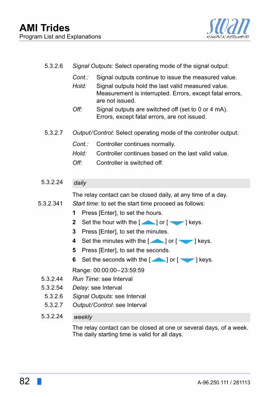
AMI TridesProgram List and Explanations
5.3.2.6 Signal Outputs: Select operating mode of the signal output:
5.3.2.7 Output/Control: Select operating mode of the controller output:
The relay contact can be closed daily, at any time of a day.
5.3.2.341 Start time: to set the start time proceed as follows:
1 Press [Enter], to set the hours.
2 Set the hour with the [ ] or [ ] keys.
3 Press [Enter], to set the minutes.
4 Set the minutes with the [ ] or [ ] keys.
5 Press [Enter], to set the seconds.
6 Set the seconds with the [ ] or [ ] keys.
Range: 00:00:00–23:59:59
5.3.2.44 Run Time: see Interval
5.3.2.54 Delay: see Interval
5.3.2.6 Signal Outputs: see Interval
5.3.2.7 Output/Control: see Interval
The relay contact can be closed at one or several days, of a week. The daily starting time is valid for all days.
Cont.: Signal outputs continue to issue the measured value.
Hold: Signal outputs hold the last valid measured value.Measurement is interrupted. Errors, except fatal errors, are not issued.
Off: Signal outputs are switched off (set to 0 or 4 mA).Errors, except fatal errors, are not issued.
Cont.: Controller continues normally.
Hold: Controller continues based on the last valid value.
Off: Controller is switched off.
5.3.2.24 daily
5.3.2.24 weekly
82 A-96.250.111 / 281113
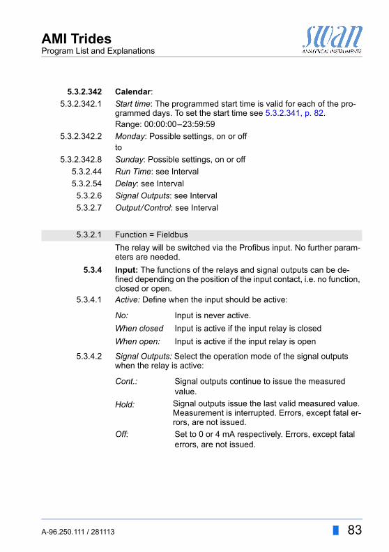
AMI TridesProgram List and Explanations
5.3.2.342 Calendar:
5.3.2.342.1 Start time: The programmed start time is valid for each of the pro-grammed days. To set the start time see 5.3.2.341, p. 82.Range: 00:00:00–23:59:59
5.3.2.342.2 Monday: Possible settings, on or offto
5.3.2.342.8 Sunday: Possible settings, on or off
5.3.2.44 Run Time: see Interval
5.3.2.54 Delay: see Interval
5.3.2.6 Signal Outputs: see Interval
5.3.2.7 Output/Control: see Interval
The relay will be switched via the Profibus input. No further param-eters are needed.
5.3.4 Input: The functions of the relays and signal outputs can be de-fined depending on the position of the input contact, i.e. no function, closed or open.
5.3.4.1 Active: Define when the input should be active:
5.3.4.2 Signal Outputs: Select the operation mode of the signal outputs when the relay is active:
5.3.2.1 Function = Fieldbus
No: Input is never active.
When closed Input is active if the input relay is closed
When open: Input is active if the input relay is open
Cont.: Signal outputs continue to issue the measured value.
Hold: Signal outputs issue the last valid measured value.Measurement is interrupted. Errors, except fatal er-rors, are not issued.
Off: Set to 0 or 4 mA respectively. Errors, except fatal errors, are not issued.
A-96.250.111 / 281113 83
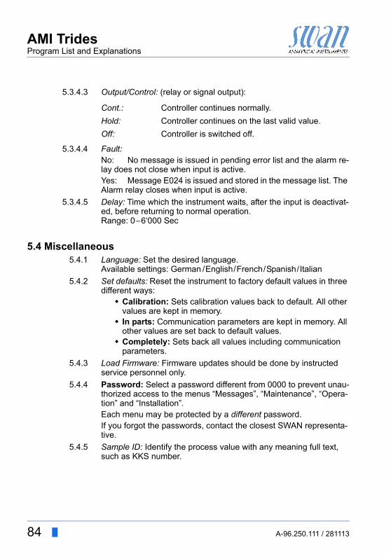
AMI TridesProgram List and Explanations
5.3.4.3 Output/Control: (relay or signal output):
5.3.4.4 Fault: No: No message is issued in pending error list and the alarm re-lay does not close when input is active.Yes: Message E024 is issued and stored in the message list. The Alarm relay closes when input is active.
5.3.4.5 Delay: Time which the instrument waits, after the input is deactivat-ed, before returning to normal operation.Range: 0–6‘000 Sec
5.4 Miscellaneous5.4.1 Language: Set the desired language.
Available settings: German /English/French/Spanish/Italian
5.4.2 Set defaults: Reset the instrument to factory default values in three different ways: Calibration: Sets calibration values back to default. All other
values are kept in memory. In parts: Communication parameters are kept in memory. All
other values are set back to default values. Completely: Sets back all values including communication
parameters.
5.4.3 Load Firmware: Firmware updates should be done by instructed service personnel only.
5.4.4 Password: Select a password different from 0000 to prevent unau-thorized access to the menus “Messages”, “Maintenance”, “Opera-tion” and “Installation”.Each menu may be protected by a different password.If you forgot the passwords, contact the closest SWAN representa-tive.
5.4.5 Sample ID: Identify the process value with any meaning full text, such as KKS number.
Cont.: Controller continues normally.
Hold: Controller continues on the last valid value.
Off: Controller is switched off.
84 A-96.250.111 / 281113
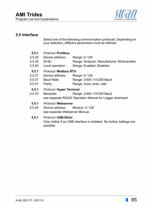
AMI TridesProgram List and Explanations
5.5 InterfaceSelect one of the following communication protocols. Depending on your selection, different parameters must be defined.
5.5.1 Protocol: Profibus5.5.20 Device address: Range: 0–1265.5.30 ID-Nr.: Range: Analyzer; Manufacturer; Multivariable5.5.40 Local operation: Range: Enabled, Disabled
5.5.1 Protocol: Modbus RTU5.5.21 Device address: Range: 0–1265.5.31 Baud Rate: Range: 2 400–115 200 Baud5.5.41 Parity: Range: none, even, odd
5.5.1 Protocol: Hyper Terminal5.5.23 Baudrate: Range: 2 400–115 200 Baud
see separate RS232 Operation Manual for Logger download.
5.5.1 Protocol: Webserver:5.5.24 Device address: Bereich: 0–126
see separate Webserver Manual.
5.5.1 Protocol: USB-Stick:Only visible if an USB interface is installed. No further settings are possible.
A-96.250.111 / 281113 85

86 A-96.250.111 / 281113
AMI TridesMaterial Safety Data sheets
10. Material Safety Data sheets
10.1. Reagents
Calibration Solution pH 4 Calibration Solution pH 7 Calibration Solution pH 9
DownloadMSDS
The current Material Safety Data Sheets (MSDS) for the above list-ed Reagents are available for downloading at www.swan.ch.
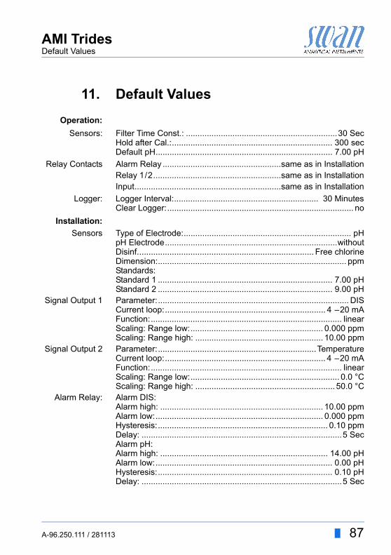
AMI TridesDefault Values
11. Default Values
Operation:
Sensors: Filter Time Const.: .................................................................30 SecHold after Cal.:..................................................................... 300 secDefault pH............................................................................ 7.00 pH
Relay Contacts Alarm Relay ...................................................same as in InstallationRelay 1/2.......................................................same as in InstallationInput...............................................................same as in Installation
Logger: Logger Interval:.............................................................. 30 MinutesClear Logger:................................................................................ no
Installation:
Sensors Type of Electrode:........................................................................ pHpH Electrode..........................................................................withoutDisinf............................................................................ Free chlorineDimension:................................................................................. ppmStandards:Standard 1 ........................................................................... 7.00 pHStandard 2 ........................................................................... 9.00 pH
Signal Output 1 Parameter:.................................................................................. DISCurrent loop:..................................................................... 4 –20 mAFunction:.................................................................................. linearScaling: Range low:......................................................... 0.000 ppmScaling: Range high: ....................................................... 10.00 ppm
Signal Output 2 Parameter:....................................................................TemperatureCurrent loop:..................................................................... 4 –20 mAFunction:.................................................................................. linearScaling: Range low:................................................................ 0.0 °CScaling: Range high: ............................................................ 50.0 °C
Alarm Relay: Alarm DIS:Alarm high: ...................................................................... 10.00 ppmAlarm low:........................................................................ 0.000 ppmHysteresis:......................................................................... 0.10 ppmDelay: ......................................................................................5 SecAlarm pH:Alarm high: ........................................................................ 14.00 pHAlarm low:............................................................................ 0.00 pHHysteresis:........................................................................... 0.10 pHDelay: ......................................................................................5 Sec
A-96.250.111 / 281113 87
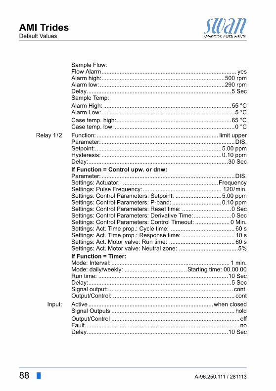
AMI TridesDefault Values
Sample Flow:Flow Alarm.................................................................................. yesAlarm high:...........................................................................500 rpmAlarm low: ............................................................................290 rpmDelay........................................................................................5 SecSample Temp:Alarm High: ..............................................................................55 °CAlarm Low:.................................................................................5 °CCase temp. high:......................................................................65 °CCase temp. low: .........................................................................0 °C
Relay 1/2 Function: .......................................................................... limit upperParameter: .................................................................................DIS.Setpoint:.............................................................................5.00 ppmHysteresis: .........................................................................0.10 ppmDelay:.....................................................................................30 SecIf Function = Control upw. or dnw:Parameter: .................................................................................DIS.Settings: Actuator: ..........................................................FrequencySettings: Pulse Frequency:................................................ 120/min.Settings: Control Parameters: Setpoint: ............................5.00 ppmSettings: Control Parameters: P-band: ..............................0.10 ppmSettings: Control Parameters: Reset time: ..............................0 SecSettings: Control Parameters: Derivative Time:.......................0 SecSettings: Control Parameters: Control Timeout: ..................... 0 Min.Settings: Act. Time prop.: Cycle time: ....................................... 60 sSettings: Act. Time prop.: Response time: ................................ 10 sSettings: Act. Motor valve: Run time: ........................................ 60 sSettings: Act. Motor valve: Neutral zone: ....................................5%If Function = Timer:Mode: Interval: ........................................................................ 1 min.Mode: daily/weekly: ......................................Starting time: 00.00.00Run time: ...............................................................................10 SecDelay:.......................................................................................5 SecSignal output:............................................................................ cont.Output/Control: .......................................................................... cont
Input: Active ............................................................................when closedSignal Outputs ........................................................................... holdOutput/Control ..............................................................................offFault..............................................................................................noDelay......................................................................................10 Sec
88 A-96.250.111 / 281113
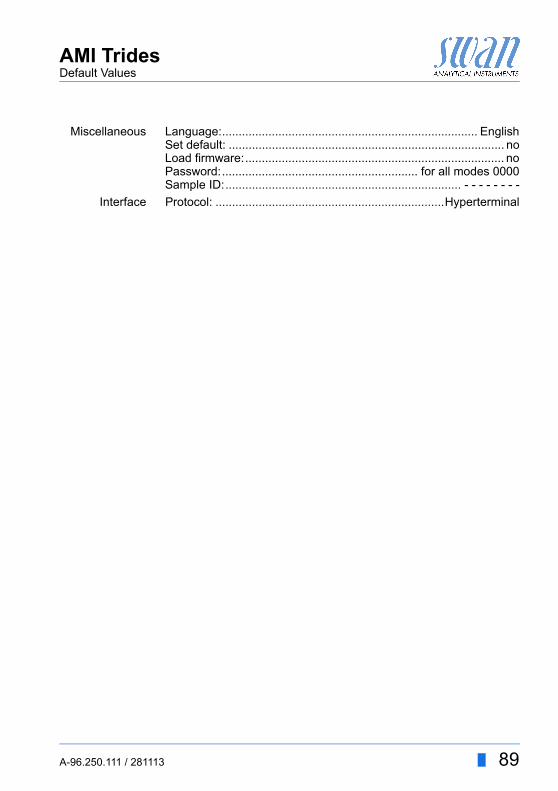
AMI TridesDefault Values
Miscellaneous Language:............................................................................. EnglishSet default: ................................................................................... noLoad firmware:.............................................................................. noPassword:........................................................... for all modes 0000Sample ID:....................................................................... - - - - - - - -
Interface Protocol: .....................................................................Hyperterminal
A-96.250.111 / 281113 89
AMI TridesIndex
12. Index
AAlarm Relay . . . . . . . 10, 28Application . . . . . . . . . . . 9Application Range . . . . . . . 9
CCable thicknesses . . . . . . 24Calendar. . . . . . . . . . . . 83Changing values . . . . . . . 39Checklist. . . . . . . . . . . . 17Cleaning
Flow Cell . . . . . . . . . 47pH Electrode. . . . . . . 46Reference Electrode . . 45Trides protective filter . 42Trides sensor . . . . . . 43
Clear Logger . . . . . . . . . 70Connect
Sample inlet . . . . . . . 18Waste. . . . . . . . . . . 18
Control timeout . . . . . . . . 75
DDefault pH. . . . . . . . . . . 70Default Values . . . . . . . . 87Derivative time . . . . . . . . 75
EElectrodes, Installation of . . 32Error List. . . . . . . . . . . . 55
FFilter Time Constant . . . . . 70Flow . . . . . . . . . . . . . . 47Fluidics . . . . . . . . . . . . 13free chlorine. . . . . . . . . . 11
GGrab sample . . . . . . . . . 12
HHold after Cal . . . . . . . . . 70Hypochlorous acid . . . . . . 12
IInput . . . . . . . . . . . 10, 28Instrument Overview. . . . . 16Interface . . . . . . . . . 10, 32Interface RS232 . . . . . . . 32Interface RS485 . . . . . . . 32
LLog Interval . . . . . . . . . . 70
MMeasuring principle . . . . . 11Mounting
Instrument panel . . . . 18Mounting requirements . . . 18
OOn site requirements . . . . 17On-line operation. . . . . . . 12
PP-Band . . . . . . . . . . . . 75Power Supply . . . . . . . . . 27
RRelays . . . . . . . . . . . . . . 9Requirements, on-site . . . . 14Reset time. . . . . . . . . . . 75
90 A-96.250.111 / 281113
AMI TridesIndex
SSafety Features . . . . . . . 10Sample ID . . . . . . . . . . 68Sample requirements . . . . 14Set Time . . . . . . . . . . . 69Setpoint
. . . . . . . . . . . . . . 75Setup . . . . . . . . . . . . . 34Signal Outputs . . . . . . . 9, 31Simulation . . . . . . . . . . 69Software . . . . . . . . . . . 38Standard pH Calibration . . 50System, Description of . . . . 9
TTechnical Data. . . . . . . . 16Terminals . . . . 26, 28–29, 32Type of Electrode . . . . . . 71
UUSB Interface . . . . . . . . 33
WWire . . . . . . . . . . . . . . 24
A-96.250.111 / 281113 91
AMI TridesNotes
13. Notes
92 A-96.250.111 / 281113

AMI TridesNotes
A-96.250.111 / 281113 93

94 A-96.250.111 / 281113
AMI Trides
SWANis represented worldwide by subsidiary companies and distributors.
cooperates with independent representatives all over the world.
SWAN Products
Analytical Instruments for:
High Purity Water
Feedwater, Steam and Condensate
Potable Water
Pool and Sanitary Water
Cooling Water
Waster Water and Effluents
Made in Switzerland