MenAMI Hydrazine 03 - SWAN
84
AMI Hydrazine Version 6.20 and higher A-96.250.501 / 020720 Operator’s Manual
Transcript of MenAMI Hydrazine 03 - SWAN

AMI HydrazineVersion 6.20 and higher
A-96.250.501 / 020720
Ope
rato
r’s M
anua
l

© 2020, SWAN ANALYTISCHE INSTRUMENTE AG, Switzerland, all rights reserved
subject to change without notice
Customer SupportSWAN and its representatives maintain a fully trained staff of technical specialists around the world. For any technical question, contact your nearest SWAN representative, or the manufacturer:SWAN ANALYTISCHE INSTRUMENTE AGStudbachstrasse 138340 HinwilSwitzerlandInternet: www.swan.chE-mail: [email protected]
Document Status
Title: AMI Hydrazine Operator’s Manual
ID: A-96.250.501
Revision Issue
00 June 2007 First Edition
01 April 2015 Update to Rev. 5.40, mainboard V2.4
02 July 2017 Update to Rev. 6.10, mainboard V2.5
03 July 2020 Mainboard V2.6

AMI Hydrazine
A-96.250.501 / 020720 1
Table of Content
1. Safety Instructions . . . . . . . . . . . . . . . . . . . . . . . . . . . . . . . . . . . 31.1. Warning Notices . . . . . . . . . . . . . . . . . . . . . . . . . . . . . . . . . . . . . . 41.2. General Safety Regulations . . . . . . . . . . . . . . . . . . . . . . . . . . . . . 61.3. Restrictions for use. . . . . . . . . . . . . . . . . . . . . . . . . . . . . . . . . . . . 7
2. Product Description . . . . . . . . . . . . . . . . . . . . . . . . . . . . . . . . . . 82.1. Description of the System. . . . . . . . . . . . . . . . . . . . . . . . . . . . . . . 82.2. Instrument Specification . . . . . . . . . . . . . . . . . . . . . . . . . . . . . . . . 112.3. Instrument Overview. . . . . . . . . . . . . . . . . . . . . . . . . . . . . . . . . . . 13
3. Installation. . . . . . . . . . . . . . . . . . . . . . . . . . . . . . . . . . . . . . . . . . 143.1. Installation Checklist Monitors . . . . . . . . . . . . . . . . . . . . . . . . . . . 143.2. Mounting of Instrument Panel. . . . . . . . . . . . . . . . . . . . . . . . . . . . 153.3. Connecting Sample and Waste . . . . . . . . . . . . . . . . . . . . . . . . . . 153.4. Install the Reference Electrode . . . . . . . . . . . . . . . . . . . . . . . . . . 163.5. Install the Temperature Sensor . . . . . . . . . . . . . . . . . . . . . . . . . . 173.6. Electrical Connections . . . . . . . . . . . . . . . . . . . . . . . . . . . . . . . . . 183.6.1 Connection Diagram . . . . . . . . . . . . . . . . . . . . . . . . . . . . . . . . . 203.6.2 Power Supply . . . . . . . . . . . . . . . . . . . . . . . . . . . . . . . . . . . . . . 213.7. Relay Contacts . . . . . . . . . . . . . . . . . . . . . . . . . . . . . . . . . . . . . . . 223.7.1 Input . . . . . . . . . . . . . . . . . . . . . . . . . . . . . . . . . . . . . . . . . . . . . 223.7.2 Alarm Relay. . . . . . . . . . . . . . . . . . . . . . . . . . . . . . . . . . . . . . . . 223.7.3 Relay Contacts 1 and 2. . . . . . . . . . . . . . . . . . . . . . . . . . . . . . . 233.8. Signal Outputs . . . . . . . . . . . . . . . . . . . . . . . . . . . . . . . . . . . . . . . 253.8.1 Signal Output 1 and 2 (current outputs) . . . . . . . . . . . . . . . . . . 253.9. Interface Options . . . . . . . . . . . . . . . . . . . . . . . . . . . . . . . . . . . . . 253.9.1 Signal Output 3 . . . . . . . . . . . . . . . . . . . . . . . . . . . . . . . . . . . . . 263.9.2 Profibus, Modbus Interface . . . . . . . . . . . . . . . . . . . . . . . . . . . . 263.9.3 HART Interface . . . . . . . . . . . . . . . . . . . . . . . . . . . . . . . . . . . . . 273.9.4 USB Interface . . . . . . . . . . . . . . . . . . . . . . . . . . . . . . . . . . . . . . 27
4. Instrument Setup . . . . . . . . . . . . . . . . . . . . . . . . . . . . . . . . . . . . 284.1. Install the Diisopropylamine Bottle . . . . . . . . . . . . . . . . . . . . . . . . 284.2. Establish Sample Flow . . . . . . . . . . . . . . . . . . . . . . . . . . . . . . . . . 294.3. Programming . . . . . . . . . . . . . . . . . . . . . . . . . . . . . . . . . . . . . . . . 294.4. Run in period . . . . . . . . . . . . . . . . . . . . . . . . . . . . . . . . . . . . . . . . 294.5. Correction of Hydrazine Sensor . . . . . . . . . . . . . . . . . . . . . . . . . . 30
2 A-96.250.501 / 020720
AMI Hydrazine
5. Operation. . . . . . . . . . . . . . . . . . . . . . . . . . . . . . . . . . . . . . . . . . . 315.1. Keys . . . . . . . . . . . . . . . . . . . . . . . . . . . . . . . . . . . . . . . . . . . . . . . 315.2. Display . . . . . . . . . . . . . . . . . . . . . . . . . . . . . . . . . . . . . . . . . . . . . 325.3. Software Structure . . . . . . . . . . . . . . . . . . . . . . . . . . . . . . . . . . . . 335.4. Changing Parameters and values. . . . . . . . . . . . . . . . . . . . . . . . . 34
6. Maintenance . . . . . . . . . . . . . . . . . . . . . . . . . . . . . . . . . . . . . . . . 356.1. Maintenance Table . . . . . . . . . . . . . . . . . . . . . . . . . . . . . . . . . . . . 356.2. Stop of Operation for Maintenance. . . . . . . . . . . . . . . . . . . . . . . . 366.3. Cleaning of the Protective Filter . . . . . . . . . . . . . . . . . . . . . . . . . . 376.4. Cleaning of the Hydrazine Sensor . . . . . . . . . . . . . . . . . . . . . . . . 386.5. Cleaning of Reference Electrode . . . . . . . . . . . . . . . . . . . . . . . . . 406.6. Cleaning of Flow Cell . . . . . . . . . . . . . . . . . . . . . . . . . . . . . . . . . . 416.7. Changing the Diisopropylamine Bottle . . . . . . . . . . . . . . . . . . . . . 446.8. Changing the Diffusion Tube . . . . . . . . . . . . . . . . . . . . . . . . . . . . 456.9. Calibration of Hydrazine Sensor . . . . . . . . . . . . . . . . . . . . . . . . . . 466.9.1 Calibration Procedure . . . . . . . . . . . . . . . . . . . . . . . . . . . . . . . . 466.9.2 Zero Hydrazine . . . . . . . . . . . . . . . . . . . . . . . . . . . . . . . . . . . . . 466.9.3 Process Hydrazine . . . . . . . . . . . . . . . . . . . . . . . . . . . . . . . . . . 476.10. Longer Stop of Operation . . . . . . . . . . . . . . . . . . . . . . . . . . . . . . . 49
7. Troubleshooting . . . . . . . . . . . . . . . . . . . . . . . . . . . . . . . . . . . . . 507.1. Error List . . . . . . . . . . . . . . . . . . . . . . . . . . . . . . . . . . . . . . . . . . . . 527.2. Replacing Fuses . . . . . . . . . . . . . . . . . . . . . . . . . . . . . . . . . . . . . . 55
8. Program Overview . . . . . . . . . . . . . . . . . . . . . . . . . . . . . . . . . . . 568.1. Messages (Main Menu 1) . . . . . . . . . . . . . . . . . . . . . . . . . . . . . . . 568.2. Diagnostics (Main Menu 2) . . . . . . . . . . . . . . . . . . . . . . . . . . . . . . 578.3. Maintenance (Main Menu 3) . . . . . . . . . . . . . . . . . . . . . . . . . . . . . 588.4. Operation (Main Menu 4) . . . . . . . . . . . . . . . . . . . . . . . . . . . . . . . 588.5. Installation (Main Menu 5). . . . . . . . . . . . . . . . . . . . . . . . . . . . . . . 59
9. Program List and Explanations. . . . . . . . . . . . . . . . . . . . . . . . . 611 Messages. . . . . . . . . . . . . . . . . . . . . . . . . . . . . . . . . . . . . . . . . . 612 Diagnostics . . . . . . . . . . . . . . . . . . . . . . . . . . . . . . . . . . . . . . . . 613 Maintenance . . . . . . . . . . . . . . . . . . . . . . . . . . . . . . . . . . . . . . . 624 Operation . . . . . . . . . . . . . . . . . . . . . . . . . . . . . . . . . . . . . . . . . . 635 Installation . . . . . . . . . . . . . . . . . . . . . . . . . . . . . . . . . . . . . . . . . 64
10. Default Values . . . . . . . . . . . . . . . . . . . . . . . . . . . . . . . . . . . . . . . 7611. Index. . . . . . . . . . . . . . . . . . . . . . . . . . . . . . . . . . . . . . . . . . . . . . . 7912. Notes . . . . . . . . . . . . . . . . . . . . . . . . . . . . . . . . . . . . . . . . . . . . . . 80

AMI HydrazineSafety Instructions
A-96.250.501 / 020720 3
AMI Hydrazine–Operator’s ManualThis document describes the main steps for instrument setup, oper-ation and maintenance.
1. Safety Instructions
General The instructions included in this section explain the potential risks associated with instrument operation and provide important safety practices designed to minimize these risks.If you carefully follow the information contained in this section, you can protect yourself from hazards and create a safer work environ-ment.More safety instructions are given throughout this manual, at the respective locations where observation is most important.Strictly follow all safety instructions in this publication.
Targetaudience
Operator: Qualified person who uses the equipment for its intended purpose.Instrument operation requires thorough knowledge of applications, instrument functions and software program as well as all applicable safety rules and regulations.
OM Location The AMI Operator’s Manual shall be kept in proximity of the instru-ment.
Qualification,Training
To be qualified for instrument installation and operation, you must: read and understand the instructions in this manual as well as
the Material Safety Data Sheets. know the relevant safety rules and regulations.

4 A-96.250.501 / 020720
AMI HydrazineSafety Instructions
1.1. Warning NoticesThe symbols used for safety-related notices have the following sig-nificance:
DANGER
Your life or physical wellbeing are in serious danger if such warnings are ignored. Follow the prevention instructions carefully.
WARNING
Severe injuries or damage to the equipment can occur if such warnings are ignored. Follow the prevention instructions carefully.
CAUTION
Damage to the equipment, minor injury, malfunctions or incor-rect process can be the consequence if such warnings are ig-nored. Follow the prevention instructions carefully.
MandatorySigns
The importance of the mandatory signs in this manual.
Safety goggles
Safety gloves

AMI HydrazineSafety Instructions
A-96.250.501 / 020720 5
Warning Signs The importance of the warning signs in this manual.
Electrical shock hazard
Corrosive
Harmful to health
Flammable
Warning general
Attention general

6 A-96.250.501 / 020720
AMI HydrazineSafety Instructions
1.2. General Safety RegulationsLegal
RequirementsThe user is responsible for proper system operation. All precautions must be followed to ensure safe operation of the in-strument.
Spare Partsand
Disposables
Use only official SWAN spare parts and disposables. If other parts are used during the normal warranty period, the manufacturer’s warranty is voided.
Modifications Modifications and instrument upgrades shall only be carried out by an authorized Service Technician. SWAN will not accept responsi-bility for any claim resulting from unauthorized modification or alter-ation.
WARNING
Electrical Shock HazardIf proper operation is no longer possible, the instrument must be disconnected from all power lines, and measures must be taken to prevent inadvertent operation. To prevent from electrical shock, always make sure that the
ground wire is connected. Service shall be performed by authorized personnel only. Whenever electronic service is required, disconnect instru-
ment power and power of devices connected to.– relay 1,– relay 2,– alarm relay
WARNING
For safe instrument installation and operation you must read and understand the instructions in this manual.
WARNING
Only SWAN trained and authorized personnel shall perform the tasks described in this document.

AMI HydrazineSafety Instructions
A-96.250.501 / 020720 7
1.3. Restrictions for use
AlcalizingReagent
Correct the pH of the sample with Diisopropylamine only, however, Diisopropylamine is not included in delivery. Please buy it from your local supplier: E.g. VWR 6x 1l: 8.03646.1000, or SIGMA 38290-1L-F.
SampleRequire-
ments
No sand (or other polishing material) or oil are allowed in the sam-ple.The instrument is specified for a max. pressure of 2 bar (28 psi). If the sample pressure exceeds 2 bar, please mount a pressure re-duction in front of the instrument inlet.Phosphates may interfere with the hydrazine measurement.The pH value of the sample must be equal or higher than pH 7.
FlowInterruption
High concentrations of Diisopropylamine reagent may attack the acrylic material of the flow cell. This can cause cracks and render the flow cell completely unusable. This will not happen during nor-mal operation. However, if the sample flow is stopped, undiluted di-isoproylamine will diffuse through the diffusion tube and can cause damage. Therefore, the following rules should be observed if the sample flow is stopped for more than one day:Remove diisopropylamine bottle and close it. Keep it in a safe place for further use.
WARNING
Diisopropylamine is corrosive. Read the Safety Data Sheets (SDS) first. Wear suitable protective clothing, gloves and eye/face protec-
tion. Avoid inhalation of DIPA vapor. In case of contact with eyes, rinse immediately with plenty of
water eyelid wide open for at least 10 min, summon medical advice. In case of accident or if you feel unwell, summon medical advice immediately (show the label where possible).
Screw an empty reagent bottle on the holder. Let the sample flow for another 30 minutes to rinse out the Di-
isopropylamine dissolved in the diffusion tubing material. Stop sample flow.

8 A-96.250.501 / 020720
AMI HydrazineProduct Description
2. Product Description
2.1. Description of the SystemMicroprocessor controlled system for the determination and control of hydrazine or carbohydrazide used as boiler feedwater oxygen scavengers.
Application Hydrazine is used in power plants as an oxygen scavenger. It helps to remove oxygen, which may cause corrosion in the power plant. The reaction of hydrazine with oxygen produces nitrogen and wa-ter.
SignalOutputs
Two signal outputs programmable for measured values (freely scal-able, linear, bilinear, log) or as continuous control output (control parameters programmable).Current loop: 0/4–20 mAMaximal burden: 510 ΩThird signal output available as an option. The third signal output can be operated as a current source or as a current sink (selectable via switch).
Relays Two potential-free contacts programmable as limit switches for measuring values, controllers or timer for system cleaning with au-tomatic hold function. Both contacts can be used as normally open or normally closed.Maximum load: 1 A/250 VAC
Alarm Relay One potential free contact.Alternatively: Open during normal operation, closed on error and loss of
power. Closed during normal operation, open on error and loss of
power.Summary alarm indication for programmable alarm values and in-strument faults.
Input One input for potential-free contact to freeze the measuring value or to interrupt control in automated installations. Programmable as HOLD or OFF function.
Communica-tion interface
(optional)
USB Interface for logger download. Third signal output (can be used in parallel to the USB interface) RS485 with Fieldbus protocol Modbus or Profibus DP HART interface

AMI HydrazineProduct Description
A-96.250.501 / 020720 9
SafetyFeatures
No data loss after power failure. All data is saved in non-volatile memory.Over voltage protection of in- and outputs.Galvanic separation of measuring inputs and signal outputs.
Reagentconsumption
Reagent consumption (at 25 °C):< 1 l of diisopropylamine per month
Measuringprinciple
3-electrode amperometry:The sensor consists of two platinum electrodes and a reference electrode. A voltage is applied to the platinum electrodes and kept on a optimum level by the reference electrode. The hydrazine in the sample generates a small current on the platinum pin electrode, which is proportional to the hydrazine concentration.For an optimal sensitivity and stability, a rotor continuously cleans the surfaces of the platinum electrodes (hydrodynamic cleaning). To ensure a sufficient sample flow, a Hall-Sensor detects the rota-tions of the rotor. If the rotation speed falls below a certain value, a flow Alarm is triggered.The signal of amperometric systems depends on flow rate. The constant head guarantees a constant flow if the sample always overflows into the longer constant head tube.Temperature compensation is done automatically.
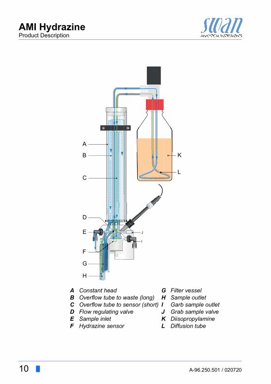
Fluidics The measurement of hydrazine requires a high pH of the sample. The AMI Hydrazine buffers the pH to pH>10.5 by adding diisopro-pylamine. The diisopropylamine is dissolved in the water while flowing through a diffusion tube.The sample enters at the sample inlet [E], passes the filter [G] and the flow regulating valve [D], where the sample flow can be adjust-ed. From there it flows through the diffusion tube [L] in the diisopro-pylamine bottle [K], picking up diisopropylamine and reaching pH>10.5. Afterwards, the sample is led directly into the shorter overflow tube [C]. From there it flows through the hydrazine sensor [F] and leaves the flow cell via sample outlet [H]. Excess sample overflows from the shorter overflow tube into the constant head [A], fills it until the sample overflows into the longer overflow tube. Sam-ple must always overflow into the longer overflow tube to ensure constant flow and pressure at the hydrazine sensor. The sample leaves the flow cell via sample outlet [H].
10 A-96.250.501 / 020720
AMI HydrazineProduct Description
ABCDEF
Constant headOverflow tube to waste (long)Overflow tube to sensor (short)Flow regulating valveSample inletHydrazine sensor
GHIJKL
Filter vesselSample outletGarb sample outletGrab sample valveDiisopropylamineDiffusion tube
A
B
C
D
F
E
G
H
I
J
K
L

AMI HydrazineProduct Description
A-96.250.501 / 020720 11
2.2. Instrument Specification
Power Supply AC variant:
DC variantPower consumption:
100–240 VAC (± 10%)50/60 Hz (± 5%)10–36 VDCmax. 35 VA
Transmitterspecifications
Housing:
Ambient temperature:Storage and transport:Humidity:Display:
aluminum, with a protection degree ofIP 66 / NEMA 4X−10 to +50 °C−30 to +85 °C10–90% rel., non condensingbacklit LCD, 75 x 45 mm
Measuringrange
Hydrazine
Range:Accuracy:
Stability:
Response time:
0.1–600 ppb5% of reading up to 200 ppb± 15% up to 600 ppbor ± 2 ppb (whichever is greater).±5% of reading per month, or ±2ppb per month90% of change in 60 sec after the sample entered the flow cell.
Measuringrange
temperature
Measuring range:Resolution:
up to 60°C0.1 °C
Samplerequirements
Flow rate:Temperature:Sample inlet pressure:Sample outlet pressure:pH value:
approx. 15 l/h15 to 45 °C0.15–2 barpressure freeequal or higher than pH 7.0
On-site The analyzer site must permit connections to:requirements Sample inlet:
Sample outlet:Serto 4x6 mmTube adapter 15x20 mm

12 A-96.250.501 / 020720
AMI HydrazineProduct Description
Dimensions Panel:Mounting hole distanceScrews:Weight:
280x850x180 mm, stainless steel254x8248 mm diameter12.0 kg
Exit Enter
AMI Hydrazine 13 m
m /
0.51
"4
x di
a. 1
0 m
m /
0.39
"
850
mm
/ 33
.46"
824
mm
/ 32
.44"
254 mm / 10.00"
280 mm / 11.02"

AMI HydrazineProduct Description
A-96.250.501 / 020720 13
2.3. Instrument Overview
ABCDEFGHIJ
PanelTransmitterBottle holderDiisoproylamine bottleDiffusion tubeReference electrodeGrab sample valveGrab sample outletFlow regulating valveHydrazine sensor
KLMNOPQRST
Filter vesselSample outletSample inletHall sensor (not visible)Flow cell blockConstant headOverflow tube to sensor (short)Overflow tube to waste (long)Constant head coverTemperature sensor
A
B
C
D
E
F
GHI
JKL
MN
O
PQ
R
ST

14 A-96.250.501 / 020720
AMI HydrazineInstallation
3. Installation
3.1. Installation Checklist Monitors
On site requirements
AC variant: 100–240 VAC ( 10%), 50/60 Hz ( 5%) DC variant: 10–36 VDCPower consumption: 35 VA maximum.Protective earth connection required.Sample line with sufficient sample flow and pressure (see Instru-ment Specification, p. 11).
Installation Mounting of Instrument Panel, p. 15.Connecting Sample and Waste, p. 15.
Electrodes Install the Reference Electrode, p. 16.Install the Temperature Sensor, p. 17.
Diisopropyl-amine
Install the Diisopropylamine Bottle, p. 28.
Electrical wiring
Connect all external devices like limit switches, current loops and pumps, see Connection Diagram, p. 20.Connect the power cord, see Power Supply, p. 21.
Power-up Establish Sample Flow, p. 29.Switch on power.Adjust sample flow according to flow cell specifications.
Instrument set-up
Program all necessary parameters see Programming, p. 29.Program all parameters for external devices (interface, record-ers, etc.).Program all parameters for instrument operation (limits, alarms).
Run-in period Let the instrument run-in for approximately 30 min continuous operation. See Run in period, p. 29.

AMI HydrazineInstallation
A-96.250.501 / 020720 15
3.2. Mounting of Instrument PanelThe first part of this chapter describes the preparing and placing ofthe system for use. The instrument must only be installed by trained personnel. Mount the instrument in vertical position. For ease of operation mount it so that the display is at eye
level. For the installation a kit containing the following installation
material is available:– 4 Screws 8x60 mm– 4 Dowels– 4 Washers 8.4/24 mm
Mountingrequirements
The instrument is only intended for indoor installation.
3.3. Connecting Sample and WasteSample inlet Slide the knurled nut [C] and the compression ferrule [B] over the
4x6 plastic tube [E]. Push it into the serto fitting [A] and tighten the knurled nut.
Waste Connect the 1/2” tube [F] to the hose nozzle [D] and place it into a pressure free drain.
A
BCD
EF
Serto fitting at sample inletCompression ferruleKnurled nutHose nozzle at sample outletPlastic tube 4x61/2” tube
A
D
E
BC
F

16 A-96.250.501 / 020720
AMI HydrazineInstallation
3.4. Install the Reference ElectrodeThe reference electrode is delivered separately and protected with a waterfilled protective cap. The connector is fixed to the panel with an adhesive tape and already connected to the front end PCB in the AMI transmitter.
To install the reference electrode proceed as follows:
1 Loosen the union nut [D].2 Remove the protective cap [B] from the reference electrode [C].3 Push the reference electrode through the union nut [D] into the
bore of the flow cell block [E] as far as it will go.4 Tighten the union nut.5 Remove the connector [A] from the panel and screw it onto the
reference electrode.
ABC
ConnectorProtective capReference sensor
DE
Union nutFlow cell block
C
B
DE
A

AMI HydrazineInstallation
A-96.250.501 / 020720 17
3.5. Install the Temperature SensorThe temperature sensor is fixed to the panel with an adhesive tape and already connected to the front end PCB in the AMI transmitter.
To install the temperature sensor proceed as follows:
1 Remove the temperature sensor [A] from the panel.2 Put the temperature sensor in the designated hole of the con-
stant head cover [B].3 Push it into the hole as far as it will go.
ABC
Temperature sensorConstant head coverConstant head
A
B
C

18 A-96.250.501 / 020720
AMI HydrazineInstallation
3.6. Electrical Connections
WARNING
Risk of electrical shock.Do not perform any work on electrical components if the trans-mitter is switched on. Failure to follow safety instructions canresult in serious injury or death. Always turn off power before manipulating electric parts. Grounding requirements: Only operate the instrument from a
power outlet which has a ground connection. Make sure the power specification of the instrument corre-
sponds to the power on site.
Cablethicknesses
In order to comply with IP66, use the following cable thicknesses
NOTICE: Protect unused cable glands
Wire For Power and Relays: Use max. 1.5 mm2 / AWG 14 stranded wire with end sleeves.
For Signal Outputs and Input: Use 0.25 mm2 / AWG 23 stranded wire with end sleeves.
ABC
PG 11 cable gland: cable Øouter 5–10 mmPG 7 cable gland: cable Øouter 3–6.5 mmPG 9 cable gland: cable Øouter 4–8 mm
A B C

AMI HydrazineInstallation
A-96.250.501 / 020720 19
WARNING
External Voltage.External supplied devices connected to relay 1 or 2 or to the alarm relay can cause electrical shocks Make sure that the devices connected to the following con-
tacts are disconnected from the power before resuming in-stallation.– relay 1– relay 2– alarm relay
WARNING
To prevent from electrical shock, do not connect the instrument to the power unless the groundwire (PE) is connected.
WARNING
The mains of the AMI transmitter must be secured by a main switch and appropriate fuse or circuit breaker.

20 A-96.250.501 / 020720
AMI HydrazineInstallation
3.6.1 Connection Diagram
CAUTION
Use only the terminals shown in this diagram, and only for the mentioned purpose. Use of any other terminals will cause short circuits with possible corresponding consequences to material and personnel.

AMI HydrazineInstallation
A-96.250.501 / 020720 21
3.6.2 Power Supply
WARNING
Electrical shock hazardInstallation and maintenance of electrical parts must be per-formed by professionals. Always turn off power before manipu-lating electric parts.
NOTICE: The protective earth wire (ground) has to be connected to the grounding terminal.
Installationrequirements
The installation must meet the following requirements. Mains cable to comply with standards IEC 60227 or IEC
60245; flammable rating FV1 Mains equipped with an external switch or circuit-breaker
– near the instrument– easily accessible to the operator– marked as interrupter for AMI Hydrazine
ABCD
Power supply connectorNeutral conductor, Terminal 2Phase conductor, Terminal 1Protective earth PE
A
B
C
D
22 A-96.250.501 / 020720
AMI HydrazineInstallation
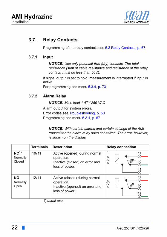
3.7. Relay ContactsProgramming of the relay contacts see 5.3 Relay Contacts, p. 67
3.7.1 InputNOTICE: Use only potential-free (dry) contacts. The total resistance (sum of cable resistance and resistance of the relay contact) must be less than 50 Ω.
If signal output is set to hold, measurement is interrupted if input is active.For programming see menu 5.3.4, p. 73
3.7.2 Alarm RelayNOTICE: Max. load 1 AT / 250 VAC
Alarm output for system errors.Error codes see Troubleshooting, p. 50Programming see menu 5.3.1, p. 67
NOTICE: With certain alarms and certain settings of the AMI transmitter the alarm relay does not switch. The error, however, is shown on the display.
1) usual use
Terminals Description Relay connectionNC1)
Normally Closed
10/11 Active (opened) during normal operation.Inactive (closed) on error and loss of power.
NONormallyOpen
12/11 Active (closed) during normal operation.Inactive (opened) on error and loss of power.
10
12
11
0V
1)
10
12
11
0V

AMI HydrazineInstallation
A-96.250.501 / 020720 23
3.7.3 Relay Contacts 1 and 2NOTICE: Rated load 1 AT / 250 VAC
Relay 1 and 2 can be configured as normally open or as normally closed. Standard for both relays is normally open. To configure a Relay as normally closed, set the jumper in the upper position.
NOTICE: Some error codes and the instrument status may influence the status of the relays described below.
For programming see Menu Installation 5.3.2 and 5.3.3, p. 69
Relay config. Terminals
Jumper pos. Description Relay configuration
NormallyOpen
6/7: Relay 18/9: Relay 2
Inactive (opened) during normal operation and loss of power.Active (closed) when a programmed function is executed.
NormallyClosed
6/7: Relay 18/9: Relay 2
Inactive (closed) during normal operation and loss of power.Active (opened) when a programmed function is executed.
6
0V7
6
0V7
AB
Jumper set as normally open (standard setting)Jumper set as normally closed
AB

24 A-96.250.501 / 020720
AMI HydrazineInstallation
CAUTION
Risk of damage of the relays in the AMI Transmitter due to heavy inductive load.Heavy inductive or directly controlled loads (solenoid valves, dosing pumps) may destroy the relay contacts. To switch inductive loads > 0.1 A use an AMI relay box avail-
able as an option or suitable external power relays.
Inductive load Small inductive loads (max 0.1 A) as for example the coil of a pow-er relay can be switched directly. To avoid noise voltage in the AMI Transmitter it is mandatory to connect a snubber circuit in par-allel to the load. A snubber is not necessary if an AMI relaybox is used.
Resistive load Resistive loads (max. 1 A) and control signals for PLC, impulse pumps and so on can be connected without further measures
Actuators Actuators, like motor valves, are using both relays: One relay con-tact is used for opening, the other for closing the valve, i.e. with the 2 relay contacts available, only one motor valve can be controlled. Motors with loads bigger than 0.1 A must be controlled via external power relays or an AMI relay box.
ABCDE
AC or DC power supplyAMI TransmitterExternal power relaySnubberPower relay coil
AB C
D E
ABC
AMI TransmitterPLC or controlled pulse pumpLogic
A B
C
ABC
AC or DC power supplyAMI TransmitterActuator
M
AB C

AMI HydrazineInstallation
A-96.250.501 / 020720 25
3.8. Signal Outputs
3.8.1 Signal Output 1 and 2 (current outputs)NOTICE: Max. burden 510 ΩIf signals are sent to two different receivers, use signal isolator (loop isolator).
Signal output 1: Terminals 14 (+) and 13 (-)Signal output 2: Terminals 15 (+) and 13 (-)For programming see Chapter 9, 5.2 Signal Outputs, p. 64, Menu Installation
3.9. Interface Options
The slot for interfaces can be used to expand the functionality of the AMI instrument with either: Third signal output a Profibus or Modbus connection an USB Interface a HART interface
ABCD
AMI TransmitterSlot for interfacesFrontend PCBScrew terminals
A
B
C
D
26 A-96.250.501 / 020720
AMI HydrazineInstallation
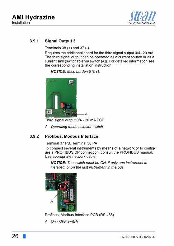
3.9.1 Signal Output 3Terminals 38 (+) and 37 (-).Requires the additional board for the third signal output 0/4–20 mA. The third signal output can be operated as a current source or as a current sink (switchable via switch [A]). For detailed information see the corresponding installation instruction.
NOTICE: Max. burden 510 Ω.
Third signal output 0/4 - 20 mA PCB
3.9.2 Profibus, Modbus InterfaceTerminal 37 PB, Terminal 38 PATo connect several instruments by means of a network or to config-ure a PROFIBUS DP connection, consult the PROFIBUS manual. Use appropriate network cable.
NOTICE: The switch must be ON, if only one instrument is installed, or on the last instrument in the bus.
Profibus, Modbus Interface PCB (RS 485)
A Operating mode selector switch
A
A On - OFF switch
ON
OFF
A

AMI HydrazineInstallation
A-96.250.501 / 020720 27
3.9.3 HART InterfaceTerminals 38 (+) and 37 (-).The HART interface PCB allows for communication via the HART protocol. For detailed information, consult the HART manual.
HART Interface PCB
3.9.4 USB InterfaceThe USB Interface is used to store Logger data and for Firmware upload. For detailed information see the corresponding installation instruction.The optional third signal output 0/4 – 20 mA PCB [B] can be plugged onto the USB interface and used in parallel.
USB Interface
A USB interface PCBB Third signal output 0/4 - 20 mA PCB
A
B

28 A-96.250.501 / 020720
AMI HydrazineInstrument Setup
4. Instrument Setup
4.1. Install the Diisopropylamine BottleOnly install the diisopropylamine bottle if you intend to start opera-tion immediately. Do not it install if no sample in available!Fill the Diisopropylamine into the glass bottle (G45 thread), deliv-ered with the instrument. If you want to connect a Merck bottle di-rectly, you need a thread adapter which can be ordered at SWAN, order number C-83.591.010.
WARNING
Diisopropylamine is corrosive. Read the Safety Data Sheets (SDS) first. Wear suitable protective clothing, gloves and eye/face pro-
tection. Avoid inhalation of DIPA vapor. To prevent formation of re-
agent vapors:– close the reagent bottle firmly– check the EPDM seal regularly
In case of contact with eyes, rinse immediately with plenty of water eyelid wide open for at least 10 min, summon medical advice. In case of accident or if you feel unwell, summon medical advice immediately (show the label where possible).
ABCDEF
Bottle holderScrew cover G 45EPDM seal mounted on the bottle holderReagent bottleSteel tubeDiffusions tube
ABC
DE
F

AMI HydrazineInstrument Setup
A-96.250.501 / 020720 29
1 Fill roughly 750 ml high purity water into a 1 l beaker.2 Dip the diffusion tube [F] into the beaker filled with high purity
water and rinse it some seconds.3 Push the diffusion tube over the steel tubes [E].4 Open the reagent bottle [D], add 20 ml of high purity water.5 Screw the reagent bottle into the screw cover [B], fixed to the
bottle holder [A]6 Make sure that the diffusions tube [F] is placed in the reagent
bottle as shown in the picture above.7 Tighten the screw cover well.
4.2. Establish Sample Flow1 Make sure, that the grab sample valve is closed.2 Open the flow regulating valve.3 Wait until the flow cell is completely filled.4 Switch on power.
4.3. ProgrammingProgram all parameters for external devices (interface, recorders, etc.). Program all parameters for instrument operation (limits, alarms). For explanations, see Program List and Explanations, p. 61.
4.4. Run in periodLet the instrument run-in for approximately 30 min continuous oper-ation (flow on, power on). The Diisopropylamine needs roughly 30 min to penetrate the walls of new diffusion tubes.

30 A-96.250.501 / 020720
AMI HydrazineInstrument Setup
4.5. Correction of Hydrazine SensorIf necessary, correct the instrument after at least 30 min running-in. To correct the instrument the concentration of hydrazine in the sam-ple has to be known. Hydrazine reacts with dimethylaminobenzal-dehyde in an acid solution and forms a yellow color. The color intensity can be measured by a photometer. Refer to an appropri-ate standard method (e.g. DIN 38413). The manual sample must be taken from the grab sample outlet of the flow cell. Let the sample flow out for roughly 1 minute before grabbing the sample for the manual analysis.See Calibration of Hydrazine Sensor, p. 46.

AMI HydrazineOperation
A-96.250.501 / 020720 31
5. Operation
5.1. Keys
ProgramAccess, Exit
A to exit a menu or command (rejecting any changes)to move back to the previous menu level
B to move DOWN in a menu list and to decrease digits
C to move UP in a menu list and to increase digits
D to open a selected sub-menuto accept an entry
Exit Enter
B C DA
25.4°C
RUN
9 l/h
14:10:45R1
0.45 ppmR2
1
InstallationOperation
DiagnosticsMessages
Maintenance
Main MenuEnter
Exit

32 A-96.250.501 / 020720
AMI HydrazineOperation
5.2. Display
Relay status, symbols
A RUN normal operation
HOLD input closed or cal delay: Instrument on hold (shows status of signal outputs).
OFF input closed: control/limit is interrupted (shows status of signal outputs).
B ERROR Error Fatal Error
C Keys locked, transmitter control via Profibus
D Time
E Process values
F Sample temperature
G Sample flow
H Relay status
upper/lower limit not yet reachedupper/lower limit reachedcontrol upw./downw. no action
control upw./downw. active, dark bar indicates control intensity
motor valve closedmotor valve: open, dark bar indicates approx. positiontimertimer: timing active (hand rotating)
RUN 15:20:18
R1
R2
360 rpm 24.8°C
ppb0.45
A B
E
FGH
DC

AMI HydrazineOperation
A-96.250.501 / 020720 33
5.3. Software Structure
Menu Messages 1Reveals pending errors as well as an event history (time and state of events that have occurred at an earlier point of time). It contains user relevant data.
Menu Diagnostics 2Provides user relevant instrument and sample data.
Menu Maintenance 3For instrument calibration, relay and signal output simulation, and to set the instrument time. It is used by the service personnel.
Menu Operation 4User relevant parameters that might need to be modified during daily routine. Normally password protected and used by the process-operator.Subset of menu 5 - Installation, but process-related.
Menu Installation 5For initial instrument set up by SWAN authorized person, to set all instrument parameters. Can be protected by means of password.
1
Messages
OperationMaintenanceDiagnostics
Main Menu
Installation
1.1
Pending ErrorsMessages
Message List
2.1
InterfaceI/O StateSample
IdentificationSensors
Diagnostics
3.1
CalibrationMaintenance
Set Time 23.09.06 16:30:00Simulation
4.1
LoggerRelay ContactsSensorsOperation
5.1
InterfaceMiscellaneousRelay Contacts
SensorsSignal Outputs
Installation

34 A-96.250.501 / 020720
AMI HydrazineOperation
5.4. Changing Parameters and valuesChanging
parametersThe following example shows how to change the logger interval:
Changingvalues
1 Select the parameter you want to change.
2 Press [Enter]
3 Press [ ] or [ ] key to highlight the required parameter.
4 Press [Enter] to confirm the selec-tion or [Exit] to keep the previous parameter.
The selected parameter is highlighted (but not saved yet).
5 Press [Exit].
Yes is highlighted.6 Press [Enter] to save the new pa-
rameter. The system reboots, the new
parameter is set.
5.1.2SensorsSensor type FOME
Temperature NT5KStandards
Disinf. Free chlorine
4.4.1LoggerLog interval 30 minClear logger no
4.1.3Logger
Clear logger noLog interval 30min
1 Hour
Interval.5 min
30 min10 min
4.1.3LoggerLog interval 10 minClear logger no
4.1.3LoggerLog intervalClear logger no
No
Save ?Yes
1 Select the value you want to change.
2 Press [Enter].3 Set required value with [ ] or
[ ] key.
4 Press [Enter] to confirm the new value.
5 Press [Exit]. Yes is highlighted.
6 Press [Enter] to save the new val-ue.
5.3.1.1.1
Alarm High 10.0 ppmAlarm Hydrazine
Alarm Low 0.000 ppmHysteresis 10.0 ppmDelay 5 Sec
5.3.1.1.1Alarm Hydrazine
Alarm Low 0.000 ppmHysteresis 10.0 ppmDelay 5 Sec
Alarm High 6.00 ppm
AMI HydrazineMaintenance
A-96.250.501 / 020720 35
6. Maintenance
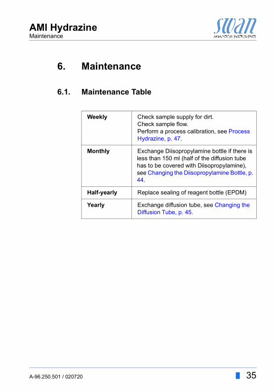
6.1. Maintenance Table
Weekly Check sample supply for dirt.Check sample flow.Perform a process calibration, see Process Hydrazine, p. 47.
Monthly Exchange Diisopropylamine bottle if there is less than 150 ml (half of the diffusion tube has to be covered with Diisopropylamine), see Changing the Diisopropylamine Bottle, p. 44.
Half-yearly Replace sealing of reagent bottle (EPDM)
Yearly Exchange diffusion tube, see Changing the Diffusion Tube, p. 45.

36 A-96.250.501 / 020720
AMI HydrazineMaintenance
6.2. Stop of Operation for Maintenance
WARNING
Diisopropylamine is corrosive. Read the Safety Data Sheets (SDS) first. Wear suitable protective clothing, gloves and eye/face pro-
tection. Avoid inhalation of DIPA vapor. In case of contact with eyes, rinse immediately with plenty of
water eyelid wide open for at least 10 min, summon medical advice. In case of accident or if you feel unwell, summon medical advice immediately (show the label where possible).
1 Wear safety gloves and safety glasses!2 Remove the diisopropylamine bottle and close it well. 3 Screw an empty bottle on the holder. Let the sample run for 30
min.4 Stop sample flow by closing the flow regulating valve. 5 Wait until the rotor stops and hydrazine reading is 0 ppb.6 Shut off power of the instrument.7 Empty the constant head by opening the grab sample tap.

AMI HydrazineMaintenance
A-96.250.501 / 020720 37
6.3. Cleaning of the Protective Filter
If the protection filter shows deposits, proceed as follows:
1 Close the flow regulating valve [A].2 Close the sample main tap before the filter.3 Unscrew and remove the filter vessel [C] from the flow cell
block.4 Unscrew and remove the filter from [B] the flow cell block.5 Backwash the filter under pressure of tap water. Clean the out-
side of the filter.6 Install the filter and filter vessel again.7 Open sample supply and flow regulating valve again.
ABC
Flow regulating valveFilterFilter vessel
A
B
C

38 A-96.250.501 / 020720
AMI HydrazineMaintenance
6.4. Cleaning of the Hydrazine Sensor
1 Close the flow regulating vale [A].2 Wait until rotor [C] stops and hydrazine reading is 0 ppm.3 Shut off power of the instrument.4 Disconnect the BNC connector [G] from the hydrazine sensor
[F].Prevent the connector from getting wet.
5 Unscrew and remove one of the two knurled nuts [H].
ABCD
Flow regulating valveThreaded boltRotorO-Ring
EFGH
OrificesHydrazine sensorBNC connectorKnurled nut
A
B
C
G
FFE
CB
D
H H
D
E

AMI HydrazineMaintenance
A-96.250.501 / 020720 39
CAUTION
Avoid damaging of the hydrazine sensor during removal. Once damaged, the sensor needs to be replaced.
Do not touch the platinum ring in the center of the hydrazine sensor with your fingers or metallic objects.
6 Hold the hydrazine sensor [F] with one hand while unscrewing and removing the 2nd knurled nut.
7 Remove the hydrazine sensor from the flow cell.Take care not to spill the sample remaining in the sensor.
Cleaning 1 Remove the rotor [C] from the hydrazine sensor.2 Clean the tow orifices [E] with a pipe cleaner or a toothpick3 Clean the rotor with a soft tissue.4 Cautiously wipe the sensor with a soft tissue, mainly the plati-
num parts and the whole area which is in contact with water.5 After cleaning rinse all parts well with clean water.
Install 1 Put rotor on the sensor.2 Install the sensor into the flow cell. 3 Fasten the knurled nuts hand-tight.4 Connect the BNC connector to the hydrazine sensor.5 Open the sample flow.6 As soon as the rotor is turning, switch on power.
NOTICE: After cleaning the sensor, the measured value may be too high. Let the instrument run for about 24 h.

40 A-96.250.501 / 020720
AMI HydrazineMaintenance
6.5. Cleaning of Reference Electrode
1 Close the flow regulating vale.2 Loosen the union screw [B].3 Pull the reference electrode out.4 Wipe sensor tip cautiously with a soft tissue. If necessary use
alcohol to remove oily deposits.Do not use any acid!
5 Push the reference electrode through the union screw into the flow cell as far as it will go.
6 Tighten the union screw.
AB
Reference electrodeUnion screw
EF
WasherO-Ring
CD
B
A

AMI HydrazineMaintenance
A-96.250.501 / 020720 41
6.6. Cleaning of Flow Cell
CAUTION
Never use organic solvents or scrubbing materials to clean acrylic glass parts.
Use soft detergent and rinse well. Eliminate calcareous de-posits with a common household deliming agent in standard concentration.
ABC
DEF
GHIJKLMNOPQR
Temperature senorTube from sample inletTube to hydrazine sensorConstant head coverConstant head tubeConstant head tube fixationOverflow tube to wasteOverflow tube to sensorFlow cell blockGrab sample tapFixing screwFlow regulating valveSample InletHall sensorFilterFilter vesselHydrazine sensorSample outlet
A
BCD
EF
G
H
IJKLMNO
PQ
R

42 A-96.250.501 / 020720
AMI HydrazineMaintenance
Disassemblethe flow cell
1 Switch off the instrument.2 Stop the sample flow at the main tap before the sample inlet.3 Open the grab sample tap [J] to empty the flow cell.4 Remove all sensors, see Cleaning of the Hydrazine Sensor, p.
38, Cleaning of Reference Electrode, p. 40 and temperature sensor.
5 Put the rubber cap on the tip of the reference electrode and plug cap on sensor plug.
6 Remove the following parts from the flow cell block [I], but with-out however removing the flow cell block from the panel:–Tube from sample inlet to DIPA bottle [B]–Tube from DIPA bottle to hydrazine sensor [C]–Constant head cover [D]–Constant head tube [E]–Overflow tube to waste (long) [G]–Overflow tube to sensor (short) [H]–Grab sample tap [J]–Sample inlet [M] and grab sample outlet (not visible)–Filter vessel [P]–Filter [O]–Sample outlet [R]–Hall-Effect sensor [N]–Flow regulating valve [L]
7 Clean all acrylic parts with a soft brush (e.g. a bottle cleaner) and soapy water. Remove calcareous deposits with a common household deliming agent with standard concentrations.
8 Clean the bores of the flow cell block with pipe cleaners.

AMI HydrazineMaintenance
A-96.250.501 / 020720 43
Assemble theflow cell
1 Wrap 7 turns of teflon tape around the hose nozzle thread2 Replace all o-rings and grease them with teflon paste.3 Assemble the flow cell.4 Install all sensors.5 Open the main tap and wait until the flow cell is filled6 Check all connection for leakage, if necessary retighten leaky
points.7 Switch on the instrument.
ABC
Teflon bandHose nozzle at sample outletSerto fitting at sample inlet and grab sample outletC
B
A

44 A-96.250.501 / 020720
AMI HydrazineMaintenance
6.7. Changing the Diisopropylamine BottleShut down the instrument as described in Stop of Operation for Maintenance, p. 36.Consider the Warning concerning Diisopropylamine handling.
1 Fill roughly 750 ml high purity water into a 1 l beaker.2 Unscrew and remove the almost empty reagent bottle [D].3 Close the reagent bottle immediately.4 Check the EPDM seal [C] for cracks an replace it if necessary.5 Remove the diffusion tube [F] from the steel tubes [E].6 Dip the diffusion tube into the beaker filled with high purity wa-
ter. Rinse some seconds.7 Push the diffusion tube over the steel tubes.8 Open the new reagent bottle and add 20 ml of high purity water.
NOTICE: If you fill up Diisopropylamine into the almost empty bottle, no high purity water needs to be added.
9 Slide the reagent bottle over the diffusions tube and ensure that it lies pretzel-shaped in the reagent bottle.
10 Fasten bottle to the bottle holder.11 The liquid in the almost empty Diisopropylamine bottle must be
disposed as chemical waste.
ABCDEF
Bottle holderScrew cover G 45EPDM seal mounted on the bottle holderReagent bottleSteel tubeDiffusions tube
ABC
DE
F

AMI HydrazineMaintenance
A-96.250.501 / 020720 45
6.8. Changing the Diffusion TubeShut down the instrument as described in Stop of Operation for Maintenance, p. 36.Consider the Warning concerning Diisopropylamine handling.
The correct measuring value will appear after 30 min of continuous operation (flow and power on). Diisopropylamine needs roughly 30 min to penetrate the walls of the new diffusion tube.
1 Fill roughly 750 ml high purity water into a 1 l bea-ker.
2 Unscrew and remove Diisopropylamine bottle from the holder.
3 Close the bottle immediately.4 Remove the old diffusion tube from the steel
tubes.5 Dip the new diffusion tube into the beaker filled
with high purity water and rinse it some seconds.6 Push the new diffusion tube over the steel tubes.7 Open the reagent bottle and slide it over the diffu-
sions tube.NOTICE: Ensure that the diffusions tube lies pretzel-shaped in the reagent bottle as shown in the picture.
8 Screw the bottle into the holder.

46 A-96.250.501 / 020720
AMI HydrazineMaintenance
6.9. Calibration of Hydrazine Sensor
6.9.1 Calibration ProcedureManual
MeasurementHydrazine reacts with dimethylaminobenzaldehyde in an acid solu-tion and forms a yellow colour. The colour intensity is proportional to the concentration and can be determined by a photometer. Refer to an appropriate standard method.
Correction The adjustment of the slope is called correction. The zero remains unchanged.
6.9.2 Zero HydrazineA zero point calibration is not necessary.If your quality procedure specifies a zero point calibration, please proceed as described below:
NOTICE: Let the instrument run continuously for at least 5 days in normal operation before doing a zero point calibration!
1 Navigate to menu <Maintenance>/<Calibration>/<Zero Hydra-zine>.
2 Press [Enter].3 Follow the instructions on the screen.
During a zero calibration, the sample flow is turned off and the re-sidual hydrazine in the small water volume around the sensor is consumed within 15–20 min. 0 ppb remains and after 30 min, a zero calibration is performed.Current value / offset (Progress of zero cal. is shown). Wait until fin-ished.Open tap of the water inlet and regulate the sample flow.

AMI HydrazineMaintenance
A-96.250.501 / 020720 47
6.9.3 Process HydrazineThe sample must always overflow into the longer overflow tube of the constant head. Only perform process calibration if the differ-ence is significant.
Grab sample Take a grab sample directly from the flow cell. Open the grab sam-ple valve and drain water for a minute before taking the sample. Observe the displayed value of the AMI Hydrazine while taking the grab sample. The measuring value has to be stable. Determine the hydrazine concentration of the sample by manual analysis.Compare the result with the measuring value of the AMI Hydrazine.If the measuring value of the AMI Hydrazine has changed while performing the manual analysis, enter the difference between the measuring values of the AMI Hydrazine.
Example Displayed measuring value of AMI Hydrazine during grab sample: 10 ppb.Displayed measuring value of AMI Hydrazine after concentration determination: 15 ppb.Determined hydrazine concentration: 8 ppb.There is a change of the measurement value of 50% during the concentration determination. This means, you have to correct the determined hydrazine concentration also with a factor of 50%.This will result in a value of 8 ppb + (50% of 8 ppb) = 12 ppb.Finally, you have to enter 12 ppb as a process value at the AMI transmitter.
Example ofProcess
Calibration
1 Navigate to menu <Maintenance>/<Calibration>.
2 Press [Enter].
1 Select Process Hydrazine.2 Press [Enter].
3.1
CalibrationSimulation
Maintenance
Set Time 01.01.05 16:30:00
Calibration
3.1.1CalibrationZero HydrazineProcess Hydrazine

48 A-96.250.501 / 020720
AMI HydrazineMaintenance
During calibration, control is interrupted. The signal outputs are fro-zen if hold after calibration has been programmed (menu 4.3.4.2). Otherwise the outputs track the measuring value. Hold after calibra-tion is indicated by Hold in the display.
Possible error message see Troubleshooting, p. 50.
The following values are displayed: Current value Raw value Process valueCurrent value and Process value are equal.3 Press [Enter].4 Enter the calculated value.
Use the [ ] or [ ] keys to increase or decrease the Process value.
5 Press [Enter] to save.
Process Hydrazine
Raw value x µA
Save <Enter>Process Value 18.80 ppm
3.1.4.1
Current Value 18.80 ppb
Process HydrazineCurrent Value 18.8 ppbRaw value x nA
Save <Enter>Process Value 24.0 ppb
3.1.2.5
3.1.4.1Process HydrazineCurrent Value 18.80 ppbRaw value x µA
Process Value 24.0 ppbSave <Enter>
3.1.4.1Process HydrazineCurrent Value 15 ppbRaw value x µA
Calibration successful

AMI HydrazineMaintenance
A-96.250.501 / 020720 49
6.10. Longer Stop of OperationDo not switch off the instrument if your operation is suspended for less than a week. Power consumption is very low, and the sensors remain ready for use.Shut-down the instrument as described in chapter Stop of Opera-tion for Maintenance, p. 36.Consider the Warning concerning Diisopropylamine handling.
Then:1 Remove the Diisopropylamine bottle from the bottle holder and
close it well.2 Remove the diffusion tube from the steel tubes and dip it into a
beaker filled with high purity water. Rinse it some seconds.3 Unscrew and remove the filter vessel from the flow cell block,
empty and dry it, then screw it onto the flow cell block again.4 Loosen the connector from the reference electrode and put the
connector cap on the electrode plug.Do not spill water on connector.
5 Remove the reference electrode from the flow cell block, fill wa-ter in the protective cap and put the protective cap on the elec-trode tip.
6 Store it dry and frost protected with tip pointing downwards.7 Remove the BNC connector from the hydrazine sensor.
Do not spill water on connector.8 Hold the hydrazine sensor with one hand while unscrewing and
removing the 2nd knurled nut.9 Remove the hydrazine sensor from the flow cell.10 Dry it with a soft, clean tissue, and store dry.

50 A-96.250.501 / 020720
AMI HydrazineTroubleshooting
7. Troubleshooting
This chapter provides some hints to make troubleshooting easier. For any detailed information how to handle or clean parts please see Maintenance, p. 35. For any detailed information how to program the instrument please see Program List and Explanations, p. 61.
Processcalibration
Possible error message Current value too low or no sample flow. Offset Error Slope Error
Current value too low or no sample flow:
Offset Error:
Possible cause Corrective actionThe ppb value of the sample is too low, thereby, the current dif-ference to zero is too small.
Process value used for calibration should be higher.
Check the diagnostic value of the zero point.
Low sample flow resulting in no signal difference to zero.
Check sample inlet pressure, if necessary readjust sample flow to min. 170 rpm.
Hydrazine sensor contaminatedSensor does not provide enough current for the value measured with the manual analysis.
Clean sensor, see Cleaning of the Hydrazine Sensor, p. 38. In case of repeated sensor con-tamination, check for water treat-ment chemicals such as phosphates.
Possible cause Corrective actionRun-in time of sensor to short. Let the sensor run-in at least 30
minZero point calibration was too short.
Repeat the zero point calibration

AMI HydrazineTroubleshooting
A-96.250.501 / 020720 51
Slope Error:
Referenceelectrode
The reference electrode may be old or damaged. Under the follow-ing conditions the reference voltage should be:In water < 10 ppb oxygen and about 70 ppb hydrazine: ~ 1300 mVIn water with oxygen: ~ 400 mVCE (counter electrode) value: 200–400 mV Lower values indicate coated hydrazine sensors.
Diagnosticvalues
Offset: The offset is approx. 50 nAAn offset calibration is only necessary for Hydrazine values lower than 0.05 ppb. Running Time at least 24 hours.Slope: The slope is approx. 55 nA/ppb.
NOTICE: Observe the running in time.A decreasing slope value over several process calibrations indicates coating of sensor.Slope (and Zero) too high usually indicates that the running in time was too short.
Possible cause Corrective actionDiisopropylamine bot-tle empty
Exchange Diisopropylamine bottle, see Changing the Diisopropylamine Bottle, p. 44 or Install the Diisopropylamine Bottle, p. 28.
Insufficient immersion depth of the diffusion tube.
Place the diffusion Tube correct, see Changing the Diffusion Tube, p. 45.
Orifices at sensor inlet clogged
Clean the senor, see Cleaning of the Hydrazine Sensor, p. 38.
Run-in time of diffu-sions tube too short
After replacing the diffusions tube let the instrument run in at least 30 min
Too much water in the Diisopropylamine bot-tle.
Check diffusion tube for leakage and replace it if necessary, see Changing the Diffusion Tube, p. 45.Install a new DIPA-bottle, see Install the Diisopropylamine Bottle, p. 28.
Sample flow too high. Readjust the sample flow to min. 170 rpmSample flow too low Sample flow must not be smaller than
170 rpm. Readjust sample flow to min. 170 rpm.

52 A-96.250.501 / 020720
AMI HydrazineTroubleshooting
7.1. Error ListError Non-fatal Error. Indicates an alarm if a programmed value is ex-ceeded.Such Errors are marked E0xx (bold and black).Fatal Error (blinking symbol)Control of dosing devices is interrupted.The indicated measured values are possibly incorrect.Fatal Errors are divided in the following two categories: Errors which disappear if correct measuring conditions are re-
covered (i.e. Sample Flow low).Such Errors are marked E0xx (bold and orange)
Errors which indicate a hardware failure of the instrument.Such Errors are marked E0xx (bold and red)
Error or fatal ErrorError not yet acknowledged.Check Pending Errors 1.1.5 * and take corrective action.Press [ENTER].
Navigate to menu <Messages>/<Pending Errors>.
Press [ENTER] to acknowledge the Pending Errors.
The Error is reset and saved in the Message List.
23 °C
HOLD
80 rpm
14:10:45R1
0.5 ppbR2
1.1
Maintenance ListPending ErrorsMessages
Message List
1.1.5Pending ErrorsError Code E002
Alarm low
<Enter> to Acknowledge

AMI HydrazineTroubleshooting
A-96.250.501 / 020720 53
Error Description Corrective actionE001 Hyd. Alarm high – check process
– check programmed value 5.3.1.1.1, p. 68
E002 Hyd. Alarm low – check process– check programmed value 5.3.1.1.25, p.
68
E007 Sample Temp. high – check process– check programmed value 5.3.1.3.1, p.
69
E008 Sample Temp. low – check process– check programmed value 5.3.1.1.25, p.
68
E009 Sample Flow high – check Inlet pressure– readjust sample flow– check programmed value 5.3.1.2.2, p.
68
E010 Sample Flow low – check Inlet pressure– readjust sample flow– clean instrument– check programmed value 5.3.1.2.35, p.
69
E011 Temp. shorted – Check wiring of temperature sensor, see Connection Diagram, p. 20.
– Check sensor
E012 Temp. disconnected – Check wiring of temperature sensor, see Connection Diagram, p. 20.
– Check sensor
E013 Case Temp. high – check case/environment temperature– check programmed value 5.3.1.4, p. 69
E014 Case Temp. low – check case/environment temperature– check programmed value 5.3.1.5, p. 69

54 A-96.250.501 / 020720
AMI HydrazineTroubleshooting
E015 Reference – Check conductivity value of sample (must be > 5 µS/cm)
– Check gain of hydrazine sensor. If too small, clean hydrazine sensor.
– Exchange reference electrode.
E017 Control Timeout – check control device or programming in Installation, Relay contact, Relay 1/2 see 5.3.2 and 5.3.3, p. 69
E024 Input active – See If Fault Yes is programmed in Menu see 5.3.4, p. 73
E026 IC LM75 – call service
E028 Signal output open – check wiring on signal outputs 1 and 2
E030 EEProm Frontend – call service
E031 Calibration Recout – call service
E032 Wrong Frontend – call service
E033 Power-on – none, normal status
E034 Power-down – none, normal status
Error Description Corrective action

AMI HydrazineTroubleshooting
A-96.250.501 / 020720 55
7.2. Replacing Fuses
WARNING
External Voltage.External supplied devices connected to relay 1 or 2 or to the alarm relay can cause electrical shocks. Make sure that the devices connected to the following con-
tacts are disconnected from the power before resuming in-stallation.– relay 1– relay 2– alarm relay
When a fuse has blown, find out the cause and fix it before replac-ing it with a new one.Use tweezers or needle-nosed pliers to remove the defective fuse. Use original fuses provided by SWAN only.
A
BCDEFG
AC variant: 1.6 AT/250 V Instrument power supplyDC variant: 3.15 AT/250 V Instrument power supply1.0 AT/250V Relay 11.0 AT/250V Relay 21.0 AT/250V Alarm relay1.0 AF/125V Signal output 21.0 AF/125V Signal output 11.0 AF/125V Signal output 3
A B C D E F G

56 A-96.250.501 / 020720
AMI HydrazineProgram Overview
8. Program Overview
For explanations about each parameter of the menus see Program List and Explanations, S. 61.
Menu 1 Messages informs about pending errors and mainte-nance tasks and shows the error history. Password protection possible. No settings can be modified.
Menu 2 Diagnostics is always accessible for everybody. No password protection. No settings can be modified.
Menu 3 Maintenance is for service: Calibration, simulation of outputs and set time/date. Please protect with password.
Menu 4 Operation is for the user, allowing to set limits, alarm values, etc. The presetting is done in the menu Installation (only for the System engineer). Please protect with password.
Menu 5 Installation: Defining assignment of all inputs and outputs, measuring parameters, interface, passwords, etc. Menu for the system engineer. Password strongly recom-mended.
8.1. Messages (Main Menu 1)
Pending Errors Pending Errors 1.1.5* * Menu numbers1.1*Message List Number 1.2.1*1.2* Date, Time
AMI HydrazineProgram Overview
A-96.250.501 / 020720 57
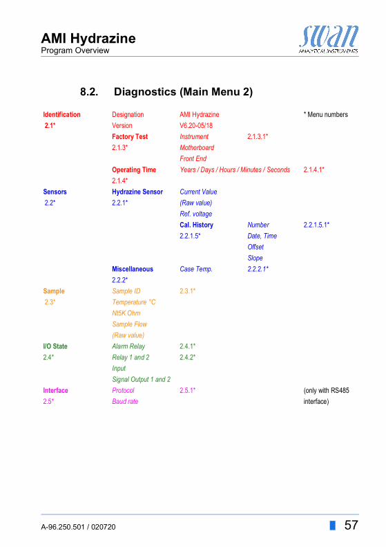
8.2. Diagnostics (Main Menu 2)
Identification Designation AMI Hydrazine * Menu numbers 2.1* Version V6.20-05/18
Factory Test Instrument 2.1.3.1*2.1.3* Motherboard
Front EndOperating Time Years / Days / Hours / Minutes / Seconds 2.1.4.1*2.1.4*
Sensors Hydrazine Sensor Current Value 2.2* 2.2.1* (Raw value)
Ref. voltageCal. History Number 2.2.1.5.1*2.2.1.5* Date, Time
OffsetSlope
Miscellaneous Case Temp. 2.2.2.1*2.2.2*
Sample Sample ID 2.3.1* 2.3* Temperature °C
Nt5K OhmSample Flow(Raw value)
I/O State Alarm Relay 2.4.1*2.4* Relay 1 and 2 2.4.2*
InputSignal Output 1 and 2
Interface Protocol 2.5.1* (only with RS4852.5* Baud rate interface)
58 A-96.250.501 / 020720
AMI HydrazineProgram Overview
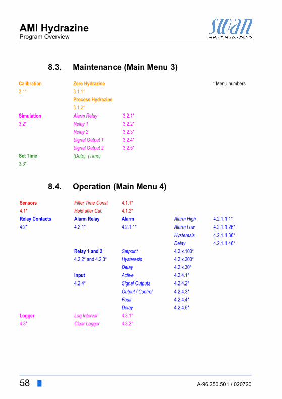
8.3. Maintenance (Main Menu 3)
8.4. Operation (Main Menu 4)
Calibration Zero Hydrazine * Menu numbers3.1* 3.1.1*
Process Hydrazine3.1.2*
Simulation Alarm Relay 3.2.1*3.2* Relay 1 3.2.2*
Relay 2 3.2.3*Signal Output 1 3.2.4*Signal Output 2 3.2.5*
Set Time (Date), (Time)3.3*
Sensors Filter Time Const. 4.1.1*4.1* Hold after Cal. 4.1.2*Relay Contacts Alarm Relay Alarm Alarm High 4.2.1.1.1*4.2* 4.2.1* 4.2.1.1* Alarm Low 4.2.1.1.26*
Hysteresis 4.2.1.1.36*Delay 4.2.1.1.46*
Relay 1 and 2 Setpoint 4.2.x.100*4.2.2* and 4.2.3* Hysteresis 4.2.x.200*
Delay 4.2.x.30*Input Active 4.2.4.1*4.2.4* Signal Outputs 4.2.4.2*
Output / Control 4.2.4.3*Fault 4.2.4.4*Delay 4.2.4.5*
Logger Log Interval 4.3.1*4.3* Clear Logger 4.3.2*
AMI HydrazineProgram Overview
A-96.250.501 / 020720 59
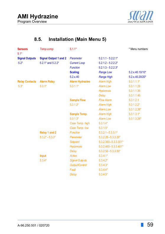
8.5. Installation (Main Menu 5)
Sensors Temp.comp 5.1.1* * Menu numbers5.1*Signal Outputs Signal Output 1 and 2 Parameter 5.2.1.1 - 5.2.2.1* 5.2* 5.2.1* and 5.2.2* Current Loop 5.2.1.2 - 5.2.2.2*
Function 5.2.1.3 - 5.2.2.3*Scaling Range Low 5.2.x.40.10/10*5.2.x.40 Range High 5.2.x.40.20/20*
Relay Contacts Alarm Relay Alarm Hydrazine Alarm High 5.3.1.1.1* 5.3* 5.3.1* 5.3.1.1* Alarm Low 5.3.1.1.26
Hysteresis 5.3.1.1.36Delay 5.3.1.1.46
Sample Flow Flow Alarm 5.3.1.2.15.3.1.2* Alarm High 5.3.1.2.2*
Alarm Low 5.3.1.2.36*Sample Temp. Alarm High 5.3.1.3.1*5.3.1.3* Alarm Low 5.3.1.3.26*Case Temp. high 5.3.1.4*Case Temp. low 5.3.1.5*
Relay 1 and 2 Function 5.3.2.1–5.3.3.1*5.3.2* - 5.3.3* Parameter 5.3.2.20–5.3.3.20*
Setpoint 5.3.2.300–5.3.3.301*Hysteresis 5.3.2.400–5.3.3.401*Delay 5.3.2.50–5.3.3.50*
Input Active 5.3.4.1*5.3.4* Signal Outputs 5.3.4.2*
Output/Control 5.3.4.3*Fault 5.3.4.4*Delay 5.3.4.5*

60 A-96.250.501 / 020720
AMI HydrazineProgram Overview
Miscellaneous Language 5.4.1* * Menu numbers5.4* Set defaults 5.4.2*
Load Firmware 5.4.3*Password Messages 5.4.4.1*5.4.4* Maintenance 5.4.4.2*
Operation 5.4.4.3*Installation 5.4.4.4*
Sample ID 5.4.5*Line break detection 5.4.6*
Interface Protocol 5.5.1* (only with RS485,5.5* Device Address 5.5.21* interface)
Baud Rate 5.5.31*Parity 5.5.41*
AMI HydrazineProgram List and Explanations
A-96.250.501 / 020720 61
9. Program List and Explanations
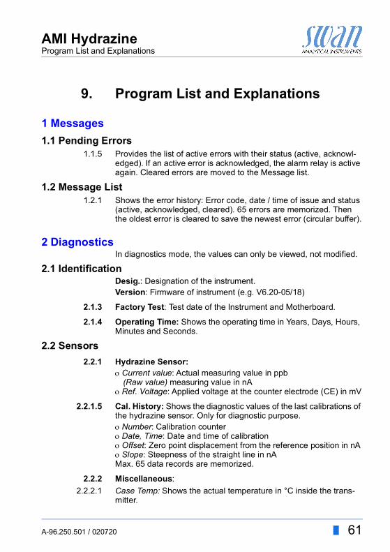
1 Messages1.1 Pending Errors
1.1.5 Provides the list of active errors with their status (active, acknowl-edged). If an active error is acknowledged, the alarm relay is active again. Cleared errors are moved to the Message list.
1.2 Message List1.2.1 Shows the error history: Error code, date / time of issue and status
(active, acknowledged, cleared). 65 errors are memorized. Then the oldest error is cleared to save the newest error (circular buffer).
2 DiagnosticsIn diagnostics mode, the values can only be viewed, not modified.
2.1 IdentificationDesig.: Designation of the instrument.Version: Firmware of instrument (e.g. V6.20-05/18)
2.1.3 Factory Test: Test date of the Instrument and Motherboard.
2.1.4 Operating Time: Shows the operating time in Years, Days, Hours, Minutes and Seconds.
2.2 Sensors2.2.1 Hydrazine Sensor:
Current value: Actual measuring value in ppb(Raw value) measuring value in nA
Ref. Voltage: Applied voltage at the counter electrode (CE) in mV
2.2.1.5 Cal. History: Shows the diagnostic values of the last calibrations of the hydrazine sensor. Only for diagnostic purpose.Number: Calibration counterDate, Time: Date and time of calibrationOffset: Zero point displacement from the reference position in nASlope: Steepness of the straight line in nAMax. 65 data records are memorized.
2.2.2 Miscellaneous:2.2.2.1 Case Temp: Shows the actual temperature in °C inside the trans-
mitter.

62 A-96.250.501 / 020720
AMI HydrazineProgram List and Explanations
2.3 Sample2.3.1 Sample ID: Shows the assigned sample identification. This
identification is defined by the user to identify the location of the sample
Temperature: Shows temperature in °C.(Nt5K): Shows raw value of the temperature in Ω.
Sample Flow: Shows the sample Flow in rpm(Raw value) Shows the sample Flow in Hz
2.4 I/O StateShows actual status of all in- and outputs.
2.4.1
2.5 InterfaceOnly available if optional interface is installed.Review programmed communication settings.
3 Maintenance3.1 Calibration
3.1.1 Zero HydrazineZero calibration (0 ppb). See Zero Hydrazine, p. 46 for more de-tails.
3.1.2 Process HydrazineFor a process calibration of the hydrazine sensor follow the instruc-tions on the screen. Save the value with the [Enter] key. See Pro-cess Hydrazine, p. 47.
3.1 SimulationTo simulate a value or a relay state, select the alarm relay, relay 1or 2 signal output 1or 2
with the [ ] or [ ] key.Press the [Enter] key.
Alarm Relay: Active or inactiveRelay 1 and 2: Active or inactiveInput: Open or closedSignal Output 1 and 2: Actual current in mASignal Output 3 (option): Actual current in mA

AMI HydrazineProgram List and Explanations
A-96.250.501 / 020720 63
Change the value or state of the selected item with the [ ] or [ ] key. Press the [Enter] key.
The value is simulated by the relay/signal output.
At the absence of any key activities, the instrument will switch back to normal mode after 20 min. If you quit the menu, all simulated val-ues will be reset and the transmitter reboots.
3.2 Set TimeAdjust date and time.
4 Operation4.1 Sensors
4.1.1 Filter Time Constant: Used to damp noisy signals. The higher the filter time constant, the slower the system reacts to changes of the measured value.Range: 5–300 Sec
4.1.2 Hold after Cal: Delay permitting the instrument to stabilize again af-ter calibration. During calibration plus hold-time, the signal outputs are frozen (held on last valid value), alarm values, limits are not ac-tive.Range: 0–6‘000 Sec
4.2 Relay ContactsSee Relay Contacts 1 and 2, p. 23
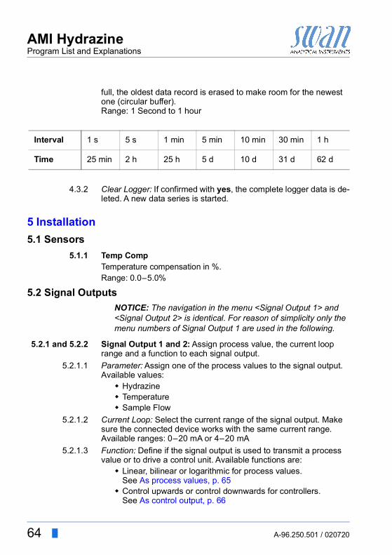
4.3 LoggerThe instrument is equipped with an internal logger. The logger data can be copied to a PC with an USB stick if option USB interface is installed.The logger can save approx. 1500 data records. The Records con-sists of: Date, time, alarms, measuring value, measuring value un-compensated, case temperature, flow.
4.3.1 Log Interval: Select a convenient log interval. Consult the table be-low to estimate the max logging time. When the logging buffer is
3.4.13.4.23.4.33.4.43.4.5
Alarm Relay:Relay 1:Relay 2Signal Output 1:Signal Output 2
Active or inactiveActive or inactiveActive or inactiveActual current in mAActual current in mA
64 A-96.250.501 / 020720
AMI HydrazineProgram List and Explanations
full, the oldest data record is erased to make room for the newest one (circular buffer).Range: 1 Second to 1 hour
4.3.2 Clear Logger: If confirmed with yes, the complete logger data is de-leted. A new data series is started.
5 Installation5.1 Sensors
5.1.1 Temp CompTemperature compensation in %. Range: 0.0–5.0%
5.2 Signal OutputsNOTICE: The navigation in the menu <Signal Output 1> and <Signal Output 2> is identical. For reason of simplicity only the menu numbers of Signal Output 1 are used in the following.
5.2.1 and 5.2.2 Signal Output 1 and 2: Assign process value, the current loop range and a function to each signal output.
5.2.1.1 Parameter: Assign one of the process values to the signal output.Available values: Hydrazine Temperature Sample Flow
5.2.1.2 Current Loop: Select the current range of the signal output. Make sure the connected device works with the same current range.Available ranges: 0–20 mA or 4–20 mA
5.2.1.3 Function: Define if the signal output is used to transmit a process value or to drive a control unit. Available functions are: Linear, bilinear or logarithmic for process values.
See As process values, p. 65 Control upwards or control downwards for controllers.
See As control output, p. 66
Interval 1 s 5 s 1 min 5 min 10 min 30 min 1 h
Time 25 min 2 h 25 h 5 d 10 d 31 d 62 d
AMI HydrazineProgram List and Explanations
A-96.250.501 / 020720 65
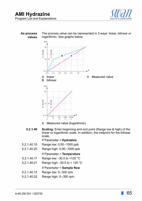
As processvalues
The process value can be represented in 3 ways: linear, bilinear or logarithmic. See graphs below.
5.2.1.40 Scaling: Enter beginning and end point (Range low & high) of the linear or logarithmic scale. In addition, the midpoint for the bilinear scale.If Parameter = Hydrazine
5.2.1.40.10 Range low: 0.00–1000 ppb5.2.1.40.20 Range high: 0.00–1000 ppb
If Parameter = Temperature5.2.1.40.11 Range low: -30.0 to +120 °C5.2.1.40.21 Range high: -30.0 to + 120 °C
If Parameter = Sample flow5.2.1.40.12 Range low: 0–300 rpm5.2.1.40.22 Range high: 0–300 rpm
AB
linearbilinear
X Measured value
X Measured value (logarithmic)
20
0.0 0.1 0.2 0.3 0.4 0.5
10 12
(0 -
20 [m
A])
0 / 4
(4 -
20 [m
A])
[mA]
X
AB
20
10 1 2 3 4
10 100 1’000 10’000
10 12
(0 -
20 [m
A])
0 / 442 6
(4 -
20 [m
A])
[mA]
X

66 A-96.250.501 / 020720
AMI HydrazineProgram List and Explanations
As controloutput
Signal outputs can be used for driving control units. We distinguish different kinds of controls: P-controller: The controller action is proportional to the devia-
tion from the setpoint. The controller is characterized by the P-Band. In the steady-state, the setpoint will never be reached. The deviation is called steady-state error.Parameters: setpoint, P-Band
PI-controller: The combination of a P-controller with an I-con-troller will minimize the steady-state error. If the reset time is set to zero, the I-controller is switched off.Parameters: setpoint, P-Band, reset time.
PD-controller: The combination of a P-controller with a D-controller will minimize the response time to a fast change of the process value. If the derivative time is set to zero, the D-controller is switched off.Parameters: setpoint, P-Band, derivative time.
PID-controller: The combination of a P-, an I - and a D-con-troller allows a proper control of the process.Parameters: setpoint, P-Band, reset time, derivative time.
Ziegler-Nichols method for the optimization of a PID controller:Parameters: Setpoint, P-Band, Reset time, Derivative time
The point of intersection of the tangent with the respective axis will result in the parameters a and L.Consult the manual of the control unit for connecting and program-ming details. Choose control upwards or downwards.
ABX
Response to maximum control outputTangent on the inflection pointTime
XpTnTv
= 1.2/a= 2L= L/2
X
Y
B A
L
a

AMI HydrazineProgram List and Explanations
A-96.250.501 / 020720 67
If Control upwards or Control downwards is activeSetpoint: User-defined process value (Measured value or flow)P-Band: Range below (upwards control) or above (downwards control) the set-point, within the dosing intensity is reduced from 100% to 0% to reach the set-point without overshooting.
5.2.1.43 Control Parameters: if Parameter = Hydrazine5.2.1.43.10 Setpoint
Range: 0.00–1000 ppb5.2.1.43.20 P-Band
Range:0.00–1000 ppb
5.2.1.43 Control Parameters: if Parameter = Temperature5.2.1.43.11 Setpoint
Range: -30 to +120 °C5.2.1.43.21 P-Band
Range: 0 to +100 °C
5.2.1.43 Control Parameters: if Parameter = Sample Flow5.2.1.43.12 Setpoint
Range: 0–300 rpm5.2.1.43.22 P-Band
Range: 0–300 rpm5.2.1.43.3 Reset time: The reset time is the time till the step response of a sin-
gle I-controller will reach the same value as it will be suddenly reached by a P-controller.Range: 0–9’000 sec
5.2.1.43.4 Derivative time: The derivative time is the time till the ramp re-sponse of a single P-controller will reach the same value as it will be suddenly reached by a D-controller.Range: 0–9’000 sec
5.2.1.43.5 Control timeout: If a controller action (dosing intensity) is constantly over 90% during a defined period of time and the process value does not come closer to the setpoint, the dosing process will be stopped for safety reasons.Range: 0–720 min
5.3 Relay Contacts5.3.1 Alarm Relay: The alarm relay is used as cumulative error indicator.
Under normal operating conditions the contact is active.The contact is inactive at: Power loss

68 A-96.250.501 / 020720
AMI HydrazineProgram List and Explanations
Detection of system faults like defective sensors or electronic parts
High case temperature Process values out of programmed ranges.
Program alarm levels for the following parameters: Alarm Hydrazine Sample Flow Sample Temp. Case Temp. high Case Temp. low
5.3.1.1 Alarm Hydrazine5.3.1.1.1 Alarm High: If the measured value rises above the alarm high val-
ue, the alarm relay is activated and E001, is displayed in the mes-sage list. Range: 0.00–1000 ppb
5.3.1.1.25 Alarm Low: If the measured value falls below the alarm low value, the alarm relay is activated and E002 is displayed in the message list.Range: 0.00–1000 ppb
5.3.1.1.35 Hysteresis: Within the hyst. range, the relay does not switch. This prevents damage of relays contacts when the measured value fluc-tuates around the alarm value.Range. 0.00–1000 ppb
5.3.1.1.45 Delay: Duration, the activation of the alarm relay is retarded after the measuring value has risen above/fallen below the programmed alarm.Range: 0–28‘800 Sec
5.3.1.2 Sample Flow: Define at which sample flow a flow alarm should be issued.
5.3.1.2.1 Flow Alarm: Program if the alarm relay should be activated if there is a flow alarm. Choose between yes or no. The flow alarm will al-ways be indicated in the display, pending error list, saved in the message list and the logger.Available values: Yes or no
NOTICE: Sufficient flow is essential for a correct measurement.We recommend to program yes.
5.3.1.2.2 Alarm High: If the measuring values rises above the programmed value E009 will be issued.Range: 150–300 rpm

AMI HydrazineProgram List and Explanations
A-96.250.501 / 020720 69
5.3.1.2.35 Alarm Low: If the measuring values falls below the programmed value E010 will be issued.Range: 150–300 rpm
5.3.1.3 Sample Temp.: Define at which sample temperature an alarm should be issued.
5.3.1.3.1 Alarm High: If the measured value rises above the alarm high val-ue, the alarm relay is activated and E007 is issued.Range: 30–70 °C
5.3.1.3.25 Alarm Low: If the measured value rises above the alarm high value, the alarm relay is activated and E008 is issued.Range: 0–20 °C
5.3.1.4 Case Temp. high: Set the alarm high value for temperature of elec-tronics housing. If the value rises above the programmed value E013 is issued.Range: 30–75 °C
5.3.1.5 Case Temp. low: Set the alarm low value for temperature of elec-tronics housing. If the value falls below the programmed value E014 is issued.Range: -10 to + 20 °C
5.3.2 and 5.3.3 Relay 1 and 2: The contacts can be set as normally open or nor-mally closed with a jumper. See Relay Contacts 1 and 2, p. 23. The function of relay contacts 1 or 2 are defined by the user.
NOTICE: The navigation in the menu <Relay 1> and <Relay 2> is identical. For reason of simplicity only the menu numbers of Relay 1 are used in the following.
1 First select the functions as:- Limit upper/lower- Control upwards/downwards- Timer- Fieldbus
2 Then enter the necessary data depending on the selected func-tion.
When the relays are used as upper or lower limit switches, program the following:
5.3.2.20 Parameter: select a process value5.3.2.300 Setpoint: If the measured value rises above respectively falls below
the set-point, the relay is activated.
5.3.2.1 Function = Limit upper/lower:

70 A-96.250.501 / 020720
AMI HydrazineProgram List and Explanations
5.3.2.400 Hysteresis: within the hysteresis range, the relay does not switch. This prevents damage of relay contacts when the measured value fluctuates around the alarm value.
5.3.2.50 Delay: Duration, the activation of the alarm relay is retarded after the measuring value has risen above/fallen below the programmed alarm.Range. 0–600 Sec
The relays may be used to drive control units such as solenoid valves, membrane dosing pumps or motor valves. When driving a motor valve both relays are needed, relay 1 to open and relay 2 to close the valve.
5.3.2.22 Parameter: select a process value: Hydrazine Temperature Sample flow
5.3.2.32 SettingsChoose the respective actuator: Time proportional Frequency Motor valve
Examples of metering devices that are driven time proportional are solenoid valves, peristaltic pumps.Dosing is controlled by the operating time.
Parameter Range Hydrazine 0.00–1000 ppbTemperature -30 to +120 °CSample flow 0–300 rpm
Parameter Range Hydrazine 0.00–1000 ppbTemperature 0 to +100 °CSample flow 0–300 rpm
5.3.2.1 Function = Control upwards/downwards:
Actuator = Time proportional

AMI HydrazineProgram List and Explanations
A-96.250.501 / 020720 71
5.3.2.32.20 Cycle time: duration of one control cycle (on/off change).Range: 0–600 sec.
5.3.2.32.30 Response time: Minimal time the metering device needs to react. Range: 0–240 sec.
5.3.2.32.4 Control Parameters: Range for each Parameter same as 5.2.1.43, p. 67
Examples of metering devices that are pulse frequency driven are the classic membrane pumps with a potential free triggering input. Dosing is controlled by the repetition speed of dosing shots.
5.3.2.32.21 Pulse frequency: Max. pulses per minute the device is able to re-spond to. Range: 20–300/min.
5.3.2.32.31 Control Parameters:Range for each Parameter same as 5.2.1.43, p. 67
Dosing is controlled by the position of a motor driven mixing valve.5.3.2.32.22 Run time: Time needed to open a completely closed valve
Range: 5–300 Sec.5.3.2.32.32 Neutral zone: Minimal response time in % of the runtime. If the re-
quested dosing output is smaller than the response time, no change will take place.Range: 1–20 %
5.3.2.32.4 Control Parameters:Range for each Parameter same as 5.2.1.43, p. 67
The relay will be active repetitively depending on the programmed time scheme.
5.3.2.24 Mode: Operating mode
5.3.2.340 Interval: The interval can be programmed within a rangeof 1–1440 min.
Actuator = Frequency
Actuator = Motor valve
5.3.2.1 Function = Timer
Modeintervaldailyweekly
5.3.2.24 Interval

72 A-96.250.501 / 020720
AMI HydrazineProgram List and Explanations
5.3.2.44 Run Time: Enter the time the relay stays active.Range: 5–32400 sec.
5.3.2.54 Delay: during run time plus the delay time the signal and control outputs are held in the operating mode programmed below.Range: 0–6’000 sec.
5.3.2.6 Signal Outputs: Select operating mode of the signal output:
5.3.2.7 Output/Control: Select operating mode of the controller output:
The relay contact can be activated daily, at any time of a day.5.3.2.341 Start time: to set the start time proceed as follows:
1 Press [Enter], to set the hours.2 Set the hour with the [ ] or [ ] keys.3 Press [Enter], to set the minutes.4 Set the minutes with the [ ] or [ ] keys.5 Press [Enter], to set the seconds.6 Set the seconds with the [ ] or [ ] keys.
Range: 00:00:00–23:59:595.3.2.44 Run Time: see Interval5.3.2.54 Delay: see Interval5.3.2.6 Signal Outputs: see Interval5.3.2.7 Output/Control: see Interval
The relay contact can be activated at one or several days, of a week. The daily starting time is valid for all days.
Cont.: Signal outputs continue to issue the measured value.Hold: Signal outputs hold the last valid measured value.
Measurement is interrupted. Errors, except fatal errors, are not issued.
Off: Signal outputs are switched off (set to 0 or 4 mA).Errors, except fatal errors, are not issued.
Cont.: Controller continues normally.Hold: Controller continues based on the last valid value.Off: Controller is switched off.
5.3.2.24 daily
5.3.2.24 weekly

AMI HydrazineProgram List and Explanations
A-96.250.501 / 020720 73
5.3.2.342 Calendar:5.3.2.342.1 Start time: The programmed start time is valid for each of the pro-
grammed days. To set the start time see 5.3.2.341, p. 72.Range: 00:00:00–23:59:59
5.3.2.342.2 Monday: Possible settings, on or offto
5.3.2.342.8 Sunday: Possible settings, on or off5.3.2.44 Run Time: see Interval5.3.2.54 Delay: see Interval5.3.2.6 Signal Outputs: see Interval5.3.2.7 Output/Control: see Interval
The relay will be switched via the Profibus input. No further param-eters are needed.
5.3.4 Input: The functions of the relays and signal outputs can be de-fined depending on the position of the input contact, i.e. no function, closed or open.
NOTICE: If the option 2nd Sample Stream is connected to theAMI Hydrazine and <Channel Selection> is set to <External>, the Input will be set to “Active = no” and no further settings are possible.
5.3.4.1 Active: Define when the input should be active:
5.3.4.2 Signal Outputs: Select the operation mode of the signal outputs when the relay is active:
5.3.2.1 Function = Fieldbus
No: Input is never active.When closed: Input is active if the input relay is closedWhen open: Input is active if the input relay is open
Continuous: Signal outputs continue to issue the measured value.Hold: Signal outputs issue the last valid measured value.
Measurement is interrupted. Errors, except fatal errors, are not issued.
Off: Set to 0 or 4 mA respectively. Errors, except fatal errors, are not issued.

74 A-96.250.501 / 020720
AMI HydrazineProgram List and Explanations
5.3.4.3 Output/Control: (relay or signal output):
5.3.4.4 Fault:
5.3.4.5 Delay: Time which the instrument waits, after the input is deactivat-ed, before returning to normal operation.Range: 0–6‘000 Sec
5.4 Miscellaneous5.4.1 Language: Set the desired language.
5.4.2 Set defaults: Reset the instrument to factory default values in three different ways:
Calibration: Sets calibration values back to default. All other values are kept in memory.
In parts: Communication parameters are kept in memory. All other values are set back to default values.
Completely: Sets back all values including communication parameters.
Continuous: Controller continues normally.Hold: Controller continues on the last valid value.Off: Controller is switched off.
No: No message is issued in pending error list and the alarm relay does not close when input is active. Message E024 is stored in the message list.
Yes: Message E024 is issued and stored in the mes-sage list. The Alarm relay closes when input is active.
LanguageGermanEnglishFrenchSpanish
Set defaultsnoCalibrationIn partsCompletely

AMI HydrazineProgram List and Explanations
A-96.250.501 / 020720 75
5.4.3 Load Firmware: Firmware updates should be done by instructed service personnel only.
5.4.4 Password: Select a password different from 0000 to prevent unau-thorized access to the following menus:
5.4.4.1 Messages5.4.4.2 Maintenance5.4.4.3 Operation5.4.4.4 Installation.
Each menu may be protected by a different password.If you forgot the passwords, contact the closest SWAN representative.
5.4.5 Sample ID: Identify the process value with any meaning full text, such as KKS number.
5.4.6 Line Break Detection: Define if message E028 should be issued in case of a line break on signal output 1 or 2.Choose between <Yes> or <No>.
5.5 InterfaceSelect one of the following communication protocols. Depending on your selection, different parameters must be defined.
Load Firmwarenoyes
5.5.1 Protocol: Profibus5.5.20 Device address: Range: 0–1265.5.30 ID-Nr.: Range: Analyzer; Manufacturer; Multivariable5.5.40 Local operation: Range: Enabled, Disabled
5.5.1 Protocol: Modbus RTU5.5.21 Device address: Range: 0–1265.5.31 Baud Rate: Range: 1200–115 200 Baud5.5.41 Parity: Range: none, even, odd
5.5.1 Protocol: USB-Stick:Only visible if an USB interface is installed. No further settings are possible.
5.5.1 Protocol: HARTDevice address: Range: 0–63
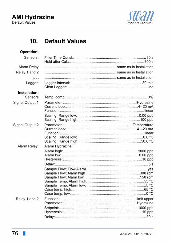
76 A-96.250.501 / 020720
AMI HydrazineDefault Values
10. Default ValuesOperation:
Sensors: Filter Time Const.:...................................................................... 30 sHold after Cal.:......................................................................... 300 s
Alarm Relay ...................................................................... same as in InstallationRelay 1 and 2 ...................................................................... same as in Installation
Input ...................................................................... same as in InstallationLogger: Logger Interval:..................................................................... 30 min
Clear Logger: ................................................................................noInstallation:
Sensors Temp. comp.: .............................................................................. 3%Signal Output 1 Parameter: ........................................................................Hydrazine
Current loop: ......................................................................4–20 mAFunction: .................................................................................. linearScaling: Range low: ............................................................0.00 ppbScaling: Range high:............................................................100 ppb
Signal Output 2 Parameter: ....................................................................TemperatureCurrent loop: .....................................................................4 –20 mAFunction: .................................................................................. linearScaling: Range low: ................................................................0.0 °CScaling: Range high:.............................................................50.0 °C
Alarm Relay: Alarm Hydrazine:Alarm high:.........................................................................1000 ppbAlarm low: ...........................................................................0.00 ppbHysteresis: .............................................................................10 ppbDelay:........................................................................................... 5 sSample Flow; Flow Alarm ........................................................... yesSample Flow; Alarm high .....................................................300 rpmSample Flow; Alarm low ......................................................150 rpmSample Temp; Alarm high: .......................................................55 °CSample Temp; Alarm low: ..........................................................5 °CCase temp. high:......................................................................65 °CCase temp. low: .........................................................................0 °C
Relay 1 and 2 Function: .......................................................................... limit upperParameter: ........................................................................HydrazineSetpoint:.............................................................................1000 ppbHysteresis: .............................................................................10 ppbDelay:......................................................................................... 30 s

AMI HydrazineDefault Values
A-96.250.501 / 020720 77
If Function = Control upw. or dnw:Parameter:.......................................................................HydrazineSettings: Actuator: .......................................................... Frequency
Settings: Pulse Frequency: ..............................................120/minSettings: Control Parameters: Setpoint:......................... 1000 ppbSettings: Control Parameters: P-band: .............................. 10 ppb
Parameter:...................................................................TemperatureSettings: Actuator: .......................................................... Frequency
Settings: Pulse Frequency: ..............................................120/minSettings: Control Parameters: Setpoint:............................... 30 °CSettings: Control Parameters: P-band: .................................. 1 °C
Parameter:................................................................... Sample flowSettings: Actuator: .......................................................... Frequency
Settings: Pulse Frequency: ..............................................120/minSettings: Control Parameters: Setpoint:...........................300 rpmSettings: Control Parameters: P-band: ..............................10 rpm
Common SettingsSettings: Control Parameters: Reset time:............................... 0 sSettings: Control Parameters: Derivative Time: ....................... 0 sSettings: Control Parameters: Control Timeout:................... 0 min
Settings: Actuator: ................................................ Time proportionalCycle time: ............................................................................ 60 sResponse time: ..................................................................... 10 s
Settings: Actuator ......................................................... Motor valveRun time: ............................................................................... 60 sNeutral zone: ...........................................................................5%
If Function = Timer:Mode:.................................................................................... Interval
Interval: ................................................................................ 1 minMode: ........................................................................................daily
Start time:........................................................................ 00.00.00Mode:..................................................................................... weekly
Calendar; Start time: ....................................................... 00.00.00Calendar; Monday to Sunday:.................................................. Off
Run time: ................................................................................... 10 sDelay: .......................................................................................... 5 sSignal output:............................................................................. contOutput/Control: .......................................................................... cont
Input: Active............................................................................ when closedSignal Outputs ........................................................................... hold

78 A-96.250.501 / 020720
AMI HydrazineDefault Values
Output/Control ..............................................................................offFault..............................................................................................noDelay.......................................................................................... 10 s
Miscellaneous Language:............................................................................. EnglishSet default:....................................................................................noLoad firmware: ..............................................................................noPassword: ........................................................... for all modes 0000Sample ID: ....................................................................... - - - - - - - -Line break detection .....................................................................no

A-96.250.501 / 020720 79
AMI HydrazineIndex
11. IndexAAlarm Hydrazine . . . . . . . 68Alarm Relay . . . . . . . . 8, 22
CCable thicknesses . . . . . . 18Cal. History . . . . . . . . . . 61Calendar . . . . . . . . . . . 73Changing values. . . . . . . 34Checklist . . . . . . . . . . . 14Cleaning
Flow Cell . . . . . . . . 41Hydrazine sensor. . . . 38Reference Electrode . . 40
ConnectSample inlet. . . . . . . 15Waste . . . . . . . . . . 15
Control Parameters . . . . . 67
DDefault Values . . . . . . . . 76
EEPDM seal . . . . . . . . . . 44Error List . . . . . . . . . . . 50
FFlow . . . . . . . . . . . . . . 41Fluidics . . . . . . . . . . . . . 9Function
Control upwards / downwards 70Limit upper / lower . . . 69Timer. . . . . . . . . . . 71
HHART . . . . . . . . . . . . . 27
IInput . . . . . . . . . . 8, 22, 73
Instrument Overview . . . . 13Interface . . . . . . . . . . . . 8
HART . . . . . . . . . . 27Modbus . . . . . . . . . 26Profibus . . . . . . . . . 26USB . . . . . . . . . . . 27
LLogger . . . . . . . . . . . . 63Longer Stop of Operation. . 49
MModbus . . . . . . . . . . . . 26Mounting requirements . . . 15
OOn-site requirements . . . . 11
PPower Supply . . . . . . 11, 21Profibus . . . . . . . . . . . . 27
RRelays. . . . . . . . . . . . 8, 23
SSample Flow . . . . . . . 29, 68Sample Temp. . . . . . . . . 69Setup . . . . . . . . . . . . . 28Signal Outputs . . . . 8, 25, 64Simulation . . . . . . . . . . 62Software . . . . . . . . . . . 33System, Description of . . . . 8
TTechnical Data. . . . . . . . 13Terminals . . . . 20, 22–23, 26
UUSB Interface . . . . . . . . 27
80 A-96.250.501 / 020720
AMI HydrazineNotes
12. Notes

AMI HydrazineNotes
A-96.250.501 / 020720 81

82 A-96.250.501 / 020720
AMI Hydrazine
SWANis represented worldwide by subsidiary companies and distributors.
cooperates with independent representatives all over the world.
SWAN Products
Analytical Instruments for:
High Purity Water
Feedwater, Steam and Condensate
Potable Water
Pool and Sanitary Water
Cooling Water
Waste Water and Effluents
Made in Switzerland