Medium External Fixator—Tibial Shaft Box Frame. For small
12
Medium External Fixator — Tibial Shaft Box Frame. For small-statured adults and pediatric patients, using outrigger posts. Technique Guide Part of the Medium External Fixation System
Transcript of Medium External Fixator—Tibial Shaft Box Frame. For small
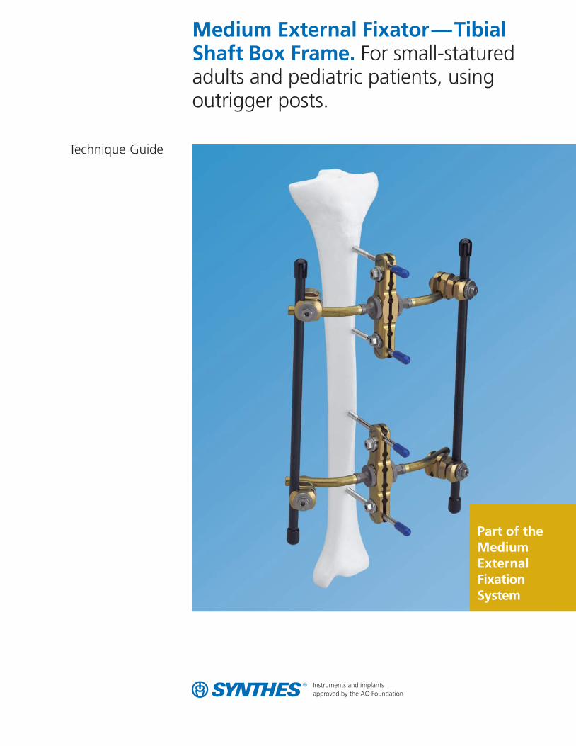
Medium External Fixator—TibialShaft Box Frame. For small-staturedadults and pediatric patients, usingoutrigger posts.
Technique Guide
Part of theMediumExternalFixationSystem

Synthes Medium External Fixator—Tibial Shaft Box Frame Technique Guide
MRI Information
Synthes Medium External Fixation devices are labeled MR Conditional according to the terminology specified inASTM F2503-05, Standard Practice for Marking Medical Devices and Other Items for Safety in the Magnetic Resonance Environment.
Nonclinical testing demonstrated that, when used in the specific configurations stated in Synthes labeling, SynthesMedium External Fixation devices are MR Conditional. Representative Synthes Medium External Fixation devicesused in a typical construct include clamps, rods and variousattachments. A patient with a Synthes Medium ExternalFixation frame may be scanned safely after placement of theframe under the following conditions.
Static magnetic field of 1.5 Tesla when the fixation frameis positioned:– 7 cm or less from within the outside edge of the bore of
the MRI at Normal Operating Mode or;
– Completely outside of the MRI bore in First Level Controlled Mode
Static magnetic field of 3.0 Tesla when the fixation frameis positioned:– 7 cm or less from within the outside edge of the bore of
the MRI at Normal Operating Mode or;
– Completely outside of the MRI bore in First Level Controlled Mode
Highest spatial gradient magnetic field of 900 Gauss /cmor less
Maximum MR system reported whole body averagedspecific absorption rate (SAR) of 2 W/kg for the NormalOperatinig Mode and 4 W/kg for the First Level ControlledMode for 15 minutes of scanning
Use only whole body RF transmit coil, no other transmitcoils are allowed, local receive only coils are allowed.
Note: In nonclinical testing, the Synthes external fixationframe was tested in several different configurations. Thistesting was conducted with the construct positioned 7 cmfrom within the outside edge of the MRI bore.– The results showed a maximum observed heating for a
wrist fixation frame of 6ºC for 1.5 T and less than 1ºC for3.0 T with a machine reported whole body averaged SARof 2 W/kg.
Patients may be safely scanned in the MRI chamber at theabove conditions. Under such conditions, the maximal expected temperature rise is less than 6ºC. Because higher in vivo heating cannot be excluded, close patient monitoringand communication with the patient during the scan is required. Immediately abort the scan if the patient reportsburning sensation or pain. To minimize heating, the scantime should be as short as possible, the SAR as low as possible, and the device should be as far as possible from the edge of the bore. Temperature rise values obtained werebased upon a scan time of 15 minutes.
The above field conditions should be compared with those of the user’s MR system, to determine if the item can safelybe brought into the user’s MR environment. If placed in thebore of the MR scanner during scanning, Synthes MR Conditional external fixation devices may have the potentialto cause artifact in the diagnostic imaging.
All components of Synthes external fixation frames must beidentified as MR Conditional prior to being placed in or nearan MR environment.
Artifact informationMR image quality may be compromised if the area of interest is in the same area or relatively close to the positionof the Synthes Medium External Fixation construct, and it may be necessary to optimize MR imaging parameters, to compensate for the presence of the fixation frame.
Representative devices used to assemble a typical SynthesMedium External Fixation frame have been evaluated in the MRI chamber and worst-case artifact information isprovided below. Overall, artifacts created by Synthes Medium External Fixation devices may present issues if theMR imaging area of interest is in or near the area where the fixation frame is located.– For FFE sequence: Scan duration: 3 min, TR 100 ms,
TE 15 ms, flip angle 15º and SE sequence: Scan duration: 4 min, TR 500 ms, TE 20 ms, flip angle 70º radio echo sequence, worst-case artifact will extend approximately 10 cm from the device.
Warning– Do not place any radio frequency (RF) transmit coils
over the external fixation frame.
Synthes 1
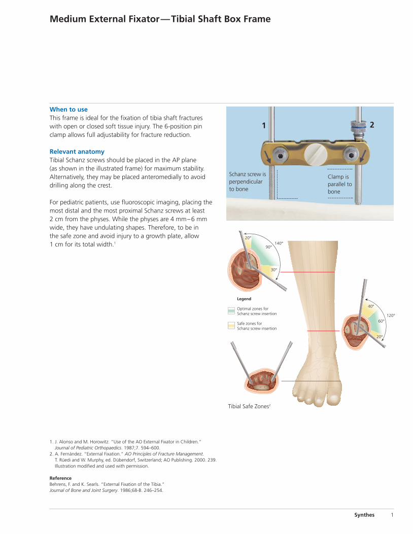
When to use This frame is ideal for the fixation of tibia shaft fractures with open or closed soft tissue injury. The 6-position pinclamp allows full adjustability for fracture reduction.
Relevant anatomyTibial Schanz screws should be placed in the AP plane (as shown in the illustrated frame) for maximum stability.Alternatively, they may be placed anteromedially to avoiddrilling along the crest.
For pediatric patients, use fluoroscopic imaging, placing themost distal and the most proximal Schanz screws at least 2 cm from the physes. While the physes are 4 mm–6 mmwide, they have undulating shapes. Therefore, to be in the safe zone and avoid injury to a growth plate, allow 1 cm for its total width.1
1. J. Alonso and M. Horowitz. “Use of the AO External Fixator in Children.” Journal of Pediatric Orthopaedics. 1987;7. 594–600.
2. A. Fernández. “External Fixation.” AO Principles of Fracture Management.T. Rüedi and W. Murphy, ed. Dübendorf, Switzerland; AO Publishing. 2000. 239.Illustration modified and used with permission.
ReferenceBehrens, F. and K. Searls. “External Fixation of the Tibia.” Journal of Bone and Joint Surgery. 1986;68-B. 246–254.
Medium External Fixator—Tibial Shaft Box Frame
1 2
Clamp isparallel tobone
Schanz screw is perpendicularto bone
20°
90°
30°
40°
60°120°
20°
140°
Legend
Optimal zones forSchanz screw insertion
Safe zones forSchanz screw insertion
Tibial Safe Zones2

2 Synthes Medium External Fixator—Tibial Shaft Box Frame Technique Guide
Recommended Components for Basic Frame
Product Item Quantity Number Needed
390.029 30° Outrigger Post, 8 mm 2
390.027 Medium Pin Clamp, 6 position 2
390.031 Medium Combination Clamp 2
395.7xx 8.0 mm Carbon Fiber Rod 1
395.781 Protective Cap, for 28.0 mm Carbon Fiber Rods
394.993 Protective Cap, 4for 5.0 mm Fixation Pins
294.78x 5.0 mm Self-Drilling 4Schanz Screw

Technique Overview
1Insert Schanz screwsUse the 6-Position Drill Guide Handle (392.963) or pin clamp technique to ensure proper pin spacing.
2Attach pin clampTighten the vise plates.
3Attach outrigger postsThread the posts into the vise plates to a hard stop. For angled posts, turn the post counterclockwise to the desired orientation. Lock in position by turning the lock nut clockwise until tight.
4Attach carbon fiber rods Attach carbon fiber rods to the outrigger posts with combination clamps.
5Reduce fractureReduce the fracture and tighten all clamps.
Note: To increase stiffness, add a second rod to the frame by repeating Steps 3 and 4 on the opposite side of the pin clamps.
Synthes 3
1
2
1
1
1
2
3
3
45
4 Synthes Medium External Fixator—Tibial Shaft Box Frame Technique Guide
Medium Pin Clamp Technique
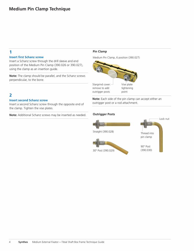
1Insert first Schanz screwInsert a Schanz screw through the drill sleeve and end position of the Medium Pin Clamp (390.026 or 390.027), using the clamp as an insertion guide.
Note: The clamp should be parallel, and the Schanz screwsperpendicular, to the bone.
2Insert second Schanz screwInsert a second Schanz screw through the opposite end ofthe clamp. Tighten the vise plates.
Note: Additional Schanz screws may be inserted as needed.
Stargrind cover: remove to add outrigger posts
30° Post (390.029)
90° Post (390.030)
Pin Clamp
Outrigger Posts
Lock nut
Medium Pin Clamp, 6 position (390.027)
Thread into pin clamp
Straight (390.028)
Vise platetighteningpoint
Note: Each side of the pin clamp can accept either an outrigger post or a rod attachment.
Synthes 5
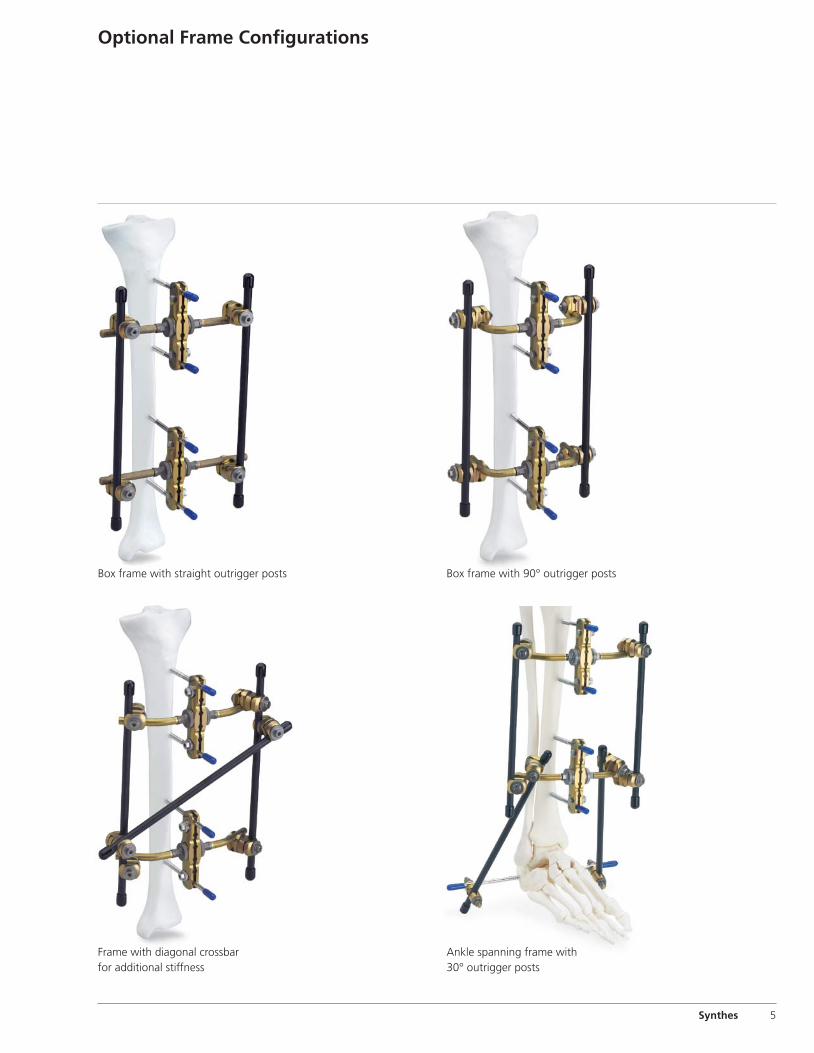
Optional Frame Configurations
Box frame with straight outrigger posts
Frame with diagonal crossbar for additional stiffness
Box frame with 90° outrigger posts
Ankle spanning frame with 30° outrigger posts

6 Synthes Medium External Fixator—Tibial Shaft Box Frame Technique Guide
Graphic Case690.450 Graphic Case, for Medium External Fixator
Implants in Set 01.302.602293.74 5.0 mm Steinmann Pin with Central Thread,
200 mm, 2 ea.
Self-Drilling Schanz Screws, 4 ea294.777 4.0 mm diameter, 125 mm.294.778 4.0 mm diameter, 150 mm294.785 5.0 mm diameter, 175 mm294.786 5.0 mm diameter, 200 mm
Implants in Set 01.302.604293.74 5.0 mm Steinmann Pin with Central Thread,
200 mm, 2 ea.
Titanium Self-Drilling Schanz Screws, 4 ea.494.777 4.0 mm diameter, 125 mm494.778 4.0 mm diameter, 150 mm494.785 5.0 mm diameter, 175 mm494.786 5.0 mm diameter, 200 mm
Instruments (for both sets)310.19 2.0 mm Drill Bit, quick coupling,
100 mm, 2 ea.310.37 3.5 mm Drill Bit, quick coupling,
195 mm, 2 ea.321.158 Combination Wrench, 8 mm width across flats392.955 4.0 mm/2.5 mm Drill Sleeve392.969 Combination T-Wrench, 8 mm 393.101 Drive Adaptor with quick coupling,
for 4.0 mm Schanz Screws 393.103 Drive Adaptor with quick coupling,
for 5.0 mm Schanz Screws393.105 Small Universal Chuck with T-Handle394.181 3.5 mm Trocar, short394.182 3.5 mm Trocar, long394.183 2.5 mm Trocar
Medium External Fixator Set with Self-Drilling Schanz Screws Stainless Steel (01.302.602) or Titanium (01.302.604)
Note: For additional information, please refer to package insert. For detailed cleaning and sterilization instructions, please refer tohttp://us.synthes.com/Medical+Community/Cleaning+and+Sterilization.htmor to the below listed inserts, which will be included in the shipping container:– Processing Synthes Reusable Medical Devices—Instruments, Instrument Trays
and Graphic Cases—DJ1305– Processing Non-sterile Synthes Implants—DJ1304

Also Available ImplantsSchanz Screws
294.43–.48 4.0 mm, spade point, 60 mm–150 mm294.52–.57 5.0 mm, blunted trocar point,
100 mm–250 mm294.71–.76 4.5 mm, blunted trocar point,
80 mm–200 mm
Self-Drilling Schanz Screws294.774–.779 4.0 mm, 60 mm–175 mm294.782–.788 5.0 mm, 100 mm–250 mm
Titanium Self-Drilling Schanz Screws494.774–.779 4.0 mm, 60 mm–175 mm494.782–.788 5.0 mm, 100 mm–250 mm
Steinmann Pins with Central Thread293.64 5.0 mm diameter, 150 mm293.69 5.0 mm diameter, 175 mm
Also Available Instruments03.302.001 Medium Open Compressor392.963 6-Position Drill Guide Handle
Also Available Fixation Material390.026 Medium Pin Clamp, 4 position390.027 Medium Pin Clamp, 6 position390.028 Straight Outrigger Post, 8 mm390.029 30° Outrigger Post, 8 mm390.030 90° Outrigger Post, 8 mm
Also Available Sets105.957 Power Drive Set150.16 ComPact Air Drive II Set
Also Available for Graphic Case690.350.13 Label Sheet Pack, for Schanz Screws
and Carbon Fiber Rods
Synthes 7
395.911 Drill Sleeve Handle395.912 5.0 mm/ 3.5 mm Drill Sleeve, short395.913 5.0 mm/3.5 mm Drill Sleeve, long395.921 6.0 mm/5.0 mm Threaded Drill Sleeve, short395.922 4.0 mm Threaded Drill Sleeve395.923 6.0 mm/5.0 mm Threaded Drill Sleeve, long
Fixation Material (for both sets)390.031 Medium Combination Clamp, 8 ea.390.032 Dynamization Clip, for Medium Combination
Clamp, 4 ea.390.033 Medium Multi-Pin Clamp, 4 position, 2 ea.390.034 Rod Attachment, for Medium Multi-Pin
Clamp, 4 ea.390.035 Medium Open Adjustable Clamp, 4 ea.390.036 Medium Multi-Pin Clamp, 6 position, 2 ea.390.037 8.0 mm/11.0 mm Combination Clamp, 2 ea.394.991 Protective Caps, for 4.0 mm Fixation Pins,
1 pkg. of 10394.993 Protective Caps, for 5.0 mm Fixation Pins,
1 pkg. of 10395.781 Protective Caps, for 8.0 mm Carbon Fiber
Rods, 4 pkgs. of 2
8.0 mm Carbon Fiber Rods395.779 160 mm, 2 ea.395.782 200 mm395.784 220 mm395.786 240 mm, 2 ea.395.788 280 mm, 2 ea.395.792 320 mm, 2 ea.395.796 360 mm, 2 ea.395.797 400 mm


Synthes (USA)1302 Wrights Lane EastWest Chester, PA 19380Telephone: (610) 719-5000To order: (800) 523-0322Fax: (610) 251-9056
Synthes (Canada) Ltd.2566 Meadowpine BoulevardMississauga, Ontario L5N 6P9Telephone: (905) 567-0440To order: (800) 668-1119Fax: (905) 567-3185
© 2005 Synthes, Inc. or its affiliates. All rights reserved. Synthes is a trademark of Synthes, Inc. or its affiliates. Printed in U.S.A. 5/11 J5839-D
www.synthes.com