
Medical Ultrasound Imaging - Universitetet i Oslo
62
UNIVERSITETET I OSLO Medical Ultrasound Imaging Sverre Holm Digital Signal Processing and I A l i G INSTITUTT FOR INFORMATIKK SH, 1 Image Analysis Group
Transcript of Medical Ultrasound Imaging - Universitetet i Oslo
UNIVERSITETET I OSLO
Medical Ultrasound Imagingg g
Sverre HolmDigital Signal Processing and
I A l i GINSTITUTT FOR INFORMATIKK SH, 1
Image Analysis Group
UNIVERSITETET I OSLO
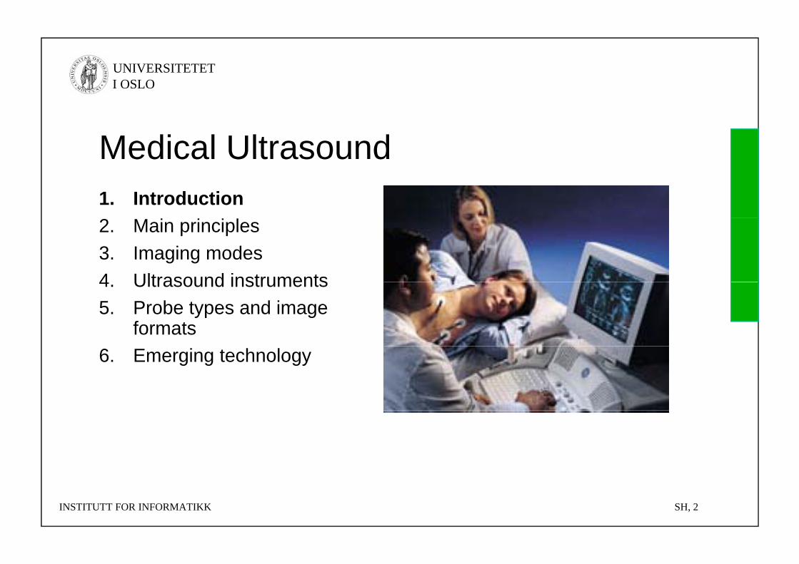
Medical UltrasoundMedical Ultrasound1. Introduction2. Main principles3. Imaging modes4 Ultrasound instruments4. Ultrasound instruments5. Probe types and image
formats6. Emerging technology
INSTITUTT FOR INFORMATIKK SH, 2
UNIVERSITETET I OSLO
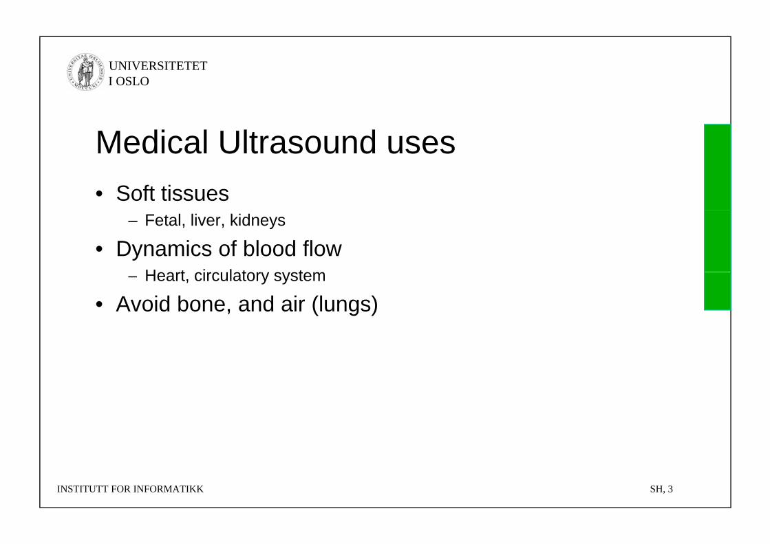
Medical Ultrasound usesMedical Ultrasound uses• Soft tissues
– Fetal, liver, kidneys
• Dynamics of blood flowH t i l t t– Heart, circulatory system
• Avoid bone, and air (lungs)
INSTITUTT FOR INFORMATIKK SH, 3
UNIVERSITETET I OSLO
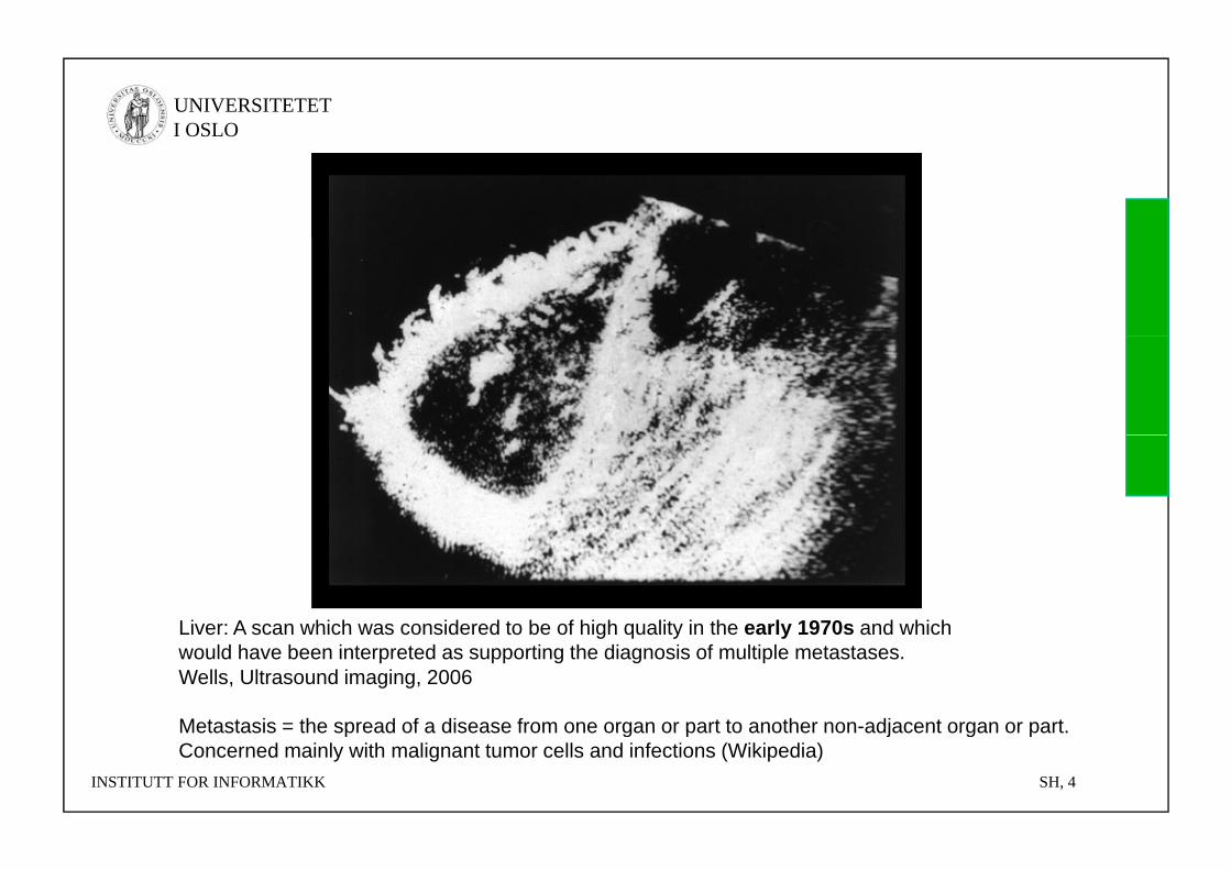
Liver: A scan which was considered to be of high quality in the early 1970s and whichLiver: A scan which was considered to be of high quality in the early 1970s and which would have been interpreted as supporting the diagnosis of multiple metastases.Wells, Ultrasound imaging, 2006
Metastasis = the spread of a disease from one organ or part to another non-adjacent organ or part.
INSTITUTT FOR INFORMATIKK SH, 4
Metastasis the spread of a disease from one organ or part to another non adjacent organ or part. Concerned mainly with malignant tumor cells and infections (Wikipedia)
UNIVERSITETET I OSLO
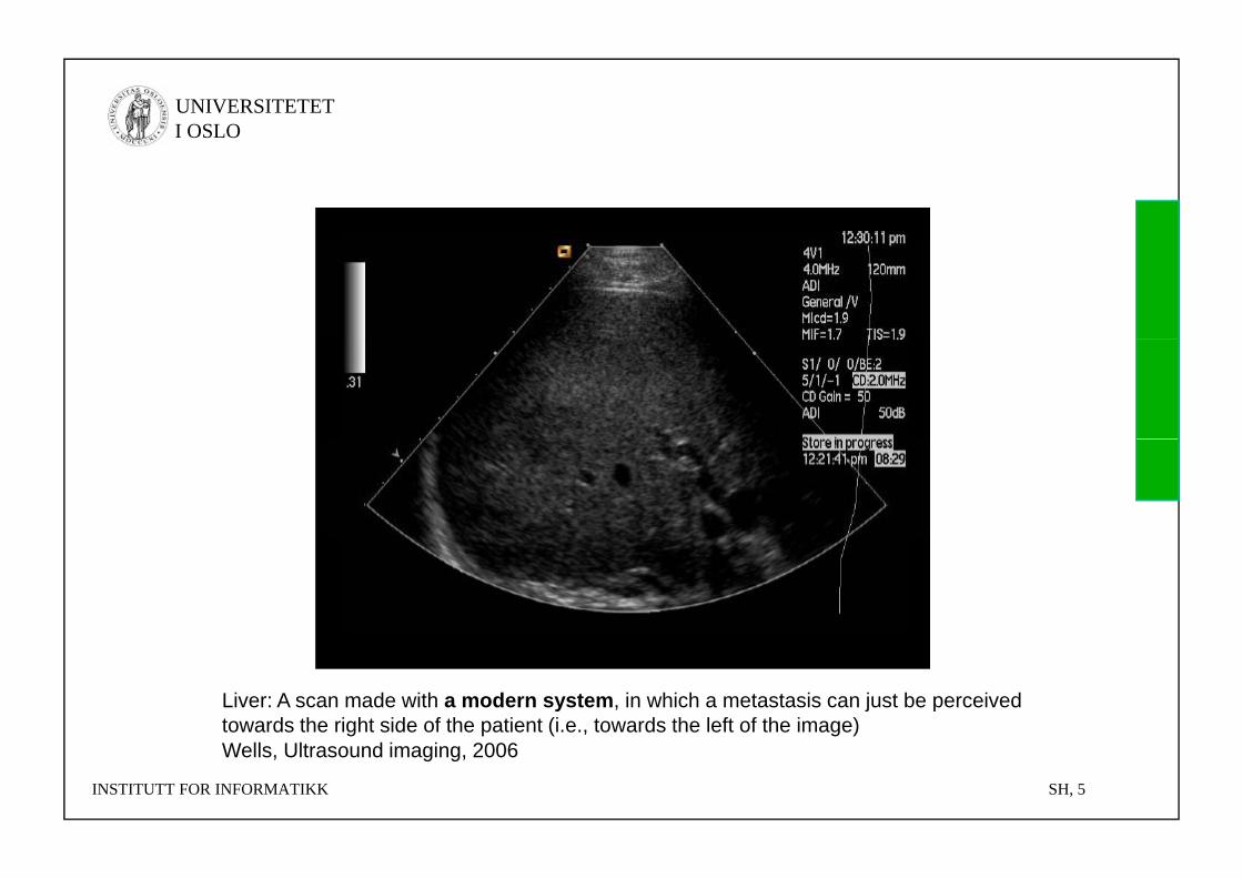
Liver: A scan made with a modern system, in which a metastasis can just be perceived towards the right side of the patient (i.e., towards the left of the image)
INSTITUTT FOR INFORMATIKK SH, 5
Wells, Ultrasound imaging, 2006
UNIVERSITETET I OSLO
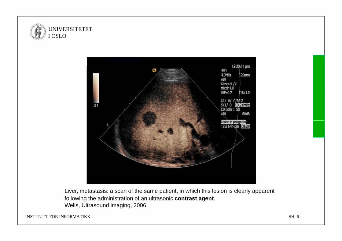
Liver, metastasis: a scan of the same patient, in which this lesion is clearly apparent following the administration of an ultrasonic contrast agent.
INSTITUTT FOR INFORMATIKK SH, 6
Wells, Ultrasound imaging, 2006
UNIVERSITETET I OSLO
Medical UltrasoundMedical Ultrasound• Continuously improving image quality =>
i d li i lincreased clinical usage• Relatively inexpensive compared to CT and MR
25% f ll i i i h it l i US– 25% of all imaging exams in hospitals is US
• Many clinical applications• Requires training and skill• Requires training and skill
INSTITUTT FOR INFORMATIKK SH, 7
UNIVERSITETET I OSLO
Norway: 30-40 years of developmentNorway: 30 40 years of development• 70’s: Started at NTNU, continued R&D since then
– L. Hatle og B. A. J. Angelsen, Doppler Ultrasound in Cardiology, Lea & Feibiger, Phil d l hi 1985
g g pp gy gPhiladelphia, 1985.
– B. A. J. Angelsen, Waves, Signals, and Signal Processing in MedicalUltrasonics, Vol I & Vol II, Institutt for fysiologi og biomedisinsk teknikk, NTNU, april 1996 +
– 2006-2014: Medical Imaging, Centre for Research-based Innovationg g,http://www.ntnu.no/milab
• 80’s: Vingmed Sound• 1998: GE Vingmed Ultrasound,
Now center of excellence for cardiology ultrasound in GE Healthcare– Now center of excellence for cardiology ultrasound in GE Healthcare – More than 2 billion NOK turnover controlled from Horten, Norway
• Other companies: – Medistim (quality control in surgery) on Oslo Stock Exchange
S d (i id d b d f i f lt d d MR)– Sonowand (image-guided surgery based on fusion of ultrasound and MR) – Neorad (ultrasound-guided injection of CT contrast agent in vein)– Auratech (High quality ultrasound engines/electronics)
INSTITUTT FOR INFORMATIKK SH, 8
UNIVERSITETET I OSLO
Medical UltrasoundMedical Ultrasound1. Introduction2. Main principles3. Imaging modes4 Ultrasound instruments4. Ultrasound instruments5. Probe types and image
formats6. Emerging technology
INSTITUTT FOR INFORMATIKK SH, 9
UNIVERSITETET I OSLO
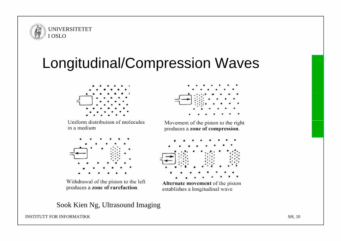
Longitudinal/Compression WavesLongitudinal/Compression Waves
S k Ki N Ul d I iINSTITUTT FOR INFORMATIKK SH, 10
Sook Kien Ng, Ultrasound Imaging
UNIVERSITETET I OSLO
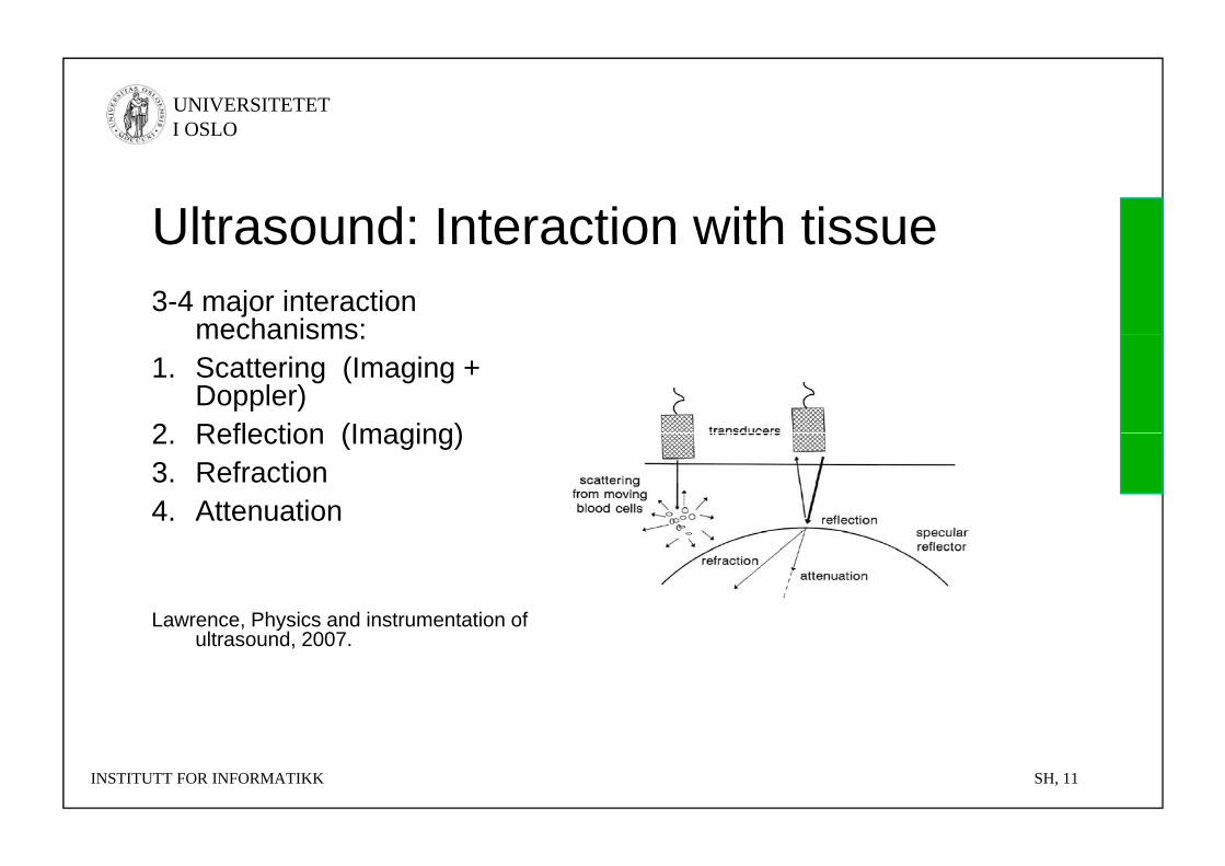
Ultrasound: Interaction with tissueUltrasound: Interaction with tissue3-4 major interaction
mechanisms:mechanisms:1. Scattering (Imaging +
Doppler)2 Reflection (Imaging)2. Reflection (Imaging)3. Refraction4. Attenuation
Lawrence, Physics and instrumentation of yultrasound, 2007.
INSTITUTT FOR INFORMATIKK SH, 11

UNIVERSITETET I OSLO
1 Scattering1. ScatteringA) Rough interfaces
B) Inhomogenous medium (causing speckle in images)
C) Particles (red blood cells)
Burns, Introduction to the physical principles of ultrasound imaging and d l 2005doppler, 2005
INSTITUTT FOR INFORMATIKK SH, 12
UNIVERSITETET I OSLO
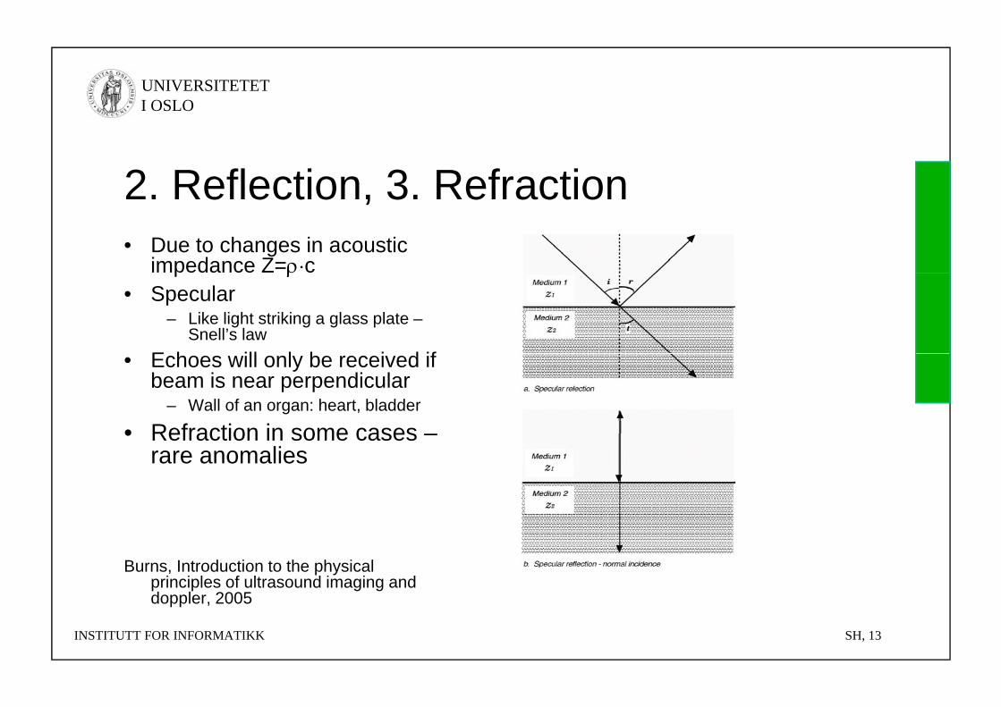
2 Reflection 3 Refraction2. Reflection, 3. Refraction• Due to changes in acoustic
impedance Z=·cp • Specular
– Like light striking a glass plate –Snell’s law
E h ill l b i d if• Echoes will only be received ifbeam is near perpendicular
– Wall of an organ: heart, bladder
• Refraction in some cases –• Refraction in some cases –rare anomalies
Burns, Introduction to the physical principles of ultrasound imaging and d l 2005
INSTITUTT FOR INFORMATIKK SH, 13
doppler, 2005
UNIVERSITETET I OSLO
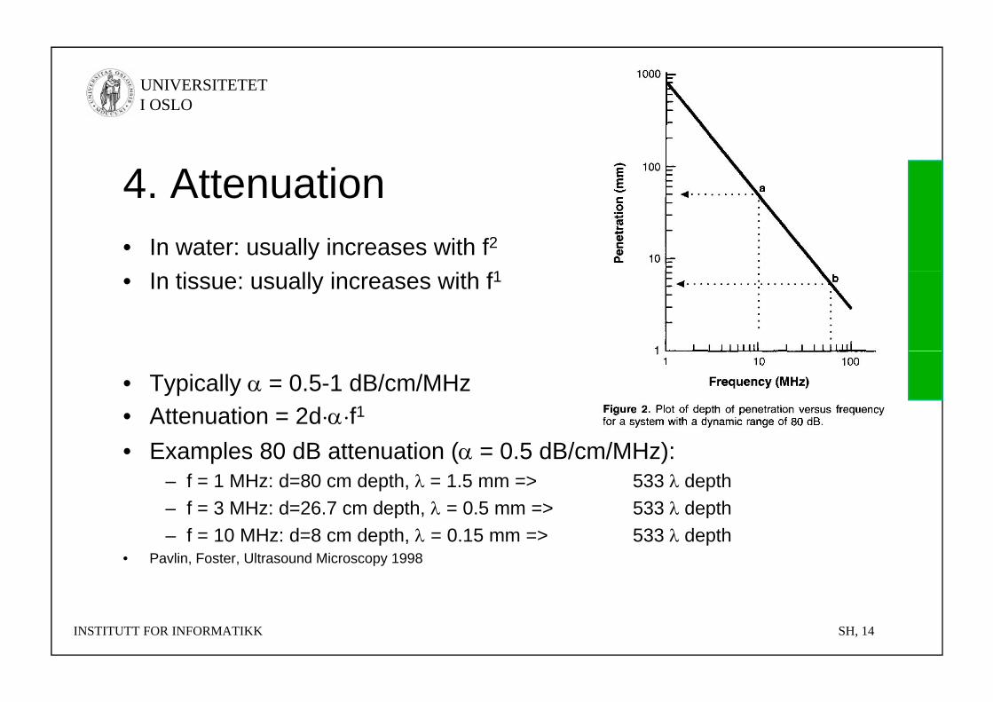
4 Attenuation4. Attenuation• In water: usually increases with f2
1• In tissue: usually increases with f1
• Typically = 0.5-1 dB/cm/MHz• Attenuation = 2d··f1
• Examples 80 dB attenuation ( = 0.5 dB/cm/MHz):– f = 1 MHz: d=80 cm depth, = 1.5 mm => 533 depth– f = 3 MHz: d=26 7 cm depth = 0 5 mm => 533 depthf = 3 MHz: d=26.7 cm depth, = 0.5 mm => 533 depth– f = 10 MHz: d=8 cm depth, = 0.15 mm => 533 depth
• Pavlin, Foster, Ultrasound Microscopy 1998
INSTITUTT FOR INFORMATIKK SH, 14
UNIVERSITETET I OSLO
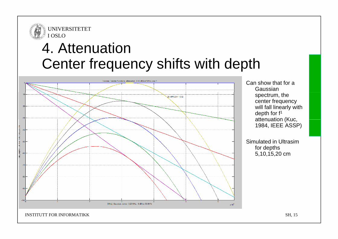
4. AttenuationCenter frequency shifts with depthCenter frequency shifts with depth
Can show that for a Gaussian spectrum, the center frequency will fall linearly with depth for f1attenuation (Kucattenuation (Kuc, 1984, IEEE ASSP)
Simulated in Ultrasim for depthsfor depths 5,10,15,20 cm
INSTITUTT FOR INFORMATIKK SH, 15
UNIVERSITETET I OSLO
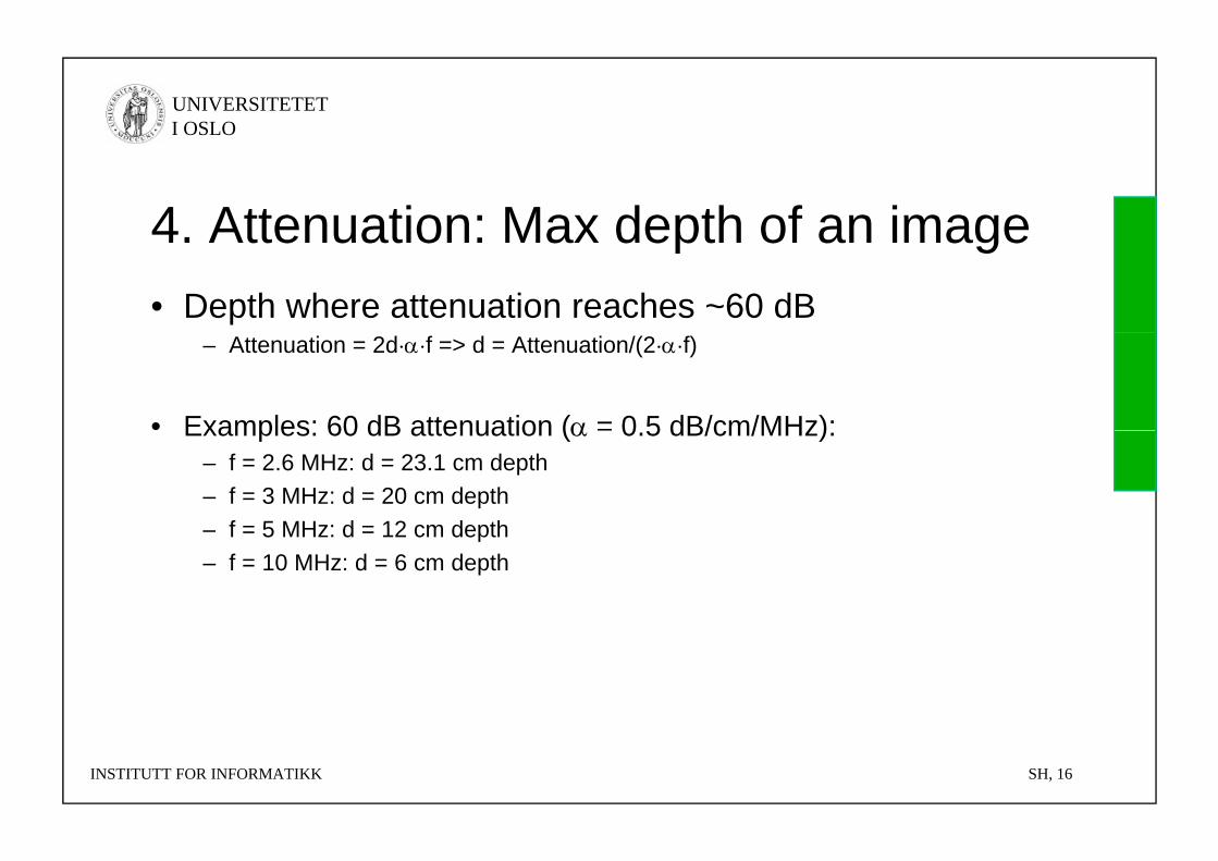
4 Attenuation: Max depth of an image4. Attenuation: Max depth of an image• Depth where attenuation reaches ~60 dB
– Attenuation = 2d··f => d = Attenuation/(2··f)
• Examples: 60 dB attenuation ( = 0 5 dB/cm/MHz):Examples: 60 dB attenuation ( 0.5 dB/cm/MHz):– f = 2.6 MHz: d = 23.1 cm depth– f = 3 MHz: d = 20 cm depth
f = 5 MHz: d = 12 cm depth– f = 5 MHz: d = 12 cm depth– f = 10 MHz: d = 6 cm depth
INSTITUTT FOR INFORMATIKK SH, 16
UNIVERSITETET I OSLO
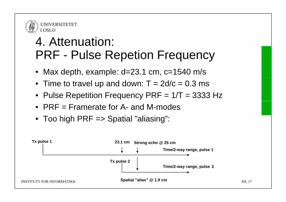
4. Attenuation: PRF Pulse Repetion FrequencyPRF - Pulse Repetion Frequency• Max depth, example: d=23.1 cm, c=1540 m/s• Time to travel up and down: T = 2d/c = 0.3 ms• Pulse Repetition Frequency PRF = 1/T = 3333 Hz• PRF = Framerate for A- and M-modes• Too high PRF => Spatial ”aliasing”:
Tx pulse 1 23.1 cm Strong echo @ 25 cm
Tx pulse 2
Time/2-way range, pulse 1
Time/2-way range, pulse 2
INSTITUTT FOR INFORMATIKK SH, 17Spatial ”alias” @ 1.9 cm
UNIVERSITETET I OSLO
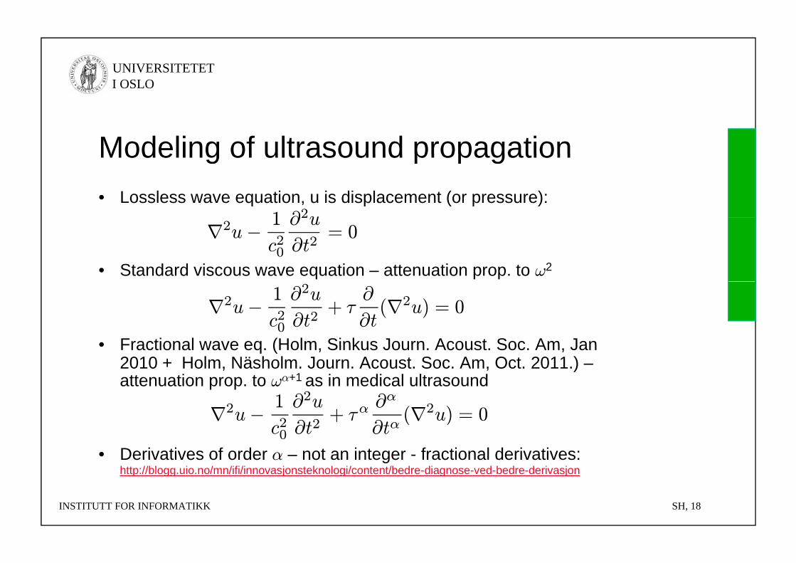
Modeling of ultrasound propagationModeling of ultrasound propagation• Lossless wave equation, u is displacement (or pressure):
1 ∂2u
• Standard viscous wave equation – attenuation prop. to ω2
∇2u− 1
c20
∂2u
∂t2= 0
• Fractional wave eq (Holm Sinkus Journ Acoust Soc Am Jan
∇2u− 1
c20
∂2u
∂t2+ τ
∂
∂t(∇2u) = 0
• Fractional wave eq. (Holm, Sinkus Journ. Acoust. Soc. Am, Jan 2010 + Holm, Näsholm. Journ. Acoust. Soc. Am, Oct. 2011.) –attenuation prop. to ωα+1 as in medical ultrasound
∇2 1 ∂2u+ α ∂α
(∇2 ) 0
• Derivatives of order α – not an integer - fractional derivatives: http://blogg.uio.no/mn/ifi/innovasjonsteknologi/content/bedre-diagnose-ved-bedre-derivasjon
∇2u−c20 ∂t2
+ τα∂tα
(∇2u) = 0
INSTITUTT FOR INFORMATIKK SH, 18
http://blogg.uio.no/mn/ifi/innovasjonsteknologi/content/bedre diagnose ved bedre derivasjon
UNIVERSITETET I OSLO
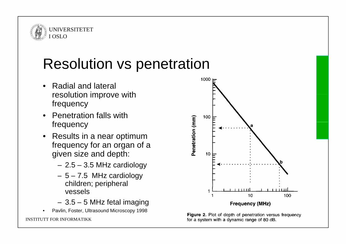
Resolution vs penetrationResolution vs penetration• Radial and lateral
resolution improve withresolution improve withfrequency
• Penetration falls withffrequency
• Results in a near optimum frequency for an organ of a given size and depth:
– 2.5 – 3.5 MHz cardiology– 5 – 7.5 MHz cardiology5 7.5 MHz cardiology
children; peripheralvessels
– 3.5 – 5 MHz fetal imaging
INSTITUTT FOR INFORMATIKK SH, 19
g g• Pavlin, Foster, Ultrasound Microscopy 1998
UNIVERSITETET I OSLO
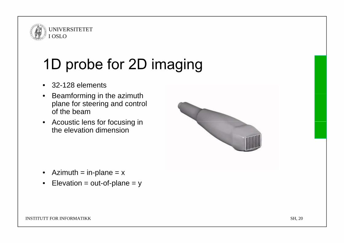
1D probe for 2D imaging• 32-128 elements
B f i i th i th
1D probe for 2D imaging
• Beamforming in the azimuth plane for steering and control of the beam
• Acoustic lens for focusing in• Acoustic lens for focusing in the elevation dimension
• Azimuth = in-plane = x• Elevation = out-of-plane = y
INSTITUTT FOR INFORMATIKK SH, 20
UNIVERSITETET I OSLO
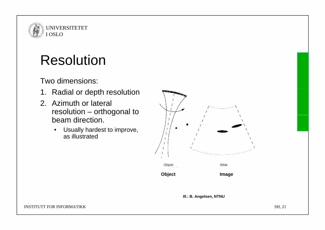
ResolutionResolutionTwo dimensions:1. Radial or depth resolution2. Azimuth or lateral
resolution – orthogonal to gbeam direction. • Usually hardest to improve,
as illustrated
Objekt Bilde
Object Image
INSTITUTT FOR INFORMATIKK SH, 21
Ill.: B. Angelsen, NTNU
UNIVERSITETET I OSLO
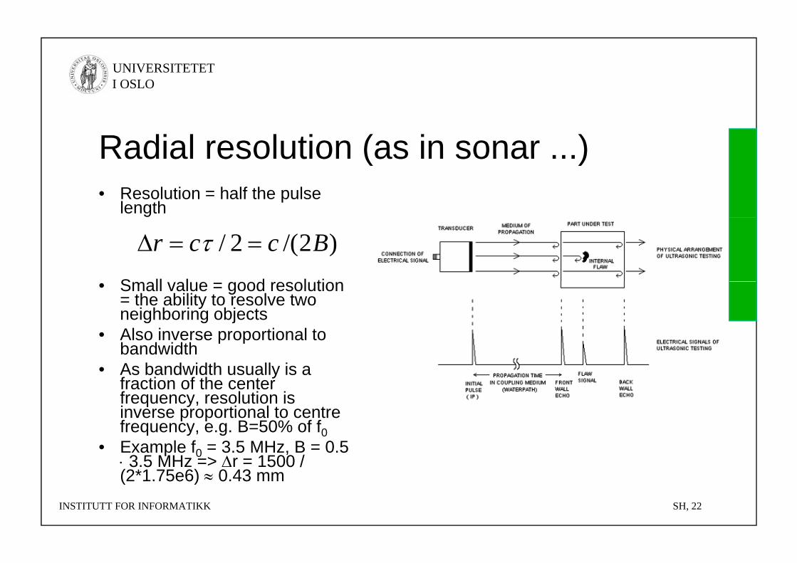
Radial resolution (as in sonar )Radial resolution (as in sonar ...)• Resolution = half the pulse
length
S ll l d l ti
)2/(2/ Bccr • Small value = good resolution
= the ability to resolve two neighboring objects
• Also inverse proportional to band idthbandwidth
• As bandwidth usually is a fraction of the center frequency, resolution is inverse proportional to centreinverse proportional to centre frequency, e.g. B=50% of f0
• Example f0 = 3.5 MHz, B = 0.5 3.5 MHz => r = 1500 / (2*1 75e6) 0 43 mm
INSTITUTT FOR INFORMATIKK SH, 22
(2*1.75e6) 0.43 mm
UNIVERSITETET I OSLO
Pulse compression in ultrasound?Pulse compression in ultrasound?NO YES• Blind zone equal to
the pulse length• Pulse Inversion in
nonlinear acousticsp g• Depth-dependent
filtering due to gfrequency dependent attenuation
INSTITUTT FOR INFORMATIKK SH, 23
UNIVERSITETET I OSLO
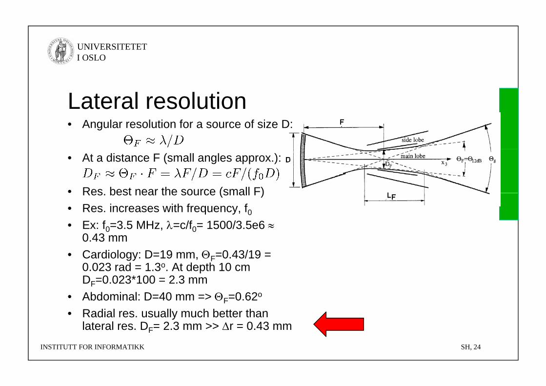
Lateral resolutionLateral resolution• Angular resolution for a source of size D:
• At a distance F (small angles approx.):
• Res best near the source (small F)Res. best near the source (small F)• Res. increases with frequency, f0• Ex: f0=3.5 MHz, =c/f0= 1500/3.5e6
0 43 mm0.43 mm• Cardiology: D=19 mm, F=0.43/19 =
0.023 rad = 1.3o. At depth 10 cm D =0 023*100 = 2 3 mmDF=0.023 100 = 2.3 mm
• Abdominal: D=40 mm => F=0.62o
• Radial res. usually much better than lateral res D = 2 3 mm >> r = 0 43 mm
INSTITUTT FOR INFORMATIKK SH, 24
lateral res. DF= 2.3 mm >> r = 0.43 mm
UNIVERSITETET I OSLO
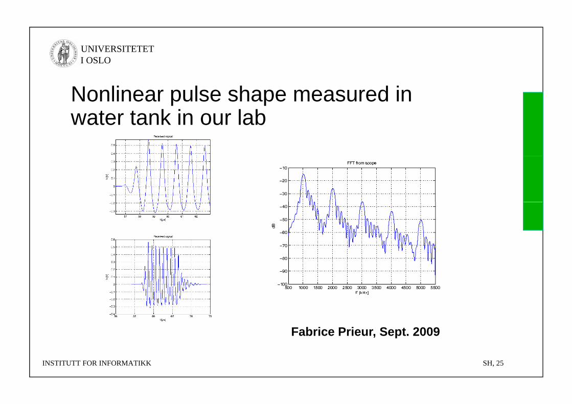
Nonlinear pulse shape measured in t t k i l bwater tank in our lab
Fabrice Prieur, Sept. 2009
INSTITUTT FOR INFORMATIKK SH, 25
UNIVERSITETET I OSLO
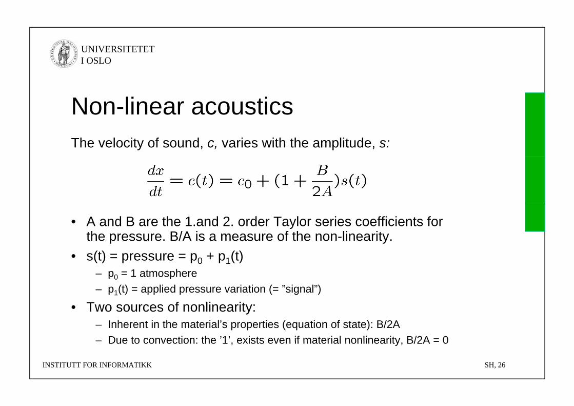
Non-linear acousticsNon linear acousticsThe velocity of sound, c, varies with the amplitude, s:
• A and B are the 1.and 2. order Taylor series coefficients for the pressure. B/A is a measure of the non-linearity.
• s(t) = pressure = p0 + p1(t)– p0 = 1 atmosphere– p1(t) = applied pressure variation (= ”signal”)1
• Two sources of nonlinearity:– Inherent in the material’s properties (equation of state): B/2A– Due to convection: the ’1’ exists even if material nonlinearity B/2A = 0
INSTITUTT FOR INFORMATIKK SH, 26
Due to convection: the 1 , exists even if material nonlinearity, B/2A = 0
UNIVERSITETET I OSLO
Non-linear acousticsNon linear acoustics• Positive peaks propagate faster than negative
kpeaks:– Waveform is distorted.– More and more energy is transferred to higher harmonics asMore and more energy is transferred to higher harmonics as
the wave propagates.– Eventually a shock wave is formed.
B/A:• B/A:– Linear medium: B/A = 0– Salt water: B/A=5.2, ,– Blood and tissue: B/A=6,..., 10.
INSTITUTT FOR INFORMATIKK SH, 27
UNIVERSITETET I OSLO
Non-linear acousticsNon linear acoustics
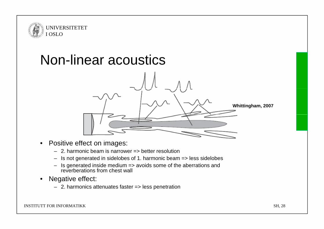
Whittingham, 2007
P i i ff i• Positive effect on images:– 2. harmonic beam is narrower => better resolution– Is not generated in sidelobes of 1. harmonic beam => less sidelobes– Is generated inside medium => avoids some of the aberrations andIs generated inside medium > avoids some of the aberrations and
reverberations from chest wall• Negative effect:
– 2. harmonics attenuates faster => less penetration
INSTITUTT FOR INFORMATIKK SH, 28
UNIVERSITETET I OSLO
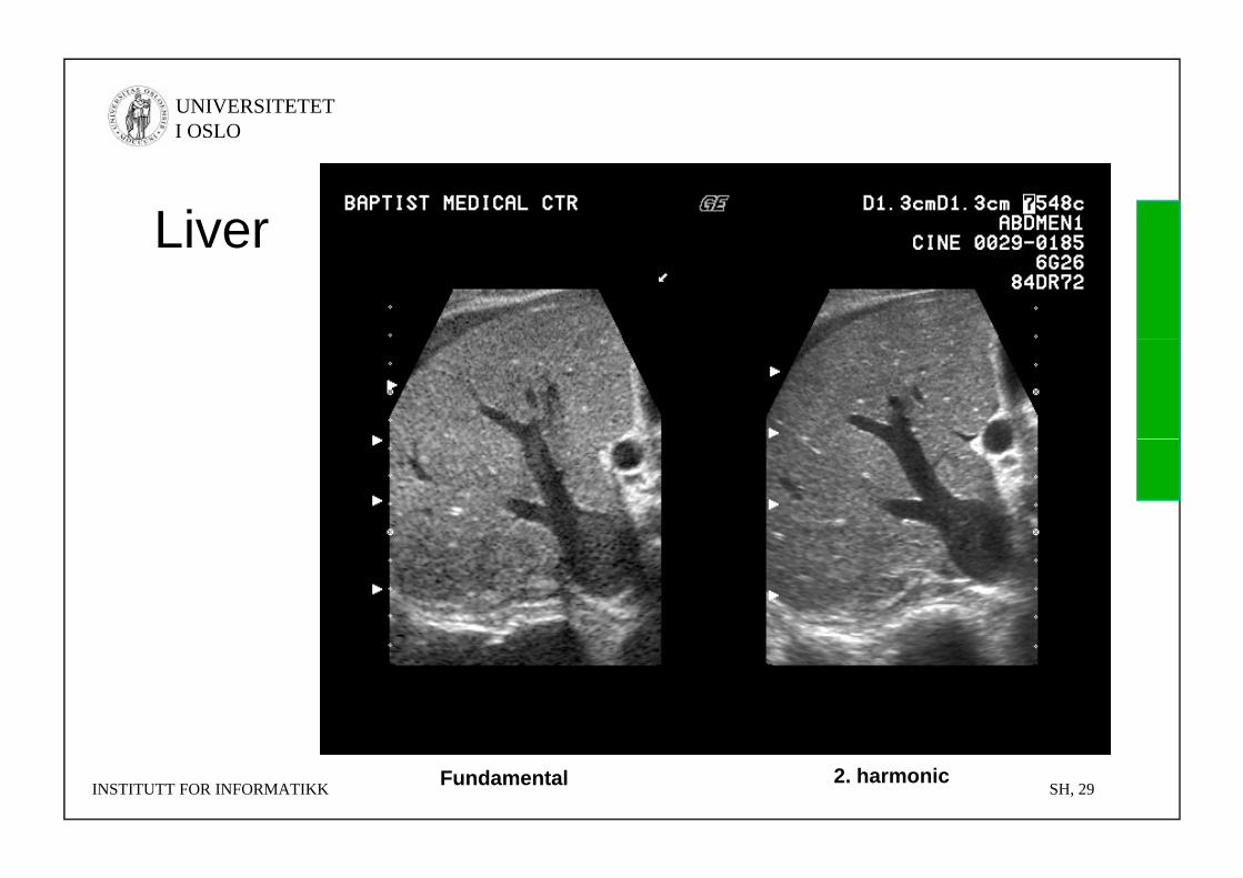
LiverLiver
INSTITUTT FOR INFORMATIKK SH, 29Fundamental 2. harmonic
UNIVERSITETET I OSLO
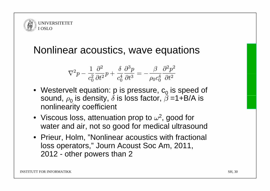
Nonlinear acoustics wave equationsNonlinear acoustics, wave equations
∇2p− 1 ∂2p+
δ ∂3p= − β ∂2p2
• Westervelt equation: p is pressure, c0 is speed of d i d it δ i l f t β 1 B/A i
∇ pc20 ∂t
2p+
c40 ∂t3=
ρ0c40 ∂t2
sound, ρ0 is density, δ is loss factor, β =1+B/A is nonlinearity coefficient
• Viscous loss attenuation prop to ω2 good for• Viscous loss, attenuation prop to ω2, good for water and air, not so good for medical ultrasound
• Prieur Holm ”Nonlinear acoustics with fractionalPrieur, Holm, Nonlinear acoustics with fractional loss operators,” Journ Acoust Soc Am, 2011, 2012 - other powers than 2
INSTITUTT FOR INFORMATIKK SH, 30

UNIVERSITETET I OSLO
Medical UltrasoundMedical Ultrasound1. Introduction2. Main principles3. Imaging modes4 Ultrasound instruments4. Ultrasound instruments5. Probe types and image
formats6. Emerging technology
INSTITUTT FOR INFORMATIKK SH, 31
UNIVERSITETET I OSLO
Medical Ultrasound ScannerMedical Ultrasound Scanner• Imaging modes:
– A-mode (A = amplitude)– M-mode (M = motion)– B-mode 2D (B = brightness)B mode 2D (B brightness)
» Harmonic imaging – octave mode
• Doppler modes:– Doppler spectrum– Color doppler– (Strain)– (Strain)
INSTITUTT FOR INFORMATIKK SH, 32
UNIVERSITETET I OSLO
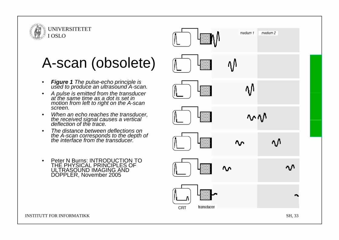
A-scan (obsolete)A scan (obsolete)• Figure 1 The pulse-echo principle is
used to produce an ultrasound A-scan. • A pulse is emitted from the transducer• A pulse is emitted from the transducer
at the same time as a dot is set in motion from left to right on the A-scan screen.
• When an echo reaches the transducer, the received signal causes a verticalthe received signal causes a vertical deflection of the trace.
• The distance between deflections on the A-scan corresponds to the depth of the interface from the transducer.
• Peter N Burns: INTRODUCTION TO THE PHYSICAL PRINCIPLES OF ULTRASOUND IMAGING AND DOPPLER November 2005DOPPLER, November 2005
INSTITUTT FOR INFORMATIKK SH, 33
UNIVERSITETET I OSLO
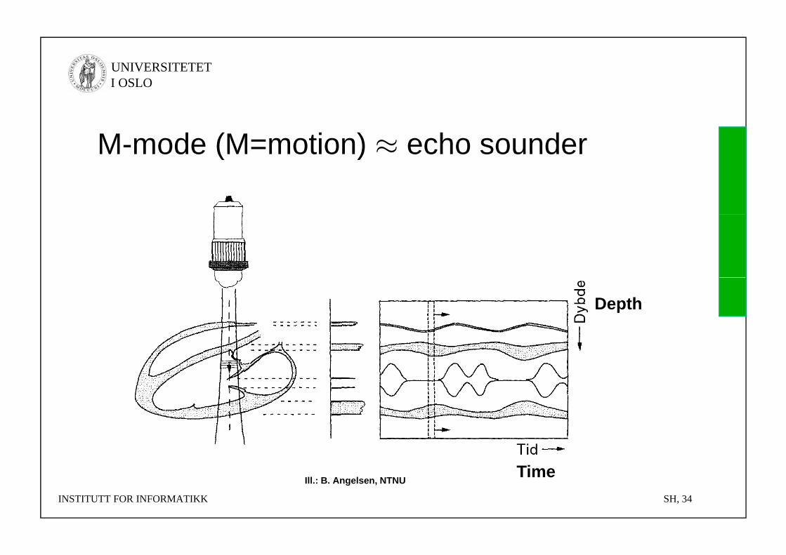
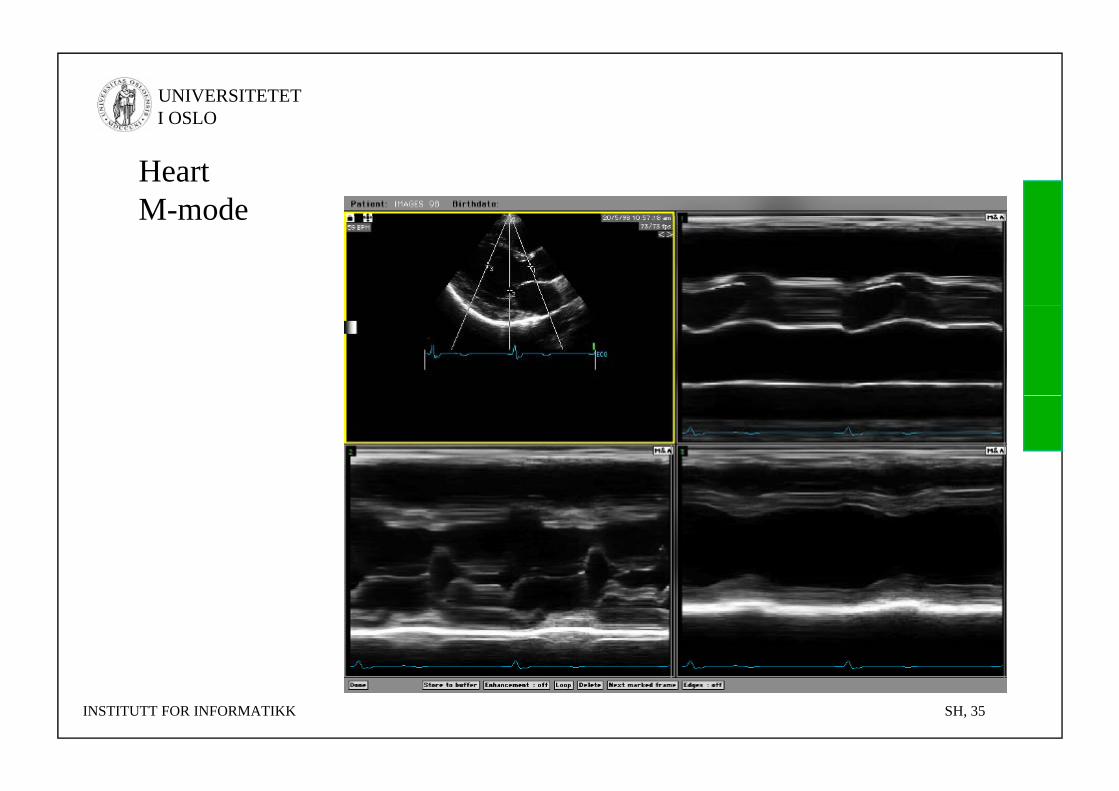
M-mode (M=motion) ≈ echo sounderM mode (M motion) ≈ echo sounder
Depth
TiINSTITUTT FOR INFORMATIKK SH, 34
TimeIll.: B. Angelsen, NTNU
UNIVERSITETET I OSLO
HeartM-modeM mode
INSTITUTT FOR INFORMATIKK SH, 35

UNIVERSITETET I OSLO
Multiple beams are sentto scan the entire volume
INSTITUTT FOR INFORMATIKK SH, 37
UNIVERSITETET I OSLO
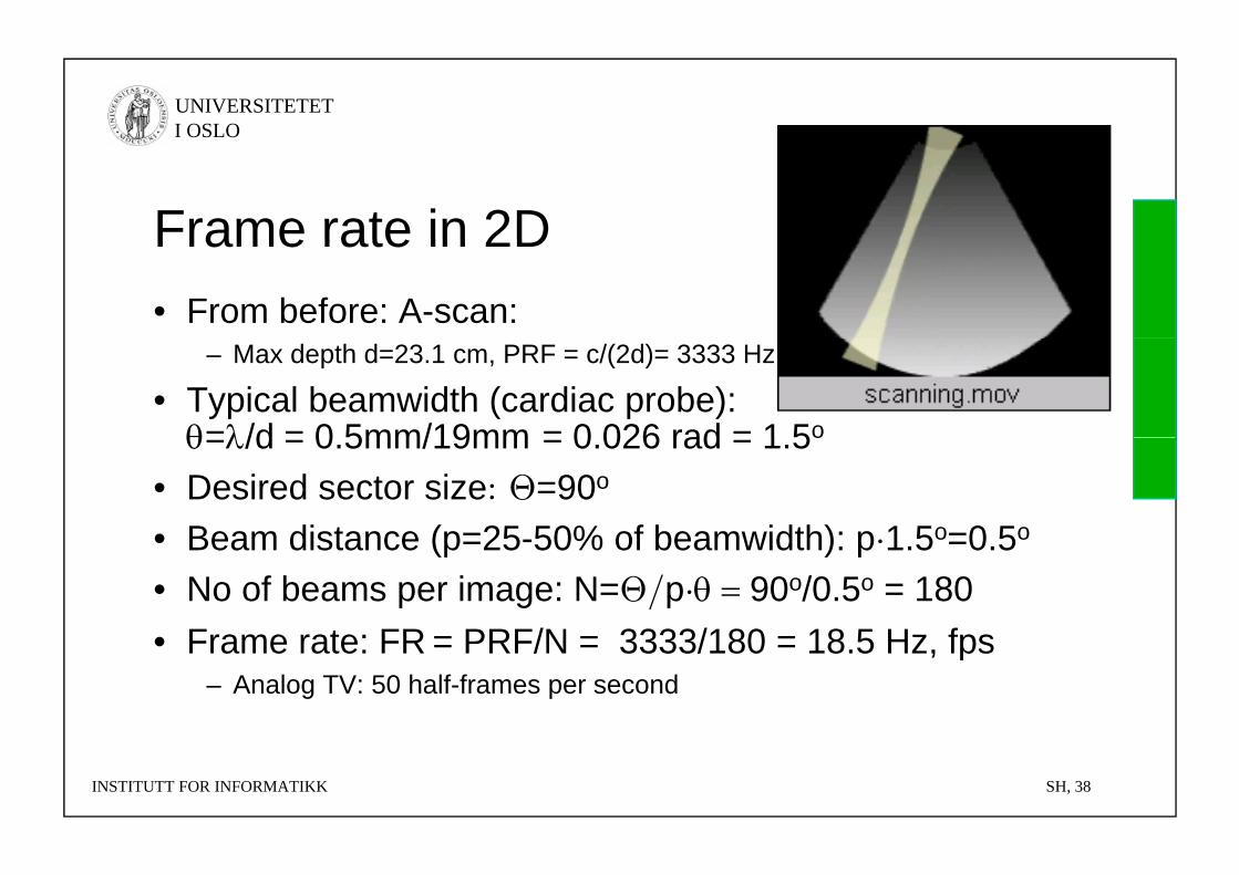
Frame rate in 2DFrame rate in 2D• From before: A-scan:
– Max depth d=23.1 cm, PRF = c/(2d)= 3333 Hz
• Typical beamwidth (cardiac probe): =/d = 0 5mm/19mm = 0 026 rad = 1 5o=/d = 0.5mm/19mm = 0.026 rad = 1.5o
• Desired sector size: Θ=90o
• Beam distance (p=25 50% of beamwidth): p 1 5o=0 5o• Beam distance (p=25-50% of beamwidth): p·1.5o=0.5o
• No of beams per image: N=Θ/p·90o/0.5o = 180 Frame rate: FR = PRF/N = 3333/180 = 18 5 Hz fps• Frame rate: FR = PRF/N = 3333/180 = 18.5 Hz, fps
– Analog TV: 50 half-frames per second
INSTITUTT FOR INFORMATIKK SH, 38
UNIVERSITETET I OSLO
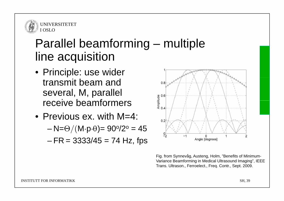
Parallel beamforming – multiple line acquisitionline acquisition• Principle: use wider
transmit beam and several, M, parallel
i b freceive beamformers• Previous ex. with M=4:
– N=Θ/(M·p·)= 90o/2o = 45– FR = 3333/45 = 74 Hz, fps
Fig. from Synnevåg, Austeng, Holm, ”Benefits of Minimum-Variance Beamforming in Medical Ultrasound Imaging”, IEEE Trans. Ultrason., Ferroelect., Freq. Contr., Sept. 2009.
INSTITUTT FOR INFORMATIKK SH, 39
UNIVERSITETET I OSLO
2D framerate2D framerate • Assume a fixed aperture, D; a fixed maximum attenuation before
next ping A; and that attenuation varies linearly with frequencynext ping, A; and that attenuation varies linearly with frequency– PRF = 1/T = c/2d = c·α·f/A
• Angular distance between receiver beams: = p/D, where p is the percentage shift relative to a beamwidth (p = 25-50% typ)p g (p yp)
– M = no of parallel rx beams, M= tx/, ratio of tx and rx beamwidths
• Angular sector to be covered:
N b f b N / /M D/ M• Number of beams: N = /tx = /M = D/pM• FR = PRF/N = cfpM/(AD) = pMc2/(A D)
– Independent of frequency with these assumptions– Explananation: As frequency increases, frame rate decreases due to narrower
beams. This cancels the increase in PRF due to a smaller depth.
INSTITUTT FOR INFORMATIKK SH, 40

UNIVERSITETET I OSLO
Medical UltrasoundMedical Ultrasound1. Introduction2. Main principles3. Imaging modes4 Ultrasound instruments4. Ultrasound instruments5. Probe types and image
formats6. Emerging technology
INSTITUTT FOR INFORMATIKK SH, 41
UNIVERSITETET I OSLO
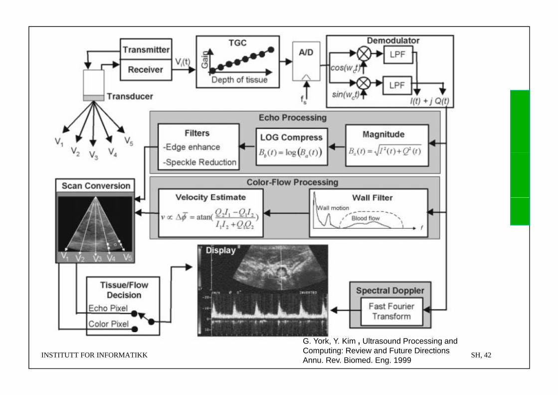
INSTITUTT FOR INFORMATIKK SH, 42
G. York, Y. Kim , Ultrasound Processing andComputing: Review and Future DirectionsAnnu. Rev. Biomed. Eng. 1999
UNIVERSITETET I OSLO
Medical Ultrasound MarketsMedical Ultrasound Markets• Cardiology (Heart) 25% of market
– Field where Norwegian company Vingmed was established in the 80’s as a startup from NTNU Now GE Vingmed Ultrasound center of excellence for cardiology ultrasound in GENTNU. Now GE Vingmed Ultrasound, center of excellence for cardiology ultrasound in GE Healthcare
– Demo later in course• Radiology (Inner organs) 40%• Obstetrics/Gynecology 20%y gy• Niches
– Vascular– Urology (B&K Medical, Denmark)– Surgery (Medistim AS and Sonowand AS)– Emergency medicine (driver for handheld ultrasound)– General practice– Dermatology (skin)– Veterinary– Small animals for medical experiments/testingp g– ...
INSTITUTT FOR INFORMATIKK SH, 43
UNIVERSITETET I OSLO
High-end Ultrasound providersHigh end Ultrasound providers• Philips
– Acquired ATL ,Seattle WA, and HP/Agilent, Boston MA
• SiemensA i d A Sili V ll– Acquired Acuson, Silicon Valley
• GE Healthcare– Acquired VingmedAcquired Vingmed
• Japan: Toshiba, Hitachi, Aloka• Emerging? France: Supersonic ImagineEmerging? France: Supersonic Imagine
INSTITUTT FOR INFORMATIKK SH, 44
UNIVERSITETET I OSLO
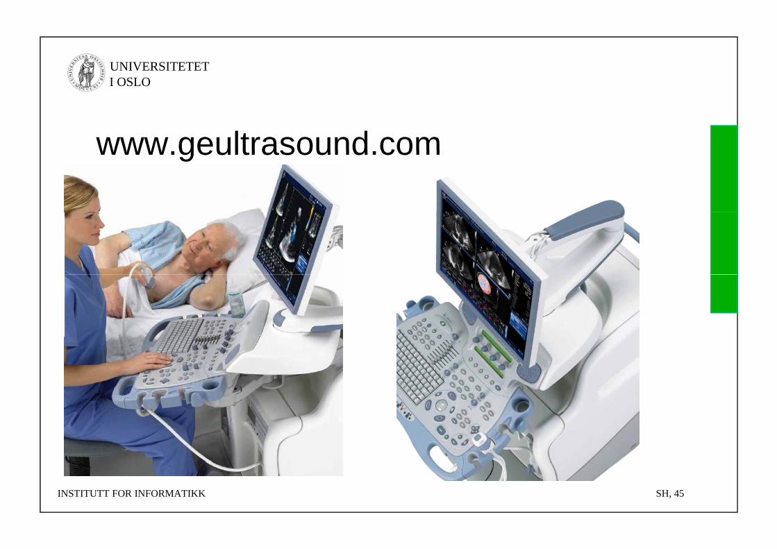
www geultrasound comwww.geultrasound.com
INSTITUTT FOR INFORMATIKK SH, 45
UNIVERSITETET I OSLO
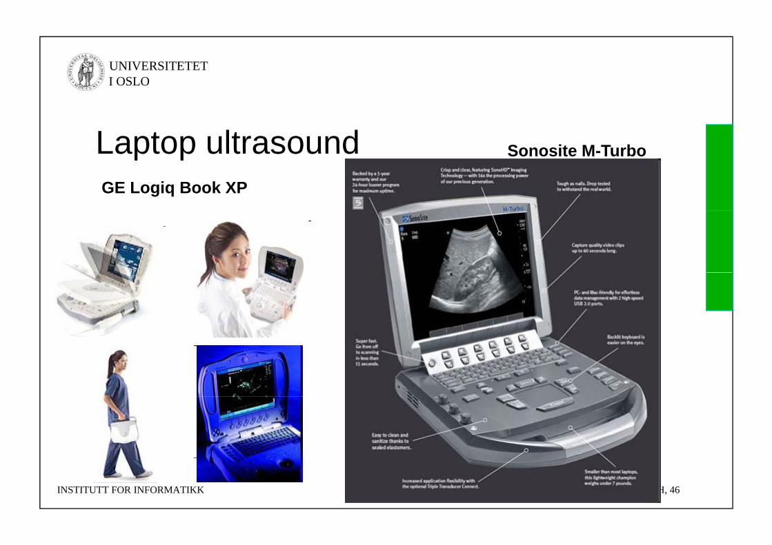
Laptop ultrasound Sonosite M TurboLaptop ultrasoundGE Logiq Book XP
Sonosite M-Turbo
INSTITUTT FOR INFORMATIKK SH, 46
UNIVERSITETET I OSLO
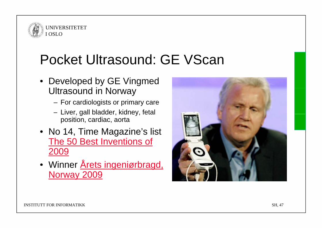
Pocket Ultrasound: GE VScanPocket Ultrasound: GE VScan• Developed by GE Vingmed
Ult d i NUltrasound in Norway– For cardiologists or primary care– Liver, gall bladder, kidney, fetalLiver, gall bladder, kidney, fetal
position, cardiac, aorta
• No 14, Time Magazine’s list The 50 Best Inventions ofThe 50 Best Inventions of 2009
• Winner Årets ingeniørbragdWinner Årets ingeniørbragd, Norway 2009
INSTITUTT FOR INFORMATIKK SH, 47
UNIVERSITETET I OSLO
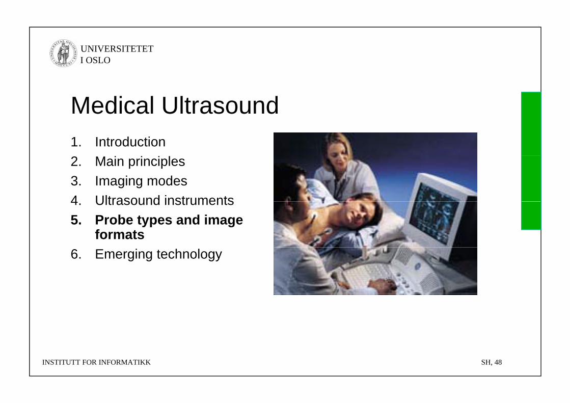
Medical UltrasoundMedical Ultrasound1. Introduction2. Main principles3. Imaging modes4 Ultrasound instruments4. Ultrasound instruments5. Probe types and image
formats6. Emerging technology
INSTITUTT FOR INFORMATIKK SH, 48
UNIVERSITETET I OSLO
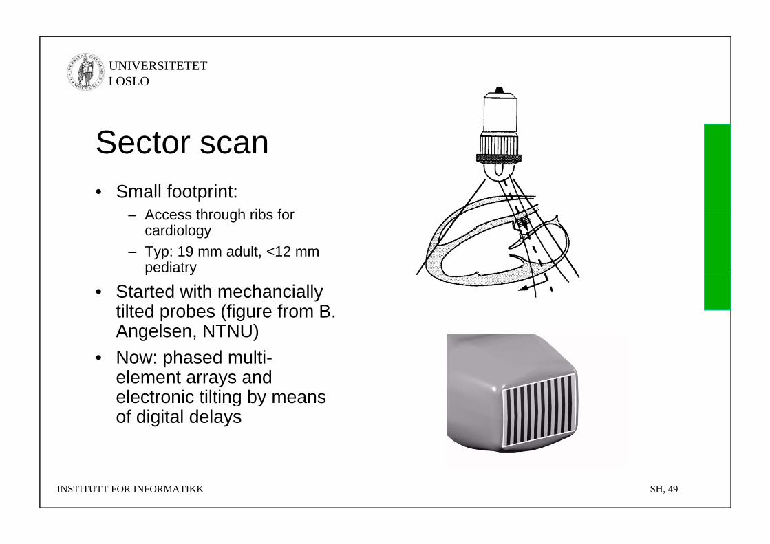
Sector scanSector scan• Small footprint:
A th h ib f– Access through ribs for cardiology
– Typ: 19 mm adult, <12 mm pediatrypediatry
• Started with mechanciallytilted probes (figure from B. Angelsen NTNU)Angelsen, NTNU)
• Now: phased multi-element arrays and electronic tilting by meanselectronic tilting by meansof digital delays
INSTITUTT FOR INFORMATIKK SH, 49
UNIVERSITETET I OSLO
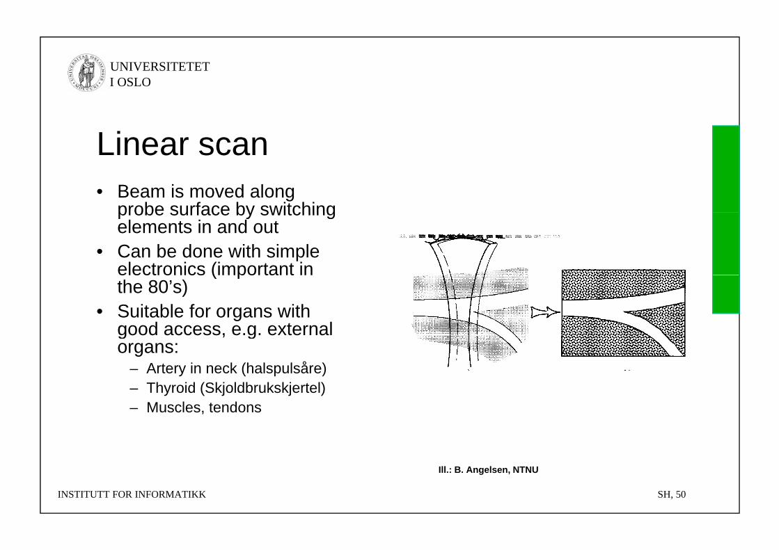
Linear scanLinear scan• Beam is moved along
probe surface by switchingprobe surface by switching elements in and out
• Can be done with simple electronics (important inelectronics (important in the 80’s)
• Suitable for organs with good access, e.g. external g , gorgans:
– Artery in neck (halspulsåre)– Thyroid (Skjoldbrukskjertel)– Muscles, tendons
INSTITUTT FOR INFORMATIKK SH, 50
Ill.: B. Angelsen, NTNU
UNIVERSITETET I OSLO
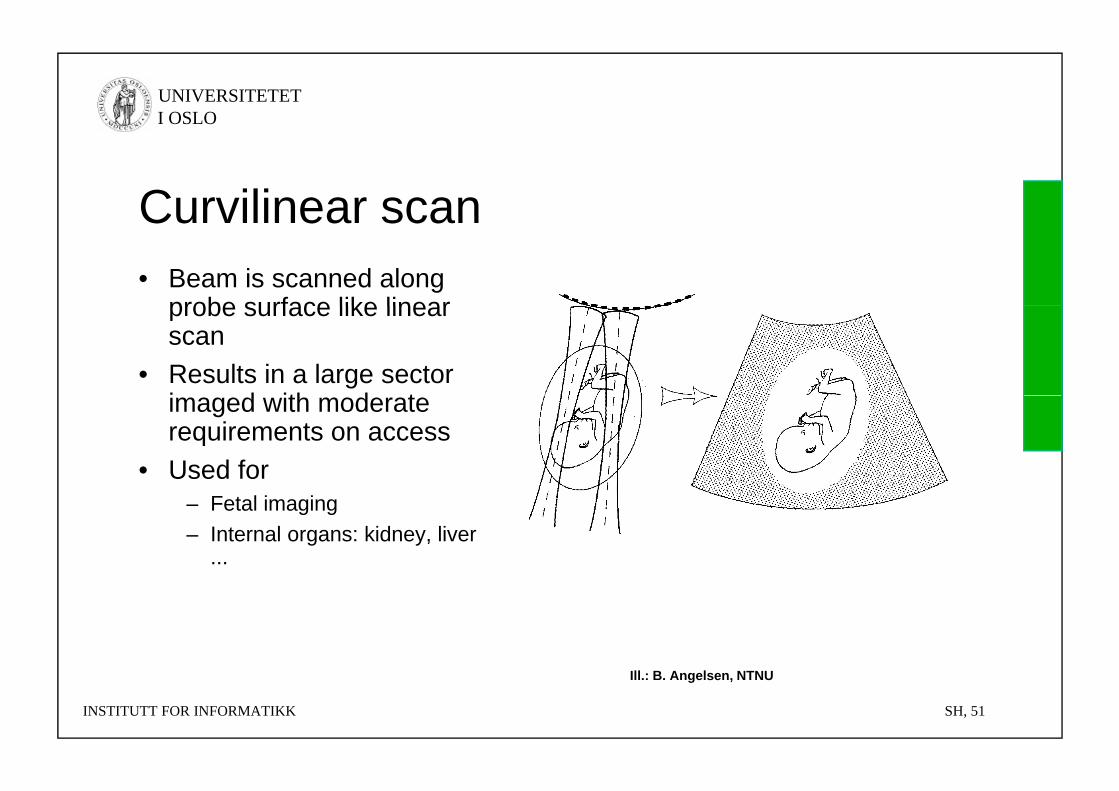
Curvilinear scanCurvilinear scan• Beam is scanned along
probe surface like linearprobe surface like linear scan
• Results in a large sector i d ith d timaged with moderate requirements on access
• Used for – Fetal imaging– Internal organs: kidney, liver
...
INSTITUTT FOR INFORMATIKK SH, 51
Ill.: B. Angelsen, NTNU
UNIVERSITETET I OSLO
Bioeffects and SafetyBioeffects and Safety• Thermal effects: heating of muscles, tendons (physiotherapy)
M h i l ff t hi f kid / ll t• Mechanical effects: crushing of kidney/gall stones, surgery• All instruments display TI and MI• TI – Thermal Index: estimate of heating in hottest part of beam
– TIS - Thermal Index Soft tissue: the most usual one– TIB - Thermal Index Bone: for bone in focal point (fetal scan)– TIC - Thermal Index Cranial: bone at probe surface (cranial imaging)
TI 1 5 ti d i id d f dl f ti– TI <1.5 centigrade is considered safe regardless of exposure time
• MI - Mechanical Index. MI = p-/f0.5 < 1.9– Risk of cavitation (sometimes called cavitation index)– Peak negative pressure in MPa– Frequency in MHz
INSTITUTT FOR INFORMATIKK SH, 52
UNIVERSITETET I OSLO
Factors which determine frame rateFactors which determine frame rate• Depth where attenuation reaches e.g. ~60 dB
– Attenuation = 2d··f– Example: 60 dB attenuation ( = 0.5 dB/cm/MHz):
» f = 2.6 MHz: d = 23.1 cm depthp
• Speed of sound• Number of transmit beams in M-, 2-D, or 3-D , ,
modes• Recap 1-D and 2-D framerate on next slides
INSTITUTT FOR INFORMATIKK SH, 53
UNIVERSITETET I OSLO
Pulse Repetion FrequencyPulse Repetion Frequency• Max depth, example: d=23.1 cm, c=1540 m/s
• Time to travel up and down: T = 2d/c = 0.3 ms
• Pulse Repetition Frequency PRF = 1/T = 3333 Hz
• PRF = Framerate for A- and M-modes
INSTITUTT FOR INFORMATIKK SH, 54
UNIVERSITETET I OSLO
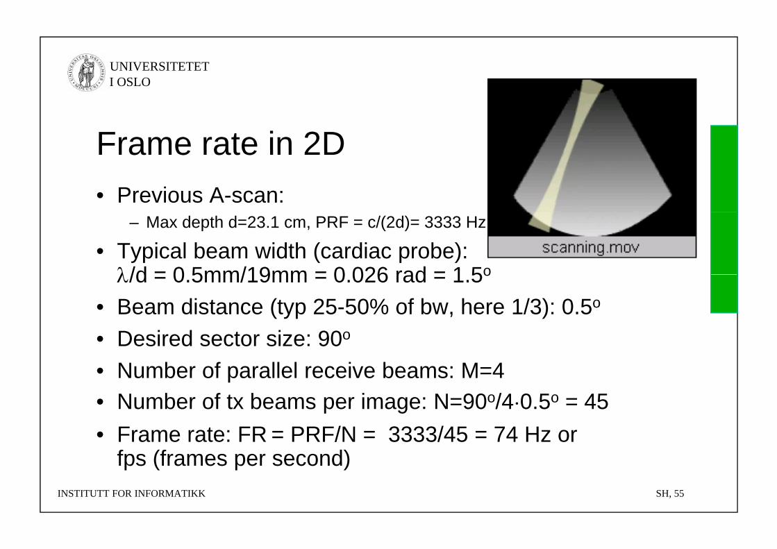
Frame rate in 2DFrame rate in 2D• Previous A-scan:
– Max depth d=23.1 cm, PRF = c/(2d)= 3333 Hz
• Typical beam width (cardiac probe): /d = 0 5mm/19mm = 0 026 rad = 1 5o/d = 0.5mm/19mm = 0.026 rad = 1.5o
• Beam distance (typ 25-50% of bw, here 1/3): 0.5o
• Desired sector size: 90o• Desired sector size: 90o
• Number of parallel receive beams: M=4• Number of tx beams per image: N=90o/4 0 5o = 45• Number of tx beams per image: N=90o/4·0.5o = 45 • Frame rate: FR = PRF/N = 3333/45 = 74 Hz or
fps (frames per second)INSTITUTT FOR INFORMATIKK SH, 55
fps (frames per second)

UNIVERSITETET I OSLO
Medical UltrasoundMedical Ultrasound1. Introduction2. Main principles3. Imaging modes4 Ultrasound instruments4. Ultrasound instruments5. Probe types and image
formats6. Emerging technology
INSTITUTT FOR INFORMATIKK SH, 56
UNIVERSITETET I OSLO
Emerging technologyEmerging technology• Not really emerging, but still quite new: 3D• Elastography
INSTITUTT FOR INFORMATIKK SH, 57
UNIVERSITETET I OSLO
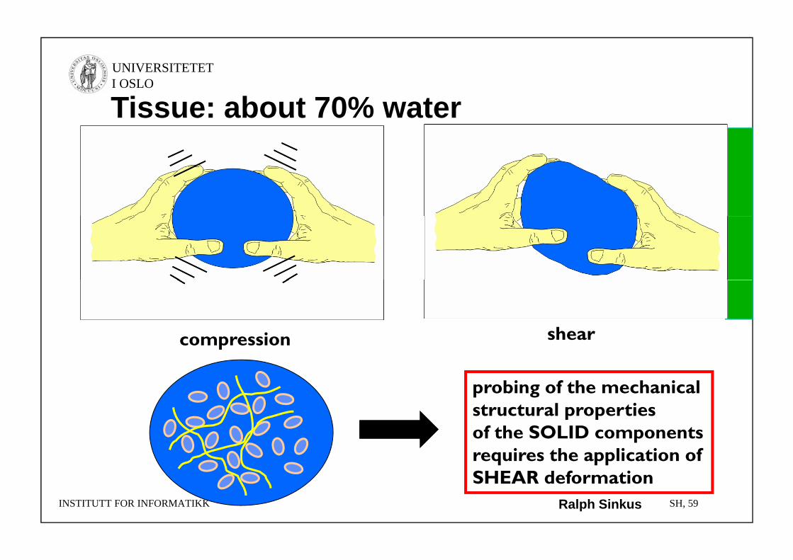
Tissue: about 70% water
compression shearcompression
probing of the mechanicalstructural propertiesstructural propertiesof the SOLID componentsrequires the application ofSHEAR d f i
INSTITUTT FOR INFORMATIKK SH, 59
SHEAR deformationRalph Sinkus
UNIVERSITETET I OSLO
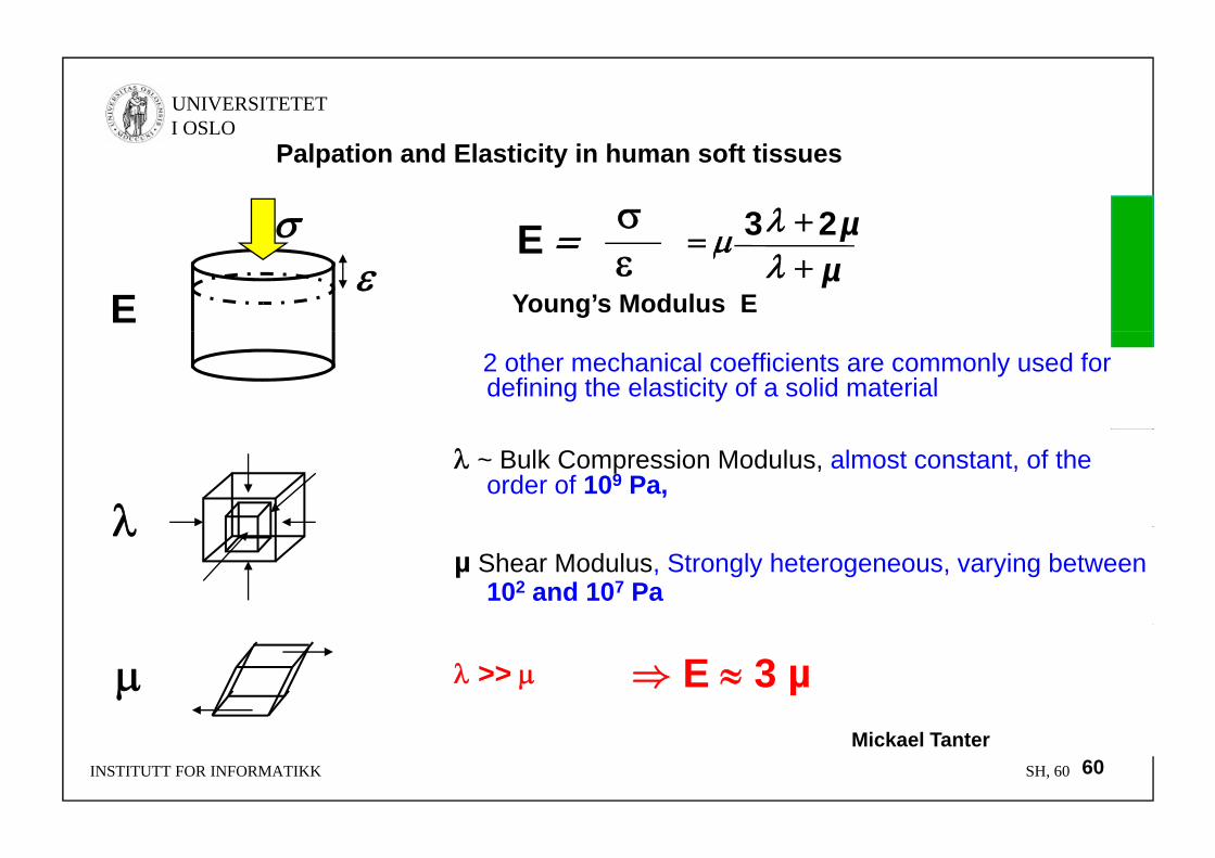
E
Palpation and Elasticity in human soft tissues
µ 23E
Young’s Modulus EEµµ
23
2 other mechanical coefficients are commonly used for defining the elasticity of a solid material
~ Bulk Compression Modulus, almost constant, of the order of 109 Pa,
µ Shear Modulus, Strongly heterogeneous, varying between
102 and 107 Pa
>> ⇒ E 3 µ
INSTITUTT FOR INFORMATIKK SH, 60 60Mickael Tanter
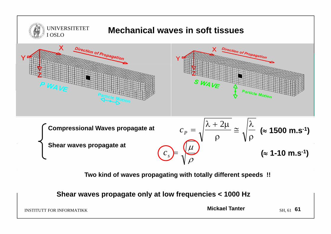
UNIVERSITETET I OSLO Mechanical waves in soft tissues
Compressional Waves propagate at
Sh t t
2
Pc ( 1500 m.s-1)
Shear waves propagate at
sc ( 1-10 m.s-1)
Two kind of waves propagating with totally different speeds !!
Shear waves propagate only at low frequencies < 1000 Hz
INSTITUTT FOR INFORMATIKK SH, 61
p p g y q
61Mickael Tanter
UNIVERSITETET I OSLO
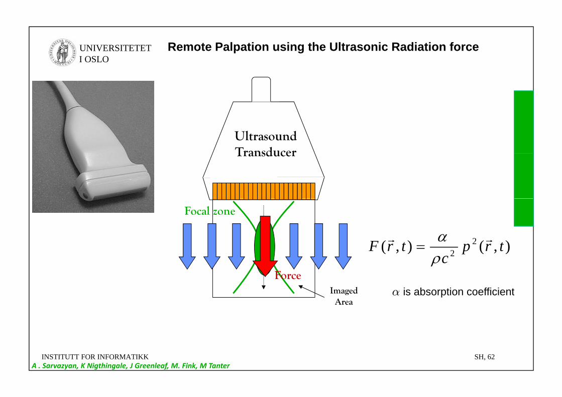
Remote Palpation using the Ultrasonic Radiation force
Ultrasound TransducerTransducer
Focal zone
)()( 2 ttF
I d
Force
),(),( 22 trp
ctrF
i b ti ffi i tImaged Area
α is absorption coefficient
INSTITUTT FOR INFORMATIKK SH, 62A . Sarvazyan, K Nigthingale, J Greenleaf, M. Fink, M Tanter
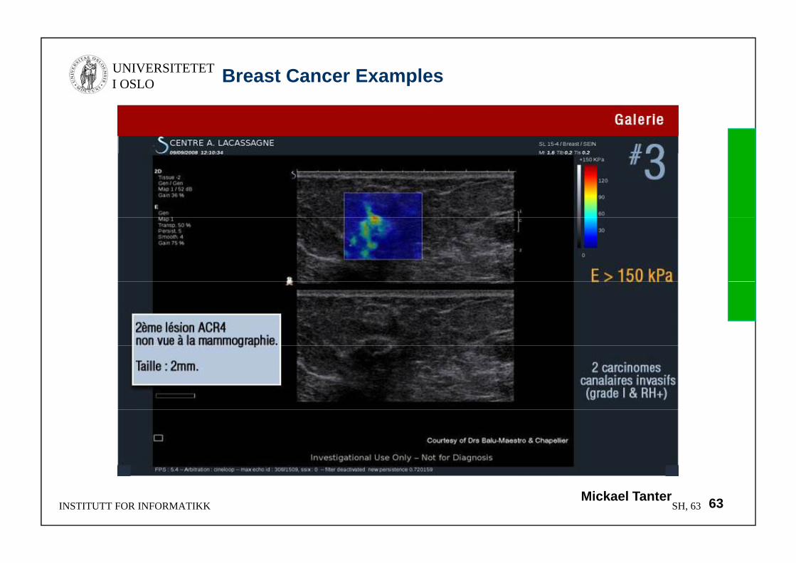
UNIVERSITETET I OSLO Breast Cancer Examples
INSTITUTT FOR INFORMATIKK SH, 63 63Mickael Tanter
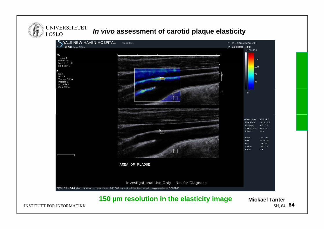
UNIVERSITETET I OSLO In vivo assessment of carotid plaque elasticity
INSTITUTT FOR INFORMATIKK SH, 64150 µm resolution in the elasticity image
64Mickael Tanter


![[PPT]Process Documentation - Forsiden - Universitetet i Oslo · Web viewProcess Documentation Dr.Zubeeda Quraishy Dept of Informatics University of Oslo, Norway Process Documentation](https://static.fdocuments.us/doc/165x107/5aefb9a77f8b9aa9168cff30/pptprocess-documentation-forsiden-universitetet-i-viewprocess-documentation.jpg)