Mechanized Pedestrian for Automated Vehicle Development
52
Mechanized Pedestrian for Automated Vehicle Development April 23, 2015 Sponsored by University of Michigan Mobility Transformation Center Professor Huei Peng Dr. Jim Sayer University of Michigan ME 450 Winter 2015, Team 13 Abby Crane Seth Gable Brendan Kawar Calvin Wang
Transcript of Mechanized Pedestrian for Automated Vehicle Development

Mechanized Pedestrian for Automated Vehicle Development
April 23, 2015
Sponsored by University of Michigan Mobility Transformation Center
Professor Huei Peng Dr. Jim Sayer
University of Michigan
ME 450 Winter 2015, Team 13 Abby Crane Seth Gable
Brendan Kawar Calvin Wang

EXECUTIVE SUMMARY In 2011 there were 4,432 pedestrian deaths due to automotive collisions, accounting for 14% of total automobile fatalities [1]. With the National Highway Transportation Safety Administration (NHTSA) recommending that new-model vehicles come equipped with dynamic brake support [2], automotive manufacturers have begun researching and implementing collision detection systems in their products. The development of this autonomous vehicle technology has sparked the demand for proper pedestrian avoidance test systems. Current industry testing devices are either too complex and expensive or over-simplified. Professor Huei Peng and Dr. James Sayer from the University of Michigan Mobility Transformation Center (MTC) are sponsoring the Mechanized Pedestrian for Automated Vehicle Development project. The project aims to create a mechanized pedestrian for use in the MTC’s testing facility, where automated vehicle Pedestrian Crash Avoidance/Mitigation (PCAM) systems will be verified. The sponsors request that the mechanized pedestrian look and walk like an adult human, is portable, and can be quickly reset. A functioning prototype and documented design considerations are to be submitted upon completion. The mannequin design was derived from a previous ME450 team. However, their prototype was incapable of walking in a stable manner and did not meet speed requirements. The feet, torso, and motor input were identified as the areas of direct contribution to these failures and have been re-designed based on technical analysis. A functioning mannequin with better movement, stability, and speed has been created. The prototype allows for proper arm and leg motion without the use of an external support structure, separating the final concept from current industry testing devices. This product will not go into mass production and is estimated to cost within $1500. We have improved the mannequin’s balance by re-designing its three major subsystems: the feet, the torso, and motor control. Results from validation testing confirm that the motors are powerful enough to meet the required walking speed. Dimensional requirements have also been achieved within tolerances. The torso frame now consists of a lighter material and has lowered the mannequin’s center of mass, improving balance. With these improvements, our mannequin is almost fully capable of meeting the speed requirement, but falls just short. The helical gears in the hip mechanism prevent the mannequin from standing upright at higher walking speeds. The amount of force occurring in the hip shafts is larger than we expected, causing the gears to skip teeth. Additionally, the foot motion currently uses an open loop control resulting in inconsistent motion trajectory. Solving the remaining issues will make the mannequin useable for testing. Replacing the helical gears with more robust gears and increasing the hip shaft diameter may be the easiest and quickest ways to solve the front-back swaying. Additionally, a new encoder must be purchased in order to integrate a closed loop feedback control to have a consistent motion trajectory. The coding needs to be modified accordingly. Lastly, incorporating a detachable ankle plate that can disconnect the feet from the body will help protect the components in the feet. With these changes, we believe that the mannequin will be able to meet all the requirements for a fully functional mechanized pedestrian.
1
Table of Contents 1.0 Background ................................................................................................................................4
1.1 Project Description .............................................................................................................................. 4 1.2 Benchmarks......................................................................................................................................... 4
2.0 User Requirements & Engineering Specifications ....................................................................5 2.1 User Requirements .............................................................................................................................. 5 2.2 Engineering Specifications ................................................................................................................. 6
3.0 Concept Generation ...................................................................................................................6 3.1 Functional Decomposition .................................................................................................................. 6 3.2 External Drive ..................................................................................................................................... 7 3.3 Dynamic Base with Support Beam ..................................................................................................... 8 3.4 Pulley System...................................................................................................................................... 8 3.5 Motorized Feet .................................................................................................................................... 8
4.0 Concept Selection ......................................................................................................................8 4.1 Scoring ................................................................................................................................................ 8 4.2 Preliminary Foot Concept ................................................................................................................... 9
5.0 Engineering Analysis ...............................................................................................................10 5.1 Wheel Configuration ......................................................................................................................... 10 5.2 Center of Mass .................................................................................................................................. 11 5.3 Torso Frame Thickness ..................................................................................................................... 12 5.4 Shaft Torsion ..................................................................................................................................... 12 5.5 Motor Requirement ........................................................................................................................... 13
6.0 Final Design .............................................................................................................................15 6.1 Torso ................................................................................................................................................. 15 6.2 Hip Gears .......................................................................................................................................... 16 6.3 Foot ................................................................................................................................................... 17 6.4 Motion Generation & Motor Input.................................................................................................... 18 6.5 Risk Analysis .................................................................................................................................... 19
7.0 Design Changes .......................................................................................................................20 7.1 Shoulder Belt .................................................................................................................................... 20 7.2 Keyseat Location .............................................................................................................................. 20 7.3 Battery Mounting .............................................................................................................................. 20 7.4 Keyway in Helical Gears .................................................................................................................. 21
8.0 Validation Protocol ..................................................................................................................22
9.0 Discussion ................................................................................................................................22 9.1 Design Critique ................................................................................................................................. 22 9.2 Future Work ...................................................................................................................................... 23
9.2.1 Hip Gears .............................................................................................................................. 23 9.2.2 Hip Shafts ............................................................................................................................. 23 9.2.3 Detachable Ankle .................................................................................................................. 23 9.2.4 Electronics ............................................................................................................................ 23 9.2.5 Programming......................................................................................................................... 23
2

10.0 Manufacturing ........................................................................................................................23 10.1 Bill of Materials .............................................................................................................................. 23 10.2 Manufacturing Plans ....................................................................................................................... 25
11.0 Appendix ................................................................................................................................28 11.1 Appendix A: Additional Concepts .................................................................................................. 28 11.2 Appendix B: Supplementary Sketches ............................................................................................ 30 11.3 Appendix C: State Machine for Trajectory Generation .................................................................. 32 11.4 Appendix D: Manufacturing Drawings ........................................................................................... 33 11.5 Appendix E: Individual Ethical Design and Environmental Impact Statements ............................ 46
12.0 Acknowledgements ................................................................................................................50
13.0 References ..............................................................................................................................50
Bios ................................................................................................................................................51
3

1.0 BACKGROUND
Recently, automotive and software companies have started developing vehicles capable of driving on their own. These autonomous vehicles use complex sensors to detect objects as they travel. Automated braking systems decrease the probability of collisions with pedestrians or other vehicles, and are the first step toward self-driving cars. As more automated systems arrive on the market, NHTSA will begin considering these features in their safety ratings. 1.1 Project Description The sponsors of the project, Professor Huei Peng and Dr. James Sayer from the University of Michigan Mobility Transformation Center (MTC), require a means to test their Pre-Collision System (PCS). They request a mechanism that will mimic the body motion of an average sized adult male. This mechanized pedestrian will later be used at the MTC testing facility. Our team will improve upon the design of a previous concept from ME450 Fall 2014. 1.2 Benchmarks The previous design provides our team with a good foundation, but still requires improvements in some aspects. Figure 1 below shows the current mannequin design, which satisfies appearance and leg-arm motion transmission. However, design concepts such as mechanical balancing and motor actuation prevent the mannequin from meeting speed and distance requirements. Due to the mannequin’s inability to walk properly, the control system has not been implemented. We have found documentation of development work at two automotive companies that serves as benchmark information and helps provide us with new ideas.
Figure 1: Previous concept from Fall 2014
Toyota, in collaboration with students at the Indiana University-Purdue University Indianapolis (IUPUI) [3], developed the testing device pictured in Figure 2(a). The kinematic movement of the mannequin is a very accurate representation of a real human. Another benefit of this system is the low-weight, durable, and soft material of the dummy. It allows for minimal vehicle damage and quick re-assembly. However, this apparatus is extremely large, and takes substantial time and effort to move. Ford tests their vehicle with their in-house developed “Pre-Collision Assist and Pedestrian Detection Technology” shown in Figure 2(b). Their setup involves a mannequin
4

that slides upon a base along a track located on the ground. Although portable and easy to operate, this method does not incorporate any arm or leg movement [4].
(a) (b)
Figure 2: Two different pedestrian testing apparatuses. Toyota uses a mannequin connected to a gantry (a) and Ford pulls a mannequin across a grounded track (b).
2.0 USER REQUIREMENTS & ENGINEERING SPECIFICATIONS 2.1 User Requirements The Crash Imminent Braking (CIB) Consortium, partnered with the NHTSA, outlines the four most common pedestrian collision scenarios shown below in Figure 3: (S1) pedestrian crossing in front of a forward-traveling vehicle (88% of estimated fatalities), (S2) pedestrian crossing in front of right-turning vehicle (less than 1% of estimated fatalities), (S3) pedestrian crossing on front of left-turning vehicle (no estimated fatalities), and (S4) pedestrian traveling alongside a forward-traveling vehicle (12% of estimated fatalities) [5]. Our final product should be fully capable of simulated these four scenarios.
Figure 3: Four different crash scenarios involving pedestrians. S1 and S4 account for the most fatalities. Our primary task is to create a mannequin that mimics human motion as closely as possible, focusing on walking speed and kinematic movements of limbs. Unlike the current design by Toyota, our mannequin will not depend on an overhead gantry for its movement. Operating without an overhead gantry greatly improves the portability of the mannequin and its components. With this in mind, our mannequin must also be lightweight, yet robust enough to withstand a car’s impact at slow speeds. The user must be able to reset the system quickly. Since testing may occur outdoors, our mannequin must be fully functional in light precipitation. Our
5

team must take this into consideration when mounting all electronic components. Table 1 below shows the desired properties of the mechanized pedestrian. 2.2 Engineering Specifications
User Requirements Property Goal
Resemble an Average-Sized Human Male
Height 1.7±0.1 m Torso Length 0.9±0.1 m Torso Width 0.6±0.1 m Torso Depth 0.3±0.1 m Stride Length 0.8±0.1 m
Walking Speed 1-1.5 m/s Arm and Leg Motion ----------
Portability Weight < 23 kg
Handles for Carrying ----------
Durability Waterproof Light Precipitation Resistance to Damage Up to 2.2 m/s
Quick Reset Reset Time < 2 min Table 1: Mechanized pedestrian requirements.
As specified by our sponsors, the dimensions of the mannequin are set to mimic a 50th percentile adult male [6] and the continuous walking speed should also be similar to the average walking speed. In addition to our sponsors’ requirements, we assumed that the walking distance of the mannequin to be 10 meters to cross a double lane road [7]. The mannequin needs to be portable for the users to easily change the test scenario, therefore our team is considering implementing handles to simplify moving the device. The effort required to move the device will be greatly reduced by keeping the weight under the average person’s lifting force [6]. Our team aims to keep the weight close to the current design’s 21.3 kg. An external requirement for safety during transportation will be taken into consideration regarding any sharp metal corners that could potentially injure someone. Testing may occur in different weather conditions, thus the mechanized pedestrian will need to operate under light precipitation. To meet safety requirements, electrical components must be mounted so that they cannot get wet or users don’t come into contact with live wires. Along with electrical safety, our mannequin will withstand low speed impacts from test vehicles. Regardless of collision or successful avoidance, our mannequin is required to be reset in less than 2 minutes. 3.0 CONCEPT GENERATION 3.1 Functional Decomposition To assist concept generation, we created a functional decomposition of the electrical and mechanical subsystems needed to produce the desired motion (Figure 4). This chart breaks down the different areas our team focused on when brainstorming design ideas. Figure 5 shows the preliminary sketches for our concept generation.
6

Figure 4: Orange boxes are external inputs to the system, blue boxes are major motion components, and green boxes are for mounting.
Figure 5: Preliminary sketches for concept generation. 3.2 External Drive An external drive system incorporates a driving mechanism containing all electrical components and is located to the mannequin’s side. Two transmission lines connect the driving mechanism to the feet, providing purely mechanical leg and arm motion. Encasing the electrical components makes the system weatherproof and reduces the risk of damage from vehicle impact. Also, the increased contact area with the ground improves balance. However, the external driving box reduces portability and may interfere with some detection systems.
7

3.3 Dynamic Base with Support Beam The dynamic base concept separates the mannequin’s forward linear motion from the leg and arm motion. One motor moves the base while linear actuators within the base power leg and arm motion. The mannequin is connected to the dynamic base by a support beam, keeping the height of the torso constant and reducing the load on the motor. The concept allows for possible knee joints, which more accurately reflect human leg motion. However, the base and the support beam may interfere with some detection systems.
3.4 Pulley System Similar to the external drive system, all electrical components are housed in a separate mechanism located on the side of the road. This mechanism uses a windlass to pull each individual foot, actuating the body, leg, and arm motion. Electrical components are better protected because they are located away from the immediate crash site. Additionally, this method gives us more freedom to design the mannequin. 3.5 Motorized Feet This concept focuses on reducing the size of the current feet to improve overall stability. A different battery, 4-wheel configuration, and central ankle placement will be implemented. The motor and brake are re-positioned while the battery is mounted to the lower leg. By re-packaging the components, we can achieve better weight distribution across the foot and improve balance while walking. We also aim to increase human resemblance by decreasing the overall foot size.
4.0 Concept Selection
After presenting our concepts, our sponsors expressed concerns about using a support beam and/or external components, as they could interfere with the detection sensors. We proposed using different materials to “hide” these features, but they suggested that materials used in our prototype should not favor one manufacturer’s technology over another. 4.1 Scoring With overall re-design concepts rejected, we were encouraged to improve the existing design. With this in mind, we weighted and scored each category based on the opinions of our sponsors. Balance and speed were considered most important, as they would determine the prototype’s capability of walking at an acceptable level. Second came human resemblance and arm-leg motion, followed by manufacturability, reset time, portability, weather resistance, and power consumption. Cost and durability were least important since many of the components are already available and our prototype will only undergo light testing for now. The Pugh chart on the next page shows how each concept scored.
8

Table 2: Human resemblance played the largest factor in our concept selection. Concepts utilizing any external entities received lower scores. 4.1 Preliminary Foot Concept After sponsor input and Pugh chart analysis, our final chosen concept is to re-design the existing feet. Overall foot size will decrease and contain 4 wheels (2 driven, 2 support). A flatter, compact battery will be mounted to the lower leg, so that the motor, wheels, and brake can be re-packaged into a smaller area. To achieve even weight distribution, the ankle joint will be centered on the foot, as opposed to the rear corner. Figure 6 shows a comparison between the current and proposed foot design.
(a) (b) (c)
Figure 6: Model of the current foot design (a and b) compared with proposed design (c). Our team chose the configuration shown in Figure 6(c) due its small volume and simple drivetrain. A belt drive transmission allows us to distribute the weight evenly in the foot by centering the motor. The chosen concept, while meeting our size constraints very effectively, challenges us to package the components closely together, yet still allow for installation. One way we mitigated this packaging problem is by moving the battery (shown in light blue) up to the lower leg, reducing the number of components that must be packed into that area. Figure 7 demonstrates why the use of four wheels will provide better balance than a 3-wheel configuration.
9

Figure 7: 4 wheels provide a wider area for the robot’s center of gravity to move about.
5.0 ENGINEERING ANALYSIS 5.1 Wheel Configuration
Figure 8: Current wheel configuration (left) vs proposed design (right). Utilizing 4 wheels better distributes the weight and increases balance. The current foot design incorporates a 3-wheel configuration: one small wheel positioned at the front, one small wheel positioned at the rear corner, and one large wheel positioned inside the base. The top left of Figure 8 shows the bottom of the smaller wheels dimensioned 8 mm higher than the larger wheel, causing insufficient ground contact and allowing rotation about the foot’s lateral axis. The bottom left of Figure 8 portrays the weight distribution from the upper body throughout the foot, found by summing the forces and torques (Equations 1-3). This uneven force distribution amplifies the foot rotation, causing instability and preventing smooth foot motion. The right side of Figure 8 shows the proposed foot design, dimensioning the wheels to have equal ground contact and distributing the mannequin’s weight evenly across four wheels. Better surface contact with the ground improves traction and the improved weight distribution provides a more stable walking motion.
N1 = 0.6F
N2 = 0.1F
N3 = 0.3F
F
F
F/4 F/4
F/4
F/4
10

5.2 Center of Mass The center of mass (COM) of any object should be positioned over the support base to prevent tipping. Figure 9 shows the simplest competent model for our mannequin, assuming the center of mass is located near the geometric center in the horizontal plane. We will ensure that the center of mass does not stray too far from this geometric center by keeping the mannequin symmetric.
Figure 9: Stability is quantified by phi max, the maximum allowable tilt angle before tipping.
Equations 4 and 5 show the relationship between COM height, mass distribution, and phi max. From these equations, we determined that decreasing the COM height increases phi max. Assuming a fixed height for each of the components, we can only control COM height through component mass. Specifically, the torso mass has the greatest effect on decreasing COM height. One kilogram of mass reduction in the torso lowers the COM height by approximately 40 mm and increases phi max by approximately 2°. With this understanding, our team opted to reduce torso mass.
(Eq. 1)
(Eq. 2)
(Eq. 3)
(Eq. 4)
(Eq. 5)
11

5.3 Torso Frame Thickness We determined the necessary thickness of Delrin plate to provide sufficient structural rigidity. By modeling the torso frame as a cantilever beam, we determined the deflection per unit force for different thicknesses (Figure 10). A quarter inch sheet deflects 49.8mm per newton force (Eq. 7), whereas a half inch plate only deflects 6.23 mm (Eq. 9). Therefore, we chose to use a half inch plate.
Figure 10: Deflection caused by force applied at the top of torso side frame.
Quarter Inch:
𝐿𝐿 = 0.4953 𝑚𝑚 𝐸𝐸 = 3𝐺𝐺𝐺𝐺𝐺𝐺
𝐼𝐼 = 112
(0.0127)(0.00635)3 = 2.71 ∙ 10−10 (Eq. 6) 𝛿𝛿𝐹𝐹
= 𝐿𝐿3
3𝐸𝐸𝐸𝐸= 0.0498 𝑚𝑚
𝑁𝑁 (Eq. 7)
Half Inch: 𝐼𝐼 = 1
12(0.0127)4 = 2.168 ∙ 10−9 (Eq. 8)
𝛿𝛿𝐹𝐹
= 𝐿𝐿3
3𝐸𝐸𝐸𝐸= 0.00623 𝑚𝑚
𝑁𝑁 (Eq. 9)
5.4 Shaft Torsion A possible cause of front-back tilt is the torsion in the hip shafts. We analyzed the current 8mm diameter shaft to determine if it had a significant impact on this tilt. At full stride (Figure 11), the shaft would be subject to 1.82 Nm of torque (Eq. 11), causing 1.31º of twist (Eq. 14). This twist in the hip shaft causes 0.65º tilt in the body, which is not a significant factor.
12

Figure 11: FBD for hip shaft torsion. Shaft Torsion:
𝜙𝜙𝑇𝑇
= 𝑙𝑙𝐺𝐺𝐽𝐽𝑡𝑡
(Eq. 10)
Determining Torque: 𝑇𝑇 = 𝐿𝐿𝑠𝑠𝑡𝑡𝑠𝑠𝑠𝑠𝑠𝑠𝑠𝑠
4∙ 𝑊𝑊𝐿𝐿 = 1.82𝑁𝑁 ∙ 𝑚𝑚 (Eq. 11)
For an 8 mm shaft: 𝐽𝐽𝑡𝑡 = 𝜋𝜋
2(0.004𝑚𝑚)4 = 4.02 ∙ 10−10𝑚𝑚4 (Eq. 12)
𝜙𝜙𝑇𝑇
= 0.4𝑚𝑚79.3∙109𝑃𝑃𝑃𝑃∙4.02∙10−10𝑚𝑚4 = 0.0125 𝑟𝑟𝑃𝑃𝑟𝑟
𝑁𝑁∙𝑚𝑚= 0.719 °
𝑁𝑁∙𝑚𝑚 (Eq. 13)
𝜙𝜙 = 0.719 °𝑁𝑁∙𝑚𝑚
∙ 𝑇𝑇 = 1.31° (Eq. 14) 5.5 Motor Requirement To determine if the previous motors are powerful enough for the required walking speed, we did a force analysis on the foot of the mannequin shown in Figure 12.
Figure 12: Force Diagram of the mannequin to help determine the required power from the motor.
13

To determine the motor power, the required output toque was determined using Equation 15. 𝑇𝑇𝑡𝑡𝑡𝑡𝑡𝑡𝑃𝑃𝑙𝑙 = 𝑇𝑇𝑠𝑠𝑡𝑡𝑃𝑃𝑡𝑡𝑠𝑠𝑠𝑠 + 𝑇𝑇𝑟𝑟𝑑𝑑𝑑𝑑𝑃𝑃𝑚𝑚𝑠𝑠𝑠𝑠 (Eq. 15)
Where 𝑇𝑇𝑡𝑡𝑡𝑡𝑡𝑡𝑃𝑃𝑙𝑙 is the total torque requirement, 𝑇𝑇𝑠𝑠𝑡𝑡𝑃𝑃𝑡𝑡𝑠𝑠𝑠𝑠 is the torque required to hold the mannequin in place at full stride and 𝑇𝑇𝑟𝑟𝑑𝑑𝑑𝑑𝑃𝑃𝑚𝑚𝑠𝑠𝑠𝑠 is the torque required for the desired acceleration. 𝑇𝑇𝑠𝑠𝑡𝑡𝑃𝑃𝑡𝑡𝑠𝑠𝑠𝑠 was calculated using Equation 16
𝑇𝑇𝑠𝑠𝑡𝑡𝑃𝑃𝑡𝑡𝑠𝑠𝑠𝑠 = 𝐹𝐹 sin𝜃𝜃 ∙ 𝑟𝑟𝑤𝑤ℎ𝑒𝑒𝑒𝑒𝑙𝑙 (Eq. 16) Where 𝜃𝜃 is the angle of the legs with respect to vertical, 𝑟𝑟𝑤𝑤ℎ𝑒𝑒𝑒𝑒𝑙𝑙 is the wheel radius and 𝐹𝐹 is the support force required from the legs, determined by Equation 17
𝐹𝐹 = 𝑊𝑊2cos𝜃𝜃
(Eq. 17) Where 𝑊𝑊 is the weight of the mannequin. 𝑇𝑇𝑟𝑟𝑑𝑑𝑑𝑑𝑃𝑃𝑚𝑚𝑠𝑠𝑠𝑠 was calculated using Equation 18
𝑇𝑇𝑟𝑟𝑑𝑑𝑑𝑑𝑃𝑃𝑚𝑚𝑠𝑠𝑠𝑠 = 𝑊𝑊𝑓𝑓𝑡𝑡𝑡𝑡𝑡𝑡 ∙ 𝐺𝐺 ∙ 𝑟𝑟𝑤𝑤ℎ𝑒𝑒𝑒𝑒𝑙𝑙 (Eq. 18) Where 𝑊𝑊𝑓𝑓𝑡𝑡𝑡𝑡𝑡𝑡 is the weight of one of the mannequin’s feet, 𝐺𝐺 is the required acceleration and 𝑟𝑟𝑤𝑤ℎ𝑒𝑒𝑒𝑒𝑙𝑙 is the radius of the wheels. Finally, the motor power requirement was determined using Equation 19.
𝐺𝐺 = 𝜔𝜔 ∙ 𝑇𝑇𝑡𝑡𝑡𝑡𝑡𝑡𝑃𝑃𝑙𝑙 (Eq. 19) Where 𝐺𝐺 is the power and 𝜔𝜔 is the speed requirement in radians. The total power requirement was found to be 163 W. New motors were investigated based on the motor requirement analysis (Figure 12), and the AmpFlow P40-250-P Pancake Motor with 250W rated power is selected (Figure 13).
Figure 13: The performance chart of AmpFlow P40-250-P Pancake Motor [8] is extrapolated assuming linear speed-torque relation.
𝑀𝑀𝑀𝑀𝑀𝑀𝑀𝑀𝑟𝑟 𝑆𝑆𝑆𝑆𝑆𝑆𝑆𝑆𝑆𝑆(𝑅𝑅𝐺𝐺𝑀𝑀) = −600 ⋅ 𝑇𝑇𝑀𝑀𝑟𝑟𝑇𝑇𝑇𝑇𝑆𝑆(𝑁𝑁𝑚𝑚) + 3380𝑅𝑅𝐺𝐺𝑀𝑀 (Eq. 20)
14

By using a pulley transmission with ratio of 30/13, the required torque of 2.27 Nm on the driving shaft is translated to 0.98 Nm on the motor, which leads to a rated motor speed of 2792 RPM (Eq. 20).
𝐹𝐹𝑀𝑀𝑀𝑀𝑀𝑀 𝑆𝑆𝑆𝑆𝑆𝑆𝑆𝑆𝑆𝑆 �𝑚𝑚𝑠𝑠� = 𝑀𝑀𝑡𝑡𝑡𝑡𝑡𝑡𝑟𝑟 𝑆𝑆𝑆𝑆𝑒𝑒𝑒𝑒𝑟𝑟(𝑅𝑅𝑃𝑃𝑀𝑀)
𝑇𝑇𝑟𝑟𝑃𝑃𝑑𝑑𝑠𝑠𝑚𝑚𝑠𝑠𝑠𝑠𝑠𝑠𝑠𝑠𝑡𝑡𝑑𝑑 𝑅𝑅𝑃𝑃𝑡𝑡𝑠𝑠𝑡𝑡⋅ 2𝜋𝜋60⋅ 𝑊𝑊ℎ𝑆𝑆𝑆𝑆𝑒𝑒 𝑅𝑅𝐺𝐺𝑆𝑆𝑅𝑅𝑇𝑇𝑅𝑅(𝑚𝑚) (Eq. 21)
The foot speed at the required torque is 6.3m/s (Eq. 21), which exceeds the foot speed requirement of 3 m/s by a safety factor of 2. The required speed can be achieved by turning down the voltage supply to the motor. 6.0 Final Design 6.1 Torso Modifying the torso greatly improves the balance and human resemblance of the mannequin. The current torso is heavy and exceeds dimensional requirements, so we aim to reduce its size and mass while keeping it durable enough to withstand anticipated impact. Instead of stock metal, we plan to make each side from a single piece of plastic to keep construction simple and reduce the number of attachments (Figure 14). The current frame is 2.4 kg, accounting for more than 50% of the torso’s total mass of 4 kg. Replacing the aluminum frame of the torso with Delrin, a lighter material, will reduce the mass of the frame to 1.2 kg and increase phi max from 17° to 19°. Figure 15 shows the exploded view of final upper body design.
Figure 14: Existing torso design (left) compared to new torso design (right), incorporating a single cutout of Delrin to connect the hip and shoulder joints.
15

Figure 15: Exploded view of final torso design.
6.2 Gear Backlash Our team discovered a backlash between the gears at the mannequin’s hip, causing the mannequin to sway back-and-forth. Although the play between the gears is very small, this effect creates a swinging motion amplified across the long leg. A proposed design change to solve this problem is shown in Figure 16. To decrease the gear backlash, we aim to increase surface contact between the two gears by minimizing X. A slot can be used to compensate for the error in gear center-line distance. It will allow the gears to be positioned as close as possible, either fastened to the frame or held together by a tensioning spring.
Figure 16: Current hip joint vs proposed design. Slotted hole and tensioning spring aim to reduce gear backlash.
X
k
F
X
16

6.3 Foot According to our engineering analysis, the current 3-wheel design with the off-centered ankle does not provide effective ground contact or weight distribution. We re-designed the foot by implementing a 4-wheel configuration and a centrally located ankle joint to solve these problems (Figure 17). Our sponsors have also mentioned that a possible decrease in foot volume would be beneficial for its human resemblance. In order to decrease volume, we placed the motor underneath the new ankle position and moved the battery from the foot to the lower leg. Figure 18 shows the exploded view of final foot design.
Figure 17: Current foot design (left) compared to new foot design (right). 4 wheels and rearranging components provide better stability.
Figure 18: Exploded view of final foot design.
17

6.4 Motion Generation & Motor Input The mannequin’s motion is governed by trajectory commands, which play an important role in its stability. A position command that contains abrupt changes excites the swaying motion of the body, while a gradual one does not have such an effect. The previous design uses abrupt step inputs as a reference trajectory, resulting in instability and large current draw through the driving board. To avoid abrupt position commands and protect the motor actuation system, a gradual reference trajectory was generated. This gradual trajectory keeps the torso at a constant speed, increasing stability, and decreases the motor’s torque requirement, increasing the achievable speed. A state machine was created in Simulink to generate the reference trajectory, taking 0.8 m as the stride length, 1.5 m/s as the required velocity, and 10 m as the total distance (Appendix C). We estimated the motor’s acceleration to be 10 m/s2 and used this value for our proposed trajectory generation. Figure 19 and Figure 20 show the velocity and position profiles for this trajectory command.
Figure 19: Proposed velocity profile achieves smooth body motion.
Figure 20: Position profile of the two feet and torso. The angular positions of the arms with respect to the torso are shown in dashed lines. The scale is determined by the transmission ratio between the arm and leg motion.
0 1 2 3 4 5 6 7 8
x 104
0
500
1000
1500
2000
2500
3000
3500
time (10-4 s)
velo
city
(m
m/s
)
Foot1Foot2Torso
0 1 2 3 4 5 6 7 8
x 104
0
1000
2000
3000
4000
5000
6000
7000
8000
9000
10000
11000
time (10-4 s)
posi
tion
(mm
)
Arm angular position with respect to torso The scale is not determined
Foot1Foot2TorsoArm1Arm2
18

6.5 Risk Analysis Table 3 shows the various failure risks of our product, defining the highest risk as the mannequin falling over. This would be caused by insufficient stability while moving, which is possible even with our proposed improvements. The mannequin may exhibit some swaying due to design and/or manufacturing error, potentially resulting in a phi that is greater than our phi max.
Table 3: Each risk has a subsequent effect and ways to minimize and/or remediate these risks. Occurrence was determined by how likely we expect the failure to occur and importance of each risk was based on customer requirements. Severity was determined by its effect on the overall function of the prototype, and how easily it could be remedied.
Risk Item Effect Cause
O C C
S E V
I M P
Action to Minimize Risk
Action to Remediate Risk
Product does not have proper leg/arm motion
Sensors don’t pick up on human-like movements and collision may occur
Weak joints Timing belts slip Too much play in gears
2 3 4 Belts properly tensioned Keyway in joints
Smaller belt Incorporate tension mechanism New gears
Product breaks upon light impact
Electrical components and/or mechanical breaks, comes loose, and/or damaged
Too brittle or weak material Poor manufacturing
1 3 2 Min. property requirements for material selection Incorporate cushioning
Material change
Product cannot be easily transported
Test operators cannot perform and repeat tests in a timely manner
Too heavy Hard to carry
1 2 2 Use lighter material where applicable
Material change Lighter components Carrying mechanism
Inoperable in non-ideal weather conditions (light precipitation)
Testing cannot be done in real life situations involving different weather conditions
Electrical components are not protected by external elements
2 3 3 Encase electrical components
Product is not stable Product wobbles and/or falls over and deemed unusable for testing
Uneven weight distribution Unstable joints Manufacturing error
4 4 5 Rigid joints Rigid frame
Design change Higher quality manufacturing
Product is too heavy Not transportable High power requirement
Heavy individual components Harder to obtain required motion
1 2 2 Find alternative components (lighter) Alternative material
Increase motor power
Product cannot move within speed requirements
Product does not travel the right distance to be in optimal position during testing
Motor does not meet power requirement
2 2 3 Reduce power requirement Find optimal gear reduction
Change motor
19

7.0 DESIGN CHANGES 7.1 Shoulder Belt A combination of tolerances and a measurement error in CAD led to purchasing an incorrectly sized belt. The solution to this problem is purchasing a shorter belt, shown in Figure 21.
Figure 21: New shoulder belt to increase tension.
7.2 Keyseat Location We discovered that it was more challenging and time consuming than anticipated to machine a keyseat in our drive shafts. We changed the length and position of the keyseats from the entire length of the shaft to a specific location. Figure 22 shows the change in design of the shaft that incorporates a keyseat where needed. This change was critical in reducing the manufacturing time for each shaft and the amount of keystock we needed to purchase.
Figure 22: Keyseat length change from entire shaft length to specific locations.
7.3 Battery Mounting We initially used zip ties as a temporary mounting solution for the batteries. For our final design, we replaced the zip ties with 2 adjustable nylon straps to each leg. The nylon straps have buckles allow the batteries to be easily removed when needed.
20

Figure 23: Adjustable straps added to hold battery above ankle
7.4 Keyway in Helical Gears After assembling our prototype, we found that the mannequin was incapable of standing on its own. The helical gears on the hip shaft were slipping due to a weak fixation from the set screws. A solution to this problem is to implement a keyway in the helical gears so that the structure can endure the large torsional load in the hip shaft. Figure 24 shows the set screw configuration compared to the keyway design.
Figure 24: Keyway into the helical gears and hip shaft.
21

8.0 VALIDATION PROTOCOL After manufacturing and assembling our prototype, we have proposed multiple testing methods to validate the engineering specifications. Due to budget and time limitations, we are unable to test durability. However, methods to test this user requirement, along with other user requirements, are outlined in Table 4. User Requirement Engineering Specification Validation Method Equipment
Human resemblance
Size Measure dimensions of the mannequin Scale
Walking speed Time the walking period across a certain distance Stopwatch
Arm and leg motion Visually confirm appropriate arm and leg motion
Portability Weight Weigh the mannequin Scale
Durability
Waterproof Test the mannequin in waterproof testing machine
Waterproof testing machine
Impact resistance Hit the mannequin with a light impact and inspect for any damage
Quick reset Reset time
Run the mannequin and measure the time needed for us to reset it to starting position
Stopwatch
Table 4: Validation methods for product testing to ensure user requirements were achieved. 9.0 DISCUSSION 9.1 Design Critique The new prototype is a significant improvement over the previous design. The feet are more stable and the walking motion is much smoother. The lightweight torso allows for a lower center of mass, increasing its overall balance. However, the mannequin falls just short of meeting the required walking speed. The hip mechanism that keeps the body upright was slightly modified, replacing the spur gears with helical gears hoping to decrease the body swaying. This proved to be ineffective as the helical gears begin to separate and skip teeth under the load experienced from the acceleration. This gear separation causes the mannequin to fall over at high walking speeds. However, the mannequin is capable of walking at lower speeds that use up to 10% of the motor power. The mechanized pedestrian meets all dimensional requirements except stride length. A design error prevents sufficient leg separation, causing the actual stride length to be 3 cm less than the lower tolerance outlined in the user requirements. However, this problem does not affect the mannequin’s functionality and further work regarding this topic is considered unnecessary. The code that governs the mannequin’s motion did not work as well as expected. The foot motion was forced to use open loop control due to an encoder malfunction and does not provide a consistent trajectory. Time constraints prevented the problem from being properly diagnosed and solved.
22

9.2 Future Work During the assembly and testing processes, a list of potential improvements/modifications was generated in order to increase the mannequin’s overall functionality. Each area of improvement is outlined below. 9.2.1 Hip Gears: Based on observations, the current helical gears are incapable of handling the torque in the hip shafts. The combination of small tooth size and large forces cause the teeth to skip. Using more robust gears with a larger tooth profile could solve this problem. 9.2.2 Hip Shafts: Increasing the diameter of the hip shafts will reduce the amount of torsion and bending. This will allow the hip gears to stay properly meshed and increase the rigidity of the torso. If the hip shafts need to be replaced, a different grade of steel that is made for machining will greatly reduce manufacturing time. 9.2.3 Detachable Ankle: A shearing ankle that disconnects from the body on impact will help protect the components in the feet. Nylon bolts can be placed through an additional ankle plate, allowing it to safely separate from the foot without colliding with existing components. Including detachable wiring for the components in the feet will also ensure that the wires don’t get damaged out upon impact. 9.2.4 Electronics: A new encoder needs to be purchased to replace the current broken one. Without a functioning encoder, closed loop feedback control cannot be implemented for the walking motion. Additionally, an Arduino board with more I2C ports will allow for an accelerometer in the feet for speed control. 9.2.5 Programming: After the mechanical system is fully functional, a few parameters in the Arduino code need to be modified according to test results. Specifically, the maximum acceleration value needs to be tested and changed. With closed loop control, the controller gain needs to be tuned and a new control structure might be needed according to the final system behavior. Finally, the ultrasonic trigger should start the walking motion. 10.0 MANUFACTURING The materials we will be working with are Delrin and aluminum. We will water jet Delrin parts for the torso design to decrease manufacturing time. The aluminum parts for the foot will be manually machined. Table 5 shows our Bill of Materials and Tables 6-9 show the manufacturing plan for each component. 10.1 Bill of Materials A list of materials used in the making of our prototype is shown in Table 5. Many of the components were re-used and the majority of the budget was spent on getting higher quality electrical components, new components and material for the feet, helical gears, and Delrin for the torso frame.
23

Item Description Dimensions Quantity Source Torso Delrin acetal sheet 1/2" x 24"x 24" 1 eplastic.com Shoulder belt 5m-15mm -
925mm 2 Bestorq-
amazon.com 5m-15mm -
920mm 2 SDP-SI
Shoulder pulley 5m - 15mm - 20 teeth 8mm bore
2 Taobao
Shoulder shaft 8mm x 200 mm 2 Taobao Waist shaft 8mm x 400mm 2 Taobao Helical gear-right hand LKA-E3-80 2 Nordex, inc Helical gear-left hand LKA-E4-80 2 Nordex, inc Waist Pulley 5m-15mm-16
teeth 8mm bore 2 Taobao
Encoder Gear 8mm bore, 40 teeth
2 Taobao
Keystock 1/8” x 12” 2 Carpenter Bros. Legs Aluminum T-slotted stock 20mm x 20mm
x 36 in 4 MiSuMi
Foot Aluminum T-slotted stock 20mm x 20mm x 1200mm
2 MiSuMi
Aluminum angle bracket 20mm x 20mm 8 Taobao Aluminum plate 1/4" x 12" x 24" 2 Alro Aluminum sheet 0.05" x 12" x
12" 1 Alro
12mm drive shaft 12mm x 240mm 4 McMaster Wheels 4" Diam.
1" Wide 8 ServoCity.com
Wheel clamp hub 0.770 series, 12mm bore
8 ServoCity.com
Motor 250 Watt 2 Robot Marketplace Flat NiMH Battery 12V-5000mAh 2 All-Batteries.com Tenergy Battery Charger 12v-24v, 0.5A 1 All-Batteries.com Brake 2 Taobao Hardware 12mm pillow block
bearing 12mm bore 8 Taobao
12mm collet Taobao 8mm flange bearing Taobao 8mm pillow bearing Taobao 8mm C-clamp Taobao 8mm collet 10 McMaster M5 T-slot nut M5x0.8 Taobao T-shape M5 M5x0.8x12mm Taobao M3 socket cap screws (for
brake) M3x0.5 8 Carpenter Bros
24

M4 socket cap screws (for shaft lock)
M4x0.7 2 McMaster/Carpenter Bros
M5 socket cap screws (main hardware)
M5x0.8 McMaster/Carpenter Bros
M6 Socket Cap Screws (for motor)
M6x1.0 8 Carpenter Bros
Various nuts M3, M4, M5, M6
Carpenter Bros
Electrical Drive Board 24v20 3 Pololu Accelerometer 1 Pololu Arduino Mega 1 Pololu Arduino Uno 1 Taobao Sensor Shield 2 Taobao Brake Driver 1 Taobao Ultrasonic Distance Sensor 1 Taobao Plexiglass 4 Taobao Plexiglass 4 Taobao Absolute Encoder 1 Taobao Arduino Xbee 2 Taobao Arduino Xbee Adpater 2 Taobao Display Screen 2 Taobao Plug 1 Taobao Remote Control 1 Taobao PS Controller 1 Taobao 9V Battery Plug 1 Taobao Voltage Convertor 1 Amazon Table 5: Many of the materials and hardware are readily available from the previous ME 450 team. New batteries, motors, pulleys, belts, gears, Delrin Sheet, drive shafts, drive boards, and few other things were purchased by us.
10.2 Manufacturing Plans Tables 6-9 are the manufacturing plans for various parts. The torso frame was manufacturing using the water jet since the available laser cutter is not powerful enough to cut through ½” thick plate. Manufacturing drawings are available in Appendix D.
Part Number: ME450-001
Revision Date: 2/26/2015
Part Name: Motor Cover Top Team Name: ME 450 Team 13
Raw Material Stock: 6061-T6 Aluminum, 1/4 Thick Plate
Step # Process Description Machine Fixtures Tool(s)
Speed (RPM)
1 Cut the plate roughly to the Band Saw
1000
25

required dimension
2 Hold part in vise Mill Vise 3 Mill the edges to exact dimension Mill Vise 1/4" End mill, Collet
840
4 Hold part in vise using parallels. Mill Vise, parallels
5 Center drill and drill holes Mill Vise Drill bit and chuck
6 Remove part from vise. Smooth edges
File
Table 6: Top Motor Cover Manufacturing Plan Part Number: ME450-002
Revision Date: 2/26/2015
Part Name: Motor Cover Side Team Name: ME 450 Team 13
Raw Material Stock: 6061-T6 Aluminum, 3/4 Thick Plate
Step # Process Description Machine Fixtures Tool(s)
Speed (RPM)
1 Cut the plate roughly to the required dimension
Band Saw
1000
2 Hold part in vise using parallels.
Mill Vise, parallels
3 Mill the edges to exact dimension
Mill Vise 1/4" End mill, collet 840
4 Hold part in vise Mill Vise 5 Center drill and drill holes Mill Vise Drill bit and chuck
6 Remove part from vise. Smooth edges
File
Table 7: Side Motor Cover Manufacturing Plan Part Number: ME450-003
Revision Date: 2/26/2015
Part Name: Foot Frame Team Name: ME 450 Team 13
Raw Material Stock: 6061-T6 Aluminum, 3/4 T-sloted Aluminum Frame
26

Step # Process Description Machine Fixtures Tool(s)
Speed (RPM)
1 Cut the bar roughly to the required dimension
Band Saw
1000
2 Hold part in vise Mill Vise 3 Mill the edges to exact dimension Mill Vise 1/4" End mill, collet
840
4 Center drill and drill holes Mill Vise Drill bit and chuck
5 Remove part from vise. Smooth edges
File Table 8: Foot Frame Manufacturing Plan
Part Number: ME450-004
Revision Date: 2/26/2015
Part Name: Motor Mount Angle Team Name: ME 450 Team 13
Raw Material Stock: 6061-T6 Aluminum, Aluminum Angle
Step # Process Description Machine Fixtures Tool(s)
Speed (RPM)
1 Cut the plate angle to the required dimension Band Saw
1000
2 Hold part in vise Mill Vise 3 Mill the edges to exact dimension Mill Vise 1/4" End mill, collet 840
4 Center drill and drill holes Mill Vise Drill bit and chuck 5 Remove part from vise. Smooth edges
File
Table 9: Motor Mount Manufacturing Plan
27

11.0 APPENDIX Appendix A: Additional Concepts Extended Feet Extending the feet adds four supporting points to the mannequin by fixing two bars with wheels to the front and back of each foot. This modification adds stability of the system by reducing the front-back wobbling, and keeps a similar portability because the weight and overall shape will stay the same. It is easy to manufacture because the mechanism does not include complex fixtures. However, the added bars will enlarge the feet, which will interfere with the detection system on the vehicle. Treads Two treads are used on each foot instead of wheels, which will improve the stability of the foot by greatly enlarging the foot-ground contact area. However, this modification will result in thicker feet, which does not mimic a human body shape. The power consumption will also increase. Individual Joint Drive A motor can be placed on each of the joints to move each link separately. Instead of using motion relation constrains through linkage mechanism, the walking motion is achieved by passing different reference commands to different motors and coordinating with other parts of the mannequin. This design greatly improved the flexibility of the mannequin’s motion, resulting in better walking motion mimicking. However, additional motor driving systems are required, increasing the cost. Electrical components such as motors are spread all over the mannequin, making the system less robust to impact. Motorized Hip
Figure A1: The motion of the legs is driven from the hip joint through a double rack and pinion mechanism.
28

The motor and battery are moved into the torso, and drives the motion of the legs from the hip joints. A double rack and pinion mechanism drives the legs in opposite directions with one motor. The linear motion of the rack transmits to the angular motion of the legs through a linkage system. A brake in each foot keeps it at rest, while the other leg swings through its motion. The full rotation of the gear keeps the effect of backlash at a minimum, and moving the motor and battery out of the feet allows for a smaller foot design. Consequently, moving components into the body results in a higher center of mass, which might decrease stability. Furthermore, this design puts high load on the motor, resulting in a higher power requirement. Other Modifications Ideas and separate topics discussed after Design Review 1 include utilizing lightweight materials in the torso construction, a re-configuration of the arm transmission, and improving the shoulder joints and hip gears. Building the torso out of lightweight material will improve the stability and reduce the power requirement by decreasing the weight and lowering the center of mass. To incorporate the new torso design, arm transmission needs to be re-designed, including a tighter shoulder attachment with a keyway. Using helical gears at the hip instead of spur gears will improve the stability by reducing backlash.
29

Appendix B: Supplementary Sketches Overall Re-Design Concepts
Figure B1: External Drive
Figure B2: Dynamic Base with Support beam
Figure B3: Pulley System
30

Foot Re-Design Concepts
Figure B4: Three different component configurations for the re-designed foot.
31

Appendix C: State Machine for Trajectory Generation The state machine to generate the trajectory consists of four parts: calculate parameters, generate trajectory for the first step, generate trajectory for the following steps, and stop the system when the required distance is reached. The generated velocity profile is trapezoidal with sufficiently large acceleration, and is triangular with low acceleration. The travel distance of a foot is equal to the stride length in the first step, and is twice the stride length in following steps.
Figure C1: State machine for trajectory generation. MatLab Code function [dwell, v_max, x_lim] = set_para(a_lim, stride, v_req) v_lim = 2 * v_req; % The velocity limit of a foot is twice the required velocity of the torso x_lim = 2 * stride; % The distance a foot needs to travel is twice the stride length % if v_lim is reached, generate a trapazoidal velocity profile dwell = (x_lim-v_lim^2/a_lim) / v_lim; % The time a foot needs to travel at v_lim v_max = v_lim; % The maximum velocity of a foot is v_lim % if v_lim is not reached due to low acceleration, generate a triangular velocity profile if dwell < 0 dwell = 0; v_max = a_lim * sqrt(x_lim/a_lim); end
32
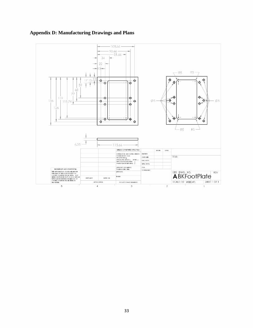
Appendix D: Manufacturing Drawings and Plans
33

34

35

36

37

38

39

40

41

42

43

44

45

Appendix E: Individual Ethical Design and Environmental Impact Statements Abby Crane Ethical Design The goal of our project is to ultimately help validate Pedestrian Crash Avoidance and Mitigation systems in future vehicles. We hope this will decrease the number of pedestrian collisions and increase public trust in automated vehicles. The use of this project emphasizes on the safety of pedestrians, thus it is important that this prototype accurately resembles a person. Simulating a realistic scenario is vital in the precision of the sensors in the process of testing.
Our design emphasized incorporating individual arm and leg motions to accurately represent the motion of person walking. However, our design does not account for the numerous types of non-ideal situations. These include a person with their hands in their pockets (no arm motion), a person walking and texting, a person running (more vigorous arm and leg motion), a person on a skateboard or bike (atypical body motion), a person wearing a large winter jacket (concealed arm/leg motion) and many other everyday scenarios.
This product should increase pedestrian safety, but by limiting the design to a very specific range in size and motion, it brings into question whether or not the sensors will pick up on anything else other than something that looks like the average adult male walking across the street with distinct arm and leg motion. The avoidance systems need to be able to sense people of all ages, shapes, and sizes in various situations.
Environmental Impact When going through the materials available to us from the previous semesters work, we noticed that many of the components came from overseas. This was done because the components were a lot cheaper in comparison to components made stateside. Since we had a lot of materials available to us already, we were able to splurge on higher quality components made in the US. This cuts down on overall transportation of materials.
We were also able to re-use a lot of the materials such as the aluminum T-stock, brakes, Arduinos and circuit board components, drive shafts, bearings, fixtures, and miscellaneous hardware. At end of use phase, it is important to dispose of the materials properly. Aluminum is easy to recycle and/or re-purpose for other design teams. Additionally, the torso is now made of Delrin (a type of acetal), which can be easily recycled as well. Electrical components such as motors, batteries, circuit boards will need to be disposed of correctly and carefully. We switched our batteries from lead acid to NiMH, thus safer to use and easier to dispose of since NiMH is less toxic than lead acid.
Manufacturing our parts required significant amount of machining and energy. Since our product isn’t going to be mass-produced, it is not as much of a concern but we still took this into consideration. We wanted to cut down on the amount of manufacturing by reducing the time to make each part, so we used a water jet to cut out the torso frame and ankle plate’s pieces.
46

Brendan Kawar Ethical Design The overall scope of this project aims to improve transportation safety and protect human life. Ethically, the idea behind the mechanized pedestrian is positive, meets legal requirements, and is driven by good human morals. However, when designing the mannequin, our team faced a few minor ethical challenges.
An ethical challenge was raised when taking into consideration the accuracy of the mannequin’s human resemblance. We felt that if our mannequin failed to correctly model human walking motion, it would wrongly “train” cars in distinguishing between humans and inanimate objects. If the software in these cars were manufactured and used as a standard for pedestrian detection, would we feel confident that it would avoid injuring people? This thought process led us to focus on the arm and leg mechanism to ensure that it met the requirements outlined by Dr. Sayer and Prof. Peng.
Other ethical concerns involved the safety of the people moving, operating, or testing the mannequin. We designed the mechanized pedestrian to be electrically and mechanically safe around those using it. Wire harnesses and electrical connections had to be properly soldered and insulated to prevent shortages or human contact. They also had to be shielded from any precipitation that could potentially start an electrical fire. Any sharp edges or pinching points were carefully considered to prevent injuring anyone re-setting or moving the pedestrian. All protruding edges were carefully filed down and moving parts were designed without any potential pinching points. Additional space was left in the design for proximity sensors or motor switches in the case that the MTC found a need for them.
Environmental Impact Our team took steps in reducing the ecological footprint of our project and took any environmental impacts under consideration. One of the biggest differences we were able to make over the previous ME 450 team was the use of parts purchased from Asia. Buying locally made and manufactured parts decreased the delivery distance, reducing the carbon footprint from transportation.
Another difference we made was the transition from lead acid batteries to nickel-metal hydride batteries. Lead acid batteries contain sulfuric acid and harmful amounts of lead; a toxic metal that can cause adverse health effects and is harmful to the environment if improperly disposed. Nickel metal hydride batteries do not contain the harmful materials found in lead acid batteries.
A big environmental concern our team faced is the disposal of the mechanized pedestrian at the end of its lifecycle. The motors, circuit boards, and sensors need to be properly recycled and can be disposed of in various recycling locations throughout Ann Arbor. The aluminum can either be recycled or re-used in the GGBrown machine shop. Another concern was the amount of energy used in the manufacturing of our components, either through a lathe, mill, or water jet. In order to reduce energy consumption, our team carefully evaluated our manufacturing plans to ensure that we did not need to use the machinery more than necessary.
47

Calvin Wang Ethical Design Since the mechanized pedestrian will be used to test Pedestrian Crash Avoidance/Mitigation systems in automated vehicles, it is important that it reflects the characteristics of a human pedestrian. Consequences of failing to meet the human resemblance requirement include producing faulty vehicles that can potentially hit human pedestrians during operation.
In our design process, we considered this ethics aspect of the project and gave high priority to the human resemblance performance. Specifically, we insisted to have separate feet base instead of having a single large base which would be easier to produce and power efficient to operate. Despite the advantages of the single base design, it does not have sufficient human appearance resemblance performance. Another design we implemented to improve human resemblance is the walking pattern. We designed the walking pattern to reflect a human walking motion by keeping the torso at constant speed instead of simply moving step by step. This adds complexity to our programming, but we considered it necessary.
Another ethics consideration is the safety of the product. The mannequin should not harm the user. In our design, we don’t include any sharp corners or edges to prevent cutting the user. All the electronic components are either placed inside a plastic housing or covered with insulation materials to avoid electrical shocks.
Environmental Impact Our product will not be in mass production, so it does not have significant environmental impacts. Nevertheless, we considered the environmental factor during out design and manufacture process.
We reused as many parts as possible from the old prototype, including all our aluminum T-stock for the frame and most of the electronic components. Since aluminum production is power intensive, using less aluminum saves energy. This reduces the environmental impact of our project’s manufacturing. We reduced the weight our mannequin. This lowers its power consumption during operation, because less mass is being driven.
At the end of the product life, most of the parts can be recycled. The main material we used are aluminum and Delrin. Aluminum can be easily recycled, and Delrin is thermoplastic, which can also be melted and recycled. We switched from lead acid batteries to nickel-metal hydride batteries, which contain less toxic material and have less environmental impact.
48

Seth Gable
Ethical Statement Since the goal of this project is to design a mechanism that will be used to test safety features, it is very important for it to allow for effective testing. In our case, this means that the mannequin must resemble a human closely enough that a sensor detecting it as human would also detect a real human as human. Some aspects of human resemblance (e.g. mimicking skin’s radar reflectivity or creating fully jointed limbs) are beyond the scope of this project and thus were not considered.
It must be noted that this mannequin cannot fully simulate all potential vehicle-pedestrian collision situations since it has been built to a set of dimensions based on the average adult male. While, in principle, things might be thought to scale well, it is worth noting that women, children and those men significantly above or below average height might not be properly represented and sensors built using this system might inadvertently be better at detecting people near the size of this average adult male.
The ASME code of ethics for mechanical engineers states, as the first fundamental principle that engineers “us[e] their knowledge and skill for the enhancement of human welfare.” The central goal of this project is to help increase the safety of vehicles through the addition of automated braking systems to decrease the frequency of vehicle-pedestrian collisions. We have kept this goal in mind during the design process and, in doing so have sought to uphold this fundamental principle of engineering ethics.
Environmental Statement In constructing the mannequin, we considered the environmental impact of the parts going into building it. One large consideration was the lead-acid batteries used in the previous design, which we replaced with more environmentally friendly nickel-metal hydride batteries, which do not contain lead and have no other highly toxic materials. The lead-acid batteries used previously can be recycled to prevent them from releasing toxins into the environment. We also chose to repurpose some parts previously used for the mannequin, such as the aluminum frame for the torso, which was used to make the new foot frame. Finally, we sought to order parts from American suppliers to avoid shipping overseas.
The polyoxymethylene (POM) and aluminum used for the frame are both recyclable, allowing for us to reduce waste when the mannequin reaches the end of its useful life by recycling most of the material used to make it. Aluminum can be recycled indefinitely and POM shows little change in properties over several recyclings.
The use of self-driving vehicles has the potential to reduce the environmental impact of transportation and while the immediate focus of this project is on testing automated braking systems, self-driving vehicles are a logical future step for the sensor technology that allows cars to detect obstacles. The way in which cars are driven can significantly affect the energy usage – e.g., frequent acceleration and deceleration will tend to decrease energy efficiency. Automated vehicles have the potential to ensure that vehicles are driven in the most efficient way.
49

12.0 ACKKNOWLEDGEMENTS
Team 13 would like to give special thanks to the sponsors, Huei Peng and Jim Sawyer of the University of Michigan Mobility Transformation Center. Additional thanks to Brent Gillespie for guidance and Charlie, John, and Toby for assistance in the manufacturing process. A special thanks to fellow classmates for the helpful suggestions and advice. 13.0 REFERENCES [1] National Highway Traffic Safety Administration (2013, August). “Traffic Safety Facts” Retrieved at: http://www-nrd.nhtsa.dot.gov/Pubs/811748.pdf Jan 24, 2015. [2] Bruce, Chris. (2015, January). “NHTSA adding automatic braking to recommended safety tech list” Retrieved at: http://www.autoblog.com/2015/01/25/nhtsa-automatic-braking-recommended-safety-list/ Jan 25, 2015
[3] Yi, C., Chien, S., Brink, J., Chen, Y., “Development of Equipment to Evaluate Pre-Collision Systems for Pedestrians”13-0221, Indiana University-Purdue University Indianapolis and Toyota Motor Sales, Indiana.
[4] Ford Motor Company (2014, October) “New Ford Pre-Collision Assist with Pedestrian Detection Technology May Help Drivers Avoid Some Frontal Crashes” Retrieved at: https://media.ford.com/content/fordmedia/fna/us/en/news/2014/10/23/new-ford-pre-collision-assist-with-pedestrian-detection.html Jan 24, 2015.
[5] Carpenter, M. G., Feldmann, M., Moury, M. T., Skvarce, J. R., Struck, M., Zwicky T. D., & Kiger, S. M. (2013, July). “Objective tests for forward-looking pedestrian crash avoidance/mitigation systems: annual report” (Report No. DOT HS 811 793). Washington, DC: National Highway Traffic Safety Administration. [6] Ahlstrom, V., & Longo, K. (2003). “Human Factors Design Standard” (HF-STD-001). Atlantic City International Airport, NJ: Federal Aviation Administration William J. Hughes Technical Center. [7] US Department of Transportation (2014, October). “Lane Width” Retrieved at: http://safety.fhwa.dot.gov/geometric/pubs/mitigationstrategies/chapter3/3_lanewidth.cfm Jan 24, 2015 [8] The Robot Market Place, “AmpFlow P40-250-P Pancake Motor Performance Chart” Retrieved at: http://www.robotmarketplace.com/products/0-P40-250-P.html
50

BIOS
Abby Crane I grew up in East Lansing, with my high school across the street from Michigan State University. I’m considered the traitor of the family for coming to the University of Michigan. My childhood consisted of Legos and K’Nex so mechanical engineering was a natural path for me to take. In my free time I like to play soccer, golf and music, and hang out with my friends and family. In the future I hope to work as a product design and development engineer.
Brendan Kawar My name is Brendan Kawar and I grew up outside of Chicago, IL. I am really interested in the automotive industry and its development, which led me to take on this design project. In the future, I hope to work with an automotive company in product design or manufacturing. When I’m not studying, I’m usually watching Michigan sports or spending time with friends. Calvin Wang My name is Calvin Wang and I grew up in both Germany and China. Currently, I am a senior in a dual degree program of Mechanical Engineering at the University of Michigan and Electrical and Computer Engineering at Shanghai Jiao Tong University. In my spare time, I like music and movies. My short-term plan is to continue my study in graduate school to deepen my knowledge and experience.
Seth Gable I was born and raised in Mashpee, Massachusetts and came to Michigan to study mechanical engineering. For the past 3 years, I have lived at Sojourner Truth Cooperative House, where I served as president during 2014 and am currently a maintenance manager. When not working, studying or fixing things at Truth House, I enjoy taking absurdly long walks.
51