Mechanical characterisation of porcine rectus sheath under 34 ...
10
XML-IS Our reference: BM 6571 P-authorquery-vx AUTHOR QUERY FORM Journal: BM Please e-mail or fax your responses and any corrections to: Article Number: 6571 E-mail: [email protected] Fax: +44 1392 285878 Dear Author, Please check your proof carefully and mark all corrections at the appropriate place in the proof (e.g., by using on-screen annotation in the PDF file) or compile them in a separate list. Note: if you opt to annotate the file with software other than Adobe Reader then please also highlight the appropriate place in the PDF file. To ensure fast publication of your paper please return your corrections within 48 hours. For correction or revision of any artwork, please consult http://www.elsevier.com/artworkinstructions. Any queries or remarks that have arisen during the processing of your manuscript are listed below and highlighted by flags in the proof. Click on the Q link to go to the location in the proof. Location in article Query / Remark: click on the Q link to go Please insert your reply or correction at the corresponding line in the proof Q1 Please confirm that given names and surnames have been identified correctly and are presented in the desired order. Q2 Please check the edit(s) made in the author’s affiliation “a” and correct if necessary. Q3 Keywords have been taken from the transmittal form. Please check and correct if necessary. Q4 “Moerman, 2013” has been changed to “Moerman et al., 2013” as per the reference list. Please confirm. Q5 Please check the sponsor name and correct if necessary. Irish Research Council, Ireland. Q6 Year has been added for the bibliography in reference “Boldo et al.”. Please check and correct if necessary. Q7 Please provide the place of publication for the bibliography in reference “Egan et al., 2009; Netter, 2006”. Q8 Fig. 8 has been submitted as colour image; however, the caption has been reworded to ensure that it is meaningful when your article is reproduced both in colour and in black and white. Please check and correct if necessary. Thank you for your assistance. Please check this box or indicate your approval if you have no corrections to make to the PDF file Z QBX
Transcript of Mechanical characterisation of porcine rectus sheath under 34 ...

XML-IS
Our reference: BM 6571 P-authorquery-vx
AUTHOR QUERY FORM
Journal: BM
Please e-mail or fax your responses and any corrections to:
Article Number: 6571
E-mail: [email protected]
Fax: +44 1392 285878
Dear Author,
Please check your proof carefully and mark all corrections at the appropriate place in the proof (e.g., by using on-screen annotation in
the PDF file) or compile them in a separate list. Note: if you opt to annotate the file with software other than Adobe Reader then please
also highlight the appropriate place in the PDF file. To ensure fast publication of your paper please return your corrections within 48
hours.
For correction or revision of any artwork, please consult http://www.elsevier.com/artworkinstructions.
Any queries or remarks that have arisen during the processing of your manuscript are listed below and highlighted by flags in the
proof. Click on the Q link to go to the location in the proof.
Location in
article
Query / Remark: click on the Q link to go
Please insert your reply or correction at the corresponding line in the proof
Q1 Please confirm that given names and surnames have been identified correctly and are presented in the desired order.
Q2 Please check the edit(s) made in the author’s affiliation “a” and correct if necessary.
Q3 Keywords have been taken from the transmittal form. Please check and correct if necessary.
Q4 “Moerman, 2013” has been changed to “Moerman et al., 2013” as per the reference list. Please confirm.
Q5 Please check the sponsor name and correct if necessary. Irish Research Council, Ireland.
Q6 Year has been added for the bibliography in reference “Boldo et al.”. Please check and correct if necessary.
Q7 Please provide the place of publication for the bibliography in reference “Egan et al., 2009; Netter, 2006”.
Q8 Fig. 8 has been submitted as colour image; however, the caption has been reworded to ensure that it is meaningful
when your article is reproduced both in colour and in black and white. Please check and correct if necessary.
Thank you for your assistance.
Please check this box or indicate your approvalif you have no corrections to make to the PDF file ZQBX

Mechanical characterisation of porcine rectus sheath under 34 uniaxialand biaxial tension
Mathew Lyons a,n, Des C. Winter b,c, Ciaran K. Simms aQ1
a Trinity Centre for Bioengineering, Department of Mechanical and Manufacturing Engineering, Trinity College, Parsons Building, College Green,Dublin 2, Irelandb Department of Surgery, St. Vincent's University Hospital, Elm Park, Dublin 4, Irelandc School of Medicine and Medical Science, University College Dublin, Belfield, Dublin 4, Ireland
a r t i c l e i n f o
Article history:Accepted 1 March 2014
KeywordsQ3 :Rectus sheathIntra-abdominal pressureUniaxial tensionBiaxial tensionFeBio model
a b s t r a c t
Incisional hernia development is a significant complication after laparoscopic abdominal surgery. Intra-abdominal pressure (IAP) is known to initiate the extrusion of intestines through the abdominal wall, butthere is limited data on the mechanics of IAP generation and the structural properties of rectus sheath.This paper presents an explanation of the mechanics of IAP development, a study of the uniaxial andbiaxial tensile properties of porcine rectus sheath, and a simple computational investigation of thetissue. Analysis using Laplace's law showed a circumferential stress in the abdominal wall of approx.1.1 MPa due to an IAP of 11 kPa, commonly seen during coughing. Uniaxial and biaxial tensile tests wereconducted on samples of porcine rectus sheath to characterise the stress–stretch responses of the tissue.Under uniaxial tension, fibre direction samples failed on average at a stress of 4.5 MPa at a stretch of 1.07while cross-fibre samples failed at a stress of 1.6 MPa under a stretch of 1.29. Under equi-biaxial tension,failure occurred at 1.6 MPa with the fibre direction stretching to only 1.02 while the cross-fibre directionstretched to 1.13. Uniaxial and biaxial stress–stretch plots are presented allowing detailed modelling ofthe tissue either in silico or in a surrogate material. An FeBio computational model of the tissue ispresented using a combination of an Ogden and an exponential power law model to represent thematrix and fibres respectively. The structural properties of porcine rectus sheath have been characterisedand add to the small set of human data in the literature with which it may be possible to developmethods to reduce the incidence of incisional hernia development.
& 2014 Published by Elsevier Ltd.
1. Introduction
Hernia development at wound sites after laparoscopic surgeryhas a prevalence rate of 1–3% (Boldo et al., 2006; Bowrey et al.,2001; Comajuncosas et al., 2011; Kadar et al., 1993; Tonouchi et al.,2004). The biomechanical driver behind hernia formation isevidently elevated intra-abdominal pressure (IAP), though thishas not been proven. The rectus sheath, a fibrous layer encom-passing the aponeurosis of the lateral abdominal muscles andenveloping the rectus abdominis muscle, is often implicated inhernia formation. However, there is surprisingly no literature onthe mechanical environment that generates IAP and thus nofundamental understanding of the stress states during herniaformation in the rectus sheath. There is also limited data on thestructural properties of rectus sheath, with varying protocols and
conflicting results (Ben Abdelounis et al., 2013; Martins et al.,2012; Rath et al., 1997). Rath et al. studied human rectus sheath inuniaxial tension but only reported failure stress and elongation.Martins et al. measured uniaxial stress–strain behaviour in humantissue in both fibre and cross-fibre directions, but reported largescatter with stresses between 2.5 and 20 MPa and failure stretchesup to 2.6 which seem doubtful. Statistical tests compared fibre andcross-fibre orientations, effects of BMI, and gender, but the samplesizes were small. Ben Abdelounis et al. recently examined theeffect of loading rate on the fibre direction response of humantissue in uniaxial tension. These authors also used an image basedstrain measure to address slippage at the tissue grip interfacewhich may account for some of the findings of Martins et al.However, their sample size was also small. The aims of this paperare therefore to analyse the loading environment in the abdominalwall, to characterise the tensile structural properties of the porcinerectus sheath using appropriate mechanical tests and to evaluatewhether a fibre reinforced computational material model canadequately replicate the observed experimental behaviour.
123456789
101112131415161718192021222324252627282930313233343536373839404142434445464748495051525354555657585960616263646566
Contents lists available at ScienceDirect
journal homepage: www.elsevier.com/locate/jbiomechwww.JBiomech.com
Journal of Biomechanics
http://dx.doi.org/10.1016/j.jbiomech.2014.03.0090021-9290/& 2014 Published by Elsevier Ltd.
n Corresponding authorQ2 . Tel.: þ353 879 935 447.E-mail addresses: [email protected] (M. Lyons),
[email protected] (D.C. Winter), [email protected] (C.K. Simms).
Please cite this article as: Lyons, M., et al., Mechanical characterisation of porcine rectus sheath under 34 uniaxial and biaxial tension.Journal of Biomechanics (2014), http://dx.doi.org/10.1016/j.jbiomech.2014.03.009i
Journal of Biomechanics ∎ (∎∎∎∎) ∎∎∎–∎∎∎
Original Text
Environment and behaviour
Original Text
Intra‐Abdominal pressure
Original Text
givenname
Original Text
surname
Original Text
givenname
Original Text
surname
Original Text
givenname
Original Text
surname
Original Text
Intra‐Abdominal
Original Text
stress‐stretch
Original Text
stress‐stretch
Original Text
1‐3%
Original Text
Intra‐Abdominal Pressure
Original Text
stress‐strain
Original Text
2.5–20
Original Text
Please confirm that given names and surnames have been identified correctly and are presented in the desired order.
Original Text
Please check the edit(s) made in the author\'s affiliation “a” and correct if necessary.
Original Text
Keywords have been taken from the transmittal form. Please check and correct if necessary.

2. Methods
2.1. The loading environment in the abdominal wall under IAP
IAP is generated through the action of the diaphragm and the abdominalmuscles. During quiet breathing, the abdominal muscles are inactive (Campbell andGreen, 1953) and contraction of the diaphragm reduces the craniocaudal diameterof the abdominal cavity and the IAP causes the dorsoventral diameter to increasepassively (Fig. 1(a)). This results in a minimal variation of IAP during normalbreathing of ca. 1 kPa (Malbrain et al., 2004; Sanchez et al., 2001; Sugerman et al.,1997). From Eq. (1), modelling the abdomen as a cylinder and assuming a radius of200 mm and an abdominal wall thickness of 2 cm (Sandler et al., 2010) (Fig. 1(a))the circumferential stress in the abdominal wall during breathing would be around10 kPa.
s¼ Prt: ð1Þ
In contrast, in an abdominal straining manoeuver the muscles of the abdominalwall contract and the diaphragm is then lowered, significantly reducing the volumeof the abdominal cavity. Approximating the cavity as an elliptical hemi-cylinder,the volume is
12 Lπr1r2 : ð2Þ
Using CT scanning, Duez et al. (2009) found the dimensions of the abdomen aslength: 341 mm, R1: 282 mm and R2: 104 mm which equates to a volume of 15.7 Lusing Eq. (2). Talasz et al. (2011) used MRI to evaluate the change in thesedimensions during coughing and found the length decreased to 304 mm, R1remained the same and R2 reduced to 94.5 mm giving a new, reduced volume of12.7 L.
Applying Boyle's law (PV¼k), assuming the abdomen was sealed and gas filled,a reduction in volume of 3 L (19%) would create a 19% increase in pressure. Given aresting IAP of 1 kPa this would generate an IAP of only 1.19 kPa during coughing,
much less than the average of 11 kPa reported (Cobb et al., 2005). However, withonly 115 ml of gas in the abdomen at rest (Bedell et al., 1956), blood must beexpelled from the abdomen via the venous and arterial networks to permit thisvolume reduction. Central venous pressure is approximately 2 kPa (Egan et al.,2009) but blood can only flow proximally through the venous network due tovalves. Diastolic blood pressure is approximately 10.5 kPa (Kshirsagar et al., 2006),and thus to expel blood via the arterial network, the IAP must exceed this.
Since contracting the abdominal muscles reduces the abdominal circumfer-ence, the transversalis fascia and peritoneum should not be under tension as theydo not act in series with the muscles (Fig. 1(b)). However, contraction of theinternal and external oblique muscles and the transverse abdominis would resultload the anterior and posterior rectus sheath and the linea alba (Fig. 1(b)).Application of Eq. (1) shows that an IAP of 11 kPa in an abdominal cavity of radius200 mm and thickness 2 mm (Martins et al., 2012; Song et al., 2006) would yield anaverage circumferential stress in the abdominal wall of 1.1 MPa. Defects, caused byabdominal surgery, would be particularly stressed in this configuration.
This preliminary analysis has shown that the biomechanics of abdominal wallloading during high IAP is complex. For future physical and computationalmodelling of the abdominal wall for wound closure analysis, it is of interest toestablish the stress–strain relationship of the rectus sheath for stresses of the orderof megaPascals. Furthermore, during periods of increased IAP the stress in thecross-fibre direction is likely to be non-negligible, and the biaxial tensile behaviourof the rectus sheath is therefore also of interest. Accordingly, mechanical testing inthese modes was performed and is reported next.
2.2. Physical tests
Twenty porcine abdominal walls were sourced from a local abattoir. All pigswere aged 26–28 weeks and all females were nulligravida. Animals were slaugh-tered and dissected in the abattoir as per their procedures where the abdominalwalls were harvested. They were subsequently kept frozen at �20 1C. Prior totesting, abdominal walls were defrosted at 571 1C for 40 h and dissected to isolate
123456789
101112131415161718192021222324252627282930313233343536373839404142434445464748495051525354555657585960616263646566
Fig. 1. Dimensions of the abdominal cavity, from Duez et al. (2009), (b) layers of the abdominal wall from Netter (2006) and (c) posterior view of a porcine belly showingfibre and cross-fibre directions.
M. Lyons et al. / Journal of Biomechanics ∎ (∎∎∎∎) ∎∎∎–∎∎∎2
Please cite this article as: Lyons, M., et al., Mechanical characterisation of porcine rectus sheath under 34 uniaxial and biaxial tension.Journal of Biomechanics (2014), http://dx.doi.org/10.1016/j.jbiomech.2014.03.009i
Original Text
)--
Original Text
Loading Environment
Original Text
Abdominal Wall
Original Text
Talasz et al., 2011
Original Text
stress strain
Original Text
megapascals.
Original Text
Tests
Original Text
5
Original Text
hours

the anterior rectus sheath. In all tests, a high definition Samsung HMX-QF20camera (Samsung Electronics Co., Gyeonggi-Do, Korea) recorded the sampledeformation at 2 fps.
2.2.1. UniaxialTissue was dissected into fibre direction and cross-fibre direction specimens
(Fig. 1(c)). Rectangular specimens 12–20 mm width and 16–66 mm in length werecut. Samples were labelled and stored in phosphate buffered saline solution (PBS)until immediately prior to tensile testing. Sixteen fibre direction and 16 cross-fibredirection samples were tested.
A jig was developed to improve alignment of specimens in the grips (Fig. 2).Grips were covered in grade P60 sandpaper. To prevent tissue damage duringgripping, grip bolts were tightened using a torque wrench to 0.2 N m, as this wasfound empirically to minimise both slippage (grips too loose) and tissue damage(grips too tight).
The width, thickness and mass of each sample were recorded prior to gripping.After gripping, the grip to grip distance (characteristic length) of the tissue wasmeasured and recorded. A grid of 6 dot markers was applied to the centre of thesample for strain analysis (Fig. 2(b)). Samples were tested under displacementcontrolled uniaxial tensile loading in a Zwick Roell Z005 machine (Zwick/RoellGmbH Ulm, Germany). A preload equal to the weight of the sample was appliedand samples were stretched until failure (420% drop in applied force) at 10% of thecharacteristic length per minute to minimise viscoelastic effects.
Custom Matlab code (Takaza et al., 2013a) was used to calculate strain from themarker motion. The engineering stress was calculated from the applied force andthe original CSA. Average stress/stretch curves preserving the overall shape ofindividual tests for fibre and cross-fibre samples were generated.
(1) Each curve was divided into the same predetermined number of discretepoints.
(2) Points were numbered from 1 to n, with shorter curves having a higher densityof points.
(3) The stress and stretch at each point was averaged over all of the curves.
An additional 0.1 MPa preload to reduce the scatter in the results was appliedto overcome challenges in identifying the unstrained sample length. This preloadrepresents only 2–5% of the maximum stress applied to the samples.
2.2.2. BiaxialA custom bladed punch was used to cut square samples 39.5 mm�39.5 mm,
and a custom gripping jig was used to ensure equal placement of four fish hooks (at11 mm spacing) to grip along each edge of the sample (Fig. 3(a) and (b)).
A custom designed equi-force biaxial testing rig (Prendergast et al., 2003)(Fig. 3(c)) was used to apply equal tensile force to each of the four sides of the
square specimen using a simple wire and pulley system connected to a Zwick RoellZ005 (Zwick/Roell GmbH Ulm, Germany) testing machine. A pre-load was appliedto straighten the sample (approx. 3 N). Crosshead movement was displacementcontrolled, at a rate of 5 mm/min, and the custom rig moved to maintain equalforce on each side of the specimen despite different strains. A speckle pattern ofdrawing ink was applied to the tissue for subsequent strain analysis using digitalimage correlation (DIC) (Fig. 3(c)).
DIC was conducted using freely available MATLAB code (Eberl, 2010). Thismethod of strain analysis was used as the fish hooks caused local deformation ofthe tissue and also left corner regions unstressed. Force measurements wererecorded by the Zwick machine. Average stress/stretch plots were created for thefibre and cross-fibre direction in the same way as for uniaxial samples.
2.3. Statistical analysis
Time history control charts with 3s limits were used to prevent time biasaffecting the results (operator experience etc.). Normal probability plots weregenerated for the average tissue stretch and stress at failure to ensure theassumption of normality applied. ANOVAs were generated to ensure that thevariation between pig bellies was not significantly different from samples withineach belly. A Student's T test was conducted to compare the stress/stretch responseof fibre and cross-fibre specimens.
2.4. Computational modelling
Computational modelling of the uniaxial and biaxial tests was performed usingFeBio (Maas et al., 2012) to assess the ability of a fibre reinforced hyper-elasticmodel to reproduce the observed experimental results. A first order Ogden modelrepresented the tissue matrix and an exponential power law represented the fibres(Maas and Weiss, 2013), with the following strain energies (Ψ).
Ogden
Ψ ¼ ∑N
i ¼ 1
cim2
i
ðλ ~mi1 þλ
~mi2 þλ
~mi3 �3ÞþUðJÞ ð3Þ
where λi are the deviatoric stretches, c and m are material constants and U(J)represents the volumetric component, where J is the determinant of the deforma-tion gradient tensor. A first order Odgen model was used. The volumetriccomponent is computed based on the bulk modulus.
Exponential� power law
Ψ ¼ ξ
αβðeαð~I n �1Þβ �1Þ ð4Þ
123456789
101112131415161718192021222324252627282930313233343536373839404142434445464748495051525354555657585960616263646566
Fig. 2. (a) Uniaxial gripping jig and (b) uniaxial gripped sample in Zwick Machine. Matlab dot tracking software identifies regions A, B, C and D in the direction of the appliedstretch and regions a, b and c in the orthogonal direction. Stretch was calculated in each of these regions and averaged to give global vertical (applied) and horizontal(response) stretch values.
M. Lyons et al. / Journal of Biomechanics ∎ (∎∎∎∎) ∎∎∎–∎∎∎ 3
Please cite this article as: Lyons, M., et al., Mechanical characterisation of porcine rectus sheath under 34 uniaxial and biaxial tension.Journal of Biomechanics (2014), http://dx.doi.org/10.1016/j.jbiomech.2014.03.009i
Original Text
Gripping Jig--
Original Text
Uniaxial Gripped Sample--
Original Text
Phosphate Buffered Saline Solution
Original Text
sixteen
Original Text
Nm,
Original Text
was
Original Text
minimize
Original Text
Engineering
Original Text
generated:
Original Text
Original Text
Analysis

where α and β are material constants and ξ is a measure of the fibre modulus and ~I nis the square of the fibre stretch.
A custom Matlab codeQ4 (Moerman et al., 2013; Takaza et al., 2013b) was used tofind the optimummaterial parameters for these models in both the fibre and cross-fibre directions for uniaxial testing. The optimisation algorithm used the Matlabfminsearch function to minimise the sum of squared difference between theexperimental and predicted force displacement data with a tolerance of 0.0001.A nominal bulk modulus of 10 was used in all cases, with a higher value havingminimal effect on results but yielding longer solution times.
Two uniaxial simulations were performed for each of the fibre and cross-fibredirections to assess the influence of tissue gripping on the mid-sample stretch–stress relationship. Ideal geometries matching the average geometries of fibre andcross-fibre specimens respectively were created and meshed using 3200 hexahe-dral elements. In the simple uniaxial case, nodes at one end of the sample wereconstrained from translating in the z direction (see Fig. 6 for coordinate system)and from rotating. Nodes at the other end of the sample were also constrained fromrotating and prescribed a vertical displacement at 10% of specimen length perminute to stretch the sample, similar to the physical tests. The stress–stretchresponse of a central element was exported. In a second simulation, nodes at bothends of the sample, in the region under the grips, were constrained fromtranslating in the z direction and from rotating. Equal compression of 20% in they direction was applied to both sides of the tissue in the region of the grips tosimulate gripping. This represented the approx. 40% reduction in thicknessmeasured in the region of the grips in the experimental samples. The finalconfiguration after gripping was taken as the initial configuration for subsequentuniaxial tension. Nodes at one end, in the region of the bottom grip wereconstrained from translating in the z direction and from rotating. Nodes at theother end, in the region of the top grip, were constrained from rotating and a
prescribed displacement of 10% per minute was applied in the z direction. Thestress–stretch response of the same central element was exported for comparisonpurposes.
Subsequently, a biaxial simulation was conducted using the average materialparameters from the individual simulations of each of the uniaxial tests and theresults were compared to the average experimental biaxial results.
3. Results
3.1. Uniaxial
Fig. 4 shows the fibre and cross-fibre direction stress–stretchcurves and the average curve for each direction.
3.2. Biaxial
Fig. 5 shows biaxial stress–stretch plots for all the samples.
3.3. Computational modelling
The average and the ranges of the predicted model parametersfrom fitting to the uniaxial data are presented in Table 1.
123456789
101112131415161718192021222324252627282930313233343536373839404142434445464748495051525354555657585960616263646566
Fig. 3. Biaxial gripping jig: (a) one edge of the jig with hooks, (b) the complete jig and (c) the gripped sample in the equi-force biaxial testing rig.
M. Lyons et al. / Journal of Biomechanics ∎ (∎∎∎∎) ∎∎∎–∎∎∎4
Please cite this article as: Lyons, M., et al., Mechanical characterisation of porcine rectus sheath under 34 uniaxial and biaxial tension.Journal of Biomechanics (2014), http://dx.doi.org/10.1016/j.jbiomech.2014.03.009i
Original Text
Gripping Jig.--
Original Text
One--
Original Text
hooks--
Original Text
2.4.1Ogden(3)Ψ=∑i=1Ncimi2(λ1mi+λ2mi+λ3mi-3)+U(J)where λi are the deviatoric stretches, c and m are material constants and U(J) represents the volumetric component, where J is the determinant of the deformation gradient tensor. A first order Odgen model was used. The volumetric component is computed based on the bulk modulus.
Original Text
2.4.2Exponential-Power Law(4)Ψ=ξαβ(eα(In-1)β-1)where α, β are material constants and ξ is a measure of the fibre modulus and In is the square of the fibre stretch.A custom Matlab code (Moerman et al., 2013; Takaza et al., 2013b) was used to find the optimum material parameters for these models in both the fibre and cross-fibre directions for uniaxial testing. The optimisation algorithm used the Matlab fminsearch function to minimize the sum of squared difference between the experimental and predicted force displacement data with a tolerance of 0.0001. A nominal bulk modulus of 10 was used in all cases, with a higher value having minimal effect on results but yielding longer solution times.Two uniaxial simulations were performed for each of the fibre and cross-fibre directions to assess the influence of tissue gripping on the mid-sample stretch-stress relationship. Ideal geometries matching the average geometries of fibre and cross-fibre specimens respectively were created and meshed using 3200 hexahedral elements. In the simple uniaxial case, nodes at one end of the sample were constrained from translating in the z direction (see Fig. 6 for coordinate system) and from rotating. Nodes at the other end of the sample were also constrained from rotating and prescribed a vertical displacement at 10% of specimen length per minute to stretch the sample, similar to the physical tests. The stress-stretch response of a central element was exported. In a second simulation, nodes at both ends of the sample, in the region under the grips, were constrained from translating in the z direction and from rotating. Equal compression of 20% in the y direction was applied to both sides of the tissue in the region of the grips to simulate gripping. This represented the approx. 40% reduction in thickness measured in the region of the grips in the experimental samples. The final configuration after gripping was taken as the initial configuration for subsequent uniaxial tension. Nodes at one end, in the region of the bottom grip, were constrained from translating in the z direction and from rotating. Nodes at the other end, in the region of the top grip, were constrained from rotating and a prescribed displacement of 10% per minute was applied in the z direction. The stress-stretch response of the same central element was exported for comparison purposes.Subsequently, a biaxial simulation was conducted using the average material parameters from the individual simulations of each of the uniaxial tests and the results were compared to the average experimental biaxial results.
Original Text
stress‐stretch
Original Text
stress‐stretch
Original Text
“Moerman, 2013” has been changed to “Moerman et al., 2013” as per the reference list. Please confirm.

The goodness of fit of the computational stress–stretch data tothe experimental data is shown in Table 1 in terms of R2
and sum of squared difference. Plots of the fit for a fibre andcross-fibre uniaxial sample and a biaxial sample are shownin Fig. 6 along with images of undeformed and deformedsamples.
4. Discussion
4.1. Fundamental pressure analysis
The stress state in the abdominal wall during periods of raisedIAP such as coughing is not discussed in the literature. Using
123456789
101112131415161718192021222324252627282930313233343536373839404142434445464748495051525354555657585960616263646566
Fig. 4. Stress–stretch plots for all fibre direction (N¼16) and cross-fibre direction (N¼16) samples in uniaxial tension.
Fig. 5. Biaxial stress–stretch plots for all samples (N¼14).
Table 1FeBio material model parameters and average goodness of fit of computational data to experimental data for all samples.
First order Ogden model
C M
Mean Range Mean Range
0.057 0.016–0.119 8.203 1–14.01
Exponential power law modelBeta Ksi
Mean Range Mean Range
2 2–2 0.3424 0.162–0.864
Longitudinal samples Transverse samplesR2 SSQD R2 SSQD
98.1% 0.391 98.1% 0.391
M. Lyons et al. / Journal of Biomechanics ∎ (∎∎∎∎) ∎∎∎–∎∎∎ 5
Please cite this article as: Lyons, M., et al., Mechanical characterisation of porcine rectus sheath under 34 uniaxial and biaxial tension.Journal of Biomechanics (2014), http://dx.doi.org/10.1016/j.jbiomech.2014.03.009i
Original Text
Material Model Parameters--
Original Text
Order--
Original Text
Model--
Original Text
Power Law Model--
Original Text
Samples--
Original Text
Samples--
Original Text
Pressure Analysis

simple mechanics, some geometric measurements and preliminaryassumptions, the preliminary analysis presented here has been usedto determine an estimated stress in the rectus sheath as a result ofintra-abdominal pressure. For coughing, the circumferential stress islikely to be of the order of 1 MPa. The cross-fibre stress is moredifficult to estimate, but is likely to be non-negligible, and thebiaxial behaviour of rectus sheath is therefore of interest. The skinand fat are not considered in this analysis. While this may beappropriate due to the compliant and elastic nature of the skin andthe very low toughness and strength of the fat, experimentalverification is still required. Furthermore, biological variations couldsignificantly affect the stress state. These variations could benatural, or as a result of surgery or other co-morbidities. Theseresults provide a useful context for hernia modelling, but should besupported by future experimental or finite element modelling.
This biomechanical analysis shows stresses in the order ofmegaPascals can be expected in the rectus sheath during abdom-inal straining manoeuvres such as coughing, and the biaxial aswell as the uniaxial behaviour are of interest.
4.2. Physical tests
Despite the importance of the rectus sheath in IAP loading, there isuncertainty regarding the structural properties of rectus sheath andthis was the motivation to characterise the stress–stretch response ofthe rectus sheath in uniaxial and biaxial tension. Uniaxial tensile tests(16 cross-fibre and 16 along fibre) and biaxial tests (14) wereconducted on porcine rectus sheath samples. There was noticeablevariation in the stretch in each region of the samples, and the averagegraphical stretch was found to be less than the machine stress in allcases indicating that, despite best efforts, there was some slippage atthe grips. This further highlights the necessity to use graphical strainanalysis methods, unlike what was done previously (Martins et al.,
2012; Rath et al., 1997). The stress–stretch response for each sample inboth directions is shown in Fig. 4. The variability can mostly beattributed to biological variation between the samples. ANOVAshowed that the variation between samples was more significant thatthe variation between pig bellies used (P¼0.18). It is clear that there isa large difference between the fibre and cross-fibre direction samples,and this was statistically significant at the 99.9% level (Po0.001).Breaking stretch values for the cross-fibre samples were much larger(1.3) than for the fibre direction samples (1.07) and the respectiveultimate stress values were much lower (1.6 MPa vs. 4.5 MPa).
Comparisons with the data from Rath et al. and Martins et al.are shown in Fig. 7(a). Rath et al. only reported failure stress andstrain, thus straight lines for their data are shown. Results fromMartins et al. seem doubtful due to the significant variation, thevery high stress and the large elongation reported. Given thecomplications experienced in the current study with samplegripping, necessitating the use of a torque wrench and the use ofimage-based strain measurement, it seems likely that slippageoccurred in the Martins et al. tests. Both Rath et al. and Martinset al. relied on the grip to grip separation to determine strain,which is known to be problematic (Takaza et al., 2013a). Further-more, the variation in reported stiffness from the three authors,which is likely to be partially due to variations in age, BMI andparity, makes direct comparison difficult with the presentedresults from healthy, young, nulligravid pigs.
Nonetheless, Fig. 7(b) compares current results with recent datafrom Ben Abdelounis et al. evaluating the uniaxial stress–strainresponse of human rectus sheath in the cross-fibre direction. BenAbdelounis et al. also used image based strain and, coupled with thesimilarity in the average responses observed, the comparison increasesconfidence in the current results. Furthermore, the comparisonsuggests that the uniaxial behaviour of porcine and human rectussheath is similar.
123456789
101112131415161718192021222324252627282930313233343536373839404142434445464748495051525354555657585960616263646566
Fig. 6. Typical fit of FeBio stress–stretch results to experimental uniaxial stress–stretch results in the (a) cross-fibre, (b) fibre directions and (c) biaxial tensile simulations.(d) Typical undeformed and deformed sample for an ungripped (left) and gripped (right) case.
M. Lyons et al. / Journal of Biomechanics ∎ (∎∎∎∎) ∎∎∎–∎∎∎6
Please cite this article as: Lyons, M., et al., Mechanical characterisation of porcine rectus sheath under 34 uniaxial and biaxial tension.Journal of Biomechanics (2014), http://dx.doi.org/10.1016/j.jbiomech.2014.03.009i
Original Text
stress‐stretch--
Original Text
stress‐stretch--
Original Text
cross‐fibre and --
Original Text
shows a typical undefomed --
Original Text
Tests
Original Text
stress‐strain
Due to the unusual behaviour of the tissue, it was not possibleto quantify the Poisson's ratio in our experiments. During gripping,the tissue in contact with the grips spread in the horizontaldirection under the compression of the grips.
Under biaxial loading, the samples stretched uniformly acrosstheir width in both directions. Fig. 5 shows the fibre direction wassignificantly stiffer than the cross-fibre direction. In some casescontraction occurred in the fibre direction while elongating in thecross-fibre direction under biaxial tensile loading (see left-handside of Fig. 5). It is believed this is due to a large differencebetween the fibre and cross-fibre direction stiffnesses, and this iscorroborated by an analysis based on linear elastic transverseisotropy where the stress–strain relationship is
εL
εT
εT'εLT
εLT'εTT'
26666666664
37777777775
¼
1EL
�ϑTLEL
�ϑTLET
0 0 0
�ϑLTEL
1ET
�ϑTT'ET
0 0 0
�ϑLTEL
�ϑTT'ET
1ET
0 0 0
0 0 0 1GTT'
0 0
0 0 0 0 1GLT
0
0 0 0 0 0 1GLT
2666666666666664
3777777777777775
sL
sT
sT'sLT
sLT'
sTT'
266666666664
377777777775
: ð5Þ
Eq. (5) was used to predict strains under equibiaxial tensileloading for a range of fibre and cross-fibre direction stiffnesses
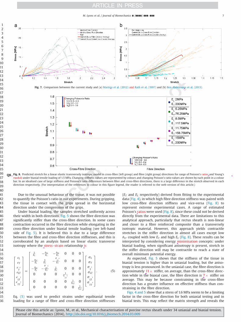
(ET and EL respectively) derived from fitting to the experimentaldata (Fig. 4), in which high fibre direction stiffness was paired withlow cross-fibre direction stiffness and vice-versa (Fig. 8) torepresent extreme experimental cases. A range of estimatedPoisson's ratios were used (Fig. 8), since these could not be deriveddirectly from the experimental data. There are limitations to thisanalytical approach, particularly that rectus sheath is non-linearand closer to a fibre reinforced composite than a transverselyisotropic material. However, this approach yields contractilestretches in the stiffer direction in almost all cases except lowϑLT coupled with low ET and high EL (Fig. 8). These results can beinterpreted by considering energy minimisation concepts: underbiaxial loading, when significant anisotropy is present, stretch inthe stiffer direction will may be contractile to reach a state ofoverall minimum potential energy.
As expected, Fig. 5 shows that the stiffness of the tissue inbiaxial tension is higher than in uniaxial loading, but the aniso-tropy is less pronounced. In the uniaxial case, the fibre direction isapproximately 11� stiffer, on average, than the cross-fibre direc-tion while in the biaxial case, the fibre direction is 7� stiffer onaverage. This may be because constraining in the cross-fibredirection has a greater influence on effective stiffness than con-straining in the fibre direction.
Figs. 4 and 5 show that a stress of 1.6 MPa seems to be a limitingfactor in the cross-fibre direction for both uniaxial testing and inbiaxial tests. This may reflect the matrix strength and reveals the
123456789
101112131415161718192021222324252627282930313233343536373839404142434445464748495051525354555657585960616263646566
Fig. 8. Predicted stretch for a linearQ8 elastic transversely isotropic model in cross-fibre (left group) and fibre (right group) directions for range of Poisson's ratios and Young'smoduli under biaxial tensile loading of 1.5 MPa. Changing stiffness values are represented by colours and changing Poisson's ratio values are shown by each point in a colourbar. In an idealised case of large stiffness and Poisson's ratio differences between fibre and cross-fibre directions, there is a large difference in the stretch observed in eachdirection respectively. (For interpretation of the references to colour in this figure legend, the reader is referred to the web version of this article.)
Fig. 7. Comparison between the current study and (a) Martins et al. (2012) and Rath et al. (1997) and (b) Ben Abdelounis et al. (2013).
M. Lyons et al. / Journal of Biomechanics ∎ (∎∎∎∎) ∎∎∎–∎∎∎ 7
Please cite this article as: Lyons, M., et al., Mechanical characterisation of porcine rectus sheath under 34 uniaxial and biaxial tension.Journal of Biomechanics (2014), http://dx.doi.org/10.1016/j.jbiomech.2014.03.009i
Original Text
), --
Original Text
).--
Original Text
Ratios--
Original Text
Moduli--
Original Text
stress strain
Original Text
is:
Original Text
Ratios
Original Text
minimization
Original Text
11x
Original Text
7x
Original Text
Fig. 8 has been submitted as colour image; however, the caption has been reworded to ensure that it is meaningful when your article is reproduced both in colour and in black and white. Please check and correct if necessary.

importance of the fibre reinforcement in withstanding the stressesgreater than 1.6 MPa created by IAP.
Statistical tests showed no anomalies in the testing procedure.Control charts showed no time bias affecting the results andnormal probability plots showed normality in the results. ANOVAsrevealed that variation between pig bellies was not statisticallysignificantly different from variation within each belly.
4.3. Computational modelling
The Ogden model was a very good fit to the cross-fibredirection uniaxial experimental data, with high R2 (98%) coupledwith a low SSQD (0.391). The model for the fibre direction, whichincludes an uncoupled matrix represented by the Ogden modeland an exponential power law representing the fibres also had ahigh R2 (96%) and a SSQD of 18.1 (Fig. 6 and Table 1).
The fit for the biaxial simulation (Fig. 6) was not as good as forthe uniaxial optimisation, but it still captures the essential differ-ence in stiffness between the two directions. The material proper-ties were obtained from uniaxial optimisation and biaxial tensionwas applied. This did not account for any additional interactionsbetween the two load directions, and suggests a more complexmodel might be required.
As noted previously, during gripping the tissue under the gripsspread, creating a somewhat dog-bone shaped sample from asample that was originally rectangular. Upon application of uni-axial tension the tissue initially bulged in the lateral direction tore-create a rectangular specimen before beginning to narrow aswould be expected. As a result of this unusual movement of thetissue, accurate measurement of the horizontal stretch was notpossible in most cases, thus the Poisson's ratio could not bequantified. It is hypothesised that in the fibre direction case, thefibres become curved as a result of gripping. When tensile loadingis initiated, these fibres straighten out, causing the sample to bulgeoutwards. Once the fibres are straight, the tissue then can behaveas normal and contract in the unloaded direction. The FeBiosimulation with the average model parameters was used to assesshow this influenced the presented stress–stretch results. Fig. 9shows that gripping the tissue did not significantly affect the stressat the centre of the specimen, with differences less than 5% in bothload directions.
The fibre reinforced material model showed good potential tocapture the uniaxial elastic behaviour of the tissue. In the biaxialsimulations, the slopes the experimental curves is similar to theFeBio data, but the toe region is not well matched. This is possiblydue to differences in preload application in the experimental andnumerical simulations.
To the authors' knowledge, this study is the first to discuss therelationship between IAP and the loading of the abdominal wall.
The response of porcine rectus sheath to uniaxial and equi-biaxialtension has been characterised and has been shown to be similarto the response of human rectus sheath in the uniaxial case.Further work will see the development of a surrogate material toreplicate rectus sheath in an experimental environment for devel-opment of surgical devices.
Conflict of interest statement
The authors declare no conflict of interest.
Acknowledgements
The authors would Q5like to acknowledge the assistance ofMr. Michael Takaza and Dr. Kevin Moerman with the FeBio Matlaboptimisation routines. This study was funded by the Irish ResearchCouncil EMBARK Scheme.
References
Bedell, G.N., Marshall, R., DuBois, A.B., Harris, J.H., 1956. Measurement of thevolume of gas in the gastrointestinal tract. Values in normal subjects andambulatory patients. J. Clin. Investig. 35, 336–345.
Ben Abdelounis, H., Nicolle, S., Otténio, M., Beillas, P., Mitton, D., 2013. Effect of twoloading rates on the elasticity of the human anterior rectus sheath. J. Mech.Behav. Biomed. Mater. 20, 1–5.
Boldo, E., de Lucia, G.P., Aracil, J.P., Martin, F., Escrig, J., Martinez, D., Miralles, J.M.,Armelles, A., 2006. Trocar site hernia after laparoscopic ventral hernia Q6repair.In: Proceedings of the 16th World Congress of the International Association ofSurgeons and Gastroenterologists. Madrid.
Bowrey, D.J., Blom, D., Crookes, P.F., Bremner, C.G., Johansson, J.L.M., Lord, R.V.,Hagen, J.A., DeMeester, S.R., DeMeester, T.R., Peters, J.H., 2001. Risk factors andthe prevalence of trocar site herniation after laparoscopic fundoplication. Surg.Endosc. 15, 663–666.
Campbell, E., Green, J., 1953. The variations in intra-abdominal pressure and theactivity of the abdominal muscles during breathing; a study in man. J. Physiol.122, 282.
Cobb, W.S., Burns, J.M., Kercher, K.W., Matthews, B.D., James Norton, H., ToddHeniford, B., 2005. Normal Intraabdominal pressure in healthy adults. J. Surg.Res. 129, 231–235.
Comajuncosas, J., Vallverdu, H., Orbeal, R., Pares, D., 2011. Trocar site incisionalhernia in laparoscopic surgery. Cir. Esp. 89, 72–76.
Duez, A., Cotte, E., Glehen, O., Cotton, F., Bakrin, N., 2009. Appraisal of peritonealcavity's capacity in order to assess the pharmacology of liquid chemotherapysolution in hyperthermic intraperitoneal chemotherapy. Surg. Radiol. Anat. 31,573–578.
Eberl, C., 2010. Digital Image Correlation and Tracking. Mathworks.Egan, D.F., Wilkins, R.L., Stoller, J.K., Kacmarek, R.M., 2009. Egan's Fundamentals of
Respiratory Q7Care. MosbyKadar, N., Reich, H., Liu, C.Y., Manko, G.F., Gimpelson, R., 1993. Incisional hernias
after major laparoscopic gynecologic procedures. Am. J. Obstet. Gynecol. 168,1493–1495.
Kshirsagar, A.V., Carpenter, M., Bang, H., Wyatt, S.B., Colindres, R.E., 2006. Bloodpressure usually considered normal is associated with an elevated risk ofcardiovascular disease. Am. J. Med. 119, 133–141.
123456789
101112131415161718192021222324252627282930313233343536373839404142434445464748495051525354555657585960616263646566
Fig. 9. FeBio stress–stretch plots for a (a) cross-fibre and (b) fibre direction sample in a gripping and non-gripping scenario.
M. Lyons et al. / Journal of Biomechanics ∎ (∎∎∎∎) ∎∎∎–∎∎∎8
Please cite this article as: Lyons, M., et al., Mechanical characterisation of porcine rectus sheath under 34 uniaxial and biaxial tension.Journal of Biomechanics (2014), http://dx.doi.org/10.1016/j.jbiomech.2014.03.009i
Original Text
stress‐stretch--
Original Text
stress‐stretch
Original Text
Interest Statement
Original Text
.
Original Text
J Clin Invest.
Original Text
J Mech Behav Biomed
Original Text
Year
Original Text
Surg
Original Text
The Journal of Physiology
Original Text
Pressure
Original Text
Healthy Adults
Original Text
J Surg
Original Text
[Trocar
Original Text
surgery]
Original Text
Cir Espan.
Original Text
Surg Radiol
Original Text
C.EberlDigital Image Correlation and TrackingMathworks2010
Original Text
Am J Obstet
Original Text
Am J
Original Text
Please check the sponsor name and correct if necessary. Irish Research Council, Ireland.
Original Text
Year has been added for the bibliography in reference “Boldo et al.”. Please check and correct if necessary.
Original Text
Please provide the place of publication for the bibliography in reference “Egan et al., 2009; Netter, 2006”.

Maas, S., Weiss, J., 2013. FeBio Theory Manual.Maas, S.A., Ellis, B.J., Ateshian, G.A., Weiss, J.A., 2012. FEBio: finite elements for
biomechanics. J. Biomech. Eng. 134, 011005.Malbrain, M.N.G., Chiumello, D., Pelosi, P., Wilmer, A., Brienza, N., Malcangi, V.,
Bihari, D., Innes, R., Cohen, J., Singer, P., Japiassu, A., Kurtop, E., De Keulenaer, B.,Daelemans, R., Del Turco, M., Cosimini, P., Ranieri, M., Jacquet, L., Laterre, P.-F.,Gattinoni, L., 2004. Prevalence of intra-abdominal hypertension in critically illpatients: a multicentre epidemiological study. Intensiv. Care Med. 30, 822–829.
Martins, P., Peña, E., Jorge, R.M.N., Santos, A., Santos, L., Mascarenhas, T., Calvo, B.,2012. Mechanical characterization and constitutive modelling of the damageprocess in rectus sheath. J. Mech. Behav. Biomed. Mater. 8, 111–122.
Moerman, K.M., Nederveen, A.J., Simms, C.K., 2013. Image Based Model Construc-tion, Boundary Condition Specification and Inverse FEA Control: A Basic MatlabToolkit for FeBio Computer Methods in Biomechanics and Biomedical Engi-neeering. Utah, Salt Lake.
Netter, F.H., 2006. Atlas of Human Anatomy. Saunders/Elsevier.Prendergast, P.J., Lally, C., Daly, S., Reid, A.J., Lee, T.C., Quinn, D., Dolan, F., 2003.
Analysis of prolapse in cardiovascular stents: a constitutive equation forvascular tissue and finite-element modelling. J. Biomech. Eng. 125, 692–699.
Rath, A.M., Zhang, J., Chevrel, J.P., 1997. The sheath of the rectus abdominis muscle:an anatomical and biomechanical study. Hernia 1, 139–142.
Sanchez, N.C., Tenofsky, P.L., Dort, J.M., Shen, L.Y., Helmer, S.D., Smith, R.S., 2001.What is normal intra-abdominal pressure? Am. Surg. 67, 243.
Sandler, G., Leishman, S., Branson, H., Buchan, C., Holland, A.J.A., 2010. Body wallthickness in adults and children – relevance to penetrating trauma. Injury 41,506–509.
Song, C., Alijani, A., Frank, T., Hanna, G., Cuschieri, A., 2006. Elasticity of the livingabdominal wall in laparoscopic surgery. J. Biomech. 39, 587–591.
Sugerman, H., Windsor, A., Bessos, M., Wolfe, L., 1997. Intra-abdominal pressure,sagittal abdominal diameter and obesity comorbidity. J. Intern. Med. 241,71–79.
Takaza, M., Moerman, K.M., Gindre, J., Lyons, G., Simms, C.K., 2013a. The anisotropicmechanical behaviour of passive skeletal muscle tissue subjected to largetensile strain. J. Mech. Behav. Biomed. Mater. 17, 209–220.
Takaza, M., Moerman, K.M., Simms, C.K., 2013b. Passive skeletal muscle response toimpact loading: experimental testing and inverse modelling. J. Mech. Behav.Biomed. Mater. 27, 214–225.
Talasz, H., Kremser, C., Kofler, M., Kalchschmid, E., Lechleitner, M., Rudisch, A., 2011.Phase-locked parallel movement of diaphragm and pelvic floor during breath-ing and coughing – a dynamic MRI investigation in healthy females. Int.Urogynecol. J. 22, 61–68.
Tonouchi, H., Ohmori, Y., Kobayashi, M., Kusunoki, M., 2004. Trocar site hernia.Arch. Surg. 139, 1248.
123456789
10111213141516171819
M. Lyons et al. / Journal of Biomechanics ∎ (∎∎∎∎) ∎∎∎–∎∎∎ 9
Please cite this article as: Lyons, M., et al., Mechanical characterisation of porcine rectus sheath under 34 uniaxial and biaxial tension.Journal of Biomechanics (2014), http://dx.doi.org/10.1016/j.jbiomech.2014.03.009i
Original Text
S.MaasJ.WeissFeBio Theory Manual2013
Original Text
J Biomech
Original Text
Intens
Original Text
J Mech Behav Biomed Mater
Original Text
human anatomy
Original Text
J Biomech Eng
Original Text
Normal Intra‐Abdominal Pressure?
Original Text
Am Surgeon
Original Text
children—Relevance
Original Text
J Biomech
Original Text
J Intern
Original Text
J Mech Behav Biomed Mater
Original Text
Experimental
Original Text
J Mech Behav Biomed Mater
Original Text
coughing—a
Original Text
Int Urogynecol