
Measurement of Pitching-Moment Derivatives for Aerofoils Oscillating...
38
.... X:.;., ¢._ 1, MINISTRY OF AVIATION R. & M. No. 3234 AERONAUTICAL RESEARCH COUNCIL REPORTS AND MEMORANDA Measurement of Pitching-Moment Derivatives for Aerofoils Oscillating in Two-Dimensional Supersonic Flow By C. SCRUTON, B.Se., L. WOODGATE, K. C. LAPWORTH, M.Se., Ph.D. and J. MAYBREY OF THE AERODYNAMICS DIVISION, N.P.L. LONDONt HER MAJESTY'S STATIONERY OFFICE 1962 FOURTEEN SHILLINGSNET f f
Transcript of Measurement of Pitching-Moment Derivatives for Aerofoils Oscillating...

. . . . X : . ; . , ¢._
1,
M I N I S T R Y O F A V I A T I O N
R. & M. No. 3234
AERONAUTICAL RESEARCH COUNCIL
REPORTS AND MEMORANDA
Measurement of Pitching-Moment Derivatives for Aerofoils Oscillating in Two-Dimensional
Supersonic Flow By C. SCRUTON, B.Se. , L. WOODGATE, K. C. LAPWORTH, M.Se., Ph.D.
and J. MAYBREY
OF T H E AERODYNAMICS DIVISION, N.P.L.
LONDONt HER MAJESTY'S STATIONERY OFFICE
1962
FOURTEEN SHILLINGS NET
f f

Measurement for Aerofoils
of Pitching-Moment Derivatives Oscillating in Two-Dimensional
Supersonic Flow By C. SCRUTON, B.Sc., L. WOODGATE, K. C. L A P W O R T H , M.Sc., Ph.D.
and J. MAYBREY
OF THE AERODYNAMICS DIVISION, N . P . L .
Reports and Memoranda No. 3234*
January, ±959
Summary. Pitching-moment derivatives have been measured by a free oscillation technique on two- dimensional aerofoils of double wedge section with thickness/chord ratios of 0.08, 0.12 and 0-16; and on an aerofoil of single wedge section of thickness/chord ratio 0.16. The Mach number ranged between 1" 37 and 2.43 and the axis position was varied over a wide range. The Reynolds numbers and the frequency parameters of the tests were less than 106 and 0.03 respectively. A few tests were made at incidence.
For some axis positions and low values of Mach number, negative values of the aerodynamic damping were found considerably in excess of those predicted by theory. Theories which take into account thickness effects correctly predicted the trends of the derivatives with changes in axis position and in Mach number, and also the axis position at which the damping changes from positive to negative. However, substantial differences in the numerical values were often found, particularly at the low Mach numbers and these are attributed in part to the detached bow-wave on the thicker wings at low Mach numbers and in part to the effects of the boundary layer and of flow separations.
1. Introduction. The experiments to be described form part of an investigation to provide
information of the aerodynamic loads acting on aerofoils and wings oscillating in supersonic flow.
Measurements on finite wings will be described in subsequent reports; the present report is
concerned only with measurements on aerofoils in two-dimensional flow. Previous experiments 1
made by Bratt and Chinneck using a 7½ per cent thick bi-convex aerofoil oscillating about t h e half-chord axis did not yield values in agreement with the Temple-Jahn theory 2 for thin aerofoils,
and failed to substantiate the region of negative values of the pitching-moment damping predicted
by this theory. The trends obtained were in somewhat better agreement with Collar's simple
extension of Ackeret's theory 8 for thin aerofoils from steady to unsteady motion and with the
theories developed by W . P. Jones 4, s for oscillating aerofoils of finite thickness. Further theories
in which thickness effects have been introduced and which are simpler to apply than those of Jones, are by Van Dyke 5 and by Lighthill 6, and these have been critically reviewed by Acum ~.
Previously issued as A.R.C. 20,650. Published with the permission of the Director, National Physical Laboratory.
In the tests described in the present report, pitching-moment derivatives were measured by the
free oscillation method. The influence of sectional thickness was determined by measurements on double wedge aerofoils of thickness/chord ratios 0.08, 0.12, and 0.16. Tests were also carried out with a single wedge aerofoil of 0.16 thickness/chord ratio. It was not considered to be practical to test thinner sections because the greater flexibility in bending might then permit undesirable
effects due to coupling of the pitching with bending motions of the aerofoil. The influence of axis
position for the range - 0.25 < h < 1.25 was investigated for all these aerofoils and a few experi-
ments on the effect of incidence were also made. The tests were carried out in the N.P.L. 11 in.
Supersonic Wind Tunnel which provides continuous flow in a working section 11 in. wide and
either 12 in. high for the range 1.4 < M < 1.7, or 14 in. high for the range 1.7 < M < 2.5.
The range of Reynolds number corresponding to this range of Mach number for the aerofoils of 2.5 in. chord was from 0.96 x 10⁶ to 0.62 x 10⁶. The frequency parameter was of the order of
0.02 for all the tests.
2. Basic Formulae and Method of Test. The aerodynamic moment acting on the aerofoil is expressed by
.///t = MoO + MoO. (1)
For simple harmonic motion of frequency co/2~r, Jd is expressed in terms of its non-dimensional
in-phase and out-of-phase components as
y
m 0 - ~
p V2c2s(mo + ivmo) 0 (2)
mo=
where o,c/V
Me/pV2c=s }
Mo/pVc3s . (3)
For the free oscillation technique used, the aerofoil was mounted on bearings which permitted only pitching motion against a spring constraint. Records were obtained of the decaying oscillations
of the system after it had been displaced from the equilibrium position and suddenly released.
The equation of motion is then
I0 + (K-Mo)O + (o-Mo)O = 0 (4) .
for whiCh a solution is
where 0 = 0oe~ t sin cot
K M0 t * - 2I
(5)
and
Hence a = - t*/.f.
K - M o = 2/./'8
- M e = I(o,2 + t ,2 )
(6)
(7)
2

and denoting values of quantities in vacuo (where M o = Mo = 0) by suffix 0,
- M o = 2I(f8-f08o) (8)
- M e = I { ( o02 + / x2) - (OOo~ +/Xo~)}. (9)
In practice it is found that/x 2 -/Xo2 ~ ~o 2 - c% 2,/~o 2 ~ ~oo2 , and may be neglected, so that
~7
- M o = . ~ ( f - f 0 ) ( f + f o ) . (10)
3. Description of Apparatus. The l/Vind Tunnel. The tests were carried out in the N.P.L.
Continuous Flow Supersonic Wind Tunnel which had a 12 in. x 11 in. working section for the
range 1.4 < M < 1.7 and a 14 in. x 11 in. section for the range 1.7 < M < 2.5. The tunnel
stagnation pressure could be reduced from one to about one-quarter of an atmosphere. A dry air
supply was available for controlling the humidity, and dry air was introduced into the tunnel both
before and during the run, the stagnation pressure being maintained at the required value by means
of extractor pumps. For the low values of the Mach number humidity effects became evident
when the fros} point was higher than - 9 deg F. Accordingly, experiments were only conducted when the frost point was - 15 deg F or less.
The Models and their Mountings. The models were machined from solid 'Leadloy' steel plate;
both ends of the plate remained rectangular in section to provide flanges for bolting the aerofoil
on to the oscillatory mountings. The aerofoils completely spanned the 11 in. tunnel and had a chord length of 2.5 in.
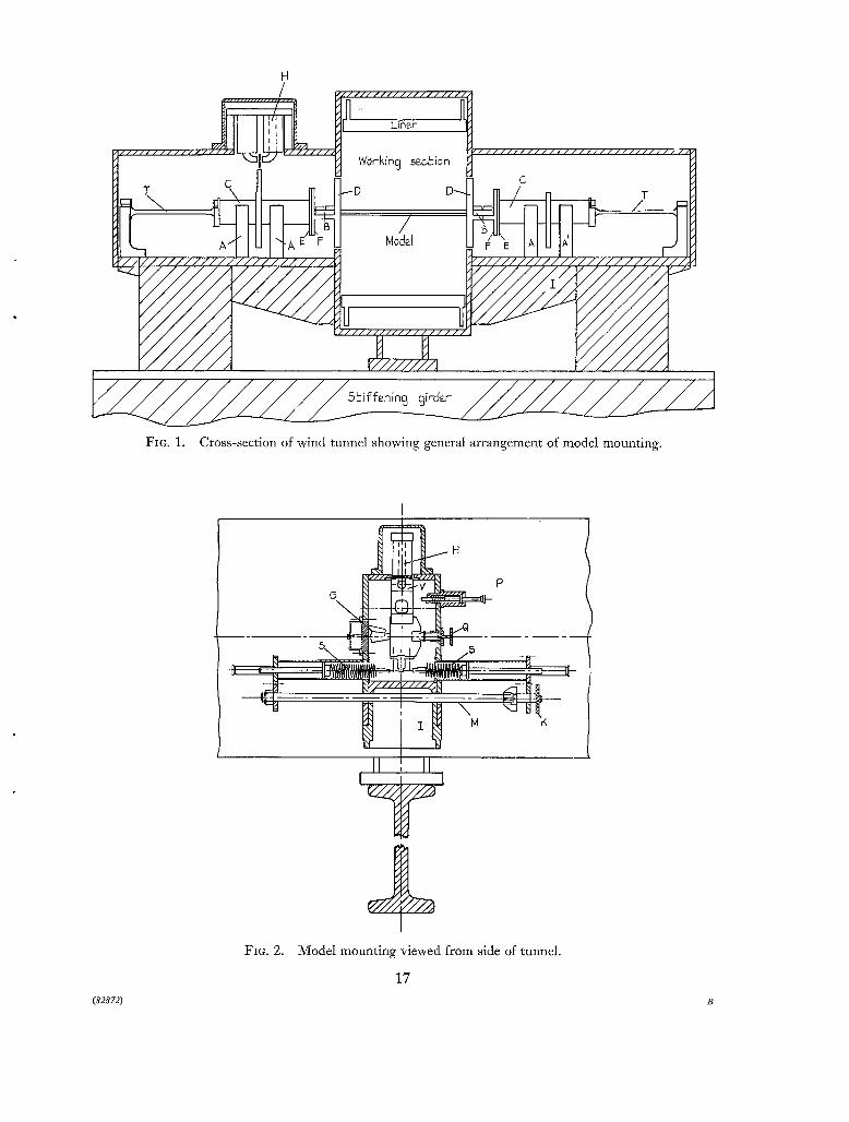
Diagrammatic sketches of the arrangement of the aerofoil and its mountings in the wind tunnel
are shown in Figs. 1 and 2 and a photograph of one Of the mountings is reproduced in Fig. 3.
Each mounting consisted of a stiff webbed bracket I fixed to the tunnel wall and which carried the
oscillating mechanism. A cylinder C was suspended on two sets of cross-spring bearings A and A'
which held the cylinder rigidly against all movements except rotation about its longitudinal axis. The rotation of the cylinder was constrained by the torque bar T. This arrangement ensured that
the mechanical damping of the oscillating system was very low. The inner end of the cylinder terminated in a circular plate E to which another circular plate F was fitted concentrically. The
aerofoil flange B could be bolted on to a flange on the latter plate in several fore and aft positions to give pitching axes of from - 0.25h to 1.25h in intervals of 0. 125h. The angle of incidence of the aerofoil could be set at intervals of one degree by rotating the inner circular plate F. With the model
a~ incidence there was an aerodynamic moment which tended to change the mean incidence.
Such changes were undesirable and were corrected by the incidence compensating spring arrange- ment shown in Fig. 2. For this purpose the rotation of the cylinder C was constrained by two
tensioned horizontal helical springs and incidence correction was achieved by rotating the knurled
head K operating a screw which increased the tension in one spring while decreasing it in the other.
The helical springs were contained within airtight brass sleeves P and Perspex sides were fitted to
the metal framework of the mounting to form an airtight box to prevent air leakage into the tunnel
which could otherwise take place through the gap between the tunnel walls and the disks D.
To allow for the required variation in the pitching axis it was necessary to make the disks of 6 in.
diameter. The gap between disk and tunnel wall was made very small and, with air leakage into
the tunnel prevented by the airtight boxes, it was considered that these gaps caused negligible interference to the flow inside the tunnel.
3 (82872) A. 2

The cylinder also carried fittings for limiting and for recording its motion. Mechanical stops
to the motion were provided by the adjustable clamp Q (Fig. 2) while eddy current damping, supplied by a copper vane V and electromagnet H, was automatically switched on when the amplitude
of oscillation reached a pre-set value. The condenser gauge G was used to record the motion.
The spring-loaded plunger P operated against an arm fixed to the rotating cylinder, and was used
to set the system in oscillation. The mountings on each side of the tunnel were similar and they were designed to be mounted
on the tunnel walls independently of each other. However, it was found that the inward flexing of the tunnel walls caused by the reduced internal pressure during the run sufficiently disturbed the alignment of the system to produce spurious apparatus damping. To reduce this effect to an acceptable amount the mountings were interconnected by a massive girder.
The Measuring and Recording Eqz@ment. The electronic apparatus for recording the oscillations, from which the logarithmic decrement of the amplitude and the frequency could be found by analysis,
is shown schematically in Fig. 4. The condenser gauge formed by vanes attached to the cylinder of one oscillating unit moved
between fixed vanes and the variation of capacity so produced modulated the frequency of a 1 Mc/s carrier signal. This signal was fed into a Southern Instruments F.NI. amplifier and discriminator which converted the frequency deviation into a voltage amplitude. This signal was then displayed on one beam of a double-beam oscilloscope. Pulses spaced at intervals of 0- 01 second were recorded by the other beam to form a time base. These timing pulses were derived from the N.P.L. standard frequency signal of 1,000 c.p.s, which was fed into a dekatron frequency divider. A continuously moving film camera was used to photograph the screen of the oscilloscope and to provide a record
of the decaying oscillations. After each experiment, calibration traces were also obtained on the film by displacing the cylinder
carrying the gauge through various known angles and recording the resulting steady displacements
of the oscilloscope beam.
4. Method of Test. Records of the decaying or growing oscillations of the aerofoil were obtained in wind using the equipment described in previous paragraph, and these were analysed in the usual way to obtain the values of the logarithmic decrement and the frequency. The electric stiffness was
obtained by a static experiment and the values of the apparatus damping and the in vacuo moment of inertia of the system were obtained from free oscillation tests carried out with the tunnel evacuated to nearly 1/4 atmospheric pressure. This was the minimum pressure attainable but tests at other higher pressures indicated that the apparatus damping was not very sensitive to tunnel pressure.
5. Res~tlts. For most test conditions it was found that the value of the damping derivative - mo was dependent on amplitude 0 and that, within the experimental accuracy available and the amplitude range of the test, the rate of variation - dmo/dO was constant. The rate itself varied widely with the test condition and both positive and negative values were obtained. Little variation of the
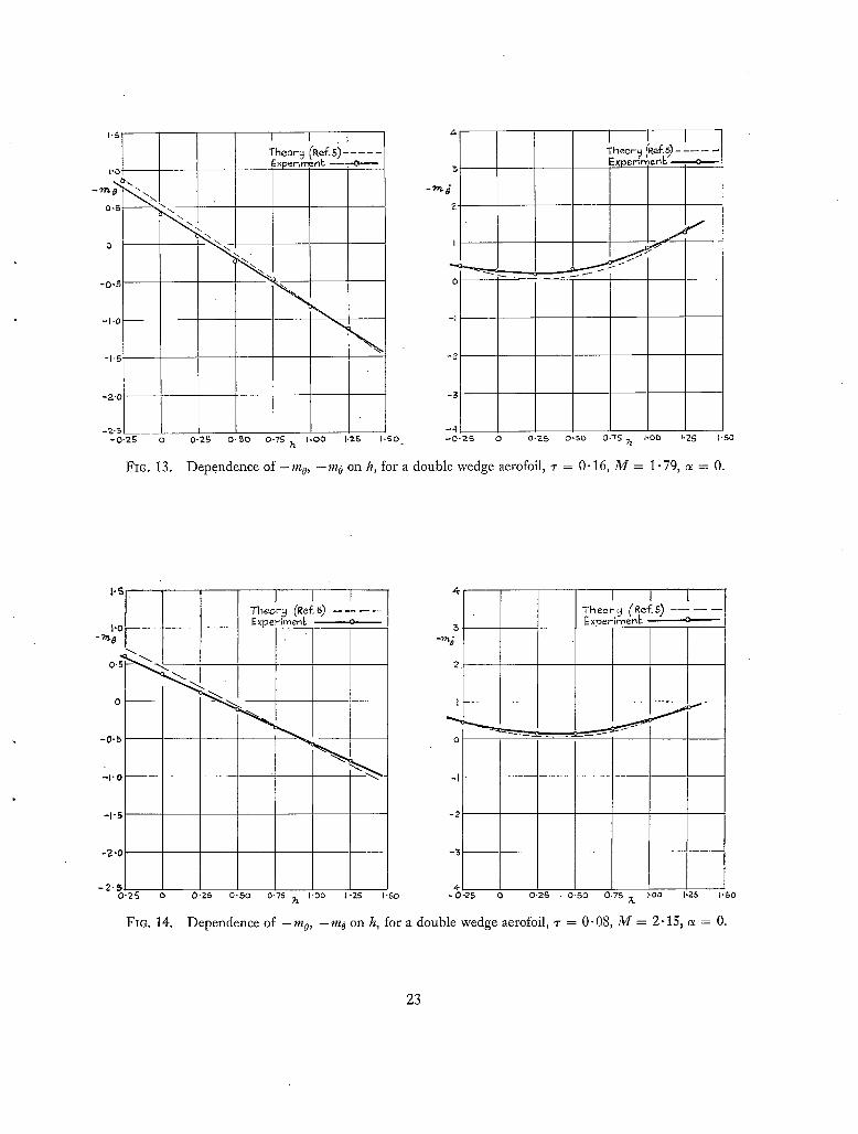
stiffness coefficient - m o with 0 was found. For convenience the experimental values quoted in the tables of results (Tables 1 to 8) refer to a standard amplitude of 0 = 0. 0175 radian and the value of - dmo/dO is given in the adjacent column. In the discussion of results which follows, and in the plots of the results given in Figs. 5 to 36, the values of the derivatives quoted refer to this standard amplitude. Unless specified otherwise the theoretical values have been computed by Van Dyke's theory 5. Figs. 5 to 19 inclusive give plots of the derivative values against h for the double wedge
4

aerofoils. For h = 0.25, 0.50 and 0.75, these results are also given in Figs. 20 to 25 as plots of
the derivatives against M. Further cross-plots of the results are given in Figs. 26 to 28 to show the
influence of thickness/chord ratio and the results of the measurements at incidence are plotted in
Figs. 29 to 31. Results for the single wedge aerofoil of 16 per cent thickness/chord ratio are plotted
in Figs. 32 to 36.
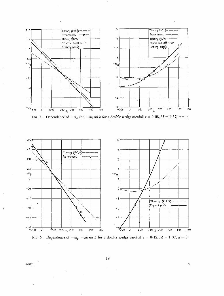
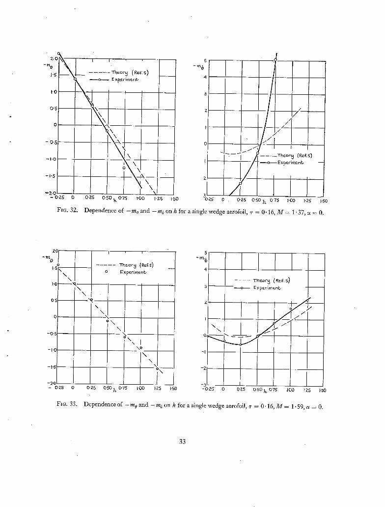
6. Discussion of the Results. (a) Variation o f - mo, - m 0 with h (see Figs. 5 to 19 and 32 to 36). For both the single and the double wedge aerofoils the experimentally determined values of - m o
and - mo show the same trends as those calculated from Van Dyke's theory a, but for the double wedge aerofoil the values of the derivatives found by theory and experiment often differ considerably.
These differences become very marked at low values of M and for thick aerofoils. Except for the lowest Much numbers the numerical agreement obtained between theory and experiment for the
16 per cent thick single wedge aerofoil is very good.
As is predicted by the theory, negative values of the aerodynamic damping were found for certain ranges of h at low values of M. The critical value of h bounding the region for instability appears to be predicted with fair accuracy by the theory. However, especially for the lowest value of Much number, M = 1.37, and the thicker aerofoils, the amount of negative damping (and of positive damping for the values of h for which - m0 was positive) was very much greater than calculated and, indeed, resulted in some very violent and rapidly growing oscillations of the
aerofoil which the eddy-current damping built into the system as a safety device was unable to control, and resort had to be made to mechanical stops.
The theory 5 used to calculate the derivatives is only valid when the bow wave is attached to the leading edge of the aerofoil, and bow wave detachment provides one possible reason for the large discrepancies found between experiment and theory at the low Much numbers. For M = 1.37,
the maximum angle through which the stream can be turned at the leading edge without the bow wave becoming detached is 8.6 degrees, whereas the half-wedge angles for the 8, 12 and 16 per cent double wedge aerofoils used in the tests were 4.6, 6.8 and 9.1 degrees respectively. When the
amplitude of oscillation is taken into account (a maximum of about 2 degrees) it appears that bow- wave detachment may have occurred, for all or part of the cycle of oscillation, with the 12 and . 16 per cent thick aerofoils, but not at all with the 8 per cent thick aerofoil. Bow wave detachment does not, therefore, adequately explain the large discrepancies found at M = 1.37 with the latter aerofoil, nor does it do so for the similar discrepancies observed with the 16 per cent aerofoil at M = 1.59. The theory is based on potential flow considerations, and hence further reasons for the
discrepancies may be sought in the effects of viscosity in promoting boundary layers and flow separations. The boundary layer permits pressure fluctuations from behind the trailing-edge shocks to travel upstream and thus to modify the pressure distribution over the aerofoil. This upstream
influence would be expectedto be less for the single than for the double wedge section so that, as was found in the experiments, the results would correspond more closely to those derived from a potential flow theory. The dependence of the derivative values on amplitude must also be attributed to viscoug effects. The suggestion was made that, in the presence of separated flow, the trailing edge of the aerofoil becomes inoperative, and hence that closer agreement might be obtained by comparisons of the measured values of the derivatives with values calculated for the double wedge section with the trailing-edge portion absent (see also Ref. 8). Mr. W. E. A. Acum carried out these calculations for various amounts of cut-off. In the present report the values thus calculated are
plotted only in Fig. 5 for a 40 per cent chord 'cut-off' from the trailing edge with M = 1.37 and
~- = 0.08. This result shows the general trends found for all values of M and ~-. For too, the cut-off produced a change of slope and aerodynamic centre which worsened the agreement with experiment
for low values of Mach number. For M = 2.43, however, the calculated and the experimental
curve coincided if 'cut-offs' of 15, 30 and 40 per cent were assumed for 7 = 0.08, 0.12 and 0.16
respectively. The effect on the damping, - too, was generally small for any reasonable amount of 'cut-off' and tended to increase the discrepancies between calculation and experiment.
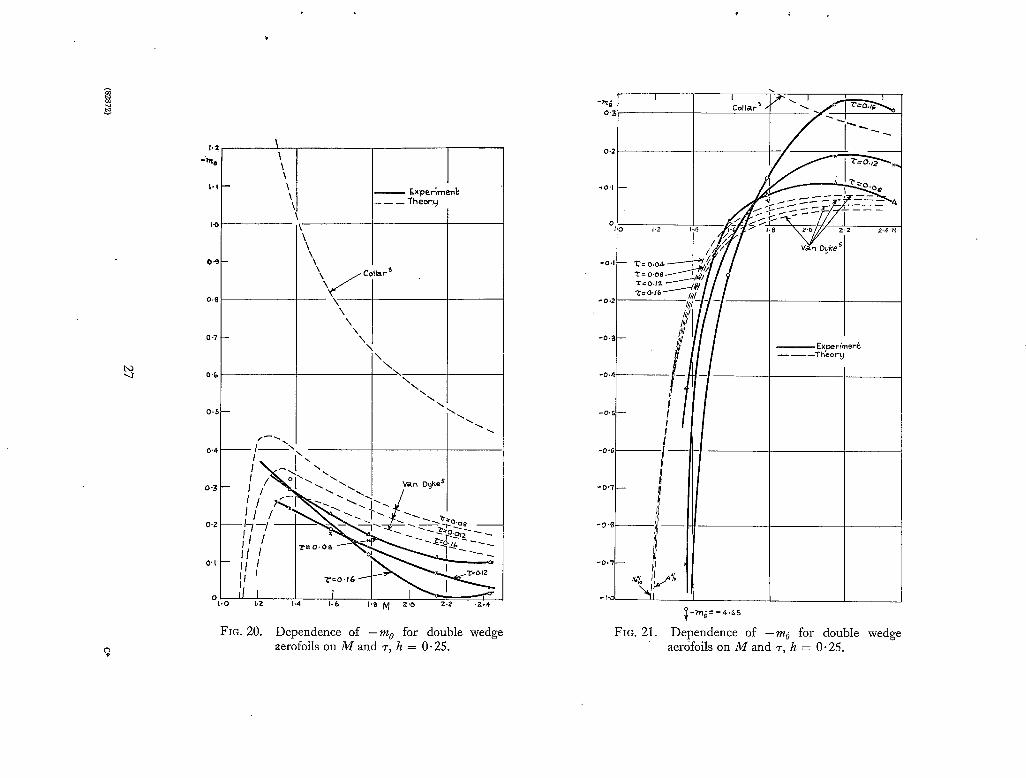
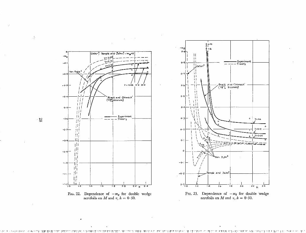
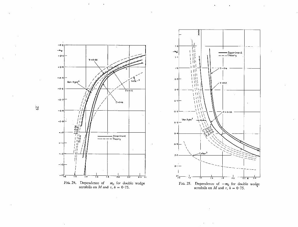
(b) Variation of - m o and - m o with M (Figs. 21 to 25). The plots of the derivatives against M
are given in Figs. 21 to 25 for h = 0.25, 0.50 and 0"75, and theoretical curves obtained by the theories of Collar ~, and Temple and Jahn 2, are included with those obtained by Van Dyke's theory 5.
These results show that Van Dyke's theory predicts the general trends of the variation with M but,
as noted in the previous paragraph, numerical agreement with experimental values is not good,
the latter values being arithmetically greater than those of theory. For h = 0.50 the experimental
results of the present repor t agree fairly well with those obtained experimentally by Bratt and
Chinneck 1 for a 7.5 per cent thick bi-convex aerofoil. For this axis position the values of the
damping derivatives calculated by Collar's theory were in somewhat better agreement 'with
experiment than the other theories, but this was not so for the other axis positions.
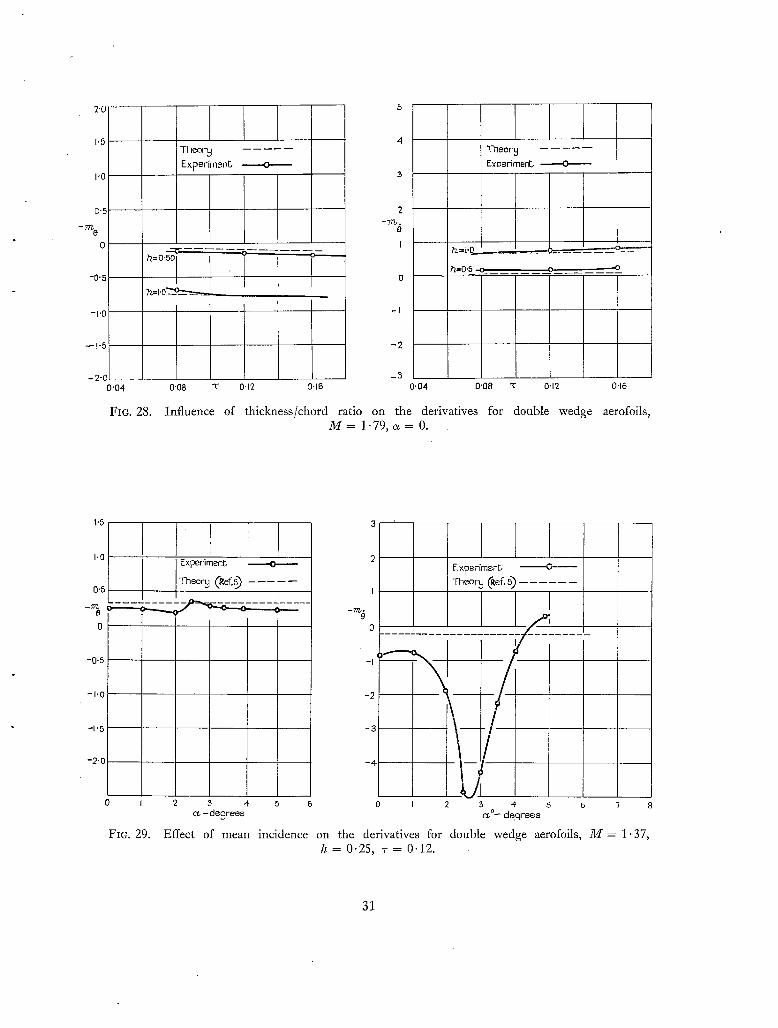
(c) Influence of derofoil Thickness (Figs. 26 to 28). The plots given in Figs. 26 to 28 have been chosen to illustrate the influence of aerofoil thickness. For the lowest value of Mach number,
the numerical values of the damping derivative showed a much more rapid increase with thickness than is predicted by theory. This effect was less marked for M = 1.59 and became progressively
less with increase of Mach number until at M = 2.43 only the slight increases with thickness predicted by theory were found.
(d) Effect of Incidence (Figs. 29 to 31). Tests at mean incidences other than zero were made only for M = 1.37 and 2-43. For the lower Mach number mean incidence had considerable effect on
the damping, increasing the positive damping found with h = 0.5 to a maximum at ~ = 3 degrees,
and similarly increasing the negative damping found at h = 0.25 to a maximum at ~ = 2.7 degrees.
For the latter axis position the damping became positive at about ~ = 5 degrees. These changes are
attributed to the bow-wave detachment and flow separation effects mentioned previously. They
disappeared at high Mach numbers, as was shown by the results for M = 2.43 given in Fig. 31.
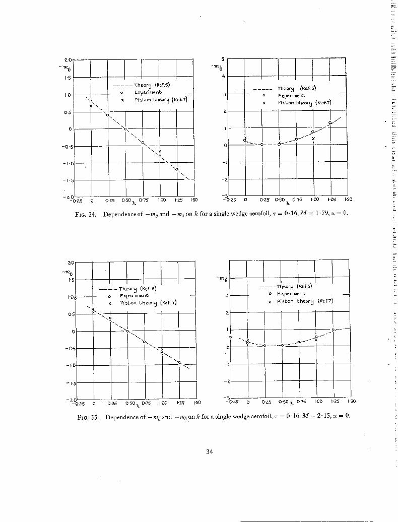
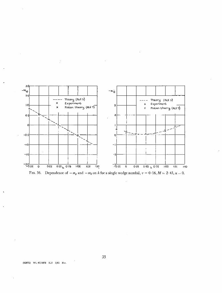
7. Values of the Derivatives obtained by Lighthill's Piston Theory. Values of the derivatives have
been calculated using piston theory 6 for the double wedge aerofoils at M = 2.43 and for the single
wedge aerofoils at M = 1.79, 2.15 and 2.43, and the results are plotted in Figs. 17 to 19 and in
Figs. 34 to 36 respectively. It will be seen that reasonable agreement with the calculated values l~y
the method of Ref. 5 was obtained at M = 2.43, and for a Mach number as low as 1.79 reasonably good agreement was found for the half-chord axis position.
8. Conclusions. (i) As suggested by theory the aerodynamic damping of the pitching oscillations of an aerofoil became negative for low Mach numbers and certain ranges of axis position.
(ii) The variation of the derivatives with axis position or with Mach number followed the same trend as those predicted by the Van Dyke theory 5 but the numerical values often differed considerably from those predicted by this theory. The differences were most marked for the thicker wings and
6
z
:7
' ' !_
Z:
?:
!_
' ~ 2_
t
at the lower Mach numbers. The axis position at .which the aerodynamic damping changed from positive to negative was predicted wlth fair accuracy by the theory. The numerical agreement with the theory increases with decrease of section thickness.
(iii) The detachment of the bow wave with the thicker wings at low Mach numbers produced large changes in the derivatives; (negative damping became more negative and positive damping more positive)and was partly the cause of some of the discrepancies found between theory and experiment. Other causes are attributed to the effects of the boundary layer and of flow separation.
(iv) Values of the derivatives for M = 2.43 calculated by piston theory showed reasonably good agreement with those obtained by Van Dyke's theory.
i
¢
M
V
P
C
$
I
(r
K
-M0
- - m 0
-M0
- - ~ ' t / 6
f
O3
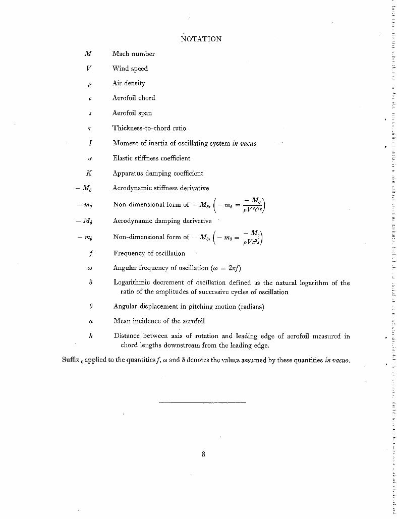
NOTATION
Mach number
Wind speed
Air density
Aerofoil chord
Aerofoil span
Thickness-to-chord ratio
Moment of inertia of oscillating system in vacuo
Elastic stiffness coefficient
Apparatus damping coefficient
Aerodynamic stiffness derivative
Non-dimensional form of - Mo, ( -
Aerodynamic damping derivative
/ - M o \ Non-dimensional form of - Mo, t - mo - ~ )
Frequency of oscillation
Angular frequency of oscillation (o3 = 27rf)
- M o
m° - pVYfids )
Logarithmic decrement of oscillation defined as the natural logarithm of the ratio of the amplitudes of successive cycles of oscillation
0 Angular displacement in pitching motion (radians)
a Mean incidence of the aerofoil
h Distance between axis of rotation and leading edge of aerofoil measured in chord lengths downstream from the leading edge.
Suffix 0 applied to the quantities f, o3 and ~ denotes the values assumed by these quantities in vacuo.
8

No. Author(s)
1 J .B. Bratt and A. Chinneck
2 G. Temple and H. A. Jahn
3 A.R. Collar . . . .
4 W.P. Jones . . . .
5 Milton D. Van Dyke . . . .
6 M.J . Lighthill . . . . . .
7 W . E . A . Acum . . . . . .
8 W. P. Jones and Sylvia W. Skan
REFERENCES
Title, etc.
Measurements of mid-chord pitching moment derivatives at high speeds.
A.R.C.R. & M. 2680. June, 1947.
Flutter at supersonic speeds: derivative coefficients for a thin aerofoil at zero incidence.
A.R.C.R. & M. 2140. April, 1945.
Resistance derivatives of flutter theory. Part II--Results for supersonic speeds.
A.R.C.R. & M. 2139. January, 1944.
The influence of thickness/chord ratio on supersonic derivatives for oscillating aerofoils.
A.R.C.R. & M. 2679. September, 1947.
Supersonic flow past oscillating airfoils including non-linear thickness effects.
N.A.C.A. Report 1183. 1954. Supersedes N.A.C.A. Tech. Note 2982. 1953.
Oscillating airfoils at high Mach number. J. Ae. Sci. Vol. 20. No. 6. pp. 402 to 406. June, 1953.
Note on the effect of thickness and aspect ratio on the damping of pitching oscillations of rectangular wings moving at super- sonic speeds.
A.R.C.C.P. 151. May, 1953.
Aerodynamic forces on bi-convex aerofoils oscillating in a supersonic airstream.
A.R.C.R. & M. 2749. August, 1951.
9
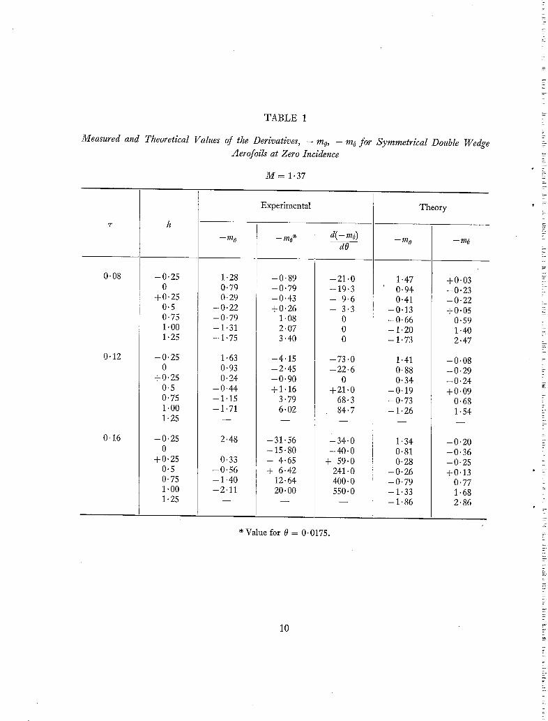
T A B L E 1
Measured and Theoretical Values of the Derivatives, - mo, - m 0 for Symmetrical Double Wedge
Aerofoils at Zero Incidence
M = 1-37
0"08
0"12
0'16
- 0 . 2 5 0
+0.25 0.5 0.75 1 . 0 0
1 . 2 5
- 0 . 2 5 0
+0 .25 0.5 0.75 1.00 1-25
- 0 . 2 5 0
+0 .25 0-5 0-75 1-00 1.25
- - m 0
1"28 0"79 0" 29
- 0 " 2 2 - 0 " 7 9 - 1 - 3 1 - 1-75
1-63 0"93 0"24
- 0 " 4 4 -1"15 - 1 . 7 1
2"48
0"33 - 0 ' 5 6 - 1 '40 - 2 . 1 1
Experimental
- 0 . 8 9 - 0 . 7 9 - 0 . 4 3 +0 .26
1.08 2.07 3.40
- 4 . 1 5 - 2 . 4 5 - 0 . 9 0 +1 .16
3.79 6.02
- 3 1 . 5 6 - 15.80 - 4.65 + 6.42
12.64 20.00
d( - m6)
dO
- 2 1 . 0 - 1 9 . 3 - 9.6 - 3.3
0 0 0
- 7 3 . 0 - 2 2 . 6
0 +21 .0
68.3 84.7
-34.0 - 4 0 . 0
+ 59.0 241.0 400.0 550.0
~-- i1/8
1 "47 0"94 0"41
- 0 " 1 3 - 0 " 6 6 - 1.20 - 1 ' 7 3
1 '41 0'88 0"34
- 0 ' 1 9 -0"73 - 1 " 2 6
1"34 0"81 0-28
- 0 " 2 6 - 0 " 7 9 - 1 " 3 3 - 1 " 8 6
Theory
-mo
+0.03 - 0 - 2 3 - 0 - 2 2 +0 .05
0.59 1-40 2.47
- 0 . 0 8 - 0 . 2 9 - 0 . 2 4 +0 .09
0.68 1.54
- 0 . 2 0 - 0 . 3 6 - 0 - 2 5 +0.13
0.77 1.68 2.86
Value for 0 = 0.0175.
10

Measured and
T A B L E 2
Theoretical Values of the Derivatives, - m o, - m o for Symmetrical Double Wedge
Aerofoils at Zero Incidence
M = 1.59
'7"
0"08
0.12
0"16
h
- 0 . 2 5 0
+0.25 0.5 0.75 1.00
- - m 0
1"01 0.61 0-23
- 0 " 1 5 - 0 ' 5 3 - 0 " 9 3
Experimental
- - m o ~
0.19 0"10 0.01 0-15 0"48 0-99
d(-m~) dO
- 6.80 - 4.4 - 6.4 - 2 - 3
0 0
- - / / ' t O
1"14 0"73 0-33
- 0 - 0 8 - 0 " 4 9 - 0 " 8 9
Theory
- - m 6
0"43 0.11
- 0 " 0 2 + 0 ' 0 7
0"35 0"84
1"25
- 0 - 2 5 0
+0 .25 0.5 0.75 1 . 0 0
1.25
- 0 . 2 5 0
+0.25 0.5 0.75 1 . 0 0
1 . 2 5
- 1 " 4 1
1.08 0"57 0-18
- 0 - 2 4 - 0 - 6 6 - 1.04 -1"43
1.14 0'63 0"19
- 0 . 2 6 - 0 - 7 0 - 1 . 1 3 - 1 - 5 4
1-90
0"27 - 0 . 0 6 +0.05
0.25 0"77 1"45 2-05
- 0 - 7 6 - 0 . 3 0 - 0 . 1 3 +0 .27
O. 89 1 . 5 9
2.47
+ 6 " 0
- 1 9 " 0 - 1 1 " 9 - 6 ' 3
0 + 2"4
10-0 28"0
- 4"0 - 6 " 6 - 4 '7 + 7"4
6"3 31 "3 16"4
- 1 . 3 0 1-54
1.10 0.36 0.69 O. 07 0.29 - 0 . 0 3
- 0 . 1 2 +O.08 - 0 - 5 3 0.39 - 0 . 9 3 0.91 - 1 . 3 4 1.62
1.06 O. 30 O. 65 O. 03 0.25 - 0 . 0 4
- 0 . 1 6 +0 .09 - 0 . 5 7 0.43 - 0 . 9 7 0.97 - 1 . 3 8 1.71
* Value for 0 = 0. 0175.
11
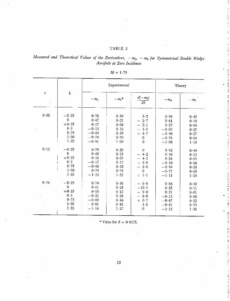
T A B L E 3
Measured and Theoretical Values of the Derivatives, - mo, ~ m o f o r Symmetrical Double Wedge
Aerofoils at Zero Incidence
M = 1.79
0.08
0-12
0"16
- 0 . 2 5 0
+0.25
- m 0
Experimental
d( - - m6 )
dO
0"78 0"47 0"17
- m o o
0"59 0"21 0"08
5-2 2.7 2.1
- m 0
0.95 0.61 0.27
Theory
-mo
0.49 0.18 0.04
0.5 0.75 1.00 1.25
- 0 . 2 5 0
+0.25 0.5 0.75 1.00 1.25
- 0 . 2 5 0
+0.25 0.5 0.75 1 . 0 0
1 . 2 5
-0"15 - 0 . 4 4 - 0 . 7 4 - 0 ' 9 1
0"79 0"48 0"16
-0"17 -0"48 -0"79 -1"10
0.74 0.41 0"10
- 0 - 2 3 - 0 - 4 9 - 0 - 8 5 - 1 - 1 4
0"16 0-39 0"70 1 "09
0.29 0-15 0.07 0.17 0.38 0.74 1.23
0.36 0.24 0.13 0.28 0.46 0.81 1.27
- - 3"5 + 4"7
0 0
0 - - 4.2 - - 4 " 3
I
- - 5.0 + 2 . 0
0 + 1.1
- 6 . o
- 1 0 . 3 - - 9 . 8 - 8.0 + 0.7
3 . 5 0
- 0 " 0 7 - 0 " 4 0 - 0 . 7 4 - 1 "08
0"92 0"58 0"24
- 0 " 1 0 - 0 . 4 4 - 0 . 7 7 -1"11
0"88 0"55 0"21
-0"13 - 0 " 4 7 - 0 . 8 1 - 1 . 1 5
0" 07 0" 27 0"64 1.18
0.44 0.15 0"03 0"08 0"30 0"68 1.24
0-38 0-11 0-01 0-08 0-32 0"73 1-30
e Value for 0 = O. 0175.
~12

T A B L E 4
Measured and Theoretical Values of the Derivatives, mo, m6 for Symmetrical Double Wedge Aerofoils at Zero Incidence
M = 2.15
'T
0"08
0"12
-, 0.16
- 0 . 2 5 0
+0.25 0.5 0-75 1.00 1.25
- 0 . 2 5 0
+0.25 0.5 0.75 1.0 1:25
- 0 . 2 5 0
+0.25 0 - 5 0 .75 1.0 1.25
- - m 0
0,60 0.36 0.11
- 0 . 1 2 - 0 . 3 5 - 0 . 5 8 - 0 . 8 0
0"52 0.31 0-07
- 0 - 1 6 - 0 - 3 8 - 0 - 6 0 - 0 . 8 2
0.44 0.22 0.01
- 0 . 2 1 - 0 . 4 2 - 0 . 6 1 - 0 . 8 1
Experimental
_ m6~-
0'44 0"21 0-11 0"13 0-25 0"50 0"80
0"52 0.28 0"19 0"19 0.33 0"51 0"80
0.45 0.40 0.33 0.30 0.33 0.39 0-66
d(-mo) dO
0 0
- 4.4 0 0 0
- 5 . 3
- 8 . 4 - 3 . 3 - 3.0 - 2 . 5 + 0 . 9
1 .6 8.2
- 2 8 . 9 - 2 0 . 2 -11 .6 - - 8.2
0 + 4 . 5
14.1
- m 6
0.73 0.47 0.21
- 0 - 0 6 - 0 . 3 2 - 0 . 5 8 - 0 . 8 5
0.71 0.44 0.18
- 0 . 0 8 - 0 . 3 5 - 0 . 6 1 - 0 . 8 8
0.68 0.42 0.15
- 0 . 1 1 - 0 - 3 8 - 0 . 6 4 - 0 - 9 0
Theory
I.
-m6
0"46 0"20 0"07 0"07 0"20 0"46 0-86
0.42 0-17 0.05 0.07 0 . 2 2 0.50 0"91
0.37 0.14 0.04 0.07 0-23 0-53 0-95
Value for 0 = 0. 0175.
13

Measured and
T A B L E 5
Theoretical Vahles of the Derivatives, - mo, - m 6 for Symmetrical Double Wedge
Aerofoils at Zero Incidence
M = 2.43
0"08
0.12
0.16
h
- m 0
- 0 . 2 5 : 0.51 0 0-32
+0.25 0.10 0.5 --0-10 0.75 --0"30 1.00 --0.49 1.25 - 0 . 6 8
--0.25 0.44 0 0.24
+0.25 0.04 0-5 - 0 . 1 4 0.75 - 0 . 3 3 1.00 - 0 . 5 2 1.25 - 0 . 7 0
- 0 . 2 5 0.33 0 0.16
+0.25 - 0 . 0 2 0.5 - 0 - 1 8 0.75 - 0 - 3 6 1.00 - 0 - 5 4 1.25 - 0 . 7 2
Experimental
0'41 0"16 0"06 0"10 0"20 0'46 0"70
0"44 0"16 0-16 0"14 0-25 0"46 0"62
0"59 0"33 0"31 0"22 0"26 0'35 0"23
d(-mo) dO
5.0 1.6 0.6 0.3 1.8 7.5
13.0
10"3 0
- 1-3 0
+ 0"4 6"4
- 0"3
0 0
- 6.9 - 2 . 3 + 0.4
5-8 0.2
- m 0
0"62 0"40 0'17
- 0 ' 0 5 - 0 ' 2 8 - 0 " 5 0 -0"73
0.60 0.37 0-15
- 0 . 0 8 - 0 - 3 1 - 0 . 5 3 - 0 . 7 6
0.57 0.35 0.12
- 0 . 1 1 - 0 . 3 3 - 0 . 5 6 - 0 . 7 8
Theory
-m~
0-42 0.19 0.07
• 0.06 0.17 0.39 0.72
0.38 0.16 0.06 0.06 0.18 0.42 0.77
0.34 0.13 0.04 0-06 0.20 0.45 0.81
~ Value for 0 = 0.0175.
14

T A B L E 6
Measured Values of the Derivatives - too, - m 6 for a 12 per cent
Symmetrical Double Wedge Aerofoil at Various Angles of Incidence
M = 1.37
0.25
0"5
e~ (deg)
0 1 2
2.5 3
3.5 4 5
- - m 0
0.25 0-24 0"18 0"35 0-28 0-26 0"25 0-24
- - m6~
- 0 . 8 4 - 0 . 8 0 - 1 . 9 3 - 4 . 8 6 - 4 . 2 6 - 2 . 2 8 - 0 . 7 4 + 0 . 3 2
d(--mo) dO
- 0"3 + 13"0 - 1 0 7 " 1
+ 1 5 9 ' 1 114'3
- 56"3 - 23"7 + 4"3
0 - 0 - 3 7 1 - 0 . 4 2 2 - 0 . 5 1 3 - 0 . 4 5 4 - 0 . 3 5 5 - 0 . 2 7
0.65 6.6 1.29 22.0 2.63 4 .0 5.32 - 49.7 4.53 + 37.1 2.68 39.4
T A B L E 7
M = 2.43
h ~(deg)
0 2 4 6 8
10
- m a
0" 24 0"35 0"38 0-36 0"39 0"40
0-16 0"14 0"14
0"13 0"13
d ( - m6)
dO
0 + 11.7
0
0 - 19.0
* Value for 0 = O. 0175.
15

T A B L E 8
Measured and Theoretical Values. of the Derivatives - mo, - mo for a 16 per cent Single Wedge
Aerofoil at Zero Incidence
M
1"37
1 " 5 9
1"79
2.15
2.43
- 0 . 2 5 0
+0.25 0.5 0.75 1.00 1.25
- 0 . 2 5 0
+0.25 0.5 0.75 1.00 1.25
- 0 . 2 5 0
+0.25 0.5 0.75 1-00 1-25
- 0 . 2 5 0
+0 .25 0.5 0.75 1 . 0 0
1 . 2 5
- 0 . 2 5 0
+0.25 0.5 0.75 1.00 1.25
- - m 0
2"15 1"37 0"56
-0"15 - 1 . 2 5
1 "58 1"02 0-54
- 0 - 1 0 - 0 - 5 9 - 0 - 9 2 - 1"54
1"21 0"81 0"40 0
-0"41 -0"81 - 1 " 2 0
0"97 0"64 0"38 0
- 0 - 3 2 - 0 - 6 3 -0"95
0"83 0"55 0" 27 0
- 0 ' 2 8 -0"55 -0"83
Experimental
- - m 6 *
- 5 . 4 0 '
- 2 . 3 0 - 0 . 5 2 +5-07
- 0 " 0 7 - 0 " 3 4 -0"58 - 0 . 0 7 +0"76
1 "62 2"15
0.77 0"31 0"03 0-03 0-32 0"76 1.28
0"57 0"20 0" 07 0"06 0"23 0"54 0"96
0"54 0.19 0"08 0"06 0"20 0"47 0" 84
a(-m6) dO
- 1 4 1 . 6
- 32-4 + 36-4
0
0 - 2.2 - 7.0
0 - 3 . 4 4
+ 7-36 16.0
0 2.23
- 1.31 0
+ 5-0 2.7 0
1.3 1.0 0
- 0.2 + 0-2
0"6 2.2
1.7 0 0.9 1.0 2.5 7.8
19.8
- - m 0
1.99 1.33 0.66 0
- 0 - 6 6 - 1 . 3 3 - 1.99
1.46 0.97 0.49 0
- 0 . 4 9 - 0 . 9 7 - 1 . 4 6
1.21 0.81 0.41 0
- 0 - 4 1 - 0 . 8 1 - 1 . 2 1
0.96 0-64 0.32 0
- 0 . 3 2 - 0 . 6 4 - 0 . 9 6
0.84 0.56 0.28 0
- 0 . 2 8 - 0 . 5 6 - 0 . 8 4
Theory
- m 6
- 0 . 2 5 - 0 . 5 4 - 0 . 5 0 - 0 . 1 4 +0 .56
1.60 2.95
0"53 0.12
-0"05 +0"03
0"35 0-91 1-72
0"65 0"25 0"06 0"06 0" 27 0"68 1"29
0"65 0"30 0"11 0"07 0.20 0"49 0"94
0"61 0-29 0"11 0-07 0"17 0"41 0"79
* Value for 0 = 0.0175.
16
G
LinBr
Workin 9 sechiDn
ModeJ
5biffenin S girder
FIG. 1. Cross-section of wind tunnel showing general arrangement of model mounting.
V-- I ¢_&
L P
-71 I
FIG. 2. 1
Model mounting viewed from side of tunnel.
17
(s2872) B

Fit3. 3. Photograph of one model mounting with cladding removed.
Condenser 9au9 e
I F.M [ o~cilla~,or
IO00 c.p~. ~l:andard
N. P. L. frequenc~l frequency divider
$ou~,hern Insl:[ F. M. amplifier I
di~criminakor I
Pulse~ ak~ I, 0% o.oJ se~. inb~rvals
Fxc. 4. Schematic diagram of recording apparatus. 18
2"0
1"5 \ \ \
I ' 0 ~ .
0"5
0
-0'5
-I'0
-1"5
-2" -0"25
FIG. 5.
Theory (•ef. 5) . . . . . . Experimenb Theors ~0°1o . . . . . Chord cur. off from ~rai~i~ ed�~ )
\ \ N\, %, \%;\
0 0"2`5 0"50 0"7`5 , 1-00 1-25 ?z
,5 Theory (Ref. 5) " ExperimenC o ~
4 Theor~ (40% - - . - chord cur. of f from , .
2, brailinc ~ ) l / -
I / /
I S f"
'-I
,-2
-3 1"50 -0'25 0 0"25 0"50 0"75 I'00 1,25 l'50 h
Dependence of - m o and -mo on h for a double wedge aerofoil ~- = 0.08, M = 1.37, c~ = 0.
2"0 L [ 5
'`5 4
Theory (Re.~:. 5)
1"0 \ \ \ N I gxpenmenb o 3 ,
\ ~ / / / 0"5 2 / /
-%0 -~et ___c-/ / / [
-0'5 0 ~
-1"5 -2 \ \
\ -2-0 \ \ - 5
-2.5 -0"25 0 0-25 0-50 7l, 0"15 1-00 1"2-5 1'50 "25 0 0'25 0-50 h- 0-75 1-00 1-25 .1'50
FIC. 6. Dependence of - m o , - m 0 on h for a double wedge aerofoil ~- = 0.12, M = 1.37, e~ = 0.
19
(82872) C

~0 --rr't 0
1'5
I '0
0"5
0
- 0 .
-l'q
-lq
-Z~O
- O'Z5
5
4
x \ L - Thcor~ (R¢~.5)
I
\ ' - , , o
\\ " -I \ \
\ N \ --3
" 0 O.ZS 0'50 0-75" I'00 1.25 1.50
FIG. 7.
- - ~ gxperimcnl/ -
/ - 0"Z5 0 O-Z5 0"50~ 0"75 1-00 l-Z5 I'50
D e p e n d e n c e of - m 0 , - m 0 on h, for a double wedge aerofoil, ~, = 0 .16 , M = 1.37, ~ = 0.
Z'0 -%
1"5
I'0(
0'5
0
-0 '5
- I ' 0
-I'5
- Z'0(> g 5
! I I I
. . . . . Tho-,or~ ( R~-{. ,5) o ExpCrimeng
. x
%' \ L \ .,.
5
4
FIG. 8.
I I i ,
. . . . . . Theoc,~ I ( ReA:. 5) .. o - - - Exp~rimenb
t
0 -0'25" 0"50~. 0"75 1.00 i'25 1.50 - kZ5 0 0"Z5 0'50}z 0'75 I'00 I'Z5 1"50
D e p e n d e n c e of - m o , - - m 0 on h, for a doub le wedge 'aerofoi l , ? = 0-08, M 1.59, a = 0.
20
7 =2
-2
7

2-O
-11/, 0
1'5
-2. - ) -2 .5 0
Fie . 9.
I J I
. . . . Thcor~J (, Re.£ 5)
.o---- Exp~rim6nb
0 '25 0 ' 5 0 0" /5 I ' 00 1-25 I'SO 7~
5 -rr~
4
i I I .... Theor U (.Re.£ 5)
----o----- gxpe.rime~nb
- Z
(
- I
-O .ZS 0 0-2-5 0-50 0"7~ 1-00 I 'Z5 1-50 7~
Dependence of - m o , - t o o on h, for a double wedge aerofoil, 7 = 0 .12, M = 1.59, a = 0.
Z'0
1"5 - rrc 0
I'0~
0"5
0
- 0 " 5
- I ' 0
- I "5
- ZL00 . Z 5
F I G . 1 0 .
a - - - - E x pe.cirnenb
' \ k .
0 O'Z5 0'507~ " 0 '75 I'00 1"25 1"50
I I I I . . . . . Thcor~ ( Re.~:. 5"}
_.rn. 6 -----o---- E .×p~ . r imenb
Z
I
~'~ ,~,~ ~ , t j j
J - I
- Z
- 5 - 0-Z5 0 0'2.5 0 '50 /!. 0 '75 1.00 I'Z5 1.50
Dependence of - m o , - m O on h, for a double wedge aerofoit, 7 = 0.16, M = 1.59, ~ = 0.
21
(82872) C 2

1'5 -~ ~hoo~ ~o~.5) . . . .
0-5
0
- I . 0
- I . 5
- 2 . 0 - 0.25 0
t
.3
-/~
2
1
~1
- 2
-3 0'25 0"50 0"75 I-OO 1'25 1'50 -0"25 0'25 0'50 0"75 I'00 1'2F 1'50 7z
Fro. 11. D e p e n d e n c e of - t o o , - m 0 on h, for a doub le wedge aerofoil, ~- = 0 .08 , M = 1 .79, o~ = 0.
2"£
1'5 ! Th~or~ ~ef:. 5)
gx perimenb o I,O
° 'S l 7 " ~ \
o
-0"5 i
x,
- I . 5
- 2'-00"25 0
FIG. 12.
4 I TheorEI ~e~ Experimenb - = - - - 0
3
- r r ~
2
0
- I
- 2
- 3 o.25 o5o h, o.75 ~-oo 1-25 J.5o -0-25 o o.25 0.50 h, 0.75 f.oo 1.25 1.6o
D e p e n d e n c e of - t o o , - m 6 on h, for a double wedge aerofoil, ~- = 0 .12 , M = 1 .79, ~ = 0.
22
1.5
1-0
0-6
- 0 - 5
- I - 0
-1-5
-2.,n
-?.-5 -0-2~
, ~xperirnmnk ~ ,
F m . 13.
4-
"?"~ d
Z
I
0
-2
- 3
~4 -0-2S
I I I "rh~or-u (~:.~ ExpeHmer~k
0-25 O. SO 0-7~ ;h. I , o o I.'zG . , s o o-26 o - so 0.75 7z boo 1-25 hSo
Dependence of - m o , - m 6 on h, for a double wedge aerofoil, ? = 0.16, M = 1.79, ~ = 0.
l . s I I I Theorg (~ef. s)
I-O Exper ' imenk o
- z'z,O
0.5 o -0 -5
- I ' 0 ~
- 2 ,0
- 2 - 5 0"2~ o
FIG. 14 .
O'ZS 0-50 0,75 bOO 1-2{; l-SO 0.75
4"
3 - ~
2
- I
- 2
I-OQ b25 1'50
- 3
4 - 0-25 0 0.25 . 0 .50
I I t "rh~o~-~ ( ~ S) E xpe r - lmenk o
Dependence of - m o , - m 0 on h, for a double wedge aerofoil, r = 0 . 0 8 , M = 2 ' 1 5 , e~ = 0 .
23

2.0
I-5
0
- 0-5
. - 1 -0
1-5
2 "0~o.'~ 5
I I I rheor" u (P, ef. 5 ) ~xpeHrnenk o
--.. .
0 ' 2 5 0 -50 0 " / 5 7Z 1-00 1-25 I-SO
4"
5
- I
- 2
- 3 - O- 25 o 0-2S 0-05
I T h e o r - ~ E ~ (pe r - imen~
0.75 7z bOO 1-25 t-50
Fro. 15. D e p e n d e n c e of - m o , - m 6 o n h, for a doub le wedge aerofoil, ~- = 0 .12 , M = 2-15, c~ = 0.
2 .0
..-m. 0
I -5
I 'O
0 . 5 1 " ' . . . ¸
- 0 " 5
~1-O
-1=5
-2"0 - - ~ , 5 5 0
FIc . 16.
5
T h e o r y Expe rrn~e~}: 0
0.7s I-oo h i .zs I- so
I
0
I I I r h ~ o , - ~ ( R d . ~) - - - - - - E x p e r [ r n & n ~
- I
~ 2
3 o - 2 5 o - 5 0 - 0-7.5 o 0 - 2 5 0 - g 0 0 - 7 5 I ,oo ;h I.Z5 1.50
D e p e n d e n c e of - m o , - m 0 on h, for a doub le wedge aerofoil, ~- = 0 .16 , M = 2 .15 , c~ = 0.
24

2.0 -Tn 0
"1-5
['0 .
0 - 5 ~ . ~
-0-5 I -i-O -I'5
-2"0 - O,9-S 0 0-~6
F I G . 17.
, i Exper-{menk. o Pisken kheory ×
0,50 0-75 7% I-0O I.Z5 b5o
5
- 2
--3 ~0-25 0 O-Z5 O.SO 0.75 ~ 1-00
The.o~ 9 (Be{. 5) ' E xpe r.-~ m enlr., o Pica.on lheor 9
(~;. 7)
1'25 1,50
D e p e n d e n c e o f - t o o , - m 0 on h, for a double w e d g e aerofoil , 7 = 0 . 0 8 , M = 2 . 4 3 , a = 0.
gxperimenE o I -5 Pi~,Eon ~heorg X
- 0 - 5
-I-O
-I-5
-2 -O O-2S 0 0"25 0-50 0"75 7~ UO0 ]'2S
0
- 2
-3 1"50 0-2s 0 Cy25 0"50
, i i
Theor -c 3 (ae4:. s) ~_ x p e r i r n e r ~ o e iskon {:hec~r 9 X ' (~.~: 7)
0-75 "h bOo I.?.5 1"50
FIG. 18. D e p e n d e n c e o f - m o , - m 6 on h, for a double w e d g e aerofoil , ~- = 0 . 1 2 , M = 2 . 4 3 , ~ = 0.
25

2-0
1"5
1.0
0'5
-?Tb 8
0
- 0.5
-I'0
- b 5
- 2"0 -0 ' 25 0
FIa. 19.
I I
Theors @e£ 5)------
gxpeHmenb - - -O-- -
Pisbon bheor~l
(r~f. ~) x
" x . .
5
theory (Ref. 5 ) - - - 4 ExpeHmenb
Pisl;on bheonj
2
I i
-I
- 2
-3 0'25 0"50 Tz O.q5 I'00 1"25 1'50 -0.25 0"25 0.50 "h. 0"75 I'OD ]'25 ]'50
Dependence of - t o o , - m 0 o n h, for a double wedge aerofoil, -r = 0 .16, M = 2-43, c~ = 0.
26
"-,.I"
-i~t e
I - I
1.0
0 . 9
0.'~
\
0-7
O'6
0-,5--
0"4
0 " 3 - -
0"2
O ' t
Ol. O
\
\
\ \ \ \ \ \ \
/ Colla.r "~'
\ \
\ \
N X
\
/ -,
I 141 . !i
IIF L,Z
- - F-xper'imenk __ "fheor 9
\ \
\ \
2 " . . . . . . . .
"" -,,, "- ,,,. Va.n Dgke $
%.-L" -,. -L
1.4 I-6 I-g ~t~ z'~ 2-2 -2-4
Fie. 20. Dependence of - m o for double wedge aerofoils on M and r, h = 0.25.
-zt 6 0..=
0"2
~ 0 " 1 - -
I'O 1"4
- 0 . 1 - - "~'= 0 . 0 4 - ~ ' - - "
T= O - O g / -L-=O.I~L "l; = 0 + 1 6 " - - ' - - " ~ "
0 . 2
I
,O.=t - - l I
- 0 o - - - -
t - o q - - [
I I I
PO -1 [
- O ' l - -
- O , - - ,1
- I
FIc. 21.
H i - m a = - 4 . 6 6
I , . , # ' . . I A I
' T - - "Z- a,
Dgke s
~Exper;men~ - - - - - -Theor~
Dependence of - m O for double wedge aerofoils on M and % h = 0.25.
, t , a (3¢
o ! Coll,~r~ T e m p l e ai'~ll:t J ' a . h n i l - ' m - e : O " : " t o ~ = . o.O~t]_._ ~ .
. . - ; r e . , _ _ - 7
17" - - I ~ ~
!/i i / 0 " 5 I
0.~
0-'7
0-~
0,5.
0 -~
. . . . T h e o r g o. 5
r
II -o.~ - /I ° "~
II -o-'~ LL, o-I
I I I
- O -~ -- 0
-Ill - 0 ~
II
- i . , l l [ l I I 1 o-s , . o , ~ , 4 , ~ , ~ ~ o ~ . ~
FIG. 22. Dependence of - m 0 for double wedge aerofoils on M and ~, h = 0- 50.
I
' I.IfJ "1 I I I I I~
I_1 "1 I I 3 I j,4 "c°"~
i III -i ~ i I I I
I It "'l' ~ --, l l - - -- i-~ a.nd Ch]nnecl¢
_1 iI
. ! - - \ - 1 - 1 4 - - \ i l l ',,t tt
- ~ / - - - - - - -
- ' , , , < ', t ',,o +~
\-,0"0 0 _ --
I " ~ . I " -
- - I I - - - - . o ~ - 4
- - I / / ',.J /
/ /
~ .Ten~ple omd 3"echn 2_
/
I-O I.z I-~- I-g I-~.
E x p e r i m e n E . . . . "/'heom.j
o ] "E: @lt~
2" = 0 ' 1 2 - -
. . . . . _-_r- . . . . . !_
I z.o 2-2 2-~f
M
Fm. 23. Dependence of - m 0 for d9ubte wedge aerofoils on M and % h = 0.50.
s
~,Hu': "i ', ' ; ' , ~; ; , !",,~'i','~ ri'l~"~r":'~"p " ' l l ' r , i~ ' i ' i [ i ; ' i l : r "Nr ' l " l ! rH' i ' i~ ' i " i i " i i r i : i~; ; ' , ~:717~"!' i, i '~;i i~' "It'I r : ' I ' ur'!l l"lr' i"=lF! r '~ir' "1i" '~ir ~= :I ~r~i: 'PHl' i ' ! ;rl"ii! ' ' i i;r I'i!i:ilUli' i!~'1 i l i ' i l " l ~1i ' 'p'i~ i"!il ;~' ~ l~lH!ll~!!~r!' III! 'GrlI!I ' I i i : ' i l ! i i l ' i i i ' ! ' ] ! ! l"~l~"l r l ' ! i i i ' l l 'hi l ' i ! ! ' l i lG:1 ~'!'i 1," l r i l r ' I F!I ~ ' r i l i~ilF ! "
d
-0";
-711. D
--0"3
- - 0 "
-0°.~
° 0 - '
- 0 ' 9
- 1 " 0
~ = 0 . 0 8
- I -;
- I - -
- I , ,
Van
/t
/11/ i tit II
//
tt?~
II Ii I I
I I I
1.2
FIa. 24.
/ / /
f i..3
~ = 0 , 1 2
"C=O4~,
- - E x p e r i r ~ e ~ 6 . . . . . Y h { o w 9
I I I I I-,4 1,6 I ' ~ ~ '0 ~"2 Z'~" I'1
Dependence of - m o for double wedge aerofoils on M and ~, h = 0" 7 5 .
1.2
- r a d
I - I
1 " O - -
0 - 9
0 , 9
0 " 7
0 , 6
0 ' 5
0"4
0 , 3
0,2
0'I
01, o I.Iz
Fia. 25.
L~ i Ir
I l ~ - - E x p e r l r n e . E ~I -- - - --Theor 9
iii!-I - - I I I ~ / L "c ol~
l l l ~ 1 • _
- ',', ' 2 4 I \,0 ~,6 N\o~
- \ \\\\\
I . I I 1,+ I-6 1-0 z-o ~.2 M z-4
Dependence of - m o for double wedge aerofoils on M and % h = 0 " 7 5 .

2.0
1"5
1.0
0'5 -7/b
O
0
- 0 ' 5
- I '£
-1"5
-2-0
-2 .5
2.0
1.5
I-0
0'5
-%
O
Theor~
ExperimenD
I
k=O~O .......
).04
h=l.0
0.08 "c 0.12 0.16
5
4
3
- ~
0
- I heory -2 ~ 0
- 3
--15'8
- 4"0-04 0-08 -~ 0.i2 0'.I6 FIG. 26. Influence of thickness/chord ratio on the derivatives for double wedge aerofoils,
M = 1-37, ~ = 0.
-0"5
-I 'C
-I-5
-2"0 0'04
I 1 Theory
Experirnenb
I ~ = 0 " ~ -o.....
h=l.O~_ I
I Theory Experimenb
5
4
3
2
--77b. 0
I
0
"I
--2
--3 0-04 @ 0 8 "t" 0"12 0" t6 O'OB ~c . 0'12 0-16
FIG. 27. Influence of thickness/chord ratio on the derivatives for double wedge aerofoils, M = 1 " 5 9 , ~ = O.
30
1.5
1.0
0.5
-% o
-0'5
-I '0
~1-5
-2-0 0"04
FIG. 28 .
Theory
Experimenb O
/7=0'50, o
" h . = l - O ~
5
4
3
2 - W ' b .
e
[
0
- I
- 2
- 3
Theor9
E×perimenb O
h = 0 . 5 .,.o o
0'08 T 0.12 0.16 0'04 0"08 "r 0-12
Influence of thickness/chord ratio on the derivatives for double wedge M - - 1"79, c ~ = 0 .
0"16
aerofoils,
1-5
I 1.0 Experimenb 0
0"5 Theor~ @ef.5~
-0.5
- I .0
-I .5
-2.0
0 I
FIG. 29 .
2 3 4 5 -degrees
I
--'fib. o
0
_1 I
-2
-3
- 4
Experimenb Theor~ ~ef. 5)-
3 4 5 ~ ° - d e q r e e s
Effect of mean incidence on the derivatives for double wedge aerofoils, M = 1.37, h = 0.25, -r = 0.12.
31

2.0
1'5
-7/~ 0
I '0
0"~
0
E xperimenb o
T h e o r y ~l~e£ 5 D
-I.0
-I'5 0 I
FIG. 30.
5
4
-~6 3
2
I
2 3 4 5 6 c~ -de~rees
-I
-2
J
\
E xper imenC
Theor,q ('Ref. 5)
1 I 2 3 4 5
c~°- degrees
Effect of mean incidence on the derivatives for double wedge aerofoils, M = 1.37, h = 0.5, z = 0.12.
~ '0
I'~
I ' C
0.5
0
- 0 " ~
- I 'C
- 1 ' 5
0 2.
I - - - o - - - - E xp~r i rn~nb
. . . . T h ~ o r ~ (R~,£ 5)
__ . _ _ _ _
FIG. 31.
4
----'O----- E X pmrimcn b
. . . . Th e.or,~ ( Re,{. 5)
t
0 . . . . . . . . ~ ~, "~-"
4 6 B tO 0 Z ~t 6 8 I0 Ex - des re ,6~ ~x - d e , ~ r ~ , 5
Effect of mean incidence on the derivatives for double wedge aerofoils, M = 2 . 4 3 , h = 0 , ~ - = 0.12.
32
2.'O
- rrt'lg' X 1 ' 5 - - --
I'0
0"5
0
-I.0
-I-5
- 0'2.5 0
| I
. . . . . . Theory (R¢£. 5) ' ~ j E x~e~rlmgtqb
x\
o
0"g5 0'50 "h. 0"75 I'00 I'Z5
FIG. 32.
J 5
/ 4
z j j-- I 1 >////I o I" I
/ .... Theory [ RC~.6) " ~ E x pcrirncnb
Z
1'50 0.25 0 . 0.z5 0'50 ~ 0'75 1-00 1.2..5 1.50
D e p e n d e n c e of - m o and - m 6 o n h for a s ingle wedge aerofoil, ? = 0 .16 , M = 1 .37 , o~ = 0.
Z'C-
o o
I -5\ \
\ i.o ~,
\ \
o.~
-o .
-I-(
-I .5
-2.0 - 0"Z5 0
FIG. 33.
I ~ r ' f 5
o Experimcnb -- Zl
\ \
o \ \
\
',,0 \
\ \
' \
. . . . ~ - ~ o ~ ( ~ s) , - - EX )e.rinqe_nl~ - "
-Z
0'2! 0"50 ~ 0"75 I-O0 I'Z5 1"50 -O'Z5 0 0"2-5 0"50 }a 075 |'00 )25 1"50
D e p e n d e n c e of - m o and - m 6 o n h for a s ingle wedge aerofoil, -r = 0" 16, M = 1" 59, e~ = 0.
33
Z.O
- ,.m. 0
1'5
1.0
~,,,,
0'5
0
- 0 ' 5
-I.ID
-1"5
-Z:O -O-Z5 0
FIG. 34.
~0
l '5
I '0o
0'5
- 0 .
- I ' l
- I . 5 I
-0 'Z5 0
FIO. 35.
\ \ 0 \
. . . . The.or~ (Re,{.5) o E xpcrime.nb
X Pisbon bhe~or~ (Rc.f. 7)
"-.o I. \
\
\ % \
\x. K
O N
"o, \
\
5 - w %
4 1
Th~or.~ (a¢.~. 5) 5 o E x pe..d~mc.nb - -
/
X i~i~bon bhe.or~ (Re..'~.7)
i f o /
I f
. O ~ X
' ~ - o - - - - ~ - ~ " 0
-I
O'Z5 O-50}z 0'3'5 1.0{3 I'Z5 1.50 --O'Z~ O 0'Z5 0"50 k 0"75 I.oo I-Z5 1'50
D e p e n d e n c e o f - m o a n d - m d on h f o r a s ing le w e d g e ae ro fo i l , ~- = 0 . 1 6 , M = 1 . 7 9 , cx = 0.
. . . . Theor~ (Ref. 5") o EX ~ e~rim~nb X Pie, boa bhg-or~l (Rel:.7)
"- . I ! x. .o
"%, .
"o..
" "" %" XX.
I
0'25 0'5"019. 0'75 I'00 l'Z£t
3
I
o
. . . . Th~.or~ (Re,f.5) o F- xp~riraenb
x Pisbon bheor~l {.Ref.7)
! L . . . . . . I
" - - o . . . . o - - - -
:50 0 0"2.5 0"60 Jz 0.75 1.00 1"25 1.50
-I
-Z
--50.2ff
Dependence of - m o and - m 0 on h for a single wedge aerofoil, r = 0-16, M = 2.15, ~ = 0.
=--
E- 52_
• 7 Z _
34
~0
-~7, e
I'S
I '0 ). .
0"~ ~ ' - ~
0
-0 '5
-I-0
-1'5
-2-0 -O'z5 0
FIG. 36.
I . . . . Theoc~ (Re.,I'.5')
E x pe.ri mo~n~ Pisbon bhe.~c~ (REX.7)
%.
" " ' o ,
"o...
-% I Theor~ (Re_~:. 5)
5 o Experiment, X Pi.~bon bhe.or~ (Re.f?/)
! I 9 1 /
0
I - I
-2
- 5 ' 0-2.5 0.50. h 0:75 1.00 I.Z5 1.50 -O.ZS" 0 0-2.5 0-50 h 0.75 I.O0 1.25 1-50
i
Dependence of - m o a n d - m 0 on h for a s ing le wedge aerofoil, ? = 0" 16, M = 2 ' 4 3 , a = 0.
(82872) Wt. 67/1876 K.5 1/62 Hw.
35

• - . . . , , ,
Publications of the Aeronautical Research Council
A N N U A L T E C H N I C A L R E P O R T S O F T H E A E R O N A U T I C A L R E S E A R C H C O U N C I L ( B O U N D V, O L U M E S )
t94I Aero and Hydrodynamics, Aerofoils, Airscrews, Engines, Flutter, Stability and Control, Structures. 63s. (post ~s. 3d.)
t942 Vol. I. Aero and Hydrodynamics, Aerofoils, Airscrews, Engines. 75s. (post 2s. 3d.) Vol. II. Noise, Parachutes, Stability and Control, Structures, Vibration, Wind Tunnels. 47s. 6d. (post xs. 9d.)
t943 VoL I. Aerodynamics, Aerofoils, Airscrews. 8os. (post 2s.) Vol. II. Engines, Flutter, Materials, Parachutes, Performance, Stability and Control, Structures.
9os. (post 2s. 3d.) t944 VoL I. Aero and Hydrodynamics, Aerofoils, Aircraft, Airscrews, Controls. 84s. (post as. 6d.)
Vol. II. Flutter and Vibration, Materials, Miscellaneous, Navigation, Parachutes, Performance, Plates and Panels, Stability, Structures, Test Equipment, Wind':Turmels. 84s. (post as. 6d.)
• 94s Vol. I. Aero and Hydrodynamics, Aerof0ils. ,los. ~p~st is.) Vol. II. Aircraft, Airserews, Controls. t3os. (post 3s.) Vol. III . Flutter and Vibration, Instruments, Miscellaneous, parachutes, Plates and Panels, Propulsion.
x3os. (post 2s. 9d.) Vol. IV. Stability, Structures, Wind Tunnels, WindTurmel Technique. I3os. (post as. 9d.)
t946 Vol. I. Accidents, Aerodynamics, Aerofoils and Hydrofoils. x68s. (post 3s. 3d.) Vol. II. Airscrews, Cabin Cooling, Chemical Hazards, Controls, Flames, Flutter, Helicopters, Instruments and
Instrumentation, Interference, Jets, Miscellaneous, Parachutes. z68s. (post 2s. 9d.) Vol. III. Performance, Propulsion, Seaplanes, Stability, Structures, Wind Tunnels. i68s. (post 3s.)
t947 VoL I. Aerodynamics, Aerofoils, Aircraft. x68s. (post 3 s. 3d.) Vol. IL Airserews and Rotors, Controls, Flutter-, 'Materials; Miscellaneous, Parachutes, Propulsion, Seaplanes,
Stability, Structures, Take-off and Landing. x68s. (post 3s. 3d.)
Special Volumes Vol. I. Aero and Hydrodynamics, Aerofoils, Controls, Flutter, Kites, Parachutes, Performance, Propulsion,
Stability. x26s. (post as. 6d.) Vol. II. Aero and Hydrodynamics, Aerofoils, Airscrews, Controls, Flutter, Materials, Miscellaneous, Parachutes,
Propulsion, Stability, Structures. x47s. (post as. 6d.) Vol. III. Aero and Hydrodynamics, Aerofoils, Airserews, Controls, Flutter, Kites, Miscellaneous, Parachutes,
Propulsion, Seaplanes, Stability, Structures, Test Equipment. x 89s. (post 3s. 3d.)
Reviews of the Aeronautical Research Council x939-48 3s. (post 5d.) 1949-54 5s. (post 5d.)
Index to all Reports and Memoranda published in the Annual Technical Reports x9og-x947 R. & M. 2600 6s. (post ad.)
Indexes to the Reports and Memoranda of the Aeronautical Research Council . . . . . Between Nos. 23~*-'2449
Between Nos. 245x-2549 Between Nos. 255I'-2649 Between Nos. 265x--2749 Between Nos. 275x-2849 Between Nos. 285I--'z9:49 Between Nos. 295x-3o49
R. & M. No. 2450 2s. (post 2d.) R. & M. No. 2550 as. 6d. (post 2d.) R. & M. No. 2650 as. 6d. (post 2d.) R. & M. No. 2750 2s. 6d. (post 2d.) R. & M. No. 2850 as. 6d. (post 2d.) R. & M. No. 2950 3s. (post 2d.) R. & M. No. 3050 3s. 6d. (post 2d.)
HER MAJESTY'S STATIONERY OFFICE from the addresses ov~leaf
© Crown c@yrighg x96z
Primed and published by HER MAJESTy'8 STATIONERY OFFICIE
To be purchased from Yo~k House, Kingsway~ London w.c.z
4z3 Oxford Street, London w.x x3 :~, Castle Street, Edinburgh 2
x09 St. Mary Street~ Cardiff 39 K~Jng Street, Manchester ~,
5o Fairfax Street, Bristol 2 Edmund Street, Birmifigham 3
8o Chiehester Street, Belfast x or through any bookseller
Pdnted in England
& M° NOo 3234
S.O. Code No. 23-3234