MEASUREMENT - Squarespacestatic.squarespace.com/static/50b53c96e4b0cf86c3e6663e/t... · Awarded the...
35
MEASUREMENT and CONTROL For Shipbuilding & Offshore ENGLISH
Transcript of MEASUREMENT - Squarespacestatic.squarespace.com/static/50b53c96e4b0cf86c3e6663e/t... · Awarded the...

MEASUREMENT and CONTROLFor Sh ipbu i ld ing & Offshore
ENGLISH

CONTENTS04 COMPANY PROFILE
06 CEO MESSAGE
10 CARGO MONITORING & CONTROL SYSTEM12 Radar Beam Type Cargo Tank Monitoring System14 Magnetic Float Type Cargo Tank Monitoring System
16 TANK LEVEL GAUGING SYSTEM18 Electric Pressure Type Level Transmitter LEVEL-3000™20 Air Purge Type Tank Level & Draft Gauging System22 Electric Pneumatic Type Tank Level & Draft Gauging System24 High Precision Electric Pneumatic Type Level Transmitter26 1:1 Converter (Pneumatic Tank Level Gauge)
28 ALARM SYSTEM30 Magnetic Float Type High & Overfill Alarm System32 Water Ingress Alarm System34 Pressure Monitoring System 36 Vapour Monitoring System (O2 Content and Vapour Emission Pressure) 38 Fixed Gas Detection System40 Pump Room Bilge High Level Alarm System
42 LEVEL GAUGE44 Flat Type Glass Level Gauge 46 Magnetic Float Type Level Gauge48 Self-Powered Contents Gauge
50 Dial Type Float Level Gauge
52 LEVEL SWITCH54 Horizontal Mounted Float Type Level Switch56 Vertical Mounted Float Type Level Switch58 Displacement Type Level Switch60 Reed Switch Type Float Level Switch
62 OTHERS64 INDICATOR
66 CLASS APPROVALS
67 WORLD WIDE SERVICE
NETWORK
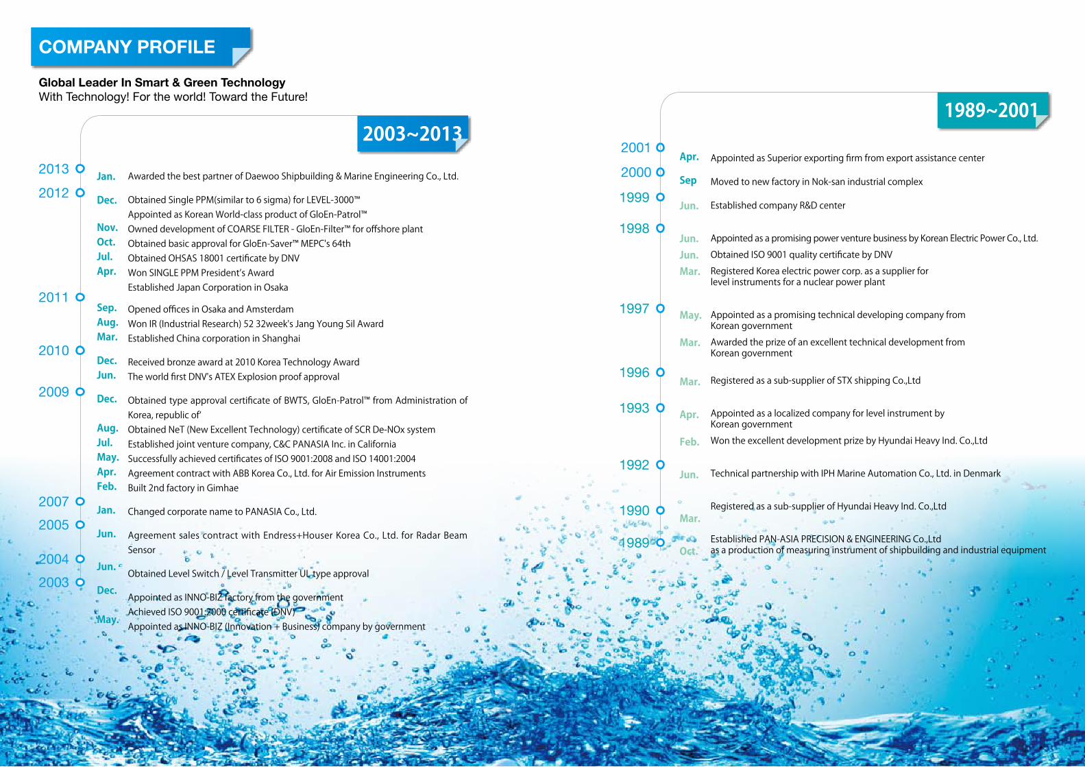
COMPANY PROFILE
2003~2013
Jan.
Dec.
Nov.Oct.Jul.Apr.
Sep.Aug.Mar.
Dec.Jun.
Dec.
Aug.Jul.May.Apr.Feb.
Jan.
Jun.
Jun.
Dec.May..
Awarded the best partner of Daewoo Shipbuilding & Marine Engineering Co., Ltd.
Obtained Single PPM(similar to 6 sigma) for LEVEL-3000™Appointed as Korean World-class product of GloEn-Patrol™Owned development of COARSE FILTER - GloEn-Filter™ for offshore plant Obtained basic approval for GloEn-Saver™ MEPC's 64thObtained OHSAS 18001 certificate by DNV Won SINGLE PPM President’s AwardEstablished Japan Corporation in Osaka
Opened offices in Osaka and AmsterdamWon IR (Industrial Research) 52 32week's Jang Young Sil Award Established China corporation in Shanghai
Received bronze award at 2010 Korea Technology AwardThe world first DNV's ATEX Explosion proof approval
Obtained type approval certificate of BWTS, GloEn-Patrol™ from Administration of Korea, republic of‘Obtained NeT (New Excellent Technology) certificate of SCR De-NOx system Established joint venture company, C&C PANASIA Inc. in CaliforniaSuccessfully achieved certificates of ISO 9001:2008 and ISO 14001:2004Agreement contract with ABB Korea Co., Ltd. for Air Emission InstrumentsBuilt 2nd factory in Gimhae
Changed corporate name to PANASIA Co., Ltd.
Agreement sales contract with Endress+Houser Korea Co., Ltd. for Radar Beam Sensor
Obtained Level Switch / Level Transmitter UL type approval
Appointed as INNO-BIZ factory from the governmentAchieved ISO 9001:2000 certificate (DNV)Appointed as INNO-BIZ (Innovation + Business) company by government
Global Leader In Smart & Green TechnologyWith Technology! For the world! Toward the Future!
2011
2010
2009
2001
2000
2012
2013
2007
2005
2004
2003
Appointed as Superior exporting firm from export assistance center
Moved to new factory in Nok-san industrial complex
Established company R&D center
Appointed as a promising power venture business by Korean Electric Power Co., Ltd.
Obtained ISO 9001 quality certificate by DNV
Registered Korea electric power corp. as a supplier for level instruments for a nuclear power plant
Appointed as a promising technical developing company from Korean government
Awarded the prize of an excellent technical development from Korean government
Registered as a sub-supplier of STX shipping Co.,Ltd
Appointed as a localized company for level instrument by Korean government
Won the excellent development prize by Hyundai Heavy Ind. Co.,Ltd
Technical partnership with IPH Marine Automation Co., Ltd. in Denmark
Registered as a sub-supplier of Hyundai Heavy Ind. Co.,Ltd
Established PAN-ASIA PRECISION & ENGINEERING Co.,Ltd as a production of measuring instrument of shipbuilding and industrial equipment
1989~2001
1999
1998
1997
1996
1993
1992
1990
1989
Apr.
Sep
Jun.
Jun.Jun.Mar.
May.
Mar.
Mar.
Apr.Feb.
Jun.
Mar.
Oct.

CEO MESSAGE
I’m Lee Soo-Tae, C.E.O. of Panasia.
Panasia, as a professional company specializing in environmental facilities such as a variety of ship’s automatic control & gauging equipment ship’s ballast water treatment systems, flue gas denitrogenization facilities and so on, has exported the best quality products to overseas companies as well as to domestic shipyards.
Especially, since established in 1989, Panasia has achieved outstanding success for 23 years, starting from technology developments in the field of ship’s draft sounding systems, and researches, developments, and commercialization of GloEn-Patrol™ to filter, sterilize, and process ship’s ballast water, most blamed for badly stirring up the marine ecology, and PaNOx™ to cut more than 80% of nitrogen oxide, blamed for global warming, with Panasia’s technologies and know-hows accumulated for the long time.
Panasia has spent whole time only in pursuit of developing creative power and indomitable spirit, while providing customers with best quality and efficient products by making investments lavishly in quality improvements and technology developments under the Panasia’s philosophy, “until customers are completely satisfied” and further, we are daringly going to take steps toward a goal to be a frontrunner to realize “the securing of world class competitive power in the field of marine equipment industry by developing a ground breaking technology”.
Now, Panasia proclaimed "SOAR 2020" and is making utmost efforts to be a top enterprise in a market share of the marine equipment industry. For reaching the goal, Panasia has solidified the global business management foundation by using its best system to meet demands from customers promptly and correctly and by building up the overseas networks by efficiently using local branch offices or agents placed in major cities and ports in the world, and hasn’t spared any effort in producing the best customer service, including on-time delivery through the efficient operation of ERP system. Furthermore, Panasia has been intensively running social commitment and contribution programs to develop a community-friendly corporate culture, not just stagnant cling to a short-sighted business profits, under the corporate social responsibility.
We are going to recreate the next 100 years of Panasia on the basis of business know-how and achievements Panasia has accumulated for the past 20 years. We boldly yet confidently pledge Panasia will grow up a leading enterprise to fully meet the demands of customers with the best quality products and services.Sincerely yours,
C.E.O. LeeSoo-TaeApril. 2013
Global Leader In Smart & Green TechnologyWith Technology! For the world! Toward the Future!
PANASIA is sailing to become first class
company is global management era with
research and development.
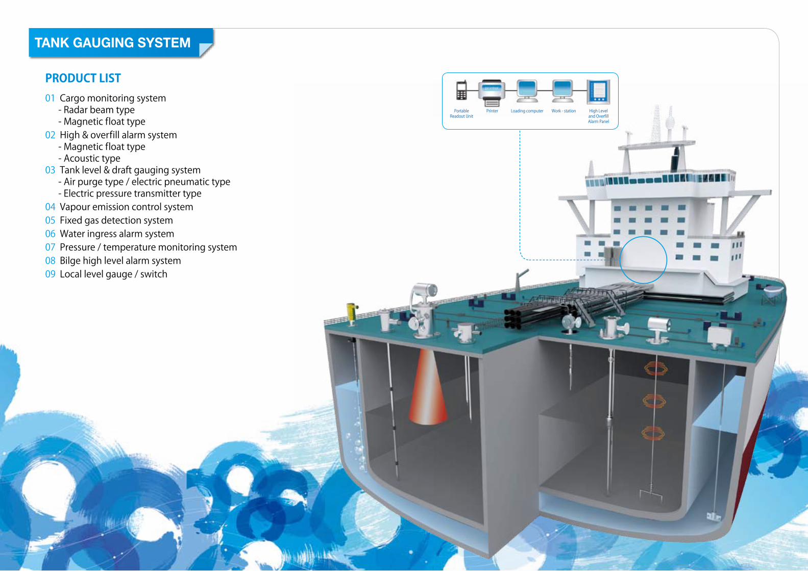
PRODUCTLIST01 Cargo monitoring system - Radar beam type - Magnetic float type02 High & overfill alarm system - Magnetic float type - Acoustic type03 Tank level & draft gauging system - Air purge type / electric pneumatic type - Electric pressure transmitter type04 Vapour emission control system05 Fixed gas detection system06 Water ingress alarm system07 Pressure / temperature monitoring system08 Bilge high level alarm system09 Local level gauge / switch
PortableReadout Unit
Printer Loading computer Work - station High Level and OverfillAlarm Panel
TANK GAUGING SYSTEM

CARGO MONITORINGSYSTEM

12
INTRODUCTION Radar beam type cargo tank monitoring system is especially designed be integrated cargo monitoring system for inland river or ocean going vessels and tank barge. It is based on the utilization of smart sensors, including microprocessors performing signal processing and offer, in addition to transmitting tank level, pressure, and temperature data to the central monitoring system, capabilities such as self-diagnostics, self-monitoring and remote configuring. These capabilities allow for predictive maintenance owing to the continuous tracking of performance drift.
Radar beam type cargo tank monitoring system is a ‘downward-looking’ measuring system, operating based on the time-of-flight method. It measures the distance from the reference point(process connection)to the product surface. Radar impulses are emitted by an antenna, reflected off the product surface and received again by the radar system.
OPERATING PRINCIPLE
FEATURES
TECHNICAL SPECIFICATION
- 2 WIRE TECHNOLOGY, GOOD PRICE. A real alternative to differential pressure, floats and displacers. 2-wire technology reduces wiring cost and allows easy implementation into existing systems.- NON CONTACT MEASUREMENT. Measurement is almost independent from product properties.- Easy on-site operation via menu-driven alphanumeric display.- Easy commissioning, documentation and diagnostics via operating software- 2 FREQUENCY RANGES-26GHz. No compromises, the right frequency for every application.- HART or PROFIBUS PA respectively foundation fieldbus protocol.
MEASURING RANGE Up to 40m depending on installation, product, surface conditions and antenna size.
OUTPUT 4…20, HART PROFIBUS PA, foundation fieldbus.
MEASURING ACCURACY ±3mm (up to 10mm)
MEASURING CYCLE 1 sec
CERTIFICATION ATEX II ½ G EEX ia II C T6ATEX II ½ G EEX d[ia] II C T6
PRODUCT TEMPERATURE -40°C to 150°C
PRESSURE From vacuum to 40 bar
PROCESS CONNECTION 1 ½ “thread DN50(2”) .. DN150 (6”) flange
MAJOR MATERIAL SUS 316
BEAM ANGLE 8°
WEIGHT 20
OUTLINE / DIMENSIONS
CONTROL PANEL
N0N-HAZARDOUS AREAHAZARDOUS AREA
CARGO CONTROL ROOM
I.S BARRIER
CARGO MONITORING SYS.
NPNP NP NP NP NP
TEMP. SENSOR(3POINTS)
RADAR SENSORPRESSURE SENSOR
3 pair-shield cableRS485/RS422 232
TO : A.M.S
POWER FAIL ALARMDRY CONTACT / NC
COMMON ALARMDRY CONTACT / NC
POWER SOURCE-AC220V
ELECTRIC HORN WITH LIGHTFOR OVERFILL/RED 1SET
POWER SOURCE-AC220V
ELECTRIC HORN WITH LIGHTFOR HIGH/YELLOW 1SET
CONTINUOUS POWER SUPPLY FOR C.M.SAC220V 1Ø 60Hz
TANK OVERFILL ALARMALARM MONITOR
HIGH LEVEL ALARMAU-2030A
2 pair-shield cable
RS485/RS422 TO : LOADING COM.
2 pair-shield cableHIGH & OVERFILLALARM SENSOR
DPYCY-2.5
T/B
BALLAST & E/R TANK LEVEL4~20mA
POWER
Primary
Secondary
BUZZERSTOP
FLICKERSTOP
BUZZER
BUZZER/LAMPTEST
ALARM MONITOR AU-2030A
POWER
Primary
Secondary
BUZZERSTOP
FLICKERSTOP
BUZZER
BUZZER/LAMPTEST
PROTECTION PIPE
BEAM
Level SwitchTOP
Model PR-30EX-2
Cert. No. DNV A-9453
Mfg. Date 200 . . .
Serial No.
Application
07 - LS
HIGH & OVERFILL
Tank Name
COMPUTERMONITORING
CARGO MONITORING
SYSTEM
TANK LEVEL
GAUGING SYSTEM
ALARM SYSTEM
LEVEL GAUGE
LEVEL SWITCH
OTHERS
MICROPLOT M FMR 240(Horn type) LEVELFLEX M FMP40(Guided wire type)
Global Leader In Smart & Green Technology PANASIA CO.,LTD. 13
Radar Beam Type Cargo Tank Monitoring System
CARGO MONITORING SYSTEM01

14
INTRODUCTION Tank monitoring system, named as PATROL 3 2.0™ system is a magnetic float type tank level gauge featuring an all-in-one detector that measures tank level, temperature, vapor pressure, as well as issuing alarm when limits are exceeded. It monitors these tank conditions on various display units. Information on ballast tanks, fuel oil tanks, and draft gauges, as well as cargo tanks can be comprehensively utilized by integrated ship operation control system via a loading computer. A key feature of this system is its ease of handling, because the sensors in the detector are flexible, it can be lifted up by hand without the need to enter tanks, even in the case of cargo tanks of crude oil tanker, product oil tanker, chemical carrier for repair and maintenance. Likewise, transportation and fitting of the tank monitoring system is also simple. For LNG carrier, this magnetic float type tank level gauge is usually provided in W.B.T & draft gauge system and F.O. tank level gauge system.
Sets of reed switches are positioned along the length of the guide pipe. As the float travels up and down the guide pipe in accordance with the level of the liquid in the tank, the flux emitted from magnets within the float works upon the reed switches on or off. By measuring voltage across the transmitter circuit, the level of the liquid can be calculated according to the changes in circuit resistance. The converted signal is sent to the control box via I.S. barrier in the control room or to a local indicator as the case may be.
OPERATING PRINCIPLE
TECHNICAL SPECIFICATION TYPE Reed switch with magnetic float
ANTI-EXPLOSION STRUCTURE EX ia II C T6
MEASURING RANGE 50m, Max
SPECIFIC GRAVITY 0.5 and above (of liquid in tank)
VISCOSITY 15,000 sec. redwood No.1 Max
DETECTING ACCURACY ± 25
ALLOWABLE TEMPERATURE -40 … +120°C
ALLOWABLE PRESSURE 3 f/
TYPE 1 Two-terminal IC, temp, transducer
MEASURING RANGE -55 / + 150°C
DETECTING ACCURACY ± 2°C
TYPE 2 PT 100 ohm
MEASURING RANGE -50°C ~ +200°C
SENSOR TOLERANCE EN 60751 class B
OUTLINE / DIMENSIONS
OUTLINE / DIMENSIONS
SAFETY AREAHAZARDOUS AREA
CARGO MONITORING
SYSTEM
TANK LEVEL
GAUGING SYSTEM
ALARM SYSTEM
LEVEL GAUGE
LEVEL SWITCH
OTHERS
Dream & Tomorrow PANASIA CO.,LTD. 15
Magnetic Float Type Cargo Tank Monitoring System
CARGO MONITORING & CONTROL SYSTEM01
LEVEL DETECTING PART
TEMPERATURE DETECTING PART
Cargo Monitoring ConsoleInstallation ofBottom Support
Local Indicator
Tank Top
Application
· Crude oil· Product oil· Chemicals· Sea Water· Fresh Water
Level/Temp./I.G.Pressure Transmitter

TANK LEVEL
GAUGING SYSTEM
Mode
Analog Interface Module
Set
PA-1100
1. +11.0023. +25.0015. +12.0117. +11.112
2. +11.0024. +25.0016. +12.0118. +11.112
TANK NAME
OUTPUT = 4 to 20mASERIAL NO.:PA09-PAPT-XXXX
CERT.NO : EX08IS077Tamb : -25°c to +85°cEx ia IIC T4
LEVEL 3000 - LEVEL TRANSMITTERUi = 30V
Ci = 0.05 + 0.12nF/mLi = 0.2mH + 0.001mH/m
Pi = 0.75WIi = 100mA
TAG NO. :
RS-485
4-20mA
MODULE & DISPLAY
- TOP POLE TYPE - - TOP INTERNAL TYPE - - SIDE TYPE - - DRAFT MEASUREMENT -
NAMETANK
NAMETANK
NAMETANK
NAMETANK
NAMETANK
NAMETANK
NAMETANK
NAMETANK
NAMETANK
NAMETANK
NAMETANK
NAMETANK
NAMETANK
NAMETANK
NAMETANK
NAMETANK
NAMETANK
NAMETANK
NAMETANK
NAMETANK
NAMETANK
NAMETANK
NAMETANK
NAMETANK
NAMETANK
NAMETANK
NAMETANK
NAMETANK
NAMETANK
m
m
m
m
m
m
m
m
m
m
m
m
m
m
m
m
m
m
m
m
m
m
m
m
m
m
m
m
m
m
DEAD ZONE
DEAD ZONE
DEAD ZONE
DEAD ZONE
DEAD ZONE
40
40
40
D1014D
DMT 01 ATEX
Ex
G
E 042 X
II (1) G D II (1) G DEx[EEx ia] IIC
E 042 X
DMT 01 ATEX
[EEx ia] IIC
G
PWR ON
D1014D
PWR ON
II (1) G DEx[EEx ia] IIC
E 042 X
DMT 01 ATEX
G
PWR ON
D1014D
II (1) G DEx[EEx ia] IIC
E 042 X
DMT 01 ATEX
G
PWR ON
D1014D
ANALOG INTERFACE
(4-20mA to RS-485)
I.S BARRIER
MONITORING COMPUTER
MIN.120
DRY/VOIDSPACES
DRY/VOIDSPACES
100
VENT HOLE
WEATHER DECK
PNIK(+)
GREEN(-)
WHITE(A)
YELLOW(B)
+
-
JUNCTION BOX
SHIELD SHIELD
B
EA
-+
-
T+T-
BROWN(T+)
GRAY(T-)
BREATH TUBE(CUTOUT)
I.D(1)xO.D(2.5)SILICON TUBE
PT1/4" FITTINGFOR BREATHER
+
-
AE-+
T/BPNIK(+)
GREEN(-)
WHITE(A)
YELLOW(B) FOR TEST
(4~20mA)TO USER CONNECTION
B
YELLOW/GREEN[or GRAY]
For Temperature (3-Wire)
T-T+
( PT100 ohm )TO USER CONNECTION
BROWN
GRAY
4-20mA LOOP POWER
TO BE SUPPLIED BY USER
- CONNECTION ON JUNCTION BOX -
TANK NAME
OUTPUT = 4 to 20mASERIAL NO.:PA09-PAPT-XXXX
CERT.NO : EX08IS077Tamb : -25°c to +85°cEx ia IIC T4LEVEL-3000 LEVEL TRANSMITTER
Ui = 30V
Ci = 0.05 + 0.12nF/mLi = 0.2mH + 0.001mH/m
Pi = 0.75WIi = 100mA
TAG NO. :
TRANSMITTER
75
110
USER CABLE
- OUTLINE/DIMENSION -
SHIELD
HEX.27
APPROX.190
6
25.4
25.6
SYSTEM DIAGRAM AND INSTALLATION METHOD
Electric Pressure TypeLevel Transmitter (LEVEL-3000™)
TANK LEVEL GAUGING SYSTEM02
18
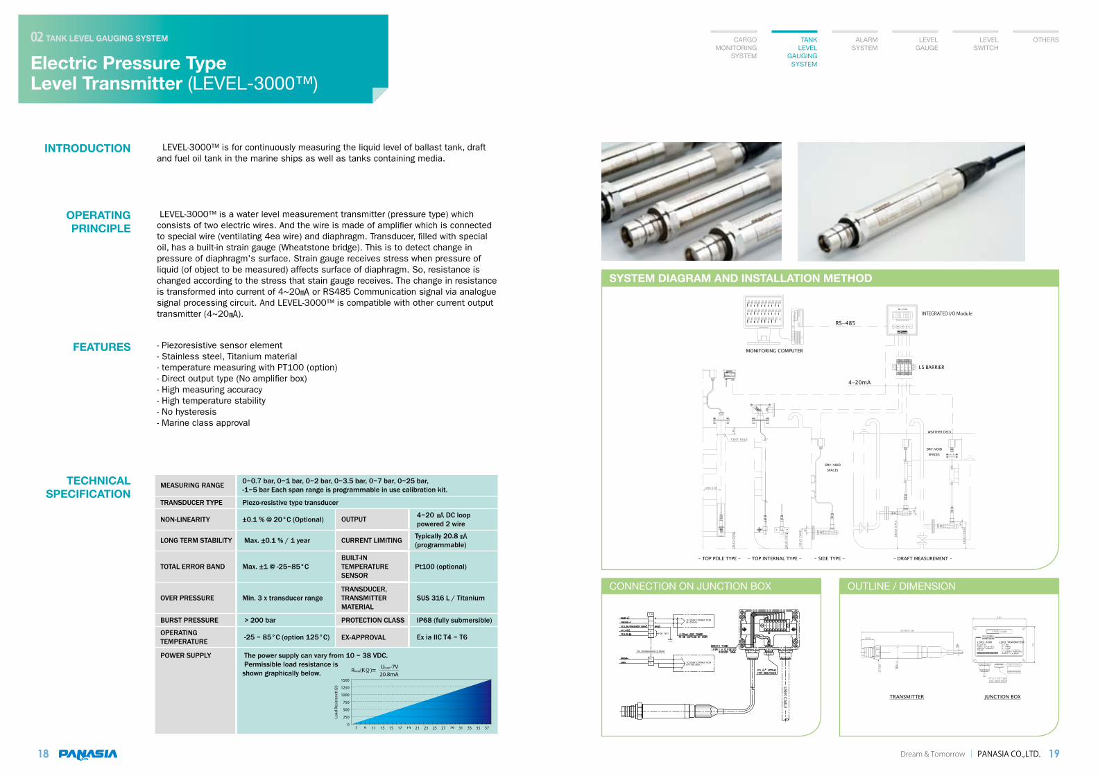
INTRODUCTION LEVEL-3000™ is for continuously measuring the liquid level of ballast tank, draft and fuel oil tank in the marine ships as well as tanks containing media.
LEVEL-3000™ is a water level measurement transmitter (pressure type) which consists of two electric wires. And the wire is made of amplifier which is connected to special wire (ventilating 4ea wire) and diaphragm. Transducer, filled with special oil, has a built-in strain gauge (Wheatstone bridge). This is to detect change in pressure of diaphragm's surface. Strain gauge receives stress when pressure of liquid (of object to be measured) affects surface of diaphragm. So, resistance is changed according to the stress that stain gauge receives. The change in resistance is transformed into current of 4~20 or RS485 Communication signal via analogue signal processing circuit. And LEVEL-3000™ is compatible with other current output transmitter (4~20).
- Piezoresistive sensor element- Stainless steel, Titanium material- temperature measuring with PT100 (option)- Direct output type (No amplifier box)- High measuring accuracy- High temperature stability- No hysteresis- Marine class approval
OPERATING PRINCIPLE
TECHNICAL SPECIFICATION
FEATURES
Dream & Tomorrow PANASIA CO.,LTD. 19
CARGO MONITORING
SYSTEM
TANK LEVEL
GAUGING SYSTEM
ALARM SYSTEM
LEVEL GAUGE
LEVEL SWITCH
OTHERS
MEASURING RANGE 0~0.7 bar, 0~1 bar, 0~2 bar, 0~3.5 bar, 0~7 bar, 0~25 bar, -1~5 bar Each span range is programmable in use calibration kit.
TRANSDUCER TYPE Piezo-resistive type transducer
NON-LINEARITY ±0.1 % @ 20°C (Optional) OUTPUT 4~20 DC loop powered 2 wire
LONG TERM STABILITY Max. ±0.1 % / 1 year CURRENT LIMITING Typically 20.8 (programmable)
TOTAL ERROR BAND Max. ±1 @ -25~85°CBUILT-IN TEMPERATURE SENSOR
Pt100 (optional)
OVER PRESSURE Min. 3 x transducer rangeTRANSDUCER, TRANSMITTER MATERIAL
SUS 316 L / Titanium
BURST PRESSURE > 200 bar PROTECTION CLASS IP68 (fully submersible)
OPERATING TEMPERATURE -25 ~ 85°C (option 125°C) EX-APPROVAL Ex ia IIC T4 ~ T6
POWER SUPPLY The power supply can vary from 10 ~ 38 VDC. Permissible load resistance is shown graphically below.
Mode
Analog Interface Module
Set
PA-1100
1. +11.0023. +25.0015. +12.0117. +11.112
2. +11.0024. +25.0016. +12.0118. +11.112
TANK NAME
OUTPUT = 4 to 20mASERIAL NO.:PA09-PAPT-XXXX
CERT.NO : EX08IS077Tamb : -25°c to +85°cEx ia IIC T4
LEVEL 3000 - LEVEL TRANSMITTERUi = 30V
Ci = 0.05 + 0.12nF/mLi = 0.2mH + 0.001mH/m
Pi = 0.75WIi = 100mA
TAG NO. :
RS-485
4-20mA
MODULE & DISPLAY
- TOP POLE TYPE - - TOP INTERNAL TYPE - - SIDE TYPE - - DRAFT MEASUREMENT -
NAMETANK
NAMETANK
NAMETANK
NAMETANK
NAMETANK
NAMETANK
NAMETANK
NAMETANK
NAMETANK
NAMETANK
NAMETANK
NAMETANK
NAMETANK
NAMETANK
NAMETANK
NAMETANK
NAMETANK
NAMETANK
NAMETANK
NAMETANK
NAMETANK
NAMETANK
NAMETANK
NAMETANK
NAMETANK
NAMETANK
NAMETANK
NAMETANK
NAMETANK
m
m
m
m
m
m
m
m
m
m
m
m
m
m
m
m
m
m
m
m
m
m
m
m
m
m
m
m
m
m
DEAD ZONE
DEAD ZONE
DEAD ZONE
DEAD ZONE
DEAD ZONE
40
40
40
D1014D
DMT 01 ATEX
Ex
G
E 042 X
II (1) G D II (1) G DEx[EEx ia] IIC
E 042 X
DMT 01 ATEX
[EEx ia] IIC
G
PWR ON
D1014D
PWR ON
II (1) G DEx[EEx ia] IIC
E 042 X
DMT 01 ATEX
G
PWR ON
D1014D
II (1) G DEx[EEx ia] IIC
E 042 X
DMT 01 ATEX
G
PWR ON
D1014D
ANALOG INTERFACE
(4-20mA to RS-485)
I.S BARRIER
MONITORING COMPUTER
MIN.120
DRY/VOIDSPACES
DRY/VOIDSPACES
100
VENT HOLE
WEATHER DECK
PNIK(+)
GREEN(-)
WHITE(A)
YELLOW(B)
+
-
JUNCTION BOX
SHIELD SHIELD
B
EA
-+
-
T+T-
BROWN(T+)
GRAY(T-)
BREATH TUBE(CUTOUT)
I.D(1)xO.D(2.5)SILICON TUBE
PT1/4" FITTINGFOR BREATHER
+
-
AE-+
T/BPNIK(+)
GREEN(-)
WHITE(A)
YELLOW(B) FOR TEST
(4~20mA)TO USER CONNECTION
B
YELLOW/GREEN[or GRAY]
For Temperature (3-Wire)
T-T+
( PT100 ohm )TO USER CONNECTION
BROWN
GRAY
4-20mA LOOP POWER
TO BE SUPPLIED BY USER
- CONNECTION ON JUNCTION BOX -
TANK NAME
OUTPUT = 4 to 20mASERIAL NO.:PA09-PAPT-XXXX
CERT.NO : EX08IS077Tamb : -25°c to +85°cEx ia IIC T4LEVEL-3000 LEVEL TRANSMITTER
Ui = 30V
Ci = 0.05 + 0.12nF/mLi = 0.2mH + 0.001mH/m
Pi = 0.75WIi = 100mA
TAG NO. :
TRANSMITTER
75
110
USER CABLE
- OUTLINE/DIMENSION -
SHIELD
HEX.27
APPROX.190
6
25.4
25.6
CONNECTION ON JUNCTION BOX OUTLINE / DIMENSION
INTEGRATED I/O Module
20
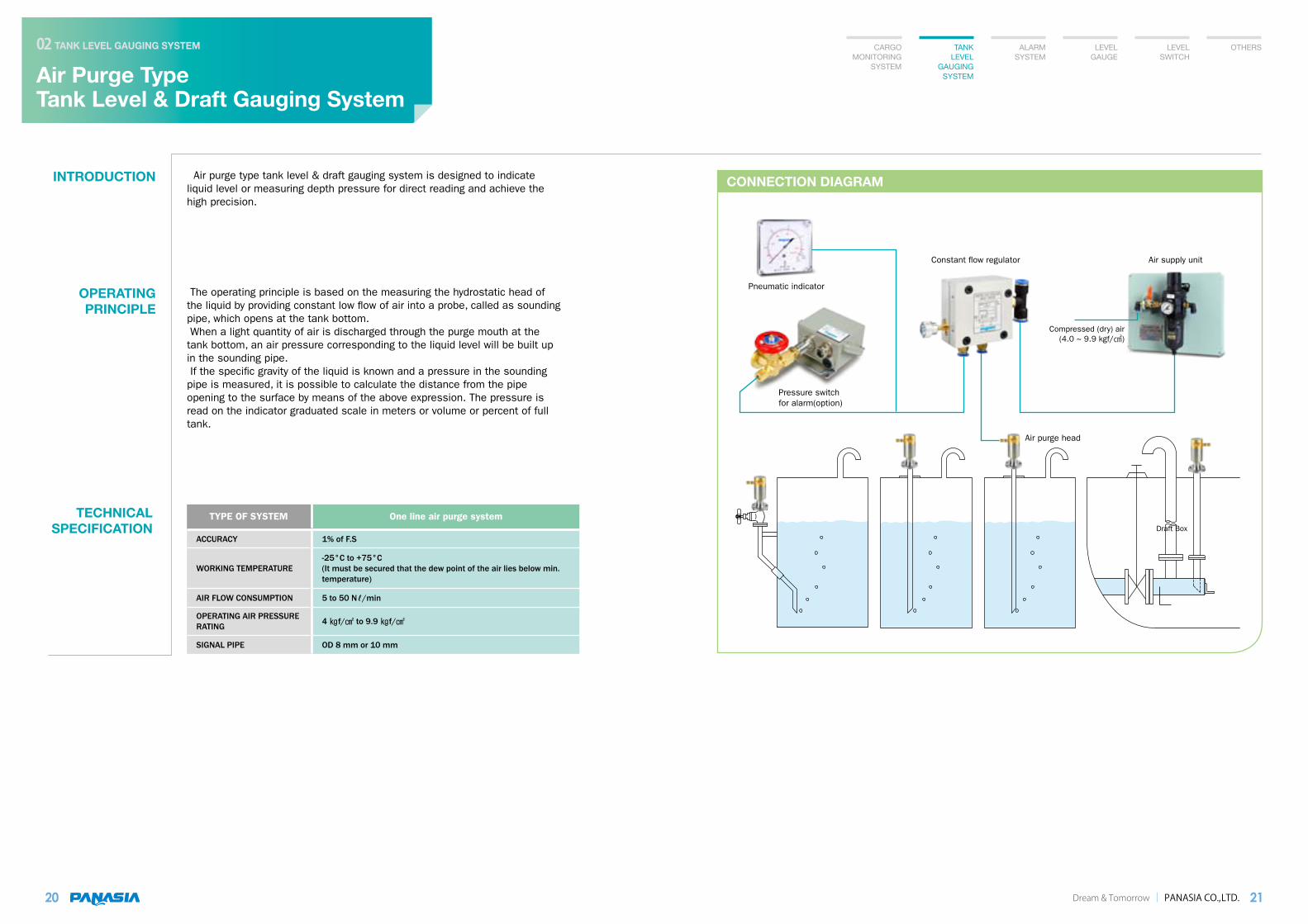
INTRODUCTION Air purge type tank level & draft gauging system is designed to indicate liquid level or measuring depth pressure for direct reading and achieve the high precision.
The operating principle is based on the measuring the hydrostatic head of the liquid by providing constant low flow of air into a probe, called as sounding pipe, which opens at the tank bottom. When a light quantity of air is discharged through the purge mouth at the tank bottom, an air pressure corresponding to the liquid level will be built up in the sounding pipe. If the specific gravity of the liquid is known and a pressure in the sounding pipe is measured, it is possible to calculate the distance from the pipe opening to the surface by means of the above expression. The pressure is read on the indicator graduated scale in meters or volume or percent of full tank.
OPERATING PRINCIPLE
TECHNICAL SPECIFICATION
TYPE OF SYSTEM One line air purge system
ACCURACY 1% of F.S
WORKING TEMPERATURE-25°C to +75°C(It must be secured that the dew point of the air lies below min. temperature)
AIR FLOW CONSUMPTION 5 to 50 Nℓ/min
OPERATING AIR PRESSURE RATING 4 f/ to 9.9 f/
SIGNAL PIPE OD 8 mm or 10 mm
CARGO MONITORING
SYSTEM
TANK LEVEL
GAUGING SYSTEM
ALARM SYSTEM
LEVEL GAUGE
LEVEL SWITCH
OTHERS
Dream & Tomorrow PANASIA CO.,LTD. 21
Air Purge Type Tank Level & Draft Gauging System
TANK LEVEL GAUGING SYSTEM02
CONNECTION DIAGRAM
Pneumatic indicator
Pressure switch for alarm(option)
Constant flow regulator
Air purge head
Air supply unit
Draft Box
Compressed (dry) air (4.0 ~ 9.9 kgf/)

The upgraded P/I converts are provided to converter an pneumatic pressure into an electronic signal for remote display of tank level and draft gauge on CRT and / or electric indicator. Unlike the pneumatic indicator possible to be damaged by excess-pressure, this P/I converter is free from inlet excess-pressure without even gauge saver.
MODEL P 940
OUTPUT CURRENT 4 to 20 DC,2 wire system
PROTECTION against inlet excess-pressure.
CONNECTION DIAGRAM
Electric Pneumatic Type Tank Level & Draft Gauging System
TANK LEVEL GAUGING SYSTEM02
22
INTRODUCTION Electric pneumatic type tank level & draft gauging system is designed to indicate liquid level or measuring depth pressure for direct reading and achieve the high precision.
Electric pneumatic type tank level & draft gauging system is widely used for ballast tank level measurement, draft measurement and engine room tank level measurement, etc.
OPERATING PRINCIPLE
APPLICATION
P/I CONVERTER
Dream & Tomorrow PANASIA CO.,LTD. 23
CARGO MONITORING
SYSTEM
TANK LEVEL
GAUGING SYSTEM
ALARM SYSTEM
LEVEL GAUGE
LEVEL SWITCH
OTHERS
LEVEL INDICATING PANEL
P/I CONVERTER
The operating principle is basically the same as the level measurement of air purge type tank level monitoring system. But electric pneumatic type tank level gauging system has electric reading and P/I converter that converts pneumatic input signal to 4-20 output signal in addition to air purge type system.
Monitoring Computer
P/I converter
Air supply unit
Constant flow regulator
Air purge head
Draft Box
Electric indicator
RS-485
4-20mA
4-20mA
Integrated I/O module
Alarm / Display unit
CONNECTION DIAGRAM
High Precision Electric Pneumatic TypeLevel Transmitter
TANK LEVEL GAUGING SYSTEM02
24
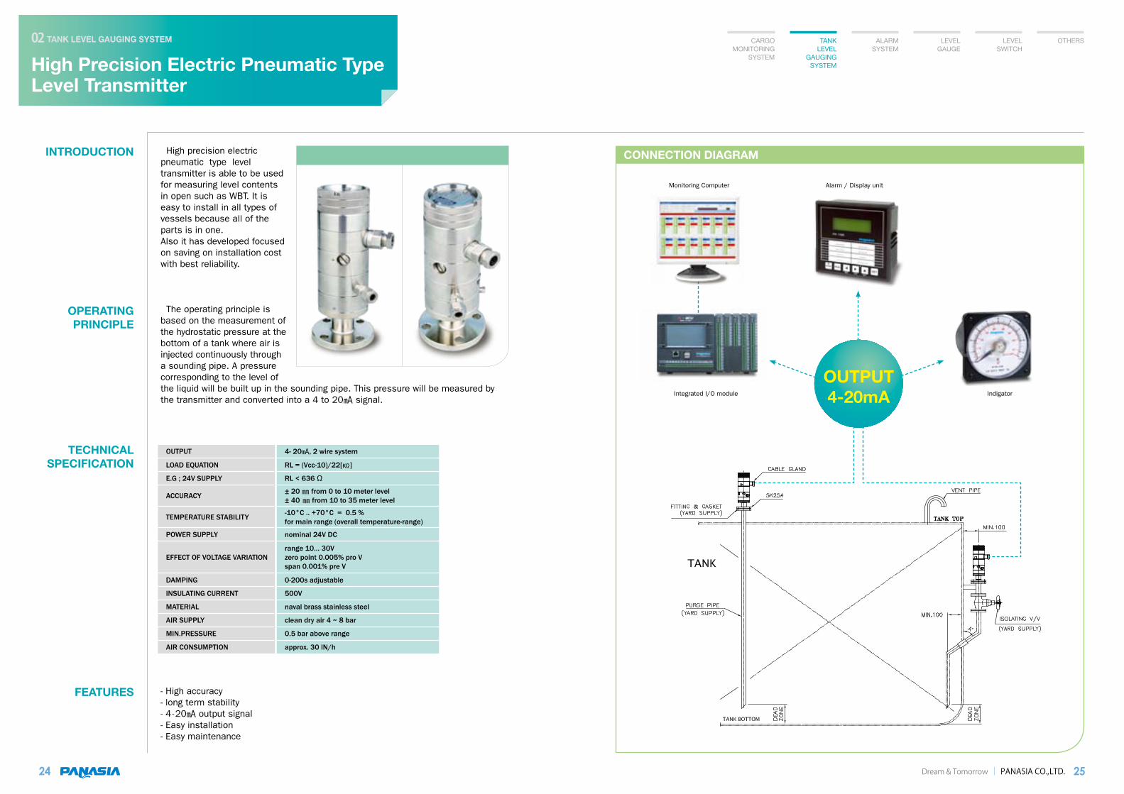
INTRODUCTION High precision electric pneumatic type level transmitter is able to be used for measuring level contents in open such as WBT. It is easy to install in all types of vessels because all of the parts is in one. Also it has developed focused on saving on installation cost with best reliability.
OPERATING PRINCIPLE
TECHNICAL SPECIFICATION
FEATURES
Dream & Tomorrow PANASIA CO.,LTD. 25
CARGO MONITORING
SYSTEM
TANK LEVEL
GAUGING SYSTEM
ALARM SYSTEM
LEVEL GAUGE
LEVEL SWITCH
OTHERS
The operating principle is based on the measurement of the hydrostatic pressure at the bottom of a tank where air is injected continuously through a sounding pipe. A pressure corresponding to the level of the liquid will be built up in the sounding pipe. This pressure will be measured by the transmitter and converted into a 4 to 20 signal.
- High accuracy- long term stability- 4-20 output signal- Easy installation- Easy maintenance
Integrated I/O module
Monitoring Computer
Indigator
OUTPUT 4- 20, 2 wire system
LOAD EQUATION RL = (Vcc-10)/22[]
E.G ; 24V SUPPLY RL < 636 Ω
ACCURACY ± 20 from 0 to 10 meter level± 40 from 10 to 35 meter level
TEMPERATURE STABILITY -10°C .. +70°C = 0.5 %for main range (overall temperature-range)
POWER SUPPLY nominal 24V DC
EFFECT OF VOLTAGE VARIATIONrange 10… 30Vzero point 0.005% pro Vspan 0.001% pre V
DAMPING 0-200s adjustable
INSULATING CURRENT 500V
MATERIAL naval brass stainless steel
AIR SUPPLY clean dry air 4 ~ 8 bar
MIN.PRESSURE 0.5 bar above range
AIR CONSUMPTION approx. 30 lN/h
Alarm / Display unit
OUTPUT4-20mA
MEASURING RANGE 0 ~ 30m H2O
AIR SUPPLY 1.4 bar or minimum 1.2 x measuring range
AIR CONSUMPTION at 1.4 bar air supply approx. 30l/h
VISCOSITY at 2.5 bar air supply approx. 40l/h = 3,500 redwood 1 sec
TOLERANCES
(measured with water) Including reaction sensitivity and hysteresis at 1.4 bar. at empty tank and free discharge nozzle : max.25 > 0.1 m tank level measured from middle of diaphragm : max.±25 , ±0.75% The O-point drift depends on the pressure loss caused by possible hose, tube mounted on the discharge nozzle.
TEMPERATURE RANGE RASPONSE TIME
0 to +80°C (4bar) Depends on tube dimension and tube length from pressure converter to indicating instrument as well as supply.
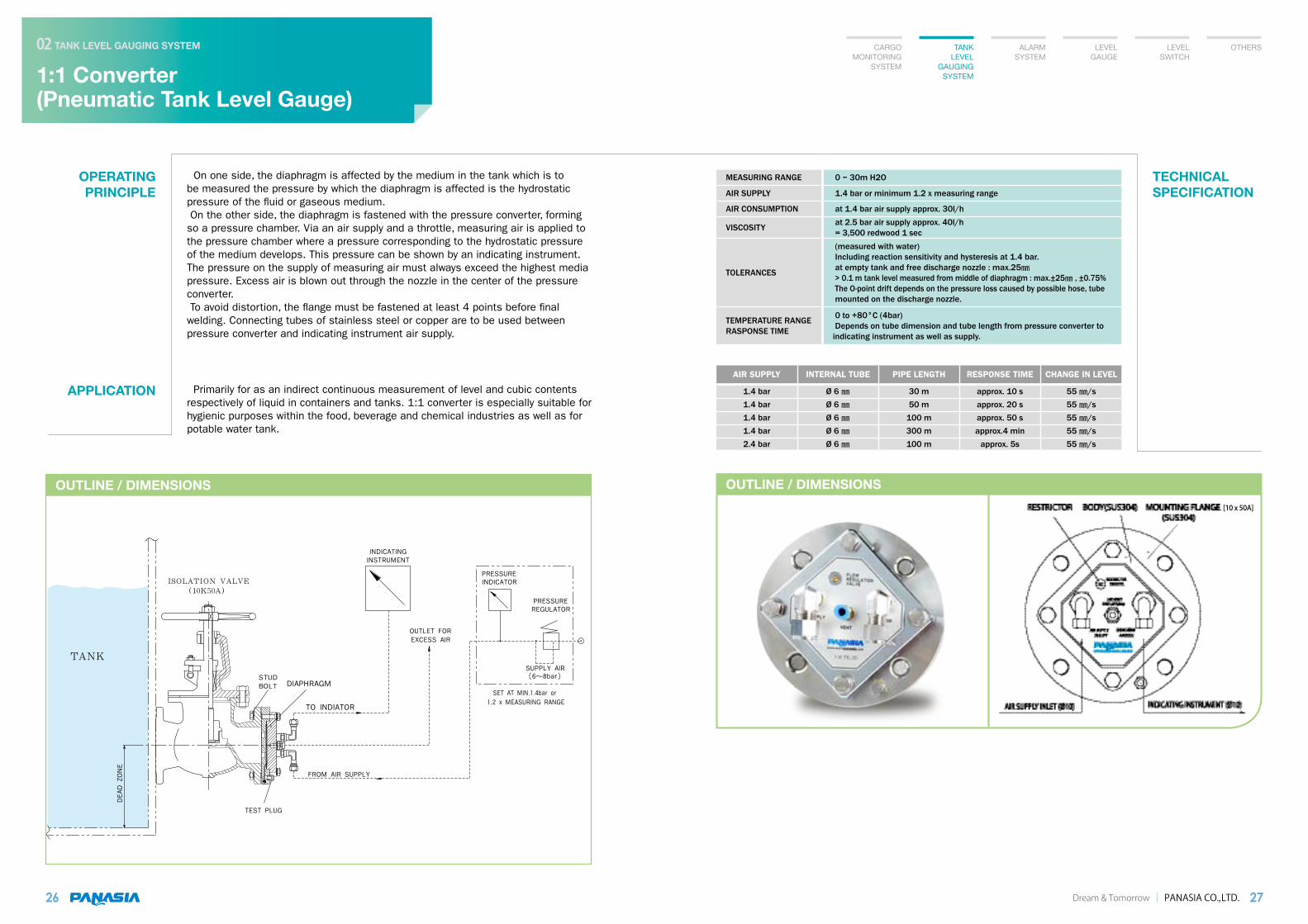
On one side, the diaphragm is affected by the medium in the tank which is to be measured the pressure by which the diaphragm is affected is the hydrostatic pressure of the fluid or gaseous medium. On the other side, the diaphragm is fastened with the pressure converter, forming so a pressure chamber. Via an air supply and a throttle, measuring air is applied to the pressure chamber where a pressure corresponding to the hydrostatic pressure of the medium develops. This pressure can be shown by an indicating instrument. The pressure on the supply of measuring air must always exceed the highest media pressure. Excess air is blown out through the nozzle in the center of the pressure converter. To avoid distortion, the flange must be fastened at least 4 points before final welding. Connecting tubes of stainless steel or copper are to be used between pressure converter and indicating instrument air supply.
OPERATING PRINCIPLE
26
APPLICATION Primarily for as an indirect continuous measurement of level and cubic contents respectively of liquid in containers and tanks. 1:1 converter is especially suitable for hygienic purposes within the food, beverage and chemical industries as well as for potable water tank.
TECHNICAL SPECIFICATION
OUTLINE / DIMENSIONSOUTLINE / DIMENSIONS
CARGO MONITORING
SYSTEM
TANK LEVEL
GAUGING SYSTEM
ALARM SYSTEM
LEVEL GAUGE
LEVEL SWITCH
OTHERS
Dream & Tomorrow PANASIA CO.,LTD. 27
1:1 Converter (Pneumatic Tank Level Gauge)
TANK LEVEL GAUGING SYSTEM02
AIR SUPPLY INTERNAL TUBE PIPE LENGTH RESPONSE TIME CHANGE IN LEVEL
1.4 bar1.4 bar1.4 bar1.4 bar2.4 bar
Ø 6 Ø 6 Ø 6 Ø 6 Ø 6
30 m50 m
100 m300 m100 m
approx. 10 sapprox. 20 sapprox. 50 sapprox.4 min
approx. 5s
55 /s55 /s55 /s55 /s55 /s
[10 x 50A]

ALARM SYSTEM
Magnetic Float TypeHigh & Overfill Alarm System
ALARM SYSTEM03
30
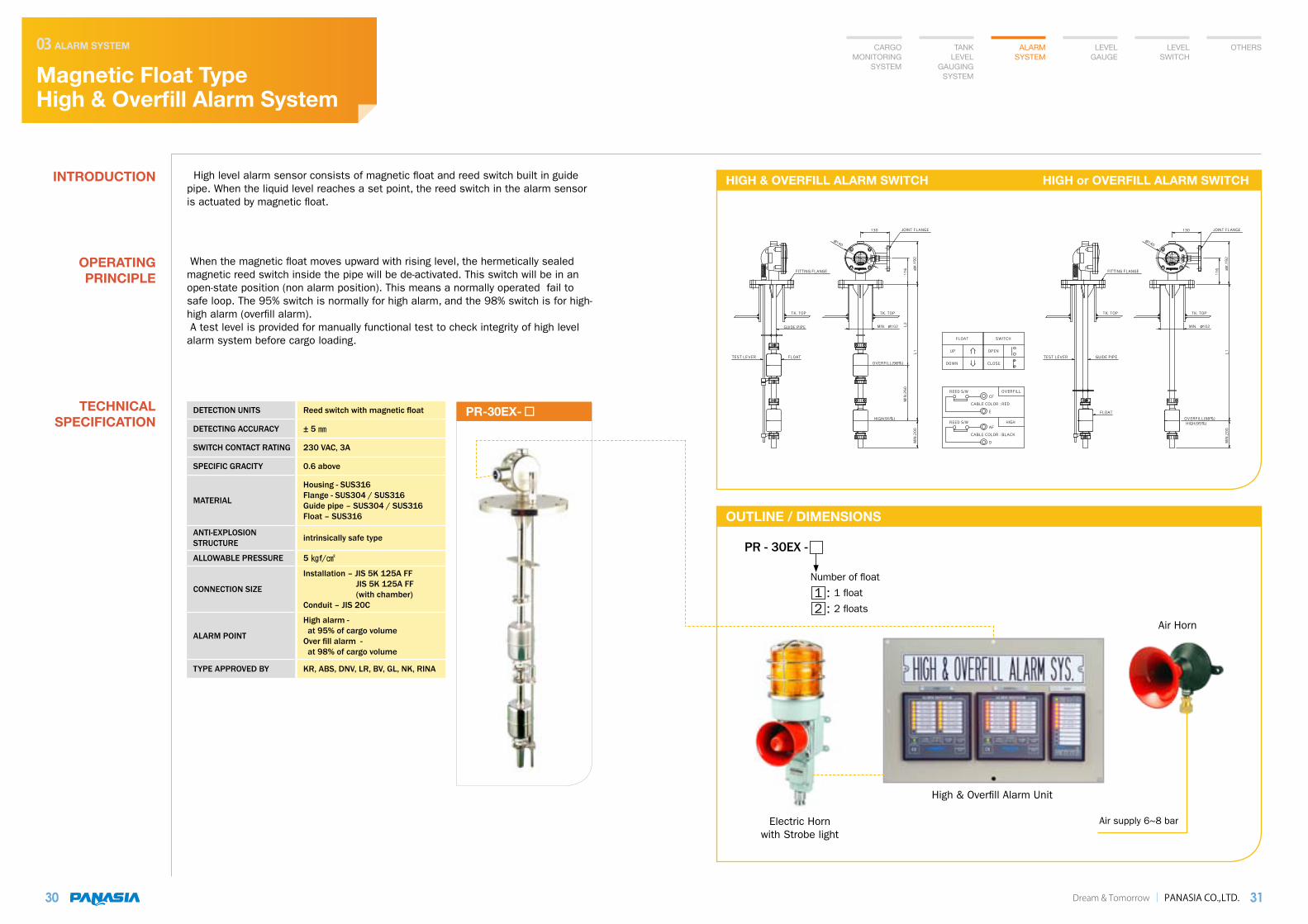
INTRODUCTION High level alarm sensor consists of magnetic float and reed switch built in guide pipe. When the liquid level reaches a set point, the reed switch in the alarm sensor is actuated by magnetic float.
When the magnetic float moves upward with rising level, the hermetically sealed magnetic reed switch inside the pipe will be de-activated. This switch will be in an open-state position (non alarm position). This means a normally operated fail to safe loop. The 95% switch is normally for high alarm, and the 98% switch is for high-high alarm (overfill alarm). A test level is provided for manually functional test to check integrity of high level alarm system before cargo loading.
OPERATING PRINCIPLE
TECHNICAL SPECIFICATION
Dream & Tomorrow PANASIA CO.,LTD. 31
CARGO MONITORING
SYSTEM
TANK LEVEL
GAUGING SYSTEM
ALARM SYSTEM
LEVEL GAUGE
LEVEL SWITCH
OTHERS
PR-30EX-DETECTION UNITS Reed switch with magnetic float
DETECTING ACCURACY ± 5
SWITCH CONTACT RATING 230 VAC, 3A
SPECIFIC GRACITY 0.6 above
MATERIAL
Housing - SUS316Flange - SUS304 / SUS316Guide pipe – SUS304 / SUS316Float – SUS316
ANTI-EXPLOSION STRUCTURE intrinsically safe type
ALLOWABLE PRESSURE 5 f/
CONNECTION SIZE
Installation – JIS 5K 125A FF JIS 5K 125A FF (with chamber)Conduit – JIS 20C
ALARM POINT
High alarm - at 95% of cargo volumeOver fill alarm - at 98% of cargo volume
TYPE APPROVED BY KR, ABS, DNV, LR, BV, GL, NK, RINA
OUTLINE / DIMENSIONS
HIGH & OVERFILL ALARM SWITCH HIGH or OVERFILL ALARM SWITCH
High & Overfill Alarm Unit
Air supply 6~8 barElectric Horn with Strobe light
Air Horn
PR - 30EX -
Number of float
1 : 1 float
2 : 2 floats

SAFETY AREAHAZARDOUS AREA
BOXI.S BARRIER
F.P.TKNO.9 CARGOHOLD
NO.8 CARGOHOLD
NO.2 CARGOHOLD
STOREBOSUN
NO.1 CARGOHOLD
SPACEVOID
ABNOMAL ALARM(DRY CONTACT : NC)COMMON ALARM(PRE)
BACKUP POWER SOURCE DC24V
POWER SOURCE AC220V 60Hz1ØCOMMON ALARM(MAIN)
2 CORE SHIELD
37 CORE SHIELD
2 CORE SHIELD
IN WHEEL HOUSEMASTER PANEL
PRET
T
E
P
O
S
T
T
I N
MAINT
T
E
P
O
S
T
T
I N
T
T
E
P
O
S
T
T
I N
PAN-ASIAwww.pan-asia.co.kr
DATE
SERIAL NO. 03-MP-
200 . . .
"A"
R
WATER INGRESS ALARM SYSTEM
DOWN
HYOMYUNG
UP
DIMMER
INCREASEBRIGHTESS
DECREASEBRIGHTNESS
BRIGHTNESS
ALARM CHECK
#3 HOLD
Primary
Earth
SecondaryBZ/LAMPFAULT
TEST
POWERPRE BZ MAIN BZ
#5 HOLD
#4 HOLD
FLICKER
STOP
BUZZER
STOP
Water Ingress Alarm Monitor
#1 HOLD
#2 HOLD
BOSUN STORE
ALARM
MAIN
AU-2032
ALARM
PRE
F.P.TK
TANK NAMESWITCH
OVERRIDE
LAMP
#6 HOLD
#7 HOLD
#8 HOLD
#9 HOLD
2 CORE SHIELD X 3
2 CORE SHIELD X 18
PRET
T
E
P
O
S
T
T
I N
MAINT
T
E
P
O
S
T
T
I N
PRET
T
E
P
O
S
T
T
I N
MAINT
T
E
P
O
S
T
T
I N
PRET
T
E
P
O
S
T
T
I N
MAINT
T
E
P
O
S
T
T
I N
T
T
E
P
O
S
T
T
I N
MAIN
MAIN
LOWER STOOL
CARGO HOLD
LOWER STOOL SLANT PLATE
10°
SENSOR CHAMBER WELDING PLATE (SS400)
10°
MAI
N A
LARM
(200
0)
(500
)
SENSOR CHAMBERWELDING PLATE
(SS400)
PRE
ALAR
M
OUTLINE / DIMENSIONS
Water Ingress Alarm System
ALARM SYSTEM03
32
INTRODUCTION Water ingress alarm system is designed to detect the presence of water in the cargo holds and intended for usage on bulk carriers. It is in accordance with SOLAS chapter XII/12, IMO Res. MSC.145(77), IACS SC 180.
The water detectors are installed at a height of 0.5m above inner bottom and another at a height not less than 15% of the depth of the cargo hold but not more than 2.0m. In any ballast tank forward of the collision bulk head, the detector is installed at a height not exceeding 10% of the tank capacity. In any dry or void space other than chain locker, any part of which extends forward of the foremost cargo hold and the volume of witch exceeds 0.1% of the ship’s maximum displacement volume, the detector is installed at a height of 0.1m above the deck. Electrode type level switch is suitable for level detection in conductive liquid. If
the electrode comes into contact with the liquid, the A.C current will flow through the liquid and complete the circuit. This AC current can be amplified and fed into electronic converter in sensor housing that detects changes in its input current caused by rising medium. This changes are converted into a corresponding current changes. If the changes exceed an adjustable limit value, the output current rises discontinuously to > 3.4 . This I.S barrier signal converter in alarm panel uses this information to switch isolated contacts.
- No moving part- Reliable- No damage by cargo- Easy to maintenance- Insensitive to cargo solids
OPERATING PRINCIPLE
FEATURES
TECHNICAL SPECIFICATION
Dream & Tomorrow PANASIA CO.,LTD. 33
CARGO MONITORING
SYSTEM
TANK LEVEL
GAUGING SYSTEM
ALARM SYSTEM
LEVEL GAUGE
LEVEL SWITCH
OTHERS
PR-30EX(Float type)
HR-665261(Ilectrode type)
APPLICATION
CERTIFIED TO EX ia II C T6
AMBIENT TEMPERATURE -25°C ~ + 70°C
LIQUID TEMPERATURE -20°C ~ + 70°C
PRESSURE 0 ~ 10 bar
HOUSING MATERIAL SUS316
PROCESS CONNECTION Thread G1-1/4A or flange
PROTECTION CLASS IP 68
NORMAL VOLTAGE 4.6 V to 30V DC
NORMAL CURRENT un-switched <1 switched >3.46
MEASURING VOLTAGE AC5V
MAX. NO-LOAD CURRENT 1
FREQUENCY 50

SA
FETY
AR
EAH
AZA
RD
OU
S A
REA
OUTLINE / DIMENSIONS
Pressure Monitoring System
ALARM SYSTEM03
34
INTRODUCTION Pressure monitoring system is designed for cargo tank & manifold pressure monitoring for any number of tanks. It is intended for pressure monitoring of waste return lines. The pressure transmitter is carefully designed to meet a harsh marine application for the tank pressure monitoring system in accordance with SOLAS II-2/59 amended in 1996, and vapour pressure monitoring system required under 46CFR part 39. 20-13 of VECS. The transmitter is a high quality and accuracy semi-conductor type especially suitable for the low pressure to be measured.
The transmitter measures the pressure by means of a semi-conductor sensor. Pressure changes in front of the diaphragm will bring about a resistance change. The change in resistance is linearly proportional to the applied pressure and is amplified by an integrated electronic amplifier to give an output signal. The electrical signals from the pressure transmitters on deck are connected to zener barriers in the monitoring cabinet equipped with pressure alarm lamp, buzzer and pressure indicator in the cargo control room.
OPERATING PRINCIPLE
Dream & Tomorrow PANASIA CO.,LTD. 35
CARGO MONITORING
SYSTEM
TANK LEVEL
GAUGING SYSTEM
ALARM SYSTEM
LEVEL GAUGE
LEVEL SWITCH
OTHERS
TECHNICAL SPECIFICATION
POWER SUPPLY DC 10-30 VDC
ACCURACY ± 0.5% FS
RESPONSE TIME < 1 / 10 … 90 % FS
MEASURING RANGE -1 ~ 25 bar
OVER LOAD PRESSURE Min. 3xFS
BURST PRESSURE > 200 bar
OUTPUT SIGNAL 4 – 20
ENCLOSURE IP68
PUMP DISCHARGING PRESSURE INDICATION SYSTEM
Electric Horn with Strobe light
Pressuremonitoring panel
4-20mA
RS-485
Alarm/Display monitor
SA
FETY
AR
EAH
AZA
RD
OU
S A
REA
Monitoring Computer
Barrier

OUTLINE / DIMENSIONS
Vapour Monitoring System(O2 Content and Vapour Emission Pressure)
ALARM SYSTEM03
36
INTRODUCTION Vapour monitoring system is a complete system to monitor oxygen gas content and vapour pressure in the waste vapour and manifold lines from vessels. It complies with USCG regulation for cargo vapour monitoring system for tanks. All necessary parts are intrinsically safe and protected.
The system has four sample points and only one sample is directed and monitored individually through selecting valve at the time. The sampling lines are run from the respective sample point to the panel in a hazardous area. Sampling gas is purged to a atmosphere. Oxygen sensor is designed for monitoring content from 0 to 25 V%. Indicator in control room activates High O2 alarm at 8% which was preset and gives audible and visual. Flowsensor fitted on flowmeter monitors sampling gas low flow and activates alarm when flow rate is under minimum flow level. Pressure transmitter monitors the pressure in waste vapour and manifold line. Low and high pressure alarm is set at 10m bar and 120m bar respectively.
OPERATING PRINCIPLE
TECHNICAL SPECIFICATION
Dream & Tomorrow PANASIA CO.,LTD. 37
CARGO MONITORING
SYSTEM
TANK LEVEL
GAUGING SYSTEM
ALARM SYSTEM
LEVEL GAUGE
LEVEL SWITCH
OTHERS
Oxygen Gas & Vapour Press Detection Cabinet
POWER SUPPLY DC 24V (OPTION : 110/220 VAC, 50-60HZ)
AIR SUPPLY 6-8 bar
OXYGEN SENSOR 0-25% Volume
ALARM POINTS High
EXPLOSION PROOF EEx ia IIC T4
PRESSURE TRANSMITTER - 0.6 ~ 1 bar
ALARM POINTS High & Low
SAFETY AREAHAZARDOUS AREA
OUTLINE / DIMENSIONS
Fixed GasDetection System
ALARM SYSTEM03
38
INTRODUCTION Fixed gas detection system is a multi point gas-sampling unit designed to detect and provide alarm for the presence of flammable and hydrogen sulphide gases within the water ballast tanks and void spaces. It is designed to extract a gas sample from each sample point via sample piping to the analyzing unit where the flammable and hydrogen sulphide gas content is measured. By using solenoid valves, the unit provides an effective way of sampling multiple locations using only one sensor for gas detection. It utilizes a heavy-duty sample pump to extract a sample of gas from each of the sample point locations. The extraction circuit incorporates a flow sensing device to annunciate a flow failure if the pump cease to operate or sample lines become blocked. Solenoid valves are used to select each sampling line for analysis in a sequential or pre-programmed sampling sequence. Furthermore, the system is extendable by adding additional valves, which are automatically recognized and activated. Flame arrestors are installed on all sample lines in accordance with class regulations. It is able to supply information to t h e v e s s e l s A M S s y s t e m v i a a communications protocol which allows for a real time flow of information including the current location being sampled and the gas concentration level at this location.
The system is designed to provide protection of the following areas ; cargo pump rooms, cofferdams, pipe tunnels, ballast tanks and double bottoms, void spaces, other empty area’s adjacent to slop tanks. Additionally stool tanks and other empty areas adjacent to cargo tanks can be protected.
When locating fixed sampling points within ballast tanks, areas where an explosion is most likely to occur must be assessed. The risk of explosion is mainly related to the release of cargo vapours through the ballast vents in the top of the tank, during ballasting filling. Hence it is considered sufficient that detection takes place in the upper part of the spaces when gas concentrations reach detectable levels. We advise that ballast tank-sampling positions be located at the top of the tank. The sampling system extracts as samples from a maximum of 48 lines and the default sample sequence is to cycle from channel 1 to 48 and then back to channel 1 again. The time that the system samples on a channel can be altered for each sample line to compensate for varying sample line lengths. Flame arrestors are constructed from stainless steel and designed to prevent the propagation of flames from the analyzing unit if a fire occur within the unit. Flame arrestors are provided as loose items to avoid any damage to the unit during dispatch.
TECHNICAL SPECIFICATION
Dream & Tomorrow PANASIA CO.,LTD. 39
CARGO MONITORING
SYSTEM
TANK LEVEL
GAUGING SYSTEM
ALARM SYSTEM
LEVEL GAUGE
LEVEL SWITCH
OTHERS
Fixed Gas Detection System APPLICATION
OPERATING PRINCIPLE
MAIN SUPPLY 220VAC 60 SENSOR NO. Sensor No.1 Sensor No.2 Sensor No.3
EMERGENCY SUPPLY
220VAC 60 SENSOR TYPE Infra-red Electrochemical Electrochemical
No. SAMPLE POINTS
Up to 48 RANGE 0 ~ 100 % LEL 0 ~ 50 ppm 0 ~ 25 % VOL
SAMPLE TIME PER LINE
60 seconds CALIBRATED GAS Butane Hydrogen Sulphide Oxygen
POWER SHUT DOWN 30% LEL
LOW ALARM TRIP POINT &TYPE 10 % rising 5ppm rising 16 % falling
HIGH ALARM TRIP POINT &TYPE 30 % rising 10ppm rising 24 % rising
* This system is in accordance with ISGOTT, IBC CODE, IGC CODE.

OUTLINE / DIMENSIONS
Pump Room Bilge High Level Alarm System
ALARM SYSTEM03
40
INTRODUCTION IMO MSC-67 issued a safety circular recommending measures to take to prevent explosion in oil tanker cargo pump room for new and existing tankers. OCIMF also recommends that all pump rooms should be provided with a high level alarm which activates audible and visual alarms.
Level switch monitors level in bilge well. With rising level, switch gives output signal to alarm panel and then activates audible and visual alarms.
Magnetic float type level switches are widely used for pump room bilge, engine room bilge.
OPERATING PRINCIPLE
APPLICATION
Dream & Tomorrow PANASIA CO.,LTD. 41
BILGE HIGH LEVEL ALARM

LEVEL GAUGE
OUTLINE / DIMENSIONS
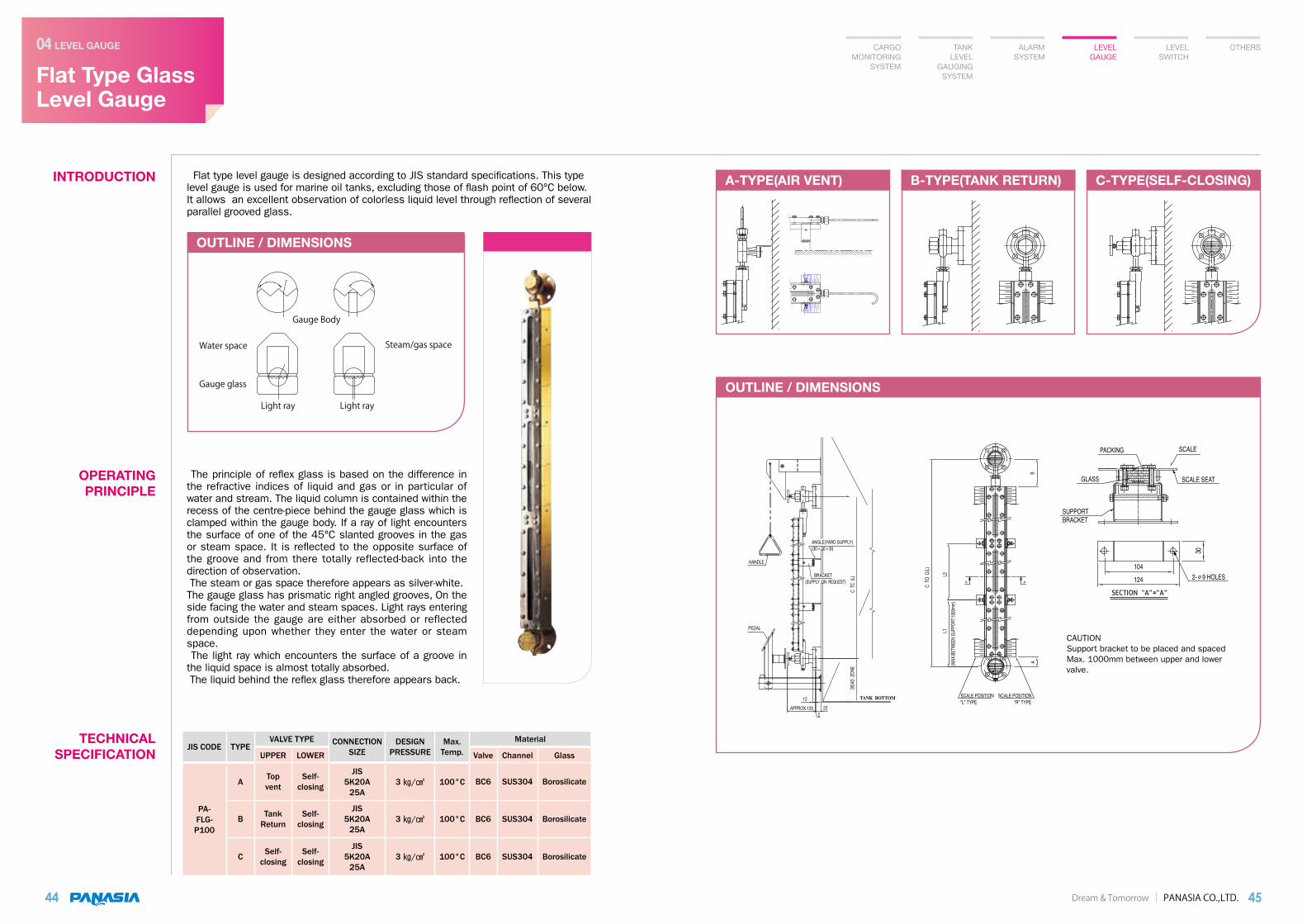
OUTLINE / DIMENSIONS
A-TYPE(AIR VENT) B-TYPE(TANK RETURN) C-TYPE(SELF-CLOSING)
Flat Type GlassLevel Gauge
LEVEL GAUGE04
44
INTRODUCTION Flat type level gauge is designed according to JIS standard specifications. This type level gauge is used for marine oil tanks, excluding those of flash point of 60°C below. It allows an excellent observation of colorless liquid level through reflection of several parallel grooved glass.
OPERATING PRINCIPLE
TECHNICAL SPECIFICATION
Dream & Tomorrow PANASIA CO.,LTD. 45
CARGO MONITORING
SYSTEM
TANK LEVEL
GAUGING SYSTEM
ALARM SYSTEM
LEVEL GAUGE
LEVEL SWITCH
OTHERS
The principle of reflex glass is based on the difference in the refractive indices of liquid and gas or in particular of water and stream. The liquid column is contained within the recess of the centre-piece behind the gauge glass which is clamped within the gauge body. If a ray of light encounters the surface of one of the 45°C slanted grooves in the gas or steam space. It is reflected to the opposite surface of the groove and from there totally reflected-back into the direction of observation. The steam or gas space therefore appears as silver-white.The gauge glass has prismatic right angled grooves, On the side facing the water and steam spaces. Light rays entering from outside the gauge are either absorbed or reflected depending upon whether they enter the water or steam space. The light ray which encounters the surface of a groove in the liquid space is almost totally absorbed. The liquid behind the reflex glass therefore appears back.
JIS CODE TYPEVALVE TYPE CONNECTION
SIZEDESIGN
PRESSUREMax.
Temp.Material
UPPER LOWER Valve Channel Glass
PA-FLG-P100
ATopvent
Self-closing
JIS5K20A
25A3 / 100°C BC6 SUS304 Borosilicate
B TankReturn
Self-closing
JIS5K20A
25A3 / 100°C BC6 SUS304 Borosilicate
C Self-closing
Self-closing
JIS5K20A
25A3 / 100°C BC6 SUS304 Borosilicate
Gauge Body
Water space
Light ray Light ray
Steam/gas space
Gauge glass
CAUTIONSupport bracket to be placed and spaced Max. 1000mm between upper and lower valve.

OUTLINE / DIMENSIONSOUTLINE / DIMENSIONS
Magnetic Float TypeLevel Gauge
LEVEL GAUGE04
46
INTRODUCTION
FEATURES
The measuring pipe (chamber) is connected to the tank to form a float chamber that has the same level as the tank. A float with a built-in magnetic floats freely on the surface of the liquid and transmits its movement in the pipe, without physical contact, to an externally mounted indicating strip (indicator). The indication strip is placed on the outside of the pipe and consists of numerous magnetic flaps which are white on one side and red on the other, as the float passes the red/white flaps, the flaps are one after the other turned 180 around their own axis. The flaps change from white to red with rising level and from red to white with falling level. The magnetic level gauge is particular advantage wherever dangerous and toxic media calling for careful level monitoring.
- No harms to the environment. Safety guarantee.- No leakage to atmosphere- No maintenance costs- Easy to read- Suitable for pressure tank
TECHNICAL SPECIFICATION
Dream & Tomorrow PANASIA CO.,LTD. 47
OPERATING PRINCIPLE
SYMBOL MOUNTING TYPE
CONNECTION SIZE
MEASURING RANGE
WORKING DONDITION SPECIFIC
GRAVITYACCURACY MATERIAL
PRESS. TEMP. CHAMBER FLOAT ROTOR COLUMNN
PLG-65MS-ㅁ-ㅁ Side JIS 5K 25A Max.
5000mm5 / 200°C Over 0.8 ± 10m/m SUS 304 SUS304 Aluminum
CARGO MONITORING
SYSTEM
TANK LEVEL
GAUGING SYSTEM
ALARM SYSTEM
LEVEL GAUGE
LEVEL SWITCH
OTHERS

OUTLINE / DIMENSIONS
Self-PoweredContents Gauge
LEVEL GAUGE04
48
INTRODUCTION PCG-150 series tank contents gauge requires no external power source for operation. The instrument is completely automatic and provides continuous indication of tank contents without the aid of batteries or hand pumps. This gauge unit is simply composed of diaphragm, capillary tube and dial type indicator.
Generally applied to fresh water, Lub oil, Diesel oil, Heavy fuel oil, solvent gasoil and noncorrosive liquid.
The diaphragm is affected by the hydrostatic head medium column in tank, which apply pressure to the oil filled capillary. The pressure applied to capillary expands bourdon tube of indicator, so that the indicator displays the level corresponding to actual tank level.
TECHNICAL SPECIFICATION
Dream & Tomorrow PANASIA CO.,LTD. 49
Model: PCG-150 Series
OPERATING PRINCIPLE
APPLICATION
GAUGE SIZE Dial ø 150
MOUNTING TYPE side, submersible mounting
SCALE OF INDICATION Height(m) &volume ()
ACCURACY ± 1.5% of full scale
OPERATINGTEMPERATURE RANGE -20°C to + 100°C
ENCLOSURE Weather proof
OVERLOAD Min, 100% of full scale
LENGTH OF CAPILLARY TUBE
5 meters, 2 meters(standard), other(option)
CARGO MONITORING
SYSTEM
TANK LEVEL
GAUGING SYSTEM
ALARM SYSTEM
LEVEL GAUGE
LEVEL SWITCH
OTHERS

Dial Type FloatLevel Gauge
LEVEL GAUGE04
50
INTRODUCTION Dial type float level gauge consists of float, measuring steel wire and indicating unit as main components.
A float accurately follows liquid level variations in the vertical direction (horizontal movement of the float is well restricted by guide pipe). Vertical movement of the float is transmitted through a measuring wire to the indication unit, in which the measuring wire is wound around a tape pulley kept under constant torque by constant spring. The ver tical movement is converted into rotation of the tape pulley in this way. This rotation is transmitted through a gear system to an indicator pointer which reads the liquid level on a scale dial of indicating unit.
TECHNICAL SPECIFICATION
Dream & Tomorrow PANASIA CO.,LTD. 51
Model: PDG-150 Series
OPERATING PRINCIPLE
CARGO MONITORING
SYSTEM
TANK LEVEL
GAUGING SYSTEM
ALARM SYSTEM
LEVEL GAUGE
LEVEL SWITCH
OTHERS
TYPE MODEL MOUNTING TYPE MEASURING RANGE INDICATION SYSTEM
DIRECTCONNECTION
TYPE
PDG-150SC-T Top(with chamber) 0 ~ 5 m One-point
PDG-150SW-T Top(with guide wire) 0 ~ 5 m One-point
PDG-150SW-S Top(with guide wire) 0 ~ 5 m One-point
PDG-150SC-S Top(with chamber) 0 ~ 5 m One-point
MAGNETICCOUPLING
TYPE(INDIRECT TYPE)
PDG-150SI-T Top 0 ~ 5 m One-point
PDG-150SI-S Side 0 ~ 5 m One-point
SPECIFIC GRAVITY ACCURACYWORKING CONDITION MATERIAL
TEMP. PRESS. G/G HEAD TAPE FLOAT GUIDE PIPE
0.7 ~ 1.5 ± 15m/m 150°C 0.2 / AC MC / SUS SUS304 N/A
0.7 ~ 1.5 ± 15m/m 150°C 0.2 / AC MC / SUS SUS304 N/A
0.7 ~ 1.5 ± 15m/m 150°C 0.2 / AC MC / SUS SUS304 N/A
0.7 ~ 1.5 ± 15m/m 150°C 0.2 / AC MC / SUS SUS304 N/A
0.65 ~ 1.5 ± 15m/m 150°C 2 / AC MC / SUS SUS316 SUS316
0.65 ~ 1.5 ± 15m/m 150°C 2 / AC MC / SUS SUS316 SUS316
* PLEASE CONTACT OUR FACTORY IF OTHER CONDITIONS ARE REQUIRED.
OUTLINE / DIMENSIONS OUTLINE / DIMENSIONS OUTLINE / DIMENSIONS

LEVEL SWITCH

Dream & Tomorrow PANASIA CO.,LTD.
OUTLINE / DIMENSIONS
MODEL NUMBER CODE SYSTEM
Horizontal Mounted Float Type Level Switch
LEVEL SWITCH05
54
INTRODUCTION APPLICATION Magnetic float type level switches monitor and control liquid levels in open or closed tank.
Magnetic float type level switches are widely used for heavy fuel oil tanks, settling tanks, sludge tanks, sewage tanks, fresh water tanks, lub oil tanks, D.O tanks and others.
OPERATING PRINCIPLE
TECHNICAL SPECIFICATION
55
CARGO MONITORING
SYSTEM
TANK LEVEL
GAUGING SYSTEM
ALARM SYSTEM
LEVEL GAUGE
LEVEL SWITCH
OTHERS
A permanent magnet is part of a float which rises or falls with the changing liquid level. This magnetic repells another magnet located opposite in the switch housing. In this way it causes a snap action contact effect. A switch unit provides on-off contacts.
FEATURES - Easy maintenance- Safe operating conditions- Reliable- Fully sealed- Durable float
PM - 12 -
Option T : Test Device C : Cranked E : Explosion Proot S : Submersible D : Differential
H : Horizontal Mounting
CONTACT Electrical microswitch,Change contact, SPDT
SWITCH RATING 250V AC, 3A
LIQUID DENSITY Min. 0.7kg/d
SWITCH HYSTERESIS 20mm height at 0.9kg/dSpecific weight
AMBIENT TEMPERATURE -30 to +70˚C
MEDIUM TEMPERATURE -25 to +135˚C
RATED PRESSURE 3kg/ (standard)
INSTALLATION Horizontal
PROTECTION OF SWITCH HOUSING IP 56, IP 68 (option)
FLOAT MATERIAL SUS 316
FLANGE, HOUSING SS 400, ALDC 8

Dream & Tomorrow PANASIA CO.,LTD.
OUTLINE / DIMENSIONS
Vertical Mounted Float Type Level Switch
LEVEL SWITCH05
56
INTRODUCTION APPLICATION Magnetic float type level sw i tches mon i to r and control liquid levels in open or closed tank.
Magnetic float type level switches are widely used for heavy fuel oil tanks, settling tanks, sludge tanks, sewage tanks, fresh water tanks, lub oil tanks, D.O tanks and others.
OPERATING PRINCIPLE
TECHNICAL SPECIFICATION
57
A permanent magnet is part of a float which rises or falls with the changing liquid level. This magnetic repells another magnet located opposite in the switch housing. In this way it causes a snap action contact effect. A switch unit provides on-off contacts.
FEATURES - Easy maintenance- Safe operating conditions- Reliable- Fully sealed- Durable float
MODEL NUMBER CODE SYSTEM
PM - 12 -
Option T : Test Device C : Cranked E : Explosion Proot S : Submersible D : Differential
V : Vertical Mounting
CONTACT Electrical micro switch, change contact, SPDT
SWITCH RATING 250V AC, 3A
LIQUID DENSITY min. 0.7 /d
SWITCH HYSTERESIS 20 height at 0.9/dSpecific weight
AMBIENT TEMPERATURE -30 to + 70°C
MEDIUM TEMPERATURE -25 to + 100°C
RATED PRESSURE 3 / (standard)
INSTALLATION vertical
PROTECTION OF SWITCH HOUSING IP 56, IP 65 (option)
FLOAT MATERIAL SUS 316
FLANGE, HOUSING SS 400, ALDC 8
CARGO MONITORING
SYSTEM
TANK LEVEL
GAUGING SYSTEM
ALARM SYSTEM
LEVEL GAUGE
LEVEL SWITCH
OTHERS

Dream & Tomorrow PANASIA CO.,LTD.
OUTLINE / DIMENSIONS
OUTLINE / DIMENSIONS
Displacement Type Level Switch
LEVEL SWITCH05
58
INTRODUCTION Displacement type level switch consists of compression spring, displacer and switch unit in which micro switch and magnetic are assembled.
TECHNICAL SPECIFICATION
59
FEATURES - Easy maintenance- Durable float- Wide differential- Fully sealed- Unaffected by liquid agitation
CARGO MONITORING
SYSTEM
TANK LEVEL
GAUGING SYSTEM
ALARM SYSTEM
LEVEL GAUGE
LEVEL SWITCH
OTHERS
MODEL APPLICATIONMAX.
PRESS(/)
MAX.TEMP.(°C)
SETTINGACCURACY
()
MOUNTINGFLANGE
(STANDARD)Min.
Sp.Gr.CONNECTION
PM-90AT-1C High or low alarm / control 10 100°C ± 10
JIS5K 80A
5K 100A10K 80A
10K 100A
0.85 TopFlange
PM-90AT-2C High or low alarm / control 10 100°C ± 10 0.85 Top
Flange
PM-90AT-3C High or low alarm / control 10 100°C ± 10 0.85 Top
Flange
CABLEGLAND
SWITCHCONTACTRATING
MATERIAL MODES PM-90AT-1C PM-90AT-1C PM-90AT-1C
HOUSING FLANGE DISPLACER CHAMBER DIFFERENTIAL() *1
UPPER ;30 to 50
UPPER ; 30 to 50
UPPER ; 30 to 50
LOWER ; 30 to 50
LOWER ; 30 to 50
LOWER ; 200 to 4500
15/20a,b,c
250VAC5A
ALDCSS400
orSUS304
SUS 30476.8Ø100L
SS400or
SUS304
Contactconfiguration
15/20a,b,c
250VAC,
5A X 2ALDC
SS400or
SUS304
SUS 30476.8Ø100L
SS400or
SUS304
15/20a,b,c
250VAC,
5A X 2ALDC
SS400or
SUS304
SUS 30476.8Ø100L
SS400or
SUS304
(OPERATING SIGNAL)
(VIEW “A”)
(OPERATING SIGNAL)(VIEW “A”)
(OPERATING SIGNAL)
(VIEW “A”)
(OPERATING SIGNAL)
(VIEW “A”)
(OPERATING SIGNAL)(VIEW “A”)
(OPERATING SIGNAL)
(VIEW “A”)
(OPERATING SIGNAL)
(VIEW “A”)
(OPERATING SIGNAL)(VIEW “A”)
(OPERATING SIGNAL)
(VIEW “A”)
PM-90AT-1C PM-90AT-2C
PM-90AT-3C
Dream & Tomorrow PANASIA CO.,LTD.
OUTLINE / DIMENSIONS
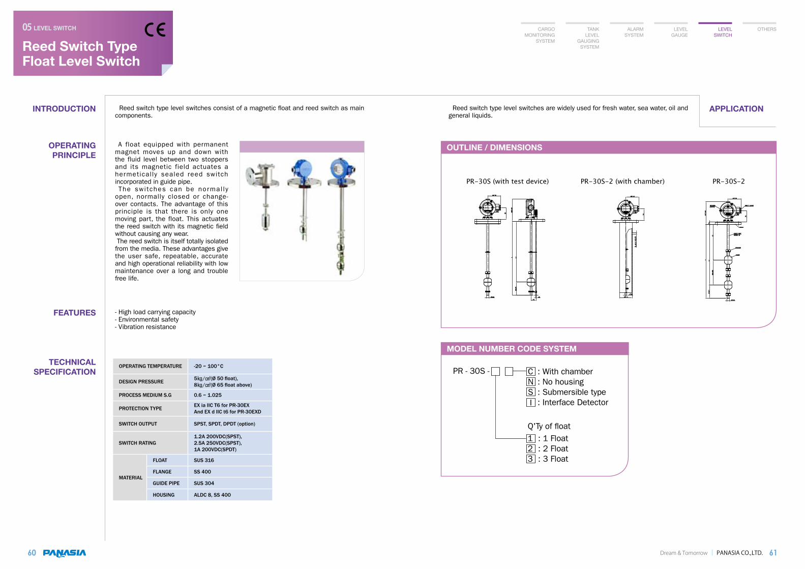
Reed Switch Type Float Level Switch
LEVEL SWITCH05
60
INTRODUCTION APPLICATION Reed switch type level switches consist of a magnetic float and reed switch as main components.
Reed switch type level switches are widely used for fresh water, sea water, oil and general liquids.
OPERATING PRINCIPLE
TECHNICAL SPECIFICATION
61
A float equipped with permanent magnet moves up and down with the fluid level between two stoppers and its magnetic field actuates a hermetically sealed reed switch incorporated in guide pipe. The switches can be normal ly open, normally closed or change-over contacts. The advantage of this principle is that there is only one moving part, the float. This actuates the reed switch with its magnetic field without causing any wear. The reed switch is itself totally isolated from the media. These advantages give the user safe, repeatable, accurate and high operational reliability with low maintenance over a long and trouble free life.
FEATURES - High load carrying capacity- Environmental safety- Vibration resistance
CARGO MONITORING
SYSTEM
TANK LEVEL
GAUGING SYSTEM
ALARM SYSTEM
LEVEL GAUGE
LEVEL SWITCH
OTHERS
OPERATING TEMPERATURE -20 ~ 100°C
DESIGN PRESSURE 5/(Ø 50 float),8/(Ø 65 float above)
PROCESS MEDIUM S.G 0.6 ~ 1.025
PROTECTION TYPE EX ia IIC T6 for PR-30EXAnd EX d IIC t6 for PR-30EXD
SWITCH OUTPUT SPST, SPDT, DPDT (option)
SWITCH RATING1.2A 200VDC(SPST),2.5A 250VDC(SPST),1A 200VDC(SPDT)
MATERIAL
FLOAT SUS 316
FLANGE SS 400
GUIDE PIPE SUS 304
HOUSING ALDC 8, SS 400
MODEL NUMBER CODE SYSTEM
PR - 30S -
Q'Ty of float1 : 1 Float2 : 2 Float3 : 3 Float
C : With chamber N : No housing S : Submersible type : Interface DetectorI

OTHERS

Dream & Tomorrow PANASIA CO.,LTD.
INDICATOR
OTHERS06
64
1. ELECTRIC INDICATOR
3. ALARM & DISPLAY MONITOR
2. BARGRAPH TYPE
INDICATOR
65
CARGO MONITORING
& CONTROL SYSTEM
TANK LEVEL
GAUGING SYSTEM
ALARM SYSTEM
LEVEL GAUGE
LEVEL SWITCH
OTHERS
PAI-100A
PAI-4000
MODEL PAI-100A
SIZE 110×110 Square
MOUNTING METHOD Panel front mounting
INPUT DC 4~20mA
INTERNAL RESISTANCE 1.5 Ω
ACCURACY ± 1.5% F.SAT 20°C
MEASURING RANGE 0~100%(Standard)
INDICATING ANGLE 250deg
WEIGHT 450g
OPERATING TEMPERATURE 0 to + 40°C
COLOR Black
APPLICATION Panel, local gauge box and console
MODEL PA 1300
INPUT POWER 24 Vdc reverse polarity protected ripple
INPUT CHNNEL 8 channel
INPUT SIGNAL 4 – 20 mA, 2 wire
ACCURACY ≤ ± 0.1 % of F.S
LINEARITY ERROR ≤± 0.05 % of F.S
TEMPERATURE INFLUENCE ≤± 0.01 % on zero and span for a 1˚C change
ALARM DELAY 0 – 99 sec. (Maker standard : 0 sec.)
LCD 20 Cha. X 4 Lines (Backlight type)
OPERATING TEMPERATURE - 20 … + 60 ˚C
STORAGE TEMPERATURE - 25 … + 75 ˚C
PROTECTION CLASS IP 22
WEIGHT 400 g
PA 1300
MODEL PAI-4000
ACCURACY 0.1% of F.S
SCALE Display dual mode.(level & volume)
HEIGHT Display(M/M )
VOLUME Max. 16 Gradient %Display
INPUT A) DC 4~20mA(1-5V) or variable resistanceB) RS-485
DIGIT 4 Digit
OUTPUT Alarm contact, RS485
ALARM POINT 2point, 4point (option)
HH Dry contact notmal open or close (option)
H Dry contact notmal open or close
L Dry contact notmal open or close
LL Dry contact notmal open or close (option)
MATERIAL ABS
POWER DC24V, 6W(MAX.)
TEMPERATURE 0°C~50°C
WEIGHT 1.0Kg
3

CLASS APPROVALS
66
Global Leader In Smart & Green TechnologyWith Technology! For the world! Toward the Future!
CLASSIFICATION SOCIETY
PRODUCTS
CLASS
KR ABS BV DNV LRS NK GL RINA CCS
RADAR BEAM TYPE CARGO MONITORING SYSTEM O O O O O O O O O
MAGNETIC FLOAT TYPE CARGO MONITORING SYSTEM O O O O O O O O O
HIGH LEVEL ALARM SYSTEM O O O O O O O O O
AIR PURGE TYPE & ELECTRIC PNEUMATIC TYPE LEVEL GAUGING SYSTEM
O O O O O O O O O
ELECTRIC PRESSURE TYPELEVEL TRANSMITTER O O O O O O O O O
WATER INGRESS ALARM SYSTEM O O O O O O O O O
LEVEL GAUGE - SELF POWER CONTENT GAUGE - FLAT TYPE GLASS LEVEL GAUGE - MAGNETIC FLOAT TYPE LEVEL GAUGE
O O O O O O O O
LEVEL SWITCH - PM -12 SERIES - PM-90 SERIES - PR-30 SERIES
O O O O O O O O
WORLD WIDESERVICE NETWORK
Dream & Tomorrow PANASIA CO.,LTD. 67
Global Leader In Smart & Green TechnologyWith Technology! For the world! Toward the Future!
1. California, U.S.A2. Maiquetia, VENEZUELA3. Rio de janeiro, BRAZIL4. New Brunswick, CANADA
1. Rotterdam, THE NETHERLANDS2. Split, CROATIA3. Opatija, CROATIA4. Limassol, CYPRUS5. Tallinn, ESTONIA6. Paris, FRANCE7. Hamburg, GERMANY8. Piraeus, GREECE9. La Spezia, ITALY10. Oslo, NORWAY11. Galati, ROMANIA12. Istanbul, TURKEY
1. Busan, KOREA2. Shanghai, CHINA3. Guangzhou, CHINA4. Osaka, JAPAN5. Fukuyama, JAPAN6. Kobe, JAPAN7. Oita, JAPAN8. Hong Kong9. Mumbai, INDIA10. Jakarta, INDONESIA11. Kuala Lumpur, MALAYSIA12. Vladivostock, RUSSIA13. SINGAPORE14. TAIWAN
AMERICA
MIDDLE EAST
EUROPE
ASIA
1. Dubai, U.A.E
AFRICA1. Lagos, NIGERIA

Catalog No. MEASUREMENT & CONTROL V11.2
PANASIA GUANGZHOU BRANCH Rm 837, Weini (Vili) International Building, No.167, Linhe West Rd, Tianhe District, Guangzhou City, China TEL: +86-20-3877-8861 MOB: +86-186-8025-4636E-mail: [email protected]
PANASIA JAPAN CORPORATIONSakaisuji Honmachi Center Bill 16F, 2-1-6, Honmachi, Chuo-ku, Osaka, Japan TEL: +81-6-6261-3400~1 FAX: +81-6-6261-3402E-mail: [email protected]
PANASIA EUROPE BRANCH Speedwellstraat 11, 3029BL, Rotterdam, The Netherlands TEL: +31-10-226-1878 MOB: +31-6-3913-0664E-mail: [email protected]
FACTORY IN GIMHAE
PANASIA CHINA CORPORATION IN SHANGHAI
HEAD OFFICE & FACTORY 1559-3, Songjeong-Dong, Gangseo-Gu, Busan, Korea TEL: +82-51-831-1010FAX: +82-51-831-1399http: //www.worldpanasia.comE-mail: [email protected]
SALES CENTER TEL: +82-51-970-1513E-mail: [email protected]
R&D CENTER TEL: +82-51-970-1537E-mail: [email protected]
DESIGN CENTER TEL: +82-51-970-1526E-mail: [email protected]
SERVICE CENTER TEL: +82-51-970-1545E-mail: [email protected]
HEAD OFFICE IN BUSAN
FACTORY / E&C DIVISION 715-1, Yongduk-Ri, Hanlim-Myun, Gimhae, Gyeongnam, Korea TEL: +82-55-310-3300, FAX: +82-55-343-3318E-mail: [email protected]
PANASIA CHINA CORPORATIONRm C-205, No.2080-50, Lianhua Rd, Shanghai, China TEL: +86-21-6235-1601~3FAX: +86-21-6401-9918E-mail: [email protected]
C&C PANASIA INC. 2975 Treat Blvd. Suite A-5, Concord, CA 94518 Toll Free: +1-888-90-PANOX TEL: +1-925-265-1003~4, FAX: +1-925-265-1014E-mail: [email protected]&C PANASIA IN CALIFORNIA
PANASIA JAPAN CORPORATION