Measurement and stability of the pointing of the BepiColombo Laser Altimeter under thermal load
10
Measurement and stability of the pointing of the BepiColombo Laser Altimeter under thermal load Julien Gouman a,n , Thomas Beck a , Michael Affolter b , Nicolas Thomas a , Urs Geissbühler a , Alain Péteut a , Timothy Bandy a , Anthony Servonet a , Daniele Piazza a , Karsten Seiferlin a , Kaustav Ghose a a Physikalisches Institut, Universität Bern, Sidlerstrasse 5, 3012 Bern, Switzerland b Paul Scherrer Institute, 5232 Villigen, Switzerland article info Article history: Received 28 May 2014 Received in revised form 2 September 2014 Accepted 8 September 2014 Available online 16 September 2014 Keywords: BepiColombo Laser altimeter BELA Thermal vacuum Stability abstract The BepiColombo Laser Altimeter (BELA) has been selected to fly on ESA's BepiColombo mission to Mercury. The instrument will be the first European laser altimeter designed for interplanetary flight. This paper describes the setup used to characterize the angular movements of BELA under the simulated environmental conditions that the instrument will encounter when orbiting Mercury. The system comprises a laser transmitter and a receiving telescope, which can move with respect to each other under thermal load. Tests performed using the Engineering Qualification Model show that the setup is accurate enough to characterize angular movements of the instrument components to an accuracy of E10 μrad. The qualification instrument is thermally stable to operate during all mission phases around Mercury proving that the transmitter and receiver sections will remain within the alignment requirements during its mission. & 2014 IAA. Published by Elsevier Ltd. All rights reserved. 1. Introduction BepiColombo is the first European Space Agency (ESA) mission to the planet Mercury and has been developed in collaboration with the Japan Aerospace eXploration Agency (JAXA). It consists of two spacecraft: the MPO (Mercury Planetary Orbiter) built by ESA and the MMO (Mercury Magnetospheric Orbiter) built by JAXA. The mission will investigate the origin and the evolution of Mercury, its exosphere, its magnetosphere, the origin of its magnetic field and will test Einstein's theory of general relativity [1]. The biggest instrument on the MPO is BELA (the Bepi Colombo Laser Altimeter) which is designed to measure the topography of Mercury and to place constraints on Mercury's interior structure by measuring the time-of-flight of a laser pulse emitted from the instrument and reflected back from the surface of the planet. The MPO will be nominally in a 400 km 1508 km orbit about Mercury with an orbital period of 2.3 h [2]. The prime mission is intended to last 1 Earth year. 1.1. Laser altimetry The use of laser altimetry for planetary science began with Apollo 15 where it was used to measure the distance between the lander and the surface of the Moon during the descent. Instruments have subsequently been used to characterize the surfaces of the Moon (LOLA: Lunar Orbiter Laser Altimeter [3]), the Earth (GLAS: the Geoscience Laser Contents lists available at ScienceDirect journal homepage: www.elsevier.com/locate/actaastro Acta Astronautica http://dx.doi.org/10.1016/j.actaastro.2014.09.006 0094-5765/& 2014 IAA. Published by Elsevier Ltd. All rights reserved. n Corresponding author. Physics Institute, Space Research and Planetary Sciences, Sidlerstrasse 5, CH- 3012 Bern, Switzerland. Tel.: þ41 316313335. E-mail address: [email protected] (J. Gouman). Acta Astronautica 105 (2014) 171–180
Transcript of Measurement and stability of the pointing of the BepiColombo Laser Altimeter under thermal load

Contents lists available at ScienceDirect
Acta Astronautica
Acta Astronautica 105 (2014) 171–180
http://d0094-57
n CorrScience3163133
E-m
journal homepage: www.elsevier.com/locate/actaastro
Measurement and stability of the pointing of the BepiColomboLaser Altimeter under thermal load
Julien Gouman a,n, Thomas Beck a, Michael Affolter b, Nicolas Thomas a,Urs Geissbühler a, Alain Péteut a, Timothy Bandy a, Anthony Servonet a,Daniele Piazza a, Karsten Seiferlin a, Kaustav Ghose a
a Physikalisches Institut, Universität Bern, Sidlerstrasse 5, 3012 Bern, Switzerlandb Paul Scherrer Institute, 5232 Villigen, Switzerland
a r t i c l e i n f o
Article history:Received 28 May 2014Received in revised form2 September 2014Accepted 8 September 2014Available online 16 September 2014
Keywords:BepiColomboLaser altimeterBELAThermal vacuumStability
x.doi.org/10.1016/j.actaastro.2014.09.00665/& 2014 IAA. Published by Elsevier Ltd. A
esponding author. Physics Institute, Space Res, Sidlerstrasse 5, CH- 3012 Bern, Swit35.ail address: [email protected] (J
a b s t r a c t
The BepiColombo Laser Altimeter (BELA) has been selected to fly on ESA's BepiColombomission to Mercury. The instrument will be the first European laser altimeter designed forinterplanetary flight. This paper describes the setup used to characterize the angularmovements of BELA under the simulated environmental conditions that the instrumentwill encounter when orbiting Mercury. The system comprises a laser transmitter and areceiving telescope, which can move with respect to each other under thermal load. Testsperformed using the Engineering Qualification Model show that the setup is accurateenough to characterize angular movements of the instrument components to an accuracyof E10 μrad. The qualification instrument is thermally stable to operate during allmission phases around Mercury proving that the transmitter and receiver sections willremain within the alignment requirements during its mission.
& 2014 IAA. Published by Elsevier Ltd. All rights reserved.
1. Introduction
BepiColombo is the first European Space Agency (ESA)mission to the planet Mercury and has been developed incollaboration with the Japan Aerospace eXploration Agency(JAXA). It consists of two spacecraft: the MPO (MercuryPlanetary Orbiter) built by ESA and the MMO (MercuryMagnetospheric Orbiter) built by JAXA. The mission willinvestigate the origin and the evolution of Mercury, itsexosphere, its magnetosphere, the origin of its magneticfield and will test Einstein's theory of general relativity [1].
ll rights reserved.
search and Planetaryzerland. Tel.: þ41
. Gouman).
The biggest instrument on the MPO is BELA (the BepiColombo Laser Altimeter) which is designed to measure thetopography of Mercury and to place constraints on Mercury'sinterior structure by measuring the time-of-flight of a laserpulse emitted from the instrument and reflected back fromthe surface of the planet. The MPO will be nominally in a400 km�1508 km orbit about Mercury with an orbital periodof 2.3 h [2]. The prime mission is intended to last 1 Earth year.
1.1. Laser altimetry
The use of laser altimetry for planetary science beganwith Apollo 15 where it was used to measure the distancebetween the lander and the surface of the Moon during thedescent. Instruments have subsequently been used tocharacterize the surfaces of the Moon (LOLA: Lunar OrbiterLaser Altimeter [3]), the Earth (GLAS: the Geoscience Laser

Fig. 1. CAD model of the BELA instrument.
J. Gouman et al. / Acta Astronautica 105 (2014) 171–180172
Altimeter System [4]), Mars (MOLA: Mars Orbiter LaserAltimeter [5]) and the northern hemisphere of Mercury.The laser altimeter (MLA: Messenger Laser Altimeter)onboard the MESSENGER spacecraft [6] has been returningdata from Mercury since 2011.
The principle behind laser altimetry is relatively simple.A laser transmitter (Tx) emits a laser pulse which isreflected by the planetary surface and the return pulse isthen collected by a receiver. The time-of-flight,Δt, betweenthe emission of the pulse and its return to the receiver (Rx)is measured. The distance, h, between the instrument andthe surface of the planet is then calculated by
h¼ 12 cΔt; ð1Þ
where c¼299,792,458 m/s [7].All interplanetary laser altimeters to date have used the
“classical” approach to instrument design. Here, a highenergy pulse (20–50 mJ) with a pulse duration of the orderof 5 ns is emitted from the instrument at a repetition rateof typically 1–10 Hz. Return pulse strengths of the order of100 photons are then detected by the receiver. The alter-native approach, single photon counting [8], which hasadvantages in terms of power consumption, accuracy andcoverage, has yet to be implemented on a mission for costand complexity reasons. However, even with the classicaltechnique, if the exact position of the spacecraft is known,the distance to the surface can be determined with avertical resolution in the submeter range [9]. In addition,the shape and the amplitude of the return pulse can beanalyzed to provide information on the roughness, theslope, and the reflectivity of the surface [5].
To maximize the precision of these measurementsparticularly on the dayside of the target, the receiver fieldof view must be as small as possible to limit the back-ground from reflected sunlight (which increases withdetector field of view). The laser spot, however, has to bemaintained within this field of view. Requirements on theaccuracy of the alignment and the stability of the align-ment have to be set and guaranteed over the range ofenvironmental conditions to be experienced by theinstrument.
Flight instruments developed for space have to with-stand large changes in environmental conditions. TheBELA instrument is no exception. The thermal environ-ment around Mercury is of particular concern. The perfor-mance of LOLA on NASA's Lunar Reconnaissance Orbiter,the latest laser altimeter to provide a high global resolu-tion topographic map of the Moon and in operation since2009, illustrates a significant potential problem. LOLA hasfive channels in the focal plane providing a swath ofmeasurements. When LRO is above the night side of theMoon, the instrument cools down and loses the signal insome of the channels (more than 50% of the data over thenight side). Investigation has established that this iscaused by the alignment of the transmitter and thereceiver being affected by changes in the thermal load onthe system. The relative displacement between the lines ofsight of the transmitter and the receiver is significant(E600 μrad), and the laser spot moves out of the fieldof view of the receiver [10]. Given the more extremethermal conditions at Mercury, the BELA team considered
it mandatory to validate that the instrument design couldmaintain its alignment over the full range of thermal loads.
1.2. BELA
BELA is a joint project of the University of Bern (Switzer-land) and DLR (Deutsches Zentrum für Luft- und Raumfahrte.V) Berlin (Germany) with contributions from the MaxPlanck Institute for Solar System Research (MPS) and theAndalucian Astrophysics Institute (IAA). BELA consists oftwo subsystems: the transmitter (designed in Germany)and the receiver (designed in Switzerland) (Fig. 1).
The transmitter and the receiver are mounted on acommon baseplate. The baseplate has an (almost) 0 CTE(Coefficient of Thermal Expansion) in order to limit thedisplacements of the transmitter/receiver over the tem-perature range of the instrument. Although translations ofthe sub-systems with respect to each other are insignif-icant for measurements, small angular displacements canhave major consequences.
The transmitter part comprises a 50mJ (at beginning oflife) Nd:YAG laser (built by Cassidian Optronics) emitting apulse repetition frequency of 10 Hz at 1064.6 nm (at 25 1C). Inorder to keep the laser spot small on the surface, a beamexpander (BEX) is placed in front of the laser to collimate thebeam and produce a divergence of 60 μrad (full width halfmaximum) corresponding to a footprint of 24m on the surfacefrom 400 km above the surface of the planet. The pulserepetition frequency leads to a horizontal spacing of 250m.
A Straylight Protection Unit is located after the beamexpander to protect the laser head box and the front lens ofthe BEX from contamination. The high power of the lasercan vaporize dust particles on surfaces, leading to highlyreactive by-products and subsequent coating damage.
On the receiver, the reflected beam is collected by a200 mm Ritchey-Chrétien Cassegrain telescope (a focallength of 1250 mm and a designed field of view of450 μrad) built by RUAG Space AG using beryllium toproduce a light weight, strong structure. The receivedlaser pulse is detected by a Excelitas (former Perkin-Elmer)Avalanche Photo Diode (APD) with a 0.8 mm diameter(C30954E). This APD was selected because of its highinfrared quantum efficiency and sensitivity at low lightlevels with low dark noise. Between the telescope and the

J. Gouman et al. / Acta Astronautica 105 (2014) 171–180 173
detector, the Back-End-Optics collects the focused beam ofthe return pulse from the planet and makes it parallel.A filter inside the Back-End-Optics transmits wavelengthsin the range of 1064.387 0.89 nm and the beam is thenrefocused onto the detector.
To protect the instrument from solar straylight, baffles arelocated in front of the transmitter (Transmitter Baffle Unit)and in front of the receiver (Receiver Baffle Unit) (Fig. 1). Anysolar ray entering these baffles with an angle between 381and 901 from the boresight will be rejected in only 1.2reflections on average [11]. Additionally, the TBU contains afilter to reject the solar light reflected by the surface ofMercury. This filter is needed to limit the light coming fromMercury entering the laser through the BEX. The BEX couldfocus this light into the laser which can lead to damage. Theelectronics unit provides, for each pulse, the time-of-flight ofthe laser pulse, its return width and amplitude.
In order to produce a high resolution global topo-graphic map of Mercury, the BELA instrument will benominally nadir pointing. A Sun shield approach waschosen for the MESSENGER spacecraft to solve the space-craft thermal problems at Mercury [12], resulting in moremoderate temperatures than for MPO. The BepiColomboMPO has been designed as a nadir pointing spacecraft;hence the temperature range on the BELA instrument willbe significantly larger.
Current models suggest that inside the BepiColombospacecraft, the temperatures of most of the instruments willbe kept within a temperature range of 0–40 1C. However,for specific instruments, interface temperatures can bebelow and above this range [2]. BELA has an operationaltemperature range between �33 1C and 58 1C with theexternal baffles reaching a maximum of 140 1C when theSun shines into the reflective baffle of the instrument. Thelarge temperature range is partially a consequence of theeccentricity of Mercury's orbit about the Sun.
The development of the transmitter and the receiver intwo different countries has necessitated clean interfacedefinitions and considerable planning with respect tomounting and co-alignment. The alignment budget islisted in Table 1. Misalignment between the transmitterand the receiver can arise from several different factorswhich are summarized in Table 1. Items A and B comefrom the co-alignment of the instrument and its measure-ment accuracy when the laser is mounted onto the base-plate. Misalignment can also arise from thermal andmechanical movement of the transmitter, receiver, andmounting baseplate (items C, D and E in Table 1). The laserdivergence (Table 1 item G) must also be taken intoaccount. The image produced by the telescope is blurredby optical imperfections and this is accounted for in itemH. The last item (item I) is the result of the travel time ofthe laser beam to and from the surface combined with thespacecraft motion. One might expect that this misalign-ment could be pre-compensated. However, for thermalreasons, the spacecraft must flip every half Mercury year.The total misalignment must be lower than 225 μrad toensure that the BELA laser spot stays in the field of view ofthe receiver during BELA orbital operations (Table 1).
An important point to verify during testing is thebehavior of the angular movements which could occur
during 1 year operation in orbit around Mercury [13]. Twosetups have been designed at the University of Bern: one toprovide an accurate measurement of the alignment of theBELA instrument [14], and the other to verify that theinstrument will remain aligned under varying thermal load.
The receiver telescope is accepted from Swiss industryalready complete and mounted to the baseplate. Thismeans that the back-end-optics and detector are alreadymounted and aligned to form the complete receiver chain.The 1064 nm filter in the receiver chain and the relativelylarge single pixel detector in the focal plane complicatesthe determination of the optical line of sight. To overcomethese difficulties, the back of the secondary mirror isequipped with a flat mirror reflector and can thereforebe used as a reference (Fig. 2).
The receiver line of sight is not necessarily perpendi-cular to the back of the secondary mirror. It was thereforerequested that the receiver line of sight be measured withrespect to the back of the secondary mirror by themanufacturer. For the engineering qualification unit, theangle between the line of sight and the vector orthogonalto the back of the secondary mirror was 268 μrad.
The BELA instrument requires an accurate initial align-ment (o60 μrad, Table 1, item A). The current capabilityof the co-alignment setup results in an accuracy ofapproximately 23 μrad which leaves some margin to therequired value of 50 μrad (Table 1, item B) [14]. Thetransmitter and the receiver have to remain aligned toeach other with this result as an initial starting condition.The setup for stability tests of BELA under thermal vacuumconditions has to prove that the laser is stable with respectto the telescope line of sight and show an angularmisalignment within specification.
This paper describes the concept of the setup, designedand calibrated at the University of Bern, to demonstratethe ability of BELA to operate in a thermal vacuumenvironment that simulates the worst case conditions thatcould be encountered during all the phases of the mission.It also presents the results of these tests on the Engineer-ing Qualification Model (EQM). First of all, we describe inSection 2 the setup designed to measure the angularmovements of the instrument during the simulation ofthe environmental conditions around Mercury. Next, wedescribe in Section 3, the procedure to adjust the setup tothe instrument. Finally we describe and discuss in Sections4 and 5 the results we obtained during the test with theEQM of BELA instrument and the improvements which canbe made to this setup for the future.
2. Setup for stability tests of BELA under thermal vacuumconditions
Fig. 3 shows the configuration of the test setup. On theright side, the BELA instrument is seen mounted inside thethermal vacuum chamber. On the left side, a light-tight boxcontains the optical setup to detect the angular movementsof each part of BELA (BELA's laser, receiver telescope andthe optical cube mounted on the baseplate, Fig. 1).
The optical setup is divided into three sections to makeseparate but related measurements. The three sections
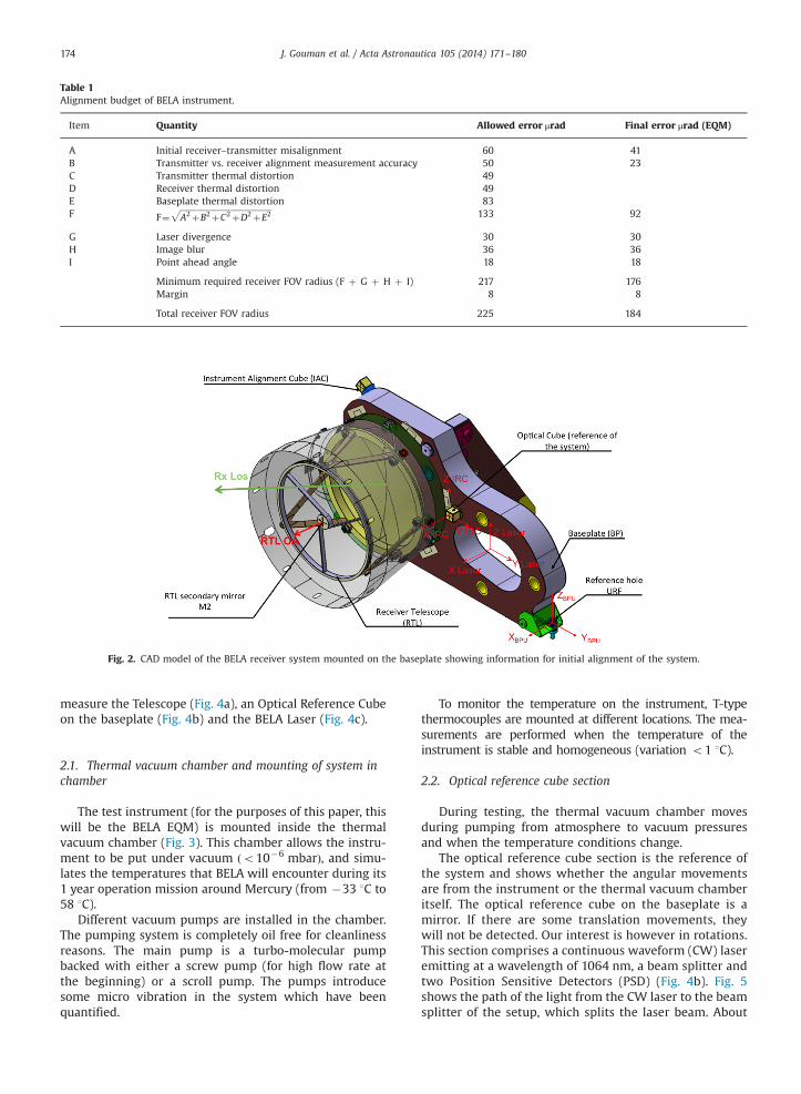
Table 1Alignment budget of BELA instrument.
Item Quantity Allowed error μrad Final error μrad (EQM)
A Initial receiver–transmitter misalignment 60 41B Transmitter vs. receiver alignment measurement accuracy 50 23C Transmitter thermal distortion 49D Receiver thermal distortion 49E Baseplate thermal distortion 83F F¼
ffiffiffiffiffiffiffiffiffiffiffiffiffiffiffiffiffiffiffiffiffiffiffiffiffiffiffiffiffiffiffiffiffiffiffiffiffiffiffiffiffiffiffiffiffiA2þB2þC2þD2þE2
p133 92
G Laser divergence 30 30H Image blur 36 36I Point ahead angle 18 18
Minimum required receiver FOV radius (F þ G þ H þ I) 217 176Margin 8 8
Total receiver FOV radius 225 184
Fig. 2. CAD model of the BELA receiver system mounted on the baseplate showing information for initial alignment of the system.
J. Gouman et al. / Acta Astronautica 105 (2014) 171–180174
measure the Telescope (Fig. 4a), an Optical Reference Cubeon the baseplate (Fig. 4b) and the BELA Laser (Fig. 4c).
2.1. Thermal vacuum chamber and mounting of system inchamber
The test instrument (for the purposes of this paper, thiswill be the BELA EQM) is mounted inside the thermalvacuum chamber (Fig. 3). This chamber allows the instru-ment to be put under vacuum ðo10�6 mbarÞ, and simu-lates the temperatures that BELA will encounter during its1 year operation mission around Mercury (from �33 1C to58 1C).
Different vacuum pumps are installed in the chamber.The pumping system is completely oil free for cleanlinessreasons. The main pump is a turbo-molecular pumpbacked with either a screw pump (for high flow rate atthe beginning) or a scroll pump. The pumps introducesome micro vibration in the system which have beenquantified.
To monitor the temperature on the instrument, T-typethermocouples are mounted at different locations. The mea-surements are performed when the temperature of theinstrument is stable and homogeneous (variation o1 1C).
2.2. Optical reference cube section
During testing, the thermal vacuum chamber movesduring pumping from atmosphere to vacuum pressuresand when the temperature conditions change.
The optical reference cube section is the reference ofthe system and shows whether the angular movementsare from the instrument or the thermal vacuum chamberitself. The optical reference cube on the baseplate is amirror. If there are some translation movements, theywill not be detected. Our interest is however in rotations.This section comprises a continuous waveform (CW) laseremitting at a wavelength of 1064 nm, a beam splitter andtwo Position Sensitive Detectors (PSD) (Fig. 4b). Fig. 5shows the path of the light from the CW laser to the beamsplitter of the setup, which splits the laser beam. About

Fig. 3. CAD model of the stability test setup under thermal vacuum conditions.
Fig. 4. Setup for stability tests of BELA under thermal vacuum conditions.
J. Gouman et al. / Acta Astronautica 105 (2014) 171–180 175
50% of the light goes to the PSD1 (Fig. 4b); the other 50%goes through the window and illuminates the opticalcube (mounted on the baseplate). From here, thereflected light goes back to PSD2.
When the CW laser is switched on, the inside of the laserheats and the beammaymove. This illustrates why two PSDsare used (Fig. 4b): one PSD measures the movement of theCW laser itself (PSD1) and the other measures the movementof the CW laser and checks if the optical reference cubeundergoes an angular displacement as a result of deforma-tion of the baseplate (PSD2). Subtracting PSD1 from PSD2
(Fig. 4) provides the angular movement of the optical cube.
The deviation of the optical reference cube is calculatedusing the following equation:
Δα¼arctan
ΔdD
� �
4; ð2Þ
where
�
Δd is the displacement of the beam on the PSD fromone measurement to another (Δd¼ PSD2�PSD1). � D is the nominal distance between the optical referencecube and the PSD
Fig. 5. Optical cube section (left: optical path from the CW laser to the window; right: optical path from the window to the optical cube).
Fig. 6. BELA laser part (left: optical path from the BELA laser to the window; right: optical path from the window to the beam reducer).
J. Gouman et al. / Acta Astronautica 105 (2014) 171–180176
These angular movements from the reference system,during a thermal vacuum test, can be known with anaccuracy of E5 μrad.
The factor of 4 arises from the beam changing itsposition on the beam splitter. Due to the 451 mirror withinthe beam splitter, the angular deviation on the detector isdoubled. The factor takes this into account.
2.3. BELA laser section
This part of the setup analyzes the angular movementsof the BELA laser which occur during the thermalvacuum test.
It contains a set of filters, a beam reducer, a beamsplitter, a lens and two CCD (charge-coupled devices)cameras (Fig. 4c). Since the BELA laser is a 50 mJ pulsedsystem with a pulse power of over 10 MW, it could easilydamage the CCDs during the tests. An attenuator is needed(labelled “filter 1” in Fig. 6). The beam reducer then reducesthe 75 mm beam diameter by a 10:1 factor. The beamreducer multiplies the angular movements coming from theBELA laser by a factor of about 10 (BRF – Beam ReducerFactor). Thus it enables a detection of smaller angles.
Next, there is the beam splitter. About 50% of the laserbeam goes to CCD-1 which gives an overview of the beamshape and monitors the beam profile stability. The other
50% goes to CCD-2. This detector measures only angularmovements as the mounted lens in front removes thetranslation movements. The lens allows focusing always toone point and if there are translational movements, thedetector does not detect them.
Tests have shown that this part is able to detect an angulardisplacement during the thermal vacuum test of roughly10 μrad. Since there is only one detector for the angularmovement measurements (CCD-2) (and not two as the opticalcube part of the setup), the error on this part is larger.
The angular displacement in this case can be calculatedusing the following equation:
Δα¼arctan Δd
f
� �BRF � 2
; ð3Þ
where
�
Δd is the displacement of the beam on the CCD-2 fromone measurement to another.�
f is the focal length of the lens. � BRF (beam reducer factor) is the factor arising from thebeam reducer.
It has been mentioned earlier that the beam reducermultiplies the angular movements coming from the BELA

Fig. 7. Schematic of the setup used to characterize the Beam ReducerFactor (BRF). Fig. 8. 451 mirror system from the telescope section.
J. Gouman et al. / Acta Astronautica 105 (2014) 171–180 177
laser by a factor of roughly 10. This beam reducer factor hasto be taken into account in Eq. (3). It has been characterizedbefore the thermal vacuum test using a mirror controlled ontwo axes (horizontal and vertical axis) by picomotors. Thetilt of the mirror (α) is measured by an autocollimator withan accuracy of 1 μrad (Fig. 7)
x¼ tan ðαÞ � f � BRF; ð4Þwhere
�
x is the displacement on the detector (mm). � f is the focal length of the lens. � α is the tilt of the picomotors on the mirror.Fig. 9. Scan of the field of view of BELA receiver at 25 1C under vacuum(460�460 μrad); the heterogeneity of sensitivity of the APD is used tocharacterize the angular displacement of the receiver part (the crossidentifies the highest signal recorded which is then used as a reference).
This measurement gives a precise value of the beam-reducer-factor which is equal to 9.170.2 in our case.
2.4. Telescope section
The stability test of the receiver is performed using asimilar setup to the optical reference cube. A key restric-tion of the setup is caused by the limited size of thewindow of the thermal vacuum chamber. This prevents usfrom using the back side of the secondary mirror as thereference for the telescope because it is obscured by theflange of the thermal vacuum chamber window.
An alternative to characterize the angular movement ofthe receiver part is to scan the receiver telescope (RTL)field stop and determine when signal is seen on thedetector. We use the detector inhomogeneity (it is moresensitive at its centre) to determine the axis of the receiverby centroiding. This is performed by tilting the beam of theCW laser used for the optical reference cube onto theunobscured fraction of the RTL aperture. The laser beam istilted using a motorized flat mirror which scans the field ofview of the receiver with small step sizes, using picomo-tors that move the mirror in two dimensions with anaccuracy of 1 μrad (Fig. 8).
As noted, during the APD scanning, only a smallfraction of the M1 of the telescope is illuminated by the
CW laser. It is assumed that the surface of the M1 of thetelescope is uniform. The laser beam has a diameter of5 mm which is almost equal to the size of the field stopwithin the RTL and would normally lead to inaccurateresults. A beam expander (1:10) has been mounted in frontof the CW laser (Fig. 4) to resolve this problem.
Before beginning the tests, the field of view of thereceiver has to be scanned to produce a map of the field ofview of the receiver part (at ambient pressure). The APDillumination at each step is detected by an increase ofnoise on the receiver (Fig. 9) and the value recorded duringthe measurement is then used as a reference. In this way,we determine the variation in signal coming from the APDas we scan the laser beam across the field of view.
J. Gouman et al. / Acta Astronautica 105 (2014) 171–180178
During the tests, when a parameter is changed (withvacuum and with thermal cycling under vacuum) the fieldof view has to be scanned again. The position of thereference is then known, thanks to the autocollimatorwhich records its position, and the angular displacementwhich occurred is easily determined. The scanning resultsgive different values which can be compared to generate aresulting misalignment at a higher resolution than thefield of view.
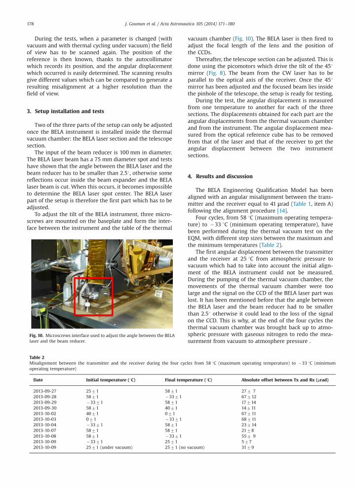
3. Setup installation and tests
Two of the three parts of the setup can only be adjustedonce the BELA instrument is installed inside the thermalvacuum chamber: the BELA laser section and the telescopesection.
The input of the beam reducer is 100 mm in diameter.The BELA laser beam has a 75 mm diameter spot and testshave shown that the angle between the BELA laser and thebeam reducer has to be smaller than 2.51, otherwise somereflections occur inside the beam expander and the BELAlaser beam is cut. When this occurs, it becomes impossibleto determine the BELA laser spot center. The BELA laserpart of the setup is therefore the first part which has to beadjusted.
To adjust the tilt of the BELA instrument, three micro-screws are mounted on the baseplate and form the inter-face between the instrument and the table of the thermal
Fig. 10. Microscrews interface used to adjust the angle between the BELAlaser and the beam reducer.
Table 2Misalignment between the transmitter and the receiver during the four cycoperating temperature)
Date Initial temperature (1C) Final temp
2013-09-27 2571 58712013-09-28 5871 �33712013-09-29 �3371 58712013-09-30 5871 40712013-10-02 4071 0712013-10-03 071 �33712013-10-04 �3371 58712013-10-07 5871 58712013-10-08 5871 �33712013-10-09 �3371 25712013-10-09 2571 (under vacuum) 2571 (no
vacuum chamber (Fig. 10). The BELA laser is then fired toadjust the focal length of the lens and the position ofthe CCDs.
Thereafter, the telescope section can be adjusted. This isdone using the picomotors which drive the tilt of the 451mirror (Fig. 8). The beam from the CW laser has to beparallel to the optical axis of the receiver. Once the 451mirror has been adjusted and the focused beam lies insidethe pinhole of the telescope, the setup is ready for testing.
During the test, the angular displacement is measuredfrom one temperature to another for each of the threesections. The displacements obtained for each part are theangular displacements from the thermal vacuum chamberand from the instrument. The angular displacement mea-sured from the optical reference cube has to be removedfrom that of the laser and that of the receiver to get theangular displacement between the two instrumentsections.
4. Results and discussion
The BELA Engineering Qualification Model has beenaligned with an angular misalignment between the trans-mitter and the receiver equal to 41 μrad (Table 1, item A)following the alignment procedure [14].
Four cycles, from 58 1C (maximum operating tempera-ture) to �33 1C (minimum operating temperature), havebeen performed during the thermal vacuum test on theEQM, with different step sizes between the maximum andthe minimum temperatures (Table 2).
The first angular displacement between the transmitterand the receiver at 25 1C from atmospheric pressure tovacuum which had to take into account the initial align-ment of the BELA instrument could not be measured.During the pumping of the thermal vacuum chamber, themovements of the thermal vacuum chamber were toolarge and the signal on the CCD of the BELA laser part waslost. It has been mentioned before that the angle betweenthe BELA laser and the beam reducer had to be smallerthan 2.51 otherwise it could lead to the loss of the signalon the CCD. This is why, at the end of the four cycles thethermal vacuum chamber was brought back up to atmo-spheric pressure with gaseous nitrogen to redo the mea-surement from vacuum to atmosphere pressure .
les from 58 1C (maximum operating temperature) to �33 1C (minimum
erature (1C) Absolute offset between Tx and Rx (μrad)
277 76771217714147116771168711237142178557 9577
vacuum) 3179

Fig. 11. Thermal vacuum test results. The small circles are the 60 μrad BELA laser spot on Mercury's surface, the intermediate circle is the field of view ofthe BELA Engineering Qualification Model and the bigger circle is the field of view of the BELA Flight Model.
Fig. 12. Angular misalignment between the transmitter and the receiverunder vacuum without taking into account the initial alignment.
J. Gouman et al. / Acta Astronautica 105 (2014) 171–180 179
Eleven measurements were made during these fourcycles and they have shown that the test is reproducible toan accuracy of E10 μrad (Fig. 12 – measurements at�33 1C and at 58 1C). The system came back to roughlythe same position (Table 2; from 58 1C to �33 1C then
from �33 1C to 58 1C) after two cycles from the measure-ment on 2013-10-04 to the measurement on 2013-10-07(Table 2 – measurement 2013-10-07).
The maximum angular displacement between thetransmitter (BELA laser) and the receiver (RTL) was68711 μrad (over the full temperature range) (Table 2).
As one can see the measurement at 0 1C is away fromthe other measurements. Unfortunately, only one measure-ment has been made at this temperature but it is unlikelythat this measurement could be affected by an errorbecause the starting measurement at 58 1C and the finish-ing measurement at �33 1C were roughly at the positionthat was expected. A further analysis during tests with theFlight Model (FM) of the instrument should be made as itmay indicate a non-linear distortion in the system. If the FMbehaves predictably and in a similar way to the EQM, thenthe initial alignment can be adjusted to the best position inorder to maintain the BELA laser spot as near as possible tothe center of the field of view of the instrument.
Fig. 11 illustrates the results from the thermal vacuumtests. The small circles represent the 60 μrad BELA laserspot on Mercury's surface. The intermediate circle repre-sents the field of view of the BELA telescope from the EQM.
The setup has shown that the BELA laser spot stays inthe field of view of the receiver and the system is stable

J. Gouman et al. / Acta Astronautica 105 (2014) 171–180180
enough to work properly at Mercury (Fig. 11). Indeed, thealignment budget concerning the initial alignment and thethermal distortions allows an error of 133 μrad on thesystem (Table 1). The measurements performed on theEQM lead to an error of 92 μrad. In Table 1, we nowcompare our final errors to the requirements and showthat the return pulse will remain well within the field ofview selected for the instrument.
At the late stage in the programme, concern about thequality of the FM telescope led to a modification increasingthe field of view in the FM design to 530 μrad. This isshown as the larger circle.
5. Conclusions and further work
We have shown that the constructed setup is able tomeasure the angular displacement of each part of the BELAinstrument. Tests performed using the BELA EngineeringQualification Model have shown that the setup is accurateenough to characterize angular movements of the instru-ment components to an accuracy of E10 μrad.
A 91 1C (from �33 1C to 58 1C) temperature range hasbeen tested. This is the first laser altimeter which isrequired to cover this temperature range and to have beensubjected to this kind of test. The BELA instrument EQMhas been shown to be stable with respect to the environ-mental (thermal) loads expected at Mercury.
Concerning the co-alignment of the instrument, theEQM has shown that the initial alignment of the FM couldbe done to a better accuracy that was required (Table 1,item A).
Furthermore, if the FM behaves like the EQM, thealignment could be adjusted so that the BELA laser beamstays as near as possible to the center of the field of view ofthe telescope in all mission phases.
Some improvements can be made for the FM. Concern-ing the setup for the thermal vacuum tests, the beamsplitter from the BELA laser part, to split the beam into twoin order to get an overview of the beam shape, is notneeded and can be a source of measurement error. Sincewe only need the focused beam to know the angulardisplacements during the test, the beam splitter and theCCD-1 will be removed.
Acknowledgments
We acknowledge funding by the Swiss National ScienceFoundation (SNSF) (Grant no. 200020_152560). We alsothank the BELA team at DLR Berlin, at Max Planck institutefor Solar System research and at RUAG Aerospace AG fordiscussion and support.
References
[1] R. Grard, A. Balogh, Returns to Mercury: science and missionobjectives, Planet. Space Sci. 49 (2001) 1395–1407, http://dx.doi.org/10.1016/S0032-0633(01)00081-2.
[2] J. Benkhoff, J. van Casteren, H. Hayakawa, M. Fujimoto, H. Laakso,M. Novara, P. Ferri, H.R. Middleton, R. Ziethe, BepiColombo compre-hensive exploration of Mercury: mission overview and science goals,Planet. Space Sci. 58 (2010) 2–20, http://dx.doi.org/10.1016/j.pss.2009.09.020.
[3] D.E. Smith, M.T. Zuber, G.B. Jackson, J.F. Cavanaugh, G.A. Neumann,H. Riris, X. Sun, R.S. Zellar, C. Coltharp, J. Connelly, R.B. Katz,I. Kleyner, P. Liiva, A. Matuszeski, E.M. Mazarico, J.F. McGarry, A.-M. Novo-Gradac, M.N. Ott, C. Peters, L.A. Ramos-Izquierdo,L. Ramsey, D.D. Rowlands, S. Schmidt, V.S. Scott, G.B. Shaw, J.C. Smith, J.-P. Swinski, M.H. Torrence, G. Unger, A.W. Yu, T.W. Zagwodzki, The lunar orbiter laser altimeter investigation onthe Lunar Reconnaissance Orbiter mission, Space Sci. Rev. 150 (2010)209–241, http://dx.doi.org/10.1007/s11214-009-9512-y.
[4] J.B. Abshire, X. Sun, H. Riris, J.M. Sirota, J.F. McGarry, S. Palm, D. Yi,P. Liiva, Geoscience Laser Altimeter System (GLAS) on the ICESatMission: on-orbit measurement performance, Geophys. Res. Lett. 32(2005) 21, http://dx.doi.org/10.1029/2005GL024028.
[5] M.T. Zuber, D.E. Smith, S.C. Solomon, D.O. Muhleman, J.W. Head, J.B. Garvin, J.B. Abshire, J.L. Bufton, The Mars observer laser altimeterinvestigation, J. Geophys. Res. 97 (1992) 7781–7797, http://dx.doi.org/10.1029/92JE00341.
[6] J.F. Cavanaugh, J.C. Smith, X. Sun, A.E. Bartels, L. Ramos-Izquierdo, D.J. Krebs, J.F. McGarry, R. Trunzo, A.M. Novo-Gradac, J.L. Britt, J. Karsh,R.B. Katz, A.T. Lukemire, R. Szymkiewicz, D.L. Berry, J.P. Swinski, G.A. Neumann, M.T. Zuber, D.E. Smith, The Mercury laser altimeterinstrument for the MESSENGER mission, Space Sci. Rev. 131 (2007)451–479, http://dx.doi.org/10.1007/s11214-007-9273-4.
[7] E.R. Cohen, B.N. Taylor, The fundamental physical constants, Phys.Today 50 (1997).
[8] J.J. Degnan, J.F. McGarry, T.W. Zagwodzki, P.W. Dabney, J. Geiger, R.Chabot, C. Steggerda, J. Marzouk, A. Chu, Design and performance ofa 3D imaging photon-counting microlaser altimeter operating fromaircraft cruise altitudes under day or night conditions, in: U.Schreiber, C. Werner, G.W. Kamerman, U.N. Singh (Eds.), Laser Radar:Ranging and Atmospheric Lidar Techniques III, Society of Photo-Optical Instrumentation Engineers (SPIE) Conference Series, vol.4546, 2002, pp. 1–10.
[9] J.L. Bufton, Laser altimetry measurements from aircraft and space-craft, IEEE Proc. 77 (1989) 463–477.
[10] D.E. Smith, M.T. Zuber, G.A. Neumann, F.G. Lemoine, E. Mazarico,M.H. Torrence, J.F. McGarry, D.D. Rowlands, J.W. Head, T.H. Duxbury,O. Aharonson, P.G. Lucey, M.S. Robinson, O.S. Barnouin, J.F. Cavanaugh, X. Sun, P. Liiva, D.-D. Mao, J.C. Smith, A.E. Bartels,Initial observations from the Lunar Orbiter Laser Altimeter (LOLA),Geophys. Res. Lett. 37 (2010) 18204, http://dx.doi.org/10.1029/2010GL043751.
[11] T. Beck, B.S. Lüthi, G. Messina, D. Piazza, K. Seiferlin, N. Thomas,Thermal analysis of a reflective baffle designed for space applica-tions, Acta Astronaut. 69 (2011) 323–334, http://dx.doi.org/10.1016/j.actaastro.2011.03.014.
[12] A.G. Santo, R.E. Gold, R.L. McNutt, S.C. Solomon, C.J. Ercol,R.W. Farquhar, T.J. Hartka, J.E. Jenkins, J.V. McAdams, L.E. Mosher,D.F. Persons, D.A. Artis, R.S. Bokulic, R.F. Conde, G. Dakermanji,M.E. Goss, D.R. Haley, K.J. Heeres, R.H. Maurer, R.C. Moore, E.H. Rodberg, T.G. Stern, S.R. Wiley, B.G. Williams, C.-W.L. Yen,M.R. Peterson, The MESSENGER mission to Mercury: spacecraftand mission design, Planet. Space Sci. 49 (2001) 1481–1500, http://dx.doi.org/10.1016/S0032-0633(01)00087-3.
[13] N. Thomas, T. Spohn, J.-P. Barriot, W. Benz, G. Beutler, U. Christensen,V. Dehant, C. Fallnich, D. Giardini, O. Groussin, K. Gunderson,E. Hauber, M. Hilchenbach, L. Iess, P. Lamy, L.-M. Lara, P. Lognonné,J.J. Lopez-Moreno, H. Michaelis, J. Oberst, D. Resendes, J.-L. Reynaud,R. Rodrigo, S. Sasaki, K. Seiferlin, M. Wieczorek, J. Whitby, TheBepiColombo Laser Altimeter: concept and baseline design, Planet.Space Sci. 55 (2007) 1398–1413, http://dx.doi.org/10.1016/j.pss.2007.03.003.
[14] S. Chakraborty, M. Affolter, K. Gunderson, J. Neubert, N. Thomas,T. Beck, M. Gerber, S. Graf, D. Piazza, A. Pommerol, G. Roethlisberger,K. Seiferlin, High accuracy alignment facility for the receiver andtransmitter of the BepiColombo Laser Altimeter, Appl. Opt. 51 (2012)4907, http://dx.doi.org/10.1364/AO.51.004907.