
MCP!Scrubber!for!Large0Area!Picosecond! Photo0Detectors!
17
MCP Scrubber for LargeArea Picosecond PhotoDetectors Tyler Lutz 16. August 2013 Contents Page Helmholtz Coil Design 1 Vacuum Chamber and Penthouse Design 7 Appendix A: Scrubber Specifications 12 Appendix B: Pinout for feedthroughs 14 Appendix C: Port list with part numbers 15 Appendix D: Intensity profile of PenRay Hg lamp 16
Transcript of MCP!Scrubber!for!Large0Area!Picosecond! Photo0Detectors!
MCP Scrubber for Large-‐Area Picosecond Photo-‐Detectors
Tyler Lutz
16. August 2013
Contents Page
Helmholtz Coil Design 1
Vacuum Chamber and Penthouse Design 7
Appendix A: Scrubber Specifications 12
Appendix B: Pin-‐out for feedthroughs 14
Appendix C: Port list with part numbers 15
Appendix D: Intensity profile of Pen-‐Ray Hg lamp 16
Helmholtz Coil Design for MCP Scrubber
Tyler Lutz
August 16, 2013
Contents
1 Overview 1
2 Electron Trajectories 2
3 Analysis 33.1 Initially Stationary Electrons . . . . . 33.2 Accounting for Initial Velocities . . . . 43.3 Frequency of Oscillating Magnetic Field 5
4 Uniformity of Magnetic Field 5
5 Conclusion 6
Abstract
We would like to build a device which scrubs mul-tichannel plates (MCP’s) by bombarding them withelectrons. When light above a certain energy thresh-old strikes a metal, electrons are liberated from themetal by the photoelectric effect; we propose to ac-celerate these photoelectrons towards MCP’s usingan electric field. In order to ensure that the electronsare distributed over the plates with reasonable unifor-mity and to smear out any “hot-spots” which mightdevelop, we apply a dithering magnetic field in theregion between the MCP’s and the electron source us-ing two pairs of Helmholtz coils. If the magnetic fieldis too weak we will see minimal spread of electrons; anexcessively strong magnetic field will cause the elec-trons to either miss the MCP’s altogether or curl backup to the metal layer from which they were liberated.The focus of this paper is on determining the dimen-sions of the device—specifically, the strength of themagnetic field, the distance from the electron source
to the target MCP’s, the frequency of oscillation inthe magnetic fields, and the radius and separation ofthe coils—which optimize both the spread and fluxof electrons on the MCP’s.
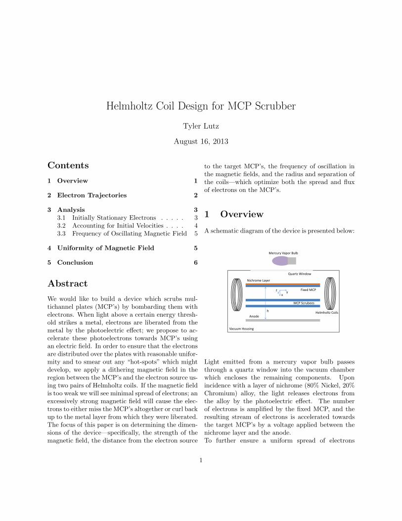
1 Overview
A schematic diagram of the device is presented below:
h
Mercury Vapor Bulb
Anode
Vacuum Housing
Helmholtz Coils
Nichrome Layer
Fixed MCP
MCP Scrubees
Quartz Window
xyz
Light emitted from a mercury vapor bulb passesthrough a quartz window into the vacuum chamberwhich encloses the remaining components. Uponincidence with a layer of nichrome (80% Nickel, 20%Chromium) alloy, the light releases electrons fromthe alloy by the photoelectric effect. The numberof electrons is amplified by the fixed MCP, and theresulting stream of electrons is accelerated towardsthe target MCP’s by a voltage applied between thenichrome layer and the anode.To further ensure a uniform spread of electrons
1
on the scrubees, two pairs of Helmholtz coils areplaced orthogonally to each other along the edges ofthe MCP’s—these are designed to create a uniformmagnetic field between the stationary MCP and theMCP scrubees. We vary the magnitude of the fieldsin order to spread out any hot spots which mightarise.Not depicted in the diagram are the second set ofHelmholtz coils, the flange in the vacuum chambernecessary for easy removal and insertion of theMCP scrubees, the vacuum pump and electricalfeedthrough, and the spacers holding all of thecomponents in place within the vacuum chamber.
2 Electron Trajectories
In the limit of constant electron momentum (equiva-lently, in the absence of any external electric fields),electrons liberated from the nichrome layer will fol-low circular trajectories through the magnetic field.The electron trajectories deviate from circular pathsin our case since we will be applying a large accelerat-ing voltage simultaneously with the magnetic fields.To find the electron trajectories we will use the fullelectromagnetic Lagrangian, which takes both fieldsinto account.The Lagrangian for electromagnetic fields is given ingeneral by:
L =1
2m(x2 + y2 + z2)− qφ+ q(v ·A) (1)
We create the electric field by applying a voltage be-tween the nichrome plate and an anode placed be-neath the MCP’s. We can thus approximate theelectric field as that of a parallel plate capacitor;if V0 is the voltage difference between the nichromelayer and the anode and h is the separation betweenthem, we can assume a uniform electric field given byE = −V0
h x, and consequently a potential of φ = V0
h x.It can be easily checked that the following vector rep-resents the general form of the vector potential for auniform magnetic field of magnitude B0 in the z di-rection: (
−rBoy pB0x 0)
(2)
Here r and p are arbitrary parameters subject to theconstraint that r + p = 1, as allowed by gauge free-dom.Combining the electric and vector potentials gives usthe full Lagrangian for our system:
L =1
2m(x2 + y2 + z2)− q V0
hx+ q(−rBoyx+ pB0xy)
(3)From here we can proceed with the usual Lagrangianformalism. Using the coordinate system describedin the schematic drawing above, the kinematic equa-tions in the z direction are:
∂L∂z
= 0 (4)
d
dt
∂L∂z
= mz (5)
So the electrons experience no net force in the zdirection—the only contribution to z motion will bethe electrons’ initial velocities in that direction. Thex direction tells a different story:
∂L∂x
= q(−V0h
+ pB0y) (6)
d
dt
∂L∂x
= mx− qrB0y (7)
Using r+p = 1, we arrive at the following differentialequation:
x− q
mB0y +
q
m
V0h
= 0 (8)
Similarly, for the y derivatives:
∂L∂y
= −qrB0x (9)
d
dt
∂L∂y
= my + qpB0x (10)
Thus:y +
q
mB0x = 0 (11)
We can now solve the system of differential equationsdefined by(8) and (11) to find time dependent equa-tions for the vertical (x) and horizontal (y) positionof the particle. Since we are primarily interested infinding the displacement in the y direction when the
2

electron strikes the MCP surface, we will consider anelectron which is at the origin at t=0; in this case y(t)will be equal to the displacement. Our assumptionof uniformity in the electric and magnetic fields war-rants the assumption that electrons will be displacedby roughly this amount regardless of where they arereleased on the nichrome layer.The only two other initial conditions are the startingvelocities in the x and y directions, which we labelas vx0 and vy0, respectively. These are determinedby the residual energy of the electron as it exits theMCP; we will show later that typical initial energieshave a comparatively small effect on the electron tra-jectories
If we let E0 = V0
h and R = em (e is the absolute
value of the charge of the electron), the complete so-lution to the system of equations is:
x(t) =vx0 sin(RB0t)
RB0+
(Γ)(
cos(RB0t)− 1)
RB0(12)
y(t) =vx0(1− cos(RB0t)
)RB0
+
(Γ)
sin(RB0t)
RB0+E0
B0t
(13)where
Γ = vy0 −E0
B0(14)
3 Analysis
3.1 Initially Stationary Electrons
We begin by considering the case where the initialelectron velocities are negligible—that is, we set vx0and vy0 in both (12) and (13) equal to zero. Thissimplifies things considerably:
x(t) =−E0
(cos(RB0t)− 1
)RB2
0
(15)
y(t) =−E0 sin(RB0t)
RB20
+E0
B0t (16)
This corresponds to an epicycloidal trajectory;the following plot shows the path of an elec-tron which starts at the origin and travels
from the emitting source layer at x=0 to-wards the MCP in the positive x direction.
0.000 0.005 0.010 0.015 0.020 0.025 0.030 0.035Distance from Cathode [m]
0.00
0.02
0.04
0.06
0.08
0.10
0.12
Late
ral D
ispla
cem
ent
[m]
Lateral Displacement as a function of Separation from Cathode
The electron reaches a maximum displacement inthe vertical direction before curving back towardsthe nichrome. At t = π
RB0, the electron attains its
apogee in the x direction:
xmax =2E0
RB20
(17)
The maximum displacement, d, in the y directionbefore the electron curls back towards the cathode issimply y( π
RB0), or:
d =πE0
RB20
(18)
We know R to be 1.759 × 10¹¹C/kg, and we will beworking in a voltage range from 200V to a few kV;we can thus simply input a desired value for d to de-termine B0 and hence the necessary MCP-to-sourceseparation. Our MCP is 20cm x 20cm, so d will be onthe order of about 5cm. We will arrange the MCP’sand anode such that there is 600V potential differencebetween the electron source and the target MCP (ofcourse, this implies a higher overall voltage difference
3
between the nichrome and the anode–the exact valueof this higher voltage is determined by the distancebetween the nichrome and the anode).Plugging these values in to (18) and (17) gives usa separation of the MCP from the nichrome of 3.18cm and a maximum B0 of 0.00259 T (less deflectionwill be seen as the magnetic field shrinks from thisvalue). Of course, we could bring the MCP closer tothe electron source and use a higher magnetic fieldto compensate for it in order to still achieve a de-flection of 5cm. Alternatively, we could pull it far-ther away from the nichrome layer and use a lowermagnetic field. The calculation is the same in bothcases—once we’ve specified the later displacement dand the nichrome-to-target MCP separation xmax,we can solve for B0 and V0, which we can adjust asnecessary.
3.2 Accounting for Initial Velocities
Our goal here is to smear out the electrons acrossthe MCP without losing too many of them—electronswhich miss the MCP surface altogether or curl backto the cathode do not contribute to the scrubbing.The results of the preceding section apply to the casewhere the photoelectron has given up all of its energyin the process of escaping and, importantly, are alsovalid for electrons with initial velocities strictly in thez direction. We need to consider however three ad-ditional extreme cases: initial velocity in the positiveand negative y directions as well as initial velocity inthe x direction (we assume that electrons with initialvelocities purely in the negative x direction are im-mediately reabsorbed by the nichrome).Our first task is to determine the range of speeds wecan reasonably expect the electrons to have. For thepurpose of finding a reasonable estimate, let’s assumethat there is no fixed MCP present and pretend thatthe electrons released from the nichrome are the onesaccelerated to the target MCP’s. Depending on thecleanliness of the surface of the nichrome, work func-tions range from 5 to 8 eV. If we use a mercury-vaporbulb to illuminate the nichrome, the main source ofphotons capable of kicking electrons off the surfaceof the nichrome will be photons at a wavelength of185nm. The maximum residual energy we can ex-
pect will thus be the energy of the 185nm photonsminus a 5.1 eV workfunction—an electron with thisresidual energy (around 1.6 eV) will have a velocityof 7.5 × 10⁵m/s. Of course, this initial velocity canbe oriented in any direction, but we will only con-sider here the limiting cases of purely axial motion.For purposes of comparison, note that the electronreleased from rest will have an energy of 600 eV bythe time it reaches the MCP; heuristically, an initialexcess energy of 1.6 eV (or even 5eV, which is typicalfor secondary electrons in general) should have littleeffect on the final displacement values—let’s checkthis hypothesis.Our primary concern is to ensure that electrons withinitial velocities in the xy plane can still contributeto scrubbing; of the four cases considered in this pa-per (no x or y momentum and purely axial motion inthe xy plane), we should pick parameters for whicheven the initial conditions which lead to the lowestmaximum x displacement still hit the MCP.The electron’s maximum displacement in the hatxdirection as a function of the angle, α, of the initialvelocity in the xy plane is given by:
xmax(α) = v0cos2(α) + P 2 − P
√Q
RB0
√Q
(19)
where:
P = sinα− E0
B0v0(20)
and
Q = cos2(α) + P 2 (21)
For the parameters we specified above and us-ing an initial velocity of 7.5 × 10⁵m/s, we getthe following plot of maximum displacement onx axis as a function of the angle of the ini-tial velocity in the xy plane from the x axis:
4
100 50 0 50 100Angle of Initial Velocity from x Axis [deg]
0.028
0.029
0.030
0.031
0.032
0.033
0.034
0.035
0.036
Maxim
um
Dis
pla
cem
ent
in x
Dir
ecti
on [
m]
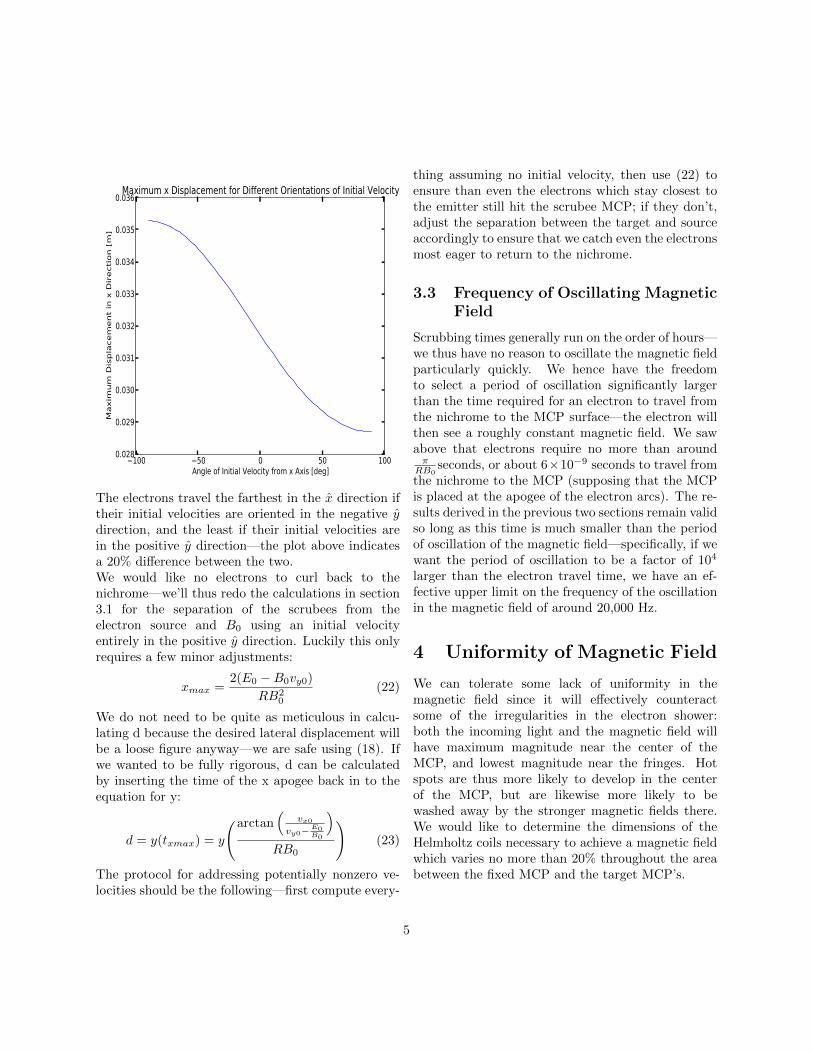
Maximum x Displacement for Different Orientations of Initial Velocity
The electrons travel the farthest in the x direction iftheir initial velocities are oriented in the negative ydirection, and the least if their initial velocities arein the positive y direction—the plot above indicatesa 20% difference between the two.We would like no electrons to curl back to thenichrome—we’ll thus redo the calculations in section3.1 for the separation of the scrubees from theelectron source and B0 using an initial velocityentirely in the positive y direction. Luckily this onlyrequires a few minor adjustments:
xmax =2(E0 −B0vy0)
RB20
(22)
We do not need to be quite as meticulous in calcu-lating d because the desired lateral displacement willbe a loose figure anyway—we are safe using (18). Ifwe wanted to be fully rigorous, d can be calculatedby inserting the time of the x apogee back in to theequation for y:
d = y(txmax) = y
(arctan(
vx0
vy0−E0B0
)RB0
)(23)
The protocol for addressing potentially nonzero ve-locities should be the following—first compute every-
thing assuming no initial velocity, then use (22) toensure than even the electrons which stay closest tothe emitter still hit the scrubee MCP; if they don’t,adjust the separation between the target and sourceaccordingly to ensure that we catch even the electronsmost eager to return to the nichrome.
3.3 Frequency of Oscillating MagneticField
Scrubbing times generally run on the order of hours—we thus have no reason to oscillate the magnetic fieldparticularly quickly. We hence have the freedomto select a period of oscillation significantly largerthan the time required for an electron to travel fromthe nichrome to the MCP surface—the electron willthen see a roughly constant magnetic field. We sawabove that electrons require no more than aroundπ
RB0seconds, or about 6×10⁻⁹ seconds to travel from
the nichrome to the MCP (supposing that the MCPis placed at the apogee of the electron arcs). The re-sults derived in the previous two sections remain validso long as this time is much smaller than the periodof oscillation of the magnetic field—specifically, if wewant the period of oscillation to be a factor of 104
larger than the electron travel time, we have an ef-fective upper limit on the frequency of the oscillationin the magnetic field of around 20,000 Hz.
4 Uniformity of Magnetic Field
We can tolerate some lack of uniformity in themagnetic field since it will effectively counteractsome of the irregularities in the electron shower:both the incoming light and the magnetic field willhave maximum magnitude near the center of theMCP, and lowest magnitude near the fringes. Hotspots are thus more likely to develop in the centerof the MCP, but are likewise more likely to bewashed away by the stronger magnetic fields there.We would like to determine the dimensions of theHelmholtz coils necessary to achieve a magnetic fieldwhich varies no more than 20% throughout the areabetween the fixed MCP and the target MCP’s.
5
The magnetic field produced by a length of wirecan be found using the Biot-Savart law, given by:
B(r) =Iµo4π
∫dr’× (r− r’)
|r− r’|3(24)
We’ll focus on integrating over one loop at a time,and then add the results together at the end. If theradius of the wire loop is a, the loop is defined incylindrical coordinates with the origin at the centerof the loop by r’ = aρ, so we have dr’ = aϕdϕ. Forthe numerator of the integrand, we have:
dr’× (r− r’) = aϕdϕ× (zz + ρρ− aρ) (25)
Here z and ρ refer to the position between thecoils where we would like to determine the magneticfield. We can ignore the angular position because wehave the freedom to redefine the coordinate systemso that ϕ, the angular position of the point we areevaluating, is zero.
Simple geometry gives us the denominator. Thefull integral we need to investigate is:
B(r) =Iµo4π
2π∫0
(a2 − ρa)z + azρ(z2 + ρ2 + a2 − 2ρa cos(θ)
) 32
dϕ
(26)Solving this abstractly is not necessary: it sufficesto vary the inputs and see what outputs they gener-ate. We desire Helmholtz coils capable of creating amagnetic field which varies by less than 20% in theregion between the fixed MCP and the first targetMCP. Since we can expect the widest variation inmagnetic field strength to be between the center ofthe region and the corner, we can simply calculatethe magnetic fields in these two points and search forsuitable parameters for the Helmholtz coil which giveus the desired 20% variance.Four integrals must be computed for each set of pa-rameters: two possible directions of magnetic fieldwithin the plane of the MCP (we ignore any verti-cal components of the magnetic field since they areparallel to the motion of the electrons and hence donot deflect them) need to be computed for both sidesof the Helmholtz coil pair. We add the components
of the magnetic field in each of the planar directionsfrom the two coils individually, then find the totalmagnitude of the field in the plane of the MCP bysquaring, adding, and taking the square root of theplanar components. Mathematically, the total fieldin the plane is:√
(By,leftcoil +By,rightcoil)2 + (Bz,leftcoil +Bz,rightcoil)2
(27)Recall that the z and y directions are in the plane ofthe MCP surface—the vertical x components are ig-nored since they are effectively parallel to the motionof the electrons. Letting rho=10cm (the axial dis-tance from the center axis of the coil to the corner ofthe plate), z=5cm (the distance of the side edge of theplate to the plane defined by the coil) and a=30cm(the radius of the coil) gives us a twenty percent re-duction in the magnetic field at the corner relativeto the center of the MCP—the magnetic field at thecorner of the MCP is 80.28% of the magnitude of thefield at the center of the MCP.
5 Conclusion
Given a desired lateral electron displacement distanced, we have generated a means of determining the nec-essary magnetic field and source to MCP distance. Ifwe have 600V between the fixed MCP and the targetMCP, we should separate the fixed MCP from thetarget MCP by about 1.5”, and use a magnetic fieldof 0.002T. To maximize the uniformity of the mag-netic field, we propose using Helmholtz coils with aradius and separation of 30cm. Our results are validfor slowly oscillating magnetic fields, with frequencieslower than 20,000Hz; in practice, we will be using fre-quencies on the order of a Hertz or less.
6
MCP Scrubber Vacuum Chamber and Penthouse
Design Details
Tyler Lutz
August 16, 2013
Contents
1 Light Source 71.1 Bulb . . . . . . . . . . . . . . . . . . . . . . . . . . . . . . . . . . 71.2 Light Housing (Penthouse) . . . . . . . . . . . . . . . . . . . . . 8
2 Vacuum Chamber 82.1 Outer Housing . . . . . . . . . . . . . . . . . . . . . . . . . . . . 82.2 Quartz Viewport . . . . . . . . . . . . . . . . . . . . . . . . . . . 92.3 Snout . . . . . . . . . . . . . . . . . . . . . . . . . . . . . . . . . 92.4 Flanges and Feedthroughs . . . . . . . . . . . . . . . . . . . . . . 9
3 Anode 93.1 Voltage . . . . . . . . . . . . . . . . . . . . . . . . . . . . . . . . 93.2 Readout . . . . . . . . . . . . . . . . . . . . . . . . . . . . . . . . 9
4 Internal Structure 10
5 Fixed MCP 10
6 Helmholtz Coils 106.1 Dimensions . . . . . . . . . . . . . . . . . . . . . . . . . . . . . . 106.2 Varying Intensity . . . . . . . . . . . . . . . . . . . . . . . . . . . 11
1 Light Source
1.1 Bulb
Light is supplied by a mercury vapor bulb. Most of the light is of too low ofan energy to liberate photoelectrons in the nichrome layer, but mercury has alarge flux peak of photons at 184nm, which indeed provides sufficient energy tokick electrons out of the metal.We currently possess a mercury vapor bulb that runs on 175 watts (Philips
7

ED28 clear), including the necessary Mogul base adapter. We have as well aPen-Ray mercury vapor bulb (including dedicated power source), which is theindustrial standard for scrubbers.Appendix D details the intensity profile of the Pen-Ray lamp; happily, thelamp can be arranged so that the light is very nearly uniform over a plane(the intensity profile is rectangular, so the lamp could be arranged so that theintensity increases as one moves away from the midpoint of the MCP).
1.2 Light Housing (Penthouse)
UV light of the wavelength range necessary to excite photoelectrons from thenichrome is strongly attenuated by oxygen but not by nitrogen. We thus floodthe space around the light bulb with nitrogen gas. In order to utilize as muchlight from the bulb as possible, we shape highly reflective aluminium into aparabola and fit it around the bulb. Sheets of cost-effective reflective aluminiumsheets are available from http://www.anomet.com/ (we haven’t ordered any asof 16. August 2013)The penthouse itself is a 5” high cylindrical chamber with an inner diameterof 7.5”. Two swageloks are installed on opposite sides of the cylinder to allowinflow and outflow of nitrogen gas, respectively, and one port for each of thelight sources is welded on the cylinder as well. We plan to only have one lightsource (Hg lamp or Pen-Ray) installed at a time. The electrical feedthrough forthe Pen-Ray is selected to have extra pins for a thermocouple (see pin-out listin separate document for details).Since the penthouse is never subjected to a vacuum, we use KF (we have KF40and KF50 aluminium half nipples) flanges for the ports, and bolt it to the topof the main vacuum chamber using a rubber flat gasket. The penthouse and itsassociated ports is constructed out of aluminium.
2 Vacuum Chamber
2.1 Outer Housing
For simplicity, we opt for a cylindrical outer housing for the vacuum chamber.In the present design, the chamber, including all flanges (but not the bolts), willbe 11.28 inches high and have an 8” inner diameter. The chamber is constructedentirely out of stainless steel, and uses CF flanges so that we can subject it toa high vacuum.Copper gaskets for the CF flanges have been ordered, but an order for the bolts,the cylindrical component, and the ports still needs to be placed. We currentlypossess two 16.5” OD CF blank flanges and four 16.5”OD CF flange rings (MDCpart numbers 110040 and 110039, respectively).
8
2.2 Quartz Viewport
A quartz viewport separates the vacuum chamber from the light source. Thewindow itself is circular, with a diameter of 4” and a thickness of 1/4”, and itis mounted on a CF flange with a 6” outer diameter. The flange is bolted ontothe vacuum chamber so that it extends over a circular hole in the upper flangeof the vacuum chamber. An opaque metal screen with a square hole cut intocan be placed on top of the window to ensure that the light passing through thewindow lands only on the fixed MCP. The Quartz Viewport has been orderedfrom MDC (p/n 1001801) and is on its way as of 16. August 2013. Any opaquescreens will be designed and constructed once the dimensions of the vacuumchamber have been finalized.
2.3 Snout
A snout is installed in the side of the cylinder to allow for the easy insertion andremoval of the target MCP’s. Since the door of the snout is opened and closedfrequently, it is sealed with an o-ring. A vacuum is established in the mainchamber by pumping though a port in the snout as well as through a vacuumport in the main chamber. In the present design, the snout opening is is 10”wide, and 4” tall. It extents 11.53” out from the central axis of the vacuumchamber.
2.4 Flanges and Feedthroughs
In addition to the flanges necessary to establish a vacuum, the vacuum chamberhas ports for electrical feedthroughs for the components described below. A fulllist of ports and feedthroughs is compiled in a separate document.
3 Anode
An 8”x8” anode is placed inside the vacuum chamber, on top of the bottomblank flange.
3.1 Voltage
A voltage between 200V and a few kV is established between the fixed MCPand the anode by a voltage source located outside the vacuum chamber. Thevoltage source is connected to the components inside the vacuum chamber viathe vacuum feedthroughs (see separate pin-out list).
3.2 Readout
One ammeter is attached to each of the anode strips to allow us to monitor theelectron shower on the anode and hence probe the uniformity of the scrubbing.The ammeters are placed outside of the vacuum chamber between the vacuum
9
feedthrough and the voltage source. We haven’t yet ordered any ammeters, butthey are easy to come by.Our current design for the vacuum chamber includes an extra port for theanode readouts, in case we should desire to read both sided of the anode stripssimultaneously.
4 Internal Structure
An internal metal scaffold holds the target MCP’s in place between the fixedMCP and the anode. The details of the metal structure still need to be fleshedout, but my proposal is the following: we could have an open metal frame (cas-sette) into which the target MCP can be installed, consisting of four L-shapedmetal rods welded into a square (the MCP sits on the lower leg of the L). Thewires supplying voltage to the MCP are attached to the MCP while it is sit-ting in the frame, and the frame itself is attached to rollers (like a drawer in acabinet) which allow us to slide it out of the chamber through the snout to re-move/install MCP’s. Once the wires are attached to the target MCP, we simplyslide it into place and close the snout door. Springs can be attached betweenthe high voltage wires and the vacuum chamber walls to ensure that the wiresdon’t get in the way of the electron shower on the target MCP.Insulated pads between the metal structure and the target MCP’s prevent any-thing from shorting. The fixed MCP is clamped to tabs welded into the innersurface of the vacuum chamber. In the current design, the target and fixedMCP’s are separated by 2”.
5 Fixed MCP
The fixed MCP is coated with a thin layer of nichrome (80% nickel, 20%chromium) in order to convert the incident photons into photoelectrons. Thework function of nichrome is between 5.1 and 8 eV, depending on the clean-liness of the surface. The fixed MCP provides a gain of around 105, and theelectrons exiting the MCP are then accelerated to the target MCP’s along auniform electric potential gradient.
6 Helmholtz Coils
The design of the coils is described in a separate document—we summarize herethe highlights:
6.1 Dimensions
In order to achieve a magnetic field of 0.00259T which varies by no more than80% over the surface of the target MCP, we construct Helmholtz coils with aradius of 12 inches and separated by 12 inches consisting of 43 loops of wire
10
with 20 amps of current passing through them. Using the equations derived inthe attached document detailing the design of the Helmholtz coils, the voltagebetween the fixed MCP and the target MCP needs to be adjusted to ensure thatthe electrons from the fixed MCP don’t curl back to their source—in practice avoltage in the range of 450V to 600V sill suffice for this purpose given the presentconfiguration (fixed to target MCP separation of 2”). The Helmholtz coils willbe placed outside the vacuum chamber but rigidly attached to it, potentially bywooden dowels.The Helmholtz coils still need to be constructed as of today—We have a largeplastic tube that we can use to provide a circular structure for the loops ofwire. Coils of the dimensions needed are not widely available commercially, andcustom-ordered coil pairs run in the vicinity of $5000.
6.2 Varying Intensity
The current in the Helmholtz coils is supplied by two triangular pulse genera-tors, with one supplying the current to each pair. In order to evenly spread outthe electrons over a square area, the frequencies of the two triangular pulse gen-erators are set to be close to each other but not exactly equal. The frequenciesof the pulses will be small, on the order of a Hertz or less.Reasonably-priced triangular waveform generators can be purchased from:http://www.karlssonrobotics.com/cart/frequency-generator-kit-fg085/
11
Appendix A: Desired MCP Scrubber Specifications
Tyler Lutz
August 16, 2013
1 Light Source
1.1 Bulb
The work function of Nichrome runs between 5.1 and8 eV, depending on the cleanliness of the surface.We thus seek light with a wavelength lower thanabout 245nm. Mercury vapor bulbs offer a largeflux of light at 185nm. A more expensive alternativewould be to use Pen-Ray lamps, which is generallyaccepted as the industrial standard for scrubbers.The bulb we currently have runs on 175 Watts andrequires a Mogul base.
Specifications:
1. The bulb needs to be able to run continuouslyfor at least 5 hours at a time.
2. The bulb should have a reasonably long lifetime,ideally on the order of 10,000 hours or more.
3. The bulb must be able to emit UV light withwavelength below 245nm.
1.2 Light Housing
We would ideally like to flood the Nichrome surfacewith perfectly uniform UV light; though we will laterbe using Helmholtz coils to make the electron showeron the MCP’s more uniform, we should strive tomake the light incident on the nichrome as uniformas possible first. We would also like to maximize theflux of UV light into the vacuum chamber.
Specifications:
1. The light source(s) and housing should be ar-ranged to transmit a sufficient quantity of UVlight into the vacuum chamber so that the scrub-bing can be effected in less than 10 hours.
2. The intensity of the light incident on thenichrome surface should vary by less than 10%across the surface.
Both items can be simultaneously accomplished usingmultiple light sources and a suitably designed reflec-tive surface inside the light housing. An additionalconsideration is that UV light in the wavelengths weare considering is strongly attenuated by oxygen; acommon industrial solution is to fill the space aroundthe bulb with nitrogen, which is transparent to UVlight in the range from 150 to 200nm.
2 Vacuum Chamber
2.1 Dimensions
1. The vacuum chamber can have either a rectangu-lar or circular horizontal cross-section; in eithercase, it needs to be able to accommodate an 8×8in. MCP lying flat inside it.
2. The vacuum chamber must be at least tallenough to accommodate:
(a) a fixed MCP with a layer of Nichrome coat-ing its upper surface
(b) as many as three MCP’s to be scrubbed
(c) a space of around 2 inches between the fixedMCP and the scrubees to allow a ditheringmagnetic field created in this space to suf-ficiently spread out the electrons.
12
(d) an anode, placed beneath the lowest MCPin the vacuum chamber
(e) any housing necessary to keep the afore-mentioned items in place
(f) a space between the fixed MCP and thequartz window to allow the incoming lightto spread out (and thereby better ensureuniformity of the light incident on thenichrome).
Item (f) above depends crucially both on the rawuniformity of light from the source and on the di-mensions of the quartz window as detailed below.
2.2 Window
A window separates the inner vacuum chamber fromthe light.
Specifications:
1. The window be sufficiently thick to withstandatmospheric pressure on one side and a vacuumon the other.
2. The window should transmit more than 50% ofthe UV light from the light source into the vac-uum chamber. These are the two driving con-straints on the dimensions of the window: inpractice, it would be possible to reinforce thewindow by installing a metal mesh or supportdirectly beneath the window.
3. The window should be no larger than 8 × 8 in.,and should ideally be smaller such that it onlytransmits a section of the full spatial intensityprofile of the light source which is highly uniformin intensity.
A smaller and hence thinner window can be used ifwe are able to place the light source very close toit. Smaller windows, however, force us to place moredistance between the window and the MCP in thevacuum chamber to allow the light to fan out to thefull 8 × 8 area of the fixed MCP.
2.3 Flanges and Feedthroughs
1. We need to be able to easily insert and removetarget MCP’s into the vacuum chamber.
2. Wires need to pass through the walls of the vac-uum chamber in order to establish a voltage be-tween the fixed MCP and the anode, and to sup-ply the Helmholtz coils with current.
The former can be accomplished by attaching a sidechamber to the vacuum chamber ending in a remov-able blank rectangular flange. To satisfy the latter,vacuum feedthroughs can easily be built into the vac-uum chamber walls.
3 Anode
3.1 Voltage
A voltage of between 200V and a few kV needs tobe established between the fixed MCP and the anodelying beneath the target MCP’s.
3.2 Readout
We would ideally like to be able to do a current read-ing over the strips of the anode in order to probethe uniformity of the electron stream on the targetMCP’s.
4 Helmholtz Coils
Need to be arranged to create a uniform magneticfield of around 0.002 Tesla in the space between thefixed MCP and the target MCP’s. This will requirea current of a few amps.
4.1 Varying Intensity
The magnetic fields need to smear out the incom-ing electrons over a large surface—we thus vary themagnetic fields by sending triangular pulses into thepairs of Helmholtz coils. The triangular waveformswill have frequencies that are slightly different fromeach other.
13
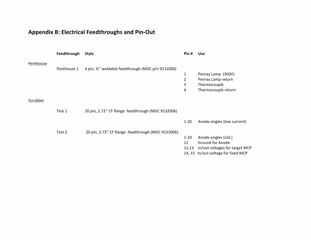
Appendix B: Electrical Feedthroughs and Pin-‐Out
Feedthrough Style Pin # Use
Penthouse Penthouse 1 4 pin, ¾’’ weldable feedthrough (MDC p/n 9131000)
1 Penray Lamp (300V) 2 Penray Lamp return 3 Thermocouple 4 Thermocouple return Scrubber Test 1 20 pin, 2.73’’ CF flange feedthrough (MDC 9132006)
1-‐20 Anode singles (low current)
Test 2 20 pin, 2.73’’ CF flange feedthrough (MDC 9132006) 1-‐10 Anode singles (ctd.)
11 Ground for Anode 12,13 In/out voltages for target MCP 14, 15 In/out voltage for fixed MCP
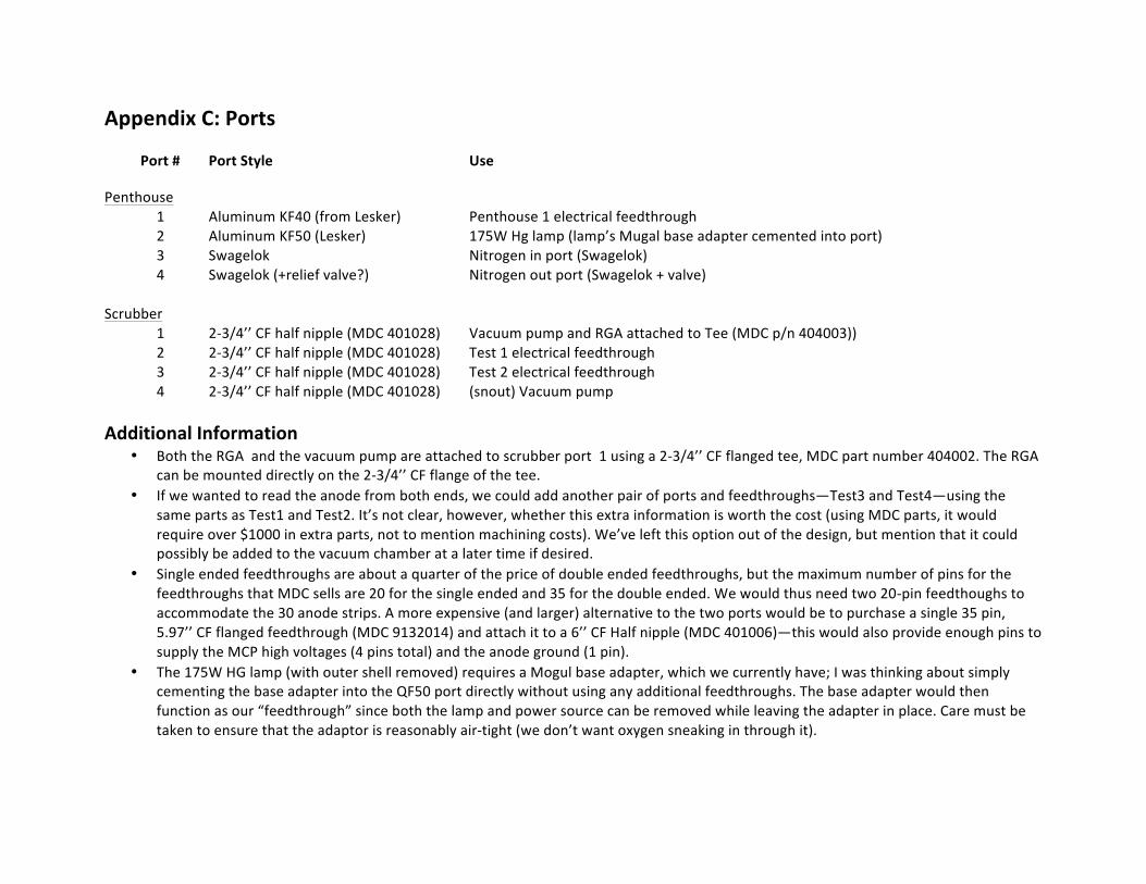
Appendix C: Ports
Port # Port Style Use
Penthouse 1 Aluminum KF40 (from Lesker) Penthouse 1 electrical feedthrough 2 Aluminum KF50 (Lesker) 175W Hg lamp (lamp’s Mugal base adapter cemented into port) 3 Swagelok Nitrogen in port (Swagelok) 4 Swagelok (+relief valve?) Nitrogen out port (Swagelok + valve) Scrubber 1 2-‐3/4’’ CF half nipple (MDC 401028) Vacuum pump and RGA attached to Tee (MDC p/n 404003)) 2 2-‐3/4’’ CF half nipple (MDC 401028) Test 1 electrical feedthrough 3 2-‐3/4’’ CF half nipple (MDC 401028) Test 2 electrical feedthrough 4 2-‐3/4’’ CF half nipple (MDC 401028) (snout) Vacuum pump Additional Information
• Both the RGA and the vacuum pump are attached to scrubber port 1 using a 2-‐3/4’’ CF flanged tee, MDC part number 404002. The RGA can be mounted directly on the 2-‐3/4’’ CF flange of the tee.
• If we wanted to read the anode from both ends, we could add another pair of ports and feedthroughs—Test3 and Test4—using the same parts as Test1 and Test2. It’s not clear, however, whether this extra information is worth the cost (using MDC parts, it would require over $1000 in extra parts, not to mention machining costs). We’ve left this option out of the design, but mention that it could possibly be added to the vacuum chamber at a later time if desired.
• Single ended feedthroughs are about a quarter of the price of double ended feedthroughs, but the maximum number of pins for the feedthroughs that MDC sells are 20 for the single ended and 35 for the double ended. We would thus need two 20-‐pin feedthoughs to accommodate the 30 anode strips. A more expensive (and larger) alternative to the two ports would be to purchase a single 35 pin, 5.97’’ CF flanged feedthrough (MDC 9132014) and attach it to a 6’’ CF Half nipple (MDC 401006)—this would also provide enough pins to supply the MCP high voltages (4 pins total) and the anode ground (1 pin).
• The 175W HG lamp (with outer shell removed) requires a Mogul base adapter, which we currently have; I was thinking about simply cementing the base adapter into the QF50 port directly without using any additional feedthroughs. The base adapter would then function as our “feedthrough” since both the lamp and power source can be removed while leaving the adapter in place. Care must be taken to ensure that the adaptor is reasonably air-‐tight (we don’t want oxygen sneaking in through it).
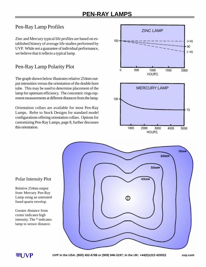
Pen-Ray Lamp Polarity Plot
The graph shown below illustrates relative 254nm out-put intensities versus the orientation of the double boretube. This may be used to determine placement of thelamp for optimum efficiency. The concentric rings rep-resent measurements at different distances from the lamp.
Orientation collars are available for most Pen-RayLamps. Refer to Stock Designs for standard modelconfigurations offering orientation collars. Options forcustomizing Pen-Ray Lamps, page 8, further discussesthis orientation.
Pen-Ray Lamp Profiles
Zinc and Mercury typical life profiles are based on es-tablished history of average life studies performed byUVP. While not a guarantee of individual performance,we believe that it reflects a typical lamp.
PEN-RAY LAMP PROFILES AND POLARITY PLOTS
Polar Intensity Plot
Relative 254nm outputfrom Mercury Pen-RayLamp using an untreatedfused quartz envelop.
Greater distance fromcenter indicates highintensity. The * indicateslamp to sensor distance.
ZINC LAMP
MERCURY LAMP
PEN-RAY LAMPS
UVP in the USA: (800) 452-6788 or (909) 946-3197; In the UK: +44(0)1223 420022 uvp.com