MCPHS Peer Review - Worcester Polytechnic Institute · MCPHS Peer Review A ... mat foundation. The...
110
MCPHS Peer Review A Major Qualifying Project Submitted to the Faculty Of the WORCESTER POLYTECHNIC INSTITUTE in partial fulfillment of the requirements for the Degree of Bachelor of Science By Dillon O’Toole April 17, 2012 Submitted To: Professor Tahar El-Korchi Professor Edward J. Swierz
Transcript of MCPHS Peer Review - Worcester Polytechnic Institute · MCPHS Peer Review A ... mat foundation. The...

MCPHS Peer Review
A Major Qualifying Project
Submitted to the Faculty
Of the
WORCESTER POLYTECHNIC INSTITUTE
in partial fulfillment of the requirements for the
Degree of Bachelor of Science
By
Dillon O’Toole
April 17, 2012
Submitted To:
Professor Tahar El-Korchi
Professor Edward J. Swierz
2
Abstract
The objective of this MQP was to review the structural design of the superstructure of an office and
academic building recently built for the Massachusetts College of Pharmacy and Health Studies. The
design included post tensioned concrete slabs, as well as reinforced concrete columns, shear walls and a
mat foundation. The design was reviewed using load resistance factor design, in accordance with the
Commonwealth of Massachusetts state building code, and accounted for both gravity and lateral loads.
The flooring system was also redesigned as an alternative steel design.

3
Acknowledgements
First and foremost I would like to thank my advisors for the project, Professor Edward J. Swierz and
Professor Tahar El-Korchi for their feedback, guidance and support. I would also like to thank Souza,
True and Partners Inc. and KSID for allowing me to access their design plans and architectural drawings.
4
Capstone Design Statement
The capstone design requirement of this project was met by proposing a redesign of the existing
floor plan with structural steel and a concrete slab on metal decking instead of post tensioned concrete.
WPI faculty and students would be interested in this comparison because it showcases the different
shape and weight constraints and structural behavior brought about by differing building materials.
Construction using steel can have a significant effect on the characteristics of a building in comparison to
concrete. This project addressed the following realistic constraints: economic, constructability, social
and political.
Economic
The cost of building a structure hinges upon the cost of building materials, as well as labor and
other such expenses. Redesigning the flooring system with steel members as well as a concrete deck
changes the weight of the building in a large way, but is not necessarily financially advantageous. The
rising price of metals in the current economic climate also has a hand to play in the pricing of any
proposed steel project.
Constructability
Constructability plays a large part in the selection of building materials and design. A scheme
may be perfectly designed to bear the proper loads, but if the shaping is too exotic it cannot be created
in a real world application. Concrete typically needs a formwork created beforehand in the shape of the
desired member. The proposed redesign is advantageous for multiple reasons. Steel members are
premade and shipped to a job site, eliminating the need for formwork to be made. The steel decking
used for the floor slabs also serve as a mold for the concrete to be poured. The concrete slab proposed
in the steel redesign also requires no post tensioning, so that step is eliminated from the construction
schedule.
5
Social
The material used also has an effect on the social and current labor markets in the surrounding
community. Any construction project has a positive boon to the surrounding community. In the New
England area there is a strong steel labor force as well as concrete, so there is a positive effect with both
material choices. Construction projects in general also provide a positive social impact to the
community through increasing the amount of jobs and sales in the surrounding area.
Political
Political issues can arise for multiple reasons during construction. These issues are usually based
on the effect construction has on the surrounding area, and not on the materials used in the
construction phase. Because of this, a redesign would not have much if any effect on the political issues
that arose from the building of this new structure.
6
Table of Contents Abstract ......................................................................................................................................................... 2
Acknowledgements ....................................................................................................................................... 3
Capstone Design Statement .......................................................................................................................... 4
Economic ................................................................................................................................................... 4
Constructability ......................................................................................................................................... 4
Social ......................................................................................................................................................... 5
Political ...................................................................................................................................................... 5
List of Tables ................................................................................................................................................. 9
Introduction ................................................................................................................................................ 10
Background ................................................................................................................................................. 12
Academic and Office Building ................................................................................................................. 12
Location ................................................................................................................................................... 12
Description .............................................................................................................................................. 13
Concrete .................................................................................................................................................. 14
Reinforced Concrete ............................................................................................................................... 15
Prestressed Concrete .............................................................................................................................. 15
Structural Steel........................................................................................................................................ 17
Loading .................................................................................................................................................... 17
Prestressed Floor system ............................................................................................................................ 18
Columns ...................................................................................................................................................... 24
7
Shear Walls ................................................................................................................................................. 28
Structural Steel Flooring System ................................................................................................................. 30
Results and Conclusions .............................................................................................................................. 37
Appendix ..................................................................................................................................................... 39
2nd Floor slab design excel sheet ............................................................................................................. 39
6th floor slab design excel spreadsheet ................................................................................................... 48
Second Floor Interior column Excel Spreadsheet ................................................................................... 55
Second Floor Exterior Middle Column Excel Spreadsheet ...................................................................... 58
2nd Floor Edge .......................................................................................................................................... 62
Shear Wall Excel Spreadsheet ................................................................................................................. 69
5th Floor Steel Beam and Girder Excel Spreadsheet ............................................................................... 72
6th Floor Steel Beam and Girder Excel Spreadsheet ............................................................................... 76
5 inch Slab and Steel Decking for 5th floor Excel Spreadsheet ................................................................ 80
5 inch Slab and Steel decking for 6th floor Excel Spreadsheet ................................................................ 86
Fifth floor Girder Design Excel Spreadsheet ........................................................................................... 92
Sixth Floor Girder Design Excel Spreadsheet .......................................................................................... 94
Fifth Floor Spandrel Beam Excel Spreadsheet ........................................................................................ 96
Sixth Floor Spandrel Beam Excel Spreadsheet ...................................................................................... 101
Fifth Floor Spandrel Girder Excel Spreadsheet ..................................................................................... 107
Sixth Floor Spandrel Girder Excel Spreadsheet ..................................................................................... 109

8
List of Figures
Figure 1: Street view of the west elevation of the MCPHS building during construction. ......................... 13
Figure 2: Post tensioning cables laid before a concrete pour..................................................................... 16
Figure 3: tendon layout for the 2nd through 5th floor slabs ...................................................................... 19
Figure 4: east-west and north-south tendon profile for the 2nd floor respectfully. The tendon reaches a
high point at the columns, and a low point at the midpoint of the slabs. The values are the depths of the
tendons at columns and midpoints. The above tendon profile is uniformly distributed while the lower
profile is banded. ........................................................................................................................................ 20
Figure 5: Column specifications .................................................................................................................. 25
Figure 6: Beam and girder layout for the 5th and 6th floor respectfully. All beams are 30 feet long and are
connected to girders on both ends. The number in parenthesis on the beams are the number of shear
studs needed. .............................................................................................................................................. 32
Figure 7: Steel decking before a concrete pour .......................................................................................... 34
9
List of Tables
Table 1: Example Moment distribution calculations.…………………………………………………………………………….21
Table 2: Factored shear and secondary moments for the fifth floor……………………………………………..……..22
Table 3: Factored shear and secondary moments for the sixth floor……………………………………………..…….22
10
Introduction
Throughout the design process, there are many decisions and calculations that affect the
accuracy and viability of the project. The risk of inaccuracies and the high cost of such errors makes
peer reviews a necessary and vital part of the design and permit process. These reviews may entail
redesigning major aspects of the building to compensate for erroneous aspects, and more importantly
to check that the engineer of record used the proper design processes and Code mandates. Calculation
accuracy and design integrity are paramount to a safe and functional structure.
The Massachusetts College of Pharmacy and Health Sciences (MCPHS) is an accredited
institution that is head quartered in Boston, MA. MCPHS is a graduate school that focuses on the
medical field. The Worcester campus hosts the accelerated pharmacy programs as well as physician
assistance studies. The Worcester campus of MCPHS is twelve years old, having been added in 2000.
This expansion is necessary to accommodate an ever growing influx of students. MCPHS recently
started building a new six story, reinforced concrete building for office, laboratory and lecture hall
purposes. This building is being constructed at 10 Lincoln square, Worcester, MA.
This project centered on a peer review of the essential aspects of the superstructure. This
report should help WPI academia understand more about the design aspects chosen for this building.
The data needed to review this structure, such as the permit and construction set of drawings design
and architectural drawings was provided by the construction management firm in charge of the stage
two renovations Souza, True and Partners. Additional code and design information was provided by the
American Concrete Institute’s ACI 318-08 manual1 and the American institute for Steel Construction’s
1 Building Code Requirements for Structural Concrete (ACI 318-08) and Commentary. Farmington
Hills, MI: American Concrete Institute, 2008. Print.

11
steel design manual2. The structural design and analysis knowledge learned from courses taken at WPI’s
department of Civil and Environmental Engineering were utilized for the completion of this project as
well.
2 Steel Construction Manual. Chicago, IL: American Institute of Steel Construction, 2007. Print.
12
Background
To complete this project, two major objectives were established. The first objective was to
review the design of the MCPHS superstructure to check for the accuracy and validity of the design. The
second was to redesign the flooring systems using structural steel as opposed to concrete. Before these
two objectives could be achieved, information such as loading and usage, the original design and the
applicable building codes were also needed. Once these items were obtained, the design could be
reviewed, and found to be either adequate and ready for construction, or recommendations could be
made that would make the building feasible and code compliant. In order to understand this project
completely, this chapter on the background of the project is presented.
Academic and Office Building
The Massachusetts College of Pharmacy and Health studies recently needed to add a new
building to its Worcester campus to accommodate larger demand for the college’s programs. The
Worcester campus hosts the accelerated pharmacy programs as well as physician assistance studies and
other graduate studies. This upgrade of the campus should act as a boon to both the institution and
surrounding areas of Worcester.
Location
MCPHS’s new building is located on the same plot of land as another MCPHS building. The
location is 10 Lincoln Square, in Worcester MA. This building is part of an effort to add more capacity to
MCPHS’s Worcester campus. The building can be seen at its Lincoln Square location in figure 1 below.
This building should also allow for expansion of the accelerated programs offered in the Worcester
campus.
13
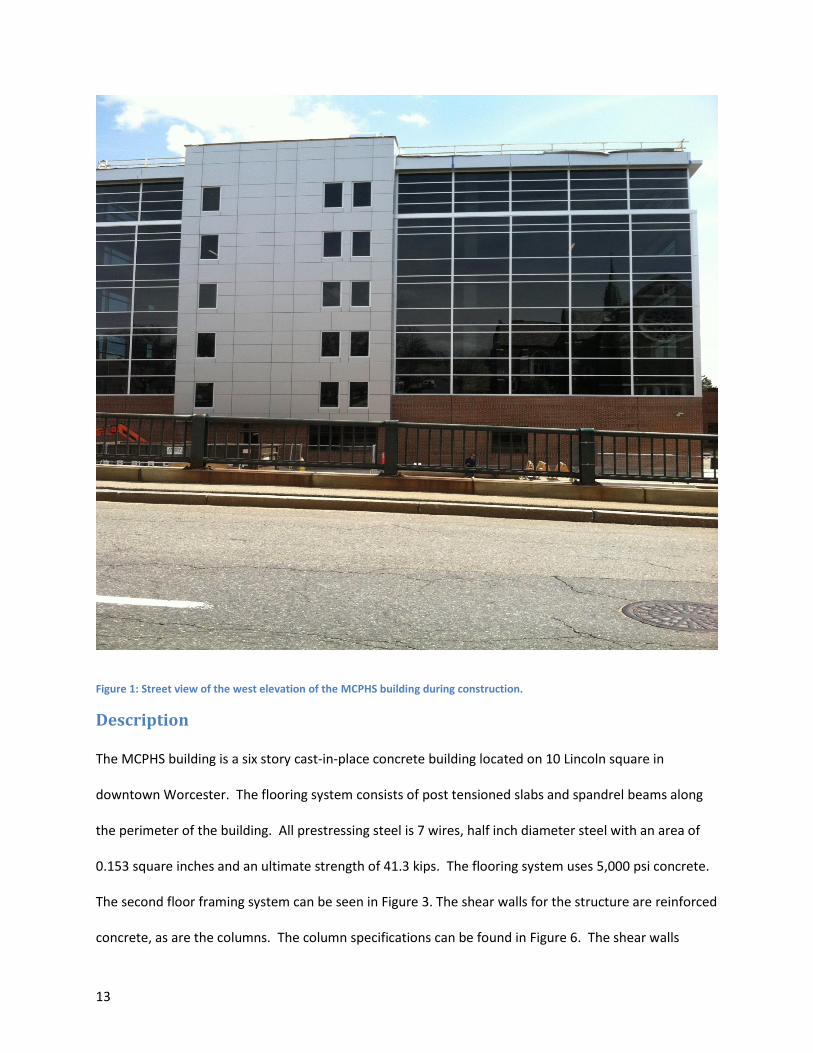
Figure 1: Street view of the west elevation of the MCPHS building during construction.
Description
The MCPHS building is a six story cast-in-place concrete building located on 10 Lincoln square in
downtown Worcester. The flooring system consists of post tensioned slabs and spandrel beams along
the perimeter of the building. All prestressing steel is 7 wires, half inch diameter steel with an area of
0.153 square inches and an ultimate strength of 41.3 kips. The flooring system uses 5,000 psi concrete.
The second floor framing system can be seen in Figure 3. The shear walls for the structure are reinforced
concrete, as are the columns. The column specifications can be found in Figure 6. The shear walls
14
provide resistance for the lateral load demand. These members also are 5,000 psi concrete. The roofing
is a pan joist and girder framing system. The foundation is a 3 foot thick, conventionally reinforced
concrete mat foundation of 4,000 psi concrete. The building will hold a lecture hall on the main floor, as
well as a large lobby, and laboratory space. The second floor will house office and administrative areas.
The upper three floors will be used for similar programmatic needs. The sixth floor has a higher loading
than the lower floors, so the slab is thicker. The façade is brick on the first floor, and glass from the
second to the sixth, except for the shear walls.
Concrete
Modern concrete is made up of multiple ingredients at a specific ratio that determines the
physical properties of the intended mix. Concrete is comprised of Portland cement, fine and coarse
aggregates, water and admixtures. These four ingredients can be combined in any number of different
ratios, which change the physical properties of the concrete. The strength of concrete can range
anywhere from 3,000 pounds per square inch, to 16,000 pounds per square inch and higher in some
markets.
Concrete is an excellent building material for anything that is under a compressive loading.
Another positive aspect of concrete is its fluid state, because concrete can be poured into any shape
imaginable, as long as the aggregate can fit and a proper mold is created. Concrete is relatively weak in
tension however. In order to combat this, steel is placed within the concrete members to take the
tensile load forces while the concrete handles compression. There are two different ways to achieve
this balance of steel and concrete in modern concrete structures, Reinforced concrete, and Prestressed
concrete.
15
Reinforced Concrete
Reinforced concrete is any concrete that has reinforcing bars to supply the required tensile
strength for the concrete member. This technique is relatively low tech and has been in existence
longer than prestressing. In reinforced concrete, the reinforcing cage is typically placed first, and then
concrete is poured, creating a structure. Once the concrete is poured, it is left to cure for roughly a
month, in order to achieve a useful strength. The reinforcement bars used in reinforced concrete are
typically 60,000 psi yield strength bars, and are available in diameter increments of 1/8 of an inch. The
largest bar that can typically be found is a #18 bar, which has a nominal diameter of 2 ¼ inches.
In the MCPHS structure, most members are reinforced concrete. The columns, shear walls and
foundation are all made from reinforced concrete, whereas the floor framing is prestressed concrete.
Prestressed Concrete
Prestressed concrete is the other modern use of concrete in structural applications. Prestressed
concrete makes use of wire strands of steel that are banded into steel tendons. These tendons are
stressed either before or after the concrete is added, and that timing of the stressing is the key
difference between prestressed and post tensioned concrete. For slab applications, the strands are
usually placed in a parabolic shape through the slab, in a shape that is similar to the bending moment
diagram of the given slab.
Pretensioning involves the strands being tensioned before the concrete is placed. Once the
concrete is sufficiently hardened, the anchors holding the strands are released, and the resulting force
adds compressive stress to the concrete. Because a strong anchoring point is needed, Pretensioning is
usually done at a plant, and then the piece is shipped to a job site.
16
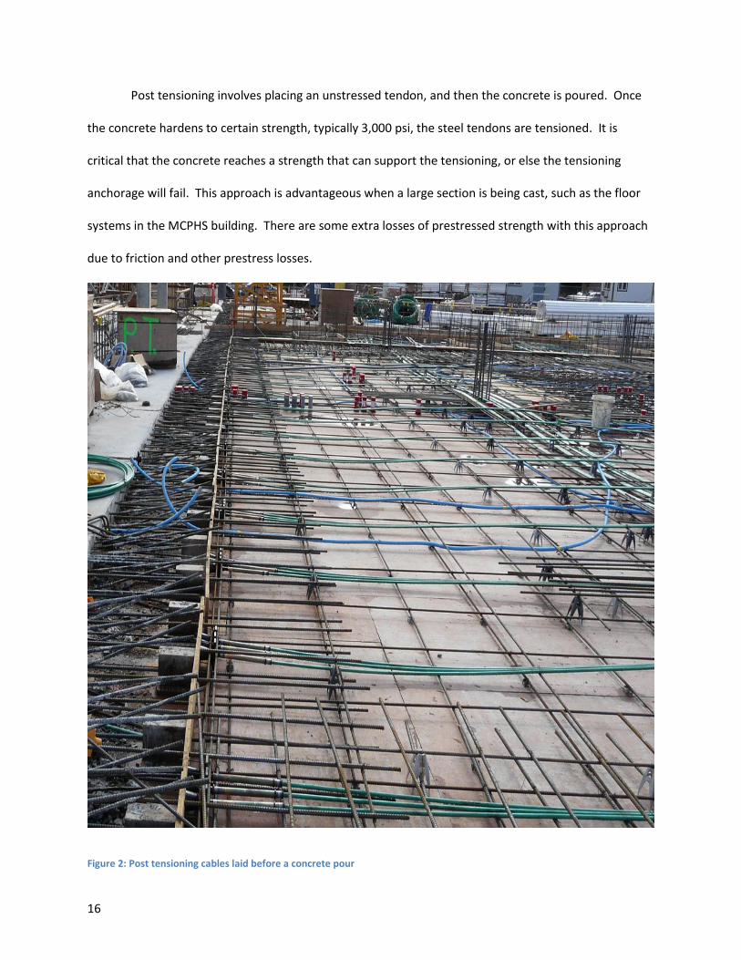
Post tensioning involves placing an unstressed tendon, and then the concrete is poured. Once
the concrete hardens to certain strength, typically 3,000 psi, the steel tendons are tensioned. It is
critical that the concrete reaches a strength that can support the tensioning, or else the tensioning
anchorage will fail. This approach is advantageous when a large section is being cast, such as the floor
systems in the MCPHS building. There are some extra losses of prestressed strength with this approach
due to friction and other prestress losses.
Figure 2: Post tensioning cables laid before a concrete pour
17
Structural Steel
Structural steel provides certain advantages that concrete does not. Firstly, steel comes in
standard industry sizes, unlike concrete that has to be molded to a certain shape. Steel can be
purchased in many different shapes, but the shape used for the beams and girders in this report were
wide flanged, or W beams. Since all the beams are manufactured to certain specifications, most
properties can be easily found in the AISC manual. Structural steel can be quick to erect if the shipments
from fabricators are timed well, and doesn’t require the lengthy curing time of concrete
Loading
When designing a structure, a critical design value needed is the loading that the structure will
undergo. The loading of any building can be broken into three groups: live loads, dead loads and
environmental loads. Live loads are any loads that are not static, such as occupants. Dead loads can be
defined as permanent loads that are typically part of the building itself. Environmental loads are any
loads that occur from the environment, such as earthquake and snow loads.
Minimum loading conditions can be found through the Massachusetts State Building Code, or
MSBC. Though the MSBC covers most loads, any loads that aren’t covered can be found in the ASCE 7
standards. ASCE 7 is a reference material offered by the American Society of Civil Engineers in which
minimum load provisions can be found. The only loads not given from MSBC and ASCE 7 are the self-
load, which is calculated from the materials, used. These loads are factored with different values in
order to add a factor of safety against limit states.
There are two different design approaches, LRFD and ASD, and each has their own load
combinations and factors. For this project LRFD, or load resistance factor design, was used. There are
multiple load combinations that can be used in different situations depending on what loads are acting
on the member. For example, a floor system would have a higher load from a combination that has a
18
higher factor for dead and live loads, so they are to be used. Once the proper loads and load
combination are found, the design of members could be performed.
Prestressed Floor system
According to the design drawings provided by the construction firm building the MCPHS
structure, the flooring slabs were 90 feet by 93 feet overall and designed as post tensioned concrete
slabs. The flooring was designed as a flat plate floor system, using techniques learned from CE 4017,
prestressed concrete design. The strength of the concrete was given as 5,000 psi, and the values of the
steel were found from design drawings.
The losses due to prestressing were found using lump sum losses, which were found in table 3.1
of Edward Nawy’s text book “Prestressed Concrete” 3. Lump sum losses do not take loss due to friction
into account, so that value had to be calculated independently and added to the lump sum losses.
These losses were subtracted from the strength in prestressed reinforcement at nominal strength to
find the stress after prestressing.
The trial thickness was found as the product of length of the slab divided by 45. Once a trial slab
thickness was found, the loads acting on the slabs were calculated. The load combination chosen for
slab design was 1.2*dead load + 1.6*live load. This combination was chosen for all six floors, as it had
the largest load. The 2nd, 3rd, 4th And 5th floors are subjected to the same loading, so they were
uniformly designed. The 6th floor was subject to a higher loading then those floors below it.
3 Nawy, Edward G. Prestressed Concrete: A Fundamental Approach. Upper Saddle River, NJ: Prentice
Hall, 2000. Print.
19
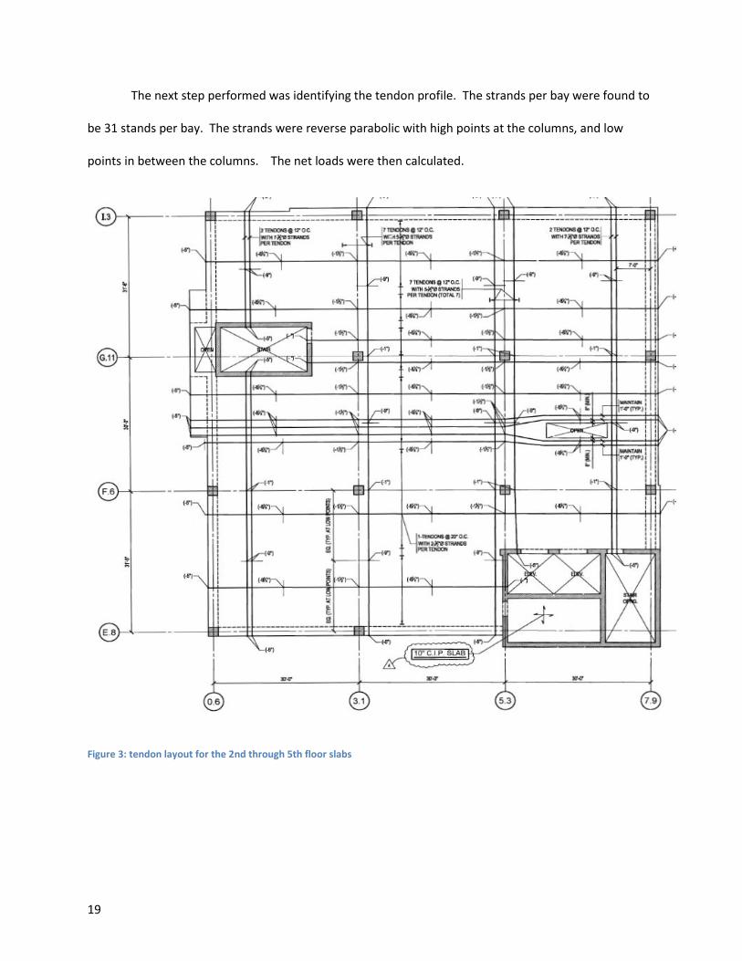
The next step performed was identifying the tendon profile. The strands per bay were found to
be 31 stands per bay. The strands were reverse parabolic with high points at the columns, and low
points in between the columns. The net loads were then calculated.
Figure 3: tendon layout for the 2nd through 5th floor slabs
20
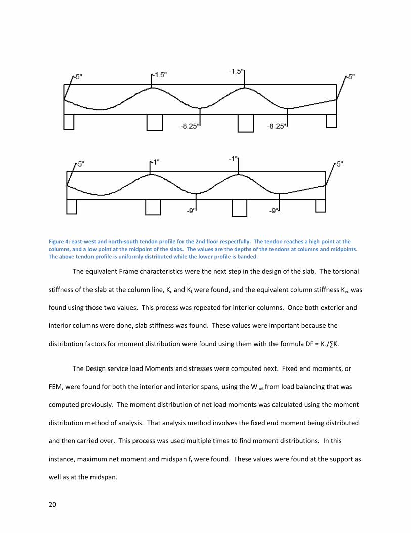
Figure 4: east-west and north-south tendon profile for the 2nd floor respectfully. The tendon reaches a high point at the columns, and a low point at the midpoint of the slabs. The values are the depths of the tendons at columns and midpoints. The above tendon profile is uniformly distributed while the lower profile is banded.
The equivalent Frame characteristics were the next step in the design of the slab. The torsional
stiffness of the slab at the column line, Kc and Kt were found, and the equivalent column stiffness Kec was
found using those two values. This process was repeated for interior columns. Once both exterior and
interior columns were done, slab stiffness was found. These values were important because the
distribution factors for moment distribution were found using them with the formula DF = Ks/∑K.
The Design service load Moments and stresses were computed next. Fixed end moments, or
FEM, were found for both the interior and interior spans, using the Wnet from load balancing that was
computed previously. The moment distribution of net load moments was calculated using the moment
distribution method of analysis. That analysis method involves the fixed end moment being distributed
and then carried over. This process was used multiple times to find moment distributions. In this
instance, maximum net moment and midspan ft were found. These values were found at the support as
well as at the midspan.
21
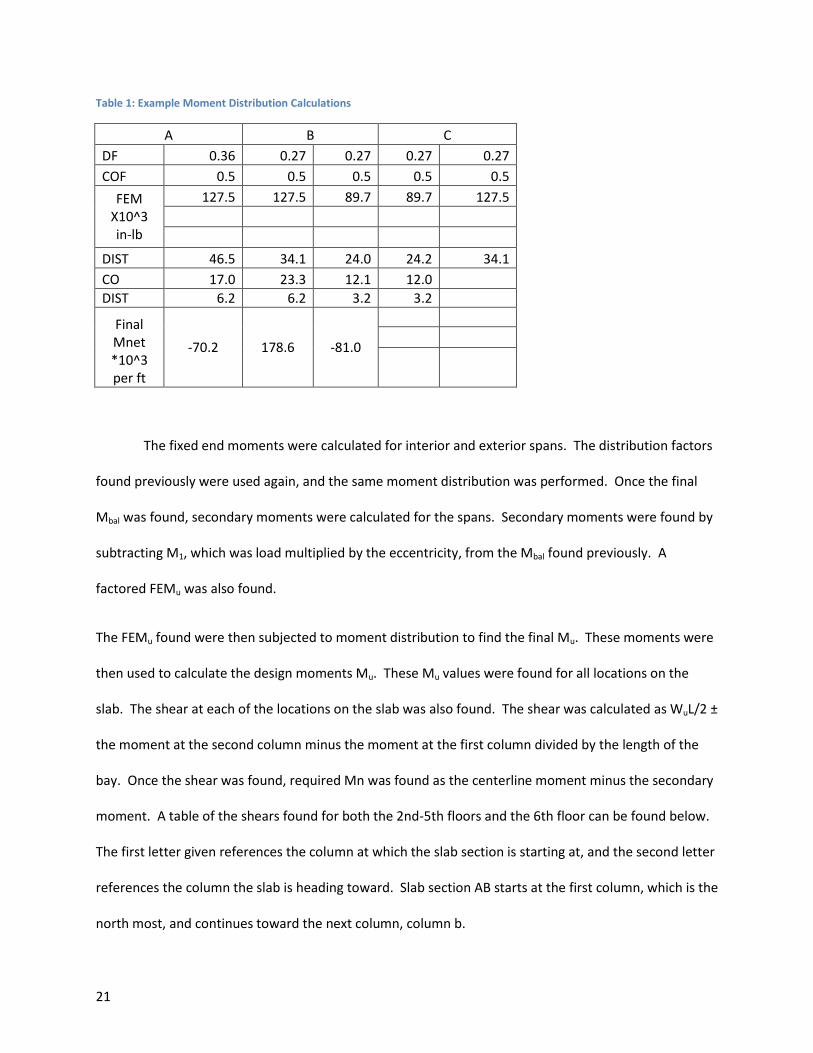
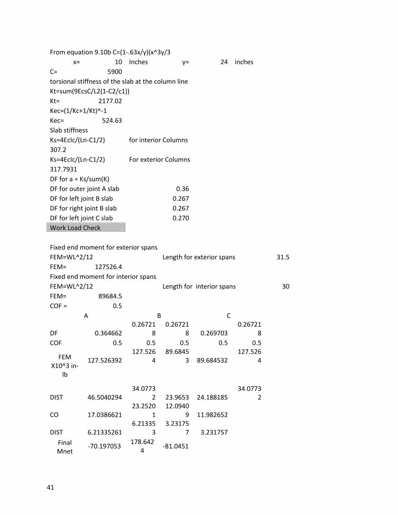
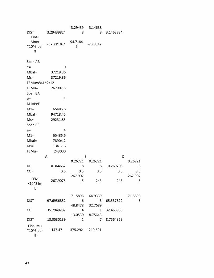
Table 1: Example Moment Distribution Calculations
A B C
DF 0.36 0.27 0.27 0.27 0.27
COF 0.5 0.5 0.5 0.5 0.5
FEM X10^3 in-lb
127.5 127.5 89.7 89.7 127.5
DIST 46.5 34.1 24.0 24.2 34.1
CO 17.0 23.3 12.1 12.0
DIST 6.2 6.2 3.2 3.2
Final Mnet *10^3 per ft
-70.2 178.6 -81.0
The fixed end moments were calculated for interior and exterior spans. The distribution factors
found previously were used again, and the same moment distribution was performed. Once the final
Mbal was found, secondary moments were calculated for the spans. Secondary moments were found by
subtracting M1, which was load multiplied by the eccentricity, from the Mbal found previously. A
factored FEMu was also found.
The FEMu found were then subjected to moment distribution to find the final Mu. These moments were
then used to calculate the design moments Mu. These Mu values were found for all locations on the
slab. The shear at each of the locations on the slab was also found. The shear was calculated as WuL/2 ±
the moment at the second column minus the moment at the first column divided by the length of the
bay. Once the shear was found, required Mn was found as the centerline moment minus the secondary
moment. A table of the shears found for both the 2nd-5th floors and the 6th floor can be found below.
The first letter given references the column at which the slab section is starting at, and the second letter
references the column the slab is heading toward. Slab section AB starts at the first column, which is the
north most, and continues toward the next column, column b.
22
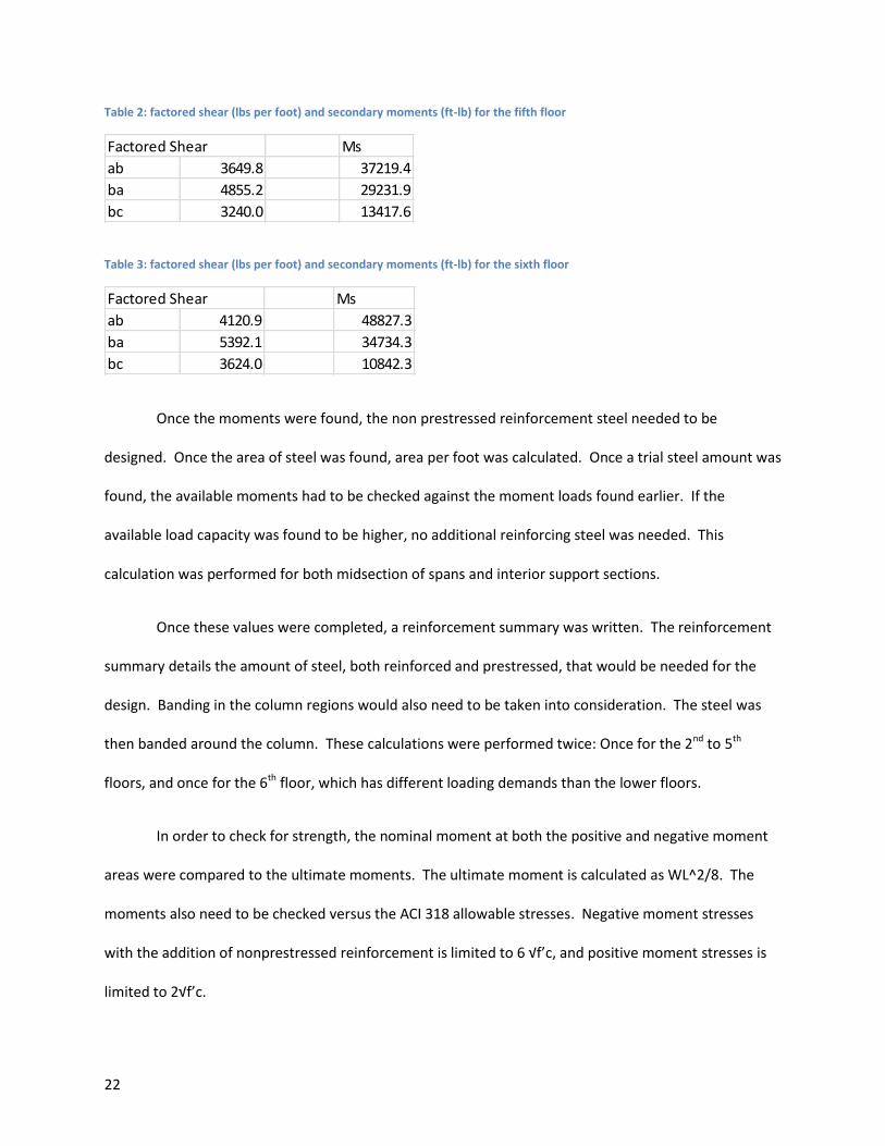
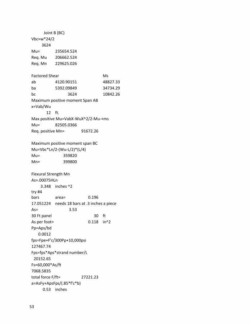
Table 2: factored shear (lbs per foot) and secondary moments (ft-lb) for the fifth floor
Table 3: factored shear (lbs per foot) and secondary moments (ft-lb) for the sixth floor
Once the moments were found, the non prestressed reinforcement steel needed to be
designed. Once the area of steel was found, area per foot was calculated. Once a trial steel amount was
found, the available moments had to be checked against the moment loads found earlier. If the
available load capacity was found to be higher, no additional reinforcing steel was needed. This
calculation was performed for both midsection of spans and interior support sections.
Once these values were completed, a reinforcement summary was written. The reinforcement
summary details the amount of steel, both reinforced and prestressed, that would be needed for the
design. Banding in the column regions would also need to be taken into consideration. The steel was
then banded around the column. These calculations were performed twice: Once for the 2nd to 5th
floors, and once for the 6th floor, which has different loading demands than the lower floors.
In order to check for strength, the nominal moment at both the positive and negative moment
areas were compared to the ultimate moments. The ultimate moment is calculated as WL^2/8. The
moments also need to be checked versus the ACI 318 allowable stresses. Negative moment stresses
with the addition of nonprestressed reinforcement is limited to 6 √f’c, and positive moment stresses is
limited to 2√f’c.
Factored Shear Ms
ab 3649.8 37219.4
ba 4855.2 29231.9
bc 3240.0 13417.6
Factored Shear Ms
ab 4120.9 48827.3
ba 5392.1 34734.3
bc 3624.0 10842.3
23
The flooring system also contains spandrel beams at the perimeter of the post tensioned slab.
These beams are reinforced concrete. The beams are 5,000 psi and 18 by 24 inch rectangular beams.
The first step in the beam design was to find the factored load and moment and shear demand.
Once the load and moment values were calculated, the capacity of the section was checked.
The maximum nominal moment is calculated first, and knowing bd^2, one can calculate rho and
determine the required steel.
Once the compression and tension steel is found, the available moment capacity is found. If the
moment capacity is higher than the moment found in the beginning of the design, no further check for
moment capacity is needed.
The design needed to be checked for shear capacity as well. The shear strength of the concrete
Vc is calculated and compared to the maximum shear Vu. If one half of the shear strength of the
concrete is less than the ultimate shear, shear steel is needed. Two number 4 stirrups were placed with
a spacing of 8 inches. Once the beam has been designed for shear and moment, deflection needs to be
checked. If the deflection is less than the limit set by ACI 318, the beam is sufficiently designed.

24
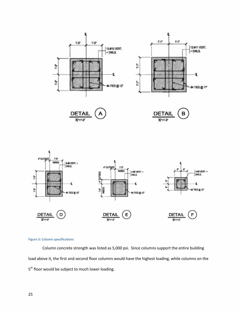
Columns
The columns were the next members to be reviewed. The columns used in this design were not
prestressed, but reinforced concrete. There were five different column designs used in this structure,
according to the design drawings provided. Only five were used for constructability reasons. For the
peer review, I checked three representative columns. These were one interior column, one column on
the corner of the slabs, and one located at the end of a slab in the middle of the wall, not at either
corner. These three different columns were sufficient to check the accuracy of the column design.
25
Figure 5: Column specifications
Column concrete strength was listed as 5,000 psi. Since columns support the entire building
load above it, the first and second floor columns would have the highest loading, while columns on the
5th floor would be subject to much lower loading.
26
The first step towards review was finding the tributary area and loading. This was done simply
by calculating the loads for each of the floors above the second, as well as the weight of the upper floor
columns as well. The tributary area was found to be 31.5 X 30 feet for interior columns. With the
loading found, the next step was to find the gross area of the columns, which was found using the
formula Ag=Pu/Φ*α*(.85f'c+pg (Fy-.85f'c).
The columns had a K value of 1.0. The story height was also found to be less than 12 times h, so
slenderness could be neglected. The area of steel was found next. The next steel that needed to be
found was the ties. There are two different types of tie used in column design: lateral ties and spiral
ties. For the columns in this design, lateral ties were used. The tie spacing cannot exceed the least
column dimension, 48 tie bar diameters or 16 longitudinal bar diameters, whichever value is lowest.
There is also moment in the column, which means there will be shear that will also act on the stirrups.
Once the column size and steel are designed, P-M diagrams needed to be created. P-M
diagrams are created using 5 points on the load vs. moment graph. P-M diagrams also display the
eccentricity at these points.
The first point of an interaction diagram is found when you set Fs equal to Fy. єU is assumed to
be equal to .003 in this case. Єy is found as the product of Fu/Es, or the ultimate strength divided by the
modulus of elasticity for the steel. The depth, d, is found as the length of a side of the column minus the
cover minus the diameter of the steel tie and finally subtracting half the diameter of the reinforcing bar.
C can be found once these values have been found. Once the value of Cb, or C balanced, has been
found, C is found. C is equal to .85f'c*a*h. Cb is the distance in the compression block where balanced
failure happens. The nominal load Pn and nominal moment Mn are found after and plotted on the
interaction diagram. The eccentricity is also marked on the interaction diagram, typically as a dashed
line leading to the point.

27
The next point on the diagram is found in a very similar fashion. The only difference is a smaller
value is chosen in place of Cb. This means that the value is in the tension failure area of the interaction
diagram. The same formulas are followed after this, and a new point can be added to the interaction
diagram.
The third point on the diagram is found through a similar procedure. This time around, a C value higher
than Cb was chosen, to see how the column reacted to compression failure. Since the column is made of
concrete, it can be assumed that the values associated with compression failure would be higher than
tension failure.
The fourth point is found when C is infinite. When C is infinite, the eccentricity will be 0. Under
this condition, there will be no moment, only a load. This point is found on the Y axis of interaction
diagrams. The final point is a pure moment load.
When an edge or side column is reviewed as opposed to an interior column, the tributary area
will be lower. This means that the load becomes lower. This is counterbalanced however, with a much
higher eccentricity. Another factor to take into account is constructability. It is much easier for a
construction crew to create the same size column multiple times, instead of many different size
columns. This helps account for the uniform nature of the columns found in this design.
28
Shear Walls
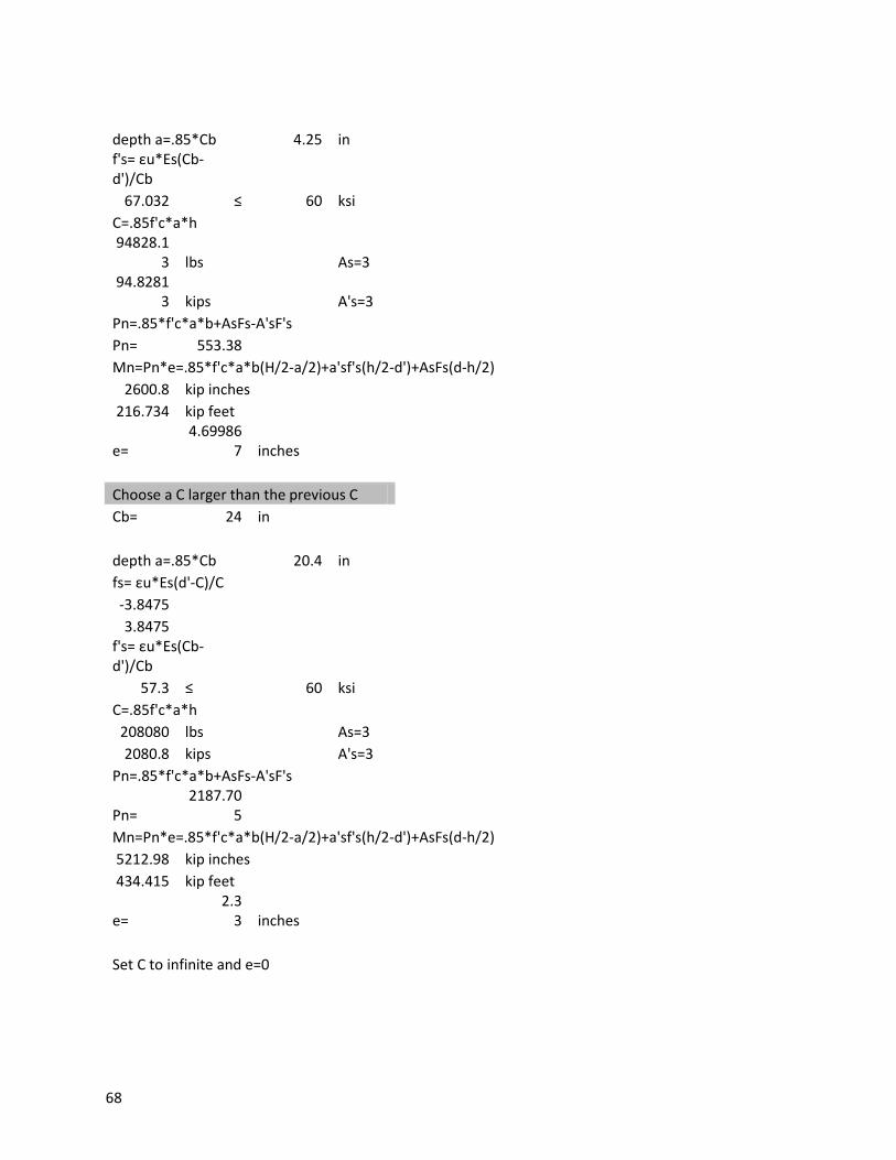
A shear wall is a member of a structure that is designed for the lateral load demands on the structure.
These loads are typically wind and earthquakes. Similar to the columns in this structure, the shear walls
are made of reinforced and not prestressed concrete. These walls work as a large cantilever beam
jutting from the base of the building. This structure has three shear walls, one near the stairs, one near
the elevator, and one in the north east corner of the structure. The review of shear walls was completed
while using a journal article titled "Time Saving Design Aids for Reinforced Concrete.4"
Because shear walls are subject to more diverse loading, a new load combination was needed. Once the
new load combination was found, the loads due to wind and earthquake needed to be calculated. The
shear walls were a foot thick and 5,000 psi concrete. A new floor starts every 10.5 feet.
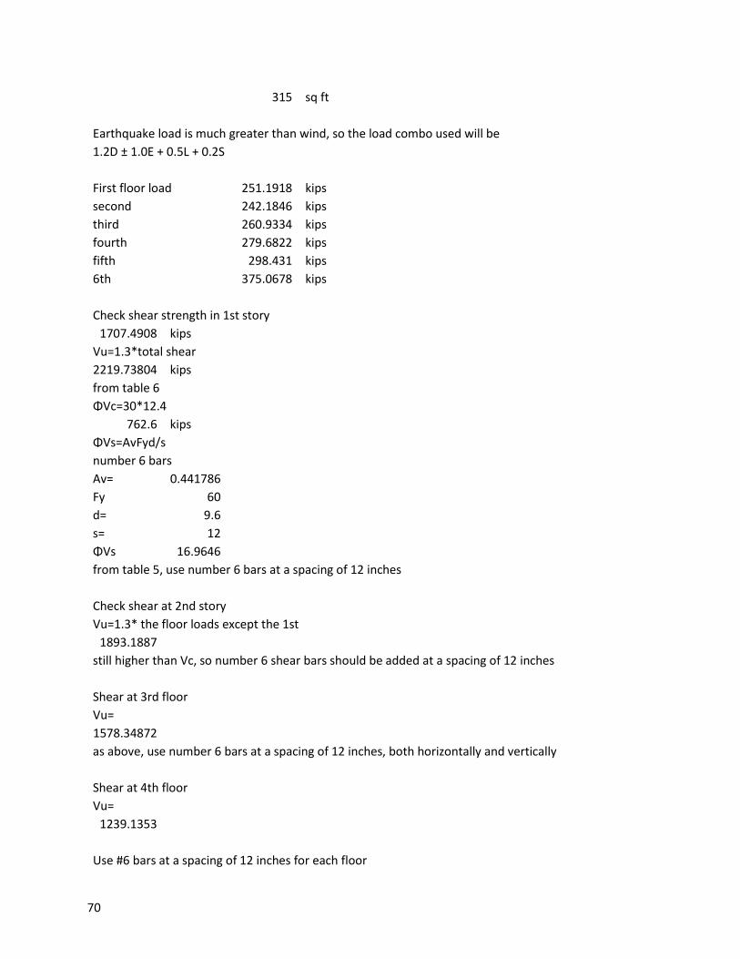
The shear load on the shear walls was first checked at the first floor. This floor was subject to the
largest loading and therefore would have the highest demand for a shear wall. First, the total shear was
calculated. Then the nominal shear, фVc was found. Because the ultimate shear is higher than the
nominal shear strength of the concrete, horizontal reinforcing steel was needed. The amount of
required horizontal shear reinforcement is decided using table 6.5 from the guide referenced above.
The required vertical reinforcement is then found. For the first floor, #6 bars at a spacing of 12 inches
were calculated.
4 Fanella, David A. "Time Saving Design Aids for Reinforced Concrete." Structural Engineer (2001): 42-47. Web.
<https://engineering.purdue.edu/~frosch/CE576/Time%20Saving%20Design%20Tips/Time%20Saving-
Columns&Walls.pdf>.
29
The second floor calculations were completed using the same methodology. First the horizontal shear
reinforcement was found, followed by the vertical. The upper level floors were apparently given the
same bar spacing as well, for the sake of constructability and simplicity. Though this simplifies the
construction, it is a more costly option.
Shear walls resist overturning moment as well as shear forces. The overturning moment
essentially is the force that attempts to destabilize the structure by lifting and overturning it. Shear
walls need to be designed to withstand the moment that loading offers without overturning. In order to
design the shear walls for overturning, moment load and axial load are calculated for each floor. The
moment strength was then checked based on the required vertical shear reinforcement. The area of the
steel, ω, α and c/lw were found in order to calculate the available moment. Once the available moment,
фMn was found, it was compared to the ultimate moment. If the available moment was larger than the
ultimate, no more reinforcement was needed for moment. This process was repeated for each floor.
30
Structural Steel Flooring System
In order to satisfy the capstone design requirement, the floor framing were redesigned as
structural steel instead of post tensioned concrete. Structural steel offers advantages over concrete.
The steel layout chosen is a beam and girder system with a metal deck and concrete poured onto the
decking. The decking provides a mold for the concrete, and shear studs are welded to the deck to
facilitate composite action. The beams and girders were both wide flanged, also referred to as W shape
beams.
The steel scheme started like its concrete counterpart, with loads being calculated. Due to the
smaller depth of the concrete, the dead load is much less for the steel scheme. The Scheme consists of
30 foot beams and 31.5 foot girders on the outer spans and 30 foot girders in the inner span. The
beams were spaced at 10 foot intervals.
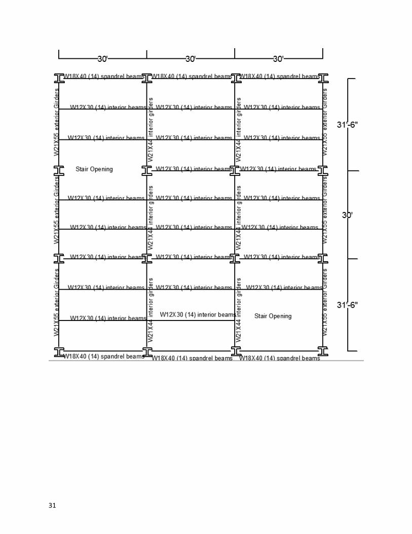
31
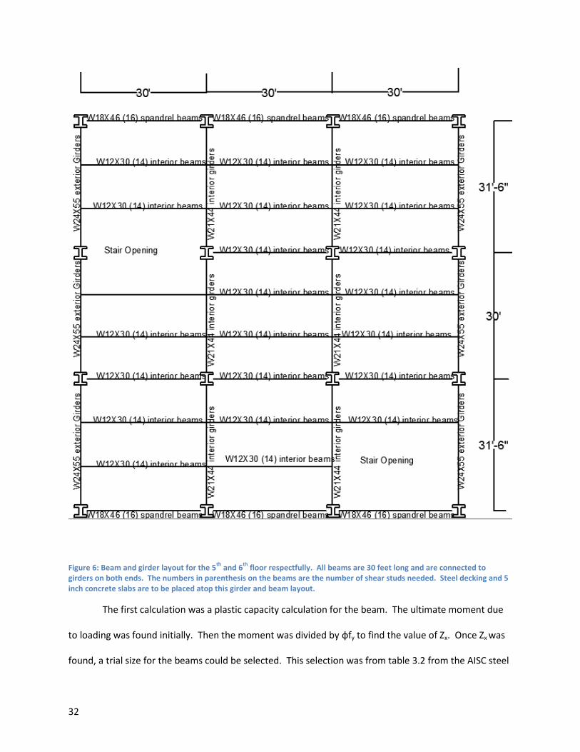
32
Figure 6: Beam and girder layout for the 5th
and 6th
floor respectfully. All beams are 30 feet long and are connected to girders on both ends. The numbers in parenthesis on the beams are the number of shear studs needed. Steel decking and 5 inch concrete slabs are to be placed atop this girder and beam layout.
The first calculation was a plastic capacity calculation for the beam. The ultimate moment due
to loading was found initially. Then the moment was divided by фfy to find the value of Zx. Once Zx was
found, a trial size for the beams could be selected. This selection was from table 3.2 from the AISC steel
33
construction manual. Once the trial beam size was found, a new dead load was calculated taking self-
weight of the beam into account. The beam choice was checked by comparing the new allowable
moment to the new ultimate moment due to loading. This process needed to be repeated until the
allowable moment was higher than the moment due to loading.
Once a beam size is selected, it needs to be checked against deflection. The deflection of a
beam when only dead load is considered has to be below length over 360, whichever is smaller. This
ensures the flooring won’t be so slanted it causes issues. In order to calculate deflection, the moment of
inertia Ix needed to be obtained from table 3.3 of the AISC manual. The beam chosen for the design
scheme was found to be sufficient, but if it was not a new beam would be selected for a higher moment
of inertia from table 3.3. After that deflection case was tested, a second case involving full dead load
and half live load was tested. Since this had a higher load, the allowable deflections were higher as well.
The new limits used were length divided by 240 or 1.5 inches, which ever was smaller.
After the beam was checked for deflection limit state, it was time to find a girder size. The
method for finding a girder size is the same as for beams. The girders will naturally be larger than
beams, because girders have to support the flooring and the beams, as well as self-weight. The final
beam and girder sizings for the 6th and 5th floors can be found in the table below.
Once the girder and beam sizes were established, the decking and concrete flooring were
designed. The depth of the concrete slab was designed as 5 inches. The concrete was 4000 psi
concrete. The shear studs along the decking were ¾ inch diameter studs.
A composite beam was calculated next. In order to find a new beam, the value of Be was found.
Be is twice the value of the lesser of length over 8 and beam spacing over two. In this case Be was found
to be 90 inches. The next value found was Y2. Y2 is the thickness of the concrete minus a/2. With these
values, a new beam can be chosen from table 3-19 of the AISC steel manual. Once a new beam is
34
chosen, a and Y2 need to be recalculated. The shear capacity ∑Qn was then found for the beam, and
with the shear capacity the moment capacity could be calculated. When compared to the moment load,
it was found to be inadequate, so a new beam had to be chosen. The new beam was chosen for its ∑Qn
value, so it was sufficient.
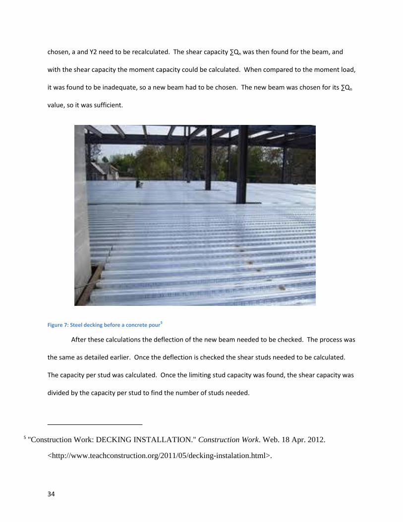
Figure 7: Steel decking before a concrete pour5
After these calculations the deflection of the new beam needed to be checked. The process was
the same as detailed earlier. Once the deflection is checked the shear studs needed to be calculated.
The capacity per stud was calculated. Once the limiting stud capacity was found, the shear capacity was
divided by the capacity per stud to find the number of studs needed.
5 "Construction Work: DECKING INSTALLATION." Construction Work. Web. 18 Apr. 2012.
<http://www.teachconstruction.org/2011/05/decking-instalation.html>.
35
The design needed to be checked for unshored construction loads next. This check makes sure
the design won’t be too weak to support the forces construction will put on it. The loads taken into
account were the weight of wet concrete, and the beam weight and construction live load. The
construction live load was assumed to be roughly 20 psf. A load and moment were calculated for these
weights, and they were tested against the allowable moment for the beam found in table 3.2.
Deflection during unshored construction was also calculated.
The next step in the process was to design for full composite. Composite is the term for the concrete
slab and steel decking and beams working as one member. The principles behind can be compared to
the principles behind the positioning of prestressing tendons. The steel is located on the bottom of the
slab to handle tension forces, while the concrete handles compression forces. Full composite is typically
less advantageous then its partial counterpart, as it is more cost effective than full composite, due to
less materials and less welding. Partial composite is similar to full composite, but uses less shear studs
to accomplish the same uses. Both full and partial composite is more cost effective than a non-
composite design.
The first step in full composite calculations is calculating a new shear capacity ∑Qn. The capacity
per shear stud remains the same, so the number of studs does not change dramatically. In order to
check if shear composite is possible, the value a needed to be calculated again. As long as “a “ was not
larger than the thickness of the concrete, full composite was possible.
The next step in the design was to check how much composite capacity was needed. This is
checked by using table 3-19. This table shows the moment values at different levels of the partial
neutral axis. The further down the steel the partial neutral axis is, the more steel is in tension. Once the
partial neutral axis was located, a deflection check was performed. Once the deflection was found to be
sufficient, the number of shear studs needed was calculated. The capacity per stud remained the same,
36
but the shear capacity ∑Qn was dramatically lower, allowing for fewer shear studs to be needed. The
shear studs for the 6th floor, for example, went from 21 to 7 studs. Once the shear studs were found,
the beam design was completed. The girders were designed for the decking slab next. The girders were
designed as described previously.
Once the interior beams and girders were designed, spandrel beams and girders were designed.
The spandrel beams and girders were designed separately, because they have higher loading due to the
shear walls. The beams and girders were designed in the same way as the interior beams and girders,
but they had half the tributary area and a much higher dead load. The final floor design layouts can be
found in figure 6 above.
37
Results and Conclusions
The Massachusetts College of Pharmacy and Health Sciences peer review reviews a six story post
tensioned concrete building currently being erected in Worcester, Massachusetts. Souza, True and
Partners is the structural engineering firm responsible for the design of the building. The building was
designed for office space, lecture halls, and laboratories. This post tensioned structure was reviewed for
slab, column, and shear wall design. The design checked for both gravity and lateral loading. The loads
were all supplied by the design plans. All designs were performed according to Load and resistance
factor design, as well as the American Concrete Institute manual ACI 318 08, and American institute of
steel construction CAPS manual.
The floor slabs were the first aspects reviewed. The 2nd through 5th floor slabs were uniform,
and exposed to the same loading. The 6th floor had a higher live load and the first floor had higher
loading as well. Due to this uniform loading, only the 6th and 5th floor slabs were reviewed. The slabs
were found to be satisfactorily designed, and adequately resistant to both shear and moment.
The next aspect reviewed was the columns. These columns were comprised of reinforced
concrete, as opposed to the post tensioned concrete used in other aspects of the building. The building
only had 5 different configurations of columns, and only three were used frequently. One column type
was used for interior columns, one for corner columns, and one for center exterior columns. The
difference in columns can be attributed to a difference in the loading and tributary area. Though
columns on the third floor had higher loads than columns on the fourth floor, the same sizes were used.
This was mainly for ease of construction. Interaction diagrams were created for the columns.
The lateral loading for the building was handled by shear walls. These shear walls are effectively
large cantilever beams, that take wind and earthquake loads with minimum displacement. These shear
walls supply the rigidity for the structure.
38
An alternate design for the floor slabs using structural steel beams and girders was completed as
well. The floor deck itself was a metal decking with a 5 inch thick concrete slab. The floor slab was
checked for unshored construction, as well as full and partial composite action. The slab design was
checked for deflection as well. The dead loading for this scheme was much lower than the post
tensioned slab. This is due to the high weight of concrete as opposed to steel.
The superstructure peer review of MCPHS was a culmination of the design courses taken over
the past few years. The building materials used included post tensioned concrete, reinforced concrete,
and steel design. All aspects that were reviewed were found to be satisfactory. In some cases, such as
the columns in the upper levels, the building is over designed for ease of construction and repeatability.
Though not all aspects were checked, a sufficient amount of the design was investigated to assume that
the engineer of record was competent and correct in his design process.
39
Appendix
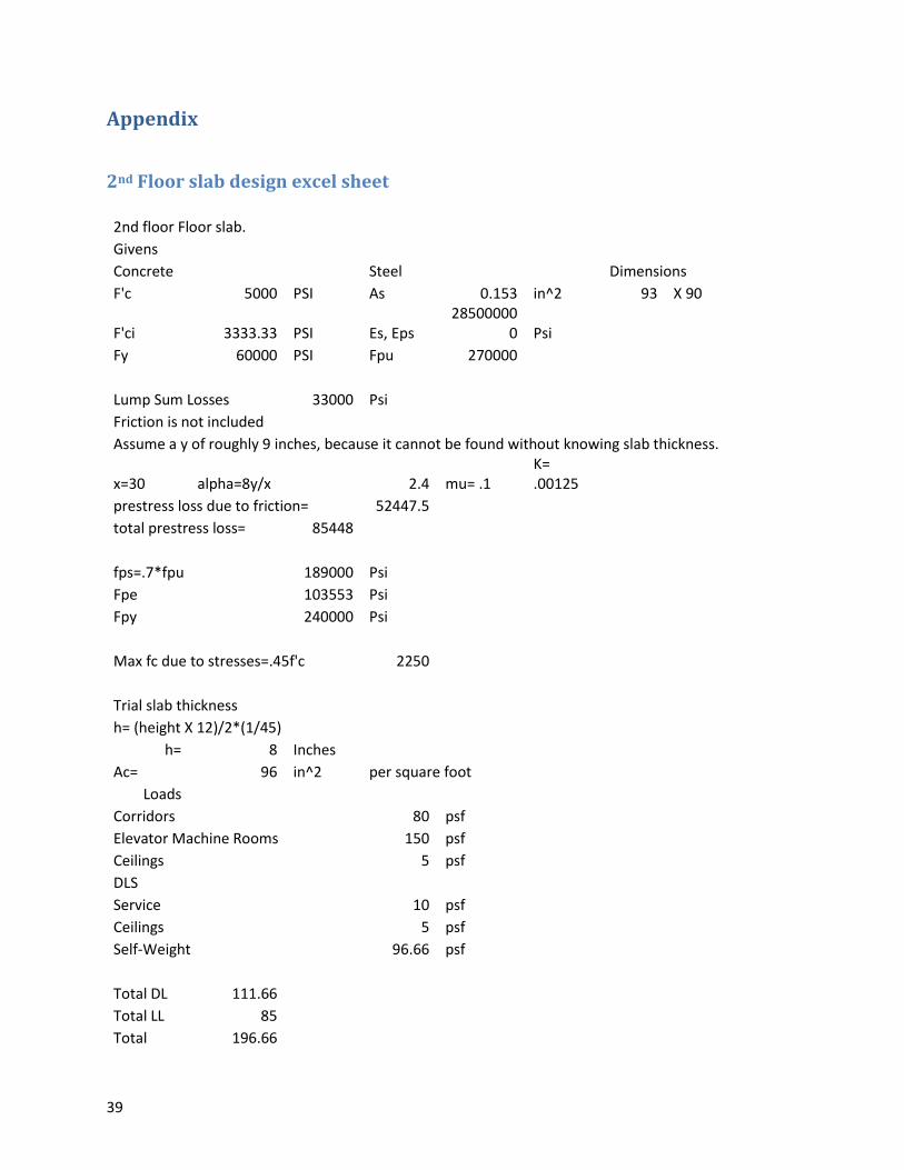
2nd Floor slab design excel sheet
2nd floor Floor slab. Givens
Concrete
Steel
Dimensions
F'c 5000 PSI As 0.153 in^2 93 X 90
F'ci 3333.33 PSI Es, Eps 28500000
0 Psi Fy 60000 PSI Fpu 270000
Lump Sum Losses 33000 Psi Friction is not included
Assume a y of roughly 9 inches, because it cannot be found without knowing slab thickness.
x=30 alpha=8y/x
2.4 mu= .1 K= .00125
prestress loss due to friction= 52447.5 total prestress loss= 85448
fps=.7*fpu 189000 Psi Fpe
103553 Psi
Fpy
240000 Psi
Max fc due to stresses=.45f'c 2250
Trial slab thickness h= (height X 12)/2*(1/45)
h= 8 Inches Ac= 96 in^2 per square foot
Loads Corridors
80 psf Elevator Machine Rooms 150 psf Ceilings
5 psf
DLS Service
10 psf Ceilings
5 psf
Self-Weight
96.66 psf
Total DL 111.66 Total LL 85 Total 196.66
40
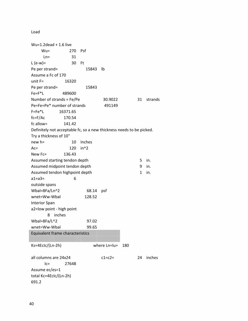
Load
Wu=1.2dead + 1.6 live Wu= 270 Psf
Ln= 31 L (e-w)= 30 Ft
Pe per strand= 15843 lb Assume a Fc of 170
unit F= 16320 Pe per strand= 15843
Fe=F*L 489600 Number of strands = Fe/Pe 30.9022 31 strands
Pe=Fe=Pe* number of strands 491149 F=Fe*L 16371.65
fc=F/Ac 170.54 fc allow= 141.42 Definitely not acceptable fc, so a new thickness needs to be picked.
Try a thickness of 10'' new h= 10 Inches
Ac= 120 in^2 New Fc= 136.43
Assumed starting tendon depth
5 in. Assumed midpoint tendon depth
9 in.
Assumed tendon highpoint depth 1 in. a1=a3= 6
outside spans Wbal=8Fa/Ln^2 68.14 psf
wnet=Ww-Wbal 128.52 Interior Span
a2=low point - high point 8 inches
Wbal=8Fa/L^2 97.02 wnet=Ww-Wbal 99.65 Equivalent frame characteristics
Ks=4EcIc/(Ln-2h) where Ln=lu= 180
all columns are 24x24
c1=c2= 24 inches Ic= 27648
Assume ec/es=1 total Kc=4EcIc/(Ln-2h) 691.2
41
From equation 9.10b C=(1-.63x/y)(x^3y/3 x= 10 Inches y= 24 inches
C= 5900 torsional stiffness of the slab at the column line
Kt=sum(9EcsC/L2(1-C2/c1)) Kt= 2177.02
Kec=(1/Kc+1/Kt)^-1 Kec= 524.63 Slab stiffness Ks=4EcIc/(Ln-C1/2) for interior Columns
307.2 Ks=4EcIc/(Ln-C1/2) For exterior Columns
317.7931 DF for a = Ks/sum(K)
DF for outer joint A slab 0.36 DF for left joint B slab
0.267
DF for right joint B slab
0.267 DF for left joint C slab
0.270
Work Load Check
Fixed end moment for exterior spans FEM=WL^2/12
Length for exterior spans 31.5
FEM= 127526.4 Fixed end moment for interior spans
FEM=WL^2/12
Length for interior spans 30 FEM= 89684.5
COF = 0.5 A B C
DF 0.364662
0.267218
0.267218 0.269703
0.267218
COF 0.5 0.5 0.5 0.5 0.5
FEM X10^3 in-
lb
127.526392 127.526
4 89.6845
3 89.684532 127.526
4
DIST 46.5040294
34.07732 23.9653 24.188185
34.07732
CO 17.0386621
23.25201
12.09409 11.982652
DIST 6.21335261
6.213353
3.231757 3.231757
Final Mnet
-70.197053 178.642
4 -81.0451
42
*10^3 per ft
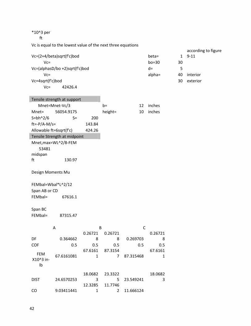
Vc is equal to the lowest value of the next three equations
Vc=(2+4/beta)sqrt(f'c)bod
beta= 1 according to figure 9-11
Vc=
bo=30 30 Vc=(alphasD/bo +2)sqrt(f'c)bod
d= 5
Vc=
alpha= 40 interior
Vc=4sqrt(f'c)bod
30 exterior
Vc= 42426.4
Tensile strength at support Mnet=Mnet-Vc/3
b= 12 inches
Mnet= 56054.9175
height= 10 inches S=bh^2/6 S= 200
ft=-P/A-M/s= 143.84 Allowable ft=6sqrt(f'c) 424.26 Tensile Strength at midpoint Mnet,max=WL^2/8-FEM 53481
midspan ft 130.97
Design Moments Mu
FEMbal=Wbal*L^2/12 Span AB or CD FEMbal= 67616.1
Span BC FEMbal= 87315.47
A B C
DF 0.364662 0.26721
8 0.26721
8 0.269703 0.26721
8 COF 0.5 0.5 0.5 0.5 0.5
FEM X10^3 in-
lb
67.6161081 67.6161
1 87.3154
7 87.315468 67.6161
1
DIST 24.6570253
18.06823
23.33225 23.549241
18.06823
CO 9.03411441
12.32851
11.77462 11.666124
43
DIST 3.29439824 3.29439
8 3.14638
8 3.1463884 Final
Mnet *10^3 per
ft
-37.219367 94.7184
5 -78.9042
Span AB e= 0
Mbal= 37219.36 Ms= 37219.36 FEMu=WuL^2/12 FEMu= 267907.5 Span BA
e= 4 M1=PeE
M1= 65486.6 Mbal= 94718.45 Ms= 29231.85 Span BC
e= 4 M1= 65486.6 Mbal= 78904.2 Ms= 13417.6 FEMu= 243000 A B C
DF 0.364662
0.267218
0.267218 0.269703
0.267218
COF 0.5 0.5 0.5 0.5 0.5
FEM X10^3 in-
lb
267.9075 267.907
5 243 243 267.907
5
DIST 97.6956852
71.58966
64.93393 65.537822
71.58966
CO 35.7948287
48.84784
32.76891 32.466965
DIST 13.0530139
13.05301
8.756437 8.7564369
Final Mu *10^3 per
ft
-147.47 375.292 -219.591
44
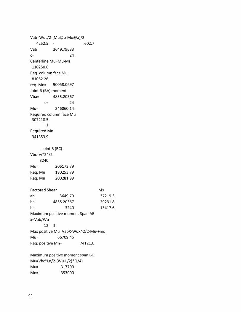
Vab=WuL/2-(Mu@b-Mu@a)/2 4252.5 - 602.7 Vab= 3649.79633
c= 24 Centerline Mu=Mu-Ms 110250.6
Req. column face Mu
81052.26
req. Mn= 90058.0697
Joint B (BA) moment Vba= 4855.20367 c= 24 Mu= 346060.14 Required column face Mu
307218.51
Required Mn 341353.9
Joint B (BC) Vbc=w*24/2 3240
Mu= 206173.79 Req. Mu 180253.79 Req. Mn 200281.99
Factored Shear
Ms ab 3649.79
37219.3
ba 4855.20367
29231.8 bc 3240
13417.6
Maximum positive moment Span AB x=Vab/Wu
12 ft. Max positive Mu=VabX-WuX^2/2-Mu-+ms
Mu= 66709.45 Req. positive Mn= 74121.6
Maximum positive moment span BC Mu=Vbc*Ln/2-(Wu-L/2)*(L/4)
Mu= 317700 Mn= 353000
45
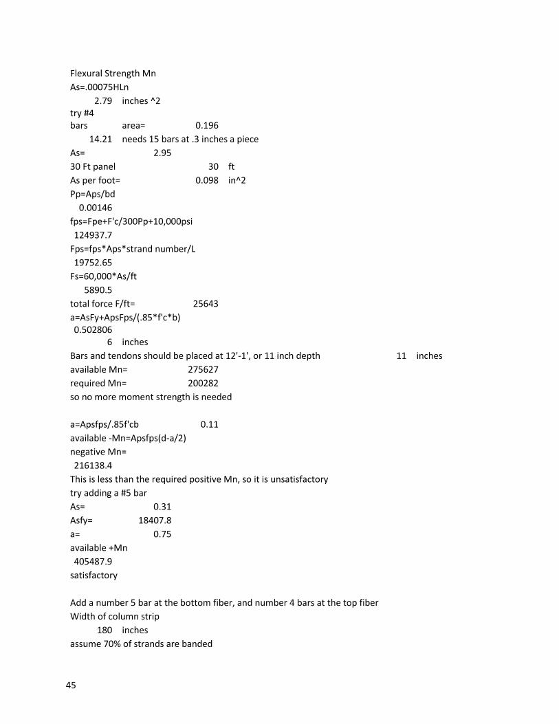
Flexural Strength Mn As=.00075HLn 2.79 inches ^2 try #4
bars area= 0.196 14.21 needs 15 bars at .3 inches a piece
As= 2.95 30 Ft panel 30 ft
As per foot= 0.098 in^2 Pp=Aps/bd
0.00146 fps=Fpe+F'c/300Pp+10,000psi
124937.7 Fps=fps*Aps*strand number/L
19752.65 Fs=60,000*As/ft
5890.5 total force F/ft= 25643
a=AsFy+ApsFps/(.85*f'c*b) 0.502806
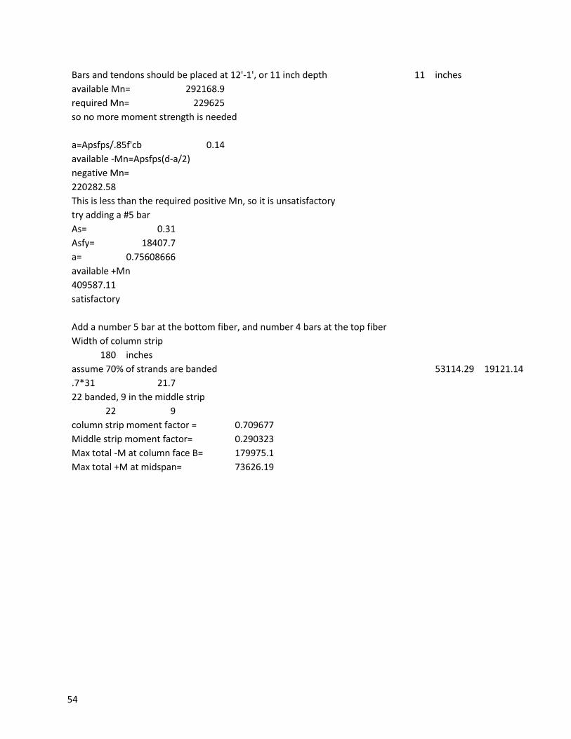
6 inches Bars and tendons should be placed at 12'-1', or 11 inch depth 11 inches
available Mn= 275627 required Mn= 200282 so no more moment strength is needed
a=Apsfps/.85f'cb 0.11 available -Mn=Apsfps(d-a/2) negative Mn=
216138.4 This is less than the required positive Mn, so it is unsatisfactory
try adding a #5 bar As= 0.31 Asfy= 18407.8 a= 0.75 available +Mn 405487.9
satisfactory
Add a number 5 bar at the bottom fiber, and number 4 bars at the top fiber Width of column strip
180 inches assume 70% of strands are banded

46
.7*31 21.7 22 banded, 9 in the middle strip
22 9 column strip moment factor = 0.71
Middle strip moment factor= 0.29 Max total -M at column face B= 178642

47
Max total +M at midspan= 73080.9
48
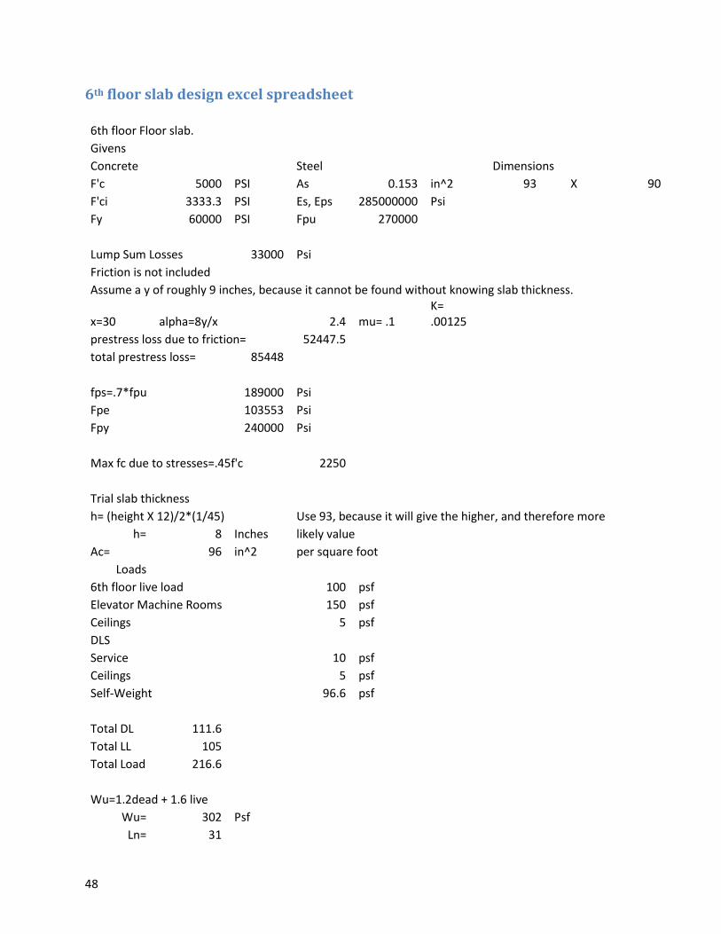
6th floor slab design excel spreadsheet
6th floor Floor slab. Givens
Concrete
Steel
Dimensions F'c 5000 PSI As 0.153 in^2 93 X 90
F'ci 3333.3 PSI Es, Eps 285000000 Psi Fy 60000 PSI Fpu 270000
Lump Sum Losses 33000 Psi Friction is not included
Assume a y of roughly 9 inches, because it cannot be found without knowing slab thickness.
x=30 alpha=8y/x
2.4 mu= .1 K= .00125
prestress loss due to friction= 52447.5 total prestress loss= 85448
fps=.7*fpu 189000 Psi Fpe
103553 Psi
Fpy
240000 Psi
Max fc due to stresses=.45f'c 2250
Trial slab thickness h= (height X 12)/2*(1/45) Use 93, because it will give the higher, and therefore more
h= 8 Inches likely value Ac= 96 in^2 per square foot Loads
6th floor live load
100 psf Elevator Machine Rooms 150 psf Ceilings
5 psf
DLS Service
10 psf Ceilings
5 psf
Self-Weight
96.6 psf
Total DL 111.6 Total LL 105 Total Load 216.6
Wu=1.2dead + 1.6 live Wu= 302 Psf
Ln= 31
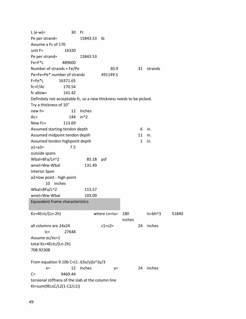
49
L (e-w)= 30 Ft Pe per strand= 15843.53 lb
Assume a Fc of 170 unit F= 16320 Pe per strand= 15843.53
Fe=F*L 489600 Number of strands = Fe/Pe 30.9 31 strands
Pe=Fe=Pe* number of strands 491149.5 F=Fe*L 16371.65
fc=F/Ac 170.54 fc allow= 141.42 Definitely not acceptable fc, so a new thickness needs to be picked.
Try a thickness of 10'' new h= 12 Inches
Ac= 144 in^2 New Fc= 113.69
Assumed starting tendon depth
6 in. Assumed midpoint tendon depth
11 in.
Assumed tendon highpoint depth 1 in. a1=a3= 7.5
outside spans Wbal=8Fa/Ln^2 85.18 psf
wnet=Ww-Wbal 131.49 Interior Span
a2=low point - high point 10 inches
Wbal=8Fa/L^2 113.57 wnet=Ww-Wbal 103.09 Equivalent frame characteristics
Ks=4EcIc/(Ln-2h) where Ln=lu= 180 Is=bh^3 51840
inches
all columns are 24x24
c1=c2= 24 inches Ic= 27648
Assume ec/es=1 total Kc=4EcIc/(Ln-2h) 708.92308
From equation 9.10b C=(1-.63x/y)(x^3y/3 x= 12 Inches y= 24 inches
C= 9469.44 torsional stiffness of the slab at the column line
Kt=sum(9EcsC/L2(1-C2/c1))
50
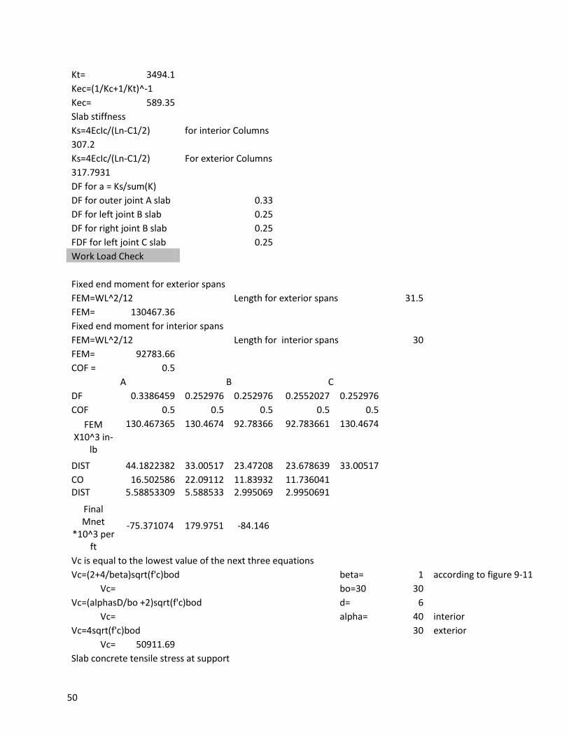
Kt= 3494.1 Kec=(1/Kc+1/Kt)^-1 Kec= 589.35 Slab stiffness Ks=4EcIc/(Ln-C1/2) for interior Columns
307.2 Ks=4EcIc/(Ln-C1/2) For exterior Columns
317.7931 DF for a = Ks/sum(K)
DF for outer joint A slab 0.33 DF for left joint B slab
0.25
DF for right joint B slab
0.25 FDF for left joint C slab
0.25
Work Load Check
Fixed end moment for exterior spans FEM=WL^2/12
Length for exterior spans 31.5
FEM= 130467.36 Fixed end moment for interior spans
FEM=WL^2/12
Length for interior spans 30 FEM= 92783.66
COF = 0.5 A B C
DF 0.3386459 0.252976 0.252976 0.2552027 0.252976 COF 0.5 0.5 0.5 0.5 0.5 FEM
X10^3 in-lb
130.467365 130.4674 92.78366 92.783661 130.4674
DIST 44.1822382 33.00517 23.47208 23.678639 33.00517 CO 16.502586 22.09112 11.83932 11.736041
DIST 5.58853309 5.588533 2.995069 2.9950691 Final
Mnet *10^3 per
ft
-75.371074 179.9751 -84.146
Vc is equal to the lowest value of the next three equations Vc=(2+4/beta)sqrt(f'c)bod
beta= 1 according to figure 9-11
Vc=
bo=30 30 Vc=(alphasD/bo +2)sqrt(f'c)bod
d= 6
Vc=
alpha= 40 interior Vc=4sqrt(f'c)bod
30 exterior
Vc= 50911.69 Slab concrete tensile stress at support
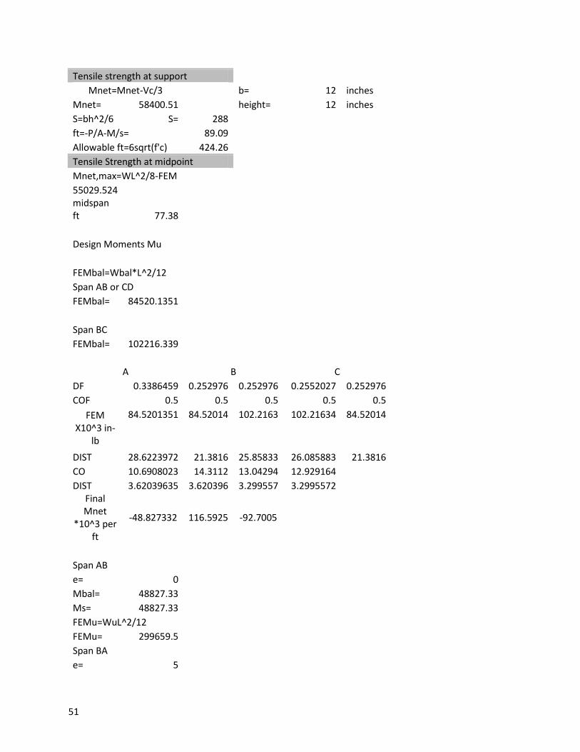
51
Tensile strength at support Mnet=Mnet-Vc/3
b= 12 inches
Mnet= 58400.51
height= 12 inches S=bh^2/6 S= 288
ft=-P/A-M/s= 89.09 Allowable ft=6sqrt(f'c) 424.26 Tensile Strength at midpoint Mnet,max=WL^2/8-FEM 55029.524
midspan ft 77.38
Design Moments Mu
FEMbal=Wbal*L^2/12 Span AB or CD FEMbal= 84520.1351
Span BC FEMbal= 102216.339
A B C DF 0.3386459 0.252976 0.252976 0.2552027 0.252976 COF 0.5 0.5 0.5 0.5 0.5 FEM
X10^3 in-lb
84.5201351 84.52014 102.2163 102.21634 84.52014
DIST 28.6223972 21.3816 25.85833 26.085883 21.3816 CO 10.6908023 14.3112 13.04294 12.929164
DIST 3.62039635 3.620396 3.299557 3.2995572 Final
Mnet *10^3 per
ft
-48.827332 116.5925 -92.7005
Span AB e= 0
Mbal= 48827.33 Ms= 48827.33 FEMu=WuL^2/12 FEMu= 299659.5 Span BA
e= 5
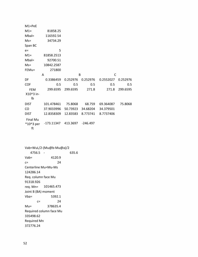
52
M1=PeE M1= 81858.25
Mbal= 116592.54 Ms= 34734.29 Span BC
e= 5 M1= 81858.2513 Mbal= 92700.51 Ms= 10842.2587 FEMu= 271800 A B C
DF 0.3386459 0.252976 0.252976 0.2552027 0.252976 COF 0.5 0.5 0.5 0.5 0.5 FEM
X10^3 in-lb
299.6595 299.6595 271.8 271.8 299.6595
DIST 101.478461 75.8068 68.759 69.364087 75.8068 CO 37.9033996 50.73923 34.68204 34.379501
DIST 12.8358309 12.83583 8.773741 8.7737406 Final Mu
*10^3 per ft
-173.11347 413.3697 -246.497
Vab=WuL/2-(Mu@b-Mu@a)/2 4756.5 - 635.6 Vab= 4120.9
c= 24 Centerline Mu=Mu-Ms 124286.14
Req. column face Mu
91318.926
req. Mn= 101465.473
Joint B (BA) moment Vba= 5392.1 c= 24 Mu= 378635.4 Required column face Mu
335498.62 Required Mn
372776.24
53
Joint B (BC) Vbc=w*24/2 3624
Mu= 235654.524 Req. Mu 206662.524 Req. Mn 229625.026
Factored Shear
Ms ab 4120.90151
48827.33
ba 5392.09849
34734.29 bc 3624
10842.26
Maximum positive moment Span AB x=Vab/Wu
12 ft. Max positive Mu=VabX-WuX^2/2-Mu-+ms
Mu= 82505.0366 Req. positive Mn= 91672.26
Maximum positive moment span BC Mu=Vbc*Ln/2-(Wu-L/2)*(L/4)
Mu= 359820 Mn= 399800
Flexural Strength Mn As=.00075HLn 3.348 inches ^2 try #4
bars area= 0.196 17.051224 needs 18 bars at .3 inches a piece
As= 3.53 30 Ft panel 30 ft
As per foot= 0.118 in^2 Pp=Aps/bd
0.0012 fps=Fpe+F'c/300Pp+10,000psi
127467.74 Fps=fps*Aps*strand number/L
20152.65 Fs=60,000*As/ft
7068.5835 total force F/ft= 27221.23
a=AsFy+ApsFps/(.85*f'c*b) 0.53 inches
54
Bars and tendons should be placed at 12'-1', or 11 inch depth 11 inches available Mn= 292168.9
required Mn= 229625 so no more moment strength is needed
a=Apsfps/.85f'cb 0.14 available -Mn=Apsfps(d-a/2) negative Mn=
220282.58 This is less than the required positive Mn, so it is unsatisfactory
try adding a #5 bar As= 0.31 Asfy= 18407.7 a= 0.75608666 available +Mn 409587.11
satisfactory
Add a number 5 bar at the bottom fiber, and number 4 bars at the top fiber Width of column strip
180 inches assume 70% of strands are banded
53114.29 19121.14
.7*31 21.7 22 banded, 9 in the middle strip
22 9 column strip moment factor = 0.709677
Middle strip moment factor= 0.290323 Max total -M at column face B= 179975.1 Max total +M at midspan= 73626.19
55
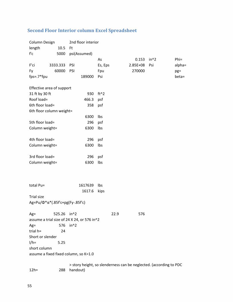
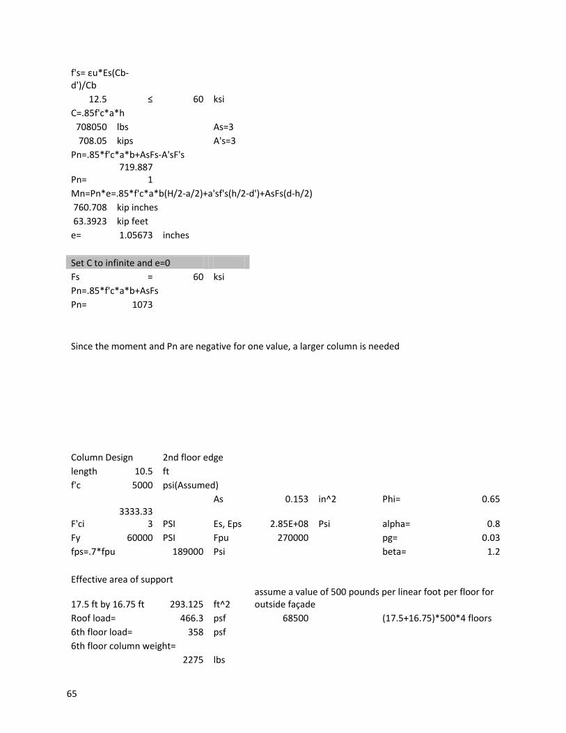
Second Floor Interior column Excel Spreadsheet
Column Design 2nd floor interior length 10.5 Ft
f'c 5000 psi(Assumed)
As 0.153 in^2 Phi=
F'ci 3333.333 PSI Es, Eps 2.85E+08 Psi alpha=
Fy 60000 PSI Fpu 270000
pg=
fps=.7*fpu 189000 Psi
beta=
Effective area of support 31 ft by 30 ft 930 ft^2
Roof load= 466.3 psf 6th floor load= 358 psf 6th floor column weight=
6300 lbs
5th floor load= 296 psf Column weight= 6300 lbs
4th floor load= 296 psf Column weight= 6300 lbs
3rd floor load= 296 psf Column weight= 6300 lbs
total Pu=
1617639 lbs
1617.6 kips
Trial size Ag=Pu/Φ*α*(.85f'c+pg(Fy-.85f'c)
Ag= 525.26 in^2 22.9 576 assume a trial size of 24 X 24, or 576 in^2
Ag= 576 in^2 trial h= 24
Short or slender l/h= 5.25 short column assume a fixed fixed column, so K=1.0
12h= 288
> story height, so slenderness can be neglected. (according to PDC handout)
56
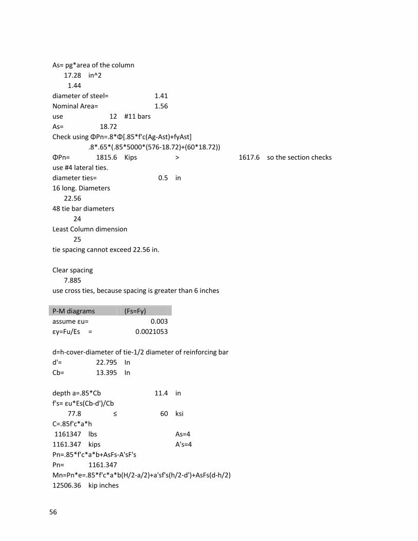
As= pg*area of the column 17.28 in^2
1.44 diameter of steel= 1.41
Nominal Area= 1.56 use 12 #11 bars As= 18.72
Check using ΦPn=.8*Φ[.85*f'c(Ag-Ast)+fyAst]
.8*.65*(.85*5000*(576-18.72)+(60*18.72))
ΦPn= 1815.6 Kips > 1617.6 so the section checks
use #4 lateral ties. diameter ties= 0.5 in
16 long. Diameters 22.56
48 tie bar diameters 24
Least Column dimension 25
tie spacing cannot exceed 22.56 in.
Clear spacing 7.885
use cross ties, because spacing is greater than 6 inches
P-M diagrams (Fs=Fy) assume εu= 0.003 εy=Fu/Es = 0.0021053
d=h-cover-diameter of tie-1/2 diameter of reinforcing bar d'= 22.795 In
Cb= 13.395 In
depth a=.85*Cb 11.4 in f's= εu*Es(Cb-d')/Cb
77.8 ≤ 60 ksi C=.85f'c*a*h
1161347 lbs
As=4 1161.347 kips
A's=4
Pn=.85*f'c*a*b+AsFs-A'sF's Pn= 1161.347
Mn=Pn*e=.85*f'c*a*b(H/2-a/2)+a'sf's(h/2-d')+AsFs(d-h/2) 12506.36 kip inches
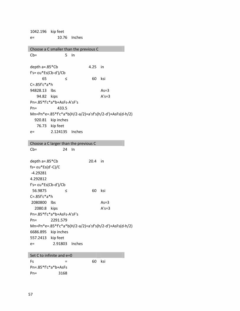
57
1042.196 kip feet e= 10.76 Inches
Choose a C smaller than the previous C Cb= 5 In
depth a=.85*Cb 4.25 in f's= εu*Es(Cb-d')/Cb
65 ≤ 60 ksi C=.85f'c*a*h
94828.13 lbs
As=3 94.82 kips
A's=3
Pn=.85*f'c*a*b+AsFs-A'sF's Pn= 433.5
Mn=Pn*e=.85*f'c*a*b(H/2-a/2)+a'sf's(h/2-d')+AsFs(d-h/2) 920.81 kip inches
76.73 kip feet e= 2.124135 Inches
Choose a C larger than the previous C Cb= 24 In
depth a=.85*Cb 20.4 in fs= εu*Es(d'-C)/C
-4.29281 4.292812 f's= εu*Es(Cb-d')/Cb
56.9875 ≤ 60 ksi C=.85f'c*a*h
2080800 lbs
As=3 2080.8 kips
A's=3
Pn=.85*f'c*a*b+AsFs-A'sF's Pn= 2291.579
Mn=Pn*e=.85*f'c*a*b(H/2-a/2)+a'sf's(h/2-d')+AsFs(d-h/2) 6686.895 kip inches
557.2413 kip feet e= 2.91803 Inches
Set C to infinite and e=0 Fs = 60 ksi Pn=.85*f'c*a*b+AsFs
Pn= 3168

58
Second Floor Exterior Middle Column Excel Spreadsheet
Column Design 2nd floor exterior centered column length 10.5 Ft
f'c 5000 psi(Assumed)
As 0.153 in^2 Phi=
F'ci 3333.33
3 PSI Es, Eps 2.85E+08 Psi alpha=
Fy 60000 PSI Fpu 270000
pg=
fps=.7*fpu 189000 Psi
beta=
Effective area of support
17.5 ft by 30 ft 525 ft^2 assume a value of 500 pounds per linear foot per floor for outside façade
Roof load= 466.3 psf 60000
(16.75)*500*4 floors
6th floor load= 358 psf 6th floor column weight=
2275 lbs
5th floor load= 296 psf Column weight= 6300 lbs
4th floor load= 296 psf Column weight= 6300 lbs
3rd floor load= 296 psf Column weight= 6300 lbs
total Pu=
980132.5 lbs
980.1325 kips
Trial size
Ag=Pu/Φ*α*(.85f'c+pg(Fy-.85f'c)
Ag= 318.3 in^2 17.8 324 assume a trial size of 24 X 24, or 576 in^2
Ag= 324 in^2 trial h= 18
Short or slender l/h= 7 short column assume a fixed fixed column, so K=1.0
59
12h= 216 > story height, so slenderness can be neglected. (according to PDC handout)
As= pg*area of the column 9.72 in^2
0.81 diameter of steel= 1.27
Nominal Area= 1.27 use 8 #10 bars As= 10.16
Check using ΦPn=.8*Φ[.85*f'c(Ag-Ast)+fyAst]
.8*.65*(.85*5000*(576-18.72)+(60*18.72))
ΦPn= 1010.5 Kips > 980.1325 so the section checks
use #3 lateral ties. diameter ties= 0.375 in
16 long. Diameters 20.32
48 tie bar diameters
18 Least Column dimension
18 tie spacing cannot exceed 18 in.
Clear spacing 8.095 in use cross ties, because spacing is greater than 6 inches
P-M diagrams (Fs=Fy) assume εu= 0.003 εy=Fu/E
s = 0.002105
3
d=h-cover-diameter of tie-1/2 diameter of reinforcing bar d'= 16.99 In
Cb= 9.98 In
depth a=.85*Cb
8.4862423 in
f's= εu*Es(Cb-d')/Cb
25.4673 ≤ 60 ksi C=.85f'c*a*h
649197 lbs
As=4
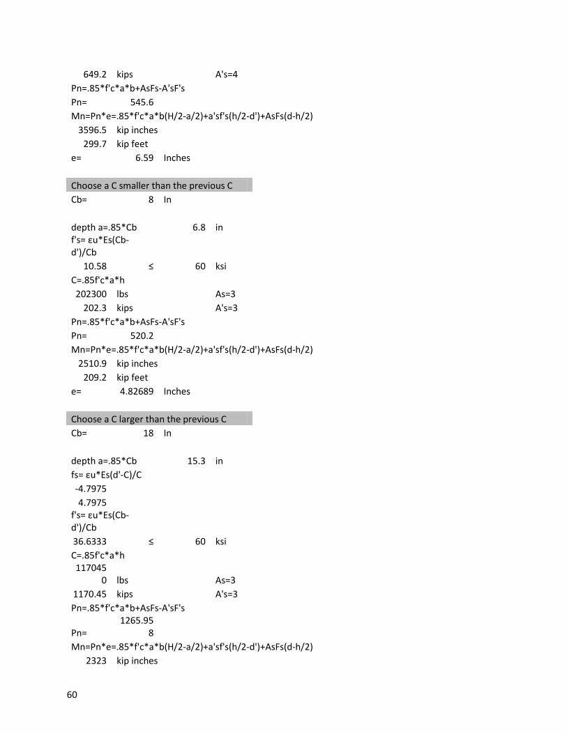
60
649.2 kips
A's=4 Pn=.85*f'c*a*b+AsFs-A'sF's
Pn= 545.6 Mn=Pn*e=.85*f'c*a*b(H/2-a/2)+a'sf's(h/2-d')+AsFs(d-h/2)
3596.5 kip inches 299.7 kip feet
e= 6.59 Inches
Choose a C smaller than the previous C Cb= 8 In
depth a=.85*Cb 6.8 in f's= εu*Es(Cb-
d')/Cb 10.58 ≤ 60 ksi
C=.85f'c*a*h 202300 lbs
As=3 202.3 kips
A's=3
Pn=.85*f'c*a*b+AsFs-A'sF's Pn= 520.2
Mn=Pn*e=.85*f'c*a*b(H/2-a/2)+a'sf's(h/2-d')+AsFs(d-h/2) 2510.9 kip inches
209.2 kip feet e= 4.82689 Inches
Choose a C larger than the previous C Cb= 18 In
depth a=.85*Cb 15.3 in fs= εu*Es(d'-C)/C
-4.7975 4.7975 f's= εu*Es(Cb-
d')/Cb 36.6333 ≤ 60 ksi
C=.85f'c*a*h 117045
0 lbs
As=3 1170.45 kips
A's=3
Pn=.85*f'c*a*b+AsFs-A'sF's
Pn= 1265.95
8 Mn=Pn*e=.85*f'c*a*b(H/2-a/2)+a'sf's(h/2-d')+AsFs(d-h/2)
2323 kip inches

61
193.5 kip feet e= 1.83492 Inches
Set C to infinite and e=0 Fs = 60 ksi Pn=.85*f'c*a*b+AsFs
Pn= 1857
62
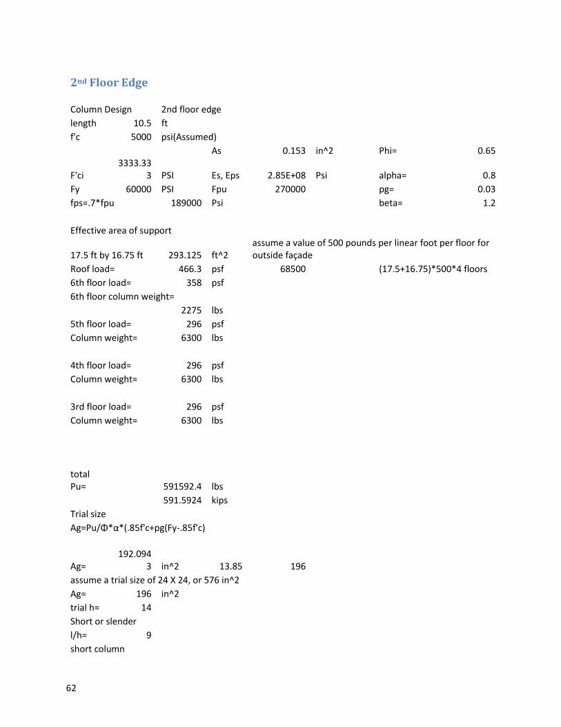
2nd Floor Edge
Column Design 2nd floor edge length 10.5 ft
f'c 5000 psi(Assumed)
As 0.153 in^2 Phi= 0.65
F'ci 3333.33
3 PSI Es, Eps 2.85E+08 Psi alpha= 0.8
Fy 60000 PSI Fpu 270000
pg= 0.03
fps=.7*fpu 189000 Psi
beta= 1.2
Effective area of support
17.5 ft by 16.75 ft 293.125 ft^2 assume a value of 500 pounds per linear foot per floor for outside façade
Roof load= 466.3 psf 68500
(17.5+16.75)*500*4 floors
6th floor load= 358 psf 6th floor column weight=
2275 lbs
5th floor load= 296 psf Column weight= 6300 lbs
4th floor load= 296 psf Column weight= 6300 lbs
3rd floor load= 296 psf Column weight= 6300 lbs
total Pu=
591592.4 lbs
591.5924 kips
Trial size Ag=Pu/Φ*α*(.85f'c+pg(Fy-.85f'c)
Ag=
192.0943 in^2 13.85 196
assume a trial size of 24 X 24, or 576 in^2 Ag= 196 in^2
trial h= 14 Short or slender l/h= 9 short column
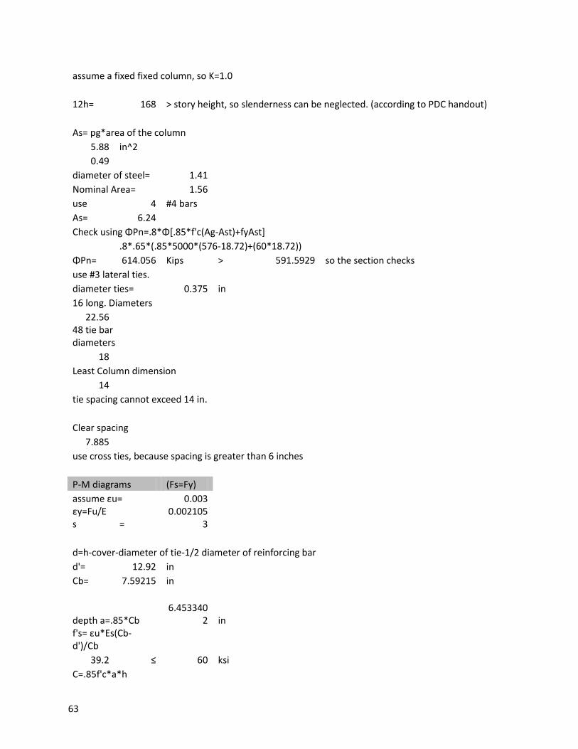
63
assume a fixed fixed column, so K=1.0
12h= 168 > story height, so slenderness can be neglected. (according to PDC handout)
As= pg*area of the column 5.88 in^2
0.49 diameter of steel= 1.41
Nominal Area= 1.56 use 4 #4 bars As= 6.24
Check using ΦPn=.8*Φ[.85*f'c(Ag-Ast)+fyAst]
.8*.65*(.85*5000*(576-18.72)+(60*18.72))
ΦPn= 614.056 Kips > 591.5929 so the section checks
use #3 lateral ties. diameter ties= 0.375 in
16 long. Diameters 22.56
48 tie bar diameters
18 Least Column dimension
14 tie spacing cannot exceed 14 in.
Clear spacing 7.885
use cross ties, because spacing is greater than 6 inches
P-M diagrams (Fs=Fy) assume εu= 0.003 εy=Fu/E
s = 0.002105
3
d=h-cover-diameter of tie-1/2 diameter of reinforcing bar d'= 12.92 in
Cb= 7.59215 in
depth a=.85*Cb
6.4533402 in
f's= εu*Es(Cb-d')/Cb
39.2 ≤ 60 ksi C=.85f'c*a*h
64
383973.7 lbs
As=4
383.9737 kips
A's=4
Pn=.85*f'c*a*b+AsFs-A'sF's
Pn= 185.416
5 Mn=Pn*e=.85*f'c*a*b(H/2-a/2)+a'sf's(h/2-d')+AsFs(d-h/2)
1304.314 kip inches
108.6929 kip feet
e= 7 inches
Choose a C smaller than the previous C Cb= 5 in
depth a=.85*Cb 4.25 in f's= εu*Es(Cb-
d')/Cb -
103.968 ≤ 60 ksi C=.85f'c*a*h
162562.5 lbs
As=3
162.5625 kips
A's=3
Pn=.85*f'c*a*b+AsFs-A'sF's Pn= -75.061
Mn=Pn*e=.85*f'c*a*b(H/2-a/2)+a'sf's(h/2-d')+AsFs(d-h/2) -
447.234 kip inches -
37.2695 kip feet e= 5.95829 inches
Choose a C larger than the previous C Cb= 14 in
depth a=.85*Cb 11.9 in fs= εu*Es(d'-C)/C
-6.59571
6.595714
65
f's= εu*Es(Cb-d')/Cb
12.5 ≤ 60 ksi C=.85f'c*a*h
708050 lbs
As=3 708.05 kips
A's=3
Pn=.85*f'c*a*b+AsFs-A'sF's
Pn= 719.887
1 Mn=Pn*e=.85*f'c*a*b(H/2-a/2)+a'sf's(h/2-d')+AsFs(d-h/2)
760.708 kip inches 63.3923 kip feet
e= 1.05673 inches
Set C to infinite and e=0 Fs = 60 ksi Pn=.85*f'c*a*b+AsFs
Pn= 1073
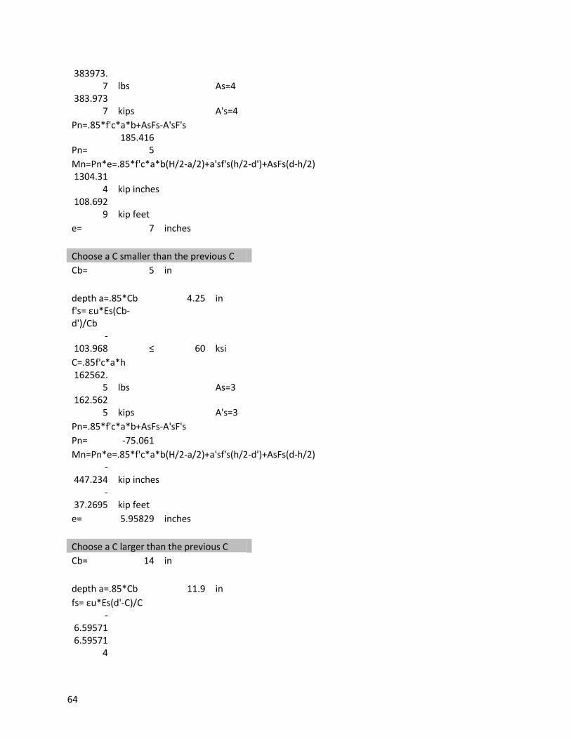
Since the moment and Pn are negative for one value, a larger column is needed
Column Design 2nd floor edge length 10.5 ft
f'c 5000 psi(Assumed)
As 0.153 in^2 Phi= 0.65
F'ci 3333.33
3 PSI Es, Eps 2.85E+08 Psi alpha= 0.8
Fy 60000 PSI Fpu 270000
pg= 0.03
fps=.7*fpu 189000 Psi
beta= 1.2
Effective area of support
17.5 ft by 16.75 ft 293.125 ft^2 assume a value of 500 pounds per linear foot per floor for outside façade
Roof load= 466.3 psf 68500
(17.5+16.75)*500*4 floors
6th floor load= 358 psf 6th floor column weight=
2275 lbs
66
5th floor load= 296 psf Column weight= 6300 lbs
4th floor load= 296 psf Column weight= 6300 lbs
3rd floor load= 296 psf Column weight= 6300 lbs
total Pu=
591592.94 lbs
591.59294 kips
Trial size Ag=Pu/Φ*α*(.85f'c+pg(Fy-.85f'c)
Ag= 192.093 in^2
13.8591 576
assume a trial size of 24 X 24, or 576 in^2 Ag= 576 in^2
trial h= 24 Short or slender l/h= 5.25 short column assume a fixed fixed column, so K=1.0
12h= 288 > story height, so slenderness can be neglected. (according to PDC handout)
As= pg*area of the column 17.28 in^2
1.44 diameter of steel= 1.41
Nominal Area= 1.56 use 4 #4 bars As= 6.24
Check using ΦPn=.8*Φ[.85*f'c(Ag-Ast)+fyAst]
.8*.65*(.85*5000*(576-18.72)+(60*18.72))
ΦPn= 1453 Kips > 591.5929 so the section checks
use #3 lateral ties. diameter ties= 0.375 in
16 long. Diameters
67
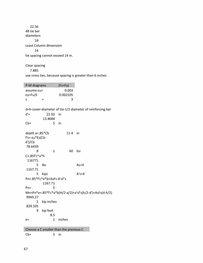
22.56 48 tie bar
diameters 18
Least Column dimension 14
tie spacing cannot exceed 14 in.
Clear spacing 7.885
use cross ties, because spacing is greater than 6 inches
P-M diagrams (Fs=Fy) assume εu= 0.003 εy=Fu/E
s = 0.002105
3
d=h-cover-diameter of tie-1/2 diameter of reinforcing bar d'= 22.92 in
Cb=
13.46845 in
depth a=.85*Cb 11.4 in f's= εu*Es(Cb-
d')/Cb 78.6439
8 ≤ 60 ksi C=.85f'c*a*h
1167715 lbs
As=4
1167.715 kips
A's=4
Pn=.85*f'c*a*b+AsFs-A'sF's
Pn= 1167.71
5 Mn=Pn*e=.85*f'c*a*b(H/2-a/2)+a'sf's(h/2-d')+AsFs(d-h/2)
9949.271 kip inches
829.1059 kip feet
e=
8.5 1 inches
Choose a C smaller than the previous C Cb= 5 in
68
depth a=.85*Cb 4.25 in f's= εu*Es(Cb-
d')/Cb 67.032 ≤ 60 ksi
C=.85f'c*a*h 94828.1
3 lbs
As=3 94.8281
3 kips
A's=3 Pn=.85*f'c*a*b+AsFs-A'sF's
Pn= 553.38 Mn=Pn*e=.85*f'c*a*b(H/2-a/2)+a'sf's(h/2-d')+AsFs(d-h/2)
2600.8 kip inches 216.734 kip feet
e=
4.699867 inches
Choose a C larger than the previous C Cb= 24 in
depth a=.85*Cb 20.4 in fs= εu*Es(d'-C)/C
-3.8475 3.8475
f's= εu*Es(Cb-d')/Cb
57.3 ≤ 60 ksi C=.85f'c*a*h
208080 lbs
As=3 2080.8 kips
A's=3
Pn=.85*f'c*a*b+AsFs-A'sF's
Pn= 2187.70
5 Mn=Pn*e=.85*f'c*a*b(H/2-a/2)+a'sf's(h/2-d')+AsFs(d-h/2)
5212.98 kip inches 434.415 kip feet
e=
2.3 3 inches
Set C to infinite and e=0

69
Shear Wall Excel Spreadsheet
Shear wall design https://engineering.purdue.edu/~frosch/
CE576/Time%20Saving%20Design%20Tips/Time%20Saving-Columns&Walls.pdf
Givens f'c 5000 psi
Ss 0.24 Sds 0.256 g S1 0.067 Sd1 0.107 g R 1.5 at existing 5 at addition
Cd 1.5 at existing 4.5 at addition high hazard occupancy
site class D importance factor 1.25
over strength factor 2.5 fy of steel 60,000 psi Reinforced concrete shear walls tributary area for each shear wall 945 square feet floor live load
floor 2-5 80 psf floor 1,6 100 psf' Snow load 43 psf Floor dead load
1st, 6th floor
150 psf
+ 15
165 2-5th floor
125 psf
+ 15
140 Earthquake loads
8704.8 1st floor 37497.6 2nd 56246.4 3rd 74995.2 4th 93744 5th 132580.8 6th
Area per floor 30 X 10.5
70
315 sq ft
Earthquake load is much greater than wind, so the load combo used will be 1.2D ± 1.0E + 0.5L + 0.2S
First floor load 251.1918 kips second
242.1846 kips
third
260.9334 kips fourth
279.6822 kips
fifth
298.431 kips 6th
375.0678 kips
Check shear strength in 1st story 1707.4908 kips
Vu=1.3*total shear 2219.73804 kips from table 6 ΦVc=30*12.4 762.6 kips ΦVs=AvFyd/s number 6 bars Av= 0.441786 Fy 60 d= 9.6 s= 12 ΦVs 16.9646 from table 5, use number 6 bars at a spacing of 12 inches
Check shear at 2nd story Vu=1.3* the floor loads except the 1st
1893.1887 still higher than Vc, so number 6 shear bars should be added at a spacing of 12 inches
Shear at 3rd floor Vu=
1578.34872 as above, use number 6 bars at a spacing of 12 inches, both horizontally and vertically
Shear at 4th floor Vu=
1239.1353
Use #6 bars at a spacing of 12 inches for each floor
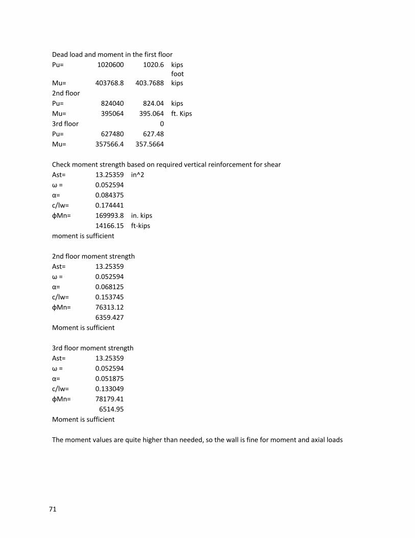
71
Dead load and moment in the first floor Pu= 1020600 1020.6 kips
Mu= 403768.8 403.7688 foot kips
2nd floor Pu= 824040 824.04 kips
Mu= 395064 395.064 ft. Kips 3rd floor
0
Pu= 627480 627.48 Mu= 357566.4 357.5664
Check moment strength based on required vertical reinforcement for shear Ast= 13.25359 in^2
ω = 0.052594 α= 0.084375 c/lw= 0.174441 фMn= 169993.8 in. kips
14166.15 ft-kips
moment is sufficient
2nd floor moment strength Ast= 13.25359
ω = 0.052594 α= 0.068125 c/lw= 0.153745 фMn= 76313.12
6359.427
Moment is sufficient
3rd floor moment strength Ast= 13.25359
ω = 0.052594 α= 0.051875 c/lw= 0.133049 фMn= 78179.41
6514.95
Moment is sufficient
The moment values are quite higher than needed, so the wall is fine for moment and axial loads
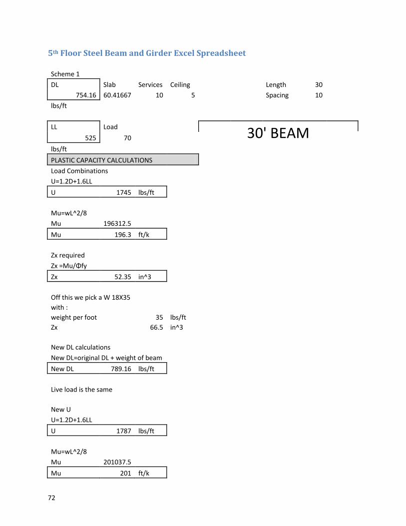
72
5th Floor Steel Beam and Girder Excel Spreadsheet
Scheme 1 DL Slab Services Ceiling
Length 30
754.16 60.41667 10 5
Spacing 10 lbs/ft
LL Load 30' BEAM 525 70 lbs/ft
PLASTIC CAPACITY CALCULATIONS Load Combinations
U=1.2D+1.6LL U 1745 lbs/ft
Mu=wL^2/8 Mu 196312.5 Mu 196.3 ft/k
Zx required Zx =Mu/Φfy Zx 52.35 in^3
Off this we pick a W 18X35 with :
weight per foot 35 lbs/ft Zx
66.5 in^3
New DL calculations New DL=original DL + weight of beam
New DL 789.16 lbs/ft
Live load is the same
New U U=1.2D+1.6LL
U 1787 lbs/ft
Mu=wL^2/8 Mu 201037.5 Mu 201 ft/k
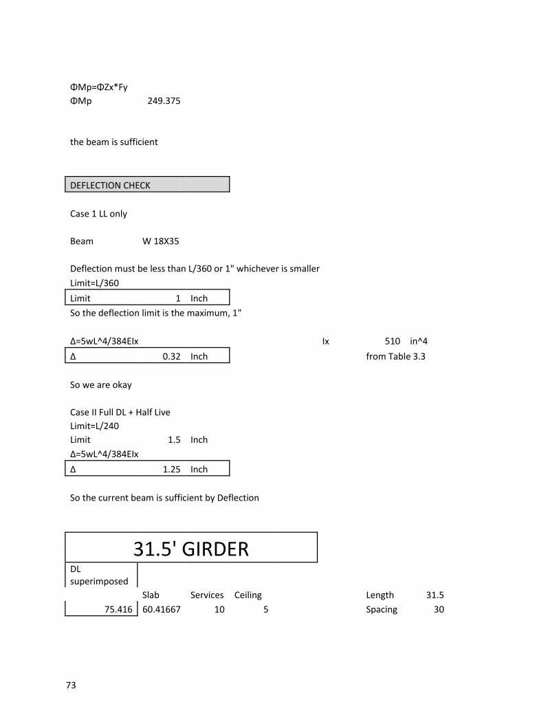
73
ΦMp=ΦZx*Fy ΦMp 249.375
the beam is sufficient
DEFLECTION CHECK
Case 1 LL only
Beam W 18X35
Deflection must be less than L/360 or 1" whichever is smaller Limit=L/360
Limit 1 Inch So the deflection limit is the maximum, 1"
Δ=5wL^4/384EIx
Ix 510 in^4 Δ 0.32 Inch
from Table 3.3
So we are okay
Case II Full DL + Half Live Limit=L/240
Limit 1.5 Inch Δ=5wL^4/384EIx
Δ 1.25 Inch
So the current beam is sufficient by Deflection
31.5' GIRDER
DL superimposed
Slab Services Ceiling
Length 31.5
75.416 60.41667 10 5
Spacing 30
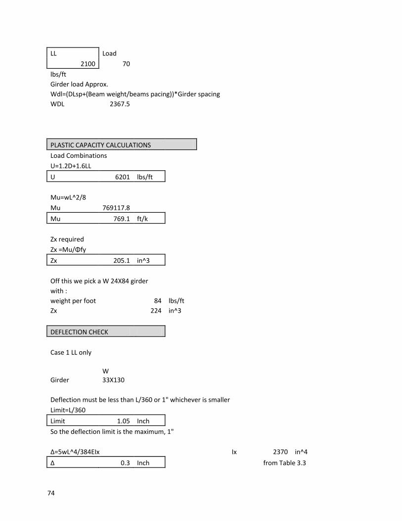
74
LL Load
2100 70
lbs/ft Girder load Approx.
Wdl=(DLsp+(Beam weight/beams pacing))*Girder spacing WDL 2367.5
PLASTIC CAPACITY CALCULATIONS Load Combinations
U=1.2D+1.6LL U 6201 lbs/ft
Mu=wL^2/8 Mu 769117.8 Mu 769.1 ft/k
Zx required Zx =Mu/Φfy Zx 205.1 in^3
Off this we pick a W 24X84 girder with :
weight per foot 84 lbs/ft Zx
224 in^3
DEFLECTION CHECK
Case 1 LL only
Girder
W 33X130
Deflection must be less than L/360 or 1" whichever is smaller Limit=L/360
Limit 1.05 Inch So the deflection limit is the maximum, 1"
Δ=5wL^4/384EIx
Ix 2370 in^4 Δ 0.3 Inch
from Table 3.3
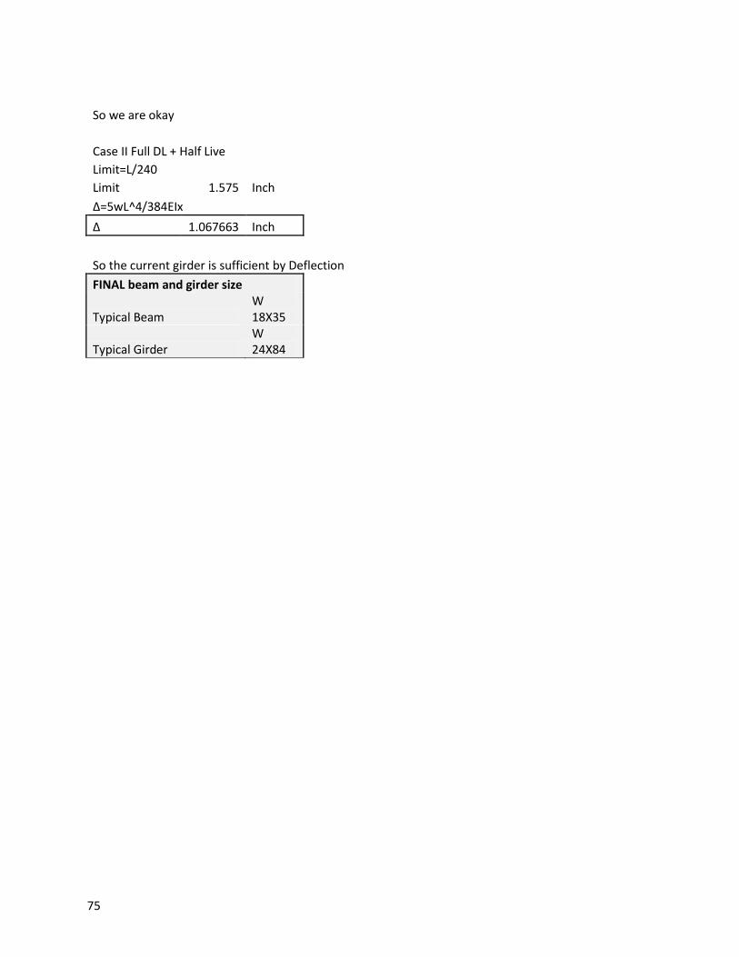
75
So we are okay
Case II Full DL + Half Live Limit=L/240
Limit 1.575 Inch Δ=5wL^4/384EIx
Δ 1.067663 Inch
So the current girder is sufficient by Deflection FINAL beam and girder size
Typical Beam
W 18X35
Typical Girder
W 24X84
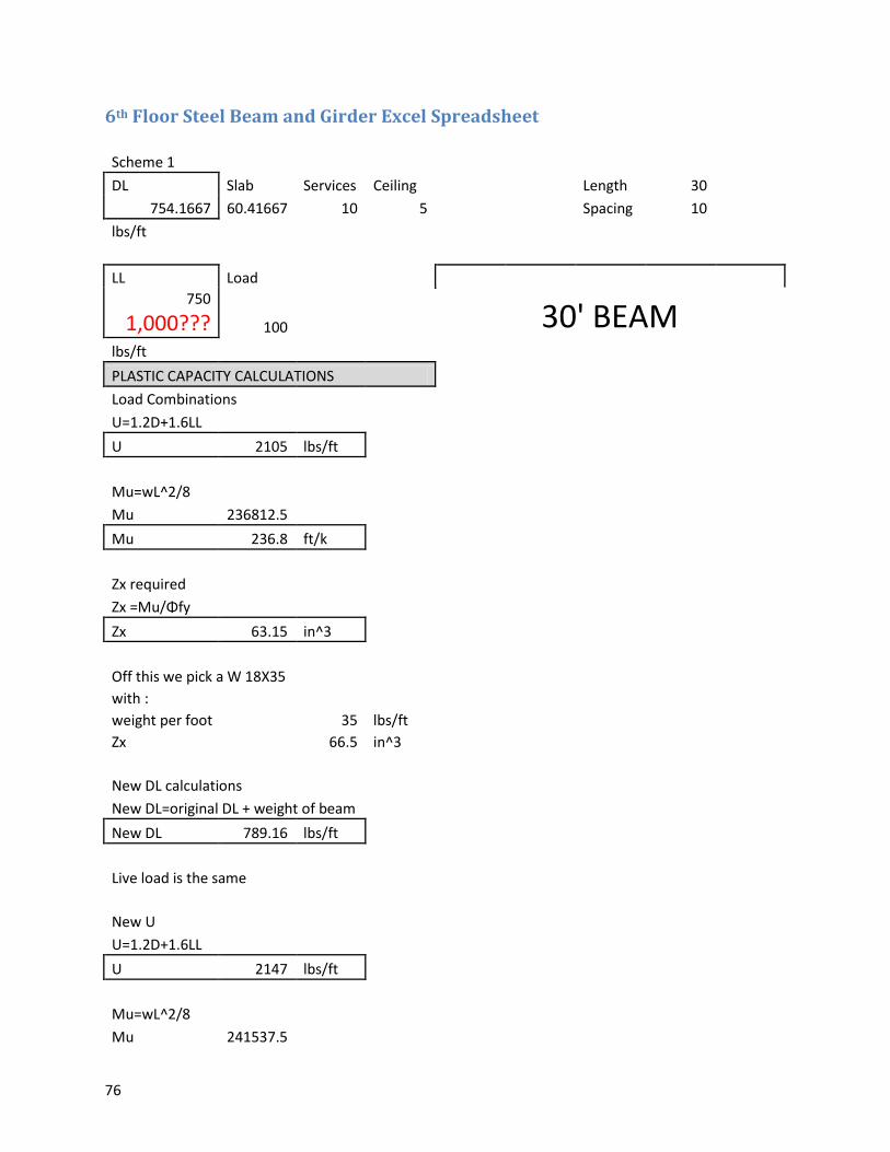
76
6th Floor Steel Beam and Girder Excel Spreadsheet
Scheme 1 DL Slab Services Ceiling
Length 30
754.1667 60.41667 10 5
Spacing 10 lbs/ft
LL Load
30' BEAM 750
1,000??? 100 lbs/ft
PLASTIC CAPACITY CALCULATIONS Load Combinations
U=1.2D+1.6LL U 2105 lbs/ft
Mu=wL^2/8 Mu 236812.5 Mu 236.8 ft/k
Zx required Zx =Mu/Φfy Zx 63.15 in^3
Off this we pick a W 18X35 with :
weight per foot 35 lbs/ft Zx
66.5 in^3
New DL calculations New DL=original DL + weight of beam
New DL 789.16 lbs/ft
Live load is the same
New U U=1.2D+1.6LL
U 2147 lbs/ft
Mu=wL^2/8 Mu 241537.5
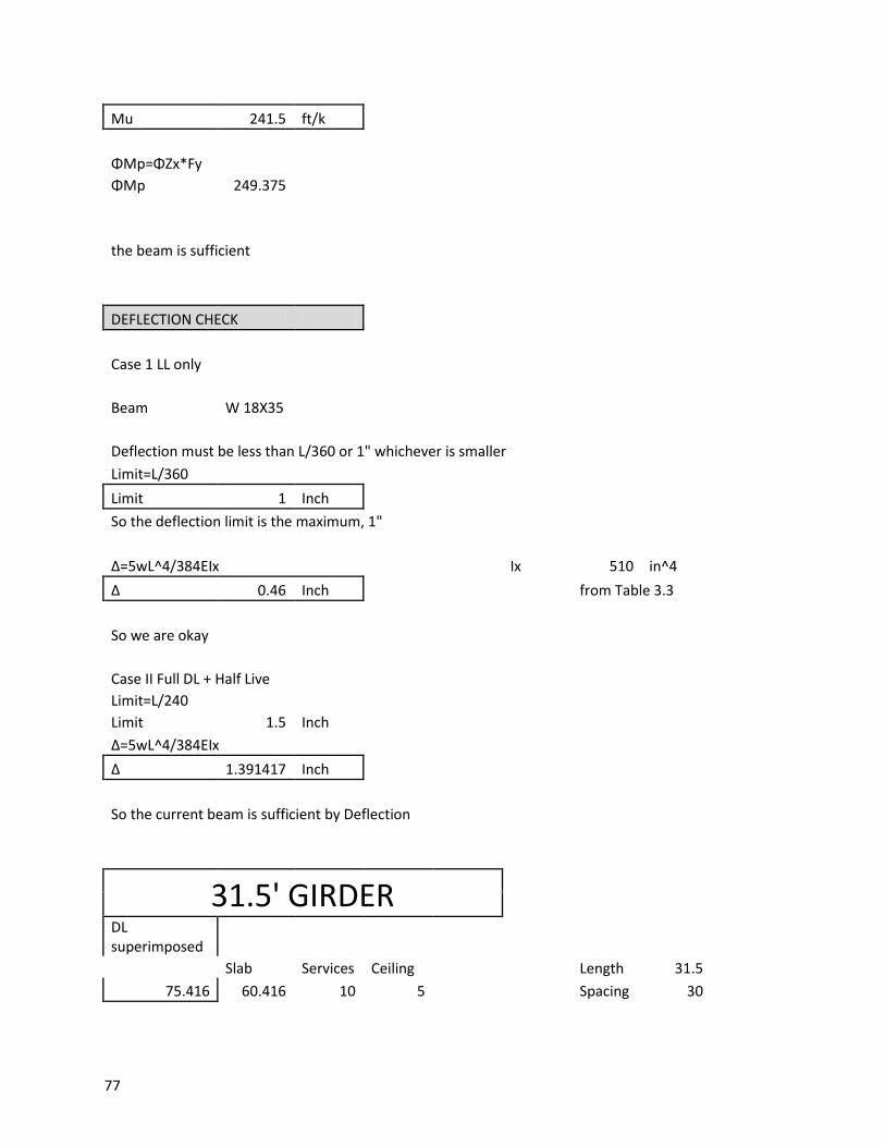
77
Mu 241.5 ft/k
ΦMp=ΦZx*Fy ΦMp 249.375
the beam is sufficient
DEFLECTION CHECK
Case 1 LL only
Beam W 18X35
Deflection must be less than L/360 or 1" whichever is smaller Limit=L/360
Limit 1 Inch So the deflection limit is the maximum, 1"
Δ=5wL^4/384EIx
Ix 510 in^4 Δ 0.46 Inch
from Table 3.3
So we are okay
Case II Full DL + Half Live Limit=L/240
Limit 1.5 Inch Δ=5wL^4/384EIx
Δ 1.391417 Inch
So the current beam is sufficient by Deflection
31.5' GIRDER
DL superimposed
Slab Services Ceiling
Length 31.5
75.416 60.416 10 5
Spacing 30
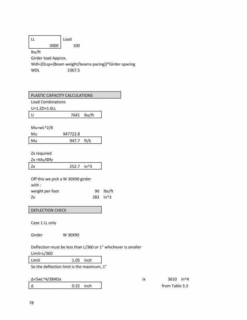
78
LL Load
3000 100
lbs/ft Girder load Approx.
Wdl=(DLsp+(Beam weight/beams pacing))*Girder spacing WDL 2367.5
PLASTIC CAPACITY CALCULATIONS Load Combinations
U=1.2D+1.6LL U 7641 lbs/ft
Mu=wL^2/8 Mu 947722.8 Mu 947.7 ft/k
Zx required Zx =Mu/Φfy Zx 252.7 in^3
Off this we pick a W 30X90 girder with :
weight per foot 90 lbs/ft Zx
283 in^3
DEFLECTION CHECK
Case 1 LL only
Girder W 30X90
Deflection must be less than L/360 or 1" whichever is smaller Limit=L/360
Limit 1.05 inch So the deflection limit is the maximum, 1"
Δ=5wL^4/384EIx
Ix 3610 in^4 Δ 0.32 inch
from Table 3.3
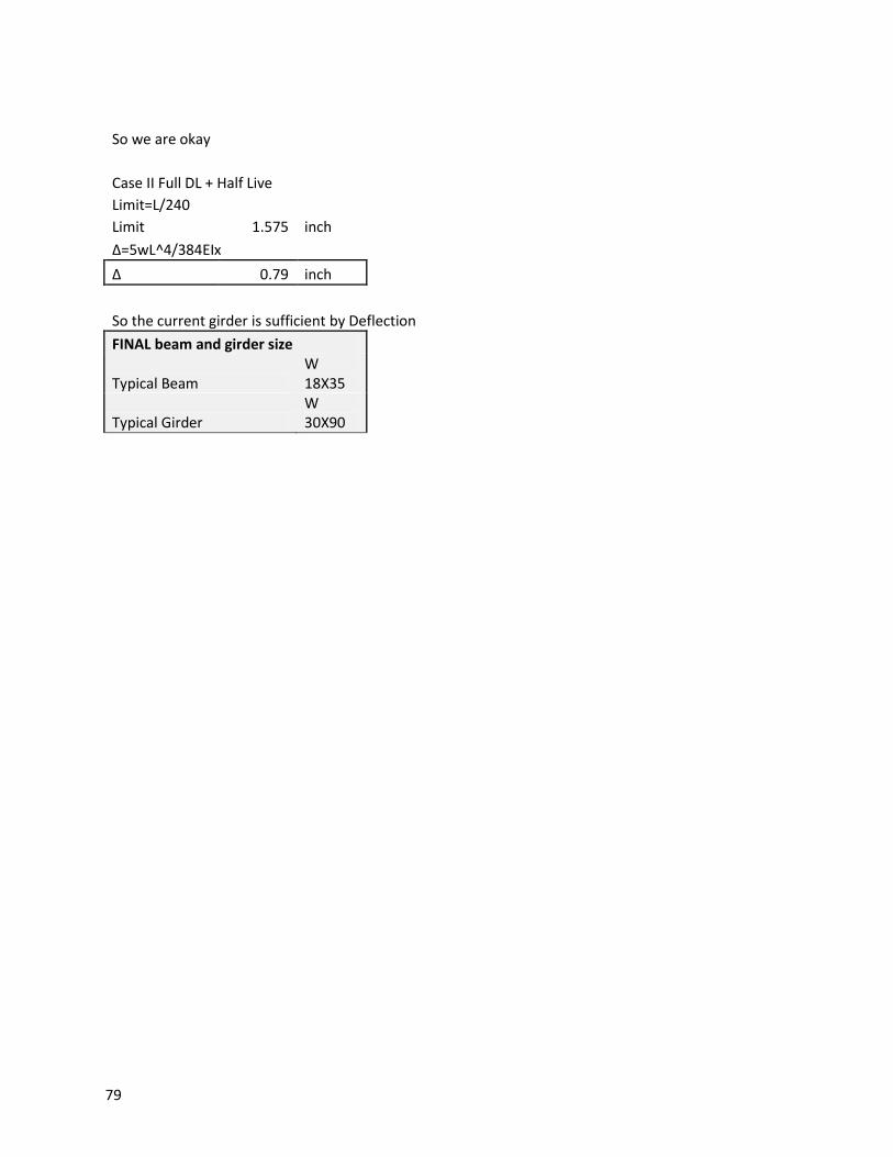
79
So we are okay
Case II Full DL + Half Live Limit=L/240
Limit 1.575 inch Δ=5wL^4/384EIx
Δ 0.79 inch
So the current girder is sufficient by Deflection FINAL beam and girder size
Typical Beam
W 18X35
Typical Girder
W 30X90
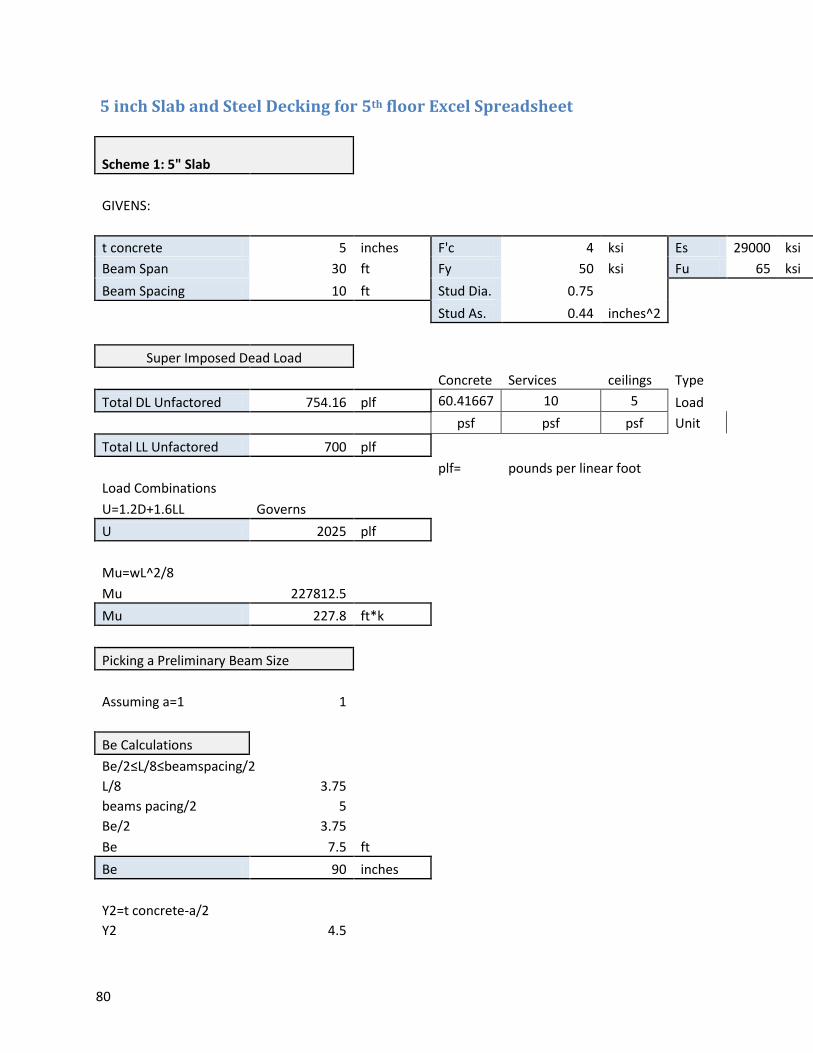
80
5 inch Slab and Steel Decking for 5th floor Excel Spreadsheet
Scheme 1: 5" Slab
GIVENS:
t concrete 5 inches F'c 4 ksi Es 29000 ksi
Beam Span 30 ft Fy 50 ksi Fu 65 ksi
Beam Spacing 10 ft Stud Dia. 0.75
Stud As. 0.44 inches^2
Super Imposed Dead Load
Concrete Services ceilings Type
Total DL Unfactored 754.16 plf 60.41667 10 5 Load
psf psf psf Unit
Total LL Unfactored 700 plf
plf= pounds per linear foot
Load Combinations U=1.2D+1.6LL Governs
U 2025 plf
Mu=wL^2/8 Mu 227812.5
Mu 227.8 ft*k
Picking a Preliminary Beam Size
Assuming a=1 1
Be Calculations Be/2≤L/8≤beamspacing/2
L/8 3.75 beams pacing/2 5 Be/2 3.75 Be 7.5 ft
Be 90 inches
Y2=t concrete-a/2 Y2 4.5
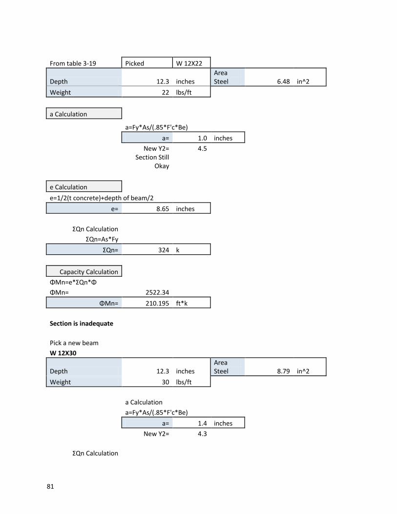
81
From table 3-19 Picked W 12X22
Depth 12.3 inches Area Steel 6.48 in^2
Weight 22 lbs/ft
a Calculation
a=Fy*As/(.85*F'c*Be)
a= 1.0 inches
New Y2= 4.5
Section Still Okay
e Calculation e=1/2(t concrete)+depth of beam/2
e= 8.65 inches
ΣQn Calculation ΣQn=As*Fy ΣQn= 324 k
Capacity Calculation ΦMn=e*ΣQn*Φ ΦMn= 2522.34
ΦMn= 210.195 ft*k
Section is inadequate
Pick a new beam W 12X30
Depth 12.3 inches Area Steel 8.79 in^2
Weight 30 lbs/ft
a Calculation
a=Fy*As/(.85*F'c*Be)
a= 1.4 inches
New Y2= 4.3
ΣQn Calculation
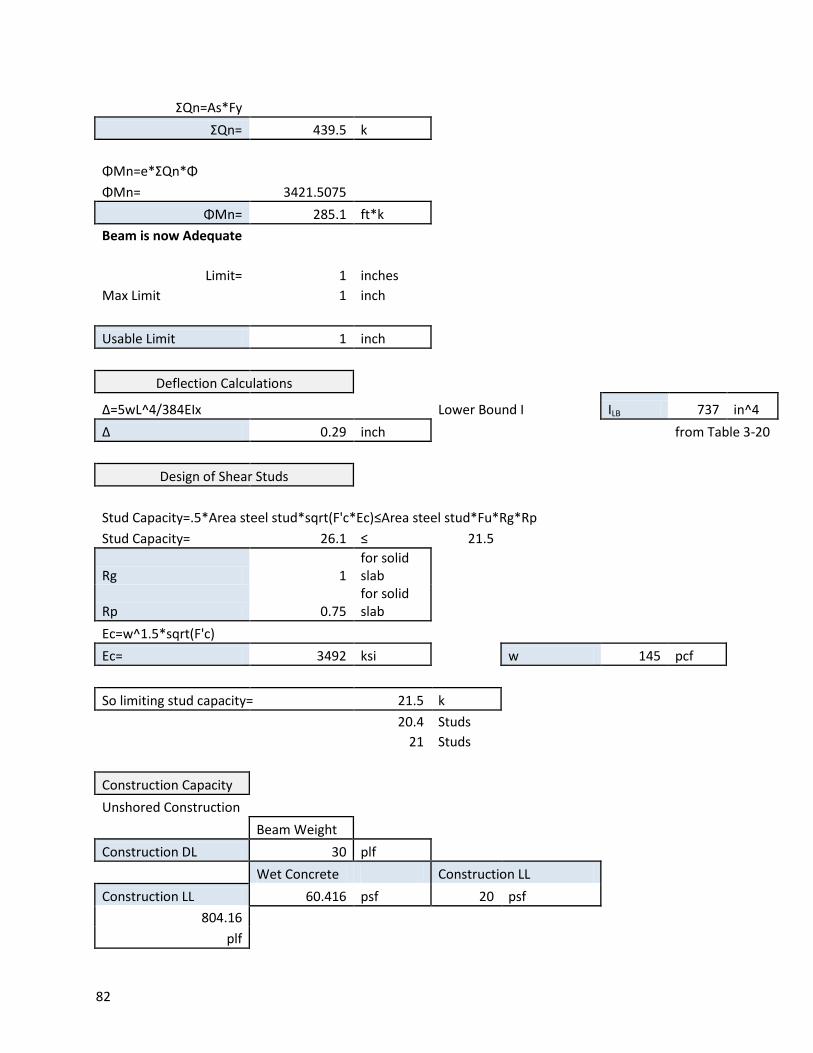
82
ΣQn=As*Fy ΣQn= 439.5 k
ΦMn=e*ΣQn*Φ ΦMn= 3421.5075
ΦMn= 285.1 ft*k Beam is now Adequate
Limit= 1 inches Max Limit 1 inch
Usable Limit 1 inch
Deflection Calculations
Δ=5wL^4/384EIx
Lower Bound I ILB 737 in^4 Δ 0.29 inch
from Table 3-20
Design of Shear Studs
Stud Capacity=.5*Area steel stud*sqrt(F'c*Ec)≤Area steel stud*Fu*Rg*Rp Stud Capacity= 26.1 ≤ 21.5
Rg 1 for solid slab
Rp 0.75
for solid slab
Ec=w^1.5*sqrt(F'c) Ec= 3492 ksi
w 145 pcf
So limiting stud capacity= 21.5 k
20.4 Studs
21 Studs
Construction Capacity Unshored Construction
Beam Weight
Construction DL 30 plf
Wet Concrete Construction LL
Construction LL 60.416 psf 20 psf 804.16
plf
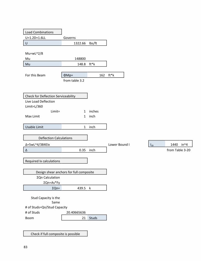
83
Load Combinations U=1.2D+1.6LL Governs
U 1322.66 lbs/ft
Mu=wL^2/8 Mu 148800
Mu 148.8 ft*k
For this Beam ΦMp= 162 ft*k
from table 3.2
Check for Deflection Serviceability Live Load Deflection
Limit=L/360 Limit= 1 inches
Max Limit 1 inch
Usable Limit 1 inch
Deflection Calculations
Δ=5wL^4/384EIx
Lower Bound I ILB 1440 in^4 Δ 0.35 inch
from Table 3-20
Required Ix calculations
Design shear anchors for full composite ΣQn Calculation
ΣQn=As*Fy ΣQn= 439.5 k
Stud Capacity is the Same
# of Studs=Qn/Stud Capacity # of Studs 20.40665636 Boom 21 Studs
Check if full composite is possible
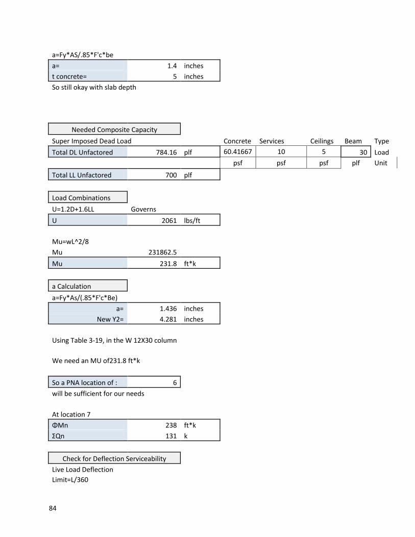
84
a=Fy*AS/.85*F'c*be a= 1.4 inches
t concrete= 5 inches So still okay with slab depth
Needed Composite Capacity Super Imposed Dead Load
Concrete Services Ceilings Beam Type Total DL Unfactored 784.16 plf 60.41667 10 5 30 Load
psf psf psf plf Unit
Total LL Unfactored 700 plf
Load Combinations U=1.2D+1.6LL Governs
U 2061 lbs/ft
Mu=wL^2/8 Mu 231862.5
Mu 231.8 ft*k
a Calculation a=Fy*As/(.85*F'c*Be) a= 1.436 inches
New Y2= 4.281 inches
Using Table 3-19, in the W 12X30 column
We need an MU of231.8 ft*k
So a PNA location of : 6 will be sufficient for our needs
At location 7 ΦMn 238 ft*k
ΣQn 131 k
Check for Deflection Serviceability Live Load Deflection
Limit=L/360
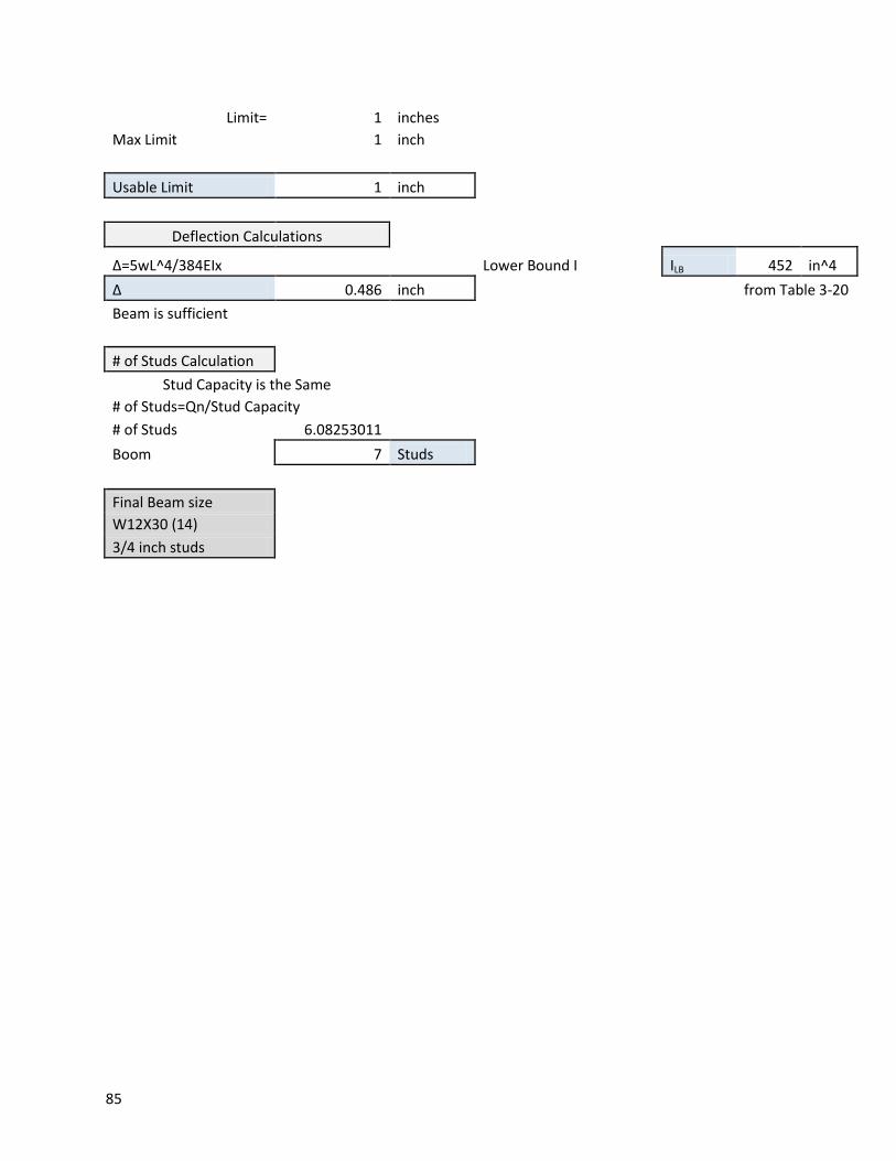
85
Limit= 1 inches Max Limit 1 inch
Usable Limit 1 inch
Deflection Calculations
Δ=5wL^4/384EIx
Lower Bound I ILB 452 in^4 Δ 0.486 inch
from Table 3-20
Beam is sufficient
# of Studs Calculation Stud Capacity is the Same
# of Studs=Qn/Stud Capacity # of Studs 6.08253011 Boom 7 Studs
Final Beam size W12X30 (14) 3/4 inch studs
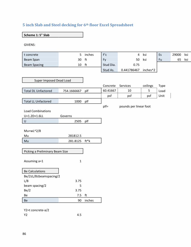
86
5 inch Slab and Steel decking for 6th floor Excel Spreadsheet
Scheme 1: 5" Slab
GIVENS:
t concrete 5 inches F'c 4 ksi Es 29000 ksi
Beam Span 30 ft Fy 50 ksi Fu 65 ksi
Beam Spacing 10 ft Stud Dia. 0.75
Stud As. 0.441786467 inches^2
Super Imposed Dead Load
Concrete Services ceilings Type
Total DL Unfactored 754.1666667 plf 60.41667 10 5 Load
psf psf psf Unit
Total LL Unfactored 1000 plf
plf= pounds per linear foot
Load Combinations U=1.2D+1.6LL Governs
U 2505 plf
Mu=wL^2/8 Mu 281812.5
Mu 281.8125 ft*k
Picking a Preliminary Beam Size
Assuming a=1 1
Be Calculations Be/2≤L/8≤beamspacing/2
L/8 3.75 beam spacing/2 5 Be/2 3.75 Be 7.5 ft
Be 90 inches
Y2=t concrete-a/2 Y2 4.5
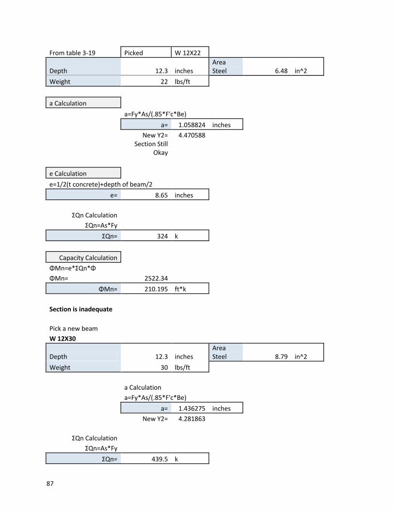
87
From table 3-19 Picked W 12X22
Depth 12.3 inches Area Steel 6.48 in^2
Weight 22 lbs/ft
a Calculation
a=Fy*As/(.85*F'c*Be)
a= 1.058824 inches
New Y2= 4.470588
Section Still Okay
e Calculation e=1/2(t concrete)+depth of beam/2
e= 8.65 inches
ΣQn Calculation ΣQn=As*Fy ΣQn= 324 k
Capacity Calculation ΦMn=e*ΣQn*Φ ΦMn= 2522.34
ΦMn= 210.195 ft*k
Section is inadequate
Pick a new beam W 12X30
Depth 12.3 inches Area Steel 8.79 in^2
Weight 30 lbs/ft
a Calculation
a=Fy*As/(.85*F'c*Be)
a= 1.436275 inches
New Y2= 4.281863
ΣQn Calculation ΣQn=As*Fy ΣQn= 439.5 k
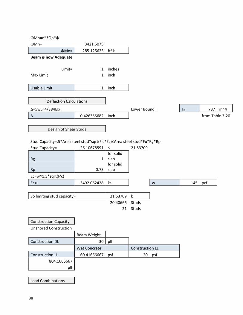
88
ΦMn=e*ΣQn*Φ ΦMn= 3421.5075
ΦMn= 285.125625 ft*k Beam is now Adequate
Limit= 1 inches Max Limit 1 inch
Usable Limit 1 inch
Deflection Calculations
Δ=5wL^4/384EIx
Lower Bound I ILB 737 in^4 Δ 0.426355682 inch
from Table 3-20
Design of Shear Studs
Stud Capacity=.5*Area steel stud*sqrt(F'c*Ec)≤Area steel stud*Fu*Rg*Rp Stud Capacity= 26.10678591 ≤ 21.53709
Rg 1 for solid slab
Rp 0.75
for solid slab
Ec=w^1.5*sqrt(F'c) Ec= 3492.062428 ksi
w 145 pcf
So limiting stud capacity= 21.53709 k
20.40666 Studs
21 Studs
Construction Capacity Unshored Construction
Beam Weight
Construction DL 30 plf
Wet Concrete Construction LL
Construction LL 60.41666667 psf 20 psf 804.1666667
plf
Load Combinations
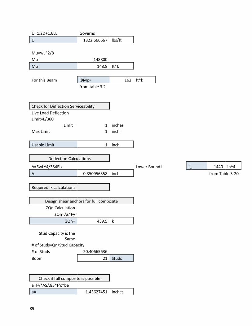
89
U=1.2D+1.6LL Governs U 1322.666667 lbs/ft
Mu=wL^2/8 Mu 148800
Mu 148.8 ft*k
For this Beam ΦMp= 162 ft*k
from table 3.2
Check for Deflection Serviceability Live Load Deflection
Limit=L/360 Limit= 1 inches
Max Limit 1 inch
Usable Limit 1 inch
Deflection Calculations
Δ=5wL^4/384EIx
Lower Bound I ILB 1440 in^4 Δ 0.350956358 inch
from Table 3-20
Required Ix calculations
Design shear anchors for full composite ΣQn Calculation
ΣQn=As*Fy ΣQn= 439.5 k
Stud Capacity is the Same
# of Studs=Qn/Stud Capacity # of Studs 20.40665636 Boom 21 Studs
Check if full composite is possible a=Fy*AS/.85*F'c*be
a= 1.43627451 inches
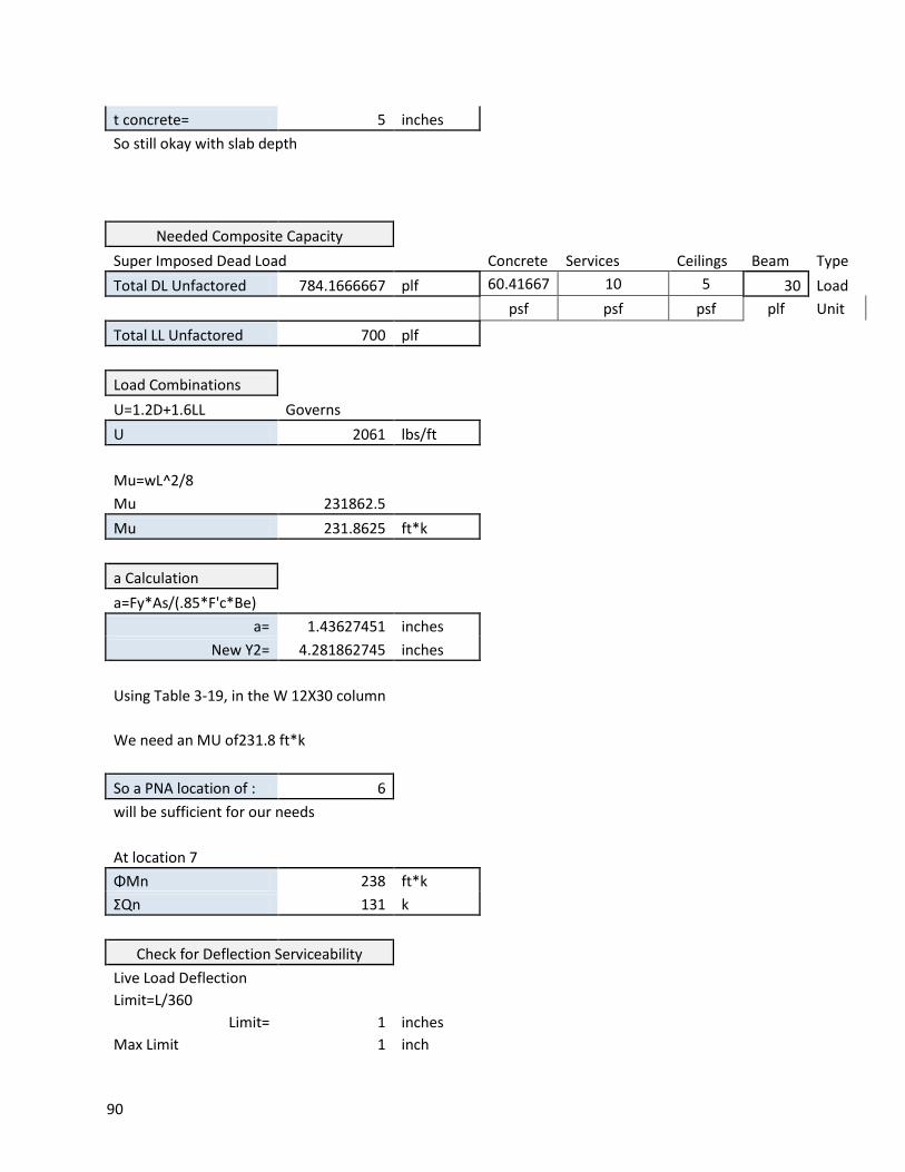
90
t concrete= 5 inches So still okay with slab depth
Needed Composite Capacity Super Imposed Dead Load
Concrete Services Ceilings Beam Type Total DL Unfactored 784.1666667 plf 60.41667 10 5 30 Load
psf psf psf plf Unit
Total LL Unfactored 700 plf
Load Combinations U=1.2D+1.6LL Governs
U 2061 lbs/ft
Mu=wL^2/8 Mu 231862.5
Mu 231.8625 ft*k
a Calculation a=Fy*As/(.85*F'c*Be) a= 1.43627451 inches
New Y2= 4.281862745 inches
Using Table 3-19, in the W 12X30 column
We need an MU of231.8 ft*k
So a PNA location of : 6 will be sufficient for our needs
At location 7 ΦMn 238 ft*k
ΣQn 131 k
Check for Deflection Serviceability Live Load Deflection
Limit=L/360 Limit= 1 inches
Max Limit 1 inch
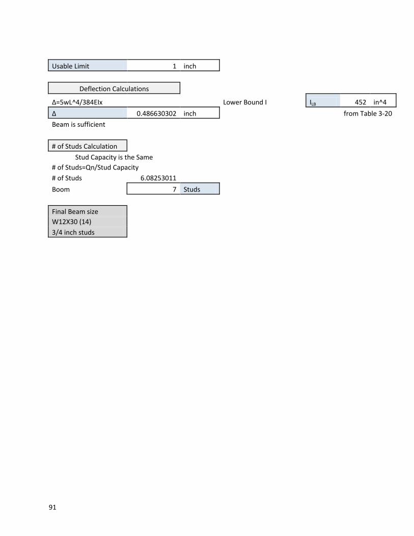
91
Usable Limit 1 inch
Deflection Calculations
Δ=5wL^4/384EIx
Lower Bound I ILB 452 in^4 Δ 0.486630302 inch
from Table 3-20
Beam is sufficient
# of Studs Calculation Stud Capacity is the Same
# of Studs=Qn/Stud Capacity # of Studs 6.08253011 Boom 7 Studs
Final Beam size W12X30 (14) 3/4 inch studs
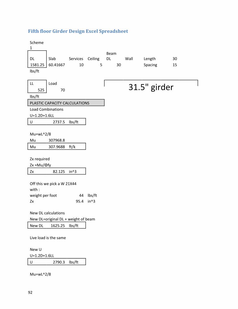
92
Fifth floor Girder Design Excel Spreadsheet
Scheme 1
DL Slab Services Ceiling Beam DL Wall Length 30
1581.25 60.41667 10 5 30
Spacing 15 lbs/ft
LL Load 31.5" girder 525 70 lbs/ft
PLASTIC CAPACITY CALCULATIONS Load Combinations
U=1.2D+1.6LL U 2737.5 lbs/ft
Mu=wL^2/8 Mu 307968.8 Mu 307.9688 ft/k
Zx required Zx =Mu/Φfy Zx 82.125 in^3
Off this we pick a W 21X44 with :
weight per foot 44 lbs/ft Zx
95.4 in^3
New DL calculations New DL=original DL + weight of beam
New DL 1625.25 lbs/ft
Live load is the same
New U U=1.2D+1.6LL
U 2790.3 lbs/ft
Mu=wL^2/8
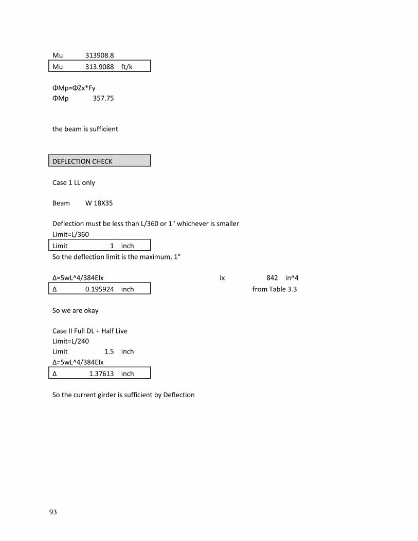
93
Mu 313908.8 Mu 313.9088 ft/k
ΦMp=ΦZx*Fy ΦMp 357.75
the beam is sufficient
DEFLECTION CHECK
Case 1 LL only
Beam W 18X35
Deflection must be less than L/360 or 1" whichever is smaller Limit=L/360
Limit 1 inch So the deflection limit is the maximum, 1"
Δ=5wL^4/384EIx
Ix 842 in^4 Δ 0.195924 inch
from Table 3.3
So we are okay
Case II Full DL + Half Live Limit=L/240
Limit 1.5 inch Δ=5wL^4/384EIx
Δ 1.37613 inch
So the current girder is sufficient by Deflection
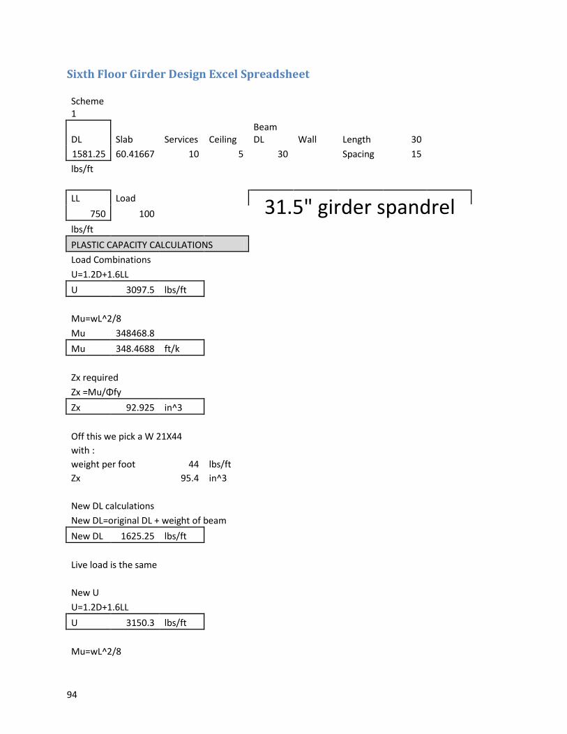
94
Sixth Floor Girder Design Excel Spreadsheet
Scheme 1
DL Slab Services Ceiling Beam DL Wall Length 30
1581.25 60.41667 10 5 30
Spacing 15 lbs/ft
LL Load 31.5" girder spandrel 750 100 lbs/ft
PLASTIC CAPACITY CALCULATIONS Load Combinations
U=1.2D+1.6LL U 3097.5 lbs/ft
Mu=wL^2/8 Mu 348468.8 Mu 348.4688 ft/k
Zx required Zx =Mu/Φfy Zx 92.925 in^3
Off this we pick a W 21X44 with :
weight per foot 44 lbs/ft Zx
95.4 in^3
New DL calculations New DL=original DL + weight of beam
New DL 1625.25 lbs/ft
Live load is the same
New U U=1.2D+1.6LL
U 3150.3 lbs/ft
Mu=wL^2/8

95
Mu 354408.8 Mu 354.4088 ft/k
ΦMp=ΦZx*Fy ΦMp 357.75
the beam is sufficient
DEFLECTION CHECK
Case 1 LL only
Beam W 18X35
Deflection must be less than L/360 or 1" whichever is smaller Limit=L/360
Limit 1 inch So the deflection limit is the maximum, 1"
Δ=5wL^4/384EIx
Ix 842 in^4 Δ 0.279891 inch
from Table 3.3
So we are okay
Case II Full DL + Half Live Limit=L/240
Limit 1.5 inch Δ=5wL^4/384EIx
Δ 1.460097 inch
So the current girder is sufficient by Deflection
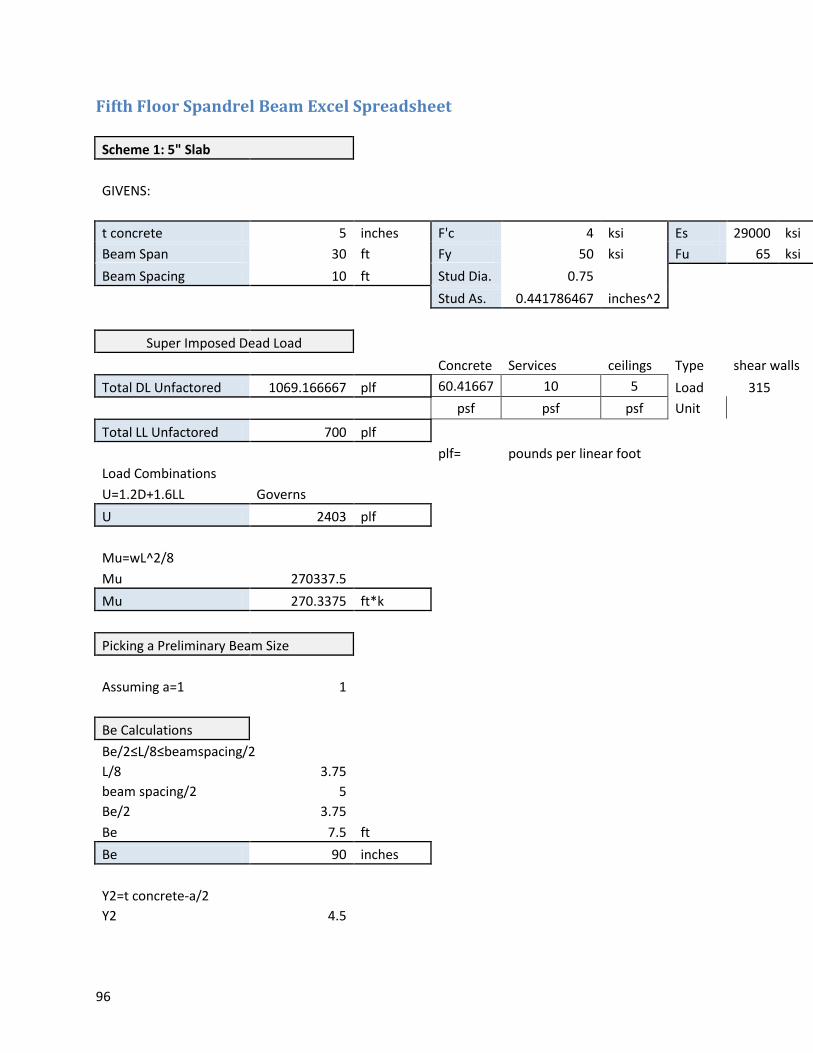
96
Fifth Floor Spandrel Beam Excel Spreadsheet
Scheme 1: 5" Slab
GIVENS:
t concrete 5 inches F'c 4 ksi Es 29000 ksi Beam Span 30 ft Fy 50 ksi Fu 65 ksi Beam Spacing 10 ft Stud Dia. 0.75
Stud As. 0.441786467 inches^2
Super Imposed Dead Load
Concrete Services ceilings Type shear walls
Total DL Unfactored 1069.166667 plf 60.41667 10 5 Load 315
psf psf psf Unit
Total LL Unfactored 700 plf
plf= pounds per linear foot
Load Combinations U=1.2D+1.6LL Governs
U 2403 plf
Mu=wL^2/8 Mu 270337.5
Mu 270.3375 ft*k
Picking a Preliminary Beam Size
Assuming a=1 1
Be Calculations Be/2≤L/8≤beamspacing/2
L/8 3.75 beam spacing/2 5 Be/2 3.75 Be 7.5 ft
Be 90 inches
Y2=t concrete-a/2 Y2 4.5
97
From table 3-19 Picked W 18X40
Depth 17.9 inches Area Steel 11.8 in^2
Weight 40 lbs/ft
a Calculation
a=Fy*As/(.85*F'c*Be)
a= 1.928105 inches
New Y2= 4.035948
Section Still Okay
e Calculation e=1/2(t concrete)+depth of beam/2
e= 11.45 inches
ΣQn Calculation ΣQn=As*Fy ΣQn= 590 k
Capacity Calculation ΦMn=e*ΣQn*Φ ΦMn= 6079.95
ΦMn= 506.6625 ft*k
Limit= 1 inches Max Limit 1 inch
Usable Limit 1 inch
Deflection Calculations
Δ=5wL^4/384EIx
Lower Bound I ILB 1600 in^4 Δ 0.13747306 inch
from Table 3-20
Design of Shear Studs
Stud Capacity=.5*Area steel stud*sqrt(F'c*Ec)≤Area steel stud*Fu*Rg*Rp Stud Capacity= 26.10678591 ≤ 21.53709
Rg 1 for solid
98
slab
Rp 0.75 for solid slab
Ec=w^1.5*sqrt(F'c) Ec= 3492.062428 ksi
w 145 pcf
So limiting stud capacity= 21.53709 k
27.3946 Studs
28 Studs
Construction Capacity Unshored Construction
Beam Weight
Construction DL 30 plf
Wet Concrete Construction LL
Construction LL 60.41666667 psf 20 psf 804.1666667
plf
Load Combinations U=1.2D+1.6LL Governs
U 1322.666667 lbs/ft
Mu=wL^2/8 Mu 148800
Mu 148.8 ft*k
For this Beam ΦMp= 289 ft*k
from table 3.2
Check for Deflection Serviceability Live Load Deflection
Limit=L/360 Limit= 1 inches
Max Limit 1 inch
Usable Limit 1 inch
Deflection Calculations
99
Δ=5wL^4/384EIx
Lower Bound I ILB 1600 in^4 Δ 0.315860722 inch
from Table 3-20
Required Ix calculations
Design shear anchors for full composite ΣQn Calculation
ΣQn=As*Fy ΣQn= 590 k
Stud Capacity is the Same
# of Studs=Qn/Stud Capacity # of Studs 27.39460126 Boom 28 Studs
Check if full composite is possible a=Fy*AS/.85*F'c*bE
a= 1.928104575 inches t concrete= 5 inches So still okay with slab depth
Needed Composite Capacity Super Imposed Dead Load
Concrete Services Ceilings Beam Type Total DL Unfactored 1131.166667 plf 60.41667 10 5 62 Load 315
psf psf psf plf Unit
Total LL Unfactored 700 plf
Load Combinations U=1.2D+1.6LL Governs
U 2477.4 lbs/ft
Mu=wL^2/8 Mu 278707.5
Mu 278.7075 ft*k
100
a Calculation a=Fy*As/(.85*F'c*Be) a= 1.928104575 inches
New Y2= 4.035947712 inches
Using Table 3-19, in the W 18X40 column
We need an MU of278.70 ft*k
So a PNA location of : 7 will be sufficient for our needs
At location 7 ΦMn 412 ft*k
ΣQn 148 k
Check for Deflection Serviceability Live Load Deflection
Limit=L/360 Limit= 1 inches
Max Limit 1 inch
Usable Limit 1 inch
Deflection Calculations
Δ=5wL^4/384EIx
Lower Bound I ILB 1600 in^4 Δ 0.13747306 inch
from Table 3-20
Beam is sufficient
# of Studs Calculation Stud Capacity is the Same
# of Studs=Qn/Stud Capacity # of Studs 6.871866078 Boom 7 Studs
Final Beam size W18X40(14) 3/4 inch studs
101
Sixth Floor Spandrel Beam Excel Spreadsheet
GIVENS:
t concrete 5 inches F'c 4 ksi Es 29000
Beam Span 30 ft Fy 50 ksi Fu 65
Beam Spacing 10 ft Stud Dia. 0.75
Stud As.
0.441786467
inches^2
Super Imposed Dead Load
Concrete Services ceilings Type
shear walls
Total DL Unfactored 1069.16666
7 plf 60.4166
7 10 5
Load 315
psf psf psf Unit
Total LL Unfactored 1000 plf
plf= pounds per linear foot
Load Combinations U=1.2D+1.6LL Governs
U 2883 plf
Mu=wL^2/8 Mu 324337.5
Mu 324.3375 ft*k
Picking a Preliminary Beam Size
Assuming a=1 1
Be Calculations Be/2≤L/8≤beamspacing/2
L/8 3.75 beam spacing/2 5 Be/2 3.75 Be 7.5 ft
Be 90 inches
Y2=t concrete-a/2 Y2 4.5
102
From table 3-19 Picked W 18X46
Depth 18.1 inches Area Steel 13.5 in^2
Weight 46 lbs/ft
a Calculation
a=Fy*As/(.85*F'c*Be)
a=
2.205882 inches
New Y2=
3.897059
Section Still Okay
e Calculation e=1/2(t concrete)+depth of beam/2
e= 11.55 inches
ΣQn Calculation ΣQn=As*Fy ΣQn= 675 k
Capacity Calculation ΦMn=e*ΣQn*Φ ΦMn= 7016.625
ΦMn= 584.71875 ft*k
Beam is now Adequate
Limit= 1 inches Max Limit 1 inch
Usable Limit 1 inch
Deflection Calculations
Δ=5wL^4/384EIx
Lower Bound I ILB 712 in^4
Δ 0.44132603
6 inch
from Table 3-20
Design of Shear Studs
103
Stud Capacity=.5*Area steel stud*sqrt(F'c*Ec)≤Area steel stud*Fu*Rg*Rp
Stud Capacity= 26.1067859
1 ≤ 21.5370
9
Rg 1 for solid slab
Rp 0.75
for solid slab
Ec=w^1.5*sqrt(F'c)
Ec= 3492.06242
8 ksi
w 145 pcf
So limiting stud capacity= 21.5370
9 k
31.34128 Studs
43 Studs
Construction Capacity
Unshored Construction
Beam Weight
Construction DL 30 plf
Wet Concrete Construction LL
Construction LL 60.4166666
7 psf 20 psf 804.1666667
plf
Load Combinations U=1.2D+1.6LL Governs
U 1322.66666
7 lbs/ft
Mu=wL^2/8 Mu 148800
Mu 148.8 ft*k
For this Beam ΦMp= 162 ft*k
from table 3.2
104
Check for Deflection Serviceability Live Load Deflection
Limit=L/360 Limit= 1 inches
Max Limit 1 inch
Usable Limit 1 inch
Deflection Calculations
Δ=5wL^4/384EIx
Lower Bound I ILB 712 in^4
Δ 0.70979937
5 inch
from Table 3-20
Required Ix calculations
Design shear anchors for full composite ΣQn Calculation
ΣQn=As*Fy ΣQn= 675 k
Stud Capacity is the Same
# of Studs=Qn/Stud Capacity # of Studs 31.3412811 Boom 32 Studs
Check if full composite is possible a=Fy*AS/.85*F'c*bE
a= 2.20588235
3 inches t concrete= 5 inches So still okay with slab depth
Needed Composite Capacity
Super Imposed Dead Load
Concrete Services Ceilings Beam Type
Total DL Unfactored 1131.16666 plf 60.4166 10 5 62 Load
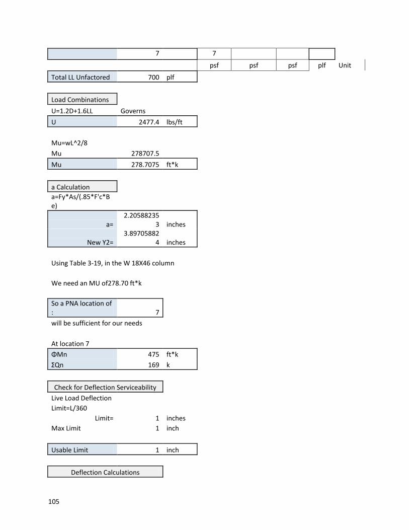
105
7 7
psf psf psf plf Unit
Total LL Unfactored 700 plf
Load Combinations U=1.2D+1.6LL Governs
U 2477.4 lbs/ft
Mu=wL^2/8 Mu 278707.5
Mu 278.7075 ft*k
a Calculation a=Fy*As/(.85*F'c*B
e)
a= 2.20588235
3 inches
New Y2= 3.89705882
4 inches
Using Table 3-19, in the W 18X46 column
We need an MU of278.70 ft*k
So a PNA location of : 7
will be sufficient for our needs
At location 7 ΦMn 475 ft*k
ΣQn 169 k
Check for Deflection Serviceability Live Load Deflection
Limit=L/360 Limit= 1 inches
Max Limit 1 inch
Usable Limit 1 inch
Deflection Calculations
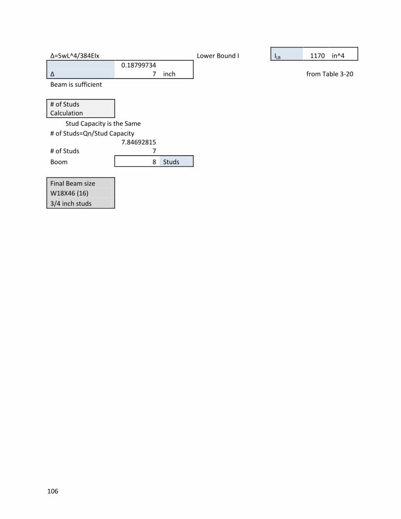
106
Δ=5wL^4/384EIx
Lower Bound I ILB 1170 in^4
Δ 0.18799734
7 inch
from Table 3-20
Beam is sufficient
# of Studs Calculation
Stud Capacity is the Same # of Studs=Qn/Stud Capacity
# of Studs 7.84692815
7 Boom 8 Studs
Final Beam size W18X46 (16) 3/4 inch studs

107
Fifth Floor Spandrel Girder Excel Spreadsheet
Scheme 1
DL Slab Services Ceiling Beam DL Wall Length 30
2121.25 60.41667 10 5 45 315 Spacing 15 lbs/ft
LL Load 31.5" girder spandrel 525 70 lbs/ft
PLASTIC CAPACITY CALCULATIONS Load Combinations
U=1.2D+1.6LL U 3385.5 lbs/ft
Mu=wL^2/8 Mu 380868.8 Mu 380.8688 ft/k
Zx required Zx =Mu/Φfy Zx 101.565 in^3
Off this we pick a W 21X55 with :
weight per foot 55 lbs/ft Zx
126 in^3
New DL calculations New DL=original DL + weight of beam
New DL 2176.25 lbs/ft
Live load is the same
New U U=1.2D+1.6LL
U 3451.5 lbs/ft
Mu=wL^2/8

108
Mu 388293.8 Mu 388.2938 ft/k
ΦMp=ΦZx*Fy ΦMp 472.5
the beam is sufficient
DEFLECTION CHECK
Case 1 LL only
Beam W 18X35
Deflection must be less than L/360 or 1" whichever is smaller Limit=L/360
Limit 1 inch So the deflection limit is the maximum, 1"
Δ=5wL^4/384EIx
Ix 1140 in^4 Δ 0.144708 inch
from Table 3.3
So we are okay
Case II Full DL + Half Live Limit=L/240
Limit 1.5 inch Δ=5wL^4/384EIx
Δ 1.314091 inch
So the current girder is sufficient by Deflection

109
Sixth Floor Spandrel Girder Excel Spreadsheet
Scheme 1
DL Slab Services Ceiling Beam DL Wall Length 30
2121.25 60.41667 10 5 45 315 Spacing 15 lbs/ft
LL Load 31.5" girder spandrel 1000 100 lbs/ft
PLASTIC CAPACITY CALCULATIONS Load Combinations
U=1.2D+1.6LL U 4145.5 lbs/ft
Mu=wL^2/8 Mu 466368.8 Mu 466.3688 ft/k
Zx required Zx =Mu/Φfy Zx 124.365 in^3
Off this we pick a W 24X55 with :
weight per foot 55 lbs/ft Zx
134 in^3
New DL calculations New DL=original DL + weight of beam
New DL 2176.25 lbs/ft
Live load is the same
New U U=1.2D+1.6LL
U 4211.5 lbs/ft
Mu=wL^2/8

110
Mu 473793.8 Mu 473.7938 ft/k
ΦMp=ΦZx*Fy ΦMp 502.5
the beam is sufficient
DEFLECTION CHECK
Case 1 LL only
Beam W 24X55
Deflection must be less than L/360 or 1" whichever is smaller Limit=L/360
Limit 1 inch So the deflection limit is the maximum, 1"
Δ=5wL^4/384EIx
Ix 1350 in^4 Δ 0.232759 inch
from Table 3.3
So we are okay
Case II Full DL + Half Live Limit=L/240
Limit 1.5 inch Δ=5wL^4/384EIx
Δ 1.220237 inch
So the current girder is sufficient by Deflection