Click to Reset! Click to Reset! Let’s reset it!. HOME NEXT EXIT.

May 24, 2012 ci-mb86r12-emerald-p-rev0-04
MB86R12 ’Emerald-P’
Rev0-04
May 24, 2012
Fujitsu Semiconductor Europe GmbH
Customer InformationKnown Chip Issues

2 ci-mb86r12-emerald-p-rev0-04 May 24, 2012
Fujitsu Semiconductor Europe GmbH MB86R12 ’Emerald-P’
History
Revision Date Author Description
0-04 24.05.2012 A. v. Treuberg Added R9641 and R9851
0-03 23.05.2012 A. v. Treuberg Replaced R4600 with R8470 due to new research results.
0-02 20.03.2012 A. v. Treuberg Added 3 issues R9239a/b, R9272 and ARM IP version information.
0-01 06.02.2012 R.v.Reitzenstein First release

May 24, 2012 ci-mb86r12-emerald-p-rev0-04 3
MB86R12 ’Emerald-P’ Fujitsu Semiconductor Europe GmbH
Customer Information
Table 1-2 shows a list of all deviations or functional problems of the MB86R12 ’Emerald-P’ known at therelease date of this CI-document. Each issue has an unique ID, based on our tracking system.
For detailed description of each issue, please click on the respective issue ID.
Table 1-1: MB86R12 ‘Emerald-P’ Devices
Device: ES1 ES2 ES3
Date Code (DC): 1132 1150 TBD
Chip ID (CCID): 865212F1 815212F2 TBD
Table 1-2: Overview
ID Unit Item Effected DevicesDC: available beginning with date code xxxxX: effected-: not effected
ES1 ES2 ES3
ARM CPU ARM Cortex-A9/PL310/PTM Errata X X X
BN1214 APIX APIX2_link (Timeout interrupts) X - -
BN1292 APIX-TX APIX PLLgood needs Rx X X X
BN1294 APIX Bit error on APIX TX X - -
R7720 HS_SPI RX Data may be corrupted X X X
R7863 Video Capture Unit Capture 1920 width limitation X - -
R8470 Ethernet Ethernet GMII mode not functional X X X
R9971 Display Controller Read error of L2AM-bit X - -
R8709 GDC Controller Misalignment of Y component X - -
R9047 External Bus Controller CS2 in NAND Flash mode X X X
R9087 Clock Reset Generator Software reset X X X
R9109 Reset Debug Reset X X X
R9181 USART USART Loopback X X X
BL6263 HS_SPI RX-Data lost X X X
R9239a 3D Wrong 1/W and varying variables of a fragment X X -
R9239b 3D Wrong Z, 1/W, and fragment Varying in MSAA mode X X -
R9272 CPU CPU - Connection with a JTAG SW debugger
X X -
R9641 DISP1 Timing specification change for RGB mode X X -
R9851 Ethernet Ethernet - Checksum and IPv6 error X X X

4 ci-mb86r12-emerald-p-ARM-rev0-04 March 19, 2012
Fujitsu Semiconductor Europe GmbH MB86R12 ’Emerald-P’
Table 1-3: CPU - ARM Cortex-A9/PL310/PTM Errata
ARM The versions of the ARM Cortex-A9/PL310/PTM components implementedin all versions of the MB86R12 ‘Emerald-P’ device are listed below so thatany relevant errata for the ARM IPs can be identified (using the ARMsupport website).
Overview
Unitname CPU
Detail
The following IPs are implemented:
Cortex-A9: r3p0-50rel0
PL310(L2 cache): r3p2-00rel0
PTM: r1p0-00rel0
Workaround
Please refer to the ARM support website.
Status
Effects all ES and CS versions of the device.

May 24, 2012 ci-mb86r12-emerald-p#1214-rev0-04 5
MB86R12 ’Emerald-P’ Fujitsu Semiconductor Europe GmbH
Table 1-4: APIX2_link (Timeout interrupts)
BN1214 APIX2_link Timeout interrupts Overview
Unit APIX
Detail
If the following interrupts:
APIX RX InStauts1.status_timeout (RX Register Int[0|1]Enable1 Bit 28)
APIX TX0,1,2 InStatus2.status_timeout (APIX TX0,1,2 Register Int[0|1]Enable2 Bit 4)
APIX TX0,1,2 InStatus2.debug_timeout (APIX TX0,1,2 Register Int[0|1]Enable2 Bit 5)
are enabled and a read to an arbitrary APIX register is performed, the above mentionedinterrupts are continuously asserted, even if no timeout is happening.
Workaround
Do not enable the above mentioned interrupts. Make sure, that all APIX clocks areenabled. This prevents the timeout causing abort of read access. Then, read accessesdeliver always valid read results.
Additional Information: The above mentioned interrupts have the intention to inform anapplication about a timeout-aborted read access. In this case read results are not validand should be discarded.
Status
Fixed in ES2.

6 ci-mb86r12-emerald-p#1292-rev0-04 May 24, 2012
Fujitsu Semiconductor Europe GmbH MB86R12 ’Emerald-P’
Table 1-5: APIX PLLgood needs Rx
BN1292 APIX PLLgood signal requires APIX RX to be powered Overview
Unit name APIX
Detail
PLLgood signal is active only if RX is powered on (rx_power_on = 1) and RX cfg_valid = 1.
If rx_power_on=0 and cfg_valid = 1 there is no clock and PLL_good retains its last state.
Workaround
Enable Rx
Status
Will not be fixed.

May 24, 2012 ci-mb86r12-emerald-p#1294-rev0-04 7
MB86R12 ’Emerald-P’ Fujitsu Semiconductor Europe GmbH
Table 1-6: Bit error on APIX TX
BN1294 Bit error on APIX TX Overview
Unit name APIX TX
Detail
Bit errors will occur on APIX TX when the device is subject to a high temperature and theAPIX analog power supply (VDDA) is low. The issue can be detected when VDDA islower than VDDI.
The critical VDDA supply voltage level is sample-dependent.
Workaround
VDDA should be higher than VDDI.
Status
Fixed in ES2.

8 ci-mb86r12-emerald-p#7720-rev0-04 May 24, 2012
Fujitsu Semiconductor Europe GmbH MB86R12 ’Emerald-P’
Table 1-7: HS_SPI (RX Data may be corrupted)
R7720 RX Data may be corrupted Overview
Unit name HS_SPI
Detail
If the RX Fifo becomes full
One of the following phenomenons may occur
RX Data is lost
Wrong RX Data i.e. sampled at wrong moment
Transfer is stopped too soon in TX-and-RX protocol, i.e. when STOP is set, data is not transmitted/received anymore after RX FIFO gets full
Transfer is stopped too soon, when byte counter is used, i.e. less data than configured by the byte counter is transferred
Workaround
Do not let the RX-FIFO become full (use low RX-FIFO threshold and low interrupt/DMAlatency time)
Status
Will not be fixed.

May 24, 2012 ci-mb86r12-emerald-p#7863-rev0-04 9
MB86R12 ’Emerald-P’ Fujitsu Semiconductor Europe GmbH
Table 1-8: Video Capture Unit - Capture 1920 width limitation
R7863 Limitation when using Capture Unit0 with length > 1280 pixels Overview
Unit name Video Capture
Detail
When Capture unit 0 is used, Scaling ratio is not 1:1, and width of capture result is largerthan 1280 pixel.
It is assumed that capture unit 0 accept picture width up to 1920 pixel, but error data likenoise appears at right and left side of output picture if it is wider than 1280 pixel.
Workaround
Limit capture usage to 1:1 scaling if output picture is larger than 1280
Status
Fixed in ES2.

10 ci-mb86r12-emerald-p#8470-rev0-04 May 24, 2012
Fujitsu Semiconductor Europe GmbH MB86R12 ’Emerald-P’
Table 1-9: Ethernet (GMII Interface)
R8470 Ethernet GMII mode: this mode is not functional Overview
Unit name Ethernet
Detail
The GMII mode of the Ethernet MAC can not be used for 1GBit network communication.However, Ethernet using the MII or RMII is fully functional at 10Mbit and 100MBit.
Workaround
A workaround is not available.
Status
Will not be fixed.
May 24, 2012 ci-mb86r12-emerald-p#9971-rev0-04 11
MB86R12 ’Emerald-P’ Fujitsu Semiconductor Europe GmbH
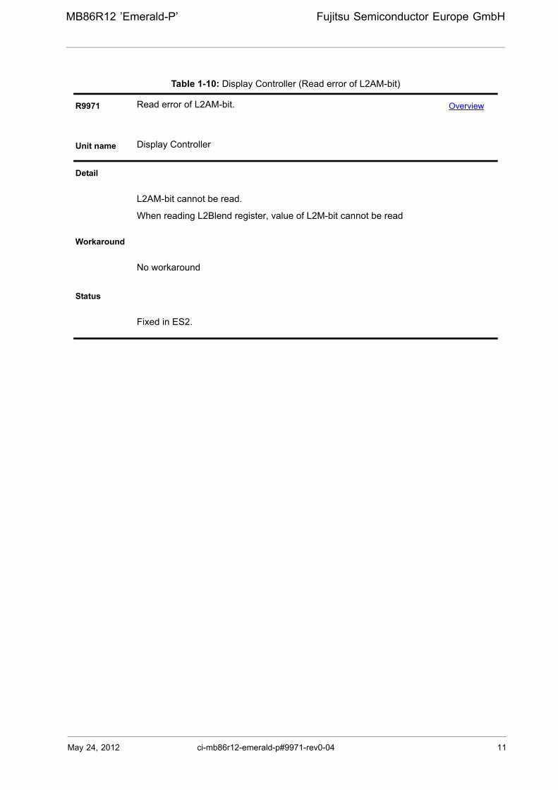
Table 1-10: Display Controller (Read error of L2AM-bit)
R9971 Read error of L2AM-bit. Overview
Unit name Display Controller
Detail
L2AM-bit cannot be read.
When reading L2Blend register, value of L2M-bit cannot be read
Workaround
No workaround
Status
Fixed in ES2.

12 ci-mb86r12-emerald-p#8709-rev0-04 May 24, 2012
Fujitsu Semiconductor Europe GmbH MB86R12 ’Emerald-P’
Table 1-11: GDC Controller (Misalignment of Y component)
R8709 Misalignment of Y component Overview
Unit name Graphic Display Controller-Display YUV 656 output
Detail
If YCbCr output is used:
Y-component is shifted left by one pixel.
Left edge is missing.
Right edge is repeated twice.
Workaround
1. If YCbCr output is used as a composite analog output, shift thehorizontal line by one pixel.
2. No change in display setup, but avoid left and right edge for pictureoutput.
Status
Fixed for ES2.

May 24, 2012 ci-mb86r12-emerald-p#9047-rev0-04 13
MB86R12 ’Emerald-P’ Fujitsu Semiconductor Europe GmbH
Table 1-12: External Bus Controller (CS2 in NAND Flash mode)
R9047 CS2 in NAND Flash mode Overview
Unit name External Bus Controller
Detail
CS2 is not masked. Therefore, conflict of data or hang-up may happen
CS2 is NAND mode (Mode register2 NAND bit is set to '1') and GLBCTL.CS_MOD of CCNT register is set to '1'.
Workaround
Please do not use CS2 in NAND mode.
If you want to use CS2 NAND mode, please set GLBCTL.CS_MOD=0.
Status
Will not be fixed.

14 ci-mb86r12-emerald-p#9087-rev0-04 May 24, 2012
Fujitsu Semiconductor Europe GmbH MB86R12 ’Emerald-P’
Table 1-13: CRG - SW Reset may fail
R9087 SW Reset may fail Overview
Unit name Clock Reset Controller
Detail
SW Reset may fail when CRG_P is used for clock supply to interconnect and all modulesexcept Display, CAN, DDRC, UART, and USART.
Workaround
1. Do not use SW Reset.
2. If you need to use SW reset use CRG_S for clock supply ofinterconnect and all modules except Display, DDR MemoryController, CAN, UART, and USART + disable SSCG function, ifunmodulated clock is necessary.
Status
Will not be fixed.

May 24, 2012 ci-mb86r12-emerald-p#9109-rev0-04 15
MB86R12 ’Emerald-P’ Fujitsu Semiconductor Europe GmbH
Table 1-14: Reset (Debug Reset)
R9109 Debug Reset Overview
Unit name Reset
Detail
When software reset is asserted a debug reset might occur also under followingcondition:
1. Tb depends on CRRSC.SRSTMODE(CRG_S Register) setting.
2. In case 400MHz(max frequency) and SRSTMODE==15(default setting),Tbmax is 384*2.5(ns)=960(ns)
Workaround
1. Please set CRRSC.SWRSTM==1 and CRRSC.WDRSTM==1.
2. Please pull-up XSRST (for example,5Kohm) outside LSI and stand up less thanTbmax cycles.
Status
Will not be fixed.
XSRST
Ta Tb
SRSTMODE Ta Tbmax
0 8 cycles 16 cycles1 12 cycles 16 cycles2 16 cycles 16 cycles3 24 cycles 16 cycles4 32 cycles 16 cycles5 48 cycles 16 cycles6 64 cycles 16 cycles7 96 cycles 24 cycles8 128 cycles 32 cycles9 192 cycles 48 cycles10 256 cycles 64 cycles11 384 cycles 96 cycles12 512 cycles 128 cycles13 768 cycles 192 cycles14 1024 cycles 256 cycles15(default) 1536 cycles 384 cycles

16 ci-mb86r12-emerald-p#9181-rev0-04 May 24, 2012
Fujitsu Semiconductor Europe GmbH MB86R12 ’Emerald-P’
Table 1-15: USART - Loopback
R9181 In operation mode 3, when you use Loopback, LIN communication does notwork well.
Overview
Unit name USART
Detail
In order to receive Sync Field to Frame-ID continuously, please set RXE==0 untildetecting Sync Field.Frame-ID is detected by automatic header reception. Finally pleaseset RXE==1.
When you use USART Loopback, hardware sets RXE==1. Therefore, frame-ID is notdetected. and LIN communication does not work well.
Workaround
Please avoid to use Loopback in operation mode3 by the setting of SMRn.MD[1:0]==3and EFERHn.INTLBEN==1.
Status
Will not be fixed.

May 24, 2012 ci-mb86r12-emerald-p#6263-rev0-04 17
MB86R12 ’Emerald-P’ Fujitsu Semiconductor Europe GmbH
Table 1-16: HS_SPI - RXDATA lost
BL6263 RX Data may be corrupted Overview
Unit name HS_SPI
Detail
HS_SPI lost the received data.
The data of RXSHIFTER does not transfer to RXFIFO.
Workaround
Read an additional byte.
Status
Will not be fixed.
Fujitsu Semiconductor Europe GmbH MB86R12 ’Emerald-P’
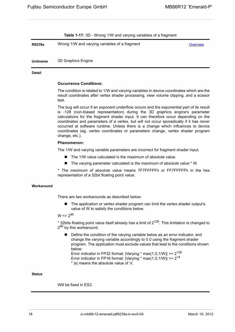
Table 1-17: 3D - Wrong 1/W and varying variables of a fragment
R9239a Wrong 1/W and varying variables of a fragment Overview
Unitname 3D Graphics Engine
Detail
Occurrence Conditions:
The condition is related to 1/W and varying variables in device coordinates which are theresult coordinates after vertex shader processing, view volume clipping, and a scissortest.
The bug will occur if an exponent underflow occurs and the exponential part of its resultis -128 (non-biased representation) during the 3D graphics engine's parametercalculations for the fragment shader input. It can therefore occur depending on thecoordinates and parameters of a vertex, but will not occur sporadically if it has neveroccurred at software runtime. Unless there is a change which influences to devicecoordinates (eg. vertex coordinates or parameters change, vertex shader programchange, etc.).
Phenomenon:
The 1/W and varying variable parameters are incorrect for fragment shader input.
The 1/W value calculated is the maximum of absolute value.
The varying parameter calculated is the maximum of absolute value * W.
* The maximum of absolute value means 7F7FFFFFh or FF7FFFFFh in the hexrepresentation of a 32bit floating point value.
Workaround
There are two workarounds as described below:
The application or vertex shader program can limit the vertex shader output’s value of W to satisfy the conditions below.
W <= 290
* 32bits floating point value itself already has a limit of 2128. This limitation is changed to290 by this workaround.
Define the condition of the varying variable below as an error indicator, and change the varying variable accordingly to 0.0 using the fragment shader program. The application must exclude values that lead to the conditions shown below:Error indicator in FP32 format: |Varying * max(1.0,1/W)| >= 2126
Error indicator in FP16 format: |Varying * max(1.0,1/W)| >= 214
* |x| means the absolute value of 'x'.
Status
Will be fixed in ES3.
18 ci-mb86r12-emerald-p#9239a-b-rev0-04 March 19, 2012
MB86R12 ’Emerald-P’ Fujitsu Semiconductor Europe GmbH
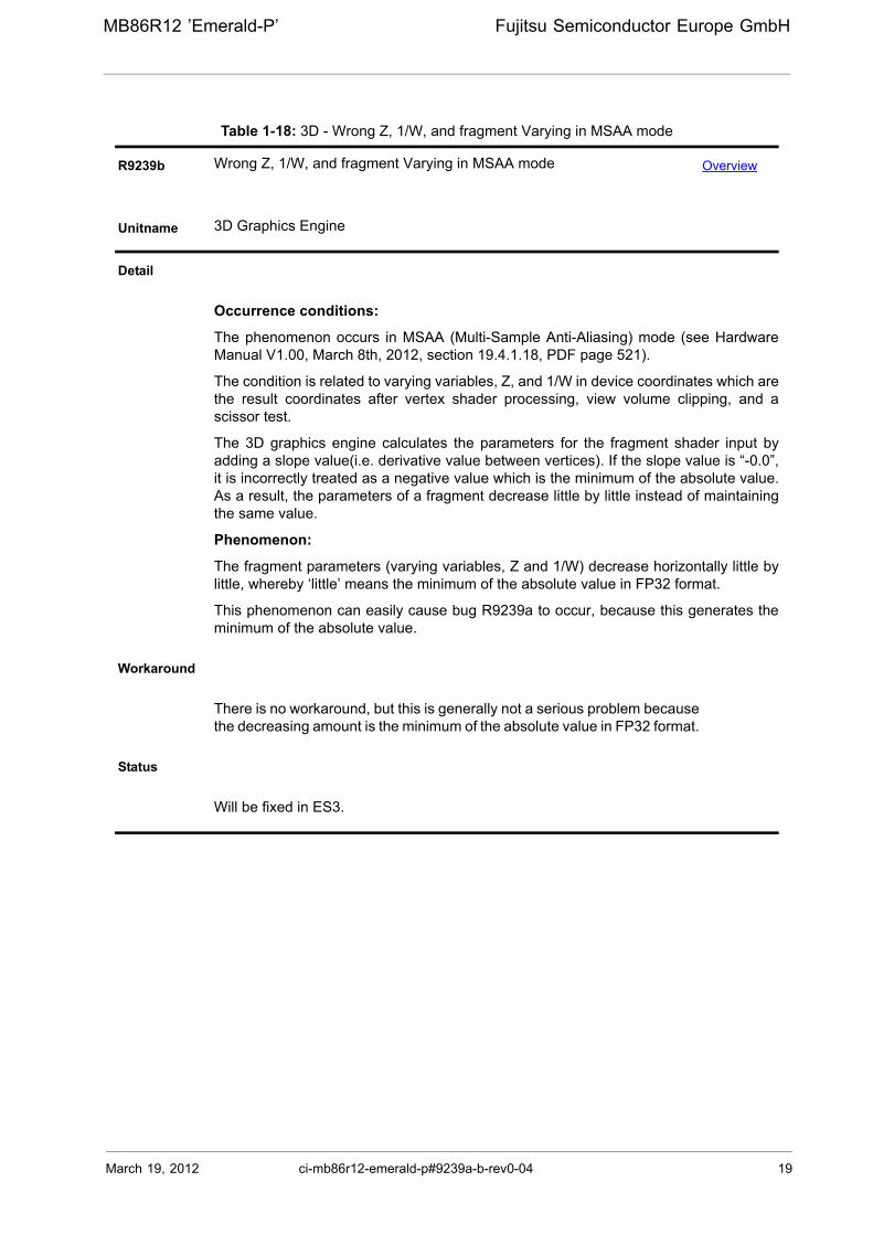
Table 1-18: 3D - Wrong Z, 1/W, and fragment Varying in MSAA mode
R9239b Wrong Z, 1/W, and fragment Varying in MSAA mode Overview
Unitname 3D Graphics Engine
Detail
Occurrence conditions:
The phenomenon occurs in MSAA (Multi-Sample Anti-Aliasing) mode (see HardwareManual V1.00, March 8th, 2012, section 19.4.1.18, PDF page 521).
The condition is related to varying variables, Z, and 1/W in device coordinates which arethe result coordinates after vertex shader processing, view volume clipping, and ascissor test.
The 3D graphics engine calculates the parameters for the fragment shader input byadding a slope value(i.e. derivative value between vertices). If the slope value is “-0.0”,it is incorrectly treated as a negative value which is the minimum of the absolute value.As a result, the parameters of a fragment decrease little by little instead of maintainingthe same value.
Phenomenon:
The fragment parameters (varying variables, Z and 1/W) decrease horizontally little bylittle, whereby ‘little’ means the minimum of the absolute value in FP32 format.
This phenomenon can easily cause bug R9239a to occur, because this generates theminimum of the absolute value.
Workaround
There is no workaround, but this is generally not a serious problem becausethe decreasing amount is the minimum of the absolute value in FP32 format.
Status
Will be fixed in ES3.
March 19, 2012 ci-mb86r12-emerald-p#9239a-b-rev0-04 19
20 ci-mb86r12-emerald-p#9272-rev0-04 March 19, 2012
Fujitsu Semiconductor Europe GmbH MB86R12 ’Emerald-P’
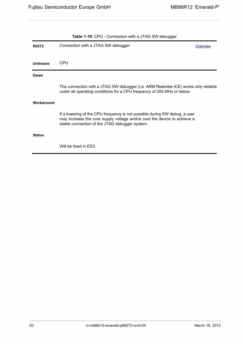
Table 1-19: CPU - Connection with a JTAG SW debugger
R9272 Connection with a JTAG SW debugger Overview
Unitname CPU
Detail
The connection with a JTAG SW debugger (i.e. ARM Realview ICE) works only reliableunder all operating conditions for a CPU frequency of 200 MHz or below.
Workaround
If a lowering of the CPU frequency is not possible during SW debug, a usermay increase the core supply voltage and/or cool the device to achieve astable connection of the JTAG debugger system.
Status
Will be fixed in ES3.

March 19, 2012 ci-mb86r12-emerald-p#9641-rev0-04 21
MB86R12 ’Emerald-P’ Fujitsu Semiconductor Europe GmbH
Table 1-20: DISP1 - Timing specification change for RGB mode
R9641 Timing specification change for RGB mode Overview
Unitname DISP1
Detail
The actual minimum delay time for the RGB output of DISP1is larger than specified inthe in the AC Characteristics, meaning that the data hold time for an external device ininsufficient. This results in an imprecise data transfer, reducing picture quality.Theproblem is limited to the following signals: DISP1[R|G|B]7:0. The following table showsthe correct values for the effected ES versions.
Workaround
Two solutions can be used to avoid the problem.
1. Change the timing of DISP1CLKOUse the DCLKDEL and DCKINV fields of the DCLK Config register to modify theoutput timing.
2. Use dual display mode to create a new data hold timingDual display mode can be used to create a new data hold timing. If this mode isused to output the same layer to two screens, the RGB output value does notchange during the transition from the first screen to the second screen,effectively creating a new data hold timing.
Status
Will be fixed in ES3.
Table 1-21: ES1 Tdrgb Timings
Signal Symbol Description Mode Min. Unit
DISP1R[7:0]DISP1G[7:0]DISP1B[7:0]
TdrgbRGB output delay time
Single edge -1.8nsDual edge -1.8
Dual pixel -1.8
Table 1-22: ES2 Tdrgb Timings
Signal Symbol Description Mode Min. Unit
DISP1R[7:0]DISP1G[7:0]DISP1B[7:0]
TdrgbRGB output delay time
Single edge -1.5
nsDual edge -1.5
Delay -1.2Dual pixel -1.5

22 ci-mb86r12-emerald-p#9851-rev0-04 March 19, 2012
Fujitsu Semiconductor Europe GmbH MB86R12 ’Emerald-P’
Table 1-23: Ethernet - Checksum and IPv6 error
R9851 Ethernet - Checksum and IPv6 error Overview
Unitname Ethernet
Detail
The Ethernet unit mis-recognizes the checksum field and discards a valid frame if itreceives an IPv6 frame with an Authentication Header.
Workaround
Do not use the checksum function when the Ethernet unit could receive anIPv6 frame with an Authentication Header.
Status
Will not be fixed.

Fujitsu Semiconductor Europe GmbH mb86r12-emerald-p
Warranty and Disclaimer
To the maximum extent permitted by applicable law, Fujitsu Microelectronics Europe GmbH restricts itswarranties and its liability for all products delivered free of charge (eg. software include or headerfiles, application examples, target boards, evaluation boards, engineering samples of IC’s etc.), itsperformance and any consequential damages, on the use of the Product in accordance with (i) the termsof the License Agreement and the Sale and Purchase Agreement under which agreements the Producthas been delivered, (ii) the technical descriptions and (iii) all accompanying written materials. Inaddition, to the maximum extent permitted by applicable law, Fujitsu Microelectronics Europe GmbHdisclaims all warranties and liabilities for the performance of the Product and any consequentialdamages in cases of unauthorized decompiling and/or reverse engineering and/or disassembling. Note,all these products are intended and must only be used in an evaluation laboratory environment.
1. Fujitsu Microelectronics Europe GmbH warrants that the Product will perform substantially inaccordance with the accompanying written materials for a period of 90 days form the date ofreceipt by the customer. Concerning the hardware components of the Product, FujitsuMicroelectronics Europe GmbH warrants that the Product will be free from defects in materialand workmanship under use and service as specified in the accompanying written materials fora duration of 1 year from the date of receipt by the customer.
2. Should a Product turn out to be defect, Fujitsu Microelectronics Europe GmbH´s entire liabilityand the customer´s exclusive remedy shall be, at Fujitsu Microelectronics Europe GmbH´s solediscretion, either return of the purchase price and the license fee, or replacement of the Productor parts thereof, if the Product is returned to Fujitsu Microelectronics Europe GmbH in originalpacking and without further defects resulting from the customer´s use or the transport. However,this warranty is excluded if the defect has resulted from an accident not attributable to FujitsuMicroelectronics Europe GmbH, or abuse or misapplication attributable to the customer or anyother third party not relating to Fujitsu Microelectronics Europe GmbH.
3. To the maximum extent permitted by applicable law Fujitsu Microelectronics Europe GmbHdisclaims all other warranties, whether expressed or implied, in particular, but not limited to,warranties of merchantability and fitness for a particular purpose for which the Product is notdesignated.
4. To the maximum extent permitted by applicable law, Fujitsu Microelectronics Europe GmbH´sand its suppliers´ liability is restricted to intention and gross negligence.
NO LIABILITY FOR CONSEQUENTIAL DAMAGES
To the maximum extent permitted by applicable law, in no event shall Fujitsu MicroelectronicsEurope GmbH and its suppliers be liable for any damages whatsoever (including but withoutlimitation, consequential and/or indirect damages for personal injury, assets of substantialvalue, loss of profits, interruption of business operation, loss of information, or any othermonetary or pecuniary loss) arising from the use of the Product.
Should one of the above stipulations be or become invalid and/or unenforceable, the remainingstipulations shall stay in full effect
Fujitsu Semiconductor Europe GmbH - Graphics Competence CenterForstenrieder Str. 10, D - 82061 Neuried Germany
Tel: +49 (89) 218 938 - 0Fax: +49 (89) 218 938 - 401
http://emea.fujitsu.com/semiconductor