Skull. Mandible Skull Mandible clavicle Skull Mandible clavicle humerus.
Upload
scott-wilkinsCategory
view
220download
1
MATLAB Mandible Tracing & Calculations Program
Documentation by Antonis VakisSupplemental Material for:
PHYLOGENY, SCALING, AND THE GENERATION OF EXTREME FORCES IN TRAP-JAW ANTS
JOSEPH C. SPAGNA, ANTONIS I. VAKIS, CHRIS A. SCHMIDT, SHEILA N. PATEK,
XUDONG ZHANG, and ANDREW V. SUAREZ

So far, all captures have been saved as sequential
TIFF files
The images, within their original folders (e.g.
093004as4), need to be placed in a directory called
'Images,' located in the current working directory
First, run the tracing program

The folder name is saved as a parameter called: filename

Specify the number of frames per second (fps)

Specify the width of video in pixels (width)

Specify the height of video in pixels (height)

Specify the image resolution in dots per inch (dpi)

Viewing the image thumbnails, select the range of images over which the full motion of the mandibles is
captured

Viewing the image thumbnails, select the range of images over which the full motion of the mandibles is
captured

Viewing the image thumbnails, select the range of images over which the full motion of the mandibles is
captured
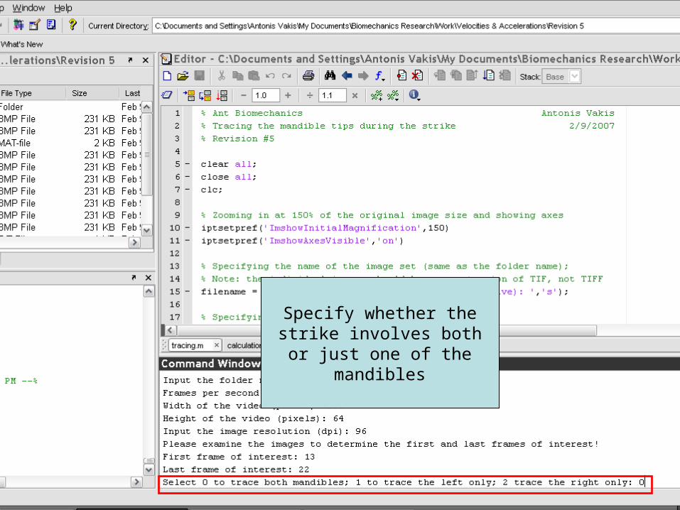
Specify whether the strike involves both or just one of
the mandibles
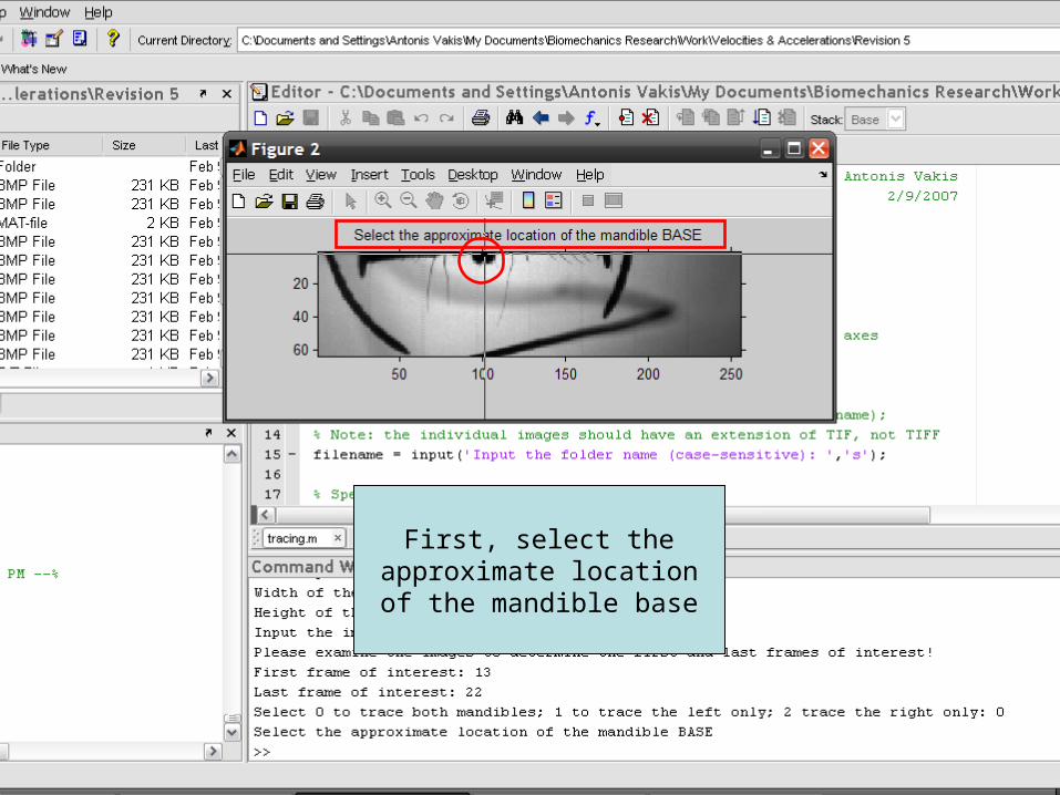
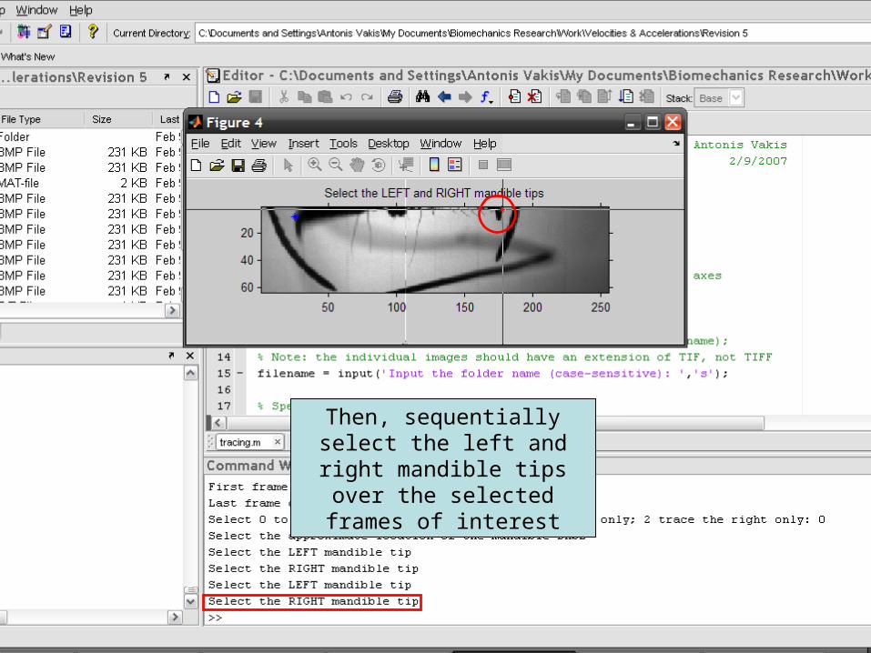
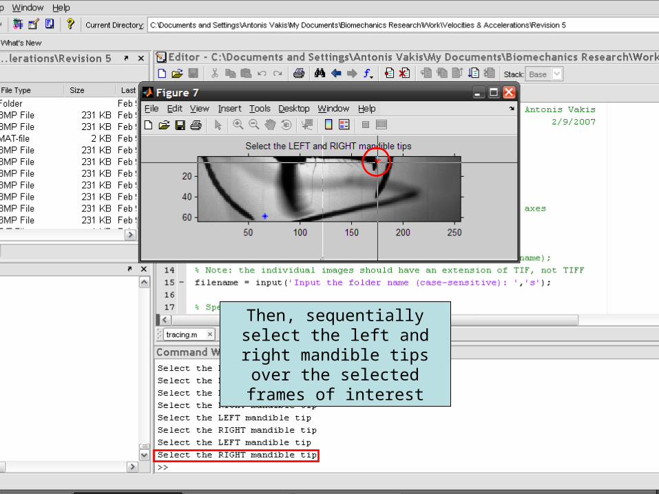
First, select the approximate location of the mandible base

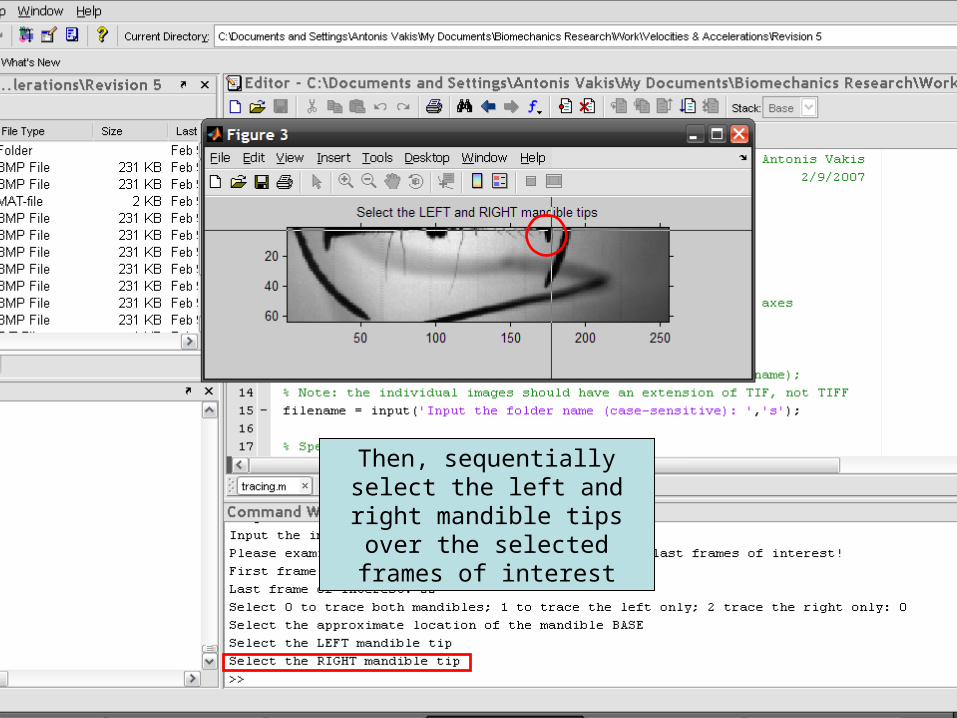
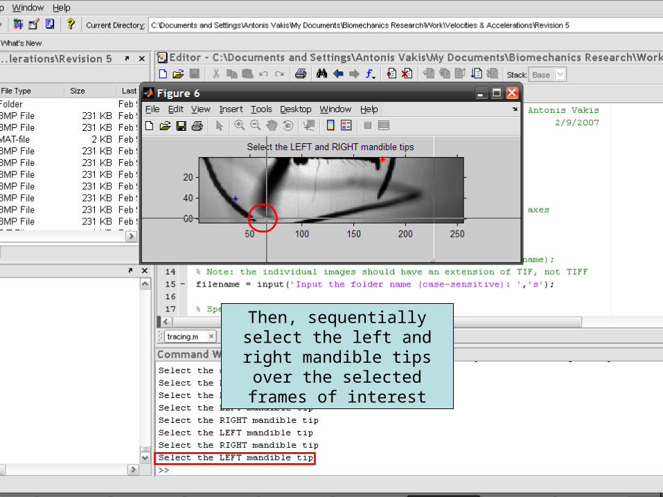
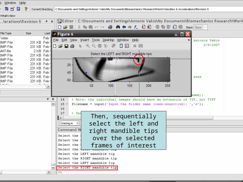
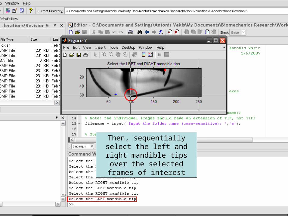
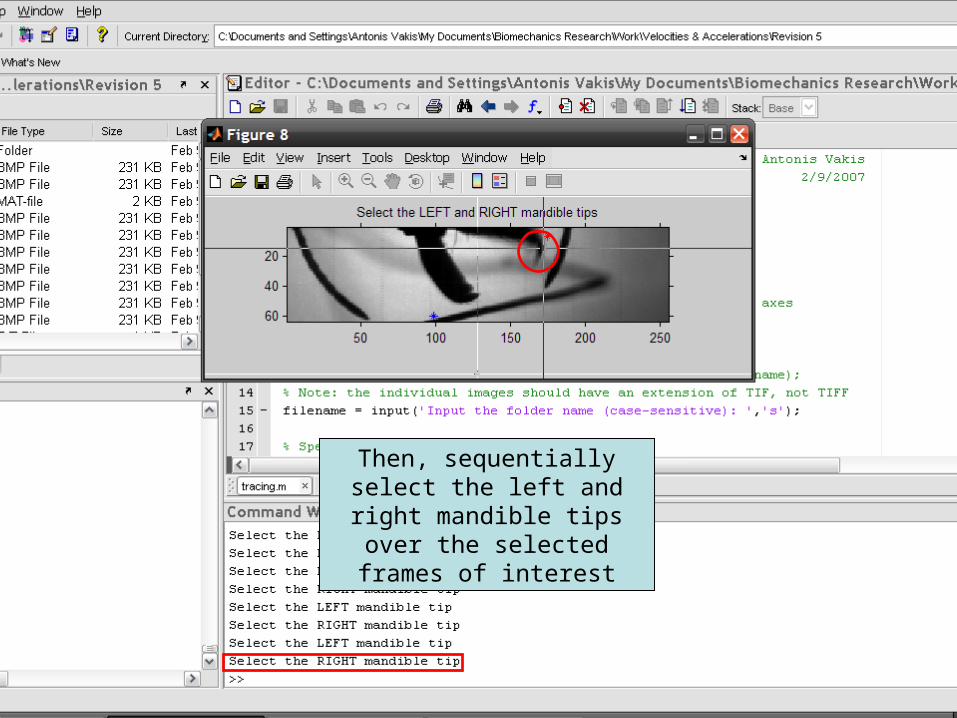
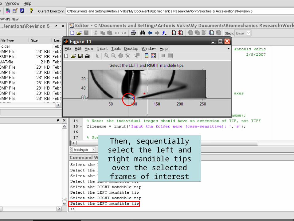
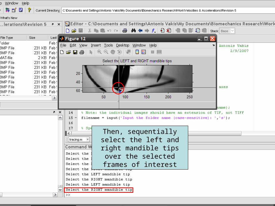
Then, sequentially select the left and right mandible tips over the selected frames of
interest
Then, sequentially select the left and right mandible tips over the selected frames of
interest

Then, sequentially select the left and right mandible tips over the selected frames of
interest
Then, sequentially select the left and right mandible tips over the selected frames of
interest

Then, sequentially select the left and right mandible tips over the selected frames of
interest

Then, sequentially select the left and right mandible tips over the selected frames of
interest
Then, sequentially select the left and right mandible tips over the selected frames of
interest
Then, sequentially select the left and right mandible tips over the selected frames of
interest
Then, sequentially select the left and right mandible tips over the selected frames of
interest
Then, sequentially select the left and right mandible tips over the selected frames of
interest

Then, sequentially select the left and right mandible tips over the selected frames of
interest
Then, sequentially select the left and right mandible tips over the selected frames of
interest

Then, sequentially select the left and right mandible tips over the selected frames of
interest

Then, sequentially select the left and right mandible tips over the selected frames of
interest

Then, sequentially select the left and right mandible tips over the selected frames of
interest

Then, sequentially select the left and right mandible tips over the selected frames of
interest
Then, sequentially select the left and right mandible tips over the selected frames of
interest

Then, sequentially select the left and right mandible tips over the selected frames of
interest

Then, sequentially select the left and right mandible tips over the selected frames of
interest
Then, sequentially select the left and right mandible tips over the selected frames of
interest

Finally, reselect the approximate location of the mandible base; an
average mandible position will be used for the calculations

Magnification parameter: zoom
Default value = 10x
In the case where it is unknown, the magnification can be calculated from the average recorded mandible
length for each species
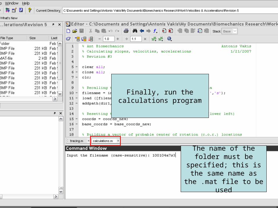
Finally, run the calculations program
The name of the folder must be specified; this is
the same name as the .mat file to be used

Calculations: Rcrude
Mandible base, A (x1, y1)
Closed position
B (x2, y2)
Rcrude
2122
12_ yyxxleftRcrude
2
__ rightRcrudeleftRcrudeRcrude

Calculations: Grid
• Select number of grid points/ possible positions of centers of rotatione.g. 40 intervals, 41 x 41 = 1,681 grid points
• Create grid centered around the calculated mandible base locationcor_values_min_x = base_coords(1,1) – Rcrude
cor_values_max_x = base_coords(1,1) + Rcrude
cor_values_min_y = base_coords(1,2) – Rcrude
cor_values_max_y = base_coords(1,2) + Rcrude

Calculations: Grid
• Create a matrix with grid coordinates using values calculated for the minima and maxima in the x and y directions, as well as the interval
• Reshape the resulting 41 x 41 x 2 matrix to a matrix of size 1681 x 2 (cor_values matrix)

Calculations: Rvalues
• Having established the number of iterations for the left and right centers of rotation locations, specify the number of iterations for each mandible radius (values, e.g. 200)
• Specify:Rmin = Rcrude – Rcrude/2 (50% smaller)Rmax = Rcrude + Rcrude/2 (50% larger)
• Rvalues = linspace(Rmin,Rmax,values)

Calculations: Iterations
• Using nested for loops, iterate the values of x, y and R for the left and right mandibles
for # of possible radius values (values) (p)
for # of elements (41 x 41 = 1,681) (k)
for # of frames (e.g. 8) (i)
to get the RMS_error for each mandible
Calculations: RMSerror
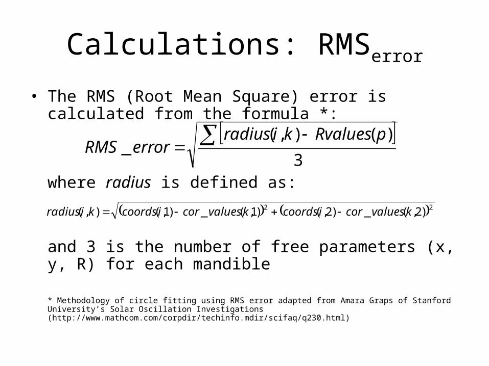
• The RMS (Root Mean Square) error is calculated from the formula *:
where radius is defined as:
and 3 is the number of free parameters (x, y, R) for each mandible
* Methodology of circle fitting using RMS error adapted from Amara Graps of Stanford University’s Solar Oscillation Investigations (http://www.mathcom.com/corpdir/techinfo.mdir/scifaq/q230.html)
3
)(),(_
pRvalueskiradius
errorRMS
22 )2,(_)2,()1,(_)1,(),( kvaluescoricoordskvaluescoricoordskiradius
Calculations: Minimum RMSerror
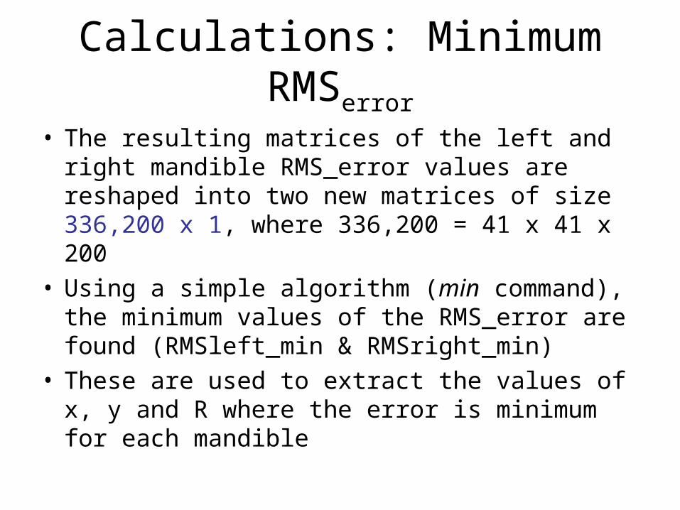
• The resulting matrices of the left and right mandible RMS_error values are reshaped into two new matrices of size 336,200 x 1, where 336,200 = 41 x 41 x 200
• Using a simple algorithm (min command), the minimum values of the RMS_error are found (RMSleft_min & RMSright_min)
• These are used to extract the values of x, y and R where the error is minimum for each mandible

Calculations: RMSerror plots
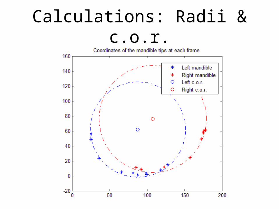
Calculations: Radii & c.o.r.

Calculations: ω and α
• To calculate the angular velocities and accelerations use the following formulae, based on the difference of the slopes in each frame:
θ(i) = atan [coords(i,2) – x0y0(1,2)] [coords(i,1) – x0y0(1,1)]
ω(i) = [θ(i+1) – θ(i)]*fps (rad/s)α(j) = [ω(j+1) – ω(j)]*fps (rad/s/s)
where θ(i) is the slope of each frame, ω(i) is the ang. velocity, α(j) is the ang. acceleration, and fps are the frames per sec. For n frames, there are n-1 velocity and n-2 acceleration values
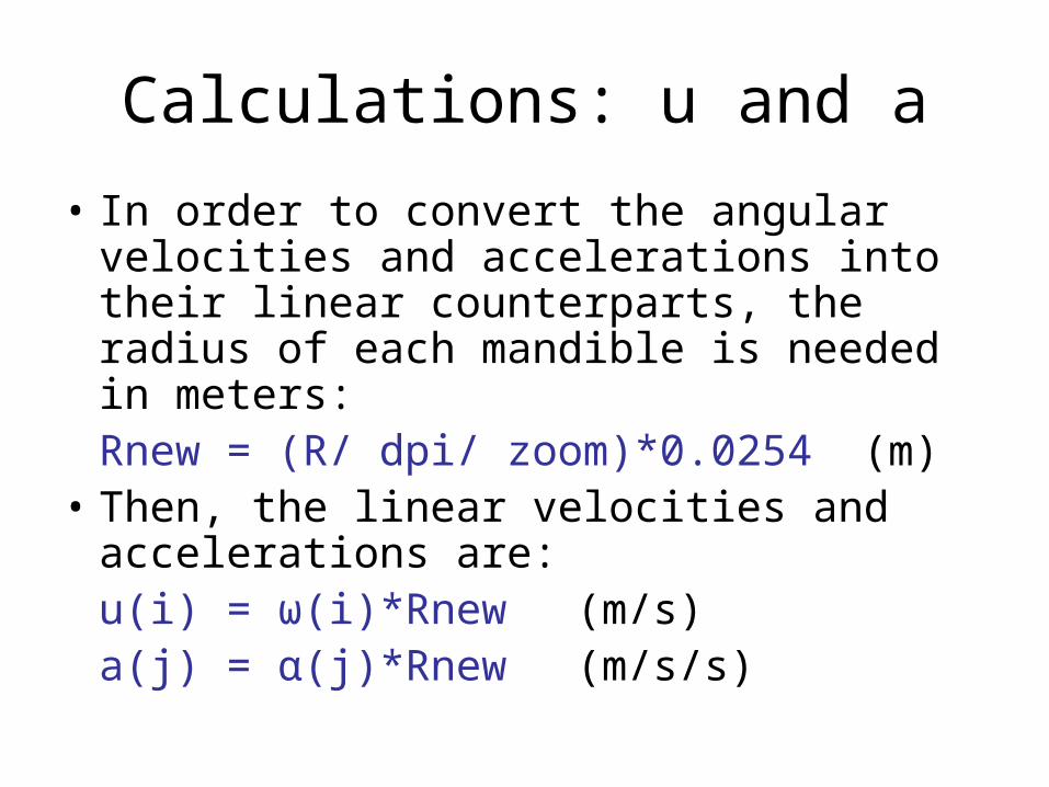
Calculations: u and a
• In order to convert the angular velocities and accelerations into their linear counterparts, the radius of each mandible is needed in meters:Rnew = (R/ dpi/ zoom)*0.0254(m)
• Then, the linear velocities and accelerations are:
u(i) = ω(i)*Rnew (m/s)a(j) = α(j)*Rnew (m/s/s)

Calculations: Velocity Plots
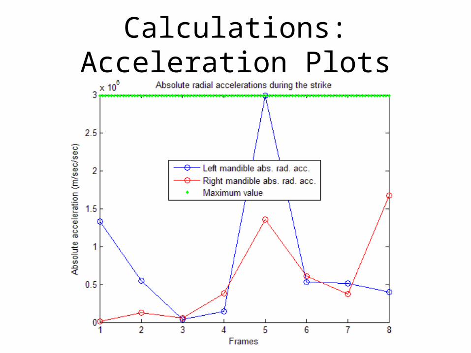
Calculations: Acceleration Plots

Output of Calculations Program


![[Antonis Simintiras] International Marketing Revie(BookZZ.org)](https://static.fdocuments.us/doc/165x107/577cc0c21a28aba7119102b4/antonis-simintiras-international-marketing-reviebookzzorg.jpg)


![Antonis Liakos-Canon of European History[1]](https://static.fdocuments.us/doc/165x107/55cf8c505503462b138b59d7/antonis-liakos-canon-of-european-history1.jpg)