Material Aspects of High-Temperature Automotive Product...
34
External Use TM Material Aspects of High Temperature Automotive Product Packaging FTF-SDS-F0025 APR.2014 Tu Anh Tran | C55 Packaging Technical Lead, Packaging Technology Development
-
Upload
duonghuong -
Category
Documents
-
view
223 -
download
0
Transcript of Material Aspects of High-Temperature Automotive Product...
External Use
TM
Material Aspects of High
Temperature Automotive
Product Packaging
FTF-SDS-F0025
A P R . 2 0 1 4
Tu Anh Tran | C55 Packaging Technical Lead,
Packaging Technology Development
TM
External Use 1
Session Introduction
• This presentation will provide a review of the challenges imposed
by the high temperature applications in the modern automotive
environment.
• Discuss the changes in packaging materials and processes
required to meet the new requirements.
• Discuss Freescale’s C55FG packaging solution satisfying AEC
Grade 0 packaging reliability requirements.
• Presented by Tu Anh Tran, C55 Packaging Tech Lead, Package
Technology Development.

TM
External Use 2
Session Objectives
After completing this session you will be able to:
• Understand the landscape of the modern automotive environment
• Compare how new packaging requirements differ from current
requirements in automotive applications
• Describe C55FG LQFP-EP package material and process changes
necessary to meet and exceed the requirements
TM
External Use 3
Agenda
• New automotive environments
• Implications to packaging
• Challenges and resolutions in:
− Wafer dicing
− Die attaching
− Wire bonding
− Molding
• Session summary
TM
External Use 4
New Automotive Environments

TM
External Use 5
Automotive Applications
Advanced Driver Assistance Powertrain Driver Information and
Connectivity Low Cost
Hyper-Integration
Radar Vision Engine & Motor
Control
Advanced
Vehicle
Networking
Instrument
Cluster/
Infotainment
Solution
Integration
Qorivva i.MX Qorivva Qorivva i.MX S12 MagniV
Advanced safety
MCU’s with
integrated high-
performance analog
and DSP
Multicore Cortex
MCU’s with image
processing by
Quad-core safety
MCUs with advanced
timer and
instrumentation
systems
Advanced MCU with
integrated hardware
security for high-
performance vehicle
connectivity
Multicore Cortex
MCU’s with advanced
multimedia features
and extensive OS
support
Total system solutions
MCU with analog and
power integration for
easy solution
development.
Ethernet

TM
External Use 6
More Challenging Powertrain Applications
Junction
Temperature (C)
Duration
(hours)
150 50
145 150
135 1,200
120 4,600
Total 6,000
Junction
Temperature (C)
Duration
(hours)
150 3,000
130 10,000
110 7,000
Total 20,000
Previous Under the Hood
Application Profile
New Under the Hood
Application Profile
TM
External Use 7
Implications to Packaging

TM
External Use 8
Reaching for a Higher Packaging Certification Level
Certify next-generation multicore automotive controller C55FG
packages (LQFP, MAPBGA and TE-PBGA) to AEC Grade 0
requirements, 2X AEC Grade 1.
Package Stress AEC Grade 1 AEC Grade 0 Responses
Air-to-air Temperature Cycling
AATC (-50/150ºC)
1000 cycles 2000 cycles • Electrical test
• Decap / wire pull
and ball shear
• Package
interfacial delam
inspection
High Temp Bake HTB-150ºC 1000 hours 2000 hours
High Temp Bake HTB-175ºC 500 hours 1000 hours
Unbiased HAST-110ºC 264 hours
Biased HAST-110ºC or THB
(85ºC / 85%RH)
264 hour HAST or
1008 hour THB

TM
External Use 9
More Stringent Requirements for LQFP-EP Packaging
LQFP-EP Cross Section
A B
C
D E
A
Wire
B
Copper Leadframe C
Die Attach
Silicon Die
Epoxy Mold Compound
D
E
Packaging Materials Specific Challenges for AEC Grade 0
Delamination resistance in temperature cycling
60um scribe dicing capability
Ball bond reliability in temp cycling and high temp bake
Die surface delamination resistance in temperature cycling

TM
External Use 10
Wafer Dicing

TM
External Use 11
Dicing Process Development
• Objective: Develop mechanical
dicing process for 60um scribe width
• Process variables:
− Blade selection
− Dicing process parameters
− Die seal ring design
• Key responses:
‒ Top side ILD peeling
‒ Top side chipping
‒ Back side chipping
‒ Die sidewall scratch
‒ Blade wear rate
‒ Electrical test
Non Low-k C90/C55
Seal R
ing
Ad
hesio
n S
tren
gth
(J/m
2)
FSL die seal ring is 67% stronger
than pre-C90 nodes
Scribe width: 60um
Dicing width
Top Down View of Wafer Scribe

TM
External Use 12
Results of Key Dicing Responses
60um dicing
process
successfully
developed and
deployed across
Freescale
internal factories.
Sidewall Inspection
Scratch Free
Backside Chipping Depth
Blade 1 Blade 2 Blade 3
Z2 Blade
ILD Peeling Top Side Chipping

TM
External Use 13
Test Vehicle (TV) Enables Robust Dicing Defect Detection
Electrical Crack Detect (ECD)
‒ Vertical serpentine around die
‒ Tabs connected to pads to isolate
defect segment
Corner Delamination Sensor
‒ Vertical serpentine at die corners
‒ Each metal layer connected to a pad
to isolate delamination layer
Dicing Test Structures Metal Box Density DOE
Metal Line Density DOE
Test Vehicle
6.5 x 6.5mm
55nm 6M1T
Functional I/O cell
Stack-up View of ECD
Stack-up View of Corner Delamination Sensor

TM
External Use 14
Die Attaching
TM
External Use 15
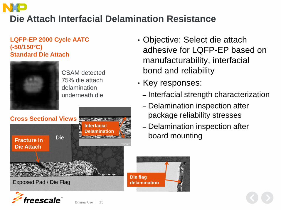
Die Attach Interfacial Delamination Resistance
• Objective: Select die attach
adhesive for LQFP-EP based on
manufacturability, interfacial
bond and reliability
• Key responses:
‒ Interfacial strength characterization
‒ Delamination inspection after
package reliability stresses
‒ Delamination inspection after
board mounting
LQFP-EP 2000 Cycle AATC
(-50/150°C)
Standard Die Attach
CSAM detected
75% die attach
delamination
underneath die
Fracture in
Die Attach
Die
Exposed Pad / Die Flag
Interfacial
Delamination
Cross Sectional Views
Die flag
delamination
TM
External Use 16
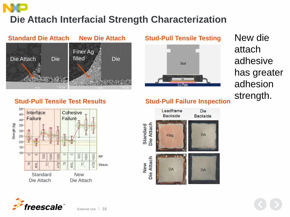
Die Attach Interfacial Strength Characterization
New die
attach
adhesive
has greater
adhesion
strength.
Stud-Pull Tensile Testing
Stud-Pull Failure Inspection
Sta
nd
ard
Die
Att
ac
h
New
Die
Att
ac
h
Die Die Die Attach
Standard Die Attach New Die Attach
Finer Ag
filled
Stud-Pull Tensile Test Results
Standard New
Die Attach Die Attach
Interface
Failure
Cohesive
Failure

TM
External Use 17
New Die Attach +
Thinner Die +
Further Design
Improvement
0% 3% 0%
New Die Attach +
Thinner Die 10% 50% 0%
New
Die Attach 15% 70% 0%
Non-
delaminated
region
Die Attach Delamination Performance in LQFP-EP
AATC (-50/150°C)
2000 Cycles 4000 Cycles
Certification Readpoints Extended Readpoints
1000 Cycles
New die attach, optimized die / package structure and package design
improvement produce consistent resistance to delamination in Temperature
Cycling, meeting AEC Grade 0.
Current
Die Attach 100% 13% 75%
Delaminated
region
Die Attach Delamination Criteria: > 30% die area

TM
External Use 18
Die Attach Delamination Performance at Board Level
Reliability Test (-40/125°C)
T0 Final Readpoint 5794 Cycles
Die to Flag (Die Attach) Interface Scan
Very robust reliability and high interfacial strength (no delamination)

TM
External Use 19
Wire Bonding
TM
External Use 20
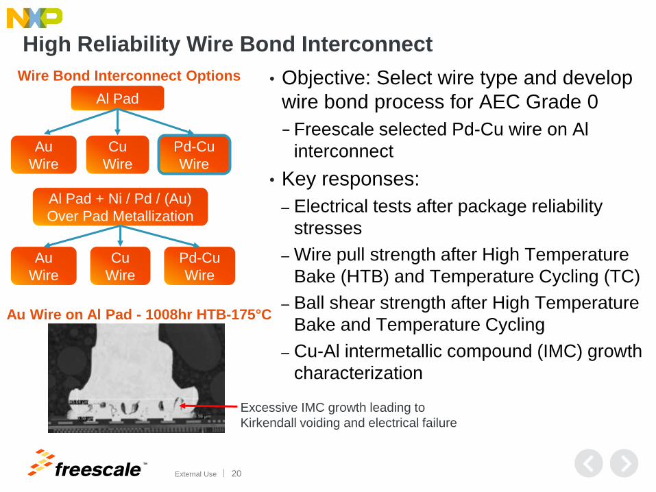
High Reliability Wire Bond Interconnect
• Objective: Select wire type and develop
wire bond process for AEC Grade 0
− Freescale selected Pd-Cu wire on Al
interconnect
• Key responses:
‒ Electrical tests after package reliability
stresses
‒ Wire pull strength after High Temperature
Bake (HTB) and Temperature Cycling (TC)
‒ Ball shear strength after High Temperature
Bake and Temperature Cycling
‒ Cu-Al intermetallic compound (IMC) growth
characterization
Al Pad
Au
Wire
Cu
Wire
Pd-Cu
Wire
Al Pad + Ni / Pd / (Au)
Over Pad Metallization
Au
Wire
Cu
Wire
Pd-Cu
Wire
Wire Bond Interconnect Options
Au Wire on Al Pad - 1008hr HTB-175°C
Excessive IMC growth leading to
Kirkendall voiding and electrical failure

TM
External Use 21
Optimizing Pd Coverage for Pd-Cu Ball Bonds
Pd Coverage on Free Air Balls (FAB) vs.
EFO Current for 3 Pd-Cu Wire Types
Pd Coverage on Etched Ball Bonds vs.
EFO Current for 3 Pd-Cu Wire Types
Pd-Cu wire B has best Pd coverage and widest EFO current window.
TM
External Use 22
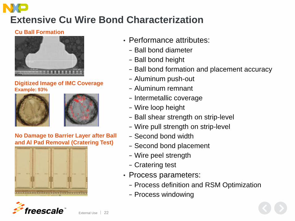
Extensive Cu Wire Bond Characterization
• Performance attributes:
− Ball bond diameter
− Ball bond height
− Ball bond formation and placement accuracy
− Aluminum push-out
− Aluminum remnant
− Intermetallic coverage
− Wire loop height
− Ball shear strength on strip-level
− Wire pull strength on strip-level
− Second bond width
− Second bond placement
− Wire peel strength
− Cratering test
• Process parameters:
− Process definition and RSM Optimization
− Process windowing
Digitized Image of IMC Coverage Example: 93%
No Damage to Barrier Layer after Ball
and Al Pad Removal (Cratering Test)
Cu Ball Formation

TM
External Use 23
Achieving No Wire-Pull Ball-Lift Failures after HTB
• Ball lift after decap / wire pull at 1000 hour HTB-175°C observed on bare Cu but NOT on Pd-Cu wire on Al pad.
• Hairline crack above Al-rich IMC found with bare Cu wire caused ball lift.
• Pd-Cu wire designed to regress IMC formation.
Cu Wire on Al at 1000 HTB-175°C
Pd-Cu Wire on Al at 1000 HTB-175°C
Cu Ball
Pd-Cu Ball
Intermetallic Formation Reaction Rate K (cm2/sec)
Temperature
(150°C)
Au - Al 110 X 10-16
Cu - Al 3.18 X 10⁻¹⁶
PdCu - Al 2.89 X 10⁻¹⁶
Ball Lift
Hairline crack
above IMC
Cu-Al IMC

TM
External Use 24
Achieving No Wire-Pull Ball-Lift Failures after Temp
Cycling
• Ball lift after decap / wire pull at 2000
AATC cycles observed on both bare
Cu and Pd-Cu wires on Al pad.
• Crack in Al pad caused ball lift
during wire pull.
• Assembly process optimized to
eliminate ball lift issue after
Temperature Cycling.
Cohesive Crack in Al
2000 Cycles of Temperature Cycling
Ball Lift
Al and underlying layer
Pd-Cu Ball

TM
External Use 25
Exceeding AEC Grade 0 Requirement
Passed electrical test at 2X AEC Grade 0.
Passed decap / wire pull and ball shear at 2X AEC Grade 0 with
no ball lifts.
Ball Shear (gf) Wire Pull (gf)
LSL = 1.8gf for 20um wire LSL = 9gf for 43um ball diameter

TM
External Use 26
Molding

TM
External Use 27
Epoxy Mold Compound for AEC Grade 0
• Objective: Select an epoxy mold
compound for LQFP-EP / LQFP
packages for manufacturability,
passivation die top interfacial bond
at AEC Grade 0 reliability.
• Key responses:
‒ Electrical tests after package
reliability stresses
‒ Delamination inspection after
package reliability stresses
LQFP-EP
2000 AATC Cycles
(-50/150°C)
Standard Epoxy Mold Compound
200µm
200um delamination between mold
compound and passivation die top surface
Die Top (C3)
Delamination

TM
External Use 28
Higher Stress at Die Corner 3
Silica filler loss opposite the mold gate entrance at passivation die
top corner (C3) has higher stress causing interfacial delamination
under cyclical loads.
Die Corner 3 (C3) Die Corner 1 (C1)
Filler loss

TM
External Use 29
Current
Mold Compound
Optimized
Die/Pkg Structure +
Process Changes +
Mold Compound
Die Top Interfacial Delamination Resistance Results
AATC (-50/150°C)
Certification Readpoints - 2000 cycles Extended Readpoints – 4000 cycles
Optimized die/package structure, mold process and new mold compound
produce consistent resistance to “passivation die top” delamination during
AEC Grade 0 temperature cycling across several LQFP/LQFP-EP products.
100%
> 200 µm
delamination
100%
>160 µm
delamination
0%
No
delamination several products
1%
~60µm
delamination

TM
External Use 30
Summary
TM
External Use 31
Session Summary
• Modern automotive environments impose new application profiles
at higher temperature and longer duration.
• The requirement for next-generation powertrain product packaging
is AEC Grade 0 which is 2X the current requirement.
• Freescale LQFP-EP package is a cost-effective solution meeting
and exceeding the challenging AEC Grade 0 packaging reliability
requirement.
TM
External Use 32
For Further Information
• SME Contact information
− Tu Anh Tran, C55 Packaging Technical Lead

TM
© 2014 Freescale Semiconductor, Inc. | External Use
www.Freescale.com