Master CYTEA – Domenico LAURIOLA
129
Master CYTEA – Domenico LAURIOLA
Transcript of Master CYTEA – Domenico LAURIOLA

Master CYTEA – Domenico LAURIOLA

Master CYTEA – Domenico LAURIOLA

Combining Efficiency and Aesthetics Through The Integration Of
Structural Topology Optimization in Architecture
Degree of Master of Science and Building Technologies in Architecture at
Technical University of Cartagena
Domenico Lauriola
Faculty of Architecture and Building Engineer. Technical University of Cartagena
Master CYTEA – Domenico LAURIOLA

Master CYTEA – Domenico LAURIOLA

Technical University of Cartagena
Department of Applied Mathematics and Statistics
Department of Structures and Construction
Director
Mathieu Kessler
Department of Applied Mathematics and Statistics
Co-Director
Jesús Martínez Frutos
Department of Structures and Construction
Master CYTEA – Domenico LAURIOLA

Master CYTEA – Domenico LAURIOLA

Abstract
The eternal fight of the functionality and aesthetic has written a large portion of the
construction history. Engineer versus architect. The modernity has accentuated the
problem because of the entrance of more variables: money and velocity. But is there any
way to go out from the fights and approach the contemporaneity?
Probably the best way to figure out this problem is to look to the duality of aesthetic and
functionality into the nature. How the nature has solved this problem according to the
thermodynamics’ and physic’ laws? is there any algorithm to simulate this process?
This works is going to try to find the better way to use the newest tools and the powerful
computing calculation capacity to solve the eternal fight. To pick out the better work flow
to generate a new architecture that has the capacity to merge the functionality aesthetic of
the nature into a new way to design a building.
Master CYTEA – Domenico LAURIOLA

Master CYTEA – Domenico LAURIOLA

Table of Contents
Introduction .................................................................................................................................................... 0
1-1 Objective ........................................................................................................................................ 1
1-2 State of the art of optimization techniques in architecture and its controversial opinion........... 1
1-3 BIM, software interoperability and optimization problems ......................................................... 6
Combining aesthetic and structural efficiency .............................................................................................. 8
2-1 Antonio Gaudí ................................................................................................................................ 8
2-1-1 The Method ............................................................................................................................... 8
2-1-2 Gaudí and his approach to the design problem ...................................................................... 12
2-1-3 Sagrada Familia ....................................................................................................................... 15
2-2 Pier Luigi Nervi ................................................................................................................................... 21
2-2-1 Palace of Labour ...................................................................................................................... 25
2-2-2 Burgo Paper Mill ...................................................................................................................... 28
2-2-3 Nervi’s method for evaluating isostatics ................................................................................. 31
2-3 Felix Candela ................................................................................................................................ 35
2-3-1 Optimal concrete shells ........................................................................................................... 39
Connecting architecture and engineering through structural Topology Optimization .............................. 42
3-1 Topology Optimization Formulation .......................................................................................... 42
3-1-1 Problem statement .................................................................................................................. 42
3-1-2 Structural Optimization ........................................................................................................... 44
3-1-3 Sizing Optimization ................................................................................................................. 44
3-1-4 Shape Optimization ................................................................................................................. 45
3-1-5 Topology Optimization ........................................................................................................... 45
3-1-6 Evolutionary Structural Optimization (ESO) .......................................................................... 53
3-1-7 Iso-Eso Optimization ............................................................................................................... 55
3-1-8 Tree-Inspired Optimization ..................................................................................................... 60
Applications of topology optimization in architectural design ................................................................... 67
4-1 A form finding tool for evolutionary topology optimization ...................................................... 67
4-2 Tool validation through academic examples .............................................................................. 70
Master CYTEA – Domenico LAURIOLA

4-2-1 Fixed board bridge with uniform vertical force .......................................................................70
4-2-2 Optimum design topology with ESO method for traction and compression structures ........73
4-3 Applications to architectural design ............................................................................................83
4-3-1 One column ribbed floor case ..................................................................................................83
4-3-2 Four columns ribbed floor case ................................................................................................90
4-3-3 Computer-aided form finding and optimal design of branching structures – parking roof example .................................................................................................................................................97
4-3-4 Topology Optimization – Bridge Example .............................................................................104
Conclusions .................................................................................................................................................109
5-1 SWOT Analysis ...........................................................................................................................110
Bibliography ................................................................................................................................................113
Master CYTEA – Domenico LAURIOLA
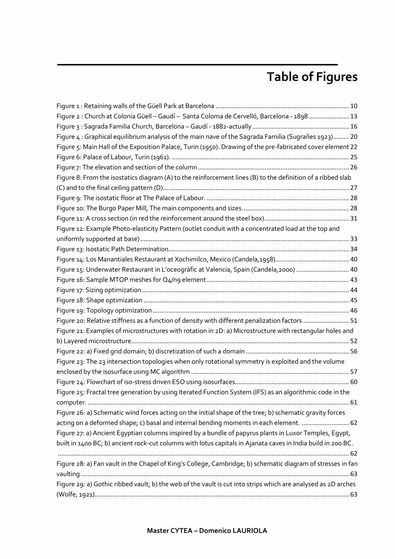
Table of Figures
Figure 1 : Retaining walls of the Güell Park at Barcelona ............................................................................ 10 Figure 2 : Church at Colonia Güell – Gaudí – Santa Coloma de Cervelló, Barcelona - 1898 ....................... 13 Figure 3 : Sagrada Familia Church, Barcelona – Gaudí - 1882-actually ....................................................... 16 Figure 4 : Graphical equilibrium analysis of the main nave of the Sagrada Familia (Sugrañes 1923) ......... 20 Figure 5: Main Hall of the Exposition Palace, Turin (1950). Drawing of the pre-fabricated cover element 22 Figure 6: Palace of Labour, Turin (1961). ..................................................................................................... 25 Figure 7: The elevation and section of the column ...................................................................................... 26 Figure 8: From the isostatics diagram (A) to the reinforcement lines (B) to the definition of a ribbed slab (C) and to the final ceiling pattern (D) .......................................................................................................... 27 Figure 9: The isostatic floor at The Palace of Labour. ................................................................................. 28 Figure 10: The Burgo Paper Mill, The main components and sizes. ............................................................ 28 Figure 11: A cross section (in red the reinforcement around the steel box). ............................................... 31 Figure 12: Example Photo-elasticity Pattern (outlet conduit with a concentrated load at the top and uniformly supported at base) ....................................................................................................................... 33 Figure 13: Isostatic Path Determination....................................................................................................... 34 Figure 14: Los Manantiales Restaurant at Xochimilco, Mexico (Candela,1958).......................................... 40 Figure 15: Underwater Restaurant in L’oceogràfic at Valencia, Spain (Candela,2000) .............................. 40 Figure 16: Sample MTOP meshes for Q4/n9 element ................................................................................. 43 Figure 17: Sizing optimization ...................................................................................................................... 44 Figure 18: Shape optimization ..................................................................................................................... 45 Figure 19: Topology optimization ................................................................................................................ 46 Figure 20: Relative stiffness as a function of density with different penalization factors .......................... 51 Figure 21: Examples of microstructures with rotation in 2D: a) Microstructure with rectangular holes and b) Layered microstructure ............................................................................................................................ 52 Figure 22: a) Fixed grid domain; b) discretization of such a domain ........................................................... 56 Figure 23: The 23 intersection topologies when only rotational symmetry is exploited and the volume enclosed by the isosurface using MC algorithm .......................................................................................... 57 Figure 24: Flowchart of iso-stress driven ESO using isosurfaces................................................................. 60 Figure 25: Fractal tree generation by using Iterated Function System (IFS) as an algorithmic code in the computer. ..................................................................................................................................................... 61 Figure 26: a) Schematic wind forces acting on the initial shape of the tree; b) schematic gravity forces acting on a deformed shape; c) basal and internal bending moments in each element. ........................... 62 Figure 27: a) Ancient Egyptian columns inspired by a bundle of papyrus plants in Luxor Temples, Egypt, built in 1400 BC; b) ancient rock-cut columns with lotus capitals in Ajanata caves in India build in 200 BC. ...................................................................................................................................................................... 62 Figure 28: a) Fan vault in the Chapel of King’s College, Cambridge; b) schematic diagram of stresses in fan vaulting. ........................................................................................................................................................ 63 Figure 29: a) Gothic ribbed vault; b) the web of the vault is cut into strips which are analysed as 2D arches (Wolfe, 1921)................................................................................................................................................. 63
Master CYTEA – Domenico LAURIOLA

Figure 30: a) Grand Palais in Paris built in 1900; b) Entrance gate of Paris Metro design by Hector Guimard in 1900. ..........................................................................................................................................................64 Figure 31: a) Umbrella structure of Skovshoved Petrol Station, Denmark, 1936; b) Mushroom umbrella structures, Baroni, 1938. ...............................................................................................................................64 Figure 32: a) Structural trees in Stuttgart Airport Terminal, Stuttgart, 1991; b) Schematic form diagram of Stuttgart Airport dendriforms. .....................................................................................................................64 Figure 33: a) Qatar National Convention Center (2011) ...............................................................................65 Figure 34: Topology optimization and size optimization for form finding of a 50 m long bridge and its shelter, inspired by the tree’s organic form (Frattari et al., 2013) ................................................................66 Figure 35: Some results of MATLAB implementation ..................................................................................68 Figure 36: ESO implementation – MATLAB-ANSYS ....................................................................................69 Figure 37: Design bridge ................................................................................................................................70 Figure 38: Optimum topologies with different stable state .........................................................................71 Figure 39: Performance Index Vs Number of stable state ............................................................................72 Figure 40: Poly-funicular miniature design by Gaudí – Sagrada Familia Museum – Barcelona ..................73 Figure 41: Design domain (a), ESO topologies obtained from a traction load case (catenary) ...................74 Figure 42: ESO topologies structure obtained from only-traction criterion with dead load case only. ......74 Figure 43: Performance Index and Volume Vs number of steady stable. ....................................................75 Figure 44: Initial design domain ....................................................................................................................76 Figure 45: Topology evolution. .....................................................................................................................77 Figure 46: Topology view SS= 25. .................................................................................................................77 Figure 47: Compression criterion ..................................................................................................................78 Figure 48: Arch formation near the base of the pillars. ................................................................................78 Figure 49: Compression criterion SS= 30 ......................................................................................................79 Figure 50: (a) Performance Index; (b) Volume ..............................................................................................79 Figure 51: Final Topology (Xie et al.) .............................................................................................................79 Figure 52: Topology evolution. .....................................................................................................................80 Figure 53: Criterion Compression SS= 59......................................................................................................81 Figure 54: Topology view ss= 59 ...................................................................................................................81 Figure 55: (a) Performance Index; (b) Volume ..............................................................................................81 Figure 56: Design domain .............................................................................................................................84 Figure 57: Top view – Von-Mises case ..........................................................................................................86 Figure 58: Gatti Wood Factory ribbed floor ..................................................................................................86 Figure 59: Top View - Only compression case ..............................................................................................88 Figure 60: Design Domain .............................................................................................................................90 Figure 61: Top view - Von-Mises case ...........................................................................................................92 Figure 62: Palace of Labour’ ribbed floor; a) photo b) isostatics lines .........................................................92 Figure 63: Parking roof design domain .........................................................................................................97 Figure 64: Bird-view of the optimum topology ............................................................................................99 Figure 65: Top view: Von-Mises case ............................................................................................................99 Figure 66: Bird-view of the optimum topology ..........................................................................................102 Figure 67: Top view - Only compression case .............................................................................................102 Figure 68: Bridge design domain ................................................................................................................104
Master CYTEA – Domenico LAURIOLA


Chapter 1
Introduction
The problem is the search of the best architectural form that’s the perfect convergence of
functionality and aesthetic. To reach this convergence you’re able to choose a designing
work flow. The chosen work flow It’s the “Topology Optimization”.
This method describes an entire family of computational algorithms to find the better
structural configuration of a specific structure or a specific part of structure. Where the
structural model it’s done with nodes and bars, this kind of optimization search the better
spatial configuration for the elements according to the mathematical variables used
(Structure’ weight, stress, internal stress reduction etc.).
This approach comes with the contemporary problems like sustainability and resilience. The
architectural space cannot be just a relative, beautiful space to show at architectural
magazines. The complexity of an architectural place cannot exclude the sustainability, the
efficiency, the structural efficiency because just the mix of the totality of this variable can
produce an Architectural space.
The topology optimization algorithm is being always used to optimize the parts of an
industrial process, but recently, this algorithm, is being used for civil engineer and
architecture problems. The most used for this kind of optimization are “Evolutionary
Structural Optimization”, “Bidirectional ESO” that were being used for the design of civil
constructions’ parts. (Beghini, Stromberg,Baker, Paulino, Mazurek,2011).
Master CYTEA – Domenico LAURIOLA
0

1-1 Objective
This work is going to focus on research of an equilibrium between aesthetic and structural
efficiency. Historically had been existed architects like Antonio Gaudí, Buckminster Fuller,
Pier Luigi Nervi o Felix Candela, with own aesthetic vision have produced innovating ideas
and form with an optimum structural performance. This work is going to set up a theoretical
and computational study about topology optimization techniques into structural design
workflow to get elegant solution that combine aesthetic and beauty with structural
efficiency too.
Evolutionary topology optimization techniques provide structurally sound and aesthetically
pleasing architectural designs, which commonly mimic nature's own evolutionary
optimization process. These techniques provide architects with a powerful tool to integrate
function and form in a synergistic way.
1-2 State of the art of optimization techniques in architecture and its controversial opinion
The most emblematic case of an optimization algorithm applied to the design of a building
or an architecture construction, is the “Voronoi algorithm”. It’s the one considered like the
golden section of the computational architecture. This kind of proportion it will be founded
into Le Corbusier essay “Le Modulor”. In fact, it’s the first architecture of modernity that
have detected the relationship between aesthetic and functionality with one of his phrases:
“The architecture engineering should approach without sacrificing emotion”.
Since from Greek culture have been existed words that can describes the generation of a
“Form”. The words “morphogenesis” is the union of “morphê” form and “geneisis” that means
creation, literally the creation of a form, the biological process that allow, to an organism,
the creation of a form.
Basically, many times, the computational architecture, like the Voronoi algorithm, do not
produce the best results and the better optimization according to the natural forms. This
can happen too for the effects of the scales and proportions used in the design phases. The
natural optimization the happen at a nanometre scales, it’s not the same of a building and
these differences can modify the entire process of optimization.
Master CYTEA – Domenico LAURIOLA
1

The next one generation of optimization algorithms has to consider the scale problem. Two
methodologies developed at “Massachusetts Institute of Technology”, the “variable
Property analysis” and “Variable property fabrication” are based on the “Functionally
Graded Materials” principle, that means the gradual variation of the composition and
structure into the volume.
The most important change of these two methodologies redefine the design process of the
architecture where, basically, a form generates a structure and from the structure choose a
material like a consequence of the first ones. In this case the process start from a material
according to the needs of the structure and then, the material will find the final form.
The fundamental issue that must be resolved in order to progress computational
architecture’s paradigm is one of intellectual integrity, finding its origins in the ability a
person has, or lacks, to be self-critical. The importance of stopping the problem at the
source through efforts made by educators must be emphasized in order to avoid the
looming magnification of the initial pseudo-science that has come to define much of
computational architectures output. For this reason, the Voronoi, with its associated
luggage, becomes the prime candidate for an introductory learning tool. Teaching a class on
computational architecture and setting a task that calls for 2D and 3D applications of the
Voronoi diagram should come first. As a study, it would highlight a student’s ability to think
creatively but also clearly establish those students who are able to think critically.
Manual De Landa, not alone in his painting of digital morphogenesis as architecture’s new
paradigm, is joined in the cause by another prominent theorist Neil Leach. Leach takes on
the more prominent role of promoter of the apparent shift in his publication Digital
Morphogenesis and book The Anaesthetics of Architecture.
Leach makes no apologies for his declarations, making clear in the opening lines: “This is a
polemical work. In an age when manifestos and polemics have become somewhat
unfashionable, such a work may appear out of place.” If the drawing of parallels between
Leach and Le Corbusier, the Voronoi and the golden section were not already clear, then
they should be now. The proselytizer approach taken by Leach is one that succeeded for Le
Corbusier; both The Anaesthetics of Architecture and Towards a New Architecture work to
build a rapport with fellow architects through the basic premise that the prevailing
paradigm is inadequate and ought to be replaced by mass adoption of the new. Where it
Master CYTEA – Domenico LAURIOLA
2

can be said that Le Corbusier succeeded, Leach’s attempt is debatable. This phenomenon of
attempting to define the details of the shift apparent is not limited to proclamations
expressed via manifesto:
“What characterizes most architectural conferences is that everybody is saying we’re in a
new environment, that there’s a paradigm shift of some sort, but everybody seems to
flounder at giving examples of and articulating what it is that’s new.”
For this reason, before even considering listing the qualities of the shift apparent, whether
self-imposed or otherwise, it is appropriate to look at what constitutes a shift, so that an
assessment of the current environment can be made against it.
The definition of a paradigm shift is such that a dramatic change in methodology or practice
within a field must take place, but additionally requires almost universal adoption amongst
practitioners of that field to be considered so. A paradigm shift is nothing short of a
revolution; one that is simply unapparent in the proclaimed shift from postmodernism to
digital morphogenesis. If, for argument’s sake, a paradigm shift was taking place, it would
be interesting to hear what De Landa and Leach make of buildings such as the Novotel and
algorithms such as the Voronoi being marketed to developers by architects under the guise
of digital morphogenesis, when in reality the theory behind the aforementioned solutions
amounts to nothing more than a pseudo-sustainability rant. Surely they too would see the
paradox here, being a contradicting mix of postmodernist references by way of
performance evoking imagery, ornament and veneer in order to mimic the potential of (an)
architecture, the potential of a valid optimal. Digital morphogenesis here is reduced to
nothing more than the blatant mysticism similarly professed in the infamous manifesto Le
Modulor over half a century earlier. It seems we have learnt nothing from architectural
history. Ultimately in the example of the Novotel’s veneered diagrid, lies the biggest irony
to Leach’s claim of a paradigm shift from postmodernism to digital morphogenesis. For it is
only in the preface of The Anaesthetics of Architecture where he describes postmodern
architecture as “design reduced to the superficial play of empty, seductive forms and
philosophy appropriated as an intellectual veneer to justify forms.”
The problem fundamentally lies in the intellectual integrity of architects. Evidently the ease
of applying pseudoscientific algorithms or simply a desire to mimic the „look‟ of the optimal
is behind the widespread lack of adoption of valid systems of topology optimisation that
Master CYTEA – Domenico LAURIOLA
3

should be coming to define the aesthetic of the actual paradigm shift only just beginning to
take place. There are a few possible reasons behind the lackadaisical approach. The first is
pragmatic in that many of the valid topology optimisation techniques mentioned are still
beyond the reach of most architects due to the “complexity of mathematics involved” and
the often obscure and cumbersome software used in generating a solution.The second and
more worrying, for it can’t be learnt, or rather unlearnt, is a problem that finds its origins in
the twisted philosophical position adopted by many of these architects. One way to answer
how such a stance could be considered acceptable is through an analysis of the thinking of
one of the main protagonist’s writing. De Landa’s work focuses on the theories of the
French philosopher Gilles Deleuze on the one hand, and modern science on the other. This
fact in itself should automatically raise interest as to where his true beliefs lie, for Deleuze’s
theories originate from the school of continental philosophers, who generally reject
scientism; thinking that does not bode well in its application to a movement that is
fundamentally based on computer science and biology.28 In this conflicting light, it is
possible to understand how De Landa and architects whose critical thinking originates from
the era of postmodernity, such as those who designed the Novotel, are stuck practicing a
brand of architecture that, although wanting to be optimal on the one hand, is just as happy
to pretend or signify an optimal on the other.
In order to avoid a magnification of the pseudoscientific traits exposed as technological
advances push the paradigm shift proper into reality, O’Sullivan has devised a scale of
theoretical positions.
According to O’Sullivan there are three position of an architect approaching the
computational architecture: Anti-Optimal, Formal-Optimal and Abnumeral-Optimal.
• Anti-Optimal: The severe end of the scale is the anti-optimal position. A work
deemed so presents with characteristics that are highly pseudoscientific.
Architectural production generated using inane methods such as those critiqued in
this thesis, including but not limited to the “Voronoi algorithm‟, the „Novotel
diagrid‟ or current „space syntax‟ applications, are examples worthy of designation
within this category. It is impossible for a computational architect employing valid
topology optimisation algorithms to be classified as anti-optimal. However, this
does not necessarily mean avoidance of formal-optimal classification.
Master CYTEA – Domenico LAURIOLA
4

• Formal-Optimal: A computational practitioner deemed formal-optimal is one who
strictly selects only the form generated by the computational algorithmic process,
without any intervention outside this process at any iteration. This position is
unfavourable because, by definition, it can only lead to technological determinism,
in that a deterministic system is one in which for everything that happens there are
conditions such that, given them, nothing else could happen. 52 This is also a
position of „tragic fallacy‟; in the sense that it is the very authorities on the topic, De
Landa and Leach, who, through their polemical writing advocating the removal of
the architect from the process and the “unleashing” of the computer program,
become the leading protagonists of such a position.
• Abnumeral-Optimal: The word abnumeral is first used in a series of lectures given
by Charles Sanders Peirce at Cambridge University in 1898. The meaning Peirce
ascribes to the word is in reference to a set of numbers that he says are distinct or
uncountable; they are “abnumeral.” 54 It is this interest in abnumeral, having the
connotations of being uncountable that has lent itself to describe experimentation
into the creation of methodologies that, on one hand rely heavily on the pure
mathematical domain of the computer, but seek to intervene through an
„uncountable‟ or abnumeral action on the other. Abnumeral-optimal being then the
theoretical position afforded to a computational architect who not only employs
valid topology algorithms in the computational generation of form but also employs
creative processes of intervention by way of non-standard analysis. This ensures
avoidance of either an inane or deterministic outcome, and celebrates the symbiotic
relationship of computer and architect. Therefore, the experiments contained here
are used to help define
The aesthetics of topology optimisation and non-standard analysis
From this Theoretical positions, this works is going to try to create a methodology to
approach the optimization of a form including the typical compositing work of architect.
To achieve this methodology, it will show some example of real case that have been
generating from composition of geometrical form until the effective built structure.
Master CYTEA – Domenico LAURIOLA
5

1-3 BIM, software interoperability and optimization problems
The exploration of parametric modelling and genetic algorithm optimization has increased
in recent years, with many research entities and companies alike developing tools and
methods to create a more robust and intelligent practice. Seeking to push the design and
development standards as they stand into new, more efficient methods adheres to the
intent of BIM modelling practices. BIMseeks to create multi-purpose models for
interdisciplinary work. In doing so, transfer of information becomes much more efficient,
creating multiple opportunities to save time and money. Many universities have studied the
benefits of BIM-oriented projects, and have seen substantial results in terms of both time
and monetary savings. Researchers at Auburn University dissected 10 United States
projects from 2005 to 2007 that implemented BIM technologies and strategies. They noted
that each project received a significant amount of net savings as well as rates of return on
the investments put forth for said projects (Salman et. all, 2008). The reasons, the authors
describe, for savings on a range of projects that included hotels, libraries, data centres, and
laboratories, are the integration of the architecture, engineering, and construction
disciplines. Such integration promotes “faster and more effective processes,” and “better
design.” The designs allow for building proposals that “can be rigorously analysed [where]
simulations can be performed quickly and performance benchmarked, enabling improved
and innovative solutions” (Salman et. all, 2008).
A key component to the success of BIM has been the impact of parametric, three-
dimensionalmodelling. Issues of deliverable speed, coordination amongst design parties,
and productivity, have become intrinsically woven into the interoperability of parametric
modelling (Autodesk, 2003). The simple schematic below illustrates the shift in paradigm,
from traditional linear design processes to compact and iterative solution networks.
Objectives of multiple parties have the ability to influence the final solution, or building
product, with the least compromise in cost and effort spent.
The philosophy of creating a system in which multiple sets of data from across the design
spectrum are accrued and manipulated in a parametric study is a crucial to the effectiveness
of BIM implementation.
Master CYTEA – Domenico LAURIOLA
6
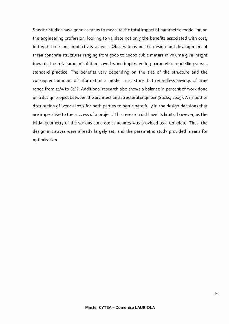
Specific studies have gone as far as to measure the total impact of parametric modelling on
the engineering profession, looking to validate not only the benefits associated with cost,
but with time and productivity as well. Observations on the design and development of
three concrete structures ranging from 5000 to 10000 cubic meters in volume give insight
towards the total amount of time saved when implementing parametric modelling versus
standard practice. The benefits vary depending on the size of the structure and the
consequent amount of information a model must store, but regardless savings of time
range from 21% to 61%. Additional research also shows a balance in percent of work done
on a design project between the architect and structural engineer (Sacks, 2005). A smoother
distribution of work allows for both parties to participate fully in the design decisions that
are imperative to the success of a project. This research did have its limits, however, as the
initial geometry of the various concrete structures was provided as a template. Thus, the
design initiatives were already largely set, and the parametric study provided means for
optimization.
Master CYTEA – Domenico LAURIOLA
7

Chapter 2
Combining aesthetic and structural efficiency
2-1 Antonio Gaudí
One of the most important figure of the architecture. He was the first that had connected
aesthetic with structural efficiency to generate a new kind of sacred architecture, with roots
on the past and with the vision to the real purpose of the aesthetic-efficiency mix.
2-1-1 The Method
Antoni Gaudí (1852 – 1926) was A Master builder. His work covers all aspect of architecture:
layout, ornamentation and stability. Any study of Gaudí’s work must embrace this global
concept of the project. For Gaudí, structural design was an integral part of architectural
design form its initial stages.
From his first projects, Gaudi showed his originality and independence. In particular, he
began to use systematically a type of arch not common in the western architectural
tradition. Instead of using arches with a shape derived from the circle (Roman, pointed,
basket-handle), he used arches with non-circular shapes: parabolic or “catenary”.
The use of this shape has a mechanical origin, which goes back to 1670 when Hooke raised
the following problem in a Royal Society Meeting: what is the ideal shape for an arch and
how much thrust does it impose on its buttress? Hooke gave the solution in an anagram
included in a book about helioscope: “As hangs the flexible line, so but inverted will stand
the rigid arch”
Master CYTEA – Domenico LAURIOLA
8

The problem had been studied until XIX Century and graphic mode to solve the problem
had been used. The Same method that Gaudi has received in his years as a student. Some
mention to the analogy with cables (and possibly the use of models) and, with certainty,
lectures about graphical analysis of arches and, perhaps, of vaults. However, Gaudi used the
concept of catenary arches in a completely original way: to integrate the structural design in
the process of architectural design. It is not a matter of verifying the stability of a certain
design; it is a matter of projecting, from the start, using stable shapes. As far as we know, it
is the first time that this attempt is made and exploited to its full capacity.
The most important problem is finding the shape of an arch that supports a certain load that
may be defined by two lines (or surfaces), the intrados and the extrados. In many cases, the
extrados is an initial datum and the loads are defined by the vertical distance between the
extrados and the intrados. The curve thatdefines the intrados must be of an equilibrated
shape (Rankinecalled this curve the "transformed catenary" and we shall use thisterm from
now on). In practice, this is the case for the design of abridge or of an arch over a doorway,
being part of a series of arches,or supporting a certain floor or vault. The exact
mathematicalsolution for this problem had already been studied: for the caseof bridges, by
Villarceau (1853) and in a completely general wayfor any load, by Rankine (1858).
The most common problem is to find the shape of a cable (orarch) that supports a load
proportional to the vertical distance betweenits directrix and a horizontal extrados. This
problem does nothave a direct solution and the mathematics are somehow complex.
Gaudi knew this, as is proven by the use of a symmetric catenaryarch to support an
asymmetric load. Gaudi found catenaryand parabolic curves aesthetically pleasant and he
used them evenwhen he could have used other kinds of shapes.
Parabolas, even simple catenaries, can be drawn directly. Transformed catenaries imply
complex mathematical calculations or using iterative graphic methods or hanging models.
Gaudi needed a design tool that allowed him to carry out quick calculations and alter the
design at will. The mathematical calculations, necessarily tedious in those days,
contradicted these requirements. Thus, Gaudi used the other two methods; the evidence is
both on his statements recorded in conversations with his disciples, Bergós (Codinachs
1982) and Martinell(1969), and on calculation sketches and photographs.
Master CYTEA – Domenico LAURIOLA
9

The process is not direct: first, a simple cable is hung and the loads that would act on it are
calculated, measuring the vertical distances (self-weight of the walls at the haunches) and
adding the corresponding weight of the floor. These weights are added to the cable,
causing a change on its shape. Vertical distances are measured again and the self-weight
modified. The cable under these loads adopts a shape that is very close to the exact
mathematical shape. This iterative process can also be carried out using graphical statics
and some of the corresponding sketches were published by Puig Boada (1976) and Tomlow
(1989).
Figure 1:Retaining walls of the Güell Park at Barcelona
The design and calculation of arches (or barrel vaults) is a problem that can be solved on a
two-dimensional plane. A vault is a spatial, three dimensional, problem. Following his
investigations on the design of arches, Gaudi studied the moregeneral problem of designing
vaults and, finally, complete buildings with equilibrated shapes.
Graphical statics allowed the analysis of vaults of fixed shapes. From the decade of 1870,
vaults are analysed by dividing, or "slicing," them into simple arches (see, for example,
Wittmann 1879). Thus, to analyse a cross vaulting we imagine each of the barrels "sliced" or
"cut" in a series of elementary arches. These arches are supported on the cross arches,
which transfer the loads to the springings. In this way, a feasible equilibrium solution is
Master CYTEA – Domenico LAURIOLA
10

obtained from the infinite range of possible solutions that can exist for an indeterminate
structure.
This idea of imagining three-dimensional vaults as being the sum of a series of arches
obtained by "slicing" the structure by a family of planes must have been applied for the first
time by Hooke in the last quarter of the XVII century, while working with Wren in the design
of St. Paul's dome. Just as it happened with the case of the catenary arch, he couldn't find
the correct mathematical expression, but some of the previous designs for
the dome shows the use of dome-like catenary shapes (the simplecatenary is substantially
different from the catenary surface for a dome). Hooke eventually stated that the ideal
profile for a dome is that of a cubic parabola, which is very close to the correct solution
(Heyman 1998).
Until the XIX century, Hooke, Bérard, Koerner and many other, had studied a mathematical
method to study the “membrane” theory or approach.
However, Gaudí did want to apply a non-traditional method: first, the vault is designed,
giving it a certain shape and dimensions (in the style considered to be most appropriate,
neo-gothic, neo-Byzantine, neo-Renaissance, etc.) and, then, its stability is checked using
graphic methods. Gaudi, as with arches, wanted to apply a design method that allowed him
to obtain equilibrated forms directly. Graphic statics, as mentioned already, can be used
comfortably in two dimensions (on the drawing surface). To fix the position of a line in space
three projections are needed, thus making space problems very laborious to solve.
Gaudi posed himself the problem of totally asymmetric vaults on irregular supports.
Without a continuous solution, he shifts from the vault problem to the problem of
projecting a building. His investigations took place in the context of the works for designing
and buildings the church at the Colonia Güell, which lasted eighteen years (10 years
designing plus 8 years building the crypt, while the church remained unfinished). On very
few occasions in the history of structures have so much time, effort and ingenuity been
devoted to investigating an idea.
Similarly, to the case of the transformed catenaries, the problem can't be solved directly
and it is required to carry out iterations. First of all, the main skeleton is created, where the
main cables represent the main thrust paths. This first model adopts a certain shape. Based
Master CYTEA – Domenico LAURIOLA
11

on this configuration, the area and weight of the elements are calculated and the model is
loaded using small sachets full of sand. These loads modify the shape of the model. The
weight is then recalculated and the loads are adjusted in the model to match the newly
calculated values. The model adopts a shape very approximate to the equilibrium shape.
The resulting shape can be observed, and could be altered by changing the geometry and/or
the loading. To show the volume ("give volume") of the model, Gaudi tried out different
methods. One of them consisted of taking a photograph and drawing on it with gouache,
right. On other occasions, he placed cloth or paper over the model before taking the
photograph, which would be drawn on as before. The hanging model functions like a
designing machine", as called by Collins (1971). When a satisfactory shape had been found,
Gaudi attempted to represent space using one of the methods described in the previous
paragraph. Lastly, he measured over the model to prepare the drawings. It is easily
imagined how laborious the whole process is.
The original model was destroyed. In the 1980's, Graefe and Tomlow attempted to
reproduce it. Tomlow wrote his doctorate thesis on the model and, lastly, published a book
(Tomlow 1989)describing with great detail the model investigation and reconstruction
works (nowadays the model is exhibited in the Sagrada Familia Museum, Barcelona).
2-1-2 Gaudí and his approach to the design problem
Every single analysis and design method used by Gaudi is basedon finding equilibrium
solutions. In a more technical jargon: Gaudi only uses the equilibrium equations of statics.
Sometimes he used models, some others he uses graphical statics, but he only used these
equations. The other two structural equations, which refer to material properties
(constitutive equations) or to the geometry of deformation (compatibility equations) are
fully absent.
Gaudi is applying the main idea of the "old vault theory", developed and applied in the
18'Gnd 191h centuries. This theory is based in finding equilibrium configurations where the
masonry
acts in compression. A safety factor was included in the design by "covering" the skeleton of
forces, the lines of thrust, with enough masonry to obtain a safety factor to account for
Master CYTEA – Domenico LAURIOLA
12

small movements or small variations in the loading (same as Gaudi did in his design for the
church at Colonia Güell).
At the end of the XIX Century, this approach was considered merely approximate, if not
incorrect. In effect, the thickening of the skeleton allowed the existence of not one
"skeleton of forces", butof an infinite number of them. Internal forces can't be
determinedusing the equilibrium equations alone and there are an infinitenumber of
suitable force paths or "skeletons" inside the masonry,every one of them in equilibrium with
the loads. Indeed, in thecase of the church at Colonia Güell, the current equilibrium stateis
very different from that calculated with the model as the churchwas never completed and
what remains is the crypt. The inclinedcolumns do not receive the load of the church
structure; however,it is a possible an equilibrium solution due to the
aforementioned"thickening" of the masonry around the funicular of forces.
Figure 2:Church at Colonia Güell – Gaudí – Santa Coloma de Cervelló, Barcelona - 1898
Engineers at the end of the XIX Century, deeply influenced by Navier's "elastic philosophy"
(defined by Heyman, 1999a, as Navier's, found this indetermination to be a big mistake.
They wanted to find the actual state of the structure, the actual way the loads were carried
Master CYTEA – Domenico LAURIOLA
13

to the ground. The solution was, then, to apply elastic analysis, i.e. to add the material
(linear- elastic) and compatibility (continuity of elements, boundary conditions) equations
to the equilibrium equations, previously used on their own.
Such arch would be considered to be perfectly built in, rotation and translation impeded.
This way a unique solution was obtained, a unique "elastic" line of thrust representing the
"actual state of the arch. However, cracks often appeared in masonry arches after striking
the centring, proving that the calculated "actual" state of the arch wasn't possible. There
was no answer for this problem. The evident contradiction, the fact that the calculated state
did not at all represent the actual physical structure, was almost systematically ignored,
with only some exceptions such as Swain 1927. Not with standing this, it was a fact that
those bridges Designed using elastic calculations were standing, just like those calculated
using the old theory. The contradiction was only resolved with the development of the
Plastic Theory (or Limit Analysis, or Fracture Theory). The same disparity between
calculations and actual deflections in structures was observed in the systematic tests on
frames carried out by the Committee for the Development of Steel Structures in UK in the
1920s. Plastic Theory was thus borne because Elastic Theory couldn't account for what was
being observed. The development of Plastic Theory reached its final point with the proof of
the Fundamental Theorems (in Russia, in 1936, by Gvozdev; rediscovered in the 1950's; cf.
Heyman 2001).
The Safety Theorem resolved the dilemma of the impossible task of finding the "actual"
state of the structure: if it is possible to find a distribution of internal stresses in equilibrium
with the external loads that doesn't violate the yield condition of the material, the structure
will be safe, it won't collapse. The equilibrium situation does not have to be the "actual" one;
it just has to be possible. The structure is, at least, as intelligent as the designer and before
collapsing it will find the projected equilibrium situation (there could be many others and
this Theorem justifies the stability of the crypt in the church at Colonia Güell).
In fact, the Safety Theorem leads to what Heyman has called the "equilibrium approach: to
design or analyse buildings made of a "plastic" material we can work exclusively with
equilibrium equations, checking afterwards that they don't violate the limit condition of the
material (in a frame, for instance, checking thatthe ultimate moment capacity is not
exceeded in any section). The elastic solution is a "possible" solution and is, also, safe, but it
Master CYTEA – Domenico LAURIOLA
14

is not more exact or real as any other equilibrium solution. The Plastic Theory was
developed for materials like steel that have a large enough plastic range to resist rotations
localised in specific places (plastic hinges). It was soon noticed that it could be applied to
reinforced concrete also (for elements with limited reinforcement). Professor Heyman has
pointed out that, in fact, he Safe Theorem can be applied to any structure built with a
material that shows a certain "plasticity", allowing the formation of hinges, even if they are
partial, and, of course, in the absence of local or global instability. We are talking about non-
brittle, hard materials.
For masonry, the yield condition of the material is that it must work in compression and, to
achieve that, the thrust must always be contained inside the structure. The Safe Theorem
can now be phrased as follows: if it is possible to draw a group of lines of thrust in
equilibrium with the loads inside the masonry, the structure is safe, the stability condition is
purely geometrical and the safety of masonry architecture depends on its geometrical form.
To the aforementioned we can add timber and masonry (Heyman 1995; Huerta 2001), even
if this seems surprising.
The approach used by Gaudi in designing his buildings is an equilibrium approach and it is
fully justified by the Safe Theorem. In fact, Gaudi was the first one to draw all the
consequences of the equilibrium approach: he didn't limit himself to verifying structures
previously designed, as had been the practice until then, but he deliberately designed
equilibrated structures. Of course, there are infinite solutions and Gaudi considered the
mechanical aspect as one of the many conditions that an architectural project must meet
and criticised strongly the formal determinism of what he called “Funicularism”.
2-1-3 Sagrada Familia
The final work by Gaudi, on which he worked until he died, is the Sagrada Familia Temple in
Barcelona. The project for the church of the Colonia Güell had allowed Gaudí to study in
depth the design and mechanics of arches and vaults of any shape. Surprisingly, at the
Sagrada Familia he abandons the funicular models approach that he had exploited in the
Colonia Güell project. The objective is different. The colonial Güell project doesn’t have
Master CYTEA – Domenico LAURIOLA
15

references to historic architectural styles. Every aspect of it has an experimental and
research character.
Figure 3: Sagrada Familia Church, Barcelona – Gaudí - 1882-actually
The Sagrada Familia has its origin in a previous neo-gothic project. Perhaps for this reason,
in his project Gaudí proposes a perfection of the Gothic style. He seeks vertical loads, he
seeks returning to the primitive basilica-like model (Sugrañes, 1923). In particular, he wants
to get rid of what he called "the crutches" of the Gothic: flying buttresses and external
buttresses. To make clear this point Sugrañes included in his article a comparison of the
equilibrium between the cathedral of Cologne and the Sagrada Familia. Of course, it is not
possible to transfer transverse loads in masonry structures without horizontal thrust, which
in turn has to be resisted by some buttressing system and, though afterwards he ignores
them, the necessary horizontal thrust is represented.
This objective of minimising the thrusts is present from the beginning of the long design
process. In the first project from 1878 he tries to reduce the thrust, increasing the height of
Master CYTEA – Domenico LAURIOLA
16

the cross and transverse ribs, looking for an almost pyramidal shape. The horizontal thrust
is reduced, but is still present. To hold it without the need for buttresses, Gaudi inclines the
columns, looking for the loads direction. This idea appears to be leading the project and
Gaudi had rested and researched it in depth in the construction of the portico at the crypt in
the church of Colonia Güell.
Gaudi abandons the funicular models and returns to graphical statics. However, it isn't the
statics of funicular polygons. This is a different concept. The point is to calculate and
equilibrate the loads like in a balance. Sugrañes' article describes the final stage of the
design of the grid of leaning columns supporting the central aisle, wall and part of the side
aisles, for a typical span. The shapes of the roof, vaults, walls and windows have been
defined prior to the calculation stage described in the article. Sugrañes does not comment
on the process followed to define the shapes of the roof and vaults. However, the geometric
complexity and building difficulty of the vaults, walls, pediments, etc., prove the existence
of a long design process, previous to the final equilibrium analysis described by Sugrañes.
The aim is to design the shape of the supporting skeleton ("tree") of columns.
The method for designing the columns is simple but very original. The main idea is to attain
equilibrium between the various blocks that compose the structure, as it would be done in a
set of scales. The structure is analysed in three main sections (central aisle, wall and side
aisle). 'Their total weight and centre of gravity position are calculated. Each section is
composed of a range of elements. The process is as follows: firstly, the weight and centre of
gravity of each element is calculated (using the standard graphic statics methods, says
Sugrañes) and, once these values are known, the weight and centre of gravity of each
section is calculated.
The main problem is how to take these loads to the bases of the columns, which are already
fixed in position (the crypt of the old neo-gothic design was already built); i.e. a skeleton of
columns, a "tree" of columns, must be designed to be capable of collecting the loads from
the centre of gravity of each section and transferring them to some fixed points on the
ground. It is assumed in this equilibrium calculation that each section transmits its load
vertically to the corresponding branch of the tree.
Thus, the concept of equilibrium is very different from the purely funicular system applied in
the design of the church for Colonia Güell. This concept of equilibrium is what we could call
Master CYTEA – Domenico LAURIOLA
17

global or for a "block system structure, where each part, made up in turn of a series of
elements, forms a block. These blocks, according to Sugrañes, don't interact with each
other, but the branches of the skeleton seek to collect their concentrated weights at their
centre of gravity. There is no arching action, no lateral thrust, and this is so, according to
what Sugrañes says, because they would be made of a "concrete-like" material through the
use of metal reinforcement. Since the majority of the elements, the vaults in particular, are
defined by ruled surfaces, there would be no problem in placing straight reinforcing bars. In
the case ofthe vaults, some of these bars could be used as centring during construction.
Thus, the vaults could be constructed without traditional centring.
The weights and centres of gravity of the main parts are fixed. The base of the column was
also fixed. Gaudi used a graphical method to design the tree that is going to collect the
weights and take them to the bases of the columns. As it has been already mentioned,
graphical statics methods become very complex for solving 3D equilibrium problems, since
three projection planes are needed to define a segment in space. The webs of the nave and
aisles of the Sagrada Familia have two symmetry planes, simplifying the problem. Graphical
statics are easier to apply in this case. Gaudi studied one-half of the aisle, which also has a
vertical symmetry plane, perpendicular to the axis of the aisle. Given these two properties,
it is easy to check various equilibrium solutions projecting on two planes. The final
equilibrium solution is represented in Figure 4.
Of course, horizontal thrust is needed when compensating leaning forces: loads can't be
translated horizontally (in the absence of bending- elements such as beams) without an
arch action. Given the verticality of the project, these thrusts are small, but unavoidable.
Sugrañes assumes that horizontal thrusts are developed in the symmetry plane of the
central and lateral aisles. These thrusts determine the inclination of the columns. (Some
columns are subdivided inside the plane defined in the general scheme, but equilibrium is
guaranteed by the symmetry that always equilibrates the horizontal thrusts.) Then, the
column weights are calculated, and, finally, after a few trials, the equilibrium skeleton can
be drawn.
The most polemical aspect of this process could perhaps be the assumption that vaults and
roofs don't generate any thrust. The thin vaults (not so thin in this case: Sugrañes calculates
the weight based on a thickness of 450 mm), whether or not they are reinforced, require
Master CYTEA – Domenico LAURIOLA
18

certain edge conditions to obtain an equilibrium state, acting as a membrane (disregarding
bending). This is the expected behaviour for a well-designed shell or vault. The edge forces,
which are thrusts mainly, can be equilibrated by the reinforcement in the floors. The weight
of the vaults over the aisles is small and, thus so is the thrust they originate. Nevertheless,
those thrusts exist and they must be compensated.
Master CYTEA – Domenico LAURIOLA
19

Figure 4 : Graphical equilibrium analysis of the main nave of the Sagrada Familia (Sugrañes 1923)
Master CYTEA – Domenico LAURIOLA
20

2-2Pier Luigi Nervi
Pier Luigi Nervi (1891-1979), a structural engineer, also called the «Constructor» or the
«Architect», started his practice in the late years Twenties and continued till the early
Seventies. This long, fruitful period includes the development of his structures and the
studies and tests about the structural pre-casting.
The Nervi's approach to the building process is global. This extraordinary achievement is
reached by mastering all the factors which condition the building process, namely the
experimentation of new structural configurations and of building process, the planning and
the realization of specific constructions, the production of structural elements, the same
building process meant as studies for a logical economical progression of the building
activity and the planning of the provisional works, the aesthetic aspects, the economics of
the construction.
Nervi does not plan his construction in the traditional way: on the contrary, the whole
building is conceived from the foundation, also in ¡he vertical supports, even in anyone of
the structural elements, as a rational composition of parts principal and secondary of the
covering vault or floor. In the case of vaults, the research is carried out following the method
of prefabrication of thin, light, strong elements, flat or grooved, which are placed in the final
position and later connected by ribs of reinforced concrete castin the empty spaces left on
purpose between the sameelements, this way producing a network of members which are
oriented in two main directions and kept intheir position by the prefabricated elements, a
kind ofwarp of knitted tissue. Nervi shows to follow the great, noble constructional tradition
in the research and realization of large-span, thin, light vaults as it has been manifested by
the western architecture since the ancient roman time and continued in Europe and in the
Near East, namely in Iran; to a very large extent, in fact, the research on vault planning is the
most peculiar feature of the architecture of these constructional civilizations.
The researches on structural types are supported by those on building material s and
especially on the reinforced concrete and on the “ferro-cemento” etc.
Amongst the many Nervi's inventions and realizations, one of the most interesting is the so
called «strutture cementizie ondulate», Figure 5, (patent of industrial invention 1948), i.e.
Master CYTEA – Domenico LAURIOLA
21

the corrugated vaults. The invention consists in the use of thin prefabricated elements long
from 2 to 3 m of “ferrocemento”, with the cross section shaped as a semi-wave. steel bars
come out of the body of the elements in order to realize an efficient transversal connection
between the single pieces. To avoid instability of the long, thin elements during the transfer
and when in situ, triangular, therefore indeformable, meshes of braces prefabricated in the
same way, are added to the elements; in some versions, these are completed with smart
undulated transversal diaphragms which have the same function of the bracing. The
triangular bracings and the diaphragms are used as stiffening during the transfer in the site
of the yard, when are in situ become part of horizontal rings -like parallels of the globe -
which are connected with the radial elements - half-meridians- of the waves.
Figure 5: Main Hall of the Exposition Palace, Turin (1950). Drawing of the pre-fabricated cover element
The “ferrocemento” in the version for which Nervi got a patent in 1943, is constituted by
several layers of iron net (thickness inferior to the millimetre and meshes of about one
centimetre), connected by thin iron wires; this skeleton is later covered by concrete of
plastic consistence, with modest mechanical properties, made with high quality, high
percentage cement melt with water and sand. The composite “ferro-cemento” has very
peculiar properties such as: perfect structural isotropy, due to the homogenous distribution
of the reinforcement; an excellent behaviour both to tension and compression; high
Master CYTEA – Domenico LAURIOLA
22

extendibility and, at the same time, high superficial tension, properties which prevent it
from cracking, «inrompibile» as Nervi defined it with an Italian neologism. The boxing,
made of wood or metal or chalk, to be used an indefinite number of times, is laying on the
soil during the positioning of the reinforcement and the cast of the concrete; bottom and
side surfaces can be smooth or dressed according to the refinement quality and level
requested for the final product. The prefabrication allows to realize elements with a curved
surface and the presence of material only where really needed for the structural function,
something which is rather difficult and anyhow very expensive with the traditional
reinforced concrete. The possibility of connecting all the elements prefabricated in the said
way by means of a network allows the monolithic response of the work.
In the case of the grooved vaults, a steel reinforcement of longitudinal bars (high resistance
steel if a pre-tension is planned) is placed, from the extrados, at the bottom of the wave and
at the crest; concrete is poured on both reinforcements to form Radial ribs from the top of
the vault to the springings. The resistant masses of steel bars, being placed at the maximum
distance from the neutral axe, as Nervi says in the patent request, exploit the maximum
efficacy. It is clear therefore that the waves have the function to keep the steel
reinforcement, in a way they act as distances even if they co-operate to the bearing
function; in fact, they can have voids for windows at one or at both sides, as Nervi says,
besides they realize the closing of the building and do not need further protection against
weather because they are water-proof and «infessurabile» another Nervi’ neologism like
«inrompibile».
To discover the essence of the Nervi's aesthetical theories and at the same time to find a
key to the interpretation of his works we need to recall some of his most important
statements.
“L'indipendenza di spirito . . . e una condizione assolutamente Indispensabile per quanto riguarda il lato estetico.”
“The independence of spirit. . . is a condition absolutely indispensable as regards the aesthetic side”
“il carattere di una costruzione non dipende dalla sagoma delle modanature, dalla dimensione delle finestre, o da
qualche particolare carattere decorativo, ma fondamentalmente dai rapporti di volumi, di forme, dalle
Caratteristiche delle strutture portanti, da quel complesso, Insomma, di elementi che riguardano non la rifinitura
ma lo Scheletro e l'organismo strutturale dell’edificio.”
Master CYTEA – Domenico LAURIOLA
23
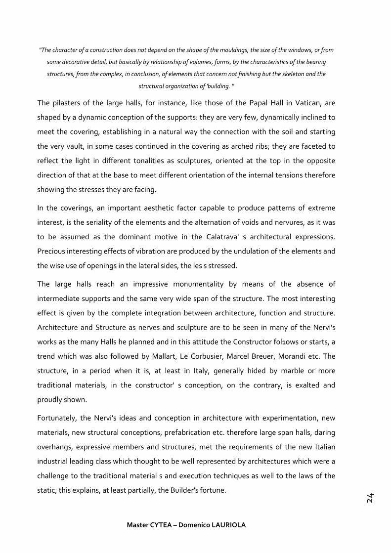
"The character of a construction does not depend on the shape of the mouldings, the size of the windows, or from
some decorative detail, but basically by relationship of volumes, forms, by the characteristics of the bearing
structures, from the complex, in conclusion, of elements that concern not finishing but the skeleton and the
structural organization of 'building. "
The pilasters of the large halls, for instance, like those of the Papal Hall in Vatican, are
shaped by a dynamic conception of the supports: they are very few, dynamically inclined to
meet the covering, establishing in a natural way the connection with the soil and starting
the very vault, in some cases continued in the covering as arched ribs; they are faceted to
reflect the light in different tonalities as sculptures, oriented at the top in the opposite
direction of that at the base to meet different orientation of the internal tensions therefore
showing the stresses they are facing.
In the coverings, an important aesthetic factor capable to produce patterns of extreme
interest, is the seriality of the elements and the alternation of voids and nervures, as it was
to be assumed as the dominant motive in the Calatrava' s architectural expressions.
Precious interesting effects of vibration are produced by the undulation of the elements and
the wise use of openings in the lateral sides, the les s stressed.
The large halls reach an impressive monumentality by means of the absence of
intermediate supports and the same very wide span of the structure. The most interesting
effect is given by the complete integration between architecture, function and structure.
Architecture and Structure as nerves and sculpture are to be seen in many of the Nervi's
works as the many Halls he planned and in this attitude the Constructor fol1ows or starts, a
trend which was also followed by Mallart, Le Corbusier, Marcel Breuer, Morandi etc. The
structure, in a period when it is, at least in Italy, generally hided by marble or more
traditional materials, in the constructor' s conception, on the contrary, is exalted and
proudly shown.
Fortunately, the Nervi's ideas and conception in architecture with experimentation, new
materials, new structural conceptions, prefabrication etc. therefore large span halls, daring
overhangs, expressive members and structures, met the requirements of the new Italian
industrial leading class which thought to be well represented by architectures which were a
challenge to the traditional material s and execution techniques as well to the laws of the
static; this explains, at least partially, the Builder's fortune.
Master CYTEA – Domenico LAURIOLA
24

2-2-1 Palace of Labour
Figure 6: Palace of Labour, Turin (1961).
The problem: An area of 25.000 m2 to cover in one year and the better compromise
between the political value of a building commemorating the Centenary of the Republic and
its function afterwards and, perhaps above all, the feasibility of constructing it in such a
short time.
The solution: Change a big dome roof solution with a series of smaller, independent roof to
cover the wall area.
The large covering was planned to consist of sixteen square plates (38×38 m) supported by a
25 m high central column. The connection between the plate and the pilaster was provided
by a steel capital to which the 20 beams (composed by welded components) are bolted.
Four perimeter beams would then stabilise the cantilevered elements. Between each plate a
2.5 m wide glass strip panel was inserted to provide natural light.
Master CYTEA – Domenico LAURIOLA
25

The whole construction process of the huge structure could be reduced into the systematic
construction and subsequent juxtaposition of sixteen identical structural elements: one
pillar surmounted by one square plate: the ‘mushrooms’, nick-named by Nervi’s office.
The construction of the columns in exposed reinforced concrete presented various issues.
The main one was that it was crucial to have perfect vertical alignment of the columns,
especially at the top where the steel capital was to be placed. This is very difficult to achieve
with normal timber forms. Even more importantly, it was difficult to provide a continuous
surface between the cruciform base and the circular top of the columns. As there would be
no time for corrections the columns had to be constructed perfectly from the very
beginning. Finally, the forms for the columns had to be accurately placed by a crane and it
had to have its own stability. The final solution was to build a single steel framework,
composed of six components bolted together which could be dismantled, with which to
erect all sixteen columns; a huge ‘machine’. The concrete was to be poured in three
different stages, each one every two components.
Figure 7: The elevation and section of the column
Master CYTEA – Domenico LAURIOLA
26

A system of movable forms in ferro-cemento was employed to quickly build the structure of
the floors, ‘signed’ by Nervi by his isostatic intrados. The isostatic lines are, in this case, the
strain-lines of the bending moment present in the rectangular slab supported at its corner
by four columns. Nervi placed the reinforcement bars along theselines achieving at the
same time an elegant and, to some extent, structurally correctsolution. Indeed, this solution
would be more correct without the presence of the ribs asthe isostatics are coplanar to the
slab and, moreover, the presence of the ribs changesthe overall geometry of the building
element (the slab) and hence the way that strainsflow within it.
Figure 8: From the isostatics diagram (A) to the reinforcement lines (B) to the definition of a ribbed slab (C)
and to the final ceiling pattern (D)
Master CYTEA – Domenico LAURIOLA
27

Figure 9: The isostatic floor at The Palace of Labour.
The Palace of Labour in Turin demonstrated Nervi’s ability to master the construction of a
large building within strict conditions. However, it also demonstrated his limitations as a
pure designer of space. Indeed, it can be argued that to limit the whole design of a
monument to the nation by the mere planning of its construction methods and the
technologies involved, although ingenious, may diminish the significance of the
architecture in its tri-dimensional and symbolic aspects. Furthermore, the decision not to
build a second floor has complicated the chances to use this building after the celebration of
the centenary. On this occasion, Nervi seemed to be more concerned about the definition
and realisation of the components rather than the overall final product. However,
considering the close deadline and the overall aesthetic finishes that Nervi provided to the
gigantic structure, this was clearly an acceptable compromise for the judging panel.
2-2-2 Burgo Paper Mill
Figure 10: The Burgo Paper Mill, The main components and sizes.
Master CYTEA – Domenico LAURIOLA
28

• 1: The base - on two levels - which supports the continuous paper machine.
• 2: The steel-glass curtain walls which enclose the whole building.
• 3: The flat steel roof and its supportive, composite structure.
The problem: The burgo process needs an overall production length of 100m. The whole
area had to be free from any vertical structural elements for at least 150 m, which meant
that, after consideration of all ancillary spaces and working areas, the whole structure had
to be approximately 250 m long and 30 m wide without internal columns: a gigantic, empty
box.
The solution: Nervi explored the option of a structure composed of two 200 m long lowered
arches in reinforced concrete but had chosen a horizontal roof that has similarities between
the Burgo and Nervi’s proposal for the bridge over the Sicilian Channel (Cresciani,2007).
Nervi’s practice proposed two variations in terms of materials but, again, economic
considerations and concerns regarding the speed of construction ensured that the steel-
concrete option prevailed over the purely reinforced concrete solution.
The variable section of the pylons and their overall shape, as is usual in Nervi’s structural
elements, are suggested by the line of stresses transmitted by the suspended ceiling to the
ground.
The main problem for this particular case, and also a central point in Nervi’s design process,
was how to avoid the huge amount of carpentry required to assemble the wooden or metal
cast forms for such a difficult shape and also their inevitable waste. These were typical
building site issues for which Nervi proved to be an indefatigable innovator, here he applied
a spectacularly simple but effective procedure. Initially, panels in reinforced concrete (7 cm
thick) were carefully prefabricated in-situ at ground level. These were reinforced concrete
self-supporting box moulds which were then filled according to the sequence of the large
poured sections, to which they remained as an external ‘skin’: this solution was effective and
avoided the wastage of materials.
Once the four supports were erected, the involvement of the Antonio Badoni Company was
requested in order to build and install the suspended roofing in Spring 1962. The links
Master CYTEA – Domenico LAURIOLA
29

between the steel roof and the external supports are four suspended chains which form, in
the central part, a parabolic curve. This curve is actually fragmented in a series of
independent rigid steel bars jointed (bolted) every 10 m. The connection between the chain
and the reinforced concrete pylons is provided by four steel boxes placed within the cross
beam at the summit of the four supports (see Figure 11. At intervals of 10 m, corresponding
with the joints, 92 vertical rods of 45 mm diameter support the four lattice steel beams
which act as the principal structure of the roof; cross-beams ensure the overall stability of
the roof, which has an overall thickness of 2.1 m. The Burgo Paper Mill represents the apex
in Nervi’s hybrid-works. The massive use of steel became here of the greatest structural
relevance. Nervi was aware of this fact and arguably this is the reason why he called Gino
Covre again after their recent collaboration at the Palace of Labour in Turin. Despite the
design team was the same (Nervi-Covre), the project of the Burgo Factory differs
considerably from the Palace of Labour: the former is a building clearly conceived from the
‘outside’ whereas the latter was developed from the ‘inside’. This makes the Burgo a less
recognisable work of Nervi’s, who was a theorist of the ‘from the inside to the outside’
design process. The only part in which Nervi’s hand is apparent in this work is probably the
storage area below the paper machine, where he returned to the one of his favourite
themes: the ribbed ceiling.
Master CYTEA – Domenico LAURIOLA
30

Figure 11: A cross section (in red the reinforcement around the steel box).
2-2-3 Nervi’s method for evaluating isostatics
Nervi had studied and investigated many analysis methods but the most important are the
studies about his isostatic design based floor.
• Strain Gauge Methods
Strain gauge methods rely on devices capable of measuring strain via mechanical,
optical, electrical, acoustical, and pneumatic methods, to determine the
displacements and stresses at points on a small-scale model.
To find the stress field on the surface of a flat slab, it is necessary to use three-
element strain gauge rosettes. These rosettes include three strain-gauges, each
oriented at a different angle relative to the two in-plane axes (x and y), which provide
three strain measurements corresponding to the three orientation angles. Using
Master CYTEA – Domenico LAURIOLA
31

strain-transformation equations, the three Cartesian components of strain (εxx, εyy,
and γxy) can be calculated and can be used to find the principal strain direction at the
measurement location. While calculating the principal stress directions from the
rosette readings is simple, the experimental preparations and procedure are costly
and time-consuming. Several rosettes would be needed to obtain enough data to
clearly represent the full field of principal stress trajectories. Because this method
does not provide a more accessible way to obtain isostatics than theoretical
calculations, strain gauge methods could not have been Nervi’s initial means of
finding isostatics.
• Photoelasticity
Photoelasticity is derived from the strain- and stress-optics laws (Neumann 1841,
Maxwell 1852) on the theory of artificial double refraction (anisotropic birefringence)
in a stressed isotropic, transparent solid. In 1816, Brewster coined the term
photoelasticity due to the colour pattern produced in clear glass when stressed and
examined under polarized light. When certain transparent materials undergo stress,
the material exhibits birefringence. As polarized light passes through the material,
the rays refract and separate into two perpendicular components each parallel to the
principal refractive indices of the material. A condition of the stress-optics laws
states that these principal indices correspond to the principal stress directions. In 2D
cases, small-scale models with plane stress conditions are placed in a polariscope,
which allows analysis of a model under polarized light. There are two types of optical
interference patterns, isoclinic and isochromatic. Isoclinic designate the locus of all
points where the principal stress directions are parallel to the directions of the
polarizing axes, appearing as black bands. Isochromatic define the locus of all points
having equal difference between the two principal stresses (constant maximum
shear stress) appearing either as a field of dark fringes or a continuous range of the
visible spectrum, depending on the light source.
Master CYTEA – Domenico LAURIOLA
32

Figure 12: Example Photo-elasticity Pattern (outlet conduit with a concentrated load at the top and uniformly
supported at base)
• Mathematical Theory
As no efficient experimental approach existed at the time, Arcangeli theoretically
studied the concept of placing ribs along the isostatics of principal moments in
proposing the idea to Nervi. The two most commonly used plate theories are the
Kirchoff-Love and Reisner-Mindlin plate theories. The Kirchoff-Love theory,
applicable to thin plates, was developed by Love in 1888 using Kirchhoff’s 1850
boundary condition assumptions. Reissner-Mindlin plate theory, an extension of
Kirchoff-Love plate theory and applicable to thick plates, takes into account shear
deformations through the thickness of a plate and was proposed by Reissner in 1945,
but not fully developed by Mindlin until 1951. Given this timeline, Arcangeli’s
theoretical calculations for the principal bending moment directions must have been
based on Kirchoff-Love thin plate theory. Although thin plate theory involves high-
order partial differential equations, numerous analytical (Navier, Lévy, Timoshenko),
approximate (Ritz), and design solutions (Westergaard and Slater) for thin plate-
bending theory were already well-established and in widespread use when the
patent for isostatic rib floors was filed in 1949. Additional resources were developed
in Italy, including the analytical solutions of Botasso and the design solutions of
Master CYTEA – Domenico LAURIOLA
33

Santarella, who wrote and edited a plethora of practical manuals and theoretical
texts on reinforced concrete produced as a result of the 1927 updates to the building
regulations.
• Isostatic Line tool
The first method includes theoretically calculating the principal bending moment
directions at a selection of nodes, hand drawing lines at set lengths in the respective
directions, recalculating the directions at the next nodes, and repeating the process
until reaching a boundary. This process is described in detail below and illustrated in
Figure 13:
1) Select a start node (e.g., Node 0)
2) Calculate the maximum principal bending moment direction at that node
3) Draw a straight line of a set length in the calculated maximum principal
bending moment direction (e.g., Segment a)
4) Recalculate the principal bending moment direction at the new node (e.g.,
Node 1)
5) Iterate through this method until crossing a boundary
6) Perform this method for a selection of start nodes to obtain a field of
primary isostatics
To draw the secondary isostatics, one can simply use the minimum principal bending
moments.
Figure 13: Isostatic Path Determination
Master CYTEA – Domenico LAURIOLA
34

2-3 Felix Candela
Candela was famous for his aptitude for solving complex structural issues, but also for his
ability as structural engineer to join technical insight and philosophical reflections.
The projects Candela accomplishes during the ’50s fully reflect the statements of his essay
of 1951, in which he criticizes the traditional calculation methods – primarily the theory of
elasticity – applied to reinforced concrete. Candela refuses the schematization of the
engineers of Building Science, preferring empirical experiments. Even though he recognised
a fundamental role in the theory of elasticity in the evolution of structural analysis, he was
also convinced that this theoretical formulation is especially useful – as he writes – as
«disciplina mental indispensable en la formación» of engineers and architects. He argues
that such a theory, just like mathematical reasoning, is beyond reproach and, therefore,
cannot guarantee the reliability of the results, if not to the extent of the accuracy of the
premises. The mathematical procedures to be applied to any physical phenomenon, must
have – in his opinion – a certain degree of idealization. He argues that the designer should
also interpret the performance of materials in the work, with all the imperfections related to
the construction process.
He demonstrates that it was necessary to start from an idea, preferably divided into a
network of concepts, through which to look at actual reality. Just then it would be possible
to obtain an approximation of this reality and therefore understand how technical and
mathematical procedures would be unable to ensure the accuracy of the final results, if you
started from some arbitrary assumptions. That was important to the intellectual attitude
towards such phenomenon. Following Ortega, he said that the same experience could be
interpreted in different ways, and even opposed, according to the mind of the observer. For
this reason, Candela attached great importance to hypothesis, which thought of as
conventions used to consolidate ideas.
Candela was convinced that every professional need a number of “recipes” for personal use
within the daily problems that arise in the course of his work. However, the evil was not the
use of these formulas, but the belief in their absolute infallibility and the subsequent
cancellation of any initiative. He wrote that you cannot expect, of course, each technician to
be a researcher, but it is necessary for the technician to have a certain amount of concern
Master CYTEA – Domenico LAURIOLA
35

about the fundamental principles on which his technique is based. His ideas of the scientific
process, inspired by the Ortega’s thought, are applied to structural analysis, defined as a
technique whose purpose is to make sure, within human limits, that the buildings remain
stable if subjected to normal stresses.
Candela asked himself what were the “normal stresses”, given the difficulties in
determining them in advance with precision. He remembered also the difficulty of
determining the stresses produced by so-called secondary effects (temperature changes,
contraction for the setting of the concrete, differential subsidence of the ground, etc.).
Candela argued that the mathematical theory of elasticity – although illustrated by Galileo
and Hooke in the eighteenth century and made meaningful by Euler, Bernoulli and Coulomb
– was made possible only after differential and integral calculus, with Navier and Cauchy,
had developed. He then stated that this theory – fundamental for the evolution of structural
analysis – was an authentic product of the nineteenth century and of the obsession with
imprisoning reality in a mathematical framework.
He starts from a detailed discussion of concrete material properties, interactions with steel
reinforcement and peculiar response to loads due to cracking and plasticity. In such a way,
the basics of the theory of elasticity referring to an ideal material, homogeneous and
isotropic, corresponding to Hooke's law, therefore, is in principle difficult to apply to
materials such as concrete, heterogeneous by nature. Such a consciousness resulted in a
propulsion to the formal experiments made by Candela during the fifties that allowed him
to put his theories into practice.
Vaults funiculars, conoids, cylindrical roofs, hyperbolic paraboloids and their infinite
variations, in straight or curved edges, were for him, every time, a test of logic and
calculation, and a challenge for the “Cubierta Ala”, the family business.
The architectures built during the fifties in cooperation with Candela were inspired by the
structural organization of natural forms (flowers, leaves, shells, bones). Therefore, the
groined vault roofs, as in the La Jacaranda nightclub of the Hotel El Presidente in Acapulco
designed by Juan Sordo Madaleno (1957), or the complex saddle structures, as in the
famous Los Manantiales restaurant in Xochimilco designed by Joaquín & Fernando Álvarez
Ordóñez (1958) or as in the chapel of San Vicente in Coyoacan designed by Enrique de la
Mora Palomar and Fernando Lopez Carmona (1959), are the expression of a technical ability
Master CYTEA – Domenico LAURIOLA
36

that, firstly, derives from the debates on the relationship between form and structure
matured from the philosophical studies of his early years. Secondly, they were inspired by
international architectural culture, in tune with the experiments of structural engineers who
consciously have an “inclination for form”.
«In building – Candela asserted – we arrived, fortunately, at the end of the long-time of
analysis. The ideas that have served have reached their full development and it would be
absurd to continue to use them, if we are to believe the symptoms, we are on the eve of a
new era of creativity. Architects should avoid complacency if they want to resume their role
as builders to build because maybe you do not need to have so much science, as talent and
intuition» (Candela 1956). Beginning with the statement «form is the quality that makes
everything what it is», he thought that all sciences, like philosophy, can be considered an
attempt to study the form of things and discover the fundamental principle which can
explain their existence.
After reflecting on the meaning of the word “form” (as well as on the adjective “formalist“)
which has changed throughout the years and in a vain attempt to replace the term with the
word “plastic”, inappropriate and poor in expressiveness, Candela says that «llegado el
momento de reivindicar el noble y ancestral significado del vocablo que nos ocupa y,
adelantándonos a los acontecimientos, definir Formalismo como la investgación científica de la
configuración espacial, sin dejar de incluir el análisis detallado de la estructura interna»
(Candela 1985: 24).
For Candela, shape cannot be arbitrary but must satisfy prerogatives – some of which are
impossible to define through logical and mechanical frameworks – such as aesthetic and
structural ones, which he believes to be among the most important. If the former are
impossible to quantify, the latter demonstrate the limits of analytical technique: calculation
– Candela writes – cannot give form to a structure, it can only split the form up. He clarifies
that the solution can be found in the «síntesis» which our mind «racional y consciente» is
not able to perform, but it is determined by «intuición». In this sense, Candela gives a
definition of structural intuition and, at the same time, an explanation of its mechanisms:
creation, imagination and invention, as unconscious human activities which interact with
each other, are aspects of a process that can be called “descubrimiento”.
Master CYTEA – Domenico LAURIOLA
37

According to Candela, shape is not a simple matter of decorum, as, by itself, maths does not
produce the perfect shape. On the contrary, the target of numerical analysis is, for him, to
reduce and classify the elements, in order to assemble them together again in harmony, «en
una forma feliz», a process corresponding to the intellectual path that is needed in Art.
However, form has a frame that changes according to the point of view, and to understand
the true shape of an object it is necessary to reconstruct mentally «representación
descriptiva que nos aclara su significación ». It must be clear that what we look at is not truly
as it is, we need to transform such visual images through the cognitive mechanisms
described by Ortega and, as Candela recalls - analyzed by the Gestalt psychological school.
The approach of scientific theories and philosophical principles to the «art de la estructura o
de la construcción» gives a definition of what the engineer means by “architecture”.
Functional limits, among which he includes the structural and aesthetic, become, for
Candela, essential for the drawing up of a project. For this reason, he is sure that such limits
should be imprinted in the subconscious, the only «mecanismo mental capaz de ejecutar
eficazmente, y sobre todo con la rapidez requerida, el complicado proceso de ajuste que nos
produzca como resultado una forma condicionada por todos los requisitos previos». In
truth, his observations were used to oppose the strict regulations then in force, because, in
his opinion, problems may not have just one exact solution, and the number of variables and
unknowns that appear in any calculation is huge. To determine the safety factors, he said
that it was necessary to rely on statistics and probability theory. In order to provide rational
motivation to such an intuition, he argued through examples and technical remarks that
design and erection of reinforced concrete structures were too prescriptive and anchored to
the theory of elasticity. Checks of local – punctual – stress states included in the early codes
were only conventional.
His arguments were based on experience and demonstrated, paradoxically, that the main
reason why buildings remain standing is precisely that the materials do not have to comply
with the assumptions used in calculations. Even more so, if the search for the best shape
adaptable to the project requires a careful study of the structural performance. For him, at
the basis of everything, there must be a powerful idea, capable of determining the choice of
a shape, capable of opening horizons, much wider than those strictly relevant to mere
Master CYTEA – Domenico LAURIOLA
38

mathematical calculation. As he wrote, paraphrasing Hardy Cross, «lo que necesitamos es
una estructura, no un análisis» (Candela 1951).
2-3-1 Optimal concrete shells
The mathematical complexity of these shell structures contrasts with the beauty and
simplicity of their forms, the economy, and the high strength and lightness despite extreme
thinness. In his work, there are all types of shell structures (cylindrical forms, domes and
hyperbolic paraboloids or hypars). A graphical analysis of his main works may be consulted
in.
One of his first thinking was use the free edge shell. He has tried this on the San Antonio de
las Huertas Church at Tacuba. In a free-edge element, the normal stress is zero due to the
equilibrium conditions; however, the shear stress varies with the stiffness of the edge being
analyzed. Sanz distinguishes two cases:
a) If the edge has sufficient stiffness, it is able to transmit shear stresses, i.e. to resist
and transmit shear forces to the supports, relieving the rest of the shell. This
becomes an arch subjected to forces in its directrix.
b) If the stiffness of the edge is virtually zero, it is not capable of transmitting forces
in the tangential direction, forcing the rest of the shell to absorb the increase of the
forces through its generatrixes.
Probably the most famous of these structures is the shell roof of the restaurant Los
Manantiales at Xochilmilco, Mexico (Figure 14). This structure, at full maturity of Candela’s
professional life, often means a constructive fantasy difficult to overcome.
Master CYTEA – Domenico LAURIOLA
39

Figure 14: Los Manantiales Restaurant at Xochimilco, Mexico (Candela,1958)
The underwater restaurant at L’Oceanogràfic (The Oceanographic Park at Valencia, Spain)
and the access building to the same park are the latest examples of such structures. These
shells were designed by Candela shortly before his death in 1997, becoming his posthumous
works.
Figure 15: Underwater Restaurant in L’oceogràfic at Valencia, Spain (Candela,2000)
The restaurant is a groined vault system composed of eight radially symmetrical lobes. Each
lobe is part of a hypar, where Z-axis is vertical and X and Y-axes are contained on a
horizontal plane and form an angle of 22.5° between them. The free edge of a lobe reaches
a height of 12.27 m. It is created by the intersection of the hypar with a plane inclined 60º.
Master CYTEA – Domenico LAURIOLA
40

This plane starts from the line that unites the bases of two consecutive ribs. These bases,
which form the supports for the ruled surface, are situated on the vertexes of an octagon
with sides of 13.44 m. The distance between two opposite supports is 35.10 m. The shell is
designed with a thickness of 0.06 m that gradually increases in a central zone of 4 m in
diameter up to a maximum value of 0.225 m at the intersection of the ribs. The material is
reinforced concrete (fck = 30 N/mm2), reinforcing steel (fyk = 500 N/mm2), and an addition
of 40 kg/m3 of steel fibres.
The approach to shape optimization of concrete shells depends on the objective function
used in the problem. A shape of the shell with a predefined stress distribution can be
obtained, e.g. a bending free shape where it is not necessary to lay out the shell
reinforcement. Apart from the standard objective functions, such as the weight or the
surface, others can also be used, such as the strain energy and the stress levelling. In, the
sizing and shape optimum design problem of concrete shells using several objective
functions was investigated, and the buckling behaviour of the designs by using nonlinear
stability studies and semi-empirical methods was analyzed.
Master CYTEA – Domenico LAURIOLA
41

Chapter 3
Connecting architecture and engineering through structural Topology Optimization
3-1 Topology Optimization Formulation
Topology optimization is concerned with finding the optimal layout of material within a
design domain for a given set of boundary conditions such that the resulting material
distribution meets a set of performance targets.
To fully understand how topology optimization improves the connection of the architecture
and engineering, it is necessary explain how topology optimization can be possible with the
use of a processing unit and a software.
3-1-1 Problem statement
Searching the optimal layout of material, we have to follow a mathematical process to
search, for example, the structure with the maximum stiffness. The minimum compliance
can be pass through the terms of the density, ρ, and the displacements, u, stated as follows:
min ρ,u c(ρ, u)
s.t K(ρ)u = f
∫ 𝜌𝜌𝜌𝜌𝜌𝜌 ≤ 𝜌𝜌𝑉𝑉𝜔𝜔
𝜌𝜌(𝑥𝑥) ∈ [0,1]∀ 𝑥𝑥 ∈ 𝜔𝜔
Master CYTEA – Domenico LAURIOLA
42

K(ρ) represent the global stiffness matrix which depend on the density while u and f are the
vectors of nodal displacements and forces, respectively. Vs represent the maximum volume
permitted for the design of the structure.
We can also express the stiffness for each element as a function of the density using the
Solid Isotropic Material with Penalization (SIMP):
𝐸𝐸(𝑥𝑥) = ρ (x)pE0
E0 describes the Young’s modulus of the solid material and p is the penalization parameter
where p ≥ 1.
To implement this method to the finite element analysis and reduce the computation cost,
we have to use three different types of finite element mesh with different density elements:
the displacement mesh for the finite element analysis, the density mesh to represent the
material distribution over the domain, and the design variable mesh to perform the
optimization.
Each element contains several density elements which are used to compute the element
stiffness matrix.
Figure 16: Sample MTOP meshes for Q4/n9 element
Another method to solve the Multicriteria Topology Optimization is by “Scalarization”, by
transforming the multiple objective functions into a scalar function of the design variables.
The simplest scalarization method is the weighted sum method [3]:
min𝑥𝑥 ∑ 𝑤𝑤𝑘𝑘 𝑝𝑝𝑘𝑘=1 𝑓𝑓𝑘𝑘 (𝑥𝑥) Where f1,…., f k are the objective functions
Master CYTEA – Domenico LAURIOLA
43

Other option can be just considering one of the objective functions and constraining the
other: the ε-constraint method.
3-1-2 Structural Optimization
One of the application of the optimization can be the structural optimization. According to
the configuration of the structure, the material is being distributed in to optimal
configuration. Some common functions to minimize are the mass, displacement or the
compliance (strain energy).
This kind of optimization follow a traditional methodology like an iterative-intuitive
process. The steps that follows are:
1. A possible design is proposed.
2. The requirements of the possible design are calculating by a finite element analysis.
3. If the requirements are fulfilled, the optimization process is finished. Else,
modifications are made, a new improved design is proposed and step 2-3 are
repeated
This optimization method is highly influenced by the designer and, then, need a lot of
previous knowledge and experience.
The structural optimization can be separated in three different areas: Sizing optimization,
Shape optimization, Topology optimization.
3-1-3 Sizing Optimization
This type of optimization is the simplest form of structural optimization. The shape of the
structure is known and the objective function of the optimization is adjusting sizes of the
components.
Figure 17: Sizing optimization
Master CYTEA – Domenico LAURIOLA
44

3-1-4 Shape Optimization
Like the size optimization the shape and configuration of the structure is already know. The
design variables con be thickness distribution, diameter of holes etc.
Figure 18: Shape optimization
The better way to optimize the shape is with the perturbation vector approach. One or
more shapes are defined as perturbations added to the vector of nodal coordinates (r0),
R= r0 + p
Making a linear combination of the perturbations, the variables can be defined as the
weight of the perturbation vectors. One design variable per shape vector:
𝑅𝑅 = 𝑟𝑟0 + 𝑤𝑤𝑖𝑖𝑝𝑝𝑖𝑖
𝑛𝑛
𝑖𝑖=1
N= number of shapes/design variables;
Wimin ≤ wi ≤ wi
max i=1,…,n
The optimization problem is then to find the optimum set of shape weight.
3-1-5 Topology Optimization
As with shape and size optimization the purpose is to find the optimum distribution of
material. The difference is that the shape is not known.
The problem is to find the optimum distribution of material and void, starting from a
geometry initial form. This optimization, most of times, is associated with a discretization
by using the finite element method (FEM) and dividing the initial form into discrete element
(mesh).
Master CYTEA – Domenico LAURIOLA
45

Figure 19: Topology optimization
There are two types of problems: discrete structures and continuum structures. Both of
these types involve the selection of the optimal topology.
3-1-5-1Theories and approaches
• Layout optimization/truss topology optimization
This type of optimization gives the possibility to search, at the same time, the optimal
topology, geometry and cross-sectional dimension of a structure with a low volume
fraction.
The layout optimization’ theory was established by Maxwell (1890). Michell (1904)
developed the basic layout theory for exact analytical minimum-weight designs of trusses
subject to stress constraints under a single load condition.
The area of discrete structure optimization has been extensively explored for several
decades and the optimal layout theory has been developed by Prager, Rozvany and Wang
(Prager & Rozvany, 1977; Rozvany, 1976; Rozvany & Wang, 1983; Rozvany, 1984) as a
generalization of Michell’s work that addresses the layout optimization of grid-like
structures.
• Topology optimization of continuum structures
The Generalized Shape Optimization (GSO) allow to select the best configuration for the
design of continuum structures. It permits generate holes into the design domain but also
permit to change the geometry and the size.
The GSO can be configured with two different approaches: Macrostructure approaches and
Microstructure approaches.
The different is make by the material chosen in the finite elements. Into Macrostructure
approaches the material is presumed isotropic while Microstructure approaches porous.
Master CYTEA – Domenico LAURIOLA
46

• Macrostructure approaches for continuum topology optimization
Rossow and Taylor (1973) proposed a variable thickness sheet model using the finite
element method for topology and shape optimization. The design domain is assumed as a
plate with the thickness being the design variable. By assigning the minimum allowable
thickness to close to zero, the change of topology and shape is realized.
Oda and Yamazaki (1977; 1979) proposed a geometric approach to a two-dimensional shape
optimization using finite element analysis (FEA) without formal mathematical optimization
algorithm. The shape is modified based on the stress status from finite element analysis and
a loop is executed for FEA and shape changing.
The SHAPE method was developed by Atrek (1989; 1993) based on the Lagrange multiplier
method. SHAPE is similar to Rossow and Taylor’s variable thickness sheet method (Rossow
& Taylor, 1973). In SHAPE, the element volume is regarded as the design variable which is
either 1 or 0. Setting the element volume as zero means a completely removal of the
element. The program based on this method was developed for topology and shape
optimization with stress, displacement and stiffness constraints under multiple loading
conditions, but only the most critical constraint imposed on the structure is considered.
Mattheck and Burkhardt (1990) proposed a computer aided optimization (CAO) method
based on biological growth. The CAO seeks the optimal structure shape based on the fully
stressed design and the ideas of the variable thickness sheet model (Rossow & Taylor, 1973)
but the Young’s modulus is treated as the design variable instead of the thickness. In this
way CAO drives the structure towards optima with a constant von Mises stress at the
surface (Mattheck, 1998). CAO was combined with the soft kill option (SKO) method
(Baumgartner, et al., 1992) for removing under-stressed elements from the structure. The
combination of CAO and SKO has limitation in finding optima since it involves no objective
function and stress constraints in the optimization process. Therefore, the optimality of
weight design is not guaranteed.
The bubble-method (Eschenauer, et al., 1994) follows the basic idea of iteratively
positioning new holes (so-called bubbles) into the structure domain to create new
Topologies. In this method, the boundaries of the structure are regarded as design
parameters and the shape optimization of new inserted holes is performed as a parameter
Master CYTEA – Domenico LAURIOLA
47

optimization by means of the optimization procedure SAPOP (structural analysis program
and optimization procedure) (Eschenauer, et al.,1993).
Xie and Steven (1992; 1993) proposed the evolutionary structural optimization (ESO)
method for topology optimization towards the fully stressed design by gradually removing
elements. The bi-directional evolutionary structural optimization (BESO) (Querin, et al.,
1998; Yang, et al., 1999) were later proposed to improve ESO by introducing element
addition. ESO and BESO have been continuously developed in last two decades and remain
macrostructure approaches. Recently BESO methods using microstructural material have
been proposed (Huang & Xie, 2009; Zhu, et al., 2007) and thus became a microstructure
approach. More details of ESO and BESO will be addressed later since they are the main
methods of optimization used in this thesis.
• Microstructure approaches for continuum topology optimization
Changing the material composition from the Macrostructure approaches, through the
homogenization theory (Babuska, 1976; Babuska, 1976; Babuska,1977), the effective
material properties in each element are computed from certain parameters such as the
density and the microstructure orientation which are taken as design variables.
The idea is that the homogenization theory allow rank one or rank two materials to be
replace by an isotropic material with equivalent effective material properties.
Various topology optimization problems using the homogenization method have been
addressed, for example, design of compliant mechanism (Ananthasuresh, et al., 1994;
Saxena & Ananthasuresh, 1998), dynamics problems such as Eigen value problems (Ma, et
al., 1995), harmonic response (Ma, et al., 1993) and transient response (Min, et al., 1999).
In the homogenization method, continuous density is assumed in each element which
brings the fact of the existence of three phases of material in the structure: solid, void and
porous (intermediate). The intermediate materials are not expected for practice in the
structure and thus they should be eliminated from the optimum design. Various methods
(or microstructure models) for producing a well-posed solid-void design were then
introduced. Optimal microstructures with penalization (OMP) (Allaire, 1997) is a method
proposed to penalize the intermediate densities. The solution is optimized using an optimal
microstructure for each finite element depending on the type of design constraints and
Master CYTEA – Domenico LAURIOLA
48

objective function. However, the optimal microstructures fail to provide enough
penalization for a 0-1 (void-solid) design.
Therefore, additional penalization is usuallyintroduced. The Non-optimal microstructures or
near optimal microstructures (NOM) method (Bendsøe & Kikuchi, 1988; Diaz & Bendsøe,
1992) does not need a penalty on the intermediate densities. This method numerically
evaluates anisotropic hole-in-cell microstructures that consist of an isotropic material
withrectangular holes. This microstructure provides a certain degree of ‘fixed’ penalization
which is often not adequate for a 0-1 design. However, the NOM method needs less free
parameters than the OMP method and thus more computation efficient to some extent.
The homogenization of microstructures makes the topology optimization problem
complicated to some extent, since usually in each finite element several free parameters are
needed for determining the effective material properties, and these parameters are
regarded as design variables. As a result, the scale of problem is enlarged. Therefore, a
method of determining the effective material properties using only the density was
proposed by Bendsøe (1989), and later based on this method the term solid isotropic
microstructures with penalization (SIMP) was proposed by Rozvany et al. (1992). The SIMP
material model used to be called the artificial material as it was proposed without
correspondence to any existing composite material. The SIMP method needs no
homogenization of microstructures but describes the relation between the material Young’s
modulus and the relative density (continuously varying from 0 to 1) through a power law.
Later Rietz (2001) showed that the SIMP method is able to produce zero-one designs under
conditions.
SIMP method can be used for vibrating continua problem (Du & Olhoff, 2007; Pedersen,
2000), reliability-based problems (Kharmanda & Olhoff, 2004), optimization for shells and
elastoplastic structures (Maute & Ramm, 1997; Maute, et al., 1998).
• Density Method
In this method, the material density can assume any value between 0 and 1, means 0% to
100% density. Thanks to this range it is possible to find a minimum of the objective
function. Because in FE discretization the density is approximated to be constant over each
element, the problem has just one variable: the density per element.
Master CYTEA – Domenico LAURIOLA
49

To get a result which is possible to manufacture, it is desired that the solution only consists
of solid or empty elements, to make it behave more like an ISE topology. To approach this
behaviour intermediate densities are penalized, i.e., the cost of intermediate densities is
higher compared to the relative stiffness. This will make intermediate densities
unfavourable.
Without penalty, the relation stiffness-material cost is linear, E = ρE0where E is the elasticity
tensor and ρ is the density, 0 ≤ ρ ≤ 1.One popular method to achieve penalized intermediate
densities is by letting the stiffness of the material be expressed as:
E = ρpE0 , Mass = ∫ 𝛒𝛒𝛒𝛒𝝎𝝎 𝝎𝝎 p > 1
When the densities are assumed constant over each element the density-stiffness relation
can be implemented simply by scaling the element stiffness matrices before assembling
them into the global stiffness matrix:
Ke = ρepK0
e
Where p is a penalization factor greater than zero, typically 2 - 5. The resulting cost-stiffness
relation can be seen in Figure 20. In literature, the density method together with this
penalization is often called the SIMP method (Solid Isotropic Microstructures with
Penalization).
Master CYTEA – Domenico LAURIOLA
50

Figure 20: Relative stiffness as a function of density with different penalization factors
The aspect of using a “fictitious material” used in this method led to the adoption of this
method was delayed by almost a decade. Bendsøe and Sigmund had solved the problem
finding a physical interpretation of intermediate densities by constructing microstructures
from voids and material that realizes the material properties, with some limits on the
penalization factor.
So, the classical topology optimization problem of minimizing the compliance while
constraining the mass can with the density method, assuming linear elasticity, can be
formulated as:
Master CYTEA – Domenico LAURIOLA
51

The most important advantages of this method are:
1. Does not require much extra memory: just one free variable is need per element
(density);
2. Can be used any combination of design constraints;
• Homogenization method
The main idea of the homogenization method is that a material density is introduced by
representing the material as a microstructure. The microstructure is a composite material
with an infinite number of infinitely small voids.
Considering the material as porous, the density will change between 0% and 100%.
For a layered microstructure, the elasticity can be found analytically, but for most other
types of microstructures the elasticity needs to be calculated numerically by using the finite
element method for different sizes and then interpolating between these values.
The optimization run almost like the density method. Basically, discretized into finite
elements with the design variables (hole sizes and rotation) assumed to be constant over
each element.
Figure 21: Examples of microstructures with rotation in 2D: a) Microstructure with rectangular holes and b)
Layered microstructure
Master CYTEA – Domenico LAURIOLA
52

3-1-6 Evolutionary Structural Optimization (ESO)
The term evolutionary structural optimization (ESO) was first introduced by Xie and Steven
(1993).
• ESO with stress criteria for element removal
With ESO method is possible to remove the inefficient materials from the structure. Thanks
to this approach is possible to convert a shape into an optimum configuration of the shape.
The first version of ESO used the stress as criterion to remove element.
The stress design criterion includes an inner and outer loop. In the inner loop the rejection
ratio (RR) is represented by a value (von Mises stress). If the element has a value lower than
the threshold, the element is removed from structure. The iteration keeps going until there
is no element that can be removed.
In the outer loop the rejection ratio will be increased with a parameter called the
evolutionary ratio: RRi+1=RRi+ER.
During the iteration, the stress distribution tends towards a quasi-uniform configuration
and the structure assume a fully-stressed configuration.
Different approach for stress-based ESO are possible too. The nibbling ESO allows only
elements from the structural boundary to be removed. Obviously, the nibbling It is actually
a method of shape optimization.
• ESO with sensitivity number for element removal
This method allows the structural evolution using the sensitivity number instead of the
stress criteria. The element is being removed on the value of the element sensitivity which is
defined as the change in the objective function or constraint as the result of element
removal.
The sensitivity number is calculated with the information obtained from the finite element
analysis. Lower sensitivity elements are going to being eliminated and this can allow the
structure to be an optimum for the stiffness optimization.
Master CYTEA – Domenico LAURIOLA
53
Chu et al. (1996) solved the stiffness and displacement design problem, Xie and Steven
(1996) proposed the ESO method for natural frequency optimization, Rong et al. (2000)
applied the ESO method for topology optimization with dynamic response constraints,
Manicharajah and Xie (1998) considered plate buckling resistance.
• Bi-direction evolutionary structural optimization (BESO)
Bi-directional ESO (BESO) is an improved version of ESO developed by (Querin, et al., 1998;
Yang, et al., 1999). The improvement is about the elements that had be removed from the
structure with ESO method. the Material, eliminated from the structure, is added to the
most demanding places of the structure.
Using the von Mises stresses criterion, the element with lowest value will be removed and
new element will be added around the area with the highest value.So, the improvement is
relevant because the optimization can add and remove material to find the optimum
configuration.
However, according to Zhou and Rozvany’s examination (Zhou & Rozvany, 2001), both ESO
and BESO are not able to always guarantee an optimal design, and the ESO method may
result in highly non-optimal.
• BESO with microstructure materials
ESO/BESO methods are not able to guarantee a final optimum because the estimation of
the sensitivity number for void element is inaccurate because of their absences in Finite
Element Analysis.
This method allows, according to Zhu et al. (2007), the substitution of the void elements
with a low-density microstructure. Doing this substitution, the elements are not completely
removed but are replaced by the soft material.
So, the BESO become a micro-structural approach instead of a macro-structural with a pure
isotropic solid material. However, it is still unlikely to ensure final optima as the evolution
procedure is not able to converge.To reach the convergence, Huang and Xie (2007),
proposed a new version of BESO. BESO is improved with SIMP material model. The
element with microstructure’s effectives properties are determined according to the power-
law material scheme. (Bendsøe, 1989; Rozvany, et al., 1992).
Master CYTEA – Domenico LAURIOLA
54

The applied criterion is the stiffness optimization. The elements are not removed but are
replaced by soft material. The material penalty exponent “p” settled to infinity. This change
the hard-kill (complete removal) method to an equivalent soft-kill method.
3-1-7 Iso-Eso Optimization
The iso-stress driven ESO using isolines or isolines topology design method was originally
proposed by (16) and is an iterative algorithmthat gradually add and/or remove material
depending onthe shape and distribution of the contour isolines of the desiredstructural
behaviour.
3-1-7-1 Fixed-Grid Finite Element Analysis (FGFEA)
The FGFEA method is a technique that allows to make fast re-evaluations of modified
meshes. It permits to analyse complex finite element models using a structured grid. This is
done by superimposing the structural domain, shown in Figure 22(a), over a regular grid of
rectangular/cubic equally sized elements, as shown in Figure 22(b). Three types of elements
can be created: elements located inside (I elements), elements located outside (O
elements), and boundary intersected elements (B elements). The elemental stiffness matrix
is given by
where B is the strain-displacement matrix, D is the constitutive material matrix, Ke0 is the
common local stiffness matrix, Ωe is the element domain, ξe is the volume fraction of the
element, de is the design fraction inside the element, and Δ is a small magnitude close to
zero.
De is 1 for inside elements, 0 for outside elements and Δ for the boundary elements. For
boundary elements B is given by ξe + Δ(1 - ξe), where the volume fractionξe = Vle / Veis the
ratio between the elemental volume enclosed by the boundary Vle of the real design Г and
the total volume of the element Vle.
Master CYTEA – Domenico LAURIOLA
55

The K stiffness matrix can be obtained from the elemental stiffness matrices Keusing the
assembly operator A:
where ξ denotes the set of elements and the matrix Ce represents the transition between
local and global numbering of DoFs for the e-th element.
Because of the regular grid use, Ke is calculated just once at beginning of the optimization,
allowing a faster and efficiency FEA. The linear system of equations resulting from the finite
element discretization of the linear elasticity system is then as follows:
Ku = f,
Where u is the vector of unknown displacements and f the vector of nodal forces.
Figure 22: a) Fixed grid domain; b) discretization of such a domain
The u vector is used to calculate the components of the stress tensor σe(n) the n-th node of
the e-element of the regular grid as follow:
Then von Mises stress for each node is calculated as:
• Marching Cubes (MC) algorithm
The MC algorithm is a well-known cell-by-cell method for extraction of isosurfaces from
scalar volumetric data sets. An isosurface can be defined as the surface with constant value,
called isovalue, within a volume of space. MC algorithm provides a set of triangles
Master CYTEA – Domenico LAURIOLA
56

representing such an isosurface. It consists of marking the eight vertices of each cube with
256 (28) possible marking scenarios. Each cube marking scenario encodes a cube-isosurface
intersection pattern, which provides the edges on which the vertices of triangles lies. For
performance reasons, this facetization information is typically stored in a lookup table. The
position of each vertex on the edge is estimated using interpolation between the scalar
values of the endpoints of the edge.
Figure 23: The 23 intersection topologies when only rotational symmetry is exploited and the volume enclosed
by the isosurface using MC algorithm
The early work of Lorensen and Cline considers 15 marking scenarios due to reflective and
rotational symmetry. These symmetries provide equivalent cube-isosurface intersection
patterns for different marking scenarios, and thus reducing to only 15 unique cube-
isosurface intersection patterns the 256 possible marking scenarios. However, some of
these basic intersection topologies can be faceted in multiple ways. This ambiguity problem
in standard MC algorithm is of paramount importance because inconsistent intersection
patterns on the shared face between cells can produce holes in the isosurface. The
exploitation of only rotational symmetry – or the non-exploitation of reflective symmetry –
overcomes this key problem without using face ambiguity resolution methods. Figure 23
shows the 23 intersection topologies, with circles denoting marked vertices, of the variant
of MC algorithm exploiting rotational symmetry.
Master CYTEA – Domenico LAURIOLA
57

The volume fraction of partial cell ξe is calculated for the 23 intersection topologies of the
MC algorithm, and then the volume fraction of the whole domain is obtained as the addition
of partial volume fraction ξe of voxels. This selection is performed for the 23 intersections
topologies, and ensures that the volume of partial cells ξe is composed of up to four
tetrahedral and one polytope. The volume of each tetrahedron VTH is obtained by:
where a = (a1; a2; a3), b = (b1; b2; b3), c = (c1; c2; c3) and d = (d1; d2; d3) are the vertices of
the tetrahedron, which are stored using a lookup table for the intersection topologies. The
volume VP enclosed by the polyhedron P ∈ IR3 is calculated using the divergence theorem.
Such a theorem provides important advantages with respect to the popular approach of the
tetrahedralization of P. Representing the surface enclosing the polyhedron P ∈ IR3 as a set
of N triangular faces with area Ai, i = 0, : : : , N-1, defined by the vertices (xi, yi, zi) ordered
counter clockwise, the volume VP enclosed by such a polyhedron P is given by
where ñi = (yi - xi) × (zi- xi) is the outer normal to P on each Ai and ni = ñi/ |ñi| is the outer unit
normal.
• Iso-stress driven ESO using Isosurfaces
The iso-stress driven ESO using isolines is an iterative algorithm that gradually add and/or
remove material depending on the shape and distribution of the contour isolines of the
desired structural behaviour. Such a method is adapted for topologyoptimization of three-
dimensional continuum structures using the FGFEA technique for structural analysis and the
MC algorithm for isosurface extraction and volume fraction calculation. This method uses a
smooth boundary (isosurface) to represent the structural design, which facilitates the
topology interpretation. The topology design method is summarized into the following
steps:
Master CYTEA – Domenico LAURIOLA
58
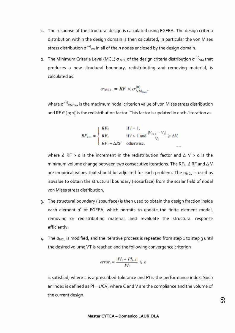
1. The response of the structural design is calculated using FGFEA. The design criteria
distribution within the design domain is then calculated, in particular the von Mises
stress distribution σ (n)VM in all of the n nodes enclosed by the design domain.
2. The Minimum Criteria Level (MCL) σ MCL of the design criteria distribution σ (n)VM that
produces a new structural boundary, redistributing and removing material, is
calculated as
where σ (n)VMmax is the maximum nodal criterion value of von Mises stress distribution
and RF ∈ ]0; 1[ is the redistribution factor. This factor is updated in each i iteration as
where Δ RF > 0 is the increment in the redistribution factor and Δ V > 0 is the
minimum volume change between two consecutive iterations. The RF0, Δ RF and Δ V
are empirical values that should be adjusted for each problem. The σMCL is used as
isovalue to obtain the structural boundary (isosurface) from the scalar field of nodal
von Mises stress distribution.
3. The structural boundary (isosurface) is then used to obtain the design fraction inside
each element de of FGFEA, which permits to update the finite element model,
removing or redistributing material, and revaluate the structural response
efficiently.
4. The σMCL is modified, and the iterative process is repeated from step 1 to step 3 until
the desired volume VT is reached and the following convergence criterion
is satisfied, where ε is a prescribed tolerance and PI is the performance index. Such
an index is defined as PI = 1/CV, where C and V are the compliance and the volume of
the current design.
Master CYTEA – Domenico LAURIOLA
59

Figure 24: Flowchart of iso-stress driven ESO using isosurfaces
3-1-8 Tree-Inspired Optimization
Often, nature became an inspiration. Combined with mathematic could represent an
efficient way to generate forms for the architecture. The irregular non-Euclidean geometry
of natural trees has been now possible to explain through mathematics by the concept of
complex, non-linear and fractal geometries (Casti, 1989).
From the prehistoric age trees and plants had inspired the architecture. Since far past,
architects and constructors attempted to mimic one of the most relevant aspects of tree
like shapes, i.e. their structural and mechanical features, by frequently applying and
developing specific mathematical concepts.
Fractal geometry, a branch of mathematics developed in the 1970s studies abstract
configurations characterized by self-similarity patterns and recursive growth (Mandelbrot,
1982). Although, from the mathematical point of view, fractal objects are sets that have
fractional dimension so that they are intermediate objects between one and two
dimensional shapes or two and three dimensional forms (Falconer,2003), but in the general
sense fractal objects show the properties of being exactly or nearly the same at every
progressive scale.
Master CYTEA – Domenico LAURIOLA
60

Every natural object can be called an “approximate fractal” or “statistical fractal”.
Mathematical property for generating fractals is known as iteration, recursion and
subdivision through the automated process of Iterated Function System (IFS). Fractal
geometry of nature has a connection with nature’s structural and mechanical behaviour.
However, there is a recent debate about the fractal geometry and its definition to explain
the form and the pattern of nature. Bejan (2000) critically argues in his “constructal law”
that is the “laws of thermodynamics” which govern the geometry and form of the natural
objects, and there is no functional connection between nature’s forms and fractal geometry.
Nowadays, a procedural generative approach based on a composition of mathematical
functions can be practiced by using the advantages of contemporary computer technology
for connecting the fractal concept with architecture (Huylebrouck and Hammer,2006).
Figure 25: Fractal tree generation by using Iterated Function System (IFS) as an algorithmic code in the
computer.
Trees with their branches are one of the finest examples of nature’s approximate fractals
that are self-similar in pattern and highly irregular. The explanation of this forms is basically
searching functionality. The constantly searching of the sun radiation, its biological needs,
searching for water and fluids, makes its shape. It seems possible that the branching
patterns of trees are governed by opposing tendencies which are analogous to minimum
energy expenditure and uniform energy utilization. In the case of trees, the minimum
energy expenditure involves minimizing the total length of all branches and stems, while
the uniform energy utilization might concern providing a photosynthetic surface which
tends to attain the most efficient use of sunlight under certain constraints. From a structural
point of view, its form, is related with the mechanical aspect of tree’s structure.
The loads that affect a tree can be external and internal: wind is the most relevant and axial
compression due to its weight. To allow the uniform distribution of stress when it change
Master CYTEA – Domenico LAURIOLA
61

from tensile at the convex side to compressive at concave side and to prevent component
parts from slipping on shear-loaded interfaces, trees optimize their shape to follow this
structural demand. The sway of a tree is not harmonic under the wind load but is more
complex due to the dynamic interaction of branches. The group of complex patterned
branches generate a dynamic damping that reduce dangerous harmonic swat motion and
then minimizing the loads and the mechanical instability. Besides, higher fractal dimension
of branches helps to increase the drag forces and frictions in trees, thus lessens the wind
velocity on its path especially during storms(Kangetal.,2011).
Therefore, every treehas to allow the growth of his branch to capture the sun radiation. To
reduce the weight of the branches, trees manage the branches’ lengths with a size
optimization. With the water searching trees extends its roots. Those roots allow to prevent
the overturning stabilizing the trees over loads actions.
Figure 26: a) Schematic wind forces acting on the initial shape of the tree; b) schematic gravity forces acting
on a deformed shape; c) basal and internal bending moments in each element.
There are a lot of examples reproducing the trees shapes over the past.
Figure 27: a) Ancient Egyptiancolumns inspired by a bundle of papyrus plants in Luxor Temples, Egypt, built in
1400 BC; b) ancient rock-cut columns with lotus capitals in Ajanata caves in India build in 200 BC.
Master CYTEA – Domenico LAURIOLA
62

Figure 28: a) Fan vault in the Chapel of King’s College, Cambridge; b) schematic diagram of stresses in fan
vaulting.
Figure 29: a) Gothic ribbed vault; b) the web of the vault is cut into strips which are analysed as 2D arches
(Wolfe, 1921).
Master CYTEA – Domenico LAURIOLA
63

Figure 30: a) Grand Palais in Paris built in 1900; b) Entrance gate of Paris Metro design by Hector Guimard in
1900.
Figure 31: a) Umbrella structure of Skovshoved Petrol Station, Denmark, 1936; b) Mushroom umbrella
structures, Baroni, 1938.
Figure 32: a) Structural trees in Stuttgart Airport Terminal, Stuttgart, 1991; b) Schematic form diagram of
Stuttgart Airport dendriforms.
Master CYTEA – Domenico LAURIOLA
64

In the 21st century, the computer supported algorithmic and parametric technique has
advances the design and construction of dendritic structures. Every function can be
parametrized by using an algorithm: branching numbers, angles, lengths etc. apart from
IFS, L-System is a digital generator algorithm which is based on the parallel rewriting
system, a type of forma grammar, that can potentially produce natural fractals.
L-system was developed by Aristid Lindenmayer in 1968 and can reproduce the plant
growth to generate forms and shape to utilize in to the architecture.
Figure 33: a) Qatar National Convention Center (2011)
Master CYTEA – Domenico LAURIOLA
65

Figure 34:Topology optimization and size optimization for form finding of a 50 m long bridge and its shelter,
inspired by the tree’s organic form (Frattari et al., 2013)
Master CYTEA – Domenico LAURIOLA
66

Chapter 4
Applications of topology optimization in
architectural design
Among the different methods devoted to solve the problem of topology optimization of
continuous structures, the use of evolutionary topology optimization methods in the
context of architectural design is investigated in this work. Evolutionary topology
optimization techniques are redefining architectural practice providing structurally sound
and aesthetically pleasing architectural designs, which commonly mimic nature´s own
evolutionary optimization process. These techniques provide architects with a powerful tool
to integrate function and form in a synergistic way.
There are many commercial software that use density. In fact, density methods software
works perfectly with mechanical applications to reduce the materials losses and to optimize
the industrial manufacturing process economy.
4-1 A form finding tool for evolutionary topology optimization
One of the advantage of the evolutionary methods (ESO, BESO, MESO etc.) is that are
easily implemented and connected with a lot of commercial FEM software like ABAQUS,
NASTRAN or ANSYS.
The first attempt was make with a combination of commercial software to integrate its
capacities and reduce some problems. The ANSYS software solves the equilibrium
Master CYTEA – Domenico LAURIOLA
67

equations and the MATLAB code receives the solved structure to optimize the 2D
topologies.
ESO optimization has different parameter to deal with such as: the evolutionary ratio (RR),
the increment in the evolutionary ratio (∆R), the minimum volume change between two
consecutive iterations (∆V), the target volume (V*). Apart from that, the mesh, loads and
boundary conditions, needed for the Finite Element Analysis of the continuum structures
are also required.
In the algorithm workflow is possible to see how optimization process (Figure 36: ESO
implementation – MATLAB-ANSYS), settled up with the parameters just shown, receives the
design geometry from ANSYS, and starts the iterative process to determinate which
elements follow the tension criterion established. When each element satisfies the criterion
condition, the iterative process is stopped and the final topology is shown.
Figure 35:Some results of MATLAB implementation
The PI parameter is a function of the tensions, the elements’ volume, the applied forces and
characteristic distance related as the following equation:
𝑃𝑃𝑃𝑃 =1𝐹𝐹𝐹𝐹
𝜎𝜎 𝜌𝜌𝜌𝜌 = ∑ 𝜎𝜎𝑒𝑒𝜌𝜌𝑒𝑒𝑁𝑁𝑒𝑒=1
𝐹𝐹𝐹𝐹𝜌𝜌
Master CYTEA – Domenico LAURIOLA
68

Figure 36: ESO implementation – MATLAB-ANSYS
Master CYTEA – Domenico LAURIOLA
69

4-2 Tool validation through academic examples
The tool just explained on 4.1 is applied to some academic examples to show how does it
work and how is possible exchange information between the commercial software and the
MATLAB code to evaluate some topologies.
4-2-1 Fixed board bridge with uniform vertical force
In this case, the ESO method just introduced, has been used to search the optimum design
for a bridge under a uniform vertical force. The domain length is 180 m, the height 60m and
thickness 300mm. The FEA mesh is formed by 24300 elements (90x270). The elements
below 26 meter are considered no design space area. PI parameter is established with L =
180.000 mm and F = 45.000 KN.
Figure 37: Design bridge
Figure 38Error! Reference source not found.shows the optimum topologies that have been
calculated. The maximum number of stable states, before the total removal of the
elements’ structure, is 102. The minimum value of Performance Index has been achieved
with stable state 24 (PI = 10.056).
Master CYTEA – Domenico LAURIOLA
70

(a) SS=6; PI=11.8346; V/V0=0.9728. (b) SS=18; PI=11.2604; V0=0.7421.
c) SS=20; PI=10.0794; V/V0=0.6128. (d) SS=21; PI=10.0809; V0=0.6128.
(e) SS=24; PI=10.0565; V/V0=0.3919; (f) SS=30; PI=10.1458; V0=0.2948;
(g) SS=65; PI=10.0389; V/V0=0.1516; (h) SS=85; PI=11.0910, V0=0.1408.
Figure 38: Optimum topologies with different stable state
Master CYTEA – Domenico LAURIOLA
71

Figure 39: Performance Index Vs Number of stable state
Figure 39shows how PI number change with every stable state reached by the structure.
The minimum value of PI is 10.0565 reached by the stable state nº 24 with a volume ratio of
V/V0 = 0.3919. The value of PI decreases until stable state nº 10 (Figure 38.c.). at the state nº
10 the number of holes’ structure change, passing from 23 to 22, so it produces an inversion
of the curve like Figure 39.After that, the PI keep coming down until reaches its minimum at
the SS=24. From this point is undergoing to increase because of holes disappearing. At the
state 30 y 65 with V/V0 = 0.2948 and V/V0 = 0.1516 respectively, the curve changes because
of the holes of the structure.
The Figure 38.h) represent the optimum design before the completely vanishing of the
elements totally. It represents the known structural system for the arch and shackle. The
final number of holes is 12.
Master CYTEA – Domenico LAURIOLA
72

4-2-2 Optimum design topology with ESO method for traction and compression
structures
Xie et al. (2005) use the classical ESO with Von Mises stress as criterion to analyse the
suspension model that Antonio Gaudí used 100 years ago. This suspension model is based
on Hooke’ studies.
Figure 40: Poly-funicular miniature design by Gaudí – Sagrada Familia Museum – Barcelona
To obtain an only-compression structure, those elements with compression value higher
will be erased. The less traction value elements will be erased too. Von Mises criterion is no
used and it’s considered just the maximum principal tension in each element.
• Tension criterion 1: σe = σ11
• Tension criterion 2: σe = σ11 + σ22 +σ33
• Compression criterion: σe = - σ11 - σ22 -σ33
Master CYTEA – Domenico LAURIOLA
73

Figure 41: Design domain (a), ESO topologies obtained from a traction load case (catenary)
(a) SS=5; PI=0.4427; V/V0=0.7292; (b) SS=12; PI=0.2379; V0=0.422;
(c) SS=30; PI=0.0866; V/V0=0.1563; (d) SS=79; PI=0.0325;V0=0.0618;
Figure 42:ESO topologies structure obtained from only-traction criterion with dead load case only.
Master CYTEA – Domenico LAURIOLA
74

The Figure 41 and Figure 42show the topologies obtained from a structure with dead load
case. Initial domain is a 200x100 mm rectangle and the mesh is 200x100. For the PI
parameter, can use a longitude L=100 mm and as load F= 1529 N. The chosen criterion is the
“tension criterion 2”.
• Basic domain with foundation restrictions under self-weight load and isolated
forces. (Xie et al.).
This example analyses an ESO method with compression criterion for a 3D structure. The
initial domain are some cubes like the Figure 44.
Figure 43: Performance Index and Volume Vs number of steady stable.
• Basic domain with foundation restrictions under self-weight load and isolated
forces. (Xie et al.).
This example analyses an ESO method with compression criterion for a 3D structure. The
initial domain are some cubes like the Figure 44.Model dimension are 60x60 m and 130 m
height. The isolated forces are 1000 MN and 200 MN and are too big for the model. This
reason for that is to make, the gravity influence, lower than the forces because the gravity,
in the model, is the predominant load condition for the real model.
Master CYTEA – Domenico LAURIOLA
75

(a) Gravity + Isolated forces (b) Domain
Figure 44: Initial design domain
a) Isolated forces and self-weight load case model
(a) Design domain (b) SS=20; PI= 46.50; V0=0.32
(c) SS=6; PI= 114.19; V/V0=0.89 (d) SS=26; PI= 36.15; V0=0.19
Master CYTEA – Domenico LAURIOLA
76

(e) SS=14; PI= 70.97; V/V0=0.55; (f) SS=30; PI= 33.13; V/V0=0.16
Figure 45: Topology evolution.
Figure 46: Topology view SS= 25.
Master CYTEA – Domenico LAURIOLA
77

Figure 47: Compression criterion
The elements near the force application point are highly compressed and they are the less
affected by the evolution process. It’s really interesting see how, on the perimeter, near the
pillars, the structure evolves like an arch.
Figure 48: Arch formation near the base of the pillars.
If the structure keeps evolving, until the V/V0 = 0,16 ratio, the perimeter of the pillars adopts
an arch form. The structure evolves to an only compression topology.
Master CYTEA – Domenico LAURIOLA
78
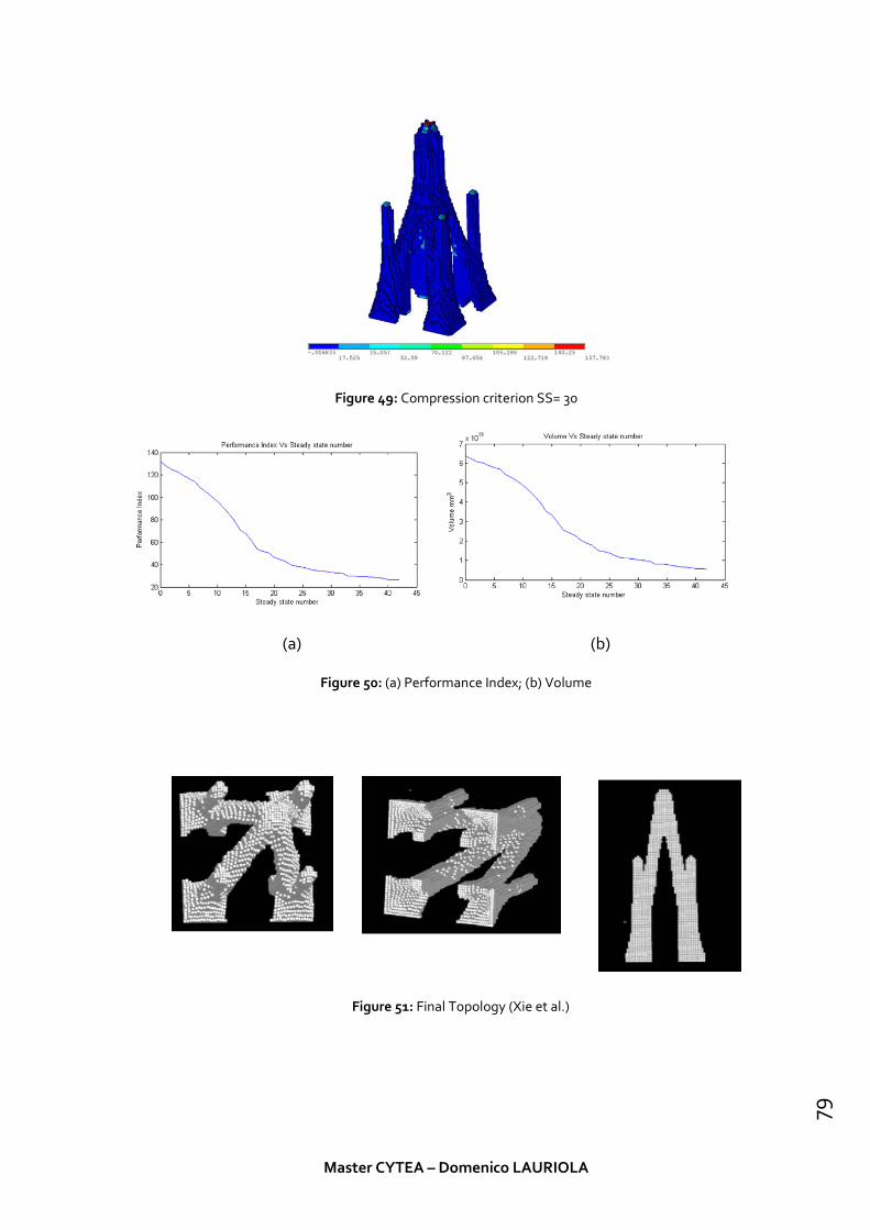
Figure 49: Compression criterion SS= 30
(a) (b)
Figure 50: (a) Performance Index; (b) Volume
Figure 51: Final Topology (Xie et al.)
Master CYTEA – Domenico LAURIOLA
79

b) Isolated forces and self-weight load case model
This model it’s exactly the same of the last one. The only thing that change is the gravity
load case in the vertical direction.
(a) Design domain (b) SS=9; PI= 80,37; V0=0.8743;
(c) SS=22; PI= 50.31; V/V0=0.6491; (d) SS=37; PI= 16.18; V0=0.3071;
(e) SS=38; PI= 8.65; V/V0=0.2165; (f) SS=56; PI= 4.34; V0=0.14;
Figure 52: Topology evolution.
Master CYTEA – Domenico LAURIOLA
80

Figure 53: Criterion Compression SS= 59
Figure 54: Topology view ss= 59
(a) (b)
Figure 55: (a) Performance Index; (b) Volume
For this load case, the final ratio is V/V0= 0,14. If we compare the two load cases models, the
results are really similar. The topology of the final optimized structure is highly influenced
by the load case, so the most important thing is to correctly load the model.
Master CYTEA – Domenico LAURIOLA
81

Master CYTEA – Domenico LAURIOLA
82

4-3 Applications to architectural design
Trying some different way to optimize topologies, the ESO methods offers a lot of ways to
approach the problem.
Every structure that will be described in this section has the same parameters according to
the ISO-ESO optimization described in to 3.1.7 section. When the parameters change, the
section will inform which parameters are going to be used.
• Young’s module (Design zone) = 30000
• Young’s module (No Design zone) = 30
• Poisson’ ratio= 0.3
• R Fo = 0.01
• ΔRF= 0.01
• ΔV = 0.01
• Maximum number of iteration = 3000
• FEA tolerance= 1 x E-8
The used criterions are:
1. Von Mises equivalent stress;
2. Only-Compression stress;
4-3-1 One column ribbed floor case
As previously described, Nervi was one of the first that has tried to optimize the traditional
structural types. He used the isostatic lines to design structural floor because, when the ribs
in a floor are aligned to the isostatics, the floor is more efficient with the same load and
support conditions.
Obviously, these kinds of floors are more efficient that bidirectional standard floors, but, for
the architectural uses, probably is not the best choose (continuum roof surface,
Master CYTEA – Domenico LAURIOLA
83

soundproofing etc.) and, most important, the reinforced concrete probably is not the best
way to produce the efficient ribbed floor.
In this example, the purpose is found which criterion shows the best efficient path to
optimize a topology to create some useful space.
The design domain is represented by a square of 2,5 x 2,5 meters with a central pillar. The
0,06 meters offset of the square border is a “no design” zone. The square height is 0,4
meters.
Figure 56: Design domain
1. Von Mises equivalent stress criterion
So starting from the design domain (84Figure 56) and its possible function to create a space
like some kind of public stairs roof or an isolated protection for a bench into a public park,
the topology evolution is shown as the different stage of the optimization process.
Optimization stage n. 15 Optimization stage n. 30
Master CYTEA – Domenico LAURIOLA
84

Optimization stage n. 45 Optimization stage n. 60
Optimization stage n. 80 Optimization stage n. 95
Optimization final stage n. 106
The final stage, Figure 57, is configuring an optimized topology that describe a typical
framework. It is possible to identify how the materialdistributionis disposed along the first
and the second main direction. The third main direction is revealed by the material around
the constraint.
It is possible to see how the main stress trajectories guide the configuration of the topology
instead of the loads or material stiffness. According to Chen and Li (2010), stress lines are
just affected by the geometry of the design space and the properties of the boundary
conditions.
Master CYTEA – Domenico LAURIOLA
85

Figure 57: Top view – Von-Mises case
An alternative solution was found by Nervi at his Gatti Wood Factory’ ribbed floor (Figure 58).
The topology in this case is a little bit different because of Nervi’ isostatic method process
and because of the employ of its “ferrocemento” material. But in any case, the Nervi’
solution defines three principal directions where he hasspread out the ribs.
Figure 58: Gatti Wood Factory ribbed floor
Master CYTEA – Domenico LAURIOLA
86

2. Only-Compression stress criterion
If the criterion change the topology is going to change the materialdistribution. As
displayed in the following pictures, the criterion changes the evolution of the topology. If
the Von-Mises criterion shows a topologywhere the main directions are clearly visible, the
compression criterion shows a different path and a different elements distribution.
Since the optimization starts is clearly visible that the material density is higher than the
Von-Mises criterion one because the elements can have just one kind of stress instead of
three.
Optimization stage n. 10 Optimization stage n. 20
Optimization stage n. 30 Optimization stage n. 40
Optimization final stage n. 54
The final stage, Figure 59, is configuring an optimized topology that looks like a Catenary
distribution for each element.
Master CYTEA – Domenico LAURIOLA
87

Each criterion produces a different topology according to its design.From the point of view
of the sustainability, the material usage is higher than the first criterion topology and, the
structure has a fragile capability to react to the load actions.
Figure 59: Top View - Only compression case
Master CYTEA – Domenico LAURIOLA
88

Master CYTEA – Domenico LAURIOLA
89

4-3-2 Four columns ribbed floor case
In this second case of study, the ribbed floor has 4 constraints represented by the four
columns atFigure 60. This kind of topology, as shown on previous picture, can cover any
kind of space but in this case I have supposed a conference room.
The design domain is represented by a square of 2,5 x 2,5 meters with four corner pillar. The
0,06 meters offset of the square border is a “no design” zone. The square height is 0,4
meters.
Figure 60: Design Domain
1. Von Mises equivalent stress criterion
As the one column’ ribbed floor case, the Von-Mises criterion shows the typical main
direction distribution of the elements.
Optimization stage n. 15 Optimization stage n. 30
Master CYTEA – Domenico LAURIOLA
90

Optimization stage n. 45 Optimization stage n. 60
Optimization final stage n. 80
The final configuration,Figure 61 ,is characterized by a typical structural configuration of the
vertical element. The trellis configuration of the topology representswhere the structure
need the material to resist but, depending on the chosen material, the topology could
change.
The central distribution of the material creates a very interesting effect that could generate
a nice combination of aesthetic and efficiency for the function of the structure.
The research of this combination is, probably, one of the biggest problem for the
architectural structure. A problem that, at this moment, does not have reached a
compromise between the aesthetic and efficiency (economical perspective).
Master CYTEA – Domenico LAURIOLA
91

Figure 61: Top view - Von-Mises case
Figure 62: Palace of Labour’ ribbed floor; a) photo b) isostatics lines
The Nervi’s approach pushed him on the same path to find the perfect combination of
aesthetic and efficiency. In fact, Palace of Labour(Figure 62), points to the same elements
distribution.
The differences between the Nervi’s design approach and the topology design approach,
lies into production procedures used to assemble the roof. So, the optimization process
probably can be more focused on the production procedures that on the tension criterion. In
Master CYTEA – Domenico LAURIOLA
92

fact, if the principal directions do not depend on material, the difference between a
hypothetical efficient structure and a real efficient one is the manufacturing process.
Master CYTEA – Domenico LAURIOLA
93

2. Only-Compression stress criterion
In this study case, the criterion displays a bigger material density too and some less
aesthetical configuration.
Optimization stage n. 5 Optimization stage n. 10
Optimization stage n. 15 Optimization stage n. 20
Optimization final stage n. 30
The elements are organized according to a catenary distribution. The principal diagonal
elements are in the same position of the Von Mises example.So, the Von-Mises criterion
generates more efficient structure that can resist to different load cases. It is also possible to
observe that the iteration number is bigger at Von-Mises criterion.
Master CYTEA – Domenico LAURIOLA
94

Master CYTEA – Domenico LAURIOLA
95

Master CYTEA – Domenico LAURIOLA
96

4-3-3 Computer-aided form finding and optimal design of branching structures
– parking roof example
In the next example, the ISO-ESO optimization, was used to describe a form-finding process
with a simple parking roof example. The design domain is composed by two parallel wall of
0,6 x 6 meters with a 6 x 1 meter rectangle roofon the top. The walls are distant from each
other by 4,4 meters. The “No design zone” (red colour) is the highest part of the roof (0,1
meter height). This will allow the load distribution without affect the element distribution
on the top.
Figure 63: Parking roof design domain
1. Von Mises equivalent stress criterion
The first stages display how the optimization start from the horizontal element and is
progressively removing material till the only horizontal connection is the “no design zone”.
The most interesting thing to observe is the amount of the material removed from the
design domain to generate the topology with the better stiffness configuration of the
elements.
Optimization stage n. 15 Optimization stage n. 30
Master CYTEA – Domenico LAURIOLA
97

Optimization stage n. 45 Optimization stage n. 60
Optimization stage n. 70 Optimization stage n. 80
Optimization final stage n. 95
It’s look like a real branch distribution according to the nature’ law. In this case, the criterion
used, just configure the mechanical response of the material, not its thermo-dynamical
optimization to the contour conditions (Bejan,2000).
Master CYTEA – Domenico LAURIOLA
98
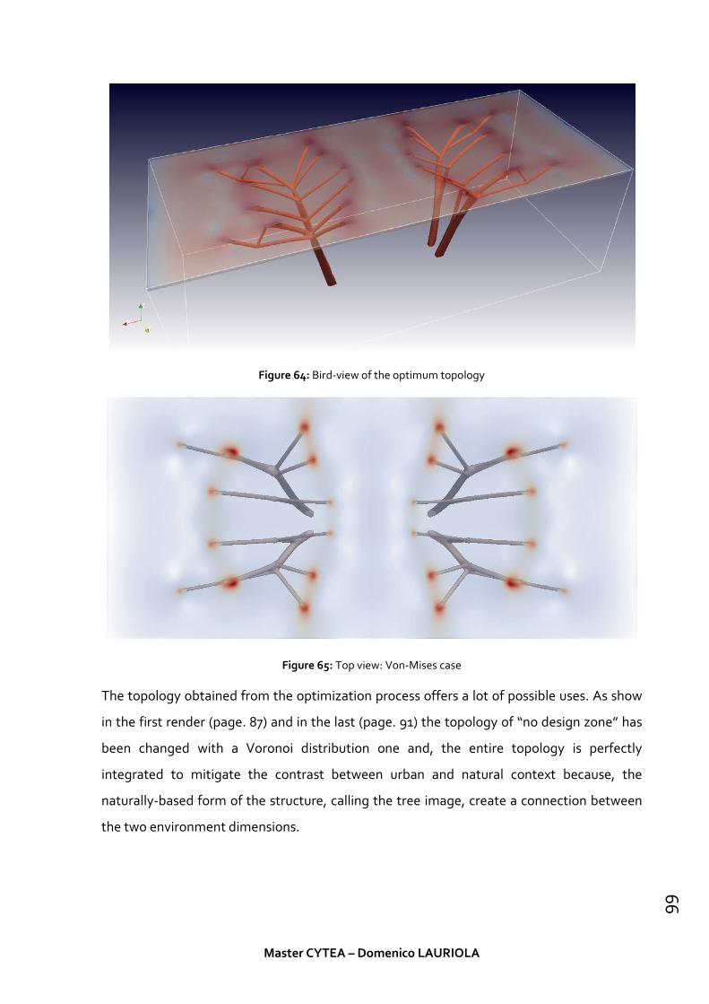
Figure 64: Bird-view of the optimum topology
Figure 65: Top view: Von-Mises case
The topology obtained from the optimization process offers a lot of possible uses. As show
in the first render (page. 87) and in the last (page. 91) the topology of “no design zone” has
been changed with a Voronoi distribution one and, the entire topology is perfectly
integrated to mitigate the contrast between urban and natural context because, the
naturally-based form of the structure, calling the tree image, create a connection between
the two environment dimensions.
Master CYTEA – Domenico LAURIOLA
99

Master CYTEA – Domenico LAURIOLA
100

2. Only-Compression stress criterion
Optimization stage n. 10 Optimization stage n. 20
Optimization stage n. 30
Optimization final stage n. 45
The only-compression case obtains almost the same topology compared with Von-Mises
case. Only the density of constraints of the horizontal roof changes. This probably is caused
by the principal stress direction that is the most relevant due to its load case. So, probably,
the two criterion converge to an “optimum” which means the best configuration of a
structure with vertical load.
Master CYTEA – Domenico LAURIOLA
101

Figure 66: Bird-view of the optimum topology
Figure 67: Top view - Only compression case
Master CYTEA – Domenico LAURIOLA
102

Master CYTEA – Domenico LAURIOLA
103

4-3-4 Topology Optimization – Bridge Example
In the last example, the bridge example, the domain is a 12 x 2 meters isostatic rectangle.
The design zone (green one) is an inset of 0,2 meters. The “No Design Zone” (red one) is just
the rest of the domain. The load is a vertical uniform distribution load. Some ISO-ESO
parameters change from initial configuration to simulate a different material (Steel):
• Young’s module (Design zone) = 210000
• Young’s module (No Design zone) = 210
Figure 68: Bridge design domain
Master CYTEA – Domenico LAURIOLA
104

1. Von Mises equivalent stress criterion
Optimization stage n. 15 Optimization stage n. 30
Optimization stage n. 45
Optimization final stage n. 60
This example shows how optimize the trellis typical configuration of a steel bridge. The
most important result of this optimization, is the possibility to reduce the material usage
Master CYTEA – Domenico LAURIOLA
105

and then, reduce the costs of the entire structure.Is the perfect example of a common
structure that can be replaced with the modern technologies like the industry
manufacturing processes.
One possible solution is to apply a manufacturing method called 'sand casting', which is
applied in the metal industry, mainly. It is characterized by using a mold made of sand and
stabilized with either clay, another bonding agent, or a vacuum. Stabilizing the sand by
means of a vacuum allows the sand to assume more complex shapes than its own angle of
repose will support. Major advantages of this technique are reusability, the easily mold
removing process, and adaptability. These advantages mean that the formwork cost may
be reduced severely when producing topology-optimized, especially since they have a high
rate of repetition in most multi-story buildings. The reduction of waste of mold material is
also a sustainable consequence.
The render at page 98 shows a possible path to integrate the structure into a natural
context.
Master CYTEA – Domenico LAURIOLA
106

Master CYTEA – Domenico LAURIOLA
107

Master CYTEA – Domenico LAURIOLA
108

Chapter 5
Conclusions
At the end of this work, several conclusions can be drawn. First of all, it’s clearly visible that
a lot of important architect and engineer had discovered many ways to optimize the design
workflow without using a computational architecture.
Every single author had discovered his own personal way to optimize a structural design
workflow because of the experiences were so different between them.
With the help of the powerful processing units (CPU, GPU, etc.) these ways are logically
going to increase the possibility of architects and structural practitioners involved into the
design workflow. Each designer has the possibility to choose one of the analysed methods
to reach better performance according with the structure that he has to design.
Then, starting from the complexity of the architecture, passing through the efficiency of its
structure, it’s possible to explain how the architect and the engineer cannot work separately
to generate the perfect balance between form and efficiency.
With this constant feedback process from engineers and architects, the topology
optimization helps to reduce the material waste too like the way illustrated on Chapter 4.
Depending on loads applied, the topology optimization can reduce the material used
between 40 – 70 %. So, efficiency could be sustainable and reach the aesthetical
equilibrium at the same time.
The form and the design cannot live separately like the aesthetic and the functionality.
Everything needs to work together to generate “Architecture”.
In the future, the possible developments could be:
• Reduce the computational cost for topology optimization process. Use the newest
Graphics Processing Units to reduce time and obtain more exact topologies. This will
Master CYTEA – Domenico LAURIOLA
109

help the design process and the evaluation of a single topology between architects
and engineers.
• Improve the ESO optimization with a graphics interface that can work with the BIM
methodology and with the most important structural analysis software platform.
• Head the computational architecture to the way of the sustainability. It means
include the law of the thermodynamic into the solving algorithm like the natural
beings does.
• Introduce architectural constraints within the topology optimization which provide
the possibility for the user to interfere on the optimization process by supplying
information about his personal taste.
5-1 SWOT Analysis
To compare the technical and qualitative points of view, the SWOT analysis can analyse the
Strengths, the Weaknesses, the Opportunities and the Threats of the design methodology
just described.
• STRENGHTS
The ISO-ESO method has a little bit faster processing time than the other ESO methods and
offers results really accurate (very little grid elements).
The strengths of 'sand casting’ formwork can be compared to other production methodsfor
reinforced concrete. As mentioned in earlier in this chapter, the advantages of a'sand
casting’ formwork include the design freedom, a zero-degree draft, thin walls, ahigh surface
finish, tight tolerances, an unlimited pattern life, and a reusable sandcore. Barring the
additional research that is still required, the method has thepotential to be relatively cheap
for very complex geometry, as it can be applied ina low-tech fashion. The combination of
these strengths is what makes 'sand casting’ formwork unique.
• WEAKNESSES
Master CYTEA – Domenico LAURIOLA
110

Although the Evolutionary Topology Optimization techniques provide architects with a
powerful tool to integrate function and form in a synergistic way, the resolution of high
resolution models to obtain proper designs may be challenging both in computational and
memory consumption terms. To alleviate this issue, massively parallel architectures such as
GPU devices can be used. In this work the ISO-ESO method was been processed on NVIDIA
“Pascal” architecture.
Bending,placing, and binding of the reinforcement can be a problem, however.The
bendingis challenging, because of the complex shape of the ribs. Placing and binding of
thereinforcement might also be complicated, as the formwork is relatively
vulnerable(Huijben, 2014).Puncturing of the film, or making an unwanted imprint by
workersare reasonable risks. After hardening, transport to the building site and
placementof the prefab segments should be similar to other prefab systems.
• OPPORTUNITIES
There is a lot of interest in topology optimization and this can produce some entrance into
the market. Because of the material waste reduction, the sustainability is clearly
incremented and this can produce some benefits margin for its production. The aesthetics
factor makes a real big difference from a standard no efficient structure and the optimized
one. A nice topology-optimized structure can be more attractive and it can be easily
introduced in the urban context.
• THREATS
The first threat is man-hour cost that if remains high, can reduce the benefits of the material
use reduction and so, can make the topology-optimized structure out of the market.
Other threat can be the evolution of other manufacturing process that can reduce the
flexibility of the optimized solutions to make easier and less efficient and complicated
topologies.
So, looking at SWOT analysis the better way to increase the use of this method is the search
of some material (probably concrete based) reinforced with polymeric fibre that can reduce
the scale problem. In the other way, the manufacturing of these structure is the most
important orientation for the design process. The use of new manufacturing process has to
be always oriented to the flexibility and the reproducibility of the final solution.
Master CYTEA – Domenico LAURIOLA
111

The SWOT analysis has shown that, although topology optimization has been recognized as
a powerful computationaltool, especially in automotive and aircraft industries, it has not yet
succeeded in transforming the construction industry to the same extent. This can be
attributed to the one-off nature of building structures, which reduces the impact of weight
savings in the cost in comparison to mass productions.
Furthermore, in the era of sustainable development the efficient use of materials and the
environmental considerations have become a primary concern which motivates the use of
advanced topology optimization in the architectural and structural engineering
communities.
As the topology optimization process is so important to reduce weight for the aeronautics
industry, optimizing branches spatial configuration is fundamental for the trees life, so
environmental considerations and sustainability will integratethe topology optimization
techniques into one-off nature architectural and structural design process.
Master CYTEA – Domenico LAURIOLA
112

Bibliography
1) Advanced Topology Optimization Methods for Conceptual Architectural Design. Niels Aage, Oded Amir, Anders Clausen, Lior Hadar, DanaMaier,Asbjørn Søndergaard. 2014. 2014, Springer International Publishing Switzerland 2015.
2) Alessandro BEGHINI, Lauren L. STROMBERG, William F. BAKER, Glaucio H. PAULINO, Arkadiusz MAZUREK. A New Frontier in Modern Architecture: Optimal Structural Topologies.
3) ANTON OLASON, DANIEL TIDMAN. 2010. Methodology for Topology and Shape Optimization in the Design Process. Master’s Thesis in the Master’s programme Solid and Fluid Mechanics. 2010.
4) Antonio Tomas, Pascual Martí-Montrull. 2010.Optimality of Candela's concrete shells: A study of his posthumous design. 2010.
5) APPLICATIONS OF TOPOLOGY OPTIMISATION IN STRUCTURAL ENGINEERING. James J. Kingman, Konstantinos Daniel Tsavdaridis, Vassili V. Toropov. 2014. 2014.
6) ENGINEERING DESIGN USING EVOLUTIONARY STRUCTURAL. M.J. García, O.E. Ruiz and G.P. Steven.
7) Finite Element Analysis of Dome of a Home Subjected to Hurricane. Habib Sadid, Niraj Ghag.
8) Form finding for complex structures using evolutionary structural optimization method. Y.M. Xie, P. Felicetti, J.W. Tang, M.C. Burry. 2004. 2004.
9) FRATTARI, LUCA. THE STRUCTURAL FORM: Topology Optimization in Architecture and Industrial Design. Ph.D. in: Architecture, Environment and Design. s.l. : University of Camerino.
10) Frutos, Jesús Martínez. 2010. Métodos evolucionarios para la optimización de topología de estructuras continuas. 2010.
11) GPU Acceleration for Evolutionary Topology Optimization of Continuum Structures. Jesús Martínez-Frutos, David Herrero-Pérez. 2016. 2016.
12) Javier Oliva Quecedo, Pablo Antolín Sánchez, Alfredo Cámara Casado, José M. Goicolea Ruigómez. 2010.Finite element model analysis of works authored by Félix Candela. 2010.
13) Jones, Garrett P. 2012. Interoperable Software for Parametric Structural Analysis and Optimization. 2012.
14) Knowledge-based parametric tools for concrete masonry walls: Conceptual design and preliminary structural analysis. Andres Cavieres, Russell Gentry, Tristan Al-Haddad. 2011. 2011.
Master CYTEA – Domenico LAURIOLA
113

15) Lauren L. Stromberg, Alessandro Beghini, William F. Baker, Glaucio H. Paulino. 2011. Application of layout and topology optimization using pattern gradation for the conceptual design of buildings. 2011.
16) M. Victoria, P. Martí, O. M. Querin. January 2009. Topology design of two-dimensional continuum structures using isolines. Computers & structures. January 2009, Vol. 87, 1-2.
17) Massimiliano Savorra, Giovanni Fabbrocino. 2013.Félix Candela between philosophy and engineering: the meaning of shape. 2013.
18) Meisam Abdi, BSc, MSc. 2015. Evolutionary Topology Optimization of Continuum Structures using X-FEM and Isovalues of Structural Performance. Thesis submitted to the University of Nottingham. 2015.
19) O'Sullivan, John. 2011. THE AESTHETICS OF TOPOLOGY OPTIMISATION AND NON-STANDARD ANALYSIS. Master Thesis explanatory document David Rhodes and Regan Potangaroa. 2011.
20) RECENT ADVANCES IN EVOLUTIONARY STRUCTURAL OPTIMIZATION. Y.M. Xie, X. Huang, J.W. Tang and P. Felicetti. 2005. 2005.
21) Sigrid Adriaenssens, Philippe Block, Diederik Veenendaal, Chris Williams. 2014.SHELL STRUCTURES FOR ARCHITECTURE. Form Finding and Optimization. s.l. : Routledge, 2014.
22) Solomita, Pasqualino. 2012. Pier Luigi Nervi architetture voltate. Verso nuove strutture. Phd. 2012.
23) Structural Design in the Work of Gaudi. Huerta, Santiago. 2006. 2006.
24) Structural invention and production process in the Pier Luigi Nervi's work. Ruggieri, Nicola. 2003. 2003.
25) Tang, Jiwu. 2011. Developing Evolutionary Structural Optimization Techniques for Civil Engineering Applications. A thesis submitted in fulfilment of the requirement for the degree of Doctor of Philosophy. 2011.
26) The Ribbed Floor Slab Systems of Pier Luigi Nervi. Allison B. Halpern, David P. Billington, Sigrid Adriaenssens. 2013. 2013.
27) The Structural Conception in Pier Luigi Nervi’s work. Sassone, Mario.
28) Three Resilient Megastructures by Pier Luigi Nervi. Manuel Cresciani, John Forth. 2011. 2011.
29) TOPOLOGY OPTIMIZATION: THE USE OF CUTTING EDGE NUMERICAL METHODS IN TEACHING STRUCTURES TO ARCHITECTS. Dr. Sinead C. Mac Namara, Prof. James K. Guest,. 2012. 2012, American Society for Engineering Education.
30) Tree-inspired dendriforms and fractal-like branching structures in architecture: A brief historical overview. Iasef Md Riann, Mario Sassone. 2014. 2014.
31) Two Hybrid Structures by Pier Luigi Nervi. CRESCIANI, Manuel. 2009. 2009.
Master CYTEA – Domenico LAURIOLA
114

Master CYTEA – Domenico LAURIOLA
115