Mark VII JetWash Self-Serve
45
Part number 6370-0630 Revision 02 September 2010 Mark VII JetWash ® Self-Serve Mark VII Equipment Inc. 5981 Tennyson Street Arvada, Colorado 80003 Tel (303) 423-4910 Fax (303) 430-0139 www.markvii.net Instruction Manual
Transcript of Mark VII JetWash Self-Serve

Part number 6370-0630 Revision 02 September 2010
Mark VII JetWash
® Self-Serve
Mark VII Equipment Inc. 5981 Tennyson Street
Arvada, Colorado 80003 Tel (303) 423-4910 Fax (303) 430-0139
www.markvii.net
Instruction Manual

Part number 6370-0630 Revision 02 September 2010
© 2006 Mark VII Equipment Inc. Mark VII
®, JetWash
®, AquaSpray
®, AquaJet XT
®, SoftWash XT
®, ChoiceWash XT
®, CombiWash
XT®, AquaDri
®, HubScrub
®, Wash Alert
®, WashNet
®, WashTeller
®, are registered trademarks of
Mark VII Equipment Inc.

Instruction Manual JetWash®
6370-0630 Rev. 02 Page 3
Table of Contents
Table of Contents ............................................................................................................ 3
List of Figures ................................................................................................................. 5
Preface ........................................................................................................................... 6
Introduction ..................................................................................................................... 6
Safety Guidelines: ....................................................................................................... 7
Directives de sécurité: ................................................................................................. 9
Specifications and Features .......................................................................................... 11
Standard Features and Equipment ............................................................................ 11
Optional Features and Equipment ............................................................................. 12
Specifications ............................................................................................................ 13
JetWash® Dimensions ........................................................................................... 14
Electrical ................................................................................................................ 14
Air and Water ......................................................................................................... 14
Quick Start Guide .......................................................................................................... 15
Equipment and Operation ............................................................................................. 17
Hot Water Inlet Manifold......................................................................................... 19
Cold Water Inlet Manifold ....................................................................................... 19
Spot Free Water Inlet Manifold .............................................................................. 19
High Pressure Pump .............................................................................................. 19
Outlet Manifolds ..................................................................................................... 20
Pressure/Volume Control ....................................................................................... 20
Chemical Mixing ..................................................................................................... 22
Low-Pressure Product distribution .......................................................................... 22
Weep System ........................................................................................................ 22
Anti-Freeze Injection System ................................................................................. 23
Electrical System .................................................................................................... 23
Bay Equipment .......................................................................................................... 24
Other Equipment ....................................................................................................... 24
Installation ..................................................................................................................... 25
Bay requirements ...................................................................................................... 25
Bay floors ............................................................................................................... 25

JetWash® Instruction Manual
Page 4 Rev. 02 6370-0630
Drains and traps ..................................................................................................... 25
Utilities ................................................................................................................... 25
Underground conduits ............................................................................................ 25
Overhead Booms ................................................................................................... 25
Coin boxes and safe .............................................................................................. 25
Equipment room requirements .................................................................................. 26
Equipment room ..................................................................................................... 26
Bill changers .......................................................................................................... 26
Utilities ................................................................................................................... 26
Venting ................................................................................................................... 26
Drains .................................................................................................................... 26
Pumping Plant Connections....................................................................................... 27
Connecting the manifold for hot water supply ......................................................... 29
Connecting the manifold for cold water supply ....................................................... 29
Connection the manifold for spot free water supply ................................................ 29
Connecting the manifold for weep water supply ..................................................... 29
Electrical Connections ............................................................................................ 31
Connecting the low pressure output lines ............................................................... 32
Installing the Wash Bay Equipment ........................................................................... 33
Equipment installation ............................................................................................ 33
360° Dual Booms ................................................................................................... 34
180° Bubble Brush Boom ....................................................................................... 36
Installing the Foam Generator for the High Pressure Gun...................................... 37
Installing the Bubble Brush Foam Generator .......................................................... 38
Installing the Foam Conditioner Applicator ............................................................. 39
Installing the Coin Box ........................................................................................... 40
Start-up...................................................................................................................... 41
A. Pump oil ............................................................................................................. 41
B. Chemicals .......................................................................................................... 41
C. Water softener ................................................................................................... 41
D. Underfloor heat start-up ..................................................................................... 41
E. Water ................................................................................................................. 41
F. Water heater ...................................................................................................... 41
G. Turn on power ................................................................................................... 41
Instruction Manual JetWash®
6370-0630 Rev. 02 Page 5
H. Coinbox Timers ................................................................................................. 41
I. Pump Plant Systems check ................................................................................. 42
Appendix ....................................................................................................................... 45
A. Approximate Injector Dilution Ratios and Rates Chart ........................................ 45
List of Figures Figure 1, JetWash® Dimensions ................................................................................... 13
Figure 2, JetWash® System, Front View....................................................................... 17
Figure 3, JetWash® System, Back View ....................................................................... 18
Figure 4, Pumping Plant Detail, Front View ................................................................... 20
Figure 5, Pumping Plant Detail, Back View ................................................................... 21
Figure 6, Installation Connections, Front & Top Views .................................................. 27
Figure 7, Installation Connections, Back & Side Views .................................................. 28
Figure 8, Lower Section, Back View .............................................................................. 29
Figure 9, Lower Section, Front View ............................................................................. 30
Figure 10, Electrical Enclosure ...................................................................................... 31
Figure 11, Chemical Tubing Color assignment .............................................................. 32
Figure 12, 360° Dual Boom ........................................................................................... 34
Figure 13, Dual boom mounting .................................................................................... 35
Figure 14, 180° Bubble Brush Boom ............................................................................. 36
Figure 15, HP Gun Foam Generator ............................................................................. 37
Figure 16, Bubble Brush Foam Generator..................................................................... 38
Figure 17, Foam Conditioner Applicator ........................................................................ 39
Figure 18, Coin Box ...................................................................................................... 40
Figure 19, Approximate Injector Dilution Ratios and Rates Chart .................................. 45
JetWash Instruction Manual
Page 6 Rev. 02 6370-0630
Preface The Mark VII Equipment JetWash® self-serve car wash system is designed by operators for operators. Our engineers employ state-of-the-art design and modeling tools with self-serve owners reviewing the results at every step. JetWash® offers more standard features than any other comparably priced unit. The wide range of functions and options, unsurpassed uptime and dependability, and attractive and easy to use in-bay packages are all designed to maximize profit. The JetWash® offers operators and investors ease of service in a compact configuration package designed to fit their needs.
Introduction This manual‟s objective is to provide information regarding the JetWash® self-service system, installation and start-up. Other unique information about this product is also a part of the manual.
The content of this manual is specifically about the JetWash® Pumping Plant. Other equipment, accessories, or parts, which accompany the use of this system, will be mentioned as necessary.
Parts lists for the JetWash® Compact are available separately from this manual.

Instruction Manual JetWash
6370-0630 Rev. 02 Page 7
Safety Guidelines:
Mark VII recommends that these general safety guidelines be followed when working on any Mark VII equipment. These are not all-inclusive safety rules. Caution and Warning icons are used throughout this manual to promote safe work practices.
Turn off the power to machinery, computer, and other electrical equipment prior to working on it, which includes turning off all circuit breakers and following standard lockout/tagout procedures. This may involve disconnecting more than one electrical source.
Never bypass any safety devices such as overloads on motor starters, high limit thermostats on heaters, fuses on computers and transformers.
Always wear safety glasses when working near running equipment.
Never lean or climb on the machinery when it is operating.
Keep your work area clean. Water or soap may cause an employee or customer to slip and fall.
Be aware of the location of eye wash stations.
Handle all chemicals properly. Follow label instructions and always consult the Material Safety Data Sheet (MSDS) before using any chemical. The following chemicals are particularly hazardous even at low concentrations:
Hydrofluoric Acid;
Bromic Acid;
Hydrogen Cyanide;
Hydrochloric Acid;
Chlorinated Solvents;
Ammonium Bifluoride;
Ethonalamine;
D-Limonene; and
Any product with a flash point less than 105 F
Never use a product that contains any of these chemicals in connection with the operation of a Mark VII car wash. This list is not all inclusive.
Always comply with the law and use appropriate personal protective equipment, such as protective gloves, safety glasses, face shields, and respirators, when handling a chemical.

JetWash Instruction Manual
Page 8 Rev. 02 6370-0630
Do not hesitate to contact chemical suppliers, the health department, or the Environmental Protection Agency for more information about any car wash product before using it.
Use approved personal protective equipment for any welding operation.
Sharp edges may be present on sheet metal. Use caution when handling metal parts.
Injection Hazard - Equipment can cause serious injury if the spray penetrates the skin. Do not point the gun at anyone or any part of the body. In case of penetration seek medical aid immediately.
To avoid rupture and injury, do not operate this pump with components rated less than 10,342 kpa (1500 psi) working pressure (including but not limited to spray guns, hose, and hose connections).
SAFETY INSTRUCTIONS
WARNING - WHEN USING ELECTRIC APPLIANCES, BASIC PRECAUTIONS
SHOULD ALWAYS BE FOLLOWED, INCLUDING THE FOLLOWING:
A) READ ALL THE INSTRUCTIONS BEFORE USING THE APPLIANCE.
B) TO REDUCE THE RISK OF INJURY, CLOSE SUPERVISION IS NECESSARY WHEN AN APPLIANCE IS USED NEAR CHILDREN.
C) DO NOT CONTACT MOVING PARTS.
D) ONLY USE ATTACHMENTS RECOMMENDED OR SOLD BY THE MANUFACTURER.
E) DO NOT USE OUTDOORS.
F) TURN THE POWER SWITCH TO THE OFF POSITION WHEN NOT IN USE AND BEFORE SERVICING AND CLEANING.
G) USE ALL APPROPRIATE LOCKOUT/TAGOUT PROCEDURES.
SAVE THESE INSTRUCTIONS.
Instruction Manual JetWash®
6370-0630 Rev. 02 Page 9
Directives de sécurité:
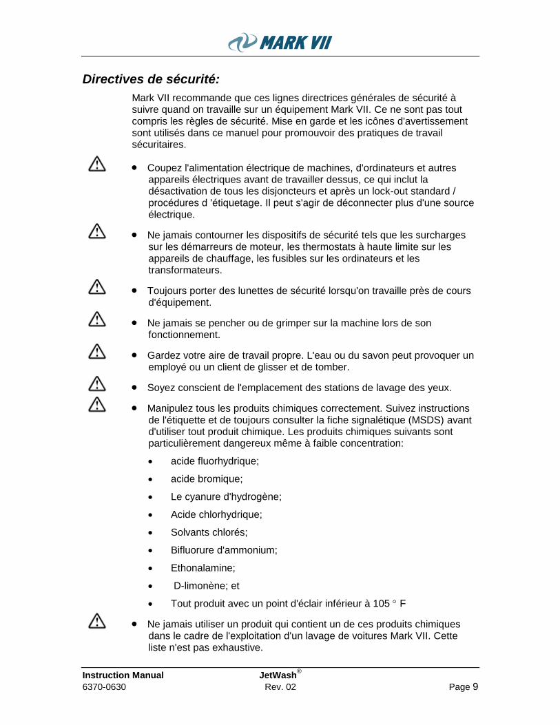
Mark VII recommande que ces lignes directrices générales de sécurité à suivre quand on travaille sur un équipement Mark VII. Ce ne sont pas tout compris les règles de sécurité. Mise en garde et les icônes d'avertissement sont utilisés dans ce manuel pour promouvoir des pratiques de travail sécuritaires.
Coupez l'alimentation électrique de machines, d'ordinateurs et autres appareils électriques avant de travailler dessus, ce qui inclut la désactivation de tous les disjoncteurs et après un lock-out standard / procédures d 'étiquetage. Il peut s'agir de déconnecter plus d'une source électrique.
Ne jamais contourner les dispositifs de sécurité tels que les surcharges sur les démarreurs de moteur, les thermostats à haute limite sur les appareils de chauffage, les fusibles sur les ordinateurs et les transformateurs.
Toujours porter des lunettes de sécurité lorsqu'on travaille près de cours d'équipement.
Ne jamais se pencher ou de grimper sur la machine lors de son fonctionnement.
Gardez votre aire de travail propre. L'eau ou du savon peut provoquer un employé ou un client de glisser et de tomber.
Soyez conscient de l'emplacement des stations de lavage des yeux.
Manipulez tous les produits chimiques correctement. Suivez instructions de l'étiquette et de toujours consulter la fiche signalétique (MSDS) avant d'utiliser tout produit chimique. Les produits chimiques suivants sont particulièrement dangereux même à faible concentration:
acide fluorhydrique;
acide bromique;
Le cyanure d'hydrogène;
Acide chlorhydrique;
Solvants chlorés;
Bifluorure d'ammonium;
Ethonalamine;
D-limonène; et
Tout produit avec un point d'éclair inférieur à 105 F
Ne jamais utiliser un produit qui contient un de ces produits chimiques dans le cadre de l'exploitation d'un lavage de voitures Mark VII. Cette liste n'est pas exhaustive.

JetWash® Instruction Manual
Page 10 Rev. 02 6370-0630
Toujours se conformer à la loi et l'utilisation appropriée des équipements de protection individuelle, tels que des gants de protection, lunettes de sécurité, masques protecteurs, et des respirateurs, lors de la manipulation d'un produit chimique.
N'hésitez pas à contacter fournisseurs de produits chimiques, le département de la santé, ou de l'Environmental Protection Agency pour plus d'informations sur un produit de lavage de voiture avant de l'utiliser.
Utiliser des équipements de protection individuelle pour toute opération de soudage.
Les arêtes vives peuvent être présents sur la feuille de métal. Soyez prudent lorsque vous manipulez des pièces en métal.
Injection de danger - L'équipement peut causer des blessures graves si le jet pénètre dans la peau. Ne pas pointer le pistolet sur quelqu'un ou une partie quelconque du corps. En cas de pénétration de rechercher immédiatement des soins médicaux.
Pour éviter des ruptures et des blessures, ne pas utiliser cette pompe avec des éléments prévus pour moins de 10.342 kPa (1500 psi) pression de travail (y compris mais non limité aux pistolets, le tuyau et raccords).
CONSIGNES DE SECURITE
AVERTISSEMENT - L'UTILISATION DES APPAREILS ÉLECTRIQUES, DES
PRÉCAUTIONS DE BASE DEVRAIENT TOUJOURS ÊTRE RESPECTÉES, Y COMPRIS LES SUIVANTES:
A) LIRE TOUTES LES INSTRUCTIONS AVANT D'UTILISER L'APPAREIL.
B) POUR RÉDUIRE LE RISQUE DE BLESSURE, SURVEILLANCE ÉTROITE EST NÉCESSAIRE LORSQU'UN APPAREIL EST UTILISÉ PRÈS DES ENFANTS.
C) NE PAS TOUCHER LES PIÈCES.
D) UTILISER UNIQUEMENT LES ACCESSOIRES RECOMMANDÉS OU VENDUS PAR LE FABRICANT.
E) NE PAS UTILISER À L'EXTÉRIEUR.
F) METTEZ L 'INTERRUPTEUR SUR LA POSITION OFF LORSQU'IL N'EST PAS UTILISÉ ET AVANT TOUT ENTRETIEN ET NETTOYAGE.
G) UTILISER TOUS LES PROCÉDURES APPROPRIÉES LOCKOUT /TAGOUT.
SAVE THESE INSTRUCTIONS.
Instruction Manual JetWash®
6370-0630 Rev. 02 Page 11
Specifications and Features
Standard Features and Equipment
All Stainless Frame;
Compact Footprint;
Variable Frequency Drive Pump Control;
Direct Drive Pumps;
Giant P220 High Pressure Pumps;
Chemical Injectors;
Lighted Solenoid Plugs;
High Pressure Rinse;
High Pressure Soap;
High Pressure Wax;
Low Pressure Presoak;
Low Pressure Tire Cleaner;
Large Coin Box with 12 Position Rotary Switch;
Slugbuster III Coin Acceptor;
Accutime Timer;
Standard Safe;
180° and 360° Economy Booms

JetWash® Instruction Manual
Page 12 Rev. 02 6370-0630
Optional Features and Equipment
Spotfree Rinse;
High Pressure Temperature Selectable Rinse;
Wheel Cleaner;
Bug Cleaner;
Glass Cleaner;
Bubble Brush (Standard or Triple Foam);
Foaming Conditioner (Standard or Triple Foam);
Antifreeze Injection;
5 HP Motor Upgrade;
CAT 5CP2150W Pump Upgrade;
IDX MA800 Coin Acceptor;
IDX X10 Coin Acceptor;
Microcoin Coin Acceptor;
Dixmore Count Down Timer;
Dixmore Bay Timer DX300;
Dixmore Ultimate Timer DX2000;
Credit Card Processing;
Remote Monitoring;
Coin Box Heater;
Large Safe;
Extra Large Safe;
360° Dual Economy Booms;
Mosmatic Z-Booms;
Additional Signage;

Instruction Manual JetWash®
6370-0630 Rev. 02 Page 13
Specifications
Figure 1, JetWash® Dimensions

JetWash® Instruction Manual
Page 14 Rev. 02 6370-0630
JetWash® Dimensions
4-Bay Unit
Height 70" / [178 cm]
Width 56" / [142 cm]
Depth 26" / [66 cm]
Weight 1100 lbs/[500 kg]
Note:These dimensions do not include work spaces, in the front, back, and side of the unit, recommended min.: 12”. Proper access and work spaces should be provided as needed.
Electrical
Domestic
208-230 VAC 60/50 Hz 1 Phase, 3 HP Motors: 9 amp / bay, plus ancillary demand 5 HP Motors: 14 amp / bay, plus ancillary demand
Air and Water
Minimum
Water feed pressure
40 pounds per square inch (psi) [2.8 bar] Flowing
Maximum
Water feed pressure
100 pounds per square inch (psi) [6.9 bar] Flowing
Water demand For 3 hp pumps; 3.5 gpm per bay, plus ancillary demand
For 5hp pumps; 4.5 gpm per bay, plus ancillary demand
Air supply ½” line with 80 psi minimum [4.1 bar], 150 psi maximum [10.3 bar]
Air consumption
demand
Approximately 1 ½ cubic feet per minute (cfm) [42 liters/minute], per bay @ 40 psi
Note: Water demand refers to water supply at the machine’s connection location. Water supply to the building has to be sufficient to provide such demand. Ancillary demand is the total of all other systems that have water requirement, i.e R/O systems, bathrooms, etc.

Instruction Manual JetWash®
6370-0630 Rev. 02 Page 15
Quick Start Guide 1. Make all fluid and electrical connections
2. Run HP Rinse, HP Wax, and Spot Free rinse to flush the system before installing HP guns
3. Run the High Pressure Rinse function
- HP Unloader – set to 1000 psi with trigger released
- Hot Water Inlet Pressure – set to 35 psi while running with trigger pulled
- Cold Water Inlet Pressure – set to 50 psi while running with trigger pulled
~ Must be 10-20 psi higher than Hot Water pressure
4. Run the Spot Free Rinse function
- HP Unloader – set in step 3 above
- Spot Free Water Inlet Pressure – set to 50 psi while running with trigger pulled
~ Must be 10-20 psi higher than Hot Water pressure
- Adjust VFD speed with trigger pulled to achieve desired output pressure (factory set @ 300 psi)
5. Run the HP Soap function
- HP Unloader - set in step 3 above
- Adjust tank titration and solenoid metering screw as req‟d. to achieve proper final titration
6. Run the HP Wax function
- HP Unloader - set in step 3 above
- Install injector tip (refer to chart in appendix)
7. Presoak and all other LP functions applied through the HP gun
- LP Unloader – set to 200 psi with trigger released
- Install injector tip (refer to chart in appendix)
- Air pressure – approx. 40 psi
- Air flow rate – can be adjusted via metering screw on solenoid valve as req‟d.
8. Bubble Brush
- LP Unloader – set in step 7 above
- Install injector tip (refer to chart in appendix)
- Air pressure – approx. 20 psi

JetWash® Instruction Manual
Page 16 Rev. 02 6370-0630
- Air flow rate – can be adjusted via metering screw on solenoid valve as req‟d.
9. Tri-Foam Conditioner
- LP Unloader – set in step 7 above
- Install injector tip (refer to chart in appendix)
- Air pressure – approx. 40 psi with 5020 nozzle, 50 psi with 5040
- Air flow rate – can be adjusted via metering screw on solenoid valve as req‟d.
Instruction Manual JetWash®
6370-0630 Rev. 02 Page 17
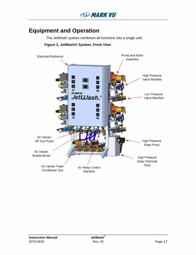
Equipment and Operation The JetWash system combines all functions into a single unit.
The JetWash® system combines all functions into a single unit.
Figure 2, JetWash® System, Front View

JetWash® Instruction Manual
Page 18 Rev. 02 6370-0630
Figure 3, JetWash® System, Back View

Instruction Manual JetWash®
6370-0630 Rev. 02 Page 19
Hot Water Inlet Manifold
The cold rinse manifold is a pressurized manifold fed directly from the soft water supply. There is a regulator on this manifold to provide consistent feed pressure to the pumps. This pressure should be set to 20-40 psi for proper operation. This water is used for all functions except Cold Water Rinse and Spot Free Rinse.
Cold Water Inlet Manifold
The cold rinse manifold is a pressurized manifold fed directly from the soft water supply. There is a regulator on this manifold to provide consistent feed pressure to the pumps. This pressure should be set to 40-60 psi for proper operation. This is used for the Cold Water Rinse function only.
Spot Free Water Inlet Manifold
The spot free rinse manifold is a pressurized manifold fed directly from the reverse osmosis unit. There is a regulator on this manifold to provide consistent feed pressure to the pumps. This pressure should be set to 40-60 psi for proper operation. This is used for the Spot Free Rinse function only.
High Pressure Pump
Each bay has an individual high pressure pump/motor assembly that is mounted on a common frame. The electrical control panels are located in an electrical enclosure on the front of the pumping plant frame. There is one electrical control panel for each pump assembly. This allows for continued operation of the system in the event that a single bay needs to be shut down for service.
The high pressure pump has an inlet manifold that provides the point of injection of high pressure soap chemical and the switching of water supplies (hot/cold/spot free). There are check valves installed to prevent reverse flow and cross contamination of water/chemical at the inlet manifold. The system, by default, gets water from the hot water manifold. When cold rinse is selected a solenoid valve opens and pressurizes the pump inlet 10-20 psi higher than the hot water forcing the pump to draw cold water. Spot free rinse operates this way also.
JetWash® Instruction Manual
Page 20 Rev. 02 6370-0630
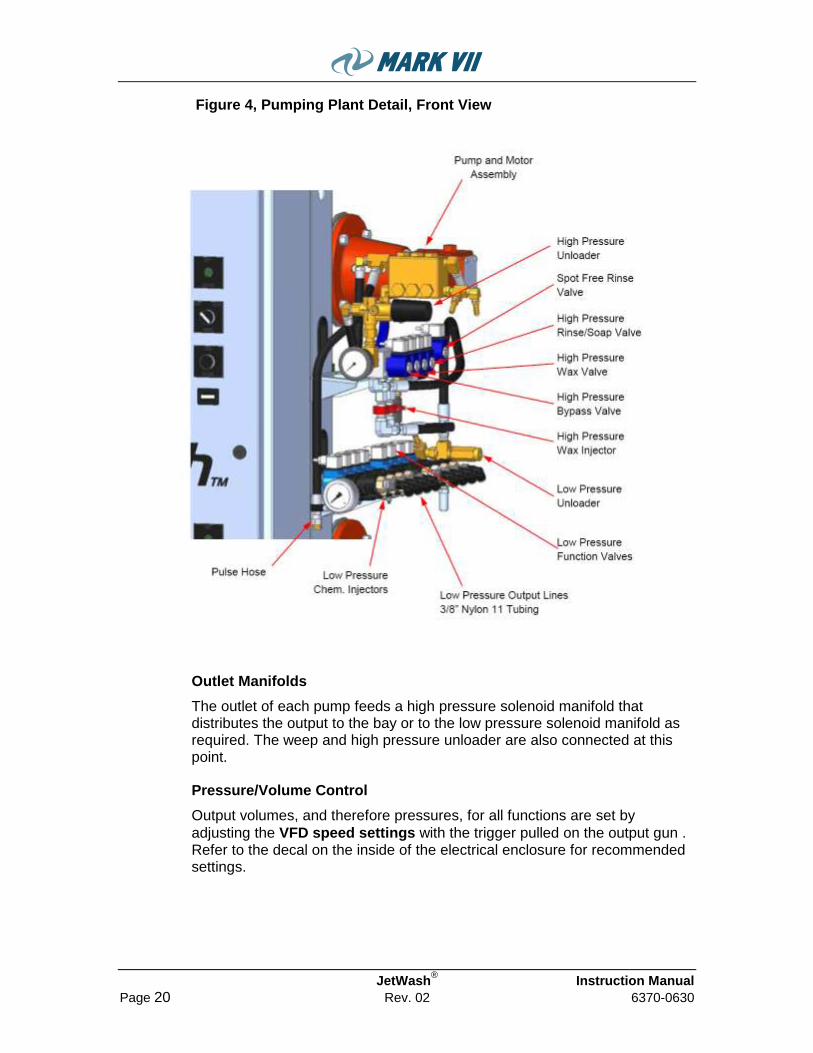
Figure 4, Pumping Plant Detail, Front View
Outlet Manifolds
The outlet of each pump feeds a high pressure solenoid manifold that distributes the output to the bay or to the low pressure solenoid manifold as required. The weep and high pressure unloader are also connected at this point.
Pressure/Volume Control
Output volumes, and therefore pressures, for all functions are set by
adjusting the VFD speed settings with the trigger pulled on the output gun . Refer to the decal on the inside of the electrical enclosure for recommended settings.

Instruction Manual JetWash®
6370-0630 Rev. 02 Page 21
Figure 5, Pumping Plant Detail, Back View
The high pressure unloader is used to control the maximum system pressure when the hp gun‟s trigger is not pulled. This should be set to 1000 psi with trigger released during a high pressure rinse cycle. The unloader itself is merely a pressure activated bypass device that allows water to be returned to the pump inlet once the desired maximum pressure is achieved. Once set, this should not require adjustment on a regular basis. If the operating pressure changes focus should be on the water flow or the nozzle restriction. These would likely be causes of pressure changes.
The low pressure unloader is used to control the maximum pressure achieved during low pressure functions such as presoak, tire cleaner, or bubble brush. This should be set to 200 psi with the trigger released during a presoak cycle.
The unit also includes two pressure relief valves installed to protect the system in the event of over pressurization. One is located on the pump head and is set at 2000 psi. The other is on the low pressure solenoid manifold and is set at 500 psi. These will discharge the water to atmosphere in the event of a dead head situation preventing equipment damage or personal harm. If these relief valves are discharging water immediate action should be taken to correct the cause and prevent further failure.

JetWash® Instruction Manual
Page 22 Rev. 02 6370-0630
The pulsing action from the pump is absorbed by a pulse hose, which connects directly to the pump. This hose provides for a smoother feeling at the trigger gun and reduces wear on other system components.
Chemical Mixing
The high pressure soap chemical is pumped into the inlet manifold by an air driven pump. Specific procedures for setting the dilution rate are in the start-up section.
The high pressure wax chemical is drawn into the pump output using a venturi injector. The dilution ratio is controlled by the injector tip. Different color tips have different size orifices which allow different flow rates of chemical to be drawn into the water flow. Refer to the chart in the appendix for approximate titration values for various tips. Flow rates through the tips, and therefore titration values, is greatly affected by the viscosity of the chemical so some trial-and-error testing will be required to find the correct tip for your specific chemical and desired ratio.
Chemical mixing for all low pressure functions (tire cleaner, presoak, bubble brush, etc.) utilizes venturi injectors similar to hp wax.
Low-Pressure Product distribution
Each of the low-pressure functions include a solenoid valve with injector (three for the tri-foam functions). When a low pressure function is selected
at the coinbox, the pump runs at low speed, the HP/LP valve on the high
pressure valve manifold opens to send the pump output to the low pressure
valve manifold and the appropriate low pressure valve opens. Water flowing through the injector draws chemical at a rate determined by the injector tip. The diluted solution is delivered to the foam generator via 3/8” Nylon 11 tubing where it is mixed with air to create foam.
Air regulators control the pressure of the injected air. Metering screws in the distribution valves control the flow rate of the foaming air.
In the event of wear or failure, each valve on the solenoid manifolds can be rebuilt without having to replace the entire manifold. Consult your Mark VII representative for rebuild kits.
Weep System
The weep system is connected to each bay at the hi-pressure manifold. There is a check valve to prevent hi-pressure reverse flow back into the weep system. For automatic weep systems there is a common N/O valve that supplies the weep system with water. This valve is controlled by a thermostat or other controller, which monitors the outside temperature and determines when weep is required. For manual weep systems, the solenoid valve is replaced with a ball valve that is controlled by the operator.
On the weep manifold there is a needle valve to control the flow rate to each bay. This should be set up at installation to approximately 32 ounces per minute as measured at the trigger gun with the trigger released. This will ensure adequate flow to prevent freezing, without wasting water. There is

Instruction Manual JetWash®
6370-0630 Rev. 02 Page 23
also a weep lock valve for each bay that is energized during low-pressure functions to prevent the weep water from diluting the specific product. This eliminates having to make set-up changes for winter operation.
Note: All solenoid valves pertaining to the weep system are N/O (normally open). This provides added safety in the event of power loss during a winter storm. If the system looses power, all bays will begin to weep in a full on cycle.
See the specific instructions for programming your weep controller that come with the controller.
Anti-Freeze Injection System
The Anti-Freeze Injection system is controlled by a dedicated control timer. The AFI controller monitors the exterior temperature (via thermostat connected at install) and the usage of the bubble brush function for each bay. When the outside temperature drops below your turn-on setting, the controller will automatically set itself for one cycle. If the bubble brush is not in use, it will wait approx. forty seconds and then begin the anti-freeze injection cycle. After the cycle is complete, the controller will wait for the bubble brush to be used for more than 20 seconds before re-arming itself.
The injection cycle runs for 20-120 seconds total. This time is adjustable with a small potentiometer inside the cover of the controller. Each injection cycle consists of four timed cycles. The first timed cycle is air only, to loosen the foam. The second injects both air and anti-freeze, to create a mixture to fill the brush. The third cycle is air only, to move the solution down to the brush. The fourth and final timed cycle is air and anti-freeze, to create a solution to protect the brush hose.
The controller then shuts down and waits for the next use. If the bubble brush function is selected during the injection cycle, the controller will immediately turn off and re-arm itself.
Electrical System
There is a common electrical enclosure that provides the electrical controls/connections for all the bays. This is the termination point for incoming power and control wiring between the equipment room components and the bay itself. On Mark VII designed equipment each bay has its own independent electrical components. The controls are all 24 VAC supplied by individual transformers. This transformer also supplies the power for the in-bay control box.
Mark VII utilizes a floating electrical system for low voltage controls. This means that all controls reference a neutral (common) connection that is generated by the transformer. None of the controls reference earth ground. This is important to know in troubleshooting so when you are checking for voltage presence, be sure to check to the common for that bay and not ground. This also provides an added safety in the event that a wiring mistake is made and high voltage is introduced to the control system component damage will not occur.

JetWash® Instruction Manual
Page 24 Rev. 02 6370-0630
Note: For safety reasons always make sure the primary power is turned off and check for voltage presence before performing repairs to the control system. Be sure to practice appropriate lock out/tag out procedures.
Bay Equipment
The JetWash® system can be used with current Mark VII Self-serve equipment. Typical components include:
High Pressure Boom for trigger gun;
Low Pressure Boom for Bubble Brush;
Foaming Conditioner applicator gun;
Coin Box for System activation
Other Equipment
Suggested list of ancillary equipment for the system:
Water Heater;
Water Softener;
R.O. Unit and Storage tank;
Air compressor;
Gas, electrical power and other public utilities.

Instruction Manual JetWash®
6370-0630 Rev. 02 Page 25
Installation Read through the instructions to determine what tools and fittings will be needed to install the equipment.
The installation of the JetWash® will focus on the Pumping Plant and some wash bay equipment. The operator should make sure that other supply system such as hot water, R/O system, air compressor, and public utility supplies, are installed.
Bay requirements
Bay floors
Be sure to slope your floors for good drainage. Your floors may include snow melting/de-icing system or floor heating system. If so, follow the manufacturer‟s installation instructions.
Drains and traps
Must be of adequate size and comply with local codes.
Utilities
Adequate utilities must be provided for the car wash equipment as well as lighting and heating. Equipment must be protected from freezing (see equipment specifications for requirements).
Underground conduits
Must be placed prior to pouring the concrete for such items as vacuums, exterior light poles, etc.
Overhead Booms
Boom mounting brackets must be provided to facilitate installation of the booms at later time. A sturdy box section of either 1-1/2” angle iron or trussing should be affixed to the roof section capable of holding 400 lbs. minimum.
Coin boxes and safe
Normally, the coin boxes are built into the wall structures. They should be located within two feet of the end of the wall for security purposes. A 1-1/4” conduit must be run from the top of the coin box to the top of the wall in order to facilitate wiring at the later time.

JetWash® Instruction Manual
Page 26 Rev. 02 6370-0630
Equipment room requirements
Equipment room
Must be large enough to accommodate all of the required car wash equipment and have space for chemical storage, plus a work area, if desired. The equipment room door should be at least 3 ft. wide.
Bill changers
Opening(s) must be provided in the equipment room wall for each bill changer. The dimensions and installation instructions for the bill changer are listed in the manufacturer‟s manual. The bottom of the opening should be 30” above the paving grade. Allow enough room for the bill changer door to open Locate an electrical outlet near the bill changer for proper operation (see electrical detail).
Utilities
Adequate utilities must be provided for the car wash equipment as well as lighting and heating. Equipment must be protected from freezing.
Venting
All appliances must be properly vented in compliance with local codes.
Drains
The water softener control valve(s) must be connected to the drain (floor or standpipe). Be sure to drain your equipment room well. A good rule of thumb is to include enough drainage to accommodate twice the water supply, without significant build up.
Note: Local codes dictate proper connections to drains. Maintain proper air gap and backflow protection.

Instruction Manual JetWash®
6370-0630 Rev. 02 Page 27
Pumping Plant Connections
Place the unit(s) in the equipment room as indicated on the layout drawings. It should be placed to minimize plumbing runs from the water softener, water heater, and reverse osmosis unit. Proper access and work spaces should be provided as needed in the front, back, and side of the unit, recommended minimum: 12”.
Figure 6, Installation Connections, Front & Top Views
JetWash® Instruction Manual
Page 28 Rev. 02 6370-0630
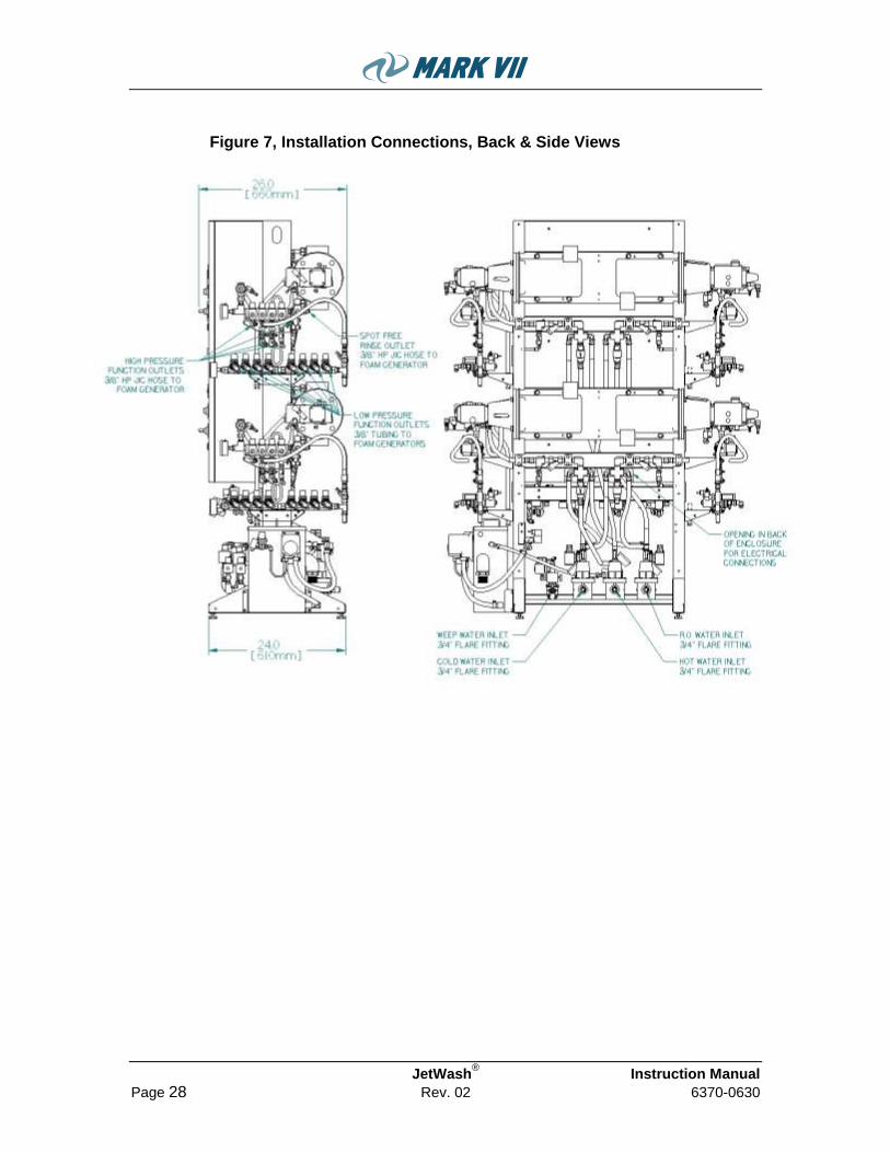
Figure 7, Installation Connections, Back & Side Views
Instruction Manual JetWash®
6370-0630 Rev. 02 Page 29
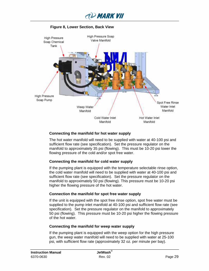
Figure 8, Lower Section, Back View
Connecting the manifold for hot water supply
The hot water manifold will need to be supplied with water at 40-100 psi and sufficient flow rate (see specification). Set the pressure regulator on the manifold to approximately 35 psi (flowing). This must be 10-20 psi lower the flowing pressure of the cold and/or spot free water.
Connecting the manifold for cold water supply
If the pumping plant is equipped with the temperature selectable rinse option, the cold water manifold will need to be supplied with water at 40-100 psi and sufficient flow rate (see specification). Set the pressure regulator on the manifold to approximately 50 psi (flowing). This pressure must be 10-20 psi higher the flowing pressure of the hot water.
Connection the manifold for spot free water supply
If the unit is equipped with the spot free rinse option, spot free water must be supplied to the pump inlet manifold at 40-100 psi and sufficient flow rate (see specification). Set the pressure regulator on the manifold to approximately 50 psi (flowing). This pressure must be 10-20 psi higher the flowing pressure of the hot water.
Connecting the manifold for weep water supply
If the pumping plant is equipped with the weep option for the high pressure gun, the weep water manifold will need to be supplied with water at 25-100 psi, with sufficient flow rate (approximately 32 oz. per minute per bay).

JetWash® Instruction Manual
Page 30 Rev. 02 6370-0630
Figure 9, Lower Section, Front View

Instruction Manual JetWash®
6370-0630 Rev. 02 Page 31
Figure 10, Electrical Enclosure
Electrical Connections
To connect the coin box to the pump station, use the 19-conductor cable (P/N 0046-0502), which is supplied in an uncut length. Run one length of cable between the coin box and each electrical panel. The wiring diagram shows which connections to make and all the necessary hardware is supplied.
Connect the appropriate incoming power to each pumping plant as per the included wiring diagram.
Inverter (VFD)
24 VAC Transformer Tri-Foam Controller
Coinbox
Connections
Power Connections
Cable Entry

JetWash® Instruction Manual
Page 32 Rev. 02 6370-0630
Connecting the low pressure output lines
The low-pressure solenoid manifold assemblies are located below the high pressure manifold. There is one manifold for each bay. Each assembly contains a block of solenoids with chemical injectors. These assemblies distribute chemical solutions to each bay.
Use the supplied tubing to run the air and chemical lines from each solenoid to the foam generator at its bay. Measure the length of each run and cut the tubing cleanly, as a tapered or ragged cut can interfere with a proper seal. Assignment of the tubing colors for the chemicals is listed in Figure 11.
Figure 11, Chemical Tubing Color assignment
Chemical Tubing Color
Tire Cleaner Green
Wheel Cleaner Black
Presoak Orange
High Pressure Soap Yellow
Bug Cleaner Purple
Triple foam, or Bubble Brush Red
Tri-Color, or foaming Conditioner Blue
Clearcoat Natural
Glass Cleaner Natural
Anti-freeze Green
Weep Green
Air Natural
Instruction Manual JetWash®
6370-0630 Rev. 02 Page 33
Installing the Wash Bay Equipment
Equipment installation
All coin boxes
A 1-1/4” conduit must be run from each wall above the coin boxes, single or double face, to each of the control panels on the JetWash® pumping plant. Low voltage wire is provided by Mark VII Equipment to run in the conduit.
All control panels
Strip the coin box cable and install each wire color for color (1 thru 12) on the vertical terminal strip. The use of crimp-on type connectors is recommended for the ease of service and neatness.

JetWash® Instruction Manual
Page 34 Rev. 02 6370-0630
360° Dual Booms
Figure 12, 360° Dual Boom
Reference drawing number 7030-2574
Step 1: Find the center of the bay, front to back and side to side. Locate the roof structure closest to this mark. The booms will be fastened to the structure, in 14” x14 “ square pattern, using ½” bolts. Refer to the illustration for placement of the double booms: Use ½” fender washers (not supplied) to shim the outside mounting holes. That is the two left side holes on one boom and the right side holes on the other. This way the booms will swing to the outside of the bay by themselves. If only one boom is used, center it in the bay.
There is some flexibility built in. If any change is made from the recommended placement, be sure to check all clearances before locking the bolts.
Step 2: Attach the hoses to either the high-pressure wand or the brush.
When installing dual booms, note the location of the in-bay coin box. The high-pressure boom should always be mounted closest to the coin box and the gun should be placed at rest within an arm‟s reach of the box. The bubble brush should be the furthest boom from the coin box and should hang at rest on the opposite corner of the bay from the high-pressure gun (see Figure 13).
14" x 14" HOLE PATTERN
1/2" SHIM1 1/4" DIA. RUBBER BUMPER(2 SUPPLIED PER BOLT)
ATTACH HOSE
1/2" SHIM
1'-8 1/4"

Instruction Manual JetWash®
6370-0630 Rev. 02 Page 35
Figure 13, Dual boom mounting
7.5"
7.5"
21"
21"
7.5"
7.5"
21"
21"
18"
18"
36"
SIDE TO SIDEMOUNTING
FRONT TO REARMOUNTING
DIRECTIONOF VEHICLES
COIN BOX
HIGH-PRESSURE
BUBBLEBRUSH

JetWash® Instruction Manual
Page 36 Rev. 02 6370-0630
180° Bubble Brush Boom
Figure 14, 180° Bubble Brush Boom
Install the boom on the wall opposite the coin box to avoid interference with the high-pressure wand. The boom should be mounted so that it swings “home” when not in use. It should also be allowed to drain out. To help with this, use the bolt pattern illustrated. It is also recommended that 3/16” spacers or washers are used at the bottom bearing.
3 7/8"
1 1/4"
12 "

Instruction Manual JetWash®
6370-0630 Rev. 02 Page 37
Installing the Foam Generator for the High Pressure Gun
Figure 15, HP Gun Foam Generator
Reference part number 7080-2202 thru 7080-2208
This illustration is an HP gun foam generator set up for four low pressure gun functions (e.g. presoak, tire cleaner, wheel cleaner, and bug buster). Manifolds will be built specific for each order according to the system requirements. There will be one assembly per bay. Each assembly is approximately 2‟ long and should be mounted as close to the high pressure boom inlet as possible to reduce change-over time.
Step 1. Measure the length of the run between the pump and the foam generator and between the foam generator and the boom inlet. Purchase
enough 3/8” high-pressure hose with female 37° JIC fittings for all high pressure lines.
Step 2. Bring the ¼” air and 3/8” foaming fluid tubing lines through the chase from the equipment room. Cut to length and push into the self-locking fittings shown. Be careful to ensure that the ends are very straight as tapered or ragged cuts can cause a failure of the seal.
Step 3. Bring the 3/8” high-pressure lines from the pump output manifold to the foam generator. Connect where shown. Use a shorter high-pressure hose to connect the foam generator to the boom inlet.

JetWash® Instruction Manual
Page 38 Rev. 02 6370-0630
Installing the Bubble Brush Foam Generator
Figure 16, Bubble Brush Foam Generator
Reference part number 7080-2212 thru 7080-2214
This illustration is of the bubble brush foam generator assembly with the antifreeze option. The generator will vary if you have air weep or no freeze protection, but you will have one generator for each brush. They are about 1‟-6” in length and should be mounted reasonably close to the brush boom inlet.
Step 1. Bring the ¼” air line(s) and 3/8” fluid lines from the low pressure solenoid manifold. Cut to length and push into the self-locking fittings as shown. As always, be careful to ensure that the ends are straight as tapered or ragged cuts can cause the seal to fail.
Step 2. Cut to length the ½” low pressure hose and attach one end to the foam generator and the other to the bubble brush boom inlet.

Instruction Manual JetWash®
6370-0630 Rev. 02 Page 39
Installing the Foam Conditioner Applicator
Figure 17, Foam Conditioner Applicator
Reference part number 7080-2200
The foam conditioner applicator can be used for single or tri-color foaming conditioner.
Step 1. Mount the restraint bracket on the wall near one end of the bay at about 8‟ to 10‟ high, using ¼” or 5/16” screws. The gun “holster” mounts approximately 3‟ above the floor and 3‟-4‟ away from the bracket.
Step 2. Cut to length the ½” low pressure hose and attach one end to the foam generator and the other to the restraint bracket fitting.
Step 3. Bring the ¼” air line(s) and 3/8” fluid lines from the low pressure solenoid manifold. Cut to length and push into the self-locking fittings as shown. As always, be careful to ensure that the ends are straight as tapered or ragged cuts can cause the seal to fail.
GUN
GUNHOLSTER
FOAM GENERATOR
FLUIDIN
AIRIN
RESTRAINTBRACKET
FLEXCOILHOSE

JetWash® Instruction Manual
Page 40 Rev. 02 6370-0630
Installing the Coin Box
Figure 18, Coin Box
Install the coin box and safe in the wall, reinforcing as necessary for security. Run the supplied cable between the coin box and the pumping station in the equipment room, which corresponds to the bay. Use the wiring diagram to finish the connections at both ends. Coin boxes with the two faces will be wired to two pumping stations. (Both are shown without doors.)
SAFE [SMALL]
10 3/4"11 1/2"
SAFE [LARGE]
11 1/2"
7 1/4"
COIN BOX [SINGLE]
15 1/2"
9"
COINBOX [DOUBLE]
10"
17 3/4"
COIN BOX
COIN SAFE
COIN BOX INSTALLATION
1-1/4" COIN DROPCONDUIT
2'(OR BY SIZE OFBLDG. UNIT)
4'-6" TYP.
1-1/4" CONTROL WIRECONDUIT
15 1/2"
15 1/2"15 1/2"
7 1/4"

Instruction Manual JetWash®
6370-0630 Rev. 02 Page 41
Start-up
A. Pump oil
The crankcases of the pumps have been filled at the factory. However, you must check the oil level of each pump to make sure that there has been no leakage.
B. Chemicals
Install the appropriate metering tip in the hose barb of each injector; refer to the chart in the appendix for approximate dilution rates. A hose with foot valve must then be run from each chemical injector into the container of their respective chemical. These containers should be checked regularly.
Install the recommended tip in the eductor of the hydrominder in the HP Soap Tank (see chemical supplier recommendation). Then, with the foot valve in the storage container, use a vacuum gun to draw the product to the eductor tee. Re-connect the chemical line to the eductor. This will ensure that the solution is as close as possible to the desired strength, which will aid setting up in the bays.
C. Water softener
Your water softener needs to be set up for the local conditions. Refer to the set-up/programming manual for specific instructions.
D. Underfloor heat start-up
Make sure your under floor heater is properly operated. Refer to manufacturer‟s instructions.
E. Water
Before turning on the water supply, ensure that all service valves are in the „off‟ position. Once the incoming water line is pressurized, open all of the water valves one at a time and check for leaks.
F. Water heater
Make sure your water heater is properly operated. Refer to manufacturer‟s instructions. Turn on the power to the water heater. Water temperature should be no more than 130°F. Output pressure must be between 40 and 100 psi.
G. Turn on power
Turn on the power at circuit breakers.
H. Coinbox Timers
Check to see that timers are set to the desired price and time before starting up. Read directions carefully before setting.

JetWash® Instruction Manual
Page 42 Rev. 02 6370-0630
I. Pump Plant Systems check
-1 Remove all trigger wands from their bay hoses.
-2 Make sure all valves at the inlet manifolds (below the pumps) are turned to full open.
-3 If a programmable coin acceptor was selected, check programming to ensure it meets customer‟s requirements. Refer to instructions for specific coin acceptor. Insert quarters in the first bay‟s coin box with the rotary switch in the „stop‟ position. The green light will turn on after the minimum numbers of coins have been inserted.
-4 Turn rotary switch to “High Pressure Rinse”, the pump should then turn on and run at high speed. If the unit has the “Temperature Selectable Rinse” option, set selector switch to “Cold” for the initial set up. At this time check the rotation of the motors. Rotation should be toward the pump head at the top of each revolution. While the pump is running, adjust the pressure of the incoming cold water to 40-60 psi. This pressure must be 10-20 psi higher than that the hot water pressure (see step 6 below).
-5 Turn the rotary switch to “Spot Free Rinse” and adjust the incoming spot free rinse water to 40-60 psi. This pressure must be 10-20 psi higher than that the hot water pressure (see step 6 below).
-6 Turn the selector switch to “soap”. Warm water will now flow to the pump. Adjust the pressure of the incoming hot water to 20-40 psi (must be 10-20 psi less than cold and spot free rinse water). After the warm water flush, turn rotary switch to “Stop” and replace the trigger wands back onto the bay hoses. Be sure the wands have the properly sized nozzles, 2507 for 3 hp or 2509 for 5 hp.
From this time on, start-up will require two persons.
-7 While holding the wand firmly, squeeze the trigger and turn the selector switch to “rinse”. The pressure will rise to the factory pre-set pressure of 1000 psi.
-8 Check the pressure reading at the gauge adjacent to the high-pressure pump. Make sure that the pressure does not exceed 1100 psi. Note: excessive pressure will cause the motor overload to trip and/or damage the equipment.
-9 Release the trigger and verify that the pressure does not exceed 1100 psi. Adjust the high pressure unloader if required to reduce the pressure to 1100 psi or less. Squeeze and release the trigger several times to ensure proper operation of the unloader valve.
-10 Soap: Set the selector switch to “High Pressure Soap”. Adjust the metering screw in the soap valve and run until desired effect is seen at the bay. Depending on the customer‟s requirements, eductor tip changes may be required.

Instruction Manual JetWash®
6370-0630 Rev. 02 Page 43
-11 Wax/Clearcoat: Set the selector switch to “High Pressure Clearcoat” position. With the trigger fully squeezed, run the function until the wax solution can be seen spraying from the nozzle. (Chemical will not be injected if the trigger is not squeezed.) The tip in the injector may need to be changed to meet the customer‟s requirements.
-12 Set the selector switch back to “High Pressure Rinse” to ensure that the chemical valves close and no further product is dispensed.
-13 Low pressure functions: Each of the low-pressure products is set up in the same manner with slight differences for the “tri-color” products. Turn on the specific product and ,with the trigger fully squeezed, run the function until the solution can be seen spraying from the nozzle. (Chemical will not be injected if the trigger is not squeezed.) The tip in the injector may need to be changed to meet the customer‟s requirements.
Release the trigger and verify that the pressure does not exceed 200 psi. Adjust the low pressure unloader if required to reduce the pressure to 200 psi. Squeeze and release the trigger several times to ensure proper operation of the unloader valve.
Use the air regulator and metering screw on the solenoid manifold to adjust the foaming air, for each bay. Once the product has been set for one function, repeat the same procedure for the remaining functions.
-14 Tri-color functions: If the system has either of the two optional tri-color functions (foam brush or conditioner), there is an additional adjustment on the timer that controls the cycling of the valves. This is done to provide a „rainbow‟ effect in the bay.
-15 Once all the products are set, and performing as desired, repeat on each additional bay.
-16 Weep: Turn on weep system and set the temperatures so that all bays are “full on” weep. Set the weep flow rate (trigger released) to approximately 32 oz/min.
-17 Bubble Brush/Foaming Conditioner Gun Air Weep: Turn the function on to get foam into the lines going to the bay, then shut the function back off. While there is still foam in the lines, turn on the weep system. Slowly adjust the needle valve for each bay by opening (clockwise) it until the foam is pushed out of the line at a rate of about 2 to 4 inches per second. Your weep system is now adjusted for the winter season.
-18 Anti-Freeze Injection start-up: The Anti-Freeze Injection System is similar to the low-pressure functions but is controlled by the Anti-Freeze timer and utilizes the same air valve as the bubble brush function. For initial start up, adjust the “turn-on”
JetWash® Instruction Manual
Page 44 Rev. 02 6370-0630
setting to be higher than the outside temperature. After the bay has been inactive for approximately 40 seconds, the timer will begin one cycle. See “Anti-Freeze Injection” section for operational details.

Instruction Manual JetWash®
6370-0630 Rev. 02 Page 45
Appendix
A. Approximate Injector Dilution Ratios and Rates Chart
Figure 19, Approximate Injector Dilution Ratios and Rates Chart