
March 2015 INDUSTRIAL BERRY · i i “industrialberry_datasheet” — 2015/3/21 — 10:25 — page...
21
CanBerry PI V 2.0 INDUSTRIAL BERRY www.industrialberry.com March 2015
Transcript of March 2015 INDUSTRIAL BERRY · i i “industrialberry_datasheet” — 2015/3/21 — 10:25 — page...

ii
“industrialberry_datasheet” — 2015/3/21 — 10:25 — page i — #3 ii
ii
ii
CanBerry PI V 2.0
INDUSTRIALBERRY
www.industrialberry.com
March 2015

ii
“industrialberry_datasheet” — 2015/3/21 — 10:25 — page iii — #5 ii
ii
ii
Contents
1 License 11.1 Disclaimer . . . . . . . . . . . . . . . . . . . . . . . . . . . . . . 1
2 Introduction 3
3 Hardware implementation 5
4 Software implementation 114.1 Real Time Clock . . . . . . . . . . . . . . . . . . . . . . . . . . 12
4.1.1 RTC with shell . . . . . . . . . . . . . . . . . . . . . . . 124.2 LED Control . . . . . . . . . . . . . . . . . . . . . . . . . . . . 13
5 Components list 15
Bibliography 17
iii

ii
“industrialberry_datasheet” — 2015/3/21 — 10:25 — page v — #7 ii
ii
ii
List of Figures
2.1 CanBerry V2.0 on Raspberry PI . . . . . . . . . . . . . . . . . 42.2 CanBerry V2.0 . . . . . . . . . . . . . . . . . . . . . . . . . . . 4
3.1 Electric diagram of CanBus block . . . . . . . . . . . . . . . . . 63.2 Electric diagram of RTC block . . . . . . . . . . . . . . . . . . 73.3 CanBerry Connector . . . . . . . . . . . . . . . . . . . . . . . . 73.4 Raspberry HAT Eeprom . . . . . . . . . . . . . . . . . . . . . . 83.5 CAN Bus example, image from http://en.wikipedia.org/wiki/
File:CAN-Bus_Elektrische_Zweidrahtleitung . . . . . . . . 83.6 CANH Bus monitoring . . . . . . . . . . . . . . . . . . . . . . . 9
v

ii
“industrialberry_datasheet” — 2015/3/21 — 10:25 — page vii — #9 ii
ii
ii
List of Tables
5.1 CanBerry Pi V 2.0 . . . . . . . . . . . . . . . . . . . . . . . . . 16
vii

ii
“industrialberry_datasheet” — 2015/3/21 — 10:25 — page 1 — #11 ii
ii
ii
Chapter 1
License
Open-source hardware shares much of the principles and approach of free andopen-source software. In particular, we believe that people should be ableto study our hardware to understand how it works, make changes to it, andshare those changes. To facilitate this, we release all of the original design files(Eagle CAD) for the IndustrialBerry hardware. These files are licensed undera Creative Commons Attribution Share-Alike license, which allows for bothpersonal and commercial derivative works, as long as they credit Industrial-Berry and release their designs under the same license. The IndustrialBerrysoftware/firmware is also open-source.
1.1 DisclaimerIn no event shall Industrialberry be liable to the buyer or to any third partyfor any indirect, incidental, special, consequential, punitive or exemplary dam-ages (including without limitation lost profits, lost savings, or loss of businessopportunity) arising out of or relating to any product or service provided or tobe provided by Industrialberry, or the use or inability to use the same, even ifIndustrialberry has been advised of the possibility of such damages.
1

ii
“industrialberry_datasheet” — 2015/3/21 — 10:25 — page 2 — #12 ii
ii
ii

ii
“industrialberry_datasheet” — 2015/3/21 — 10:25 — page 3 — #13 ii
ii
ii
Chapter 2
Introduction
CanBerry Pi V 2.0 is an extension board for RaspBerry Pi. It is an OpenHardware Design. It has two functionalities: a can bus module and an onboardReal Time clock powered by a 12 mm battery. In fig 2.1 is shown the Board onRaspberry PI B+. The CanBus is based on MCP2515 [1] SPI controller andthe MCP2551 [2] tranceiver. All functionalities are full integrated in standardlinux kernel, so, they can be avaible on fly, or at last recompiling linux kernelto add canbus functionalities. The real time clock is based on DS3231 [3](withinternal oscillator ) or DS1307Z [4] I2C controller. It is full compatible withlinux too. Using I2C Kernel module, and standard kernel functions, date andhour can be set/get by simple commands. On the bottom side is located an onboard battery to guarantee a data autonomy more than 20 years. In chapterhardware there are all informations on principal components, schematics torebuild and modify RaspBerry PI board. In chapter Software is reported howall hardware can be used: as recompile kernel, build simple user space functionto set and get I2C data, etc... In chapter application is reported a typicalexample of how to use the board.
3

ii
“industrialberry_datasheet” — 2015/3/21 — 10:25 — page 4 — #14 ii
ii
ii
Chapter 2 Introduction
Figure 2.1: CanBerry V2.0 on Raspberry PI
Figure 2.2: CanBerry V2.0
4

ii
“industrialberry_datasheet” — 2015/3/21 — 10:25 — page 5 — #15 ii
ii
ii
Chapter 3
Hardware implementation
CanBerry PI 2.0 is composed by two blocks: a CanBus Module shown in Fig.3.1 and a Real Time Clock shown in 3.2 The SMD Jumper JP2 must be usedto connect the RTC Int pin to Raspberry GPIO7.MCP2515 is a stand alone SPI canbus controller full integrated in linux
kernel. At the start, the driver was implemented as a block device. Recently itis assumed to be a network module into the kernel. It is supplied by 3.3V fromraspberry connector (fig 3.3 ). MCP2551 is supplied by 5V from Raspberryconnector insted. So, to match voltage physical level between the two chips, avoltage matching made by R3 and R4 has been used. The SMD Jumper JP3must be used for the first and the last device of CAN Bus, this jumper providesthe 120 Ω termination (see fig 3.5).
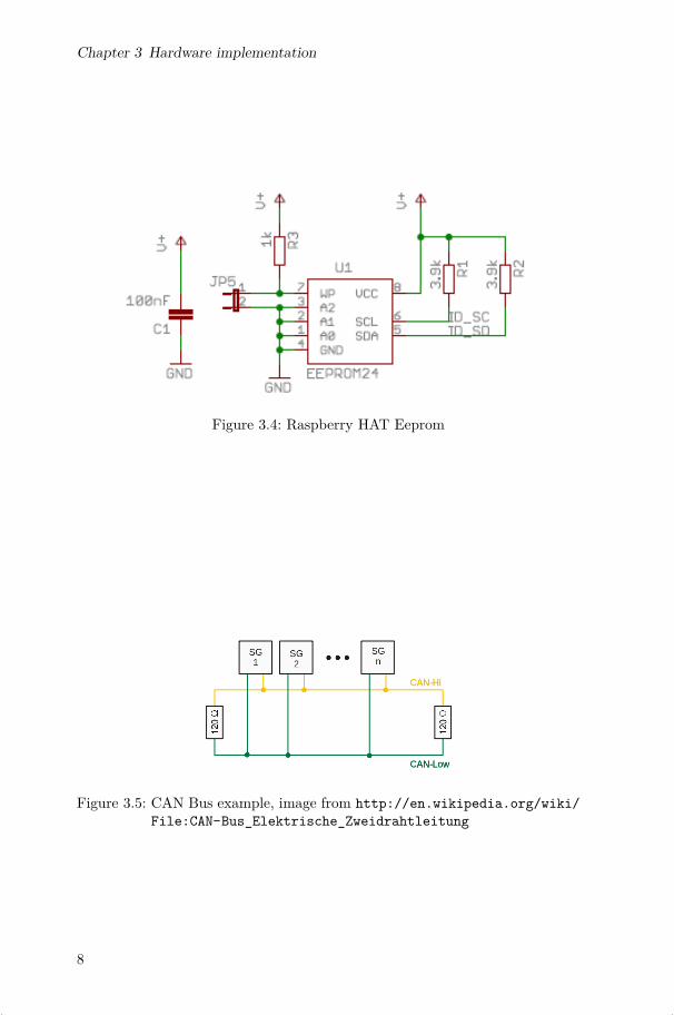
The Raspberry Pi B+ has been designed specifically with add-on boards inmind and today we are introducing HATs (Hardware Attached on Top). Asignificant feature of HATs is the inclusion of a system that allows the B+ toidentify a connected HAT and automatically configure the GPIOs and driversfor the board, making life for the end user much easier! The automatic con-figuration is achieved using 2 dedicated pins (ID SD and ID SC) on the 40WB GPIO header that are reserved for an I2C EEPROM CAT24C32WI. TheEEPROM (see fig 3.4).You can see in fig.3.6 the signal on pin CANH
5

ii
“industrialberry_datasheet” — 2015/3/21 — 10:25 — page 6 — #16 ii
ii
ii
Chapter 3 Hardware implementation
Figure 3.1: Electric diagram of CanBus block
6

ii
“industrialberry_datasheet” — 2015/3/21 — 10:25 — page 7 — #17 ii
ii
ii
Figure 3.2: Electric diagram of RTC block
Figure 3.3: CanBerry Connector
7
ii
“industrialberry_datasheet” — 2015/3/21 — 10:25 — page 8 — #18 ii
ii
ii
Chapter 3 Hardware implementation
Figure 3.4: Raspberry HAT Eeprom
Figure 3.5: CAN Bus example, image from http://en.wikipedia.org/wiki/File:CAN-Bus_Elektrische_Zweidrahtleitung
8

ii
“industrialberry_datasheet” — 2015/3/21 — 10:25 — page 9 — #19 ii
ii
ii
Figure 3.6: CANH Bus monitoring
9

ii
“industrialberry_datasheet” — 2015/3/21 — 10:25 — page 10 — #20 ii
ii
ii

ii
“industrialberry_datasheet” — 2015/3/21 — 10:25 — page 11 — #21 ii
ii
ii
Chapter 4
Software implementation
How to prepare a SD Card with CAN kernel modules
Download Wheezy raspbian 2014-09-09
After your raspberry has been booted, go to home directory:
cd /home/pi/nano can-start.sh
add these lines to the script
#!/bin/sh#Caninsmod /lib/modules/3.12.28+/kernel/drivers/spi/spi-bcm2708.koinsmod /lib/modules/3.12.28+/kernel/net/can/can.koinsmod /lib/modules/3.12.28+/kernel/drivers/net/can/can-dev.koinsmod /lib/modules/3.12.28+/kernel/net/can/can-raw.koinsmod /lib/modules/3.12.28+/kernel/net/can/can-bcm.koinsmod /lib/modules/3.12.28+/extra/spi-config.ko
devices=\bus=0:cs=0:modalias=mcp2515:speed=10000000:gpioirq=25:pd=20:pds32-0=16000000:pdu32-4=0X2002:force_releaseinsmod /lib/modules/3.12.28+/kernel/drivers/net/can/mcp251x.koip link set can0 up type can bitrate 1000000
Run the script:
sudo sh can-start.sh
So the system is ready, then you can use standard canbus command to usethe peripheral:
candump can0 -> to monitoring can bus trafficcansend can0 7DF#0201050000000000 -> to send canbus commands
11

ii
“industrialberry_datasheet” — 2015/3/21 — 10:25 — page 12 — #22 ii
ii
ii
Chapter 4 Software implementation
4.1 Real Time Clock
It is possible use the RTC IC with the terminal or with a compiled program.The DS1307Z is a device I2C, and then we must install i2c-tool
sudo aptitude install i2c-tool
and libi2c-dev before use it.
sudo aptitude install libi2c-dev
4.1.1 RTC with shell
The following code allow the management of the RTC with the i2c-tool directlyfrom the shell. Verify the DS1307Z address 0x68 with
sudo i2cdetect -y 0
for Raspberry Rev 1 or
sudo i2cdetect -y 1
for Rev 2 and B+, because the I2C bus address changed from 0 to 1.Run the scripts as root:
modpro be rtc-ds1307
Then, run
echo ds1307 0x68 > /sys/class/i2c-adapter/i2c-0/new_device (if you havea Rev 1 Pi)
echo ds1307 0x68 > /sys/class/i2c-adapter/i2c-1/new_device (if you havea Rev 2 Pi)
Set RTC with
hwclock -w
Read RTC with
hwclock -r
12

ii
“industrialberry_datasheet” — 2015/3/21 — 10:25 — page 13 — #23 ii
ii
ii
4.2 LED Control
4.2 LED Control
Go to home directory:
cd /home/pi/nano gpio_on.sh
add these lines to the script
#!/bin/sh
# Set up GPIO 27 and set to outputecho "27" > /sys/class/gpio/exportecho "out" > /sys/class/gpio/gpio27/direction
# Set up GPIO 4 and set to outputecho "4" > /sys/class/gpio/exportecho "out" > /sys/class/gpio/gpio4/direction
# Write output#Led1 Onecho "1" > /sys/class/gpio/gpio27/value#Led2 Onecho "1" > /sys/class/gpio/gpio4/value
# Clean upecho "27" > /sys/class/gpio/unexportecho "4" > /sys/class/gpio/unexport
nano gpio_off.sh
add these lines to the script
#!/bin/sh
# Set up GPIO 27 and set to outputecho "27" > /sys/class/gpio/exportecho "out" > /sys/class/gpio/gpio27/direction
# Set up GPIO 4 and set to outputecho "4" > /sys/class/gpio/exportecho "out" > /sys/class/gpio/gpio4/direction
13

ii
“industrialberry_datasheet” — 2015/3/21 — 10:25 — page 14 — #24 ii
ii
ii
Chapter 4 Software implementation
# Write output#Led1 Offecho "0" > /sys/class/gpio/gpio27/value#Led2 Offecho "0" > /sys/class/gpio/gpio4/value
# Clean upecho "27" > /sys/class/gpio/unexportecho "4" > /sys/class/gpio/unexport
Run the scripts as root:
sh gpio_on.shsh gpio_off.sh
14

ii
“industrialberry_datasheet” — 2015/3/21 — 10:25 — page 15 — #25 ii
ii
ii
Chapter 5
Components list
In the table 5.1 we can see the Bill of Material for the board, all the componentsare available on-line. For simplicity, every component has a DigiKey order code(www.digikey.com).
15

ii
“industrialberry_datasheet” — 2015/3/21 — 10:25 — page 16 — #26 ii
ii
ii
Chapter 5 Components list
Quantity
ValuePackage
PartsDigikey-cod
Unit
Price$
2Yellow
1206LED
1,LED2
754-1144-1-ND
0,210,42
1120
Ω0603
R10
RMCF0603JT
120RCT-N
D0,02
0,022
499Ω
0603R13,R
14RMCF0603FT
499RCT-N
D0,04
0,085
4.7kΩ
0603R1,R
2,R3,R
6,R7
RMCF0603JT
4K70C
T-N
D0,02
0,104
10kΩ
0603R5,R
8,R11,R
15P10K
GCT-N
D0,10
0,401
18kΩ
0603R4
P18KGCT-N
D0,10
0,102
22pf0603
C5,C
7445-1273-1-N
D0,10
0,204
100nf0603
C1,C
2,C4,C
8445-1316-1-N
D0,10
0,401
1uf0603
C9
445-1322-1-ND
0,100,10
116M
Hz
HC49/U
SQ1
535-10226-1-ND
0,410,41
1MCP2551
SOIC
8IC
1MCP2551-I/SN
-ND
1,121,12
1MCP2515
SOIC
18IC
2MCP2515-I/SO
-ND
1,981,98
1DS3231
SOIC
16IC
4DS3231S-N
D8.35
8.351
CAT
24C32W
I-GT3
SOIC
8IC
5CAT
24C32W
I-GT3C
T-N
D0.57
0.571
RETA
INER
COIN
12MM
BAT
100BAT
-HLD
-012-SMT-N
D0,27
0,271
TER
MIN
AL-3-PC
B3X
3.5mm
X1
277-8807-ND
0,370,37
1Header
40pos
2X
20SA
M1086-20-N
D3.30
3.301
PCB
3.203.20
Total21.39
Table5.1:C
anBerry
PiV2.0
16

ii
“industrialberry_datasheet” — 2015/3/21 — 10:25 — page 17 — #27 ii
ii
ii
Bibliography
[1] Microchip. MCP2515 Datasheet. http://ww1.microchip.com/downloads/en/devicedoc/21801e.pdf.
[2] Microchip. MCP2551 Datasheet. http://ww1.microchip.com/downloads/en/devicedoc/21667d.pdf.
[3] Maxim. DS3231 Datasheet. http://datasheets.maximintegrated.com/en/ds/DS3231-DS3231S.pdf.
[4] Maxim. DS1307Z Datasheet. http://datasheets.maximintegrated.com/en/ds/DS1307.pdf.
17