Manual reparacion Jeep Compass - Patriot Limited 2007-2009_Front suspension
Upload
gustavo-castroCategory
view
56download
8
2009 ENGINE
Exhaust System - Compass & Patriot
DESCRIPTION
GAS ENGINE
Fig. 1: FWD EXHAUST SYSTEMCourtesy of CHRYSLER LLC
The FWD gas engine exhaust system components consist of a catalytic converter, intermediate pipe, muffler, clamps and support isolators.
Fig. 2: AWD EXHAUST - GAS ENGINECourtesy of CHRYSLER LLC
1 - CATALYTIC CONVERTER2 - CLAMP3 - I-PIPE/MUFFLER ASSEMBLY
2009 Jeep Patriot Limited2009 ENGINE Exhaust System - Compass & Patriot
2009 Jeep Patriot Limited2009 ENGINE Exhaust System - Compass & Patriot
a
Saturday, September 08, 2012 12:58:56 PM Page 1 © 2006 Mitchell Repair Information Company, LLC.
a
Saturday, September 08, 2012 12:59:00 PM Page 1 © 2006 Mitchell Repair Information Company, LLC.

The AWD gas engine exhaust system components consist of a maniverter, under floor catalytic converter, intermediate pipe, muffler, clamps and support isolators.
DIESEL ENGINE
Fig. 3: FWD EXHAUST SYSTEM - DIESELCourtesy of CHRYSLER LLC
The basic exhaust system consists of an engine exhaust manifold, turbocharger, exhaust down pipe, exhaust pipe, exhaust heat shield(s), muffler and exhaust tailpipe.
The exhaust system uses a single muffler.
The exhaust system must be properly aligned to prevent stress, leakage and body contact. If the system contacts any body panel, it will transfer objectionable noises originating from the engine to the body.
When inspecting an exhaust system, critically inspect for cracked or loose joints, stripped screw or bolt threads, corrosion damage and worn, cracked or broken hangers. Replace all components that are badly corroded or damaged. DO NOT attempt to repair.
When replacement is required, use original equipment parts (or equivalent). This will assure proper alignment and provide acceptable exhaust noise levels.
1 - MANIVERTER2 - UNDER FLOOR CATALYTIC CONVERTER3 - CLAMP4 - I PIPE/MUFFLER ASSEMBLY
1 - CATALYTIC CONVERTER2 - CLAMP3 - I-PIPE/MUFFLER ASSEMBLY
2009 Jeep Patriot Limited2009 ENGINE Exhaust System - Compass & Patriot
a
Saturday, September 08, 2012 12:58:56 PM Page 2 © 2006 Mitchell Repair Information Company, LLC.

DIAGNOSIS AND TESTING
EXHAUST SYSTEM DIAGNOSIS
RESTRICTION TEST
Exhaust system restriction can be checked by measuring back pressure using the scan tool and PEP module pressure tester.
1. Disconnect and remove the upstream (before catalytic converter) oxygen sensor. Refer to Fuel System/Fuel Injection/SENSOR, Oxygen - Removal
CAUTION: Avoid application of rust prevention compounds or undercoating materials to exhaust system floor pan exhaust heat shields. Light overspray near the edges is permitted. Application of coating will result in excessive floor pan temperatures and objectionable fumes.
CONDITION POSSIBLE CAUSES CORRECTIONEXCESSIVE EXHAUST NOISE (UNDER HOOD)
1. Exhaust manifold cracked or broken.
1. Replace manifold.
2. Manifold to cylinder head leak.
2. Tighten manifold and/or replace gasket.
3. Exhaust flex joint to manifold leak.
3. Tighten fasteners or replace gasket.
4. Exhaust flex joint. 4. Replace catalytic converter assembly.5. Pipe and shell noise from front exhaust pipe.
5. Characteristic of single wall pipes.
EXCESSIVE EXHAUST NOISE 1. Leaks at pipe joints. 1. Tighten or replace clamps at leaking joints.
2. Burned, blown, or rusted out exhaust pipe or muffler.
2. Replace muffler or exhaust pipes.
3. Restriction in muffler or tailpipe.
3. Remove restriction, if possible or replace as necessary.
4. Catalytic converter material in muffler.
4. Replace muffler and converter assembly. Check fuel injection and ignition systems for proper operation.
WARNING: The normal operating temperature of the exhaust system is very high. Therefore, never work around or attempt to service any part of the exhaust system until it is cooled. Special care should be taken when working near the catalytic converter. The temperature of the converter rises to a high level after a short period of engine operation time.
NOTE: For Special Tool identification. See Special Tools .
2009 Jeep Patriot Limited2009 ENGINE Exhaust System - Compass & Patriot
a
Saturday, September 08, 2012 12:58:56 PM Page 3 © 2006 Mitchell Repair Information Company, LLC.

2. Install the Back Pressure Test Adaptor CH8519. 3. Connect the Pressure Transducer CH7063 to the back pressure fitting. 4. Following the PEP module instruction service information, connect all required cables to the scan tool
and PEP module. Select the available menu options on the scan tool display screen for using the digital pressure gauge function.
5. Apply the park brake and start the engine. 6. With transmission in Park or Neutral, raise engine speed to 2000 RPM. Monitor the pressure readings on
the scan tool. Back pressure should not exceed specified limit. Refer to specification in table below EXHAUST BACK PRESSURE LIMITS.
7. If pressure exceeds maximum limits, inspect exhaust system for restricted component. For further catalytic converter inspection procedures. See Inspection . Replace component(s) as necessary.
EXHAUST BACK PRESSURE LIMITS
INSPECTION
INSPECTION
Inspect the exhaust pipes, catalytic converters, muffler, and resonators for cracked joints, broken welds and corrosion damage that would result in a leaking exhaust system. Inspect the clamps, support brackets, and insulators for cracks and corrosion damage.
ADJUSTMENTS
ADJUSTMENTS
A misaligned exhaust system is usually indicated by a vibration, rattling noise, or binding of exhaust system components. These noises are sometimes hard to distinguish from other chassis noises. Inspect exhaust system for broken or loose clamps, heat shields, insulators, and brackets. Replace or tighten as necessary. It is important that exhaust system clearances and alignment be maintained.
Perform the following procedures to align the exhaust system:
1. Loosen clamps and support brackets. 2. Align the exhaust system starting at the front, working rearward. 3. Tighten all clamps and brackets once alignment and clearances are achieved.
SPECIFICATIONS
TORQUE
Exhaust Back Pressure Limit (Max)Vehicle in Park/Neutral (no load) @2000 RPM 3.45 kPa (0.5 psi)
2009 Jeep Patriot Limited2009 ENGINE Exhaust System - Compass & Patriot
a
Saturday, September 08, 2012 12:58:56 PM Page 4 © 2006 Mitchell Repair Information Company, LLC.

SPECIAL TOOLS
EXHAUST SYSTEM
Fig. 4: DRBIII® Economy Kit - CH6020ACourtesy of CHRYSLER LLC
Fig. 5: HOSE, EXHAUST BACK PRESSURE - CH8519Courtesy of CHRYSLER LLC
DESCRIPTION N.m Ft. Lbs. In. Lbs.Fastener, Band Clamps 55 40 -Fasteners, Catalytic Converter to Exhaust Manifold Flange 28 - 250Fastener, under floor catalytic converter to maniverter -AWD 33 24 -
Fasteners, Intermediate Pipe Heat Shield 3.7 - 33Fasteners, Charge Air Cooler 8 - 70Hose Clamps, Charge Air Cooler 1.7 - 15Elbow Support Bracket - - -
M8 Fasteners 28 - 250M10 Fasteners 58 44 -
Fasteners, Heat Shield 28 - 250
2009 Jeep Patriot Limited2009 ENGINE Exhaust System - Compass & Patriot
a
Saturday, September 08, 2012 12:58:56 PM Page 5 © 2006 Mitchell Repair Information Company, LLC.

Fig. 6: CABLE, TRANSDUCER, 15 PSI - CH7063Courtesy of CHRYSLER LLC
BRACKETS, SUPPORT AND ISOLATORS
REMOVAL
REMOVAL
Fig. 7: Exhaust System Isolator and BracketCourtesy of CHRYSLER LLC
1. Disconnect isolator from exhaust system component. 2. Remove screws attaching isolator bracket to underbody. 3. Remove isolator assembly.
INSTALLATION
INSTALLATION
2009 Jeep Patriot Limited2009 ENGINE Exhaust System - Compass & Patriot
a
Saturday, September 08, 2012 12:58:56 PM Page 6 © 2006 Mitchell Repair Information Company, LLC.

Fig. 8: Exhaust System Isolator and BracketCourtesy of CHRYSLER LLC
1. Position isolator bracket to underbody and install attaching screws. Tighten bracket screws to frame rail to 8.5 N.m (75 in. lbs.) and bracket screws to the rear panel to 3.7 N.m (33 in. lbs.).
2. Connect isolator to exhaust system component. 3. Start the engine and inspect for exhaust leaks. Repair exhaust leaks as necessary. 4. Check the exhaust system for contact with the body panels. Make the necessary adjustments, if needed.
CONVERTER, CATALYTIC
DESCRIPTION
DESCRIPTION
The combination exhaust manifold/catalytic converter is attached to the intermediate pipe using fasteners and a gasket for sealing.
The stainless steel catalytic converter body is designed to last the life of the vehicle. Excessive heat can result in bulging or other distortion, but excessive heat will not be the fault of the converter. If unburned fuel enters the converter, overheating may occur. If a converter is heat-damaged, correct the cause of the damage at the same
WARNING: The normal operating temperature of the exhaust system is very high. Therefore, never work around or attempt to service any part of the exhaust system until it is cooled. Special care should be taken when working near the catalytic converter. The temperature of the converter rises to a high level after a short period of engine operation time.
CAUTION: DO NOT remove spark plug wires from plugs or by any other means short out cylinders. Failure of the catalytic converter can occur due to a temperature increase caused by unburned fuel passing through the converter.
2009 Jeep Patriot Limited2009 ENGINE Exhaust System - Compass & Patriot
a
Saturday, September 08, 2012 12:58:56 PM Page 7 © 2006 Mitchell Repair Information Company, LLC.

time the converter is replaced. Also, inspect all other components of the exhaust system for heat damage.
Unleaded gasoline must be used to avoid contaminating the catalyst core.
FWD vehicles use a catalytic converter located after the exhaust manifold and before the I-Pipe/Muffler assembly.
AWD vehicles use a maniverter and an under floor catalytic converter. The under floor catalytic converter is located between the maniverter and the I-Pipe/muffler assembly.
Diesel engine vehicles use a catalytic converter located between the turbocharger and the I-Pipe/Muffler assembly.
OPERATION
OPERATION
The three-way catalytic converter simultaneously converts three exhaust emissions into harmless gases. Specifically, HC and CO emissions are converted into water (H2O) and carbon dioxide (CO2). Oxides of Nitrogen (NOx) are converted into Nitrogen (N) and Oxygen. The three-way catalyst is most efficient in converting HC, CO and NOx at the stoichiometric air fuel ratio of 14.7:1.
The oxygen content in a catalyst is important for efficient conversion of exhaust gases. When a high oxygen content (lean) air/fuel ratio is present for an extended period, oxygen content in a catalyst can reach a maximum. When a rich air/fuel ratio is present for an extended period, the oxygen content in the catalyst can become totally depleted. When this occurs, the catalyst fails to convert the gases. This is known as catalyst "punch through."
Catalyst operation is dependent on its ability to store and release the oxygen needed to complete the emissions-reducing chemical reactions. As a catalyst deteriorates, its ability to store oxygen is reduced. Since the catalyst's ability to store oxygen is somewhat related to proper operation, oxygen storage can be used as an indicator of catalyst performance. Refer to the appropriate ELECTRICAL DIAGNOSTICS for diagnosis of a catalyst related Diagnostic Trouble Code (DTC).
The combustion reaction caused by the catalyst releases additional heat in the exhaust system, causing temperature increases in the area of the reactor under severe operating conditions. Such conditions can exist when the engine misfires or otherwise does not operate at peak efficiency. Do not remove spark plug wires from plugs or by any other means short out cylinders. Failure of the catalytic converter can occur due to temperature increases caused by unburned fuel passing through the converter. This deterioration of the catalyst core can result in excessively high emission levels, noise complaints, and exhaust restrictions.
Unleaded gasoline must be used to avoid ruining the catalyst core. Do not allow engine to operate above 1200 RPM in neutral for extended periods over 5 minutes. This condition may result in excessive exhaust system/floor pan temperatures because of no air movement under the vehicle.
The flex joint allows flexing as the engine moves, preventing breakage that could occur from the back-and-forth motion of a transverse mounted engine.
2009 Jeep Patriot Limited2009 ENGINE Exhaust System - Compass & Patriot
a
Saturday, September 08, 2012 12:58:56 PM Page 8 © 2006 Mitchell Repair Information Company, LLC.

REMOVAL
UNDER FLOOR CATALYTIC CONVERTER - 2.4L AWD
Fig. 9: UNDER FLOOR CATALYTIC CONVERTERCourtesy of CHRYSLER LLC
1. Raise vehicle on hoist and apply penetrating oil to band clamp fastener of component being removed.
CAUTION: Due to exterior physical similarities of some catalytic converters with pipe assemblies, extreme care should be taken with replacement parts. There are internal converter differences required in some parts of the country (particularly vehicles built for States with strict emission requirements) and between model years.
1 - COMBINATION MANIFOLD/CATALYTIC CONVERTER2 - SPHERICAL GASKET3 - BOLT AND SPRING3 - UNDER FLOOR CATALYTIC CONVERTER
WARNING: The normal operating temperature of the exhaust system is very high. Therefore, never work around or attempt to service any part of the exhaust system until it is cooled. Special care should be taken when working near the catalytic converter. The temperature of the converter rises to a high level after a short period of engine operating time.
NOTE: Do not use petroleum-based lubricants when removing/installing muffler or exhaust pipe isolators as it may compromise the life of the part. A
2009 Jeep Patriot Limited2009 ENGINE Exhaust System - Compass & Patriot
a
Saturday, September 08, 2012 12:58:56 PM Page 9 © 2006 Mitchell Repair Information Company, LLC.

2. Remove I-Pipe/Muffler assembly. See Removal. 3. Disconnect oxygen sensor electrical connectors.
4. Remove flange bolts (3), springs and spherical gasket. 5. Remove under floor catalytic converter (4) from maniverter or catalytic converter assembly (1). 6. Clean ends of pipes to assure mating of all parts. Discard broken or worn isolators, rusted or overused
clamps, supports, and attaching parts.
FWD
Fig. 10: Converter to Exhaust Manifold Connection - 2.4LCourtesy of CHRYSLER LLC
suitable substitute is a mixture of liquid dish soap and water.
NOTE: If spherical gasket is to be reused, mark orientation.
NOTE: When replacement is required on any component of the exhaust system, you must use original equipment parts (or their equivalent).
1 - GASKET2 - CATALYTIC CONVERTER3 - NUT
WARNING: The normal operating temperature of the exhaust system is very high. Therefore, never attempt to service any part of the exhaust system until it is cooled. Special care should be taken when working near the catalytic converter. The temperature of the converter rises to a high level after a
2009 Jeep Patriot Limited2009 ENGINE Exhaust System - Compass & Patriot
a
Saturday, September 08, 2012 12:58:56 PM Page 10 © 2006 Mitchell Repair Information Company, LLC.
1. Loosen intermediate pipe-to catalytic converter clamp.
2. Remove catalytic converter to exhaust manifold mounting nuts and gasket Discard gasket. 3. Remove I-Pipe/Muffler assembly insulators as necessary to slide catalytic converter out of I-Pipe/Muffler.
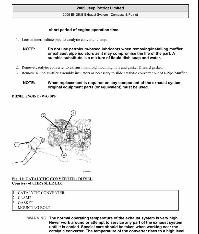
DIESEL ENGINE - W/O DPF
Fig. 11: CATALYTIC CONVERTER - DIESELCourtesy of CHRYSLER LLC
short period of engine operation time.
NOTE: Do not use petroleum-based lubricants when removing/installing muffler or exhaust pipe isolators as it may compromise the life of the part. A suitable substitute is a mixture of liquid dish soap and water.
NOTE: When replacement is required on any component of the exhaust system, original equipment parts (or equivalent) must be used.
1 - CATALYTIC CONVERTER2 - CLAMP3 - GASKET4 - MOUNTING BOLT
WARNING: The normal operating temperature of the exhaust system is very high. Never work around or attempt to service any part of the exhaust system until it is cooled. Special care should be taken when working near the catalytic converter. The temperature of the converter rises to a high level
2009 Jeep Patriot Limited2009 ENGINE Exhaust System - Compass & Patriot
a
Saturday, September 08, 2012 12:58:56 PM Page 11 © 2006 Mitchell Repair Information Company, LLC.

1. Remove the front suspension crossmember. Refer to Frame and Bumpers/Frame/CROSSMEMBER -Removal
2. Remove the intermediate pipe and muffler. See Removal . 3. Remove the catalytic converter mounting bolt (4). 4. Remove the clamp (2) and gasket (3) from the catalytic converter (1). 5. Remove the catalytic converter (1) from the vehicle.
DIESEL ENGINE - WITH DPF
Fig. 12: Catalytic Converter & Mounting Nuts And GasketCourtesy of CHRYSLER LLC
1. Loosen intermediate pipe-to catalytic converter clamp.
after a short period of engine operation time.
NOTE: Do not use petroleum-based lubricants when removing/installing muffler or exhaust pipe isolators as it may compromise the life of the part. A suitable substitute is a mixture of liquid dish soap and water.
NOTE: When replacement is required on any component of the exhaust system, original equipment parts (or equivalent) must be used.
WARNING: The normal operating temperature of the exhaust system is very high. Therefore, never attempt to service any part of the exhaust system until it is cooled. Special care should be taken when working near the catalytic converter. The temperature of the converter rises to a high level after a short period of engine operation time.
2009 Jeep Patriot Limited2009 ENGINE Exhaust System - Compass & Patriot
a
Saturday, September 08, 2012 12:58:56 PM Page 12 © 2006 Mitchell Repair Information Company, LLC.

2. Remove catalytic converter to diesel particulate filter (DPF) mounting nuts (4) and gasket (2). Discard gasket (2).
3. Remove I-Pipe/Muffler assembly insulators as necessary to slide catalytic converter out of I-Pipe/Muffler assembly.
INSPECTION
INSPECTION
Check catalytic converter for a flow restriction. See Diagnosis and Testing Exhaust System Restriction Check for procedure.
Visually inspect the catalytic converter element by using a borescope or equivalent. Remove oxygen sensor(s) and insert borescope. If borescope is not available, remove converter and inspect element using a flashlight. Inspect element for cracked or melted substrate.
INSTALLATION
UNDER FLOOR CATALYTIC CONVERTER
NOTE: Do not use petroleum-based lubricants when removing/installing muffler or exhaust pipe isolators as it may compromise the life of the part. A suitable substitute is a mixture of liquid dish soap and water.
NOTE: When replacement is required on any component of the exhaust system, original equipment parts (or equivalent) must be used.
WARNING: The normal operating temperature of the exhaust system is very high. Therefore, never attempt to service any part of the exhaust system until it is cooled. Special care should be taken when working near the catalytic converter. The temperature of the converter rises to a high level after a short period of engine operation time.
NOTE: Before replacing a catalytic converter, determine the root cause of failure. Most catalytic converter failures are caused by air, fuel or ignition problems. (Refer to Appropriate Diagnostic Information) for test procedures.
2009 Jeep Patriot Limited2009 ENGINE Exhaust System - Compass & Patriot
a
Saturday, September 08, 2012 12:58:56 PM Page 13 © 2006 Mitchell Repair Information Company, LLC.

Fig. 13: UNDER FLOOR CATALYTIC CONVERTERCourtesy of CHRYSLER LLC
When assembling exhaust system do not tighten clamps until components are aligned and clearances are checked.
1. Install under floor catalytic converter and the isolator supports to the underbody. 2. Position spherical gasket (2) with white side facing rear of vehicle, install springs, and bolts (3). Tighten
bolts to 33 N.m (24 ft. lbs.). 3. Install I-Pipe/muffler assembly. See Installation4. Working from the front of system; align each component to maintain position and proper clearance with
underbody parts. 5. Tighten band clamps to 55 N.m (40 ft. lbs.).
6. Start the engine and inspect for exhaust leaks. Repair exhaust leaks as necessary.
1 - COMBINATION MANIFOLD/CATALYTIC CONVERTER2 - SPHERICAL GASKET3 - BOLT AND SPRING3 - UNDER FLOOR CATALYTIC CONVERTER
CAUTION: Band clamps should never be tightened such that the two sides of the clamps are bottomed out against the center hourglass shaped center block. Once this occurs, the clamp band has been stretched and has lost its clamping force and must be replaced.
NOTE: Maintain proper clamp orientation when replacing with new clamp.
2009 Jeep Patriot Limited2009 ENGINE Exhaust System - Compass & Patriot
a
Saturday, September 08, 2012 12:58:56 PM Page 14 © 2006 Mitchell Repair Information Company, LLC.

7. Check the exhaust system for contact with the body panels. Make the necessary adjustments, if needed.
FWD
Fig. 14: Converter to Exhaust Manifold Connection - 2.4LCourtesy of CHRYSLER LLC
1. Position catalytic converter into I-Pipe/muffler assembly. 2. Using new gasket, position catalytic converter against exhaust manifold. 3. Install flange nuts. Tighten to 29 N.m (21 ft. lbs.). 4. Working from the front of system; align each component to maintain position and proper clearance with
underbody parts. 5. Tighten band clamps to 55 N.m (40 ft. lbs.).
6. Start the engine and inspect for exhaust leaks. Repair exhaust leaks as necessary. 7. Check the exhaust system for contact with the body panels. Make the necessary adjustments, if needed.
DIESEL ENGINE - W/O DPF
1 - GASKET2 - CATALYTIC CONVERTER3 - NUT
CAUTION: Band clamps should never be tightened such that the two sides of the clamps are bottomed out against the center hourglass shaped center block. Once this occurs, the clamp has lost clamping force and must be replaced.
2009 Jeep Patriot Limited2009 ENGINE Exhaust System - Compass & Patriot
a
Saturday, September 08, 2012 12:58:56 PM Page 15 © 2006 Mitchell Repair Information Company, LLC.

Fig. 15: CATALYTIC CONVERTER - DIESELCourtesy of CHRYSLER LLC
1. Position catalytic converter (1) into the vehicle. 2. Install the gasket (3) and clamp (2). Hand tighten the clamp (2). 3. Install the catalytic converter mounting bolt (4). 4. Install the intermediate pipe. See Installation . 5. Working from the front of system; align each component to maintain position and proper clearance with
underbody parts. 6. Tighten the clamp (2) to 7 N.m (62 in. lbs.). 7. Tighten the catalytic converter mounting bolt (4) to 28 N.m (21 ft. lbs.). 8. Install the front suspension crossmember. Refer to Frame and Bumpers/Frame/CROSSMEMBER -
Installation9. Start the engine and inspect for exhaust leaks. Repair exhaust leaks as necessary.
10. Check the exhaust system for contact with the body panels. Make the necessary adjustments, if needed.
DIESEL ENGINE - WITH DPF
1 - CATALYTIC CONVERTER2 - CLAMP3 - GASKET4 - MOUNTING BOLT
NOTE: Do not use petroleum-based lubricants when removing/installing muffler or exhaust pipe isolators as it may compromise the life of the part. A suitable substitute is a mixture of liquid dish soap and water.
2009 Jeep Patriot Limited2009 ENGINE Exhaust System - Compass & Patriot
a
Saturday, September 08, 2012 12:58:56 PM Page 16 © 2006 Mitchell Repair Information Company, LLC.

Fig. 16: Catalytic Converter & Mounting Nuts And GasketCourtesy of CHRYSLER LLC
1. Position catalytic converter into I-Pipe/muffler assembly. 2. Using a new gasket (2), position the catalytic converter (1) against the diesel particulate filter (DPF) (3). 3. Install the flange nuts (4).
Tighten to 29 N.m (21 ft. lbs.).
4. Working from the front of system; align each component to maintain position and proper clearance with underbody parts.
5. Tighten the I-Pipe/muffler assembly band clamps to 55 N.m (40 ft. lbs.).
6. Start the engine and inspect for exhaust leaks. Repair exhaust leaks as necessary. 7. Check the exhaust system for contact with the body panels. Make the necessary adjustments, if needed.
FILTER, DIESEL PARTICULATE (DPF)
DESCRIPTION
DESCRIPTION
A Diesel Particulate Filter (DPF) is installed for exhaust gas after-treatment. The DPF is located downstream of the main oxidation catalyst. The DPF filters, stores and burns particulate matter (soot) that is generated during the combustion process. The soot is oxidized to carbon dioxide CO2 at exhaust temperatures over 600° C
CAUTION: Band clamps should never be tightened such that the two sides of the clamps are bottomed out against the center hourglass shaped center block. Once this occurs, the clamp has lost clamping force and must be replaced.
2009 Jeep Patriot Limited2009 ENGINE Exhaust System - Compass & Patriot
a
Saturday, September 08, 2012 12:58:56 PM Page 17 © 2006 Mitchell Repair Information Company, LLC.

(1,112° F).
OPERATION
OPERATION
The oxidation catalysts raise the exhaust gas temperatures to regenerate the DPF , which is passive regeneration. If the passive regeneration cannot keep up with the build up of soot in the DPF, the ECM will actively regenerate the DPF to burn off the soot. Residue remains inside the DPF in the form of non burnable ash. Ash comes from the oils and other materials that are trapped in the oils and are present in the soot. Ash is not eliminated by the regeneration cycle. Excessive ash accumulation requires the replacement of the DPF. The DPF uses a silicon carbide wall-flow monolith with a platinum coating to trap particulates. The monolith contains a large number of square parallel channels, which run in the axial direction and are separated by thin porous walls. The channels are alternatively open at one end, but plugged at the other. The exhaust gases flow through the walls and escape through the pores in the wall material. Particulates, however, are too large to escape and are trapped in the monolith walls. The ECM starts the regeneration of the DPF if the soot load exceeds a performance map value. The ECM determines the load condition of the DPF based upon the exhaust gas pressure upstream and downstream of the DPF. A pressure differential sensor provides the pressure input to the ECM. During the regeneration process, the ECM raises the temperature in the DPF to burn off the soot accumulated. Under normal operation, the engine does not produce enough heat to oxidize the soot inside the DPF. This process requires temperatures above 550 °C (1,022 °F). After regeneration, the ECM reads the actual pressure difference at the DPF and compares it with a reference value. From this comparison, the ECM determines the ash quantity inside the DPF.
REMOVAL
DIESEL PARTICULATE FILTER
Fig. 17: PRESSURE DIFFERENTIAL SENSOR - 2.0L DIESELCourtesy of CHRYSLER LLC
2009 Jeep Patriot Limited2009 ENGINE Exhaust System - Compass & Patriot
a
Saturday, September 08, 2012 12:58:56 PM Page 18 © 2006 Mitchell Repair Information Company, LLC.

1. Disconnect negative battery cable. 2. Remove the engine cover. Refer to Engine - Removal3. Remove the air box assembly. Refer to Engine/Air Intake System/BODY, Air Cleaner - Removal4. Remove the right side rear engine harness bracket. 5. Remove the DPF heat shield. 6. Disconnect the temperature sensor electrical connectors. 7. Remove the temperature sensors from DPF (5). 8. Disconnect the oxygen sensor electrical connector. 9. Remove the oxygen sensor from top of DPF (5).
10. Remove the pressure differential tubing (4) from top of DPF (5). 11. Remove the DPF (5) to turbocharger clamp.
Fig. 18: DIESAL PARTICULATE FILTER TO EXHAUST PIPE FLANGECourtesy of CHRYSLER LLC
12. Raise and support the vehicle.
1 - ELECTRICAL CONNECTOR2 - PRESSURE DIFFERENTIAL SENSOR3 - MOUNTING BOLT4 - UPSTREAM PRESSURE TUBE5 - DPF6 - DOWNSTREAM PRESSURE TUBE7 - TUBING
1 - FLANGE2 - BOLT
2009 Jeep Patriot Limited2009 ENGINE Exhaust System - Compass & Patriot
a
Saturday, September 08, 2012 12:58:56 PM Page 19 © 2006 Mitchell Repair Information Company, LLC.

13. Remove the lower engine splash shield. 14. Remove the exhaust pipe to DPF mounting bolts (2). 15. Remove the exhaust pipe from the muffler and tailpipe assembly.
Fig. 19: DIESAL PARTICULATE FILTER TO AXLE BRACKET BOLTSCourtesy of CHRYSLER LLC
16. Remove the lower pressure differential tubing from the DPF. 17. Remove the exhaust manifold temperature sensor. 18. Remove the DPF (1) to axle support bracket bolts (3) 19. Remove the air charge hose at the turbo. 20. Remove the air charge hose at the engine. 21. Remove the front crossmember. Refer to Frame and Bumpers/Frame/CROSSMEMBER - Removal22. Remove the rear engine mount. Refer to Engine/Engine Mounting/INSULATOR, Engine Mount -
Removal23. Remove DPF (1) and DPF to turbocharger gasket from vehicle. Discard gasket.
INSTALLATION
DIESEL PARTICULATE FILTER
1 - DPF2 - AXLE SUPPORT BRACKET3 - DPF TO AXLE SUPPORT BRACKET BOLTS
2009 Jeep Patriot Limited2009 ENGINE Exhaust System - Compass & Patriot
a
Saturday, September 08, 2012 12:58:56 PM Page 20 © 2006 Mitchell Repair Information Company, LLC.

Fig. 20: DIESAL PARTICULATE FILTER TO AXLE BRACKET BOLTSCourtesy of CHRYSLER LLC
1. Position the DPF (1) and turbocharger gasket into the vehicle. Do not tighten at this time 2. Install the rear engine mount. Refer to Engine/Engine Mounting/INSULATOR, Engine Mount -
Installation3. Install the front crossmember. Refer to Frame and Bumpers/Frame/CROSSMEMBER - Installation4. Install the air charge hose at the engine. 5. Install the air charge hose at the turbo. 6. Install the DPF to the axle support bolts (3). Tighten the bolts to 25 N.m (18 ft. lbs.). 7. Install the exhaust manifold temperature sensor. 8. Install the lower pressure differential tubing into DPF. Tighten the fitting to 45 N.m (33 ft.lbs.)
1 - DPF2 - AXLE SUPPORT BRACKET3 - DPF TO AXLE SUPPORT BRACKET BOLTS
2009 Jeep Patriot Limited2009 ENGINE Exhaust System - Compass & Patriot
a
Saturday, September 08, 2012 12:58:56 PM Page 21 © 2006 Mitchell Repair Information Company, LLC.

Fig. 21: DIESAL PARTICULATE FILTER TO EXHAUST PIPE FLANGECourtesy of CHRYSLER LLC
9. Install the exhaust pipe to the DPF. Tighten the bolts (2) to 35 N.m (25 ft. lbs.). 10. Install the exhaust pipe to the muffler and tailpipe assembly. Tighten the bolts (2) to 35 N.m (25 ft. lbs.). 11. Install the lower engine splash shield. 12. Lower the vehicle.
Fig. 22: PRESSURE DIFFERENTIAL SENSOR - 2.0L DIESELCourtesy of CHRYSLER LLC
1 - FLANGE2 - BOLT
2009 Jeep Patriot Limited2009 ENGINE Exhaust System - Compass & Patriot
a
Saturday, September 08, 2012 12:58:56 PM Page 22 © 2006 Mitchell Repair Information Company, LLC.

13. Using a new gasket, install the DPF (5) , gasket and clamp to the turbocharger. Tighten the clamp nut to 35 N.m (25 ft. lbs.).
14. Install the oxygen sensor into the top of the DPF (5). Tighten to 45 N.m (33 ft. lbs.). 15. Connect the oxygen sensor electrical connector. 16. Install the temperature sensors to the DPF. Tighten the sensors to 45 N.m (33 ft.lbs.). 17. Connect the temperature sensor electrical connectors. 18. Install the upper pressure differential tubing (4) into the DPF (5). Tighten the tubing to 45 N.m (33
ft.lbs.). 19. Install the DPF heat shield. 20. Install the right side rear engine harness bracket. 21. Install the air box assembly. Refer to Engine/Air Intake System/BODY, Air Cleaner - Installation22. Install engine cover. Refer to Engine - Installation23. Connect the negative battery cable. 24. Start vehicle and check for leaks. Repair as necessary.
MUFFLER, EXHAUST
REMOVAL
REMOVAL
1 - ELECTRICAL CONNECTOR2 - PRESSURE DIFFERENTIAL SENSOR3 - MOUNTING BOLT4 - UPSTREAM PRESSURE TUBE5 - DPF6 - DOWNSTREAM PRESSURE TUBE7 - TUBING
2009 Jeep Patriot Limited2009 ENGINE Exhaust System - Compass & Patriot
a
Saturday, September 08, 2012 12:58:56 PM Page 23 © 2006 Mitchell Repair Information Company, LLC.

Fig. 23: MUFFLER ASSEMBLYCourtesy of CHRYSLER LLC
1. Raise vehicle on hoist and apply penetrating oil to band clamp nut and bolt of component being removed.
2. Remove exhaust system ground strap (1) at rear of I-Pipe/Muffler assembly (2). 3. Loosen band clamp and remove support isolators (3) at I-Pipe/Muffler assembly (2). Remove I-
Pipe/Muffler assembly (2) from catalytic converter. 4. Clean ends of pipes and muffler to assure mating of all parts. Discard broken or worn isolators, rusted or
overused clamps, supports, and attaching parts.
INSTALLATION
1 - GROUND STRAP2 - I-PIPE/MUFFLER ASSEMBLY3 - ISOLATOR
WARNING: The normal operating temperature of the exhaust system is very high. Therefore, never work around or attempt to service any part of the exhaust system until it is cooled. Special care should be taken when working near the catalytic converter. The temperature of the converter rises to a high level after a short period of engine operating time.
NOTE: When replacement is required on any component of the exhaust system, you must use original equipment parts (or their equivalent).
NOTE: Do not use petroleum-based lubricants when removing/installing muffler or exhaust pipe isolators (3) as it may compromise the life of the part. A suitable substitute is a mixture of liquid dish soap and water.
2009 Jeep Patriot Limited2009 ENGINE Exhaust System - Compass & Patriot
a
Saturday, September 08, 2012 12:58:56 PM Page 24 © 2006 Mitchell Repair Information Company, LLC.

INSTALLATION
Fig. 24: MUFFLER ASSEMBLYCourtesy of CHRYSLER LLC
When assembling exhaust system do not tighten clamp until components are aligned and clearances are checked.
1. Install the I-Pipe/Muffler assembly to catalytic converter and the isolator supports to the underbody. 2. Working from the front of system; align each component to maintain position and proper clearance with
underbody parts. Tighten band clamp to 55 N.m (40 ft. lbs.).
3. Connect the exhaust system ground strap. 4. Start the engine and inspect for exhaust leaks. Repair exhaust leaks as necessary.
1 - GROUND STRAP2 - I-PIPE/MUFFLER ASSEMBLY3 - ISOLATOR
CAUTION: Band clamps should never be tightened such that the two sides of the clamps are bottomed out against the center hourglass shaped center block. Once this occurs, the clamp band has been stretched and has lost its clamping force and must be replaced.
To replace the band clamp; remove the nut and peel back the ends of the clamp until spot weld breaks. File or grind remaining weld material until pipe surface is smooth.
NOTE: Maintain proper clamp orientation when replacing with new clamp.
2009 Jeep Patriot Limited2009 ENGINE Exhaust System - Compass & Patriot
a
Saturday, September 08, 2012 12:58:56 PM Page 25 © 2006 Mitchell Repair Information Company, LLC.

5. Check the exhaust system for contact with the body panels. Make the necessary adjustments, if needed.
SENSOR, EXHAUST PRESSURE
REMOVAL
EXHAUST PRESSURE SENSOR
Fig. 25: PRESSURE DIFFERENTIAL SENSOR - 2.0L DIESELCourtesy of CHRYSLER LLC
1. Disconnect and isolate negative battery cable. 2. Remove electrical connector at pressure differential sensor (2). 3. Remove upstream exhaust pressure tube (4) from catalytic converter 4. Remove downstream pressure tube (6) from catalytic converter. 5. Remove pressure differential sensor mounting bolt. 6. Remove pressure differential sensor (2) and tubing (7) from vehicle. 7. Remove tubing (7) from pressure differential sensor (2).
1 - ELECTRICAL CONNECTOR2 - PRESSURE DIFFERENTIAL SENSOR3 - MOUNTING BOLT4 - UPSTREAM PRESSURE TUBE5 - DPF6 - DOWNSTREAM PRESSURE TUBE7 - TUBING
2009 Jeep Patriot Limited2009 ENGINE Exhaust System - Compass & Patriot
a
Saturday, September 08, 2012 12:58:56 PM Page 26 © 2006 Mitchell Repair Information Company, LLC.

INSTALLATION
EXHAUST PRESSURE SENSOR
Fig. 26: PRESSURE DIFFERENTIAL SENSOR - 2.0L DIESELCourtesy of CHRYSLER LLC
1. Install tubing (7) on pressure differential sensor (2). 2. Position pressure differential sensor (2) and tubing (7). 3. Install pressure differential sensor mounting bolt (3). Tighten to 10 N.m (89 in. lbs.). 4. Install downstream pressure tube (6) into catalytic converter. Tighten the fitting to 10 N.m (89 in. lbs.). 5. Install upstream pressure tube (4) into catalytic converter. Tighten the fitting to 10 N.m (89 in. lbs.) 6. Position electrical connector (1) into bracket. 7. Connect negative battery cable.
SENSOR, EXHAUST TEMPERATURE
REMOVAL
1 - ELECTRICAL CONNECTOR2 - PRESSURE DIFFERENTIAL SENSOR3 - MOUNTING BOLT4 - UPSTREAM PRESSURE TUBE5 - DPF6 - DOWNSTREAM PRESSURE TUBE7 - TUBING
2009 Jeep Patriot Limited2009 ENGINE Exhaust System - Compass & Patriot
a
Saturday, September 08, 2012 12:58:56 PM Page 27 © 2006 Mitchell Repair Information Company, LLC.

REMOVAL
Fig. 27: Exhaust Temperature Sensor - Dpf Exhaust Temperature Sensor - Diesal Particulate FilterCourtesy of CHRYSLER LLC
1. Remove engine cover. 2. Disconnect and isolate negative batter cable. 3. Disconnect upstream DPF temperature sensor electrical connector. 4. Remove upstream DPF temperature sensor. 5. Disconnect downstream DPF temperature sensor electrical connector. 6. Remove downstream DPF temperature sensor.
INSTALLATION
INSTALLATION
1 - Upstream DPF Temperature Sensor Electrical Connector2 - Upstream DPF Temperature Sensor3 - Downstream DPF Temperature Sensor4 - Downstream DPF Temperature Sensor Electrical Connector
2009 Jeep Patriot Limited2009 ENGINE Exhaust System - Compass & Patriot
a
Saturday, September 08, 2012 12:58:56 PM Page 28 © 2006 Mitchell Repair Information Company, LLC.

Fig. 28: Diesal Particulate Filter Exhaust Temperature SensorCourtesy of CHRYSLER LLC
1. Position DPF downstream temperature sensor into DPF. Tighten to 25 N.m (221 in. lbs.). 2. Connect downstream temperature sensor electrical connector. 3. Position DPF upstream temperature sensor into DPF. Tighten to 25 N.m (221 in. lbs.). 4. Connect upstream temperature sensor electrical connector. 5. Install engine cover.
SHIELD, HEAT
DESCRIPTION
DESCRIPTION
1 - Upstream DPF Temperature Sensor Electrical Connector2 - Upstream DPF Temperature Sensor3 - Downstream DPF Temperature Sensor4 - Downstream DPF Temperature Sensor Electrical Connector
2009 Jeep Patriot Limited2009 ENGINE Exhaust System - Compass & Patriot
a
Saturday, September 08, 2012 12:58:56 PM Page 29 © 2006 Mitchell Repair Information Company, LLC.

Fig. 29: Heat ShieldCourtesy of CHRYSLER LLC
Heat shields (1), are needed to protect both the vehicle and the environment from the high temperatures developed in the vicinity of the catalytic converter.
REMOVAL
REMOVAL
1. Raise vehicle on hoist. 2. Remove fasteners attaching heat shield. 3. Remove heat shield(s)
INSTALLATION
INSTALLATION
1 - HEAT SHIELD2 - NUT3 - NUT
CAUTION: Avoid application of rust prevention compounds or undercoating materials to exhaust system floor pan heat shield. Light over-spray near the edges is permitted. Application of coating will greatly reduce the efficiency of the heat shields resulting in excessive floor pan temperatures and objectionable fumes.
2009 Jeep Patriot Limited2009 ENGINE Exhaust System - Compass & Patriot
a
Saturday, September 08, 2012 12:58:56 PM Page 30 © 2006 Mitchell Repair Information Company, LLC.

Fig. 30: Heat ShieldCourtesy of CHRYSLER LLC
1. Position heat shield(s) to underbody. 2. Install heat shield fasteners. 3. Inspect heat shield to exhaust system clearances and adjust as necessary. 4. Lower vehicle. 5. Start the engine and inspect for exhaust leaks. Repair exhaust leaks as necessary. 6. Check the exhaust system for contact with the body panels. Make the necessary adjustments, if needed.
1 - HEAT SHIELD2 - NUT3 - NUT
2009 Jeep Patriot Limited2009 ENGINE Exhaust System - Compass & Patriot
a
Saturday, September 08, 2012 12:58:56 PM Page 31 © 2006 Mitchell Repair Information Company, LLC.