Making a Wave Energy Converter Part 3: The Design, Before ...
15
Making a Wave Energy Converter Part 3: The Design, Before the Final Design | MAKE file:///C|/...ez94/Pictures/Making%20a%20Wave%20Energy%20Converter%20Part%203%20%20The%20Design,%20Before%20the%20Final%20Design%20%20MAKE.htm[1/13/2014 2:21:42 PM] Maker Shed Store Projects Blog Videos Holiday Gift Guides Reviews Events Education Maker Pro Magazine MAKE Blog Magazine Maker Faire Make: Projects Maker Shed Making a Wave Energy Converter Part 3: The Design, Before the Final Design By Nick Raymond Posted 12/05/2013 @ 12:02 am Category Energy, General, Workshop Comments 3 This is part three of a 10-part series chronicling the R&D of a wave energy converter. Read part one and two. Electronics Workshop Craft Science Home Art & Design
Transcript of Making a Wave Energy Converter Part 3: The Design, Before ...

Making a Wave Energy Converter Part 3: The Design, Before the Final Design | MAKE
file:///C|/...ez94/Pictures/Making%20a%20Wave%20Energy%20Converter%20Part%203%20%20The%20Design,%20Before%20the%20Final%20Design%20%20MAKE.htm[1/13/2014 2:21:42 PM]
Maker Shed Store Projects Blog Videos Holiday Gift Guides Reviews Events Education Maker ProMagazine
MAKE
BlogMagazineMaker FaireMake: ProjectsMaker Shed
Making a Wave Energy ConverterPart 3: The Design, Before theFinal DesignBy Nick Raymond Posted 12/05/2013 @ 12:02 am Category Energy, General, Workshop Comments 3
This is part three of a 10-part series chronicling the R&D of a wave energy converter. Read part one andtwo.
Electronics Workshop Craft Science Home Art & Design

Making a Wave Energy Converter Part 3: The Design, Before the Final Design | MAKE
file:///C|/...ez94/Pictures/Making%20a%20Wave%20Energy%20Converter%20Part%203%20%20The%20Design,%20Before%20the%20Final%20Design%20%20MAKE.htm[1/13/2014 2:21:42 PM]
Our team of five mechanical engineering students had set out to design a machine that could harness the up-and-down heaving motion of ocean waves and convert the kinetic energy into electricity. Since we were using this asour senior design project to earn credits towards graduation, we had to design and build a prototype within the 24-week timeframe of the class. After investigative research, the team had broken down the wave energy converter(WEC) into five major subsystems: buoy, hydraulics, electronics, spar, and heave plate.
Each subsystem had to perform a specific task governed by the requirements that we had set at the beginning ofthe project: 1. The system should be modular and small enough to be transported via a single passenger car ortruck. This placed limits on total size and weight.
2. The system should operate in 1′ to 8′-tall ocean waves and with a maximum power output of 100W to 150W.This limited material selection and made the efficiency of the device a high priority.
3. The system should be built primarily from off-the-shelf components using methods that could be replicated byothers who only have access to limited tooling/machines. This restricted potential manufacturing methods andmore importantly impacted where we could source parts from, as well as the types of materials we could use.

Making a Wave Energy Converter Part 3: The Design, Before the Final Design | MAKE
file:///C|/...ez94/Pictures/Making%20a%20Wave%20Energy%20Converter%20Part%203%20%20The%20Design,%20Before%20the%20Final%20Design%20%20MAKE.htm[1/13/2014 2:21:42 PM]
It’s easy to see that there are many ways to arrange five subsystems into a configuration that might generatingelectricity. You can mix and match them like building blocks, but it was our duty to try and build a machine thatwould meet all the criteria listed above. By week six we hit a serious roadblock. Stalled and running out time, weabandoned the notion of trying to solve every single unknown all at once. Instead we began to make smallassumptions that would advance the design process, even if we knew we lacked key pieces of information at thetime. At first this method seemed goofy and unscientific, but as long as we kept track of all the assumptions andactively searched for better solutions, this allowed us to continue to refine the design.
As an example, I needed to know the maximum volume of the buoy before deciding which two-part expandingfoam to purchase; however, the design for the buoy had not yet been finalized because we still needed to knowthe total weight of the WEC. So I had to make a calculated approximation based on the available information thatwe had at the time. Later on, when those approximations turned out to be wrong, I could simply go back andrevise the calculations and see what else needed to be updated.
It seems trivial in hindsight, but the most important aspect of this “calculated assumption” mentality was that wewere now able to tie all the pieces together analytically. Team members Alex Beckerman and Tom Rumble createdcomputer simulations to predict the power output of the WEC for specific wave height and periods using theprogram MatLab. Alex and Tom worked tirelessly to improve the codes in order to obtain more realistic results,accounting for factors like friction, inertia, and later on hydrodynamic damping effects. The computer programsstreamlined our efforts and enabled us to compare different configurations and designs side-by-side with the data

Making a Wave Energy Converter Part 3: The Design, Before the Final Design | MAKE
file:///C|/...ez94/Pictures/Making%20a%20Wave%20Energy%20Converter%20Part%203%20%20The%20Design,%20Before%20the%20Final%20Design%20%20MAKE.htm[1/13/2014 2:21:42 PM]
plotted in graphs and tables. By the end of week 11 we were back on track and finished development of the WEC-002 concept right before the Preliminary Design Report had to be submitted to the professor.
Results from an early computer simulation to predictpower output of WEC.
While Alex and Tom had been working on the Matlab codes, team member Kevin Quach and I had created adetailed 3D CAD model of the WEC-002 plans using SolidWorks From the CAD model we could determinephysical parameters like total weight, locate the center of mass to solve buoyancy problems, check to see ifcomponents would fit together, and most importantly start to plan the fabrication and construction phase.
Making a Wave Energy Converter Part 3: The Design, Before the Final Design | MAKE
file:///C|/...ez94/Pictures/Making%20a%20Wave%20Energy%20Converter%20Part%203%20%20The%20Design,%20Before%20the%20Final%20Design%20%20MAKE.htm[1/13/2014 2:21:42 PM]
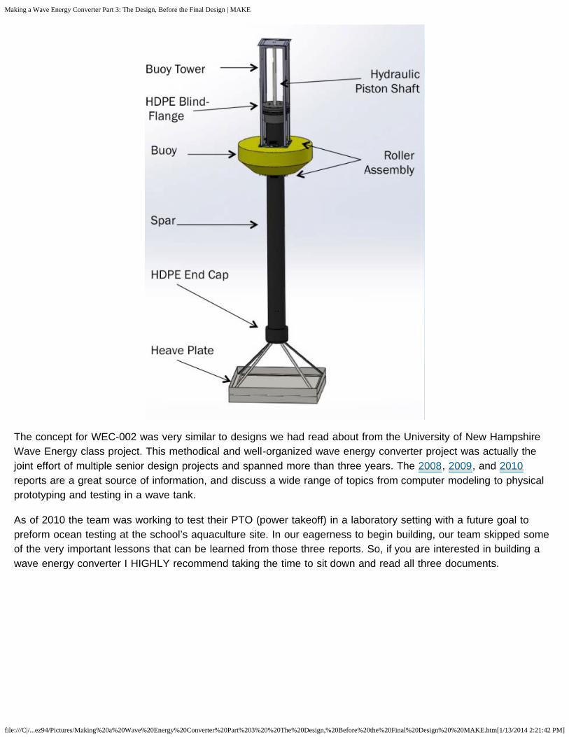
The concept for WEC-002 was very similar to designs we had read about from the University of New HampshireWave Energy class project. This methodical and well-organized wave energy converter project was actually thejoint effort of multiple senior design projects and spanned more than three years. The 2008, 2009, and 2010reports are a great source of information, and discuss a wide range of topics from computer modeling to physicalprototyping and testing in a wave tank.
As of 2010 the team was working to test their PTO (power takeoff) in a laboratory setting with a future goal topreform ocean testing at the school’s aquaculture site. In our eagerness to begin building, our team skipped someof the very important lessons that can be learned from those three reports. So, if you are interested in building awave energy converter I HIGHLY recommend taking the time to sit down and read all three documents.

Making a Wave Energy Converter Part 3: The Design, Before the Final Design | MAKE
file:///C|/...ez94/Pictures/Making%20a%20Wave%20Energy%20Converter%20Part%203%20%20The%20Design,%20Before%20the%20Final%20Design%20%20MAKE.htm[1/13/2014 2:21:42 PM]
Similar to the New Hampshire design, the WEC-002 used a large pipe with caps at both ends to create the spar.This spar would then slide up and down through the square hole cut in the center of the buoy. Since we planed tofabricate our own buoy, it was decided that a square hole would be easier to build using plywood. In order toproduce electricity, the yellow buoy and the spar must not move together, but instead move up at different times.
All the electronics and hydraulics were housed inside the large pipe, which was made from high-densitypolyethylene (HDPE).The major benefit of using HDPE was that endcaps could be thermally welded on to theends, and a stainless steel plate and rubber gasket could be bolted against the top HDPE flange adapter to createa removable waterproof lid. This would allow access to the PTO, which would slide in and out of the spar formaintenance and repairs.
Unlike cheap, mild steel, this HDPE pipe would not corrode in the saltwater. It was also chemically inherit,waterproof, and moderately UV-resistant. Our spar needed to have an inner diameter of at least 11″ to fit all thehydraulic equipment inside and had to be approximately 16′ long to maintain a neutral buoyancy. Normally, thistype of pipe is sold in 50′ lengths, but we found a local vendor who was willing to sell us a scrap piece, only 30′long, at a discounted price. With an outer diameter of 14″ and an inner diameter of 11.6″, the pipe weighed 22pounds/foot and we had to purchase the entire 30′ length. Additionally, the vendor would have to thermally weld onthe endcaps with a specialized machine, which meant this was definitely not a DIY option.
At the bottom of the WEC was a large metal heave plate to create hydrodynamic drag that would oppose the

Making a Wave Energy Converter Part 3: The Design, Before the Final Design | MAKE
file:///C|/...ez94/Pictures/Making%20a%20Wave%20Energy%20Converter%20Part%203%20%20The%20Design,%20Before%20the%20Final%20Design%20%20MAKE.htm[1/13/2014 2:21:42 PM]
upward heaving motion of the buoy floating in the ocean waves. The heave plate was an 8ft plate with 6″ wallswelded around the perimeter. This was done to take advantage of the added mass effect in fluid mechanics; bycapturing the volume of water directly above the plate, a larger force would be required to accelerate both the plateand water together and effectively increase the drag force of the heave plate.
When the plate is not moving in the water, the added mass effect would be negligible so only the actual weight ofthe heave plate would be pulling down on the spar. But if the spar bobbed up and down, this would cause theplate to accelerate and decelerate, and suddenly it would feel as if a much larger plate was pulling on the bottomof the spar. This little feature was critical (thank you, Dr. Andrew Hamilton!) because we needed the largestpossible drag force to oppose the upward heaving of the buoy while still having the spar be neutrally buoyant.
Relative movement between the buoy and spar would cause the hydraulic ram to move up and down and pumphydraulic fluid through the PTO to spin a generator and produce electricity. Without the added mass effect, wewould have needed to build a 20’x20’ heave plate, which would have been too heavy and expensive to build.Instead, we would purchase 4′-wide cheap sheet steel and use angle iron to build a fame. The sheet steel wouldbe welded to the frame and reinforced in the center with crossbeams to make a stiff and light weight plate. Tomaximize the added mass effect, sidewalls were also added to the bottom of the heave plate in hopes of capturinga larger volume of water that would stick to the bottom of the plate due to adhesion.
To keep the buoy centered around the spar we planned to secure two sets of dock rollers to the top and bottom ofthe buoy. Lengths of all-thread would then be used to sandwich the buoy in-between the metal roller frames.These rollers would loosely rub against the exterior of the HDPE spar so that if a large wave crashed against thebuoy the side load would be transferred to at least two of the rollers and prevent the foam from being crushed.This was a serious concern since one of the biggest variables in this project was the size of the ocean waves thatthe WEC would be subjected to during testing. From the NOAA wave data for Bodega Bay, Calif., we haddetermined that 95% of the waves should be between 1′–8′ tall (two standard deviations about the mean wave
2

Making a Wave Energy Converter Part 3: The Design, Before the Final Design | MAKE
file:///C|/...ez94/Pictures/Making%20a%20Wave%20Energy%20Converter%20Part%203%20%20The%20Design,%20Before%20the%20Final%20Design%20%20MAKE.htm[1/13/2014 2:21:42 PM]
height). The hydraulic ram we had spec’d only had a six 6′ of travel, so the rubber rollers would also function asend-stops to prevent the hydraulic ram from reaching the end of its stroke.
When designing the PTO we assumed an ideal operating condition with a wave height of 6′ and a wave period of10 seconds. From these parameters we could determine the average fluid flow rates from the hydraulic piston andwork our way down to the hydraulic motor. The PTO consisted of the following components: a double-actinghydraulic cylinder with a 2″ bore and 72″ stroke, an Eaton vane motor capable of rotating at 1,300–2,100rpm, twohydraulic accumulators with the larger accumulator used for the downstroke to hold the excess fluid, four checkvalves (one-way valves), a 1/2 horse power permanent magnet DC motor run backwards to act as our generator,and a bank of marine-grade deep-cycle batteries to collect all the energy. This was before we abandoned the ideaof storing the energy using onboard batteries, but we’ll go into more details in the next post.
Power-Take-off “sled” slides in and out of spar.
Now that we had a design that looked good on paper, we desperately needed insight from an outside authority tohelp us identify any obvious faults in the design. At this point we hadn’t really touched the grant money yet, and Iwas apprehensive about spending all that money without having someone double check our work. What we reallyneeded was someone who was familiar with building machines for the ocean or better yet someone who had builtand tested ocean power devices.

Making a Wave Energy Converter Part 3: The Design, Before the Final Design | MAKE
file:///C|/...ez94/Pictures/Making%20a%20Wave%20Energy%20Converter%20Part%203%20%20The%20Design,%20Before%20the%20Final%20Design%20%20MAKE.htm[1/13/2014 2:21:42 PM]
Share this:
Submit Tweet 12Like Pin ItLike this: Loading...
The problem was we needed to start ordering parts and materials right away if we were going to be able tofinishing building this thing in the remaining 12 weeks so we had to find someone fast. In a stroke of pure luck, Ireached out to the Monterey Bay Aquarium Research Institute (MBARI), having contacted them earlier afterreading about their wave energy converter project, and somehow managed to get an invitation to visit the researchcenter. Awesome! The team threw together a slideshow with all the figures from our simulations and CAD modelsand jumped in the car.
Driving down the road to Moss Landing, I thought about all the work we had pumped into this project and I wasproud of our team and what we had accomplished so far. I knew the design could be improved in some areas, andI expected that once construction started there would be minor adjustments or changes, but what I didn’t realizewas that the WEC-002 design needed an entire overhaul.
Tune in next week for part 4!
BY NICK RAYMOND
Nick is a recent UC Davis mechanical engineering graduate. He enjoys building and programming CNC machines,surf trips along the California coast, and home brewing belgian ales.
Most recently Nick has become fascinated with the field of ocean engineering, and is working to combine sensorswith mechatronic systems for ocean research projects.
Contact me at nraymond(at)makermedia(dot)com
Like

Making a Wave Energy Converter Part 3: The Design, Before the Final Design | MAKE
file:///C|/...ez94/Pictures/Making%20a%20Wave%20Energy%20Converter%20Part%203%20%20The%20Design,%20Before%20the%20Final%20Design%20%20MAKE.htm[1/13/2014 2:21:42 PM]
3 RESPONSES TO MAKING A WAVE ENERGY CONVERTER PART 3: THE DESIGN, BEFORE THE FINAL DESIGN
LEAVE A REPLY
Maaz Khalid on December 21st, 2013 at 5:31 am said:
Hi Nick!
You have done a great project. Where are part 4,5,6etc?I am a student of Industrial and ManufacturingEngineering and I am considering this project as my finalproject with my team. Please post next parts of theseries.
Great Job!
Maaz KhalidIndustrial and Manufacturing Engineering student,NED University,Karachi, Pakistan.
Reply ↓
Nick Raymondon December 30th, 2013 at 9:29 pm said:
Hi Maaz,
Glad to hear you and your team areinterested in a wave energy project. It wouldbe great to see other people take this projectand make improvements and share theirresults.
The remainder of the articles are still beingwritten. I am trying to get the next set ofposts (4,5,6…10) up and posted in a moretimely fashion. In the mean time, if you havespecific questions please feel free to emailme. Best luck with your final project.

Making a Wave Energy Converter Part 3: The Design, Before the Final Design | MAKE
file:///C|/...ez94/Pictures/Making%20a%20Wave%20Energy%20Converter%20Part%203%20%20The%20Design,%20Before%20the%20Final%20Design%20%20MAKE.htm[1/13/2014 2:21:42 PM]
MAKE: Complete eBook Collection(PDFs)
Gakken Mini Electric Guitar Arduino Shield Robot Kit Roominate Basic Kit
IN THE MAKER SHED
TrendingSharedCommented
// WHAT'S TRENDING
47 Raspberry Pi Projects to Inspire Your Next Build
joe burnham on December 31st, 2013 at 1:19 am said:
great job nick ,you fellows are pretty impressivemade a comment earlier but had notread blog 3 . looking forward to seehow ya’ll make it happen .
Reply
-Nick
Reply ↓
↓

Making a Wave Energy Converter Part 3: The Design, Before the Final Design | MAKE
file:///C|/...ez94/Pictures/Making%20a%20Wave%20Energy%20Converter%20Part%203%20%20The%20Design,%20Before%20the%20Final%20Design%20%20MAKE.htm[1/13/2014 2:21:42 PM]
By: Nick NormalHits: 14272
How I Built a Raspberry Pi Tablet
By: Michael CastorHits: 6251
Seventeen Sneaky Secret Hides
By: Sean Michael RaganHits: 6080
Building an Open Source Laptop
By: Bunnie HuangHits: 3917
Teardrop Camper Trailer
By: WernerHits: 3851
Super Simple FM Transmitter
By: Sean Michael RaganHits: 2852
2013 in Review: Our Favorite New Tools
By: Stuart DeutschHits: 1938
// WHAT'S SHARED
How-To: Cut a Wine Bottle in 30 Seconds
By: Adam FlahertyShares: 198473
Denim Do-it-All Bins
By: nataliezdrieuShares: 99982
How-To: Homemade Rock Candy
By: rachelhobsonShares: 93061
How-To: Mason Jar Bathroom Organizer
By: Haley Pierson-CoxShares: 22926
// MOST COMMENTED

Making a Wave Energy Converter Part 3: The Design, Before the Final Design | MAKE
file:///C|/...ez94/Pictures/Making%20a%20Wave%20Energy%20Converter%20Part%203%20%20The%20Design,%20Before%20the%20Final%20Design%20%20MAKE.htm[1/13/2014 2:21:42 PM]
How I Built a Raspberry Pi Tablet
By: Michael CastorComments: 46
Intel Edison: A Computer in an SD Card
By: Matt RichardsonComments: 10
Skill Builder: Arduino 101
By: Quin EtnyreComments: 9
Diresta: Pallet Toolbox
By: jimmydirestaComments: 9
Bre Pettis on MakerBot’s Three New Printers
By: Anna Kaziunas FranceComments: 8
Reverse Engineering the Estimote
By: Alasdair AllanComments: 7
Building a Braille Smartphone
By: anandghanComments: 5

Making a Wave Energy Converter Part 3: The Design, Before the Final Design | MAKE
file:///C|/...ez94/Pictures/Making%20a%20Wave%20Energy%20Converter%20Part%203%20%20The%20Design,%20Before%20the%20Final%20Design%20%20MAKE.htm[1/13/2014 2:21:42 PM]
Read Digital Edition Shop Maker Shed
Trending TopicsArduino3D PrintingRaspberry PiCraftMaker ProKids & Family
Get our NewslettersSign up to receiveexclusive content andoffers.
MAKE Newsletter Maker Faire Newsletter Maker Shed Maker Pro Newsletter
HelpContactSubscribeAdvertisePrivacy
About UsFAQForumsWrite forMAKE
About Maker Media Subscribeto MAKE!Get theprint anddigitalversionswhen yousubscribe
Make Your Own Cellphone
By: Matt RichardsonComments: 5
Make: andMakerFaire areregisteredtrademarksof MakerMedia, Inc.
Copyright© 2004-2014

Making a Wave Energy Converter Part 3: The Design, Before the Final Design | MAKE
file:///C|/...ez94/Pictures/Making%20a%20Wave%20Energy%20Converter%20Part%203%20%20The%20Design,%20Before%20the%20Final%20Design%20%20MAKE.htm[1/13/2014 2:21:42 PM]
JOINMakerMedia, Inc.
All rights reserved