


Make the Most of Powder Processes - Chemical … · 3 Table of ConTenTs Make the Most of flow...
26
Powder eHandbook MAKE THE MOST OF POWDER PROCESSES
Transcript of Make the Most of Powder Processes - Chemical … · 3 Table of ConTenTs Make the Most of flow...
22
For pneumatic conveying and air filtration inquiries contact:Mac Process7901 NW 107th TerraceKansas City, MO [email protected]
For weighing and feeding inquires contact:Schenck AccuRate746 E. Milwaukee StreetWhitewater, WI 53190800-558-0184 or Fax: 262-473-4384 [email protected]
Together, we bring you unmatched systems for pneumatic conveying, filtration, weighing and feeding
Mac Process and Schenck AccuRate are now one
Industry leaders Mac Process and Schenck AccuRate have combined forces as one to deliver premier systems for your dry material handling process needs. From sanitary through heavy industrial applications, our custom solutions are engineered and work together to solve your most difficult challenges, efficiently and economically.
As a Schenck Process family company, we’ve integrated our sales, material testing centers, and over 100 engineers to deliver advanced products, designed and manu-factured for 100% compatibility and accurate process control. Rely on the continuous high performance, reliability and smooth operation of your system, backed by global support. Our deep application knowledge has resulted in thousands of installations for multiple industries worldwide. Contact us with your dry material handling needs.

3
Table of ConTenTsMake the Most of flow additives 7Optimization requires understanding their impact on overall powder behavior
Improve the Performance of Your Gravimetric feeder 16Use these tips to avoid poor accuracy and frequent downtime
Protect against Combustible Dust explosion 21Economical approaches exist to protect spray dryer processes and solutions
KurIYaMa of America’s new line of Tigerflex Voltbuster food-grade material-handling hoses have been designed for high-static applications such as the transfer of powders, pellets and other granular materials.
The hose’s design helps dissipate static charges to ground, helping prevent static build-up and re-ducing the potential for dangerous electrostatic discharges. They have been constructed with static dissipative plastic materials, allowing for the free flow of static to the hose’s embedded grounding wire. The light-weight design of the hoses can help reduce injuries related to heavier metal hoses.
The “Volt Series” hose-tube construction includes abrasion-resistant food-grade polyurethane to ensure the purity of transferred materials. In addition, the grounding wire has been encapsulated in a rigid PVC helix on the exterior of the hose, eliminating the risk of contaminating the transferred materials. The VLT-SD Series is con-structed the same, but has an FDA polyester fabric reinforcement to handle both suction and higher pressure discharge applications. New 2- and 8-in. ID sizes have been recently added to this product line.
www.kuriyama.com
food-Grade Hoses Handle High-static applicationsHose design helps dissipate static charges to ground.

55
Schenck AccuRate 2www.accuratefeeders.com
Rembe 4www.rembe.us
Arizona Instrument 6www.azic.com
Kuriyama 9www.kuriyama.com
Federal Equipment 12www.fedequip.com
Houston Vibrator 15www.houstonvibrator.com
TecWeigh 20www.tecweigh.com
Vac-u-Max 26www.vac-u-max.com
Ad IndEx
77
Make the Most of flow additivesOptimization requires understanding their impact on overall powder behavior
By Brian Armstrong and Jamie Clayton, Freeman Technology
fIne PoWDers developed to meet certain prod-uct performance targets often suffer from inconsistent and unpredictable f low that can lead to caking and in-process blockages. Therefore, processors frequently include additives in a blend to enhance f low properties. Although typically incorporated to improve process ef-ficiency, additives also can substantially inf luence final product quality.
When optimizing the use of f low additives, it’s important to recognize their impact on behavior may extend beyond a simple improvement in f lowability. Choosing the most-appropriate grade of f low additive for a particular blend and incorporating it at an optimal level for the application also are crucial. This article provides some guidance on the use of powder additives, outlining issues useful to assess as part of blend devel-opment. Experimental data illustrate how multifaceted powder characterization can help this development process.
usInG floW aDDITIVes
Flow additives ease powder f low by physically lubricat-ing interparticulate movement and by disrupting the cohesive bonds between particles within the powder. Reducing or breaking interparticulate forces, such as electrostatic or Van der Waals interactions, allows par-ticles to move more easily with respect to one another, thereby enhancing f lowability. A corresponding reduc-tion in the adhesive forces between a powder and a ma-terial of construction can ease movement within process equipment and storage vessels. As a result, additives in certain circumstances simultaneously may serve both as lubricants and f low enhancers.
Used effectively, f low additives can substantially increase manufacturing efficiency by maintaining consistent f low through the process and preventing un-planned shutdowns due to machine blockages. They also can impart superior performance to a finished product, either directly, e.g., better f low properties for a fine milk
88
powder, or indirectly, such as consistent tablet weight resulting from a smoothly operating tableting press.
To select the most-appropriate f low additive, powder processors must consider a wide range of variables. In some applications, very specific end-product require-ments may dictate choice. For instance, certain grades of hydrophobic silica aren’t permitted in food applications — so, in such cases, choosing an appropriate additive relies on a detailed understanding of final product use and the regulatory framework that governs it.
However, a processor also should take many other factors into consideration. Indeed, making the optimum choice requires fully determining how an additive will affect the manufacturing process and inf luence critical quality attributes of the final product.
While most f low additives are selected on the basis of their ability to improve f low, the question remains as to what constitutes “improved f low” in a given process. Furthermore, an additive simultaneously and uninten-tionally may substantially affect a range of other powder properties that contribute to process performance. Com-pressibility, permeability, response to consolidation and, indeed, the ability to aerate, all may change with the inclusion of just small quantities of f low additive; these
potentially may impact, possibly detrimentally, many aspects of behavior in a process. Therefore, optimiz-ing the use of f low additives requires a comprehensive understanding of exactly how the additive will inf luence both process performance and product quality.
MulTIVarIaTe PoWDer analYsIs
It is helpful to consider powders as multicomponent systems comprising solids (the particles), gases (air entrained between the particles) and water, often in the form of moisture. Powder behavior depends upon complex interactions between these components as well as external variables, such as the environmental condi-tions experienced during processing. (For specifics on the impact of moisture, see: “Optimize Humidity for Effective Powder Handling,” www.ChemicalProcessing.com/articles/2013/optimize-humidity-for-efficient-pow-der-handling/.) Individual processes subject powders to various stresses and f low regimes, making it important to identify the properties that dictate performance in any specific operation.
For example, the low-stress dynamic conditions that prevail in a f luidized bed differ dramatically from the high-stress static conditions imposed on a powder stored
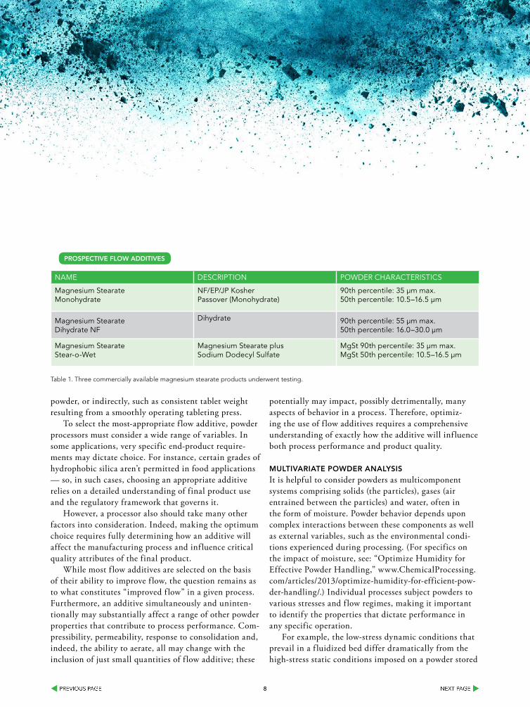
Name DescriptioN powDer characteristics
magnesium stearatemonohydrate
NF/ep/Jp Kosherpassover (monohydrate)
90th percentile: 35 µm max.50th percentile: 10.5–16.5 µm
magnesium stearateDihydrate NF
Dihydrate 90th percentile: 55 µm max.50th percentile: 16.0–30.0 µm
magnesium stearatestear-o-wet
magnesium stearate plussodium Dodecyl sulfate
mgst 90th percentile: 35 µm max.mgst 50th percentile: 10.5–16.5 µm
Table 1. Three commercially available magnesium stearate products underwent testing.
ProsPeCTIVe floW aDDITIVes

99
TIGERFLEXISO 9001-2000
REGISTERED Q.M.S.
™
THE ASSOCIATION FOR HOSE ANDACCESSORIES DISTRIBUTION Made In USA
Static Dissipative Food Grade Material Handling HosesSuperior Static Protection!
Durable Abrasion Resistant!
Food Grade!
Light Weight!
Thermoplastic Industrial Hoses
EDITION 0114
VLT-SD™
VOLT™WINNER!
CHEMICAL PROCESSING
BY
1010
under its own weight in a hopper. Therefore, a unique set of powder properties will define performance in each case. Comprehensively defining how a f low additive will inf luence powder behavior consequently requires a multivariate approach to powder analysis.
Dynamic powder properties directly quantify f lowability and have proven applica-tion in optimizing manufacturing practices. Dynamic measurement involves rotating a precision-engineered blade through an accurately controlled volume of powder along a prescribed path. Measuring the axial and rotational forces acting on the powder determine its resistance to the motion of the blade. The resulting data then are used to generate f low parameters such as basic f lowability energy (BFE) and specific energy (SE). Dynamic properties can be measured for powders in consolidated, moderate-stress, aerated or even f luidized states, allowing the generation of data that directly relate to a specific process. Equally important, the repeatability, reproducibility and sensitivity of dynamic measurement enable the user to identify and quantify even subtle differences in powder behavior, making the technique a valuable tool for detailed f low additive studies.
Universal powder testers, such as the FT4 powder rheometer, complement dynamic powder testing with other valuable methods such as bulk property measurement and shear analysis. As a result, they can provide the multifaceted approach to powder charac-terization required for success with f low additives.
10
9
8
7
6
5
4
3
2
1
0-0.1 0 0.1 0.2 0.3 0.4 0.5 0.6
% w/w Magnesium Stearate Concentration
Spec
ific
Ene
rgy
Avicel PH-101 – SE vs. MgSt Type + Conc.
Avicel PH-101MonohydrateDihydrateStear-O-Wet
120
100
80
60
40
20
0-0.1 0 0.1 0.2 0.3 0.4 0.5 0.6
% w/w Magnesium Stearate Concentration
Aer
ated
Ene
rgy
Avicel PH-101 – AE vs. MgSt Type + Conc.
Avicel PH-101MonohydrateDihydrateStear-O-Wet
Avicel PH-101Sorbitol
1.6
1.4
1.2
1.0
0.8
0.6
0.4
0.2
0.0Substrate Monohydrate Dihydrate Stear-O-Wet
Batch
No
rmal
ized
Wal
l Fri
ctio
n A
ngle
Wall Friction Angle
Avicel PH-101Sorbitol
3.0
2.5
2.0
1.5
1.0
0.5
0.0Substrate Monohydrate Dihydrate Stear-O-Wet
Batch
No
rmal
ized
Aer
ated
Ene
rgy
@ 1
0 m
m/s
Aerated Energy (AE)
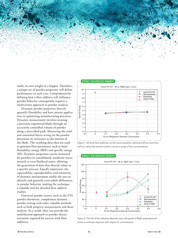
Figure 1. All three flow additives cut the microcrystalline cellulose’s SE by more than
half to a value that remains uniform across a range of low concentrations.
effeCT on sPeCIfIC enerGY
10
9
8
7
6
5
4
3
2
1
0-0.1 0 0.1 0.2 0.3 0.4 0.5 0.6
% w/w Magnesium Stearate Concentration
Spec
ific
Ene
rgy
Avicel PH-101 – SE vs. MgSt Type + Conc.
Avicel PH-101MonohydrateDihydrateStear-O-Wet
120
100
80
60
40
20
0-0.1 0 0.1 0.2 0.3 0.4 0.5 0.6
% w/w Magnesium Stearate Concentration
Aer
ated
Ene
rgy
Avicel PH-101 – AE vs. MgSt Type + Conc.
Avicel PH-101MonohydrateDihydrateStear-O-Wet
Avicel PH-101Sorbitol
1.6
1.4
1.2
1.0
0.8
0.6
0.4
0.2
0.0Substrate Monohydrate Dihydrate Stear-O-Wet
Batch
No
rmal
ized
Wal
l Fri
ctio
n A
ngle
Wall Friction Angle
Avicel PH-101Sorbitol
3.0
2.5
2.0
1.5
1.0
0.5
0.0Substrate Monohydrate Dihydrate Stear-O-Wet
Batch
No
rmal
ized
Aer
ated
Ene
rgy
@ 1
0 m
m/s
Aerated Energy (AE)
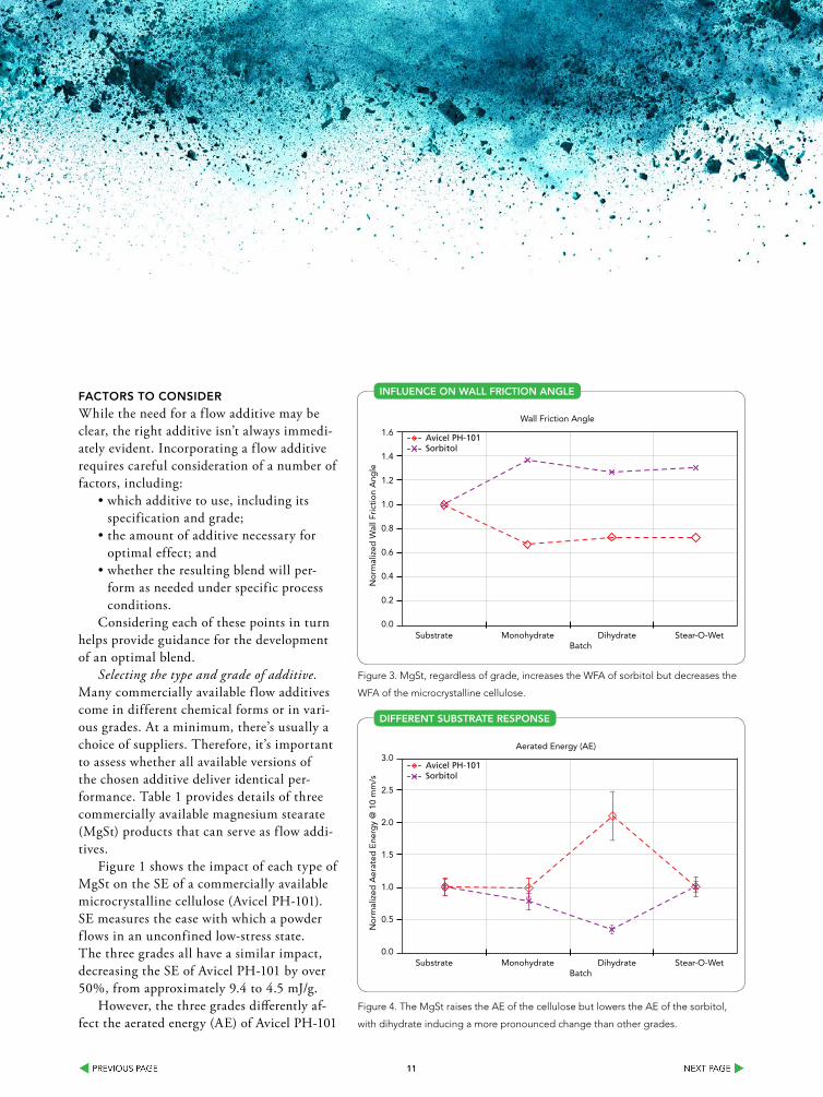
Figure 2. The AE of the cellulose depends upon the grade of MgSt employed and
shows a nonlinear response with respect to concentration.
IMPaCT on aeraTeD enerGY
1111
faCTors To ConsIDer
While the need for a f low additive may be clear, the right additive isn’t always immedi-ately evident. Incorporating a f low additive requires careful consideration of a number of factors, including:
• which additive to use, including its specification and grade;
• the amount of additive necessary for optimal effect; and
• whether the resulting blend will per-form as needed under specific process conditions.
Considering each of these points in turn helps provide guidance for the development of an optimal blend.
Selecting the type and grade of additive. Many commercially available f low additives come in different chemical forms or in vari-ous grades. At a minimum, there’s usually a choice of suppliers. Therefore, it’s important to assess whether all available versions of the chosen additive deliver identical per-formance. Table 1 provides details of three commercially available magnesium stearate (MgSt) products that can serve as f low addi-tives.
Figure 1 shows the impact of each type of MgSt on the SE of a commercially available microcrystalline cellulose (Avicel PH-101). SE measures the ease with which a powder f lows in an unconfined low-stress state. The three grades all have a similar impact, decreasing the SE of Avicel PH-101 by over 50%, from approximately 9.4 to 4.5 mJ/g.
However, the three grades differently af-fect the aerated energy (AE) of Avicel PH-101
10
9
8
7
6
5
4
3
2
1
0-0.1 0 0.1 0.2 0.3 0.4 0.5 0.6
% w/w Magnesium Stearate Concentration
Spec
ific
Ene
rgy
Avicel PH-101 – SE vs. MgSt Type + Conc.
Avicel PH-101MonohydrateDihydrateStear-O-Wet
120
100
80
60
40
20
0-0.1 0 0.1 0.2 0.3 0.4 0.5 0.6
% w/w Magnesium Stearate Concentration
Aer
ated
Ene
rgy
Avicel PH-101 – AE vs. MgSt Type + Conc.
Avicel PH-101MonohydrateDihydrateStear-O-Wet
Avicel PH-101Sorbitol
1.6
1.4
1.2
1.0
0.8
0.6
0.4
0.2
0.0Substrate Monohydrate Dihydrate Stear-O-Wet
Batch
No
rmal
ized
Wal
l Fri
ctio
n A
ngle
Wall Friction Angle
Avicel PH-101Sorbitol
3.0
2.5
2.0
1.5
1.0
0.5
0.0Substrate Monohydrate Dihydrate Stear-O-Wet
Batch
No
rmal
ized
Aer
ated
Ene
rgy
@ 1
0 m
m/s
Aerated Energy (AE)
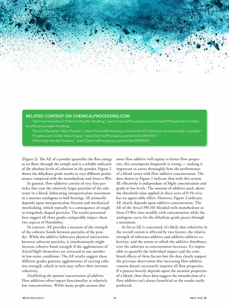
Figure 4. The MgSt raises the AE of the cellulose but lowers the AE of the sorbitol,
with dihydrate inducing a more pronounced change than other grades.
DIfferenT subsTraTe resPonse
10
9
8
7
6
5
4
3
2
1
0-0.1 0 0.1 0.2 0.3 0.4 0.5 0.6
% w/w Magnesium Stearate Concentration
Spec
ific
Ene
rgy
Avicel PH-101 – SE vs. MgSt Type + Conc.
Avicel PH-101MonohydrateDihydrateStear-O-Wet
120
100
80
60
40
20
0-0.1 0 0.1 0.2 0.3 0.4 0.5 0.6
% w/w Magnesium Stearate Concentration
Aer
ated
Ene
rgy
Avicel PH-101 – AE vs. MgSt Type + Conc.
Avicel PH-101MonohydrateDihydrateStear-O-Wet
Avicel PH-101Sorbitol
1.6
1.4
1.2
1.0
0.8
0.6
0.4
0.2
0.0Substrate Monohydrate Dihydrate Stear-O-Wet
Batch
No
rmal
ized
Wal
l Fri
ctio
n A
ngle
Wall Friction Angle
Avicel PH-101Sorbitol
3.0
2.5
2.0
1.5
1.0
0.5
0.0Substrate Monohydrate Dihydrate Stear-O-Wet
Batch
No
rmal
ized
Aer
ated
Ene
rgy
@ 1
0 m
m/s
Aerated Energy (AE)
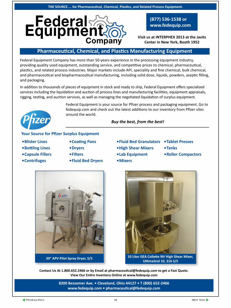
Figure 3. MgSt, regardless of grade, increases the WFA of sorbitol but decreases the
WFA of the microcrystalline cellulose.
InfluenCe on Wall frICTIon anGle
1212
Contact Us At 1.800.652.2466 or by Email at [email protected] to get a Fast Quote. View Our Entire Inventory Online at www.fedequip.com
(877) 536-1538 or www.fedequip.com
Pharmaceutical, Chemical, and Plastics Manufacturing Equipment
• Blister Lines• Bottling Lines • Capsule Fillers • Centrifuges
• Coating Pans• Dryers• Filters• Fluid Bed Dryers
• Fluid Bed Granulators• High Shear Mixers• Lab Equipment• Mixers
• Tablet Presses• Tanks• Roller Compactors
Federal Equipment Company has more than 50-years experience in the processing equipment industry, providing quality used equipment, outstanding service, and competitive prices to chemical, pharmaceutical, plastics, and related process industries. Major markets include API, speciality and fine chemical, bulk chemical, and pharmaceutical and biopharmaceutical manufacturing, including solid dose, liquids, powders, aseptic filling, and packaging.
In addition to thousands of pieces of equipment in stock and ready to ship, Federal Equipment offers specialized services including the liquidation and auction of process lines and manufacturing facilities, equipment appraisals, rigging, testing, and auction services, as well as managing the negotiated liquidation of surplus equipment.
8200 Bessemer Ave. • Cleveland, Ohio 44127 • T (800) 652-2466 www.fedequip.com • [email protected]
39” APV Pilot Spray Dryer, S/S 10 Liter GEA Collette NV High Shear Mixer, UltimaGral 10, 316 S/S
Your Source for Pfizer Surplus Equipment
Federal Equipment is your source for Pfizer process and packaging equipment. Go to fedequip.com and check out the latest additions to our inventory from Pfizer sites around the world.
Buy the best, from the best!
Visit us at INTERPHEX 2013 at the Javits Center in New York, Booth 1952
THE SOURCE ... for Pharmaceutical, Chemical, Plastics, and Related Process Equipment.
1313
(Figure 2). The AE of a powder quantifies the flow energy as air flows through the sample and is a reliable indicator of the absolute levels of cohesion in the powder. Figure 2 shows the dihydrate grade results in very different perfor-mance compared with the monohydrate and Stear-o-Wet.
In general, f low additives consist of very fine par-ticles that coat the relatively larger particles of the sub-strate in a blend, lubricating interparticulate movement in a manner analogous to ball bearings. SE primarily depends upon interparticulate friction and mechanical interlocking, which typically is a consequence of rough or irregularly shaped particles. The results presented here suggest all three grades comparably impact these two aspects of f lowability.
In contrast, AE provides a measure of the strength of the cohesive bonds between particles of the pow-der. While the additive lubricates physical interactions between substrate particles, it simultaneously might increase cohesive bond strength if the agglomerates of Avicel/MgSt themselves are attracted to one another in low-stress conditions. The AE results suggest these different grades generate agglomerates of varying cohe-sive strength, which in turn may ref lect their intrinsic cohesivity.
Establishing the optimal concentration of additive. Flow additives often impart functionality at relatively low concentrations. While many people assume that
more f low additive will equate to better f low proper-ties, this assumption frequently is wrong — making it important to assess thoroughly how the performance of a blend varies with f low additive concentration. The data shown in Figure 1 indicate that with this system SE effectively is independent of MgSt concentration and grade at low levels. The amount of additive used, above the threshold value applied in these tests of 0.1% w/w, has no appreciable effect. However, Figure 2 indicates AE clearly depends upon additive concentration. The AE of the Avicel PH-101 blended with monohydrate or Stear-O-Wet rises steadily with concentration while the analogous curve for the dihydrate grade passes through a maximum.
As far as AE is concerned, it’s likely that cohesivity in the overall system is affected by two factors: the relative strength of substrate-additive and additive-additive co-hesivity; and the extent to which the additive distributes over the substrate as concentration increases. It’s impos-sible to quantify the individual impact and the com-bined effects of these factors but the data clearly support the previous observation that increasing f low additive content doesn’t necessarily improve all f low properties. If a process heavily depends upon the aeration properties of a blend, then these data suggest the introduction of a f low additive isn’t always beneficial or the results easily predicted.
RELATED CONTENT ON CHEMICALPROCESSING.COM“Optimize Humidity for Effective Powder Handling,” www.ChemicalProcessing.com/articles/2013/optimize-humidity-
for-efficient-powder-handling/“Particle Mysteries Take a Powder,” www.ChemicalProcessing.com/articles/2012/particle-mysteries-take-a-powder/“Progress with Solids Takes Shape,” www.ChemicalProcessing.com/articles/2010/011/“Effectively Handle Powders,” www.ChemicalProcessing.com/articles/2009/095/
1414
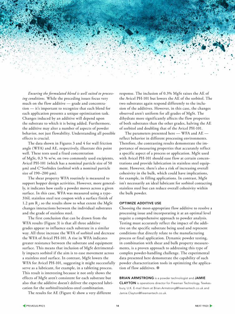
Ensuring the formulated blend is well suited to process-ing conditions. While the preceding issues focus very much on the f low additive — grade and concentra-tion — it’s important to recognize that each blend for each application presents a unique optimization task. Changes induced by an additive will depend upon the substrate to which it is being added. Furthermore, the additive may alter a number of aspects of powder behavior, not just f lowability. Understanding all possible effects is crucial.
The data shown in Figures 3 and 4 for wall friction angle (WFA) and AE, respectively, illustrate this point well. These tests used a fixed concentration of MgSt, 0.3 % w/w, on two commonly used excipients, Avicel PH-101 (which has a nominal particle size of 50 µm) and C*Sorbidex (sorbitol with a nominal particle size of 190–200 µm).
The shear property WFA routinely is measured to support hopper design activities. However, more general-ly, it indicates how easily a powder moves across a given surface. In this case, WFA was measured using a type-316L stainless steel test coupon with a surface finish of 1.2 µm Ra; so the results show to what extent the MgSt changes interactions between the individual substrates and the grade of stainless steel.
The first conclusion that can be drawn from the WFA results (Figure 3) is that all three additive grades appear to inf luence each substrate in a similar way. All three increase the WFA of sorbitol and decrease the WFA of Avicel PH-101. A rise in WFA indicates greater resistance between the substrate and equipment surface. This means that inclusion of MgSt detrimental-ly impacts sorbitol if the aim is to ease movement across a stainless steel surface. In contrast, MgSt lowers the WFA for Avicel PH-101, suggesting it might successfully serve as a lubricant, for example, in a tableting process. This result is interesting because it not only shows the effects of MgSt aren’t consistent for each substrate but also that the additive doesn’t deliver the expected lubri-cation for the sorbitol/stainless-steel combination.
The results for AE (Figure 4) show a very different
response. The inclusion of 0.3% MgSt raises the AE of the Avicel PH-101 but lowers the AE of the sorbitol. The two substrates again respond differently to the inclu-sion of the additives. However, in this case, the changes observed aren’t uniform for all grades of MgSt. The dihydrate more significantly affects the f low properties of both substrates than the other grades, halving the AE of sorbitol and doubling that of the Avicel PH-101.
The parameters presented here — WFA and AE — ref lect behavior in different processing environments. Therefore, the contrasting results demonstrate the im-portance of measuring properties that accurately ref lect a specific aspect of a process or application. MgSt used with Avicel PH-101 should ease f low at certain concen-trations and provide lubrication in stainless steel equip-ment. However, there’s also a risk of increasing overall cohesivity in the bulk, which could have implications, for example, in filling applications. In contrast, MgSt isn’t necessarily an ideal lubricant for sorbitol contacting stainless steel but can reduce overall cohesivity within the bulk powder.
oPTIMIZe aDDITIVe use
Choosing the most-appropriate f low additive to resolve a processing issue and incorporating it at an optimal level require a comprehensive approach to powder analysis. Testing must accurately ref lect the impact of the addi-tive on the specific substrate being used and represent conditions that directly relate to the manufacturing process or final application. Dynamic powder testing, in combination with shear and bulk property measure-ments, is a proven approach to addressing this type of complex powder-handling challenge. The experimental data presented here demonstrate the capability of such powder characterization tools in optimizing the applica-tion of f low additives.
brIan arMsTronG is a powder technologist and JaMIe
ClaYTon is operations director for Freeman Technology, Tewkes-
bury, U.K. E-mail them at [email protected] and
1616
Improve the Performance of Your Gravimetric feederUse these tips to avoid poor accuracy and frequent downtime
By Todd D. Messmer, Schenck Process
HoW Can I improve my screw feeder’s gravimetric performance? As applications engineers, we get asked this question quite often. In answering, the first thing you need to tell us is the material you are feeding. Gravimetric feeder performance is most always affected by how well the mate-rial feeds volumetrically. The closer you can fill the flights of the feed screw volumetrically to 100%, the better the feeder will perform gravimetrically. In order to get the material to feed better volumetrically, the material’s bulk characteristics must be analyzed first. Let’s look at some of the most com-mon material characteristics that affect volumetric feeder performance:
• Free flowing: Plastic pellets are generally freeflowing materials. They feed under gravity without the need for special design considerations or flow enhancements.
• Adhesive: Some materials like to stick to everything. Pigments are notorious for adhering to all types of contact surfaces. Often, we need to clean feed screws and tubes just to keep the material from building up on them. Avoid feeders with internal agitation systems. We may need to look at different coatings such as fluoropolymers or more polished contact services. Systems to self-clean the inside of the feed tube should be considered.
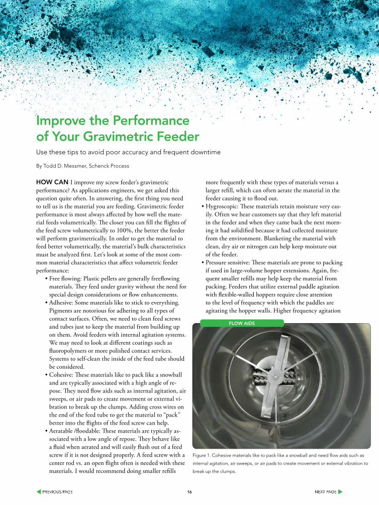
• Cohesive: These materials like to pack like a snowball and are typically associated with a high angle of re-pose. They need flow aids such as internal agitation, air sweeps, or air pads to create movement or external vi-bration to break up the clumps. Adding cross wires on the end of the feed tube to get the material to “pack” better into the flights of the feed screw can help.
• Aeratable /floodable: These materials are typically as-sociated with a low angle of repose. They behave like a fluid when aerated and will easily flush out of a feed screw if it is not designed properly. A feed screw with a center rod vs. an open flight often is needed with these materials. I would recommend doing smaller refills
more frequently with these types of materials versus a larger refill, which can often aerate the material in the feeder causing it to flood out.
• Hygroscopic: These materials retain moisture very eas-ily. Often we hear customers say that they left material in the feeder and when they came back the next morn-ing it had solidified because it had collected moisture from the environment. Blanketing the material with clean, dry air or nitrogen can help keep moisture out of the feeder.
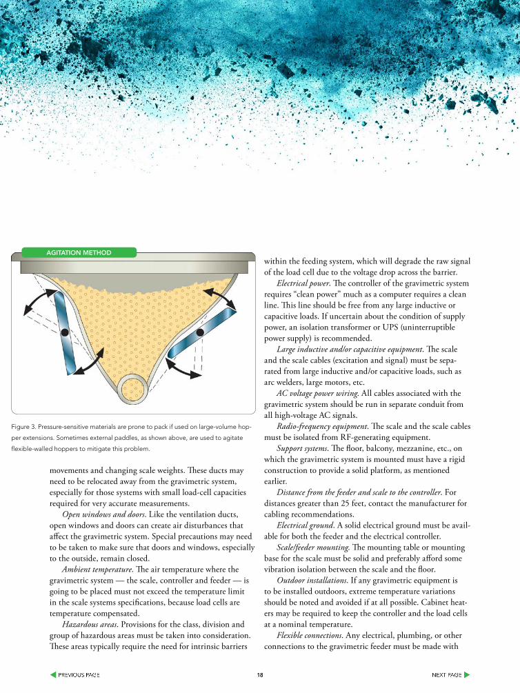
• Pressure sensitive: These materials are prone to packing if used in large-volume hopper extensions. Again, fre-quent smaller refills may help keep the material from packing. Feeders that utilize external paddle agitation with flexible-walled hoppers require close attention to the level of frequency with which the paddles are agitating the hopper walls. Higher frequency agitation
Figure 1. Cohesive materials like to pack like a snowball and need flow aids such as
internal agitation, air sweeps, or air pads to create movement or external vibration to
break up the clumps.
floW aIDs
1717
or vibration can often pack these materials.• Low melt temp: These materials tend to break down,
melt, or caramelize when excess friction/energy is used on them. I would recommend using a larger-diameter feed screw turning at a lower rpm than a smaller-di-ameter feed screw running at a higher rpm with these types of materials.
If all else fails, inquire about the testing capabilities of your material-handling equipment supplier. Often, they have had experience feeding the material and can suggest ways of improving performance. Material testing is usually free of charge and can be witnessed firsthand.
Now, after taking steps to improve material feeding volumetrically, let’s take a look at several factors that will
affect the gravimetric performance of the feeder.Vibration. Because of the sensitivity of the scale, vibra-
tion is detrimental to the operation of the gravimetric system; special provisions must be taken to eliminate any vi-bration of the scale. Some possible ways to minimize vibra-tion are to isolate the decking that the weighing system rests on; reinforce the decking around the weighing equipment so the decking flexes minimally; mount the weighing equip-ment on a high-mass pedestal (i.e., concrete-block table); mount the weighing equipment on vibration isolators; or mount the weighing equipment on structural members, not on the decking itself.
Heating, air conditioning, and ventilation ducts. These cause air disturbances, which could translate into false scale
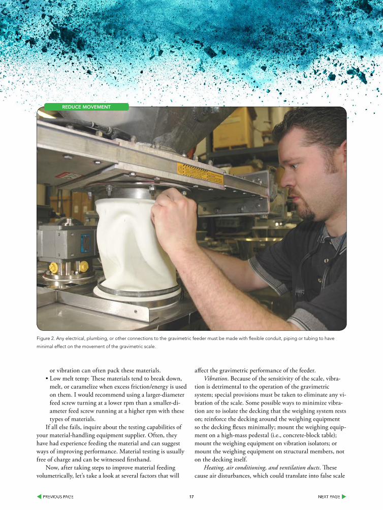
Figure 2. Any electrical, plumbing, or other connections to the gravimetric feeder must be made with flexible conduit, piping or tubing to have
minimal effect on the movement of the gravimetric scale.
reDuCe MoVeMenT
1818
movements and changing scale weights. These ducts may need to be relocated away from the gravimetric system, especially for those systems with small load-cell capacities required for very accurate measurements.
Open windows and doors. Like the ventilation ducts, open windows and doors can create air disturbances that affect the gravimetric system. Special precautions may need to be taken to make sure that doors and windows, especially to the outside, remain closed.
Ambient temperature. The air temperature where the gravimetric system — the scale, controller and feeder — is going to be placed must not exceed the temperature limit in the scale systems specifications, because load cells are temperature compensated.
Hazardous areas. Provisions for the class, division and group of hazardous areas must be taken into consideration. These areas typically require the need for intrinsic barriers
within the feeding system, which will degrade the raw signal of the load cell due to the voltage drop across the barrier.
Electrical power. The controller of the gravimetric system requires “clean power” much as a computer requires a clean line. This line should be free from any large inductive or capacitive loads. If uncertain about the condition of supply power, an isolation transformer or UPS (uninterruptible power supply) is recommended.
Large inductive and/or capacitive equipment. The scale and the scale cables (excitation and signal) must be sepa-rated from large inductive and/or capacitive loads, such as arc welders, large motors, etc.
AC voltage power wiring. All cables associated with the gravimetric system should be run in separate conduit from all high-voltage AC signals.
Radio-frequency equipment. The scale and the scale cables must be isolated from RF-generating equipment.
Support systems. The floor, balcony, mezzanine, etc., on which the gravimetric system is mounted must have a rigid construction to provide a solid platform, as mentioned earlier.
Distance from the feeder and scale to the controller. For distances greater than 25 feet, contact the manufacturer for cabling recommendations.
Electrical ground. A solid electrical ground must be avail-able for both the feeder and the electrical controller.
Scale/feeder mounting. The mounting table or mounting base for the scale must be solid and preferably afford some vibration isolation between the scale and the floor.
Outdoor installations. If any gravimetric equipment is to be installed outdoors, extreme temperature variations should be noted and avoided if at all possible. Cabinet heat-ers may be required to keep the controller and the load cells at a nominal temperature.
Flexible connections. Any electrical, plumbing, or other connections to the gravimetric feeder must be made with
Figure 3. Pressure-sensitive materials are prone to pack if used on large-volume hop-
per extensions. Sometimes external paddles, as shown above, are used to agitate
flexible-walled hoppers to mitigate this problem.
aGITaTIon MeTHoD
1919
flexible conduit, piping or tubing to have minimal effect on the movement of the gravimetric scale. Use factory-recom-mended flexible connectors for feeder inlet and discharge ends when the scale system is part of a gravimetric feeder.
Maintenance access. Consideration should be given to allow maintenance personnel access to maintain the scale, gravimetric feeder and controller.
Corrosive atmospheres. Any corrosive vapors, dust, etc., should be noted and recommendations should be given on how to prevent corrosion by using resistant materials.
Refill mechanism. The mechanism used to automatically refill gravimetric feeders must be tight-closing so the mate-rial can’t enter the feeder’s extension hopper other than during the refill time. In addition, the refill device must be sized to refill the required amount of material so the feeder doesn’t starve out.
Refill venting. Rapid introduction of dry material into a feeder hopper extension during a refill causes pressure to build up inside the hopper extension equivalent to the volume of air displaced by the volume of dry material. This pressure must be relieved, either by leaving the refill gate open so the displaced air can move into the refill hopper or by providing a vent in the feeder hopper extension.
Vacuum systems. Vacuum or pressure systems, either at the infeed or discharge of a feeder, may affect the gravi-metric system by causing adverse suction or pressure on the system. These ancillary systems must be properly vented to prevent these conditions.
Contact your material handling equipment supplier to see if they offer a preventative-maintenance program that includes a feeder audit and recommendations by a field-service engineer for improving feeder performance. There typically is a small fee associated with this service, but when weighed against the alternatives of poor accuracy and frequent downtime, the feeder evaluation is worth the expense.
ToDD D. MessMer is applications engineering manager for
Schenck Process, Whitewater, Wis. He has been with the company for
14 years. He can be reached at [email protected]
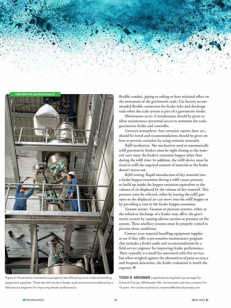
Figure 4. Preventative-maintenance programs are offered by some material-handling
equipment suppliers. These should include a feeder audit and recommendations by a
field-service engineer for improving feeder performance.
PreVenTIVe MaInTenanCe

2020
COME SEE US AT THE PTXI SHOW - BOOTH #: 2515May 6-8, 2014 - Rosemont, IL - Donald E. Stephens Convention Center
2121
Protect against Combustible Dust explosionEconomical approaches exist to protect spray dryer processes and solutions
By Dr. Johannes Lottermann, REMBE
MuCH Has been written and will continue to be written about the risks of combustible dust in a manufacturing facility, if for no other reason, than because people are injured and die every year from combustible dust-related explosions.1
From a manufacturer’s perspective, the costs involved in not protecting a facility are prohibitive: should an incident oc-cur, an operation may be out of business for weeks or months and its customers will go elsewhere. The community outcry will be enormous and damage to an organization’s reputation will result. The costs for startup, fines, compensation to the injured, etc. are very high. It just isn’t worth the risk.2
Unfortunately, the costs of protecting a facility also can be very high, so every manufacturing facility must work closely with its “consultants” — manufacturers’ representa-tives, engineers, risk consultants, insurance consultants and others — to develop the best, most cost-effective working solution for their particular manufacturing process. There-fore, plant process hazard analyses and dust testing should be an integral part of the total safety concept per NFPA standards, OSHA requirements and as a practical matter. 3
One process that has received limited attention with respect to protection against combustible dust risks to date is the spray drying process. The risks are great as are the potential costs for protection following conventional design standards.
New basic interpretations, however, in accordance with the VDI 2263 Data Sheet 7 guideline, “Dust Fires and Dust Explosions for spray dryers — Hazards, Assessment and Protective Measures,” have recently been released which specifically address fire and explosion protection in spray-drying facilities.4,5 These interpretations will be discussed as an alternative cost-effective method of protecting spray dryer processes as they specify the partial volume approach
for the sizing of explosion relief devices described in NFPA 68 and FM Global Loss Prevention Data Sheet 7-76.
Adopting this method should be discussed in detail with Authorities Having Jurisdiction (AHJ) in the interest of im-proved compliance leading to increased safety in addressing the combustible dust hazard.
CoMbusTIble DusT
Any airborne organic dust that can burn could lead to an explosive atmosphere.6 If there is a combination of such dusts with a sufficient ignition source, explosions can occur. OSHA requires in its general duty clause that employers provide a “...place of employment which are free from rec-ognized hazards...” 7, so measures must be taken to avoid or reduce the damage caused by such explosions.
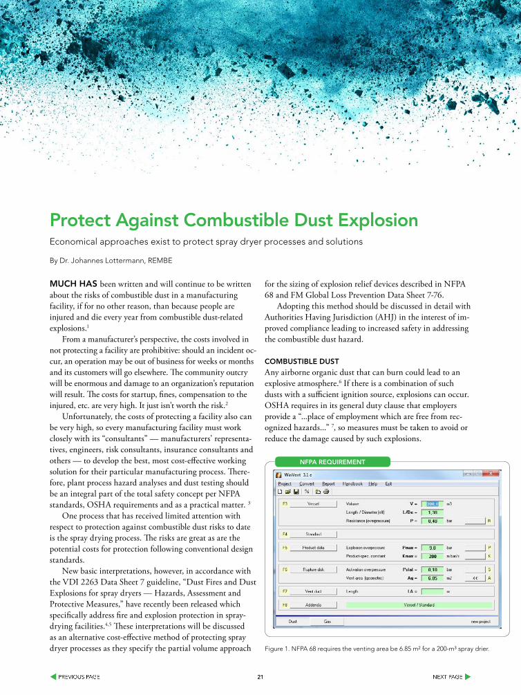
Figure 1. NFPA 68 requires the venting area be 6.85 m² for a 200-m³ spray drier.
nfPa requIreMenT
2222
The risk of combustible dust explosions often is under-estimated: For example, we use powdered milk in food we eat and handle such powder in our kitchens, living rooms, coffee shops and even airplanes. When stored at home in small amounts or even in big bags at warehouses, milk pow-der is considered a harmless product — as long as fine dust particles are not airborne, dispersed and in contact with a source of ignition such as a mechanically created spark, a spark created by discharging static electricity, a hot surface or an open fire.
As a “Checklist for an Explosion,” the following ele-ments have to be in place to create an explosion:
• combustible dust, • a confined area, • oxygen, • an ignition source, and• perfect dispersion of dust particles.
CoMbusTIble DusT rIsKs
In THe sPraY DrYInG ProCess
Spray dryers are primarily deployed in the chemical and food industry, for processes such as powdered milk, deter-gent powder or infant formula production. The liquids (slur-ries) are atomized in a drying tower by means of pressure nozzles or rotating discs. The powdery commodity is dried through hot current or counter-current gas.5
These processes are extremely explosive, as all above mentioned “elements” for a dust explosion are “naturally” in place:5,6
• combustible dust -> the dried product• a confined area -> the drying chamber• oxygen -> by the warm air• an ignition source -> embers, mechanically sparks
created by broken atomizing discs etc.• perfect dispersion of dust particles -> the drying
process requires a dispersion Unfortunately, these conditions are present in other
elements of typical spray-drying installations (cyclones, bag
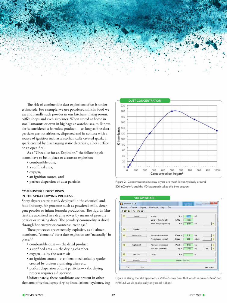
Figure 2. Concentrations in spray dryers are much lower, typically around
500–600 g/m³, and the VDI approach takes this into account.
DusT ConCenTraTIon
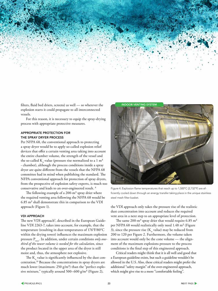
Figure 3. Using the VDI approach, a 200 m³ spray drier that would require 6.85 m² per
NFPA 68 would realistically only need 1.48 m².
VDI aPProaCH
2323
filters, fluid bed driers, screens) as well — so wherever the explosion starts it could propagate to all interconnected vessels.
For this reason, it is necessary to equip the spray-drying process with appropriate protective measures.
aPProPrIaTe ProTeCTIon for
THe sPraY DrYer ProCess
Per NFPA 68, the conventional approach to protecting a spray dryer would be to apply so-called explosion relief devices that offer a certain venting area taking into account the entire chamber volume, the strength of the vessel and the so-called Kst-value (pressure rise normalized to a 1 m³ - chamber), although the process conditions inside a spray dryer are quite different from the vessels that the NFPA 68 committee had in mind when publishing the standard. The NFPA conventional approach for protection of spray dryers, from the prospective of explosion safety experts, is much too conservative and leads to an over-engineered result. 8
The following example of a 200-m³ spray drier where the required venting area following the NFPA 68 would be 6.85 m² shall demonstrate this in comparison to the VDI approach (Figure 1).
VDI aPProaCH
The new VDI approach9, described in the European Guide-line VDI 2263-7, takes into account, for example, that the temperature (resulting in dust temperatures of 176°F/80°C within the drying tower) influences the maximum explosion pressure Pmax. In addition, under certain conditions only one-third of the tower volume is needed for the calculation, since the product located in the upper area of the dryer is still moist and, thus, the atmosphere not explosive.
The Kst value is significantly influenced by the dust con-centration.10 Because the concentrations in spray dryers are much lower (maximum: 250 g/m³) than the “perfect explo-sive mixture,” typically around 500–600 g/m³ (Figure 2),
the VDI approach only takes the pressure rise of the realistic dust concentration into account and reduces the required vent area in a next step to an appropriate level of protection.
The same 200-m³ spray drier that would require 6.85 m² per NFPA 68 would realistically only need 1.48 m² (Figure 3), since the pressure rise (Kst value) may be reduced from 200 to 120 per Figure 2. Furthermore, the volume taken into account would only be the cone volume — the align-ment of the maximum explosions pressure to the process conditions is the final step of this engineered approach.
Critical readers might think that it is all well and good that a European guideline exists, but such a guideline wouldn’t be allowed in the U.S. Also, these critical readers might prefer the additional “safety margin” of the over-engineered approach, which might give rise to a more “comfortable feeling”.
Figure 4. Explosion flame temperatures that reach up to 1,500°C (2,732°F) are ef-
ficiently cooled down through an energy transfer taking place in the unique stainless
steel mesh filter basket.
InDoor VenTInG sYsTeM
2424
These same readers should know that NFPA always gives a performance-based design option as an alternative, which simply means that other approaches also are al-lowed. And, let’s remember, purchasers also have the right to have a “comfortable feeling” that will result in improved compliance with regard to the non-specific partial volume approach. This innovative calculation method allows for effective explosion protection with venting at an affordable, competitive price. Since most spray-dryer installations are indoors, indoor flameless venting is worth consideration.
InDoor flaMeless exPlosIon VenTInG
With indoor venting systems, such as the REMBE Q-Rohr-311,
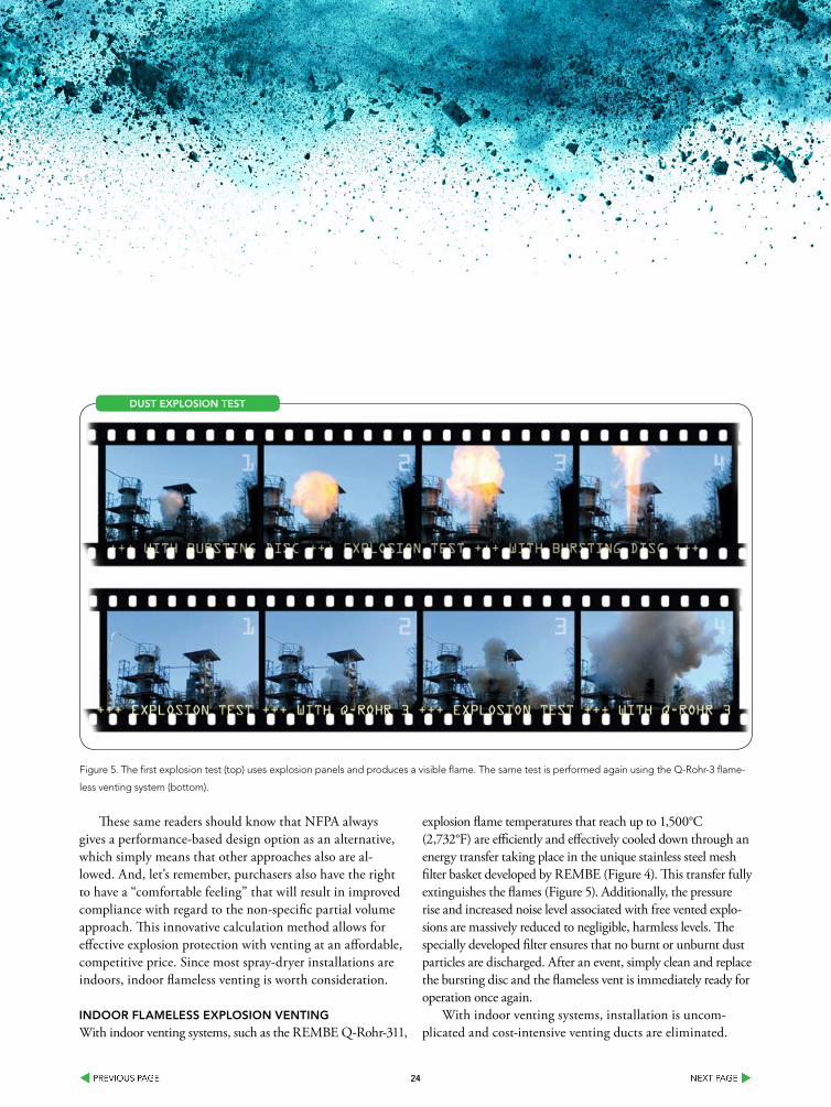
explosion flame temperatures that reach up to 1,500°C (2,732°F) are efficiently and effectively cooled down through an energy transfer taking place in the unique stainless steel mesh filter basket developed by REMBE (Figure 4). This transfer fully extinguishes the flames (Figure 5). Additionally, the pressure rise and increased noise level associated with free vented explo-sions are massively reduced to negligible, harmless levels. The specially developed filter ensures that no burnt or unburnt dust particles are discharged. After an event, simply clean and replace the bursting disc and the flameless vent is immediately ready for operation once again.
With indoor venting systems, installation is uncom-plicated and cost-intensive venting ducts are eliminated.
Figure 5. The first explosion test (top) uses explosion panels and produces a visible flame. The same test is performed again using the Q-Rohr-3 flame-
less venting system (bottom).
DusT exPlosIon TesT
2525
Procedure-optimized installation within the immediate vicinity of people and machines also is an advantage, as is visual inspection without high-priced maintenance costs. All of these features add up to additional savings.
realIsTIC CoMbusTIble DusT exPlosIon ProTeCTIon
A modern explosion protection system must be safe and economically reasonable. In this way, the level of protection, and thus occupational safety, is ensured.
The VDI approach for protecting spray dryers is just one
example of a method to potentially reduce an operator’s cost to protect. Realistically evaluating risks is another approach that may result in less equipment or less costly equipment being used. Whatever the approach, spray dryer processes must be evaluated for their combustible dust risk and pro-tected accordingly.
Dr. JoHannes loTTerMann is senior consultant explosion
protection; head of Projects and Expansion department, REMBE GmbH,
Brilon, Germany. He can be reached at [email protected].
referenCes1. incidence numbers vary and the near misses are not accounted for. see, for example: peetz, Ben, cFps, combus-
tibleDust Fires and explosions, www.fireengineering.com/articles/print/volume-165/issue-3/features/combustible-dust-fires-and-explosions.html “according to osha, since 1980, almost 150 workers have been killed and more than 850 injured in combustible dust explosions.
2. see, for example, Febo, Jr, henry, processes for Drying powders – hazards and solutions www.aidic.it/lp2013/webpapers/15febo.pdf
3. osha on combustible Dust: www.osha.gov/publications/3371combustible-dust.html; every NFpa standard relating to combustible dust. NFpa: see, for example, NFpa 69, 2014 section 4.2.3.
4. european Guideline VDi 2263-7, Dust Fires and Dust explosions-hazards, evaluation and protection measures, 3/2013.
5. Febo, Jr, henry, processes for Drying powders – hazards and solutions www.aidic.it/lp2013/webpapers/15febo.pdf p.46. For more information on combustible dust, see, mayer, Gerd, ph.D, mitigate explosions with indoor Flameless Vent-
ing, chemical processing e-handbook 1302 v2 page 24: www.chemicalprocessing.com/assets/wp_downloads/pdf/powder-ehandbook-1302-v2.pdf
7. osha General Duty clause: www.osha.gov/pls/oshaweb/owadisp.show_document?p_id=3359&p_table=oshact8. Febo, Jr, henry, processes for Drying powders – hazards and solutions www.aidic.it/lp2013/webpapers/15febo.pdf
p.5 . NFpa 68 standard on explosion protection by Deflagration Venting, 20139. see also, Febo, Jr, henry, processes for Drying powders – hazards and solutions www.aidic.it/lp2013/
webpapers/15febo.pdf p.5 . NFpa 68 standard on explosion protection by Deflagration Venting, 201310. combustible Dust defined: www.osha.gov/publications/3371combustible-dust.html; Vahid ebidat, ph.D, Dust ex-
plosion hazard assessment, 2009 presentation: www.aiha.org/Localsections/html/metro%20NY/combustible%20Dust%20-%20Dr.%20ebadat,%20chilworth.pdf
11. the Q-rohr-3 indoor explosion venting system is licensed/compliant with all currently relevant guidelines, e.g. NFpa 68, VDi 3673, eN 16009 or eN 14797. For more information see www.rembe.us/products/explosion-protection/indoor-outdoor-flameless-venting-systems/