


Make Solids Problems Take a Powder - Chemical … than 60 years of custom application experience....
31
POWDER eHANDBOOK Make Solids Problems Take a Powder
Transcript of Make Solids Problems Take a Powder - Chemical … than 60 years of custom application experience....

POWDER eHANDBOOK
Make Solids Problems Take
a Powder

PNEUMATIC CONVEYING COMPONENTS & SYSTEMS • BULK BAG LOADING & UNLOADING SYSTEMSBAG DUMP STATIONS • FLEXIBLE SCREW CONVEYORS • AERO-MECHANICAL CONVEYORS
MULTI-INGREDIENT HANDLING SYSTEMS • BATCH WEIGHING & SCALING SYSTEMSUL-CONTROLS & CONTROL PACKAGES • MOBILE VACUUM CONVEYING SYSTEMS
Let us solve your pneumatic conveying challenges. Visit vac-u-max.com/pneumatic or call 800-VAC-U-MAX.
More than 60 years of custom application experience.
Over 10,000 different powder and bulk materials
handled. Technical expertise in food, pharma,
chemicals, plastics and more. And an airtight
performance guarantee. It’s what makes VAC-U-MAX
as unique and trusted as the pneumatic conveying
solutions we design.
From components to fully-automated systems, we create bulk material handling solutions entirely around your processing needs and goals.
Custom Solutions. GuaranteedPerformance.
VAC-U-MAX Filter Separator and Bulk Bag Loader for Carbon Black
VAC3509 Product 7x10 PCG2-USA.indd 1 11/21/2016 12:19:22 PM

POWDER eHANDBOOK: Make Solids Problems Take A Powder 3
TABLE OF CONTENTSTalk to a Chemist 7You may get valuable insights for successfully scaling up a process Surmount Sticky Situations 11A properly designed fluid-bed dryer can handle sticky solids
Support Good Housekeeping Practices 15Implement a proactive approach using industrial vacuum cleaners to prevent secondary dust explosions
Predicting Powder Flow Behavior Just Got Easier 22New shear cell tests help to ensure product consistency
Understand Powder Flow Characteristics 28A powder’s variables and external factors will greatly impact blender size
The REMBE Q-Rohr-3 family of products is an indoor flame-
less venting system that eliminates the need for relocating dust
collectors or other enclosures outside. The REMBE Q-Rohr-3
consists of a specialized stainless steel mesh construction and
a REMBE rupture disc. An integrated signaling unit connects to
any audible/visual alarm and shutdown to alert plant personnel,
should there be an incident. In an event, flames are extinguished,
pressure, noise and dust are reduced to negligible levels. The
system is FM and ATEX approved and NFPA compliant.
The product line is now approved for use with dusts, gases, hy-
brid mixtures and metal dusts. The Q-Rohr-3-6T and Q-Rohr-3-6T-AL are ideal for applications
found in pharmaceutical, coatings, steel, iron and other industries. Click here for more info.For over 40 years, REMBE, GMBH has been and continues to be a leader in the innovation
and manufacture of high-quality explosion protection systems. As the inventor of flameless
venting, REMBE, specializes in combustible dust explosion prevention/protection systems
for many applications across a multitude of industries. To download our free case study guide, click here.
INDOOR VENTING HELPS MANAGE COMBUSTIBLE DUST EXPLOSION RISKS
P R O D U C T F O C U S
REMBE, INC. | 855-821-6230 | www.rembe.us
www.chemicalprocessing.com

Federal Equipment Company has a large inventory of
reliable chemical processing equipment from reputable
sources on-hand to meet your needs at any time. We
obtain much of our inventory by providing asset manage-
ment services to many large, multinational corporations.
This gives you a wide range of options to get the leading
OEM brand equipment you need installed economically.
No matter what your equipment needs are, make Federal
Equipment your first call.
THINI EQUIPMENTSAVINGS
+1 877 536 1509 > www.fedequip.com
When you think equipment, think Federal Equipment

POWDER eHANDBOOK: Make Solids Problems Take A Powder 5
AD INDEXAMETEK Brookfield • www.brookfieldengineering.com . . . . . . . . . . . . . . . . . . . . . . . . . . . . . . . . . . . . . . . . . . .10
Federal Equipment Company • http://fedequip.com/ . . . . . . . . . . . . . . . . . . . . . . . . . . . . . . . . . . . . . . . . . . . . . 4
Kuriyama of America, Inc. • www.kuriyama.com . . . . . . . . . . . . . . . . . . . . . . . . . . . . . . . . . . . . . . . . . . . . . . . 8, 14
NETZSCH Premier Technologies, LLC • www.netzsch.com/gd . . . . . . . . . . . . . . . . . . . . . . . . . . . . . . . . . . 5, 27
Rembe Inc. • www.rembe.us . . . . . . . . . . . . . . . . . . . . . . . . . . . . . . . . . . . . . . . . . . . . . . . . . . . . . . . . . . . . . . . . . .3, 21
Schenck Process • www.schenckprocess.com . . . . . . . . . . . . . . . . . . . . . . . . . . . . . . . . . . . . . . . . . . . . . . . . . .6, 12
Vac-U-Max • www.vac-u-max.com/pneumatic . . . . . . . . . . . . . . . . . . . . . . . . . . . . . . . . . . . . . . . . . . . . . . . . . . . . .2
The Condux multi–system tool combines all of
the advantages of modern grinding technol-
ogy with a multitude of application possibilities.
Equipped with various grinding tools and sta-
tors, the machine is suited for a large range of
products. High-performance rotors are used in
combination with various stator baskets for high
operational demands. With an integrated dy-
namic air classifier, higher finenesses, down to
less than 30 micron, can be achieved with ease.
Unlike conventional classifier mills, the grinding disc and classifier wheel are torque proof
connected and are driven by a single motor. Adjustment to the grinding fineness is conducted
by adjusting the speed of the grinding disc/classifier combination, and can also be done by
changing the height of the classifier wheel. The air volume flow can also be adjusted through
similar actions.
IMPACT MILL SUPPORTS PRODUCT CHANGES
P R O D U C T F O C U S
NETZSCH | 610-363-8010 | http://pumps.netzsch.com
www.chemicalprocessing.com
One source for all your needs
Integrated Bulk Material Handling Systems
Our knowledge and manufacturing expertise in weighing, feeding, pneumatic conveying and filtration provide customers a single source for meeting their critical bulk material handling and dust collection needs. As a global company, our resources stretch throughout the world enabling us to provide you the ideal system through the utilization of core capabilities and services which include:
• Project Management • Systems Engineering• Service & Spare Parts • Installation & Start-Up• Local Manufacturing • Test Centers
For more information on how we can put an integrated bulk material handling system together for you, please contact us.
Weighing
Feeding
Pneumatic Conveying
Filtration
Schenck ProcessKansas City, [email protected]

POWDER eHANDBOOK: Make Solids Problems Take A Powder 7
www.chemicalprocessing.com
Chemical engineering is the art of
producing a material economi-
cally. That last word distinguishes
us from chemists. Now don’t get me wrong,
chemists come up with innovations and
sometimes can offer great ideas on how to
improve a process. For instance, when it
comes to crystallization, their ability to opti-
mize the crystallization and make a product
with few impurities gives us a clear goal and
helps define what can be manufactured on
a larger scale.
Unfortunately, the steps taken by the chem-
ist may require more time, induce product
changes and involve much more expensive
equipment than the product’s profit margin
can justify for commercial production. Also,
scale-up may result in a different physical or
chemical form. We can’t build a plant based
on hundreds of Buchner funnels and being
close to the Hoover Dam to run a filtration
process. However, working with the chem-
ist to identify the physical properties and
extrinsic conditions that control the various
steps in the process can convert the labo-
ratory findings into a meaningful process
design. Dozens of examples cross my mind,
but the following illustrates how talking to
the chemist can result in a practical and
economical design.
Our laboratory had developed a new chemi-
cal for use in a consumer product. The
chemists could grow the product to as large
as 500 micron — but this could take 20–30
hours. In about 6–8 hours, they could get
to about 100 micron. We expected some
attrition in the real world and the crystal-
lizer would utilize the fine particles. How-
Talk to a ChemistYou may get valuable insights for successfully scaling up a process
By Tom Blackwood, Contributing Editor
www.chemicalprocessing.com
POWDER eHANDBOOK: Make Solids Problems Take A Powder 8
ever, our customer wouldn’t tolerate the
amount of dust created during drying and
post-drying handling. (That firm was sensi-
tive to having any dusty material handled
by consumers.) Fortunately, we looked into
this product’s physical properties, such as
clumping, flowability and agglomeration.
During this evaluation, we discovered the
material clumps easily. Normally, this would
be taken as a negative for most final prod-
ucts but we turned it into an advantage.
After a few more discussions and experi-
ments by our chemists, we looked at four
alternative routes:
1. Crystallize to 50 micron, filter and wash
to remove impurities, and then extrude to
200 micron. Drying produced very little
dust.
2. Feed the wet cake from the previous
route into a granulating fluid-bed dryer to
get a 100-micron particle with a slightly
wider particle size distribution (PSD).
3. Dry the wet cake in a flash dryer and then
spheronize the fine particles to about 100
micron in a tilted-pan dryer with water
added back to agglomerate the particles.
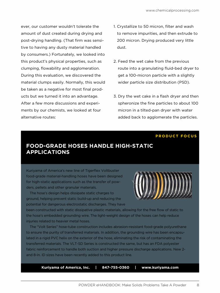
Kuriyama of America’s new line of Tigerflex Voltbuster
food-grade material-handling hoses have been designed
for high-static applications such as the transfer of pow-
ders, pellets and other granular materials.
The hose’s design helps dissipate static charges to
ground, helping prevent static build-up and reducing the
potential for dangerous electrostatic discharges. They have
been constructed with static dissipative plastic materials, allowing for the free flow of static to
the hose’s embedded grounding wire. The light-weight design of the hoses can help reduce
injuries related to heavier metal hoses.
The “Volt Series” hose-tube construction includes abrasion-resistant food-grade polyurethane
to ensure the purity of transferred materials. In addition, the grounding wire has been encapsu-
lated in a rigid PVC helix on the exterior of the hose, eliminating the risk of contaminating the
transferred materials. The VLT-SD Series is constructed the same, but has an FDA polyester
fabric reinforcement to handle both suction and higher pressure discharge applications. New 2-
and 8-in. ID sizes have been recently added to this product line.
FOOD-GRADE HOSES HANDLE HIGH-STATIC APPLICATIONS
P R O D U C T F O C U S
Kuriyama of America, Inc. | 847-755-0360 | www.kuriyama.com
www.chemicalprocessing.com
POWDER eHANDBOOK: Make Solids Problems Take A Powder 9
4. Crystallize to 100 micron, filter, wash and
dry as originally planned, but use the
fines from downstream processing as
seeds for the crystallizer. This reduced
the crystallization time to less than 2
hours.
With these routes defined, we could
evaluate the unit operations, which also
allowed us to supply product samples to
our customer, and price the project. This
provided confidence that full-scale opera-
tions would meet the customer’s long-
term goals.
Always remember there’s no universal for-
mula for the best solids route like there is
for liquid processes. Moreover, as the above
example highlights, finding the most eco-
nomical solution often depends upon evalu-
ation of physical properties.
With solids processing, you must perform
several crucial steps for the scale-up and
design of any new process and before
significantly modifying an established one.
The first is to establish the basic process
route and evaluate alternatives as illustrat-
ed above. Next, you must define required
product properties such as PSD, stickiness,
flowability, dustiness and ease of solubil-
ity. Ignoring that latter point has caused
grief many times when making a “minor”
process change. Basic filtration and dry-
ing data often are overlooked as product
properties; this can lead to a lot of extra
work in assessing the various dryer choic-
es. Obtaining single-particle drying kinetics
and using models to evaluate a wide range
of dryers can simplify the selection.
Another often-overlooked factor in the
planning of experiments with solids is
temperature sensitivity, especially for
polymorphs. This is an area in which chem-
ists shine because they have the tools to
identify polymorphs and solvates. With
molecular models available, they can pro-
pose and later validate these chemicals.
TOM BLACKWOOD is a Chemical Processing contributing
editor. You can email him at [email protected]

POWDER eHANDBOOK: Make Solids Problems Take A Powder 11
“Don’t put them in a fluid bed.”
I often hear this comment
about sticky solids from plant
operators and engineers because they’ve
had many bad experiences with fluid beds.
They end up spending countless hours
cleaning out a plugged distributor, opening
a discharge chute or banging on the vessel
to get the solids to flow. They say the solids
are too sticky to fluidize. Let’s face it: sticky
solids need special attention. But first, we
must identify the source of the stickiness.
Almost all fine solids, when wet, are sticky.
Many others clump due to a variety of fac-
tors including stickiness (see: “Clamp Down
on Clumping,” http://goo.gl/bxhldn). Only
a few of those factors come into play in the
operation of a fluid bed; the leading issue is
the solvent, usually water. In my mind, melt-
ing of the particulate solids is the only le-
gitimate excuse for plugging a fluid bed. So,
what are the real causes of pluggage and
how can you prevent them? The problem
mainly arises on the fluidizing plate, screen
or grid. The failure often stems from poor
dispersion of the solids, lack of enough bed
depth, low velocity through the grid and
spacing the holes in the grid too far apart,
as the following examples show:
• In one dryer project, a centrifuge had
been placed above the dryer to eliminate
the need for a screw feeder. Unfortunate-
ly, if the centrifuge was over-fed, slurry
dropped onto the dryer grid. The grid had
tuyeres designed for a catalytic cracker
instead of a dryer. These were replaced
with a more-robust design while retaining
the tuyere spacing. The increase in veloc-
Surmount Sticky SituationsA properly designed fluid-bed dryer can handle sticky solids
By Tom Blackwood, Contributing Editor
www.chemicalprocessing.com

www.chemicalprocessing.com
POWDER eHANDBOOK: Make Solids Problems Take A Powder 12
ity and horizontal gas flow tolerated the
occasional centrifuge upsets, which were
reduced by better instrumentation. The
benefits of the new grid design didn’t stop
there. The dryer product had a more-uni-
form moisture content, partially due to the
greater heat transfer to the solids. Later,
thanks to the change in grid design, the
plant was able to raise the capacity of the
dryer.
• On a second project, the plant engineers
were painfully aware of the stickiness of
their product; it plugged up the centri-
fuge discharge on a regular basis. Also,
the moisture content was higher than
normally encountered in a fluid bed. The
solution was to install a high-speed mill
above the dryer even though the solids
already were finer than the mill could
produce. It dispersed the solids over the
bed without attriting the particles. The
fluid bed was split into zones, with the
first very deep. This design allowed the
particles to flash off the free moisture and
eliminate the normally sticky surface. The
deep bed required more pressure drop
across the grid to ensure uniform distribu-
This precision machined valve is designed to prevent contamina-
tion and provide line switching for either dilute or dense phase
conveying. The two-way PT45 valve operates as a 1-to-2-way
diverting valve or a 2-to-1-way converging valve in a pneumatic
conveying system for powdered or granular materials.
The PT45’s actuator rotates the tunnel forward and back-
wards in the housing. This positions the tunnel to either the
divert ports or the straight-through ports. Shaft bearings sup-
port the tunnel in the two end plates and between two thrust
washers. The tunnel has position stops located in the housing
for fine adjustment of both conveying positions. To prevent
contamination, the tunnel rotates 45° port to port.
Two proximity switches mounted in the housing, sensing directly off of the tunnel, in-
dicate tunnel position. A positive seal is made through the selected position between the
tunnel bore and the housing interior by seal rings. During tunnel position changes, the seal
rings act like a wiper to clean the surface of the tunnel.
It can operate at conveying line pressures up to 110 psi. The aluminum housing and tunnel
are hard anodized for wear resistance.
PARALLEL TUNNEL DIVERTER VALVE MINIMIZES CONTAMINATION
P R O D U C T F O C U S
Schenck Process | 816-891-9300 | http://goo.gl/cqHYIy
www.chemicalprocessing.com
POWDER eHANDBOOK: Make Solids Problems Take A Powder 13
tion of the solids and to keep them off the
grid. In addition, the higher pressure-drop
requirement called for smaller grid holes
that were spaced closer together to avoid
hot spots.
• Another project involved a dryer suffer-
ing excessive entrainment after a recent
product change presented a finer mate-
rial to it. The corporate health and safety
group had mandated a minimum veloc-
ity through the fluid bed of 3 ft/s for this
product — due to frequent fires in the
dryer when the velocity was below 3 ft/s,
even though the solids could be fluidized
easily at 1 ft/s. I replaced the grid with
one that had the same pressure drop at 1
ft/s as the old one had at 3 ft/s. The lower
velocity in the bed reduced the entrain-
ment while the higher velocity through
the grid kept the solids from sticking to
the grid and burning. It also improved
the heat transfer and evaporation rate,
enabling the dryer to maintain the same
production rate despite the lower fluidiza-
tion velocity.
The secret to putting particulate solids into
a fluid bed successfully (which means
getting them out in one piece) is close
attention to dispersion of the solids, good
bed depth, and careful design of the fluidi-
zation grid. It’s amazing how many other
good things happen when you properly put
sticky solids into a fluidized bed.
TOM BLACKWOOD is a Chemical Processing contributing
editor. You can email him at [email protected]
ALL TIGERFLEX™ AND KURI TEC® FOOD GRADE HOSES ARE NOW
PHTHALATE FREE!What does this mean?
Tigerflex™ and Kuri Tec® food grade hoses are now manufactured from all phthalate free materials. As a leading manufacturer of hoses for the food & pharmaceutical industries, our food grade hoses have always used extremely high purity PVC materials, meeting various FDA, NSF, USDA and 3A standards. The hoses will still maintain all their previous standards, but with the added benefit of now being phthalate free at no additional cost.
Why did we do it?
Due to the growing desire in the food processing and pharmaceutical industries to use products that do not contain phthalates, we’ve taken the industry leading posi-tion of eliminating them from our entire line of food grade Tigerflex™ and Kuri Tec® products. As always, we strive to provide our customers with the highest purity products as you’ve come to expect from Kuriyama.
Headquarters, Sales Office and Warehouse Location360 E. State Parkway, Schaumburg, IL 60173-5335
Phone: (847) 755-0360 • Toll-free FAX: (800) 800-0320International FAX: (847) 885-0996
Web Site: http://www.kuriyama.com E-Mail: [email protected]

www.chemicalprocessing.com
POWDER eHANDBOOK: Make Solids Problems Take A Powder 15
Since the U.S. Chemical Safety Board
(CSB) released its 2006 Combustible
Dust Hazard Study, the U.S. Occu-
pational Safety and Health Administration
(OSHA) has continued to amend its General
Industry Housekeeping standards. Changes
to the housekeeping requirements came as
a result of employers’ misinterpretation of
housekeeping standards already included in
the provision, and workplace accidents that
occurred due to combustible dust explosions.
The General Industry Housekeeping stan-
dard applies to accumulations of dust that
contribute to an explosion hazard. Provi-
sion 1910.22 aims to eliminate any doubt
that employers are obligated to prevent
combustible dust from accumulating in their
workplaces.
Although OSHA’s General Industry House-
keeping provision 1910.22 doesn’t specifi-
cally address housekeeping and fugitive
dust, other OSHA standards do address
fugitive dust and suggest that operations
“eliminate the use of compressed air jets to
clean accumulated dust from the equipment
or clothing and substitute a vacuum clean-
ing system” and “use a vacuum cleaning
system to clean spills and dust accumula-
tions. Avoid brooms and shovels.”
However, there is still more regulation
needed regarding the handling of fugitive
dust for general industry, including food
products, rubbers, metal, wood, pharma-
ceuticals, plastics, paint and coatings and
synthetic organic chemicals.
Support Good Housekeeping PracticesImplement a proactive approach using industrial vacuum cleaners to prevent secondary dust explosions
By David Kennedy, Vac-U-Max

www.chemicalprocessing.com
POWDER eHANDBOOK: Make Solids Problems Take A Powder 16
FIRST DEFENSE: CONTROL FUGITIVE DUSTIn nearly all industries, with the exception of
the metals industry, the National Fire Pro-
tection Association (NFPA) recommends
vacuum cleaning as the preferred first-
defense method of controlling fugitive dust.
NFPA 654 states that “vigorous sweeping
or blowing down with steam or compressed
air produces dust clouds.” Specifics on
NFPA standards in relation to particular
industries will be covered later.
Despite the recommendations of NFPA
and OSHA standards, many companies
still use air compressors and brooms to
clean surrounding equipment and areas of
dust and debris. This may be due to the
misconception about industrial vacuum
cleaners and sheer oversight when review-
ing production processes. When a process
has been in place for decades, it becomes
somewhat transparent, and the standard
reasoning that “if it ain’t broke, don’t fix it”
often prevails.
The problem with using brooms and air
compressors is that they just blow the dust
around, resulting in small particles that
settle onto elevated surfaces.
In an effort to bring a greater awareness to
the severity of poor housekeeping methods,
OSHA launched a National Emphasis Pro-
gram (NEP) focusing on workplaces where
combustible dust hazards are likely to be
found and lists different types of materials
that can generate combustible dust.
Industries covered by the NEP include agri-
culture, food processing (including sugar),
chemicals, textiles, forest products, metal
processing, tire and rubber manufacturing,
paper products, pharmaceuticals, recycling
operations and coal handling and process-
ing facilities.
These industries deal with a wide range of
combustible dusts with differing properties,
including metal dusts such as aluminum and
magnesium, wood dust, coal and carbon
dust, plastic dusts, biosolids, certain textile
materials and organic dusts such as paper,
soap, dried blood and sugar.
VITAL HOUSEKEEPING STANDARDS While many technological advances have
come about over the past 50 years to pre-
vent dust explosions, good housekeeping is
vital. OSHA notes that without the accumu-
lation of significant amounts of combustible
dust, catastrophic secondary explosions will
not occur.
Even with OSHA’s increased enforcement,
NFPA standards and the CSB’s push for
tougher adherence, dust fires and explo-
sions continue to happen” In 2012, the
CSB estimated that a percentage of those
explosions could have been prevented if
there were standard housekeeping prac-
tices in place”

www.chemicalprocessing.com
POWDER eHANDBOOK: Make Solids Problems Take A Powder 17
After the Port Wentworth, Georgia-based
Imperial Sugar refinery dust explosion in
2008, OSHA launched an intense campaign
targeted at preventing additional mishaps
and disbributed a fact sheet, HazardAlert:
Combustible Dust Explosions, that addresses
secondary explosions.
It states that “due to poor housekeeping
practices, an initial explosion may dislodge
into the air the dust that is accumulated on
the floors, beams, and other areas of a work-
place. This dispersed dust, if ignited, may
cause one or more secondary explosions.
These secondary dust explosions can be far
more destructive than a primary explosion
due to the increased quantity and concen-
tration of dispersed combustible dust. Many
deaths in past accidents, as well as other
damage, have been caused by secondary
explosions.”
The alert also references several NFPA stan-
dards that address the need for companies to
use vacuum cleaners in housekeeping prac-
tices to prevent catastrophic explosions.
Addressing the need for to comply with
housekeeping requirements, Edwin G. Foulke,
Jr., then Assistant Secretary of OSHA noted
“The fatalities and injuries at the Port Wen-
tworth sugar refinery probably could have
been prevented had Imperial Sugar complied
with existing OSHA standards on housekeep-
ing and other OSHA requirements.”
After the explosion, the company willfully
refused to remedy similar conditions at its
Gramercy, Louisiana plant, which has since
closed, resulting in more than $8.7 million of
proposed penalties for both plants, the third
highest proposed penalty in OSHA’s history.
The relative cost of even the most elaborate
central vacuum system is minute compared
to the loss of life that occurs from second-
ary explosions or the fines levied against a
company that fails to proactively protect
their workers.
INDUSTRIAL VACUUM CLEANER INSTALLATION
Figure 1: Installing industrial vacuum clean-ers can result in additional benefits in the areas of production, reclamation or wage savings.
www.chemicalprocessing.com
POWDER eHANDBOOK: Make Solids Problems Take A Powder 18
Although the majority of companies aren’t
in willful violation of the standards, a lack
of understanding of housekeeping stan-
dards and misconception of the relatively
low cost of vacuum systems prevail in the
industry. Often times, the addition of indus-
trial vacuum cleaners to the housekeeping
routine produces cost benefits in terms of
increased production, reclamation or wage
savings (Figure 1).
APPLYING HOUSEKEEPING STANDARDS Although using vacuums isn’t new to the
many industries, some companies have
tried in the past to use shop-type vacuums
to clean up dust and debris and have found
them inadequate under the rigorous de-
mands in the processing industry.
In contrast to shop-type vacuums, industrial
vacuums can suck up tons of material an
hour. One such industrial vacuum is the air-
operated vacuum cleaner, or air vac. Frank
Pendleton co-founder of Vac-U-Max, Bel-
leville, New Jersey, introduced it in 1959 to
prevent dust explosions in textile mills.
The proper selection of an industrial vacuum
cleaning system is based primarily on the ap-
plication. In some cases small air- and elec-
tric-powered drum-style units will suffice,
while others require central large electric-
and diesel-powered units for multiple users
and filtration systems capable of capturing
particles that are invisible to the naked eye.
Some applications require customized vac-
uum cleaner installations. For other applica-
tions, compact, off-the-shelf vacuum sys-
tems are perfectly adequate when replacing
crude or unnecessarily hazardous cleaning
methods, such as the use of compressed-air
hoses for blowing debris.
Often, users of industrial vacuum cleaning
systems may assume they need a custom,
one-of-a-kind solution when their appli-
cation actually calls for a pre-engineered
product. In other words, most applications
require standard equipment with capabili-
ties to best fit an application.
To prevent combustible dust explosions,
companies can follow NFPA standards and
guidelines when setting up a good house-
keeping program. NFPA standards applica-
ble to dust explosion harzards include 654,
61, 484, 664 and 655. Except for NFPA 61
and 664, which deal with combustible met-
als and food/agriculture products respec-
tively, the fugitive dust control and house-
keeping standards generally are the same
for manufacturing, processing and handling
of combustible particulate solids, wood
processing and woodworking facilities, and
also for sulfur.
In brief, the housekeeping standards call
for establishing regular cleaning frequen-
cies to minimize dust accumulation on
walls, floors and horizontal surfaces such
as equipment ledges, above suspended

www.chemicalprocessing.com
POWDER eHANDBOOK: Make Solids Problems Take A Powder 19
ceilings and other concealed surfaces.
The standards further state that vigorous
sweeping or blowing down with steam
or compressed air should take place only
after the area or equipment has been
vacuumed because of the creation of dust
clouds by the other methods.
Standards also call for vacuum cleaners to
be specified for use in Class II hazardous
locations or for a fixed-pipe suction system
with a remotely located exhauster and dust
collector. When flammable gases are pres-
ent, vacuum cleaners need to be listed for
Class I and Class II hazardous locations.
NFPA 61 for food and agricultural process-
ing plants has somewhat reduced precau-
tions than the previously listed standards,
and NFPA 484 for combustible metals
requires that dust and particles be cleaned
with non-conductive scoops or soft natu-
ral brushes or brooms before the dust is
vacuumed. In addition, vacuums are sug-
gested to pick up dust that is too small to
be picked up with brushes. Blowing com-
bustible metal dust with air compressors is
not permitted.
For cleanup of truly explosive materi-
als such as gunpowder, rocket propellant,
sodium azide, aluminum powder and other
materials that can explode if collected in
dry form, a submerged recovery vacuum
cleaner is available and designed specifi-
cally to pick up explosive powders safely.
The explosive or hazardous material is sub-
merged under fluid to render it inert. The
design includes not only a high-liquid-level
safety shutoff, but also a low-liquid-safety
shutoff to prevent vacuum operation if in-
sufficient liquid is in the drum.
HOUSEKEEPING FOR FINE POW-DERS AND CHEMICALSIndustrial vacuum cleaner experts can
design systems for a company’s particular
needs. For instance, productivity suffered
when a custom job shop fabricator faced
potential flammability issues because it
couldn’t adequately sweep the fine pow-
der coating residue from the floor, lights,
booth walls and components of its shop
and the shop-type vacuums it had been
using posed a static electric shock to the
workers. Not only did workers have to
vacuum, but they also had to clean by
hand using wet rags to prepare booths for
the next powder coating job.
The fabricator sought out Vac-U-Max for a
system that could prevent static. To elimi-
nate any shock, fire or explosion hazard
associated with electric- or engine-driven
units, a Venturi compressed-air-powered
vacuum was installed. Antisparking vac-
uum inlets and grounding lugs, and static
conductivity from end to end, including a
static-conductive hose with internal ground
wire and grounded end cuffs, help prevent
static build up.
www.chemicalprocessing.com
POWDER eHANDBOOK: Make Solids Problems Take A Powder 20
To further reduce sparking danger, static-
conductive filters were used, rated 99.9%
efficient at 1 micron, which virtually elimi-
nated any fine-particle discharge from the
vacuum’s exhaust back into the work area.
This helped to create healthful, productive
breathing conditions in the workplace.
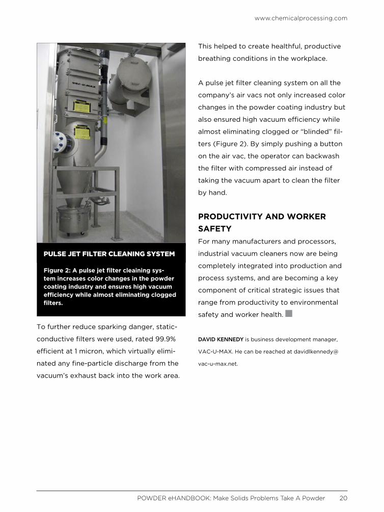
A pulse jet filter cleaning system on all the
company’s air vacs not only increased color
changes in the powder coating industry but
also ensured high vacuum efficiency while
almost eliminating clogged or “blinded” fil-
ters (Figure 2). By simply pushing a button
on the air vac, the operator can backwash
the filter with compressed air instead of
taking the vacuum apart to clean the filter
by hand.
PRODUCTIVITY AND WORKER SAFETYFor many manufacturers and processors,
industrial vacuum cleaners now are being
completely integrated into production and
process systems, and are becoming a key
component of critical strategic issues that
range from productivity to environmental
safety and worker health.
DAVID KENNEDY is business development manager,
VAC-U-MAX. He can be reached at davidlkennedy@
vac-u-max.net.
PULSE JET FILTER CLEANING SYSTEM
Figure 2: A pulse jet filter cleaining sys-tem increases color changes in the powder coating industry and ensures high vacuum efficiency while almost eliminating clogged filters.

Inc.
© REMBE | All rights reserved
Gallbergweg 21 | 59929 Brilon, GermanyT +49 2961 7405-0 | F +49 2961 [email protected] | www.rembe.de
Contact us for Europe Contact us for North America
3809 Beam Road Suite K | Charlotte, NC 28217, USAT +1 704 716 7022 | F +1 704 443 [email protected] | www.rembe.us
GOT COMBUSTIBLE
DUST?Reduce Your RISK!
Call REMBE®.
Protect your manufacturing facility with venting and isolation equipment designed to prevent or minimize the effects of combustible dust explosions.
REMBE® is dedicated to providing you with top-of-the-line recommendations, equipment and service every time!
BY R E M BE®
DEVELOPED IN 1988
Q-Rohr® Q-Box EGVPat.-Nos: DE 38 22 012; US 7,905,244
Li 175x250 Anz ES ENG.indd 1 09.01.15 15:38
Ask any plant manager if there is
a way to know beforehand that
a cohesive powder such as lime-
stone, carbon black or cement will have dis-
charge problems feeding from a bin. Most
will say, there’s a “definite possibility,” but
they may not know the level of difficulty or
when interruptions are likely to occur.
Processing experience makes operations
personnel naturally suspicious of potential
processing problems. If they’ve had issues in
the past, they may anticipate future stop-
pages. However, they need some type of
powder measurement to provide a forewarn-
ing before the start of the production run.
Instruments typically used to assess powder
characteristics — analyzers for particle size,
particle shape, moisture content and electri-
cal charge — do not measure flow behavior.
They are useful in explaining underlying
reasons why a powder potentially will have
flow difficulty, but they don’t provide a use-
ful indicator for flow behavior.
Traditional methods for evaluating pow-
der flow — Flodex cup, angle of repose
and tap test — are not truly relevant,
either. Because they are inexpensive and
quick to perform, they have endured the
test of time for use in powder testing
labs. However, they identify only physical
properties that may correlate with flow
behavior but do not assess flowability in
and of itself.
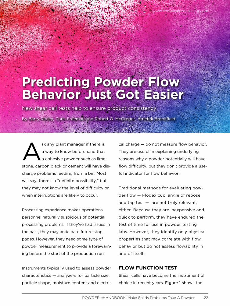
FLOW FUNCTION TESTShear cells have become the instrument of
choice in recent years. Figure 1 shows the
Predicting Powder Flow Behavior Just Got EasierNew shear cell tests help to ensure product consistency
By Barry Ridley, Chris Freeman and Robert G. McGregor, Ametek Brookfield
www.chemicalprocessing.com
POWDER eHANDBOOK: Make Solids Problems Take A Powder 22

basic components of an annular shear cell.
It requires a small powder sample volume
(Figure 1a), uses a vane lid to compress
the particles together (Figure 1b) and then
shears them against one another to quantify
the sliding friction for relative movement
(Figure 1c). The test method is called “flow
function,” and the resulting graphical in-
formation is referred to by the same name.
This basic technical approach was estab-
lished more than 50 years ago in the miner-
als industry.
WALL FRICTION TESTA second test involves use of the wall fric-
tion lid (see Figure 1c again) to measure the
resistance of powder sliding down the hop-
per wall before exiting the bin. This method,
called the wall friction test, is also known as
the “angle of wall friction curve” in graphi-
cal information.
The wall friction lid also is useful for test-
ing powder compressibility, which quanti-
fies how density increases from the initial
“loose-fill” condition in the sample trough
to higher-density values as the lid pushed
down on the sample and compaction pres-
sure increases.
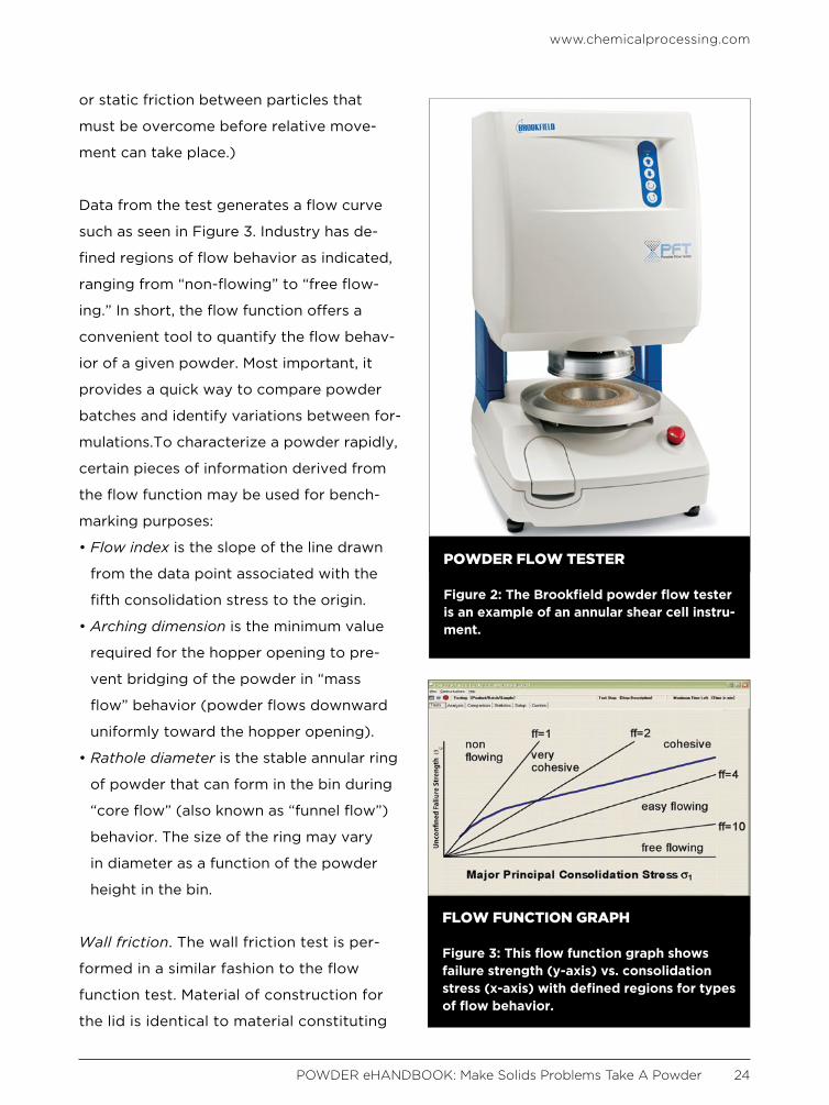
Improvements in instrument design have
led to modern shear cells that are afford-
able and easy to use, run automatic tests
quickly and provide analytical measure-
ments for comparing powders. Figure 2
shows a typical shear cell that fits easily
onto the workbench in a quality control
(QC) or research and development (R&D)
lab and can process a single sample in as
little as 12 minutes. Rapid evaluation of
flow properties using shear cells is a conse-
quence of recent advancements in analyti-
cal data processing that makes this method
practical for everyday use.
PUTTING THE TESTS TO WORKFlow function. The flow function is the fun-
damental test used to evaluate flowability.
Standard flow function tests measure the
powder sample at five consolidation stress-
es and record the failure strength in each
case. (Failure strength is the resistive force
www.chemicalprocessing.com
POWDER eHANDBOOK: Make Solids Problems Take A Powder 23
SHEAR CELL COMPONENTS
Figure 1: Annular shear cell components shown are a) trough with powder sample, b) vane lid and c) wall friction lid.
or static friction between particles that
must be overcome before relative move-
ment can take place.)
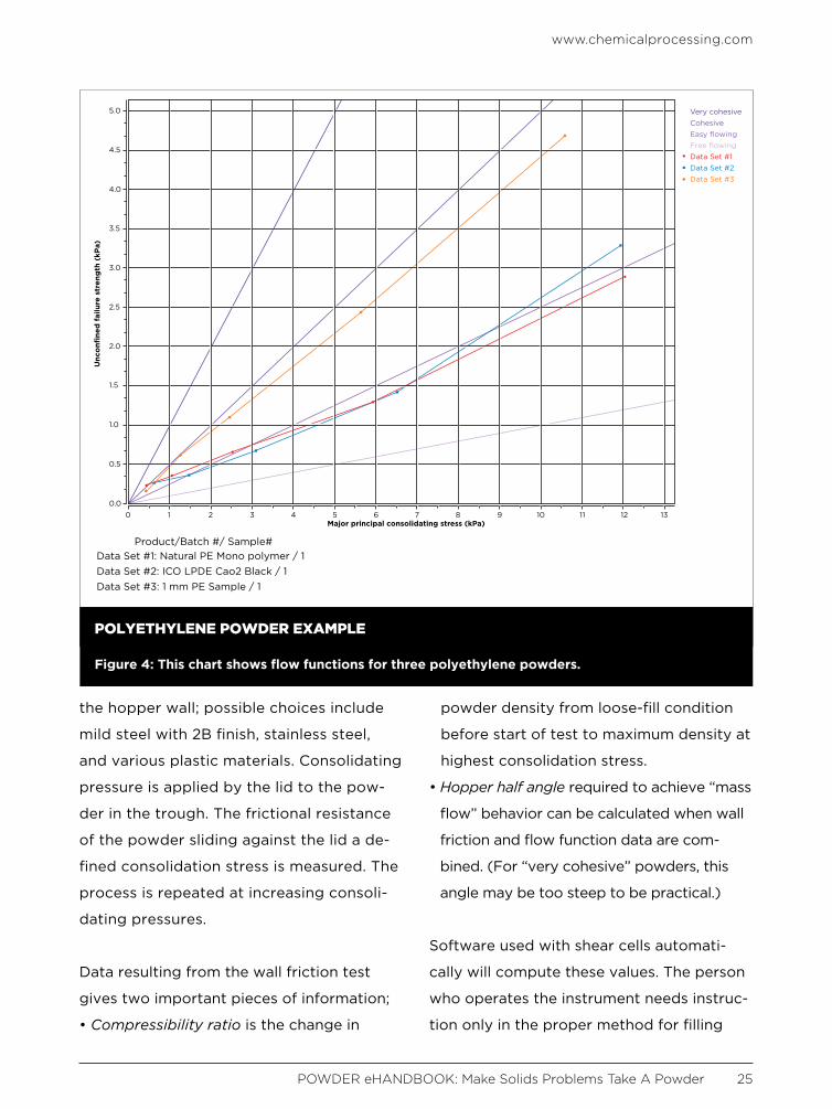
Data from the test generates a flow curve
such as seen in Figure 3. Industry has de-
fined regions of flow behavior as indicated,
ranging from “non-flowing” to “free flow-
ing.” In short, the flow function offers a
convenient tool to quantify the flow behav-
ior of a given powder. Most important, it
provides a quick way to compare powder
batches and identify variations between for-
mulations.To characterize a powder rapidly,
certain pieces of information derived from
the flow function may be used for bench-
marking purposes:
• Flow index is the slope of the line drawn
from the data point associated with the
fifth consolidation stress to the origin.
• Arching dimension is the minimum value
required for the hopper opening to pre-
vent bridging of the powder in “mass
flow” behavior (powder flows downward
uniformly toward the hopper opening).
• Rathole diameter is the stable annular ring
of powder that can form in the bin during
“core flow” (also known as “funnel flow”)
behavior. The size of the ring may vary
in diameter as a function of the powder
height in the bin.
Wall friction. The wall friction test is per-
formed in a similar fashion to the flow
function test. Material of construction for
the lid is identical to material constituting
www.chemicalprocessing.com
POWDER eHANDBOOK: Make Solids Problems Take A Powder 24
POWDER FLOW TESTER
Figure 2: The Brookfield powder flow tester is an example of an annular shear cell instru-ment.
FLOW FUNCTION GRAPH
Figure 3: This flow function graph shows failure strength (y-axis) vs. consolidation stress (x-axis) with defined regions for types of flow behavior.
the hopper wall; possible choices include
mild steel with 2B finish, stainless steel,
and various plastic materials. Consolidating
pressure is applied by the lid to the pow-
der in the trough. The frictional resistance
of the powder sliding against the lid a de-
fined consolidation stress is measured. The
process is repeated at increasing consoli-
dating pressures.
Data resulting from the wall friction test
gives two important pieces of information;
• Compressibility ratio is the change in
powder density from loose-fill condition
before start of test to maximum density at
highest consolidation stress.
• Hopper half angle required to achieve “mass
flow” behavior can be calculated when wall
friction and flow function data are com-
bined. (For “very cohesive” powders, this
angle may be too steep to be practical.)
Software used with shear cells automati-
cally will compute these values. The person
who operates the instrument needs instruc-
tion only in the proper method for filling
www.chemicalprocessing.com
POWDER eHANDBOOK: Make Solids Problems Take A Powder 25
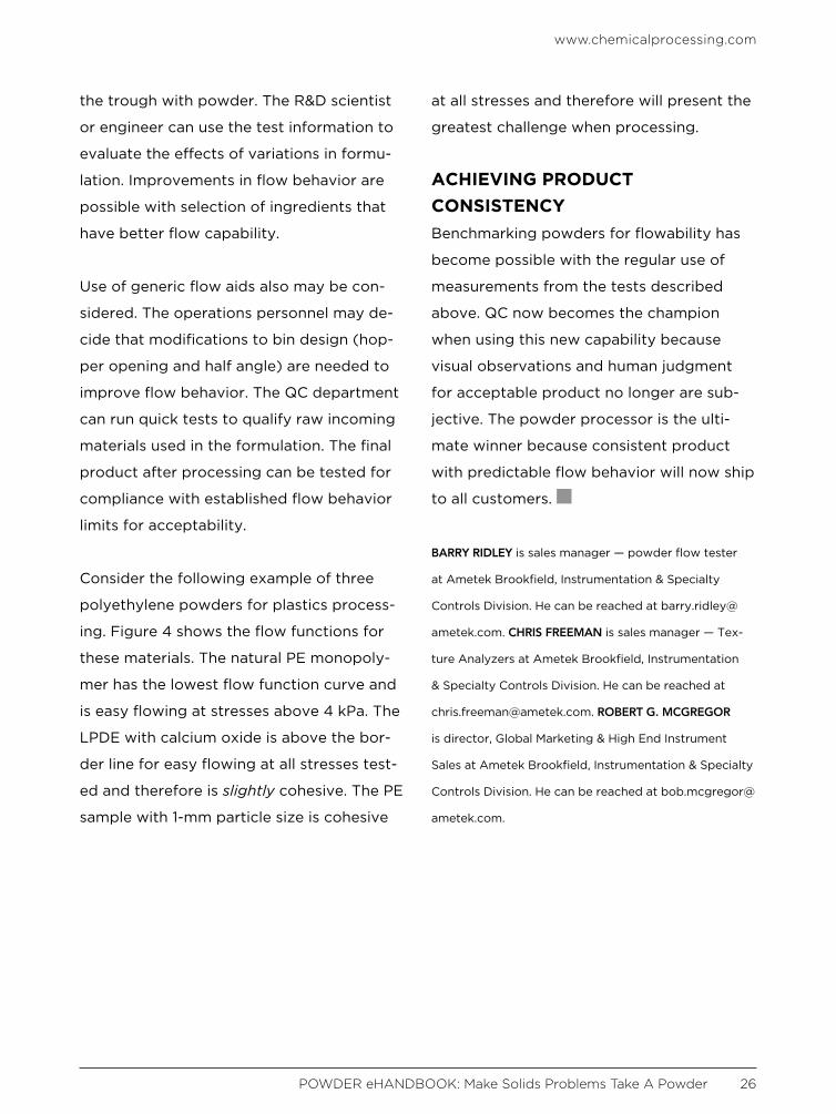
POLYETHYLENE POWDER EXAMPLE
Figure 4: This chart shows flow functions for three polyethylene powders.
Very cohesiveCohesiveEasy flowingFree flowingData Set #1Data Set #2Data Set #3
5.0
4.5
4.0
3.5
3.0
Unc
onfi
ned
fai
lure
str
eng
th (
kPa)
Major principal consolidating stress (kPa)
Product/Batch #/ Sample#Data Set #1: Natural PE Mono polymer / 1Data Set #2: ICO LPDE Cao2 Black / 1Data Set #3: 1 mm PE Sample / 1
2.5
2.0
1.5
1.0
0.5
0.00 1 2 3 4 5 6 7 8 9 10 11 12 13
www.chemicalprocessing.com
POWDER eHANDBOOK: Make Solids Problems Take A Powder 26
the trough with powder. The R&D scientist
or engineer can use the test information to
evaluate the effects of variations in formu-
lation. Improvements in flow behavior are
possible with selection of ingredients that
have better flow capability.
Use of generic flow aids also may be con-
sidered. The operations personnel may de-
cide that modifications to bin design (hop-
per opening and half angle) are needed to
improve flow behavior. The QC department
can run quick tests to qualify raw incoming
materials used in the formulation. The final
product after processing can be tested for
compliance with established flow behavior
limits for acceptability.
Consider the following example of three
polyethylene powders for plastics process-
ing. Figure 4 shows the flow functions for
these materials. The natural PE monopoly-
mer has the lowest flow function curve and
is easy flowing at stresses above 4 kPa. The
LPDE with calcium oxide is above the bor-
der line for easy flowing at all stresses test-
ed and therefore is slightly cohesive. The PE
sample with 1-mm particle size is cohesive
at all stresses and therefore will present the
greatest challenge when processing.
ACHIEVING PRODUCT CONSISTENCYBenchmarking powders for flowability has
become possible with the regular use of
measurements from the tests described
above. QC now becomes the champion
when using this new capability because
visual observations and human judgment
for acceptable product no longer are sub-
jective. The powder processor is the ulti-
mate winner because consistent product
with predictable flow behavior will now ship
to all customers.
BARRY RIDLEY is sales manager — powder flow tester
at Ametek Brookfield, Instrumentation & Specialty
Controls Division. He can be reached at barry.ridley@
ametek.com. CHRIS FREEMAN is sales manager — Tex-
ture Analyzers at Ametek Brookfield, Instrumentation
& Specialty Controls Division. He can be reached at
[email protected]. ROBERT G. MCGREGOR
is director, Global Marketing & High End Instrument
Sales at Ametek Brookfield, Instrumentation & Specialty
Controls Division. He can be reached at bob.mcgregor@
ametek.com.

The goal of powder blending is a ho-
mogeneous, or uniform, consistent
mix of materials. The key to select-
ing a blender that will blend powders to-
gether into uniform mixes, also called “bulk
solids,” is the material’s flow characteristics.
Free-flowing powders are more likely to
blend well together, but not all powders are
free-flowing. Understanding the powder’s
flow characteristics will help determine the
best type of blender for the product.
POWDER FLOW CHARACTERIS-TICSPowders are the least predictable of all ma-
terials in terms of their ability to flow. Two
sets of factors determine a powder’s flow
characteristics: the powder’s variables and
external factors. Powder variables include
the product’s bulk density, particle size, size
distribution, shape, surface texture, cohe-
siveness, surface coating, and electro-static
charge, among others. External factors
include vibration, temperature, humidity,
spurious electrical charges, aeration, con-
tainer surface effects (or wall friction) and
storage time. Addressing only one set of
variables or partially addressing both sets
of variables will lead to flow and, eventually,
blend uniformity problems on the produc-
tion floor. The flow characteristics will help
identify the proper type of blender and the
powder’s weight and density will help de-
termine the size of the blender.
BLENDER SIZEBlenders are volumetric, which means their
sizes are usually measured in terms of their
volume capacity such as cubic feet. Pow-
ders will not blend well (flow) if the blender
Understand Powder Flow CharacteristicsA powder’s variables and external factors will greatly impact blender size and type
By Adam Covitt, Federal Equipment Company
www.chemicalprocessing.com
POWDER eHANDBOOK: Make Solids Problems Take A Powder 28
www.chemicalprocessing.com
POWDER eHANDBOOK: Make Solids Problems Take A Powder 29
is too full or too empty. A safe range of
effectiveness is 35–65% of the overall ca-
pacity. The product’s flow characteristics
will be the best indicator for the capacity
range of each product mixed in the blender.
As a rule of thumb, working capacity of a
blender is usually determined as 50% of the
total volume of the blender. For example, if
a blender has an actual volume of 2 ft3, then
the working capacity will be 1 ft3.
While blenders are generally sized ac-
cording to volume, powders are usually
measured according to density. Such
measurements are either grams per cubic
centimeter (gr/cc) or pounds per cubic
foot (lbs/ ft3). Additionally, the request for
blended materials usually comes in terms
of a specific weight of material such as 15
kilograms (kg) without reference to vol-
ume or density. Powders can be very light
(“fluffy”) or very dense which leads to
different volumes of product at the same
weight (think of a pound of feathers versus
a pound of lead).
The proper blender size for the product
is one that will have a working capac-
ity within the effective range to achieve a
uniform blend. The simple way to calculate
the proper size versus the product density
is to weigh a quart or liter of powder. 16
quarts or 15 liters of a product is equal to 1
ft3 at a density of 35 lbs/ ft3. Blenders sizes
based on 35lbs/ ft3 at working capacity: 1
ft3 = 15kg; 2 ft3 = 30kg; 3 ft3 = 45kg; 5 ft3 =
75kg; 10 ft3 = 150kg; 20 ft3 = 300kg; 30 ft3
= 450kg; and 50 ft3 = 750kg. Size is not the
only factor to consider, the type of blender
is important as well.*
BLENDER TYPESTwin-shell (or “V” blenders), double cone
blenders and bin (or tote) blenders are
all considered “random” style blenders.
These types of blenders also are referred
to as “open shell blenders.” They randomly
mix powders that are already free flowing
through the blender’s tumbling action. If the
products are dense, an intensifier bar can
be added which will force the powders to
move inside the shell of the blender. Liq-
uids may be added to the bulk solids mix-
ture with a liquids bar. Intensifier bars can
be overused which can result in particle
break down for dry and friable powders or
it can pack powders that are wet or cohe-
sive (sticky).
Ribbon and paddle blenders are excellent
ways to mix powders slowly and gently.
In a ribbon blender, a double-helix agita-
tor will move materials towards the center
of a trough with the outer blade while the
inner blades move the materials towards
the outside of the trough. Paddles are an
alternate design that can be used for small
batches relative to the working capacity of
the blender and with friable materials.
High shear mixers are generally used for
products which are considered immiscible,

www.chemicalprocessing.com
POWDER eHANDBOOK: Make Solids Problems Take A Powder 30
where the products to not generally form
a homogeneous blend. The mixer oper-
ates by moving one phase into a continu-
ous phase. The phases, or ingredients, can
be solids, liquids or gases. The ingredients
are moved with a rotor, or impeller, across
other rotors or stators to produce a me-
chanical force called shear which forces
the products to mix. Plow-style mixers are
common high shear mixers that can be
used for particle size reduction and to pro-
duce granules.
These are only a few, common-types of
blenders available. Many additional types of
mixers can be used for powder blending
including planetary mixers, Nauta-style
mixers and single and double-arm mixers
— choices among many others which can be
evaluated applying the same analysis of
weight, capacity and flow characteristics.
Powder flow characteristics and the weight
of the product can be used to determine
the proper type and size of the blender
needed for the product. Analyzing the
weight of the product can be used to
estimate the working capacity required
which determines the overall size of the
blender needed. The flow characteristics
will also determine whether the product can
be blended in a random type blender, a
ribbon or paddle blender, high shear mixer
or some other type of blender.
*Special thanks to Mike Tousey at Techceu-
ticals, LLC for providing the technical infor-
mation described in this article.
ADAM COVITT is vice president for Federal Equipment
Company. He can be reached at [email protected].

POWDER eHANDBOOK: Make Solids Problems Take A Powder 31
Visit the lighter side, featuring draw-
ings by award-winning cartoonist
Jerry King. Click on an image and you
will arrive at a page with the winning
caption and all submissions for that
particular cartoon.
JOIN US ON SOCIAL MEDIA!
ADDITIONAL RESOURCESEHANDBOOKSCheck out our vast library of past eHandbooks that offer a
wealth of information on a single topic, aimed at providing
best practices, key trends, developments and successful
applications to help make your facilities as efficient, safe,
environmentally friendly and economically competitive as
possible.
UPCOMING AND ON DEMAND WEBINARSTap into expert knowledge. Chemical Processing editors
and industry experts delve into hot topics challenging the
chemical processing industry today while providing in-
sights and practical guidance. Each of these free webinars
feature a live Q&A session and lasts 60 minutes.
WHITE PAPERSCheck out our library of white papers covering myriad top-
ics and offering valuable insight into products and solu-
tions important to chemical processing professionals. From
automation to fluid handling, separations technologies and
utilities, this white paper library has it all.
MINUTE CLINICChemical Processing’s Minute Clinic podcast series is de-
signed to tackle one critical issue at a time — giving you
hard-hitting information in just minutes.
ASK THE EXPERTSHave a question on a technical issue that needs to be ad-
dressed? Visit our Ask the Experts forum. Covering topics
from combustion to steam systems, our roster of leading
subject matter experts, as well as other forum members,
can help you tackle plant issues.
TOP COMICAL PROCESSING