mageba flexible plug expansion joint – the new … joints POLYFLEX®ADVANCED PU maximum driving...
8
Expansion joints POLYFLEX®ADVANCED PU maximum driving comfort, wear-resistant, waterght mageba flexible plug expansion joint – the new generaon Switzerland www.mageba.ch
Transcript of mageba flexible plug expansion joint – the new … joints POLYFLEX®ADVANCED PU maximum driving...

Expansion joints
POLYFLEX®ADVANCED PUmaximum driving comfort, wear-resistant, watertight
mageba flexible plug expansion joint –the new generation
Switzerland www.mageba.ch
2
②
①
③
④
⑧⑥
⑦ ⑨
⑤
Expansion joints
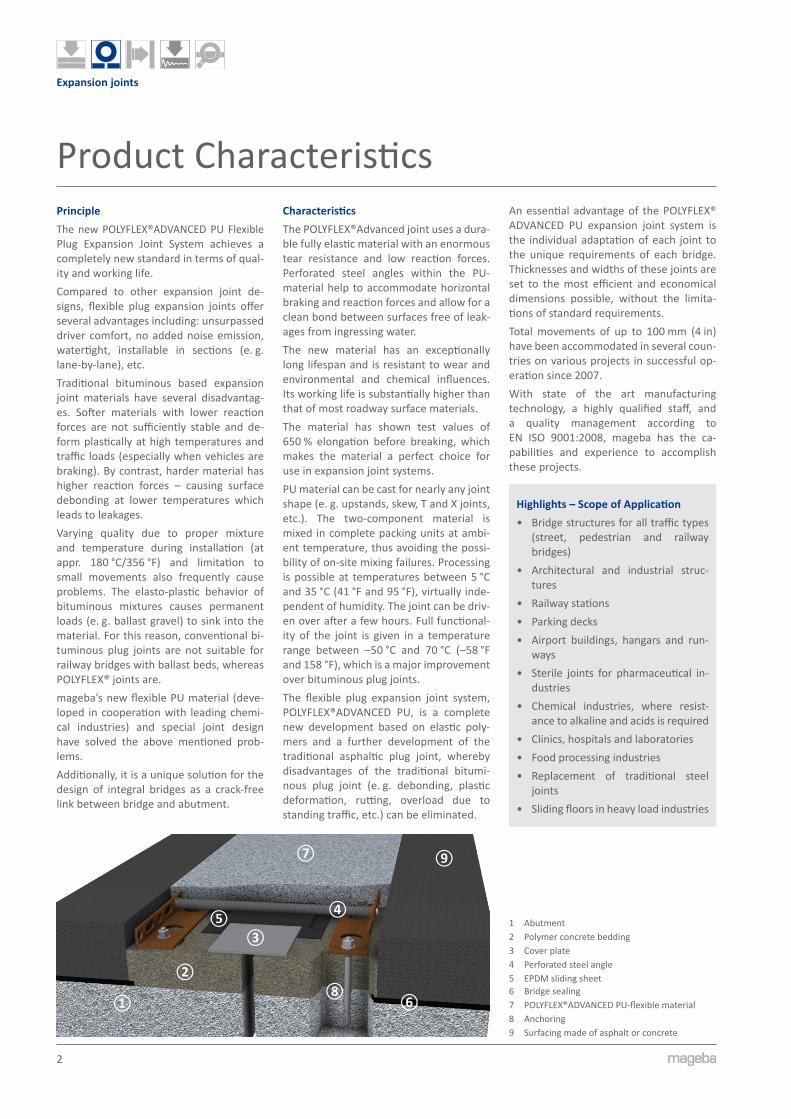
Product CharacteristicsPrincipleThe new POLYFLEX®ADVANCED PU Flexible Plug Expansion Joint System achieves a completely new standard in terms of qual-ity and working life.Compared to other expansion joint de- signs, flexible plug expansion joints offer several advantages including: unsurpassed driver comfort, no added noise emission, watertight, installable in sections (e. g. lane-by-lane), etc.Traditional bituminous based expansion joint materials have several disadvantag-es. Softer materials with lower reaction forces are not sufficiently stable and de-form plastically at high temperatures and traffic loads (especially when vehicles are braking). By contrast, harder material has higher reaction forces – causing surface debonding at lower temperatures which leads to leakages.Varying quality due to proper mixture and temperature during installation (at appr. 180 °C/356 °F) and limitation to small movements also frequently cause problems. The elasto-plastic behavior of bituminous mixtures causes permanent loads (e. g. ballast gravel) to sink into the material. For this reason, conventional bi-tuminous plug joints are not suitable for railway bridges with ballast beds, whereas POLYFLEX® joints are.mageba’s new flexible PU material (deve-loped in cooperation with leading chemi-cal industries) and special joint design have solved the above mentioned prob-lems.Additionally, it is a unique solution for the design of integral bridges as a crack-free link between bridge and abutment.
CharacteristicsThe POLYFLEX®Advanced joint uses a dura-ble fully elastic material with an enormous tear resistance and low reaction forces. Perforated steel angles within the PU-material help to accommodate horizontal braking and reaction forces and allow for a clean bond between surfaces free of leak-ages from ingressing water.The new material has an exceptionally long lifespan and is resistant to wear and environmental and chemical influences. Its working life is substantially higher than that of most roadway surface materials.The material has shown test values of 650 % elongation before breaking, which makes the material a perfect choice for use in expansion joint systems.PU material can be cast for nearly any joint shape (e. g. upstands, skew, T and X joints, etc.). The two-component material is mixed in complete packing units at ambi-ent temperature, thus avoiding the possi-bility of on-site mixing failures. Processing is possible at temperatures between 5 °C and 35 °C (41 °F and 95 °F), virtually inde-pendent of humidity. The joint can be driv-en over after a few hours. Full functional-ity of the joint is given in a temperature range between –50 °C and 70 °C (–58 °F and 158 °F), which is a major improvement over bituminous plug joints.The flexible plug expansion joint system, POLYFLEX®ADVANCED PU, is a complete new development based on elastic poly-mers and a further development of the traditional asphaltic plug joint, whereby disadvantages of the traditional bitumi-nous plug joint (e. g. debonding, plastic deformation, rutting, overload due to standing traffic, etc.) can be eliminated.
An essential advantage of the POLYFLEX® ADVANCED PU expansion joint system is the individual adaptation of each joint to the unique requirements of each bridge. Thicknesses and widths of these joints are set to the most efficient and economical dimensions possible, without the limita-tions of standard requirements.Total movements of up to 100 mm (4 in) have been accommodated in several coun-tries on various projects in successful op-eration since 2007.With state of the art manufacturing technology, a highly qualified staff, and a quality management according to EN ISO 9001:2008, mageba has the ca-pabilities and experience to accomplish these projects.
Highlights – Scope of Application• Bridge structures for all traffic types
(street, pedestrian and railway bridges)
• Architectural and industrial struc-tures
• Railway stations• Parking decks• Airport buildings, hangars and run-
ways• Sterile joints for pharmaceutical in-
dustries• Chemical industries, where resist-
ance to alkaline and acids is required• Clinics, hospitals and laboratories• Food processing industries• Replacement of traditional steel
joints• Sliding floors in heavy load industries
1 Abutment2 Polymer concrete bedding3 Cover plate4 Perforated steel angle5 EPDM sliding sheet6 Bridge sealing7 POLYFLEX®ADVANCED PU-flexible material8 Anchoring9 Surfacing made of asphalt or concrete

3
Expansion joints
Client BenefitsAdvantages & Properties• Exceptional long working life, longer
than adjacent surfaces• Highest possible driver comfort• No noise from crossing traffic due to
surface that is flush with adjacent road• Watertight• Maintenance-free; cleaning not re-
quired• Suitable for new structures and refur-
bishments• Quickly installed lane-by-lane with mini-
mal impact on traffic, drivable after a few hours (overnight installation)
• Installation within a wide temperature range (5 °C to 35 °C/41 °F to 95 °F)
• Wear-resistant; no mechanical wear parts
• No rutting, high resistance to abrasion (e. g. braking traffic, mountain areas, etc.)
• Damages in the joint can be easily repaired by reactivation of the PU ma-terial (e. g. scratches from snowplows etc.),
• No recess for anchorage in structural concrete necessary
• Surfacing (asphalt or concrete) can be applied continuously before joint instal- lation
• Any horizontal bend in the direction of joint possible
• Any curb/sidewalk detail possible• No noise emission due to tire impact
with adjacent structural parts• Not susceptible to vibrations• Low reaction forces• Cold processing and easy material han-
dling with preset mixing ratio, thus no mixing defects
• Resistant to environmental influences and chemicals
• Resistant to alkaline, acids, chlorides, etc.
• Free of germs and fungus• Color available in gray and black• Smooth surface ideal for walking areas
of airports or railway stations
Damage Repair & Partial InstallationsTraffic accidents or road maintenance vehi-cles such as snowplows can cause damage to traditional expansion joints leading to high repair costs.Local damages to the POLYFLEX®ADVANCED PU joint material are repaired easily by cutting out the affected areas from the surface followed by chemical reactivating the cured PU material.Then, the damaged areas can be filled up with new PU material and the surface coating, if any, can be applied to the refur-bished areas.A similar procedure of chemically reacti vating cured material is done at partial in- stallations, e. g. if a lane-by-lane installa-tion is necessary.
ExamplesStandard Road ①POLYFLEX®ADVANCED PU joint for road bridges with continuously applied surfac-ing before joint installation. Useable for new bridges with high loads and large movements, as integral bridge joint filler or for refurbishment.
Standard Light Load ②This POLYFLEX®ADVANCED PU joint design with reduced width and small perforated steel angles is used for light loads (e. g. rail- way bridges, park decks, airport or railway station joints, commercial build-ings, industrial plants).
Intersections ③Intersection of POLYFLEX®ADVANCED PU joints, such as T-crossing or X-crossing in any shape or angle, is possible. For such cases, please contact mageba experts.
Vertical Joints ④POLYFLEX®ADVANCED PU material also allows the design of vertical joints with no limit to inclination or width. Butt joints to horizontal joints can be easily casted in any shape.
1
2
3
4

4
Expansion joints
Design Details & Movement Capacity Design PrinciplesThe POLYFLEX®ADVANCED PU filling mate-rial shows excellent adhesion to the sup-porting structure as well as to the adja-cent surfacing, and is therefore capable of safely transferring horizontal loads to the structure.Additionally, perforated steel angles, which are fully embedded within the joint material, are bolted to the structure and can transfer even the highest loads (e. g. from heavy vehicles braking on the joint at downward slopes).These steel angles also support the adja-cent surfacing so as to prevent the asphalt from being depressed into the sides of the joint material.
Note: �Achievable� movements� in� Serviceability� Limit� State� (SLS)� observing�maximum� permissible� vertical��deflections.� at� Ultimate� Limit� State� (ULS)� significantly� larger� movements� can� be� accommodated.��Please�contact�mageba�experts�for�further�details.�For�refurbishments,�the�actual�width�of�the�struc-tural�gap�shall�be�considered�for�detail�design�of�joint.
It is strongly recommended to use addi-tional transition strips and/or support ribs to secure the strength of adjacent bitumi-nous surfacing areas.A cover plate bridges the structural gap and is designed to withstand all traffic loads while stabilizing elements within the joint material restrain vertical displace-ments to limited values. These values are derived from the “ETAG 032 – Guideline for European Technical Approvals of Ex-pansion Joints for Road Bridges“ and en-sure traffic safety as well as for a perfect driver comfort.The waterproofing membrane of the structure is integrated into the joint filling
material or the polymer concrete bedding material for the substructure to make the whole system watertight.
DimensionsThe tables below show examples of joint dimensions for a preliminary design stage. For final design, the width and height of the joint are individually determined ac-cording to the actual movements. All joint types can accommodate vertical move-ments of ±10 mm for replacement of bridge bearings.
System Types PA 15 – PA 50 (without stabilizing elements)
PA 15 PA 20 PA 30 PA 40 PA 50[mm] [mm] [mm] [mm] [mm]
total movement e 15 20 30 40 50
movement tension e+ 10 13 20 26 33
movement compression e- 5 7 10 14 17
thickness D 60 60 60 60 60
joint width in middle position B0 290 330 290 330 330 360 360 390 430 430 460
gap at middle position S0 10-36 10-60 12-27 12-67 15-47 15-60 19-36 19-54 22-47 22-77 22-100
bridging element width bB 80 120 80 120 120 150 120 150 150 180 220
sliding sheet width bF 80 120 80 120 120 150 150 180 220 220 250
steel angle 70 x 45 x 6
System Types PA 60 – PA 135 (with stabilizing elements)
PA 60 PA 75 PA 80 PA 90 PA 100 PA 110 PA 120 PA 130 PA 135[mm] [mm] [mm] [mm] [mm] [mm] [mm] [mm] [mm]
total movement e 60 75 80 90 100 110 120 130 135
movement tension e+ 40 50 53 60 66 74 80 86 90
movement compression e- 20 25 27 30 34 36 40 44 45
thickness D 70
joint width in middle position B0 500 500 520 580 580 650 730 800 880 950 1030 1100
gap at middle position S0 22-36 25-63 25-100 30-41 30-80 32-70 35-56 39-69 41-48 45-52 49-54 50
bridging element width bB 150 180 220 180 220 220 220 250 250 270 290 290
sliding sheet width bF 250 250 270 330 330 400 480 550 630 700 780 850
steel angle 90 x 55 x 6
stabilizing element distance eS 200 150
D+10
-0
60
Soe+/e-
Zentrierungcentering[Bo±10] e+/e-
15 90 1590bB
bF
Bela
gsst
ärke
laye
r th
ickn
ess
Ø12
≥70
Zentrierungcentering
50
[Bo±10] e+/e-
Soe+/e-
15 70 1570bB
bF
D+10
-0
Bela
gsst
ärke
laye
r th
ickn
ess
≥70 Ø12

5
Expansion joints
Testing and VerificationWheel tracking comparison testA wheel tracking test according to EN 12697-22 was performed by the Testing Institute MAPAG in August of 2009. Test-ing was done on two different flexible plug joint systems with the following results:
Estimation of working life:
conventional asphaltic plug expan-sion joints (picture ①) 0
BT 16 HS LKS (common asphaltic surfacing) 1
POLYFLEX®ADVANCED PU (picture ②) ≥ 2
In practice, this means that the expected working life for POLYFLEX®ADVANCED PU flexible plug expansion joints will be more than 2 times higher than the working life of the adjacent road surfacing.
Mechanical Resistance and Resistance to FatigueAt the testing facility of Technical Uni-versity of Munich, Germany (Prüfamt für Verkehrswegebau, TU München) tests of mechanical resistance and resistance to fa-tigue according to ETAG 032-3, Annex 3-M were carried out on two test specimens of a PA 75 POLYFLEX®ADVANCED PU expansion joint.These tests included:• test method a) “resistance to vertical
static load and recovery after unload-ing“ and
• test method b) “resistance to repeated vertical dynamic load“
Test method a) was carried out at an am- bient temperature of 23 °C ±2 °C (73.4 °F ±3.6 °F) using a mean contact pressure of 0.94 MPa applied with a vertical force of 150 kN through a load distribution pad of 400 x 400 mm simulating the wheel print defined in ETAG 032-1, Annex G. The speci-men further showed an opening position of 100 % of the declared value for the test-ed type PA75.After applying the load for 5 minutes, elas-tic deformations and recovery during the following hour were recorded. The record-ings showed a highest value for elastic de-formation of 0.5 mm directly after unload-ing and a full recovery after one hour.
The test was then carried out again after cutting the load distribution pad in two halves resulting in a halved wheel print of 400 x 200 mm and a doubled mean contact pressure of 1.87 MPa. Even un-der these extreme testing conditions, the highest elastic deformation was only 1.4 mm and the remaining deformation after one hour was only 0.5 mm directly under the load distribution pad.Test method b) was a “classic“ roll-over test carried out at an inner specimen tem-perature of 45 °C (113 °F) using standard twin tires 7.50R15. The tires were verti-cally loaded with 45 kN and inflated with a pressure of 10 bar (145 psi) resulting in a contact pressure of approximately 1.0 MPa – more than twice the required value of 0.46 MPa as per ETAG 032-3. The roll-over speed was chosen as 0.2 m/s and a lateral shifting of wheel tracks in a range of ±2 cm was simulated. The specimen was showing an opening position of 60 % of the declared value for the tested type. Next, 3,000 roll-over cycles were carried out followed by another 30 cycles with a simulated braking force of 10 % of the ver-tical load. The number of load cycles was 50% higher than the 2,000 cycles required according to ETAG 032-3.The surface profile was recorded after every 500 cycles to show possible effects of wheel tracking, but the elastic deforma-tions were negligibly small and no remain-ing wheel tracking was recorded!
2
3
4
1
1 Traditional bituminous plug joint after 100 load cycles at 60 °C (140 °F)
2 POLYFLEX®ADVANCED PU expansion joint after 30,000 load cycles at 60 °C (140 °F)
3 Resistance to vertical static load and recovery after unloading
4 Resistance to repeated vertical dynamic load
6
Expansion joints
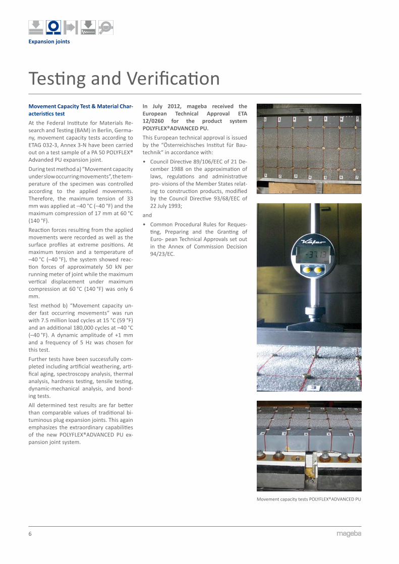
Movement Capacity Test & Material Char-acteristics testAt the Federal Institute for Materials Re- search and Testing (BAM) in Berlin, Germa- ny, movement capacity tests according to ETAG 032-3, Annex 3-N have been carried out on a test sample of a PA 50 POLYFLEX® Advanded PU expansion joint.During test method a) “Movement capacity under slow occurring movements“, the tem-perature of the specimen was controlled according to the applied movements. Therefore, the maximum tension of 33 mm was applied at –40 °C (–40 °F) and the maximum compression of 17 mm at 60 °C (140 °F).Reaction forces resulting from the applied movements were recorded as well as the surface profiles at extreme positions. At maximum tension and a temperature of –40 °C (–40 °F), the system showed reac-tion forces of approximately 50 kN per running meter of joint while the maximum vertical displacement under maximum compression at 60 °C (140 °F) was only 6 mm.Test method b) “Movement capacity un-der fast occurring movements“ was run with 7.5 million load cycles at 15 °C (59 °F) and an additional 180,000 cycles at –40 °C (–40 °F). A dynamic amplitude of +1 mm and a frequency of 5 Hz was chosen for this test.Further tests have been successfully com- pleted including artificial weathering, arti- fical aging, spectroscopy analysis, thermal analysis, hardness testing, tensile testing, dynamic-mechanical analysis, and bond-ing tests.All determined test results are far better than comparable values of traditional bi-tuminous plug expansion joints. This again emphasizes the extraordinary capabilities of the new POLYFLEX®ADVANCED PU ex-pansion joint system.
In July 2012, mageba received the European Technical Approval ETA 12/0260 for the product system POLYFLEX®ADVANCED PU.This European technical approval is issued by the “Österreichisches Institut für Bau- technik“ in accordance with:• Council Directive 89/106/EEC of 21 De-
cember 1988 on the approximation of laws, regulations and administrative pro- visions of the Member States relat-ing to construction products, modified by the Council Directive 93/68/EEC of 22 July 1993;
and• Common Procedural Rules for Reques-
ting, Preparing and the Granting of Euro- pean Technical Approvals set out in the Annex of Commission Decision 94/23/EC.
Testing and Verification
Movement capacity tests POLYFLEX®ADVANCED PU
7
Expansion joints
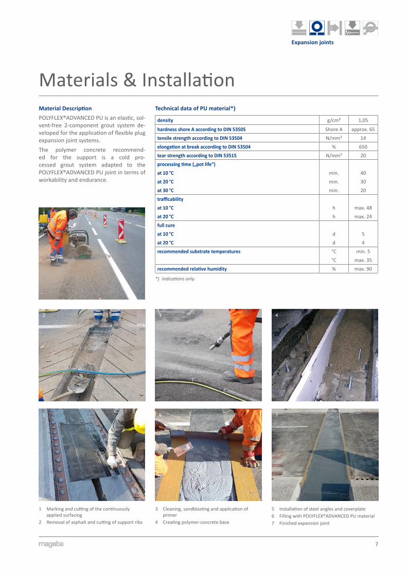
Materials & InstallationMaterial DescriptionPOLYFLEX®ADVANCED PU is an elastic, sol- vent-free 2-component grout system de- veloped for the application of flexible plug expansion joint systems.The polymer concrete recommend-ed for the support is a cold pro-cessed grout system adapted to the POLYFLEX®ADVANCED PU joint in terms of workability and endurance.
2
7
Technical data of PU material*)
density g/cm³ 1,05
hardness shore A according to DIN 53505 Shore A approx. 65
tensile strength according to DIN 53504 N/mm² 14
elongation at break according to DIN 53504 % 650
tear strength according to DIN 53515 N/mm² 20
processing time („pot life“)
at 10 °C min. 40
at 20 °C min. 30
at 30 °C min. 20
trafficability
at 10 °C h max. 48
at 20 °C h max. 24
full cure
at 10 °C d 5
at 20 °C d 4
recommended substrate temperatures °C min. 5
°C max. 35
recommended relative humidity % max. 90
*) indications�only.
1
4
6
1 Marking and cutting of the continuously applied surfacing
2 Removal of asphalt and cutting of support ribs
3 Cleaning, sandblasting and application of primer
4 Creating polymer-concrete base
5 Installation of steel angles and coverplate6 Filling with POLYFLEX®ADVANCED PU material7 Finished expansion joint
3
5
1
2
Expansion joints
Quality & Support
Reference projects – POLYFLEX®ADVANCED PU
InstallationFor new structures, the bituminous surfac-ing shall be made in advance. For concrete surfacing and at edge beams, adequate re-cesses shall be provided.If the joint is installed upon a concrete support, the minimal nominal compres-sive strength must be 25 N/mm².To ensure watertightness of the whole sys- tem, the waterproofing membrane shall be applied up to the bridge gap. During installation of the POLYFLEX®ADVANCED PU joint, the waterproofing is cut and inte-grated into the PU material or the polymer concrete substructure.
Consultingmageba offers full technical support to help determine the proper joint width and details with consideration of all technical and economic aspects in order to calculate the optimum and most cost-effective solu-tion.POLYFLEX®ADVANCED PU flexible plug ex-pansion joints can be installed either by mageba personnel or by customer person-nel, so long as they are specially trained and certified by mageba. Supervision of installation works can also be provided by mageba experts upon request.A valid ISO 9001 certification, 100 % facto-ry production control and continuous third party quality control by a German govern-mental body, the Material Testing Institute of the University in Stuttgart (MPA) ensure both the high quality level of products and manufacturing facilities.mageba product specialists are pleased to provide advice in the selection of the opti-mal solution for any project and to provide pricing.Please visit www.mageba.ch for further product information, including reference lists and tender documentation.
Cantilever finger joints Modular expansion jointsSliding finger jointsSingle gap joints
mageba expansion joint types
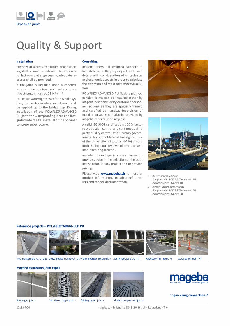
1 A7 Elbtunnel-Hamburg, Equipped with POLYFLEX®Advanced PU expansion joints type PA 40
2 Airport Schipol, Netherlands Equipped with POLYFLEX®Advanced PU expansion joints type PA 30
Neudrossenfeld A 70 (DE) Avrasya Tunnel (TR)Riefensberger Brücke (AT) Schnellstraße S 10 (AT) Kabutotori Bridge (JP)Dreyerstraße-Hannover (DE)
Switzerland www.mageba.ch
2018.04 CH-EN ©mageba mageba sa - Solistrasse 68 - 8180 Bülach - Switzerland - T +41 44 872 40 50 - [email protected]