MAE TUEN HYDROPOWER PROJECT - … AUXILIARIES, TURBINE MODEL TEST, ... with this requirement shall...
186
MAE TUEN HYDROPOWER PROJECT CHIANGMAI PROVINCE CONTRACT C2 ELECTRO-MECHANICAL EQUIPMENT VOLUME 2 TECHNICAL SPECIFICATIONS PANYA CONSULTANTS CO., LTD. JULY 2013
Transcript of MAE TUEN HYDROPOWER PROJECT - … AUXILIARIES, TURBINE MODEL TEST, ... with this requirement shall...

MAE TUEN HYDROPOWER PROJECT
CHIANGMAI PROVINCE
CONTRACT C2
ELECTRO-MECHANICAL EQUIPMENT
VOLUME 2
TECHNICAL SPECIFICATIONS
PANYA CONSULTANTS CO., LTD.
JULY 2013
SUPPLY AND INSTALLATION OF ELECTRO-MECHANICAL POWER PLANT EQUIPMENT MAE TUEN HYDROPOWER PROJECT VOLUME 2 TECHNICAL SPECIFICATIONS
CONTENT
MT-C2V2_Content-sum/1216 2013
MAE TUEN HYDROPOWER PROJECT
CONTRACT C2
SUPPLY AND INSTALLATION OF ELECTRO-MECHANICAL POWER PLANT EQUIPMENT
VOLUME 2 : TECHNICAL SPECIFICATIONS
CONTENTS
PAGE SECTION 1 GENERAL 1-1 SECTION 2 TURBINES AND GOVERNORS 2-1 SECTION 3 INLET VALVES 3-1 SECTION 4 TESTS FOR TURBINE, GOVERNOR INLET VALVE 4-1 AND AUXILIARIES, TURBINE MODEL TEST, TURBINE FIELD EFFICIENCY TEST SECTION 5 MECHANICAL AUXILIARY EQUIPMENT 5-1 SECTION 6 TESTS FOR MECHANICAL AUXILIARY 6-1 EQUIPMENT SECTION 7 GENERATORS AND AUXILIARIES 7-1 SECTION 8 AC STATION SERVICE TRANSFORMERS AND 8-1 AC SWITCH BOARD SECTION 9 TRANFORMER TERMINAL CUBICLES, GENERATOR 9-1 TERMINAL, BUS DUCTS AND NEUTRAL CUBICLES SECTION 10 DC STATION SERVICES 10-1 SECTION 11 CONTROL, PROTECTION AND ALARM SYSTEM 11-1 SECTION 12 MAIN TRANSFORMERS 12-1 SECTION 13 COMMUNICATION SYSTEM 13-1 SECTION 14 ELECTRICAL AUXILIARY EQUIPMENT 14-1
SUPPLY AND INSTALLATION OF ELECTRO-MECHANICAL POWER PLANT EQUIPMENT MAE TUEN HYDROPOWER PROJECT VOLUME 2 TECHNICAL SPECIFICATIONS
CONTENT
MT-C2V2_Content/1216 I 2013
MAE TUEN HYDROPOWER PROJECT
CONTRACT C2
SUPPLY AND INSTALLATION OF ELECTRO-MECHANICAL POWER PLANT EQUIPMENT
VOLUME 2 : TECHNICAL SPECIFICATIONS
CONTENTS
PAGE
SECTION 1 - GENERAL
S1.01 GENERAL 1-1
S1.02 SERVICE CONDITIONS 1-1 S1.03 REGULATIONS AND STANDARDS 1-1 S1.04 UNITS OF MEASUREMENTS 1-3 S1.05 MAINTENANCE TOOLS AND INSTRUMENTS 1-4 S1.06 SPARE PARTS 1-5 S1.07 ERECTION, OPERATION AND MAINTENANCE INSTRUCTIONS 1-6 S1.08 DRAWING 1-11 S1.09 PACKING 1-12 S1.10 PHOTOGRAPHS 1-13 S1.11 LABELS 1-13 S1.12 PAINTING 1-14 S1.13 LOCKING FACILITIES 1-17 S1.14 TROPICALIZATION 1-18 S1.15 MISCELLANEOUS METALWORK 1-19 S1.16 EMBEDMENT, FOUNDATIONS AND PLINTHS 1-19 S1.17 POSITION OF INSTRUMENTS, CONTROLS AND HANDWHEELS 1-20 S1.18 FABRICATION AND WELDING 1-20 S1.19 PIPING, VALVES AND THREADED FASTENERS 1-23 S1.20 CASTING AND PATTERNS 1-27 S1.21 LUBRICATION 1-27 S1.22 SELF-LUBRICATING BUSHES 1-28 S1.23 TEST, GENERAL REQUIREMENTS 1-28 S1.24 ELECTRICAL EQUIPMENT 1-30 S1.25 OPERATOR TRAINING 1-36 SECTION 2 - TURBINES AND GOVERNORS S2.01 SCOPE OF WORK 2-1 S2.02 TURBINE 2-1 S2.03 GOVERNOR 2-11
SUPPLY AND INSTALLATION OF ELECTRO-MECHANICAL POWER PLANT EQUIPMENT MAE TUEN HYDROPOWER PROJECT VOLUME 2 TECHNICAL SPECIFICATIONS
CONTENT
MT-C2V2_Content/1216 II 2013
CONTENTS (Cont’d) PAGE SECTION 3 - INLET VALVES S3.01 TYPE AND CONSTRUCTION 3-1 S3.02 OPERATION 3-1 S3.03 CONTROL AND INDICATION 3-2 S3.04 BYPASS VALVE 3-2 S3.05 DISMANTLING JOINT AND CLOSING PIECE 3-3 S3.06 PRESSURE CONDUIT AND TURBINE DRAIN SYSTEMS 3-3 SECTION 4 - TESTS FOR TURBINE, GOVERNOR INLET VALVE AND AUXILIARIES, TURBINE MODEL TEST, TURBINE FIELD EFFICIENCY TEST S4.01 TESTS FOR TURBINE, GOVERNOR, INLET VALVE AND 4-1 AUXILIARIES S4.02 TURBINE FIELD EFFICIENCY TEST 4-4 SECTION 5 - MECHANICAL AUXILIARY EQUIPMENT S.5.01 UNIT COOLING WATER SYSTEM 5-1 S5.02 COMPRESSED AIR SYSTEM (IF NECESSARY) 5-3 S5.03 VENTILATION AND AIR-CONDITIONING SYSTEMS 5-4 S5.04 POWERHOUSE WATER DRAINAGE SYSTEM 5-5 S5.05 PORTABLE FIRE EXTINGUISHERS 5-6 S5.06 OVERHEAD TRAVELING CRANE 5-7 S5.07 DIESEL-DRIVEN STANDBY ELECTRIC POWER SYSTEM 5-11 SECTION 6 - TESTS FOR MECHANICAL AUXILIARY EQUIPMENT S6.01 TEST DURING MANUFACTURE 6-1 S6.02 TESTS AT SITE 6-1 S6.03 TESTS DURING MANUFACTURE FOR POWERHOUSE CRANE 6-2 S6.04 TESTS AT SITE FOR POWERHOUSE CRANE 6-3 SECTION 7 - GENERATORS AND AUXILIARIES S7.01 GERATORS 7-1 S7.02 SHAFT AND BEARINGS 7-7 S7.03 SIGNAL GENERATOR 7-10 S7.04 EXCITATION SYSTEM 7-11 S7.05 INSPECTION AND TESTS 7-13

SUPPLY AND INSTALLATION OF ELECTRO-MECHANICAL POWER PLANT EQUIPMENT MAE TUEN HYDROPOWER PROJECT VOLUME 2 TECHNICAL SPECIFICATIONS
CONTENT
MT-C2V2_Content/1216 III 2013
CONTENTS (Cont’d) PAGE SECTION 8 - AC STATION SERVICE TRANSFORMERS AND AC SWITCH BOARD S8.01 SCOPE OF WORK 8-1 S8.02 PURPOSE AND FUNCTION 8-1 S8.03 STATION SERVICE TRANSFORMER 8-1 S8.04 HIGH VOLTAGE LOAD INTERRUPTING SWITCH 8-3 (NOT APPLICABLE) S8.05 AUTOMATIC TRANSFER 8-3 S8.06 NO-FUSE BREAKER 8-5 S8.07 SECONDARY WIRING AND TERMINALS 8-5 S8.08 CONTROL SWITCHES AND INDICATION 8-6 S8.09 INTERLOCKING 8-6 S8.10 CURRENT TRANSFORMERS 8-6 S8.11 VOLTAGE TRANSFORMERS (NOT APPLICABLE) 8-7 S8.12 INSTRUMENT SECTIONS 8-7 S8.13 GROUNDING 8-9 S8.14 NAMEPLATES 8-9 S8.15 CHANNEL BASES AND BOLTS 8-9 S8.16 TESTS 8-9 SECTION 9 - TRANFORMER TERMINAL CUBICLES, GENERATOR TERMINAL, BUS DUCTS AND NEUTRAL CUBICLES S9.01 SCOPE OF WORK 9-1 S9.02 PURPOSE AND FUNCTION 9-1 S9.03 STANDARDS 9-2 S9.04 GENERATOR CIRCUIT BREAKER CUBICLES AND BUS 9-2 DUCTS RATINGS S9.05 EQUIPMENT DETAILS 9-2 S9.06 DESIGN AND CONSTRUCTION OF GENERATOR TERMINAL 9-4 CUBICLES S9.07 DESIGN AND CONSTRUCTION OF GENERATOR NEUTRAL 9-7 CUBICLES S9.08 WIRING AND WIRING TROUGHS 9-7 S9.09 TESTS 9-7 SECTION 10 - DC STATION SERVICES S10.01 SCOPE OF WORK 10-1 S10.02 PURPOSE AND FUNCTION 10-1 S10.03 BATTERY 10-1 S10.04 BATTERY RACKS 10-2

SUPPLY AND INSTALLATION OF ELECTRO-MECHANICAL POWER PLANT EQUIPMENT MAE TUEN HYDROPOWER PROJECT VOLUME 2 TECHNICAL SPECIFICATIONS
CONTENT
MT-C2V2_Content/1216 IV 2013
CONTENTS (Cont’d) PAGE S10.05 INSTRUMENT ON DC DISTRIBUTION BOARD 10-2 S10.06 BATTERY CHARGER 10-3 S10.07 DISTRIBUTION PANEL BOARD 10-4 S10.08 CABLE INTERCONNECTION 10-5 S10.09 TESTS 10-5 SECTION 11 - CONTROL, PROTECTION AND ALARM SYSTEM S11.01 GENERAL 11-1 S11.02 CONTROL SYSTEM REQUIREMENTS 11-13 S11.03 PROTECTION DESIGN REQUIREMENTS 11-16 S11.04 GROUP OPERATION INDICATOR 11-20 S11.05 FAULT INDICATOR AND AUDIBLE ALARM SYSTEM 11-20 S11.06 CONTROL AND PROTECTION CUBICLES 11-21 S11.07 TESTS 11-29 SECTION 12 - MAIN TRANSFORMERS S12.01 SCOPE OF WORK 12-1 S12.02 PURPOSE AND FUNCTION 12-1 S12.03 STANDARDS 12-1 S12.04 TYPE OF TRANSFORMER 12-1 S12.05 MEGAVOLT AMPERE RATING 12-1 S12.06 VOLTAGE RATINGS, CONNECTIONS AND TAPS 12-2 S12.07 INSULATION LEVELS 12-2 S12.08 IMPEDANCE AND LOSSES 12-2 S12.09 SHORT CIRCUIT CAPABILITY 12-2 S12.10 SOUND LEVEL 12-2 S12.11 HIGH FREQUENCY INTERFERENCE 12-3 S12.12 BUSHINGS AND CONNECTORS 12-3 S12.13 OFF-LOAD TAP CHANGER 12-3 S12.14 CONSTRUCTION 12-4 S12.15 BASE 12-5 S12.16 TRANSFORMER TANK OR CORRUGATED TANK 12-6 S12.17 CONSERVATOR TANK (IF SELECTED) 12-6 S12.18 RADIATORS OR CORRUGATED TANK 12-6 S12.19 CONTROL 12-7 S12.20 OIL 12-7 S12.21 ACCESSORIES 12-7 S12.22 TESTS 12-8

SUPPLY AND INSTALLATION OF ELECTRO-MECHANICAL POWER PLANT EQUIPMENT MAE TUEN HYDROPOWER PROJECT VOLUME 2 TECHNICAL SPECIFICATIONS
CONTENT
MT-C2V2_Content/1216 V 2013
CONTENTS (Cont’d) PAGE SECTION 13 - COMMUNICATION SYSTEM S13.01 SCOPE OF WORK 13-1 S13.02 PURPOSE, TECHNICAL SPECIFICATIONS, AND PERFORMANCE 13-1 DATA REQUIREMENTS SECTION 14 - ELECTRICAL AUXILIARY EQUIPMENT S14.01 SCOPE OF WORK 14-1 S14.02 WORK INCLUDED 14-1 S14.03 CODES AND STANDARD 14-1 S14.04 CABLE TRAYS AND SUPPORTS 14-1 S14.05 CONDUIT, BOXES AND FITTINGS 14-2 S14.06 750 V WIRE AND CABLE 14-4 S14.07 CONTROL CABLES 14-4 S14.08 STATION CLOCKS 14-6 S14.09 MOTOR CONTROL CENTER 14-6 S14.10 FORE BAY WATER LEVEL TRANSMITTER 14-9
S14.11 TELEPHONE SYSTEM (Not Applicable) 14-10 S14.12 TESTS 14-11 S14.13 HV CABLE END TREATING MATERIAL 14-11

SECTION 1 GENERAL
SUPPLY AND INSTALLATION OF ELECTRO-MECHANICAL POWER PLANT EQUIPMENT MAE TUEN HYDROPOWER PROJECT VOLUME 2 - TECHNICAL SPECIFICATIONS
SECTION 1 – GENERAL
MT-C2V2-sec1/1216 �-� 2013
SECTION 1 - GENERAL
S1.01 GENERAL
(1) These General Specifications apply to all equipment, materials, devices & components, including pre-engineering or bought-out items, procedures, methods, techniques, and workmanship contained in the other Technical Specifications whether referred to specifically or not.
(2) Where the other Technical Specifications conflict with these General
Specifications, the Technical Specifications shall prevail. (3) All works shall be subject to a quality control program developed by the
Contractor which shall be designed to prevent and readily detect and correct non-conformities in quality of the work as specified in this section, or internationally recognized equivalent. The Contractor shall make available to the Engineer details of the quality control program at the Contractor, sub-Contractor, and Manufacturer’s plants which are applicable to the Works before manufacturing begins
(4) The Engineer will be the sole judge of material and workmanship, among all
things, furnished and supplied by the Contractor. No patching, plugging, shimming or other such means to overcome defects, discrepancies or errors shall be employed without the written agreement of the Engineer. Failure to comply with this requirement shall constitute grounds for rejection of the item in question.
(5) Material and equipment not covered by these Specifications shall be subject to
acceptance by the Department.
S1.02 SERVICE CONDITIONS All the equipment shall be designed and manufactured for its particular location for
continuous operation at the extremes of climate as listed in Clause 7.02 of Volume 1. Specifically, all equipment to be installed indoors shall be designed and manufactured for satisfactory continuous operation at an ambient temperature of 40̊ C and all equipment to be installed outside shall be designed and manufactured for satisfactory continuous operation at an ambient temperature of 45˚C. Equipment supplied between ceiling and the roofs shall be designed for satisfactory operation at an ambient temperature of 60˚C.
S1.03 REGULATIONS AND STANDARDS The supply must conform to the laws and regulations existing in the Kingdom of
Thailand, in addition to the particular prescription given in the present Technical Specifications.

SUPPLY AND INSTALLATION OF ELECTRO-MECHANICAL POWER PLANT EQUIPMENT MAE TUEN HYDROPOWER PROJECT VOLUME 2 - TECHNICAL SPECIFICATIONS
SECTION 1 – GENERAL
MT-C2V2-sec1/1216 �-� 2013
All materials and equipment to be incorporated in the Works and the fabrication of
same except as otherwise provided shall conform to the latest edition of the Standards of the Engineering Societies given in the following list:
ANSI American National Standards Institute AGMA American Gear Manufacturers Association AISI American Iron and Steel Institute ASHRAE American Society of Heating, Refrigeration and Air-Conditioning Engineers IEEE Institute of Electrical Electronic Engineers ASME American Society of Mechanical Engineer ASTM American Society for Testing and Materials NEMA National Electrical Manufacturers Association ICEA Insulated Cable Engineer’s Association AWS American Welding Society IEC International Electrotechnical Commission SSPC Steel Structures Painting Council NEC National Electrical Code AISC American Institute of Steel Construction NFPA National Fire Protection Association AWWA American Water Works Association ISA Instrument Society of America ISO International Organization for Standardization AFBMA Anti-Friction Bearing Manufacturers Association CMAA Crane Manufacturer’s Association of America DEMA Diesel Engine Manufacturers Association TIS Thai Industrial Standard The latest edition of each standard shall mean the available edition at the date of
signature of the Contract. Other equivalent standards will be accepted provided that they are proposed with the
Bid and accepted before the award of the Contract. The Contractor shall submit two copies (one to the Department and to the Engineer) of
the equivalent accepted standards in English or with English translation, showing the correspondence with the specified Standards.
If the Contractor, after the award of the Contract, proposes other equivalent Standards
and Specifications and Standards of equivalent material, the Contractor shall state the exact nature of the change, and shall submit complete Standards and Specifications and information and data on the materials for the approval of the DEDE Engineer.
Such submittals shall be timely and failure to do so, or purchase of any proposed
equivalent materials prior to the approval of the DEDE Engineer, will be at the Contractor’s risk.
SUPPLY AND INSTALLATION OF ELECTRO-MECHANICAL POWER PLANT EQUIPMENT MAE TUEN HYDROPOWER PROJECT VOLUME 2 - TECHNICAL SPECIFICATIONS
SECTION 1 – GENERAL
MT-C2V2-sec1/1216 �-� 2013
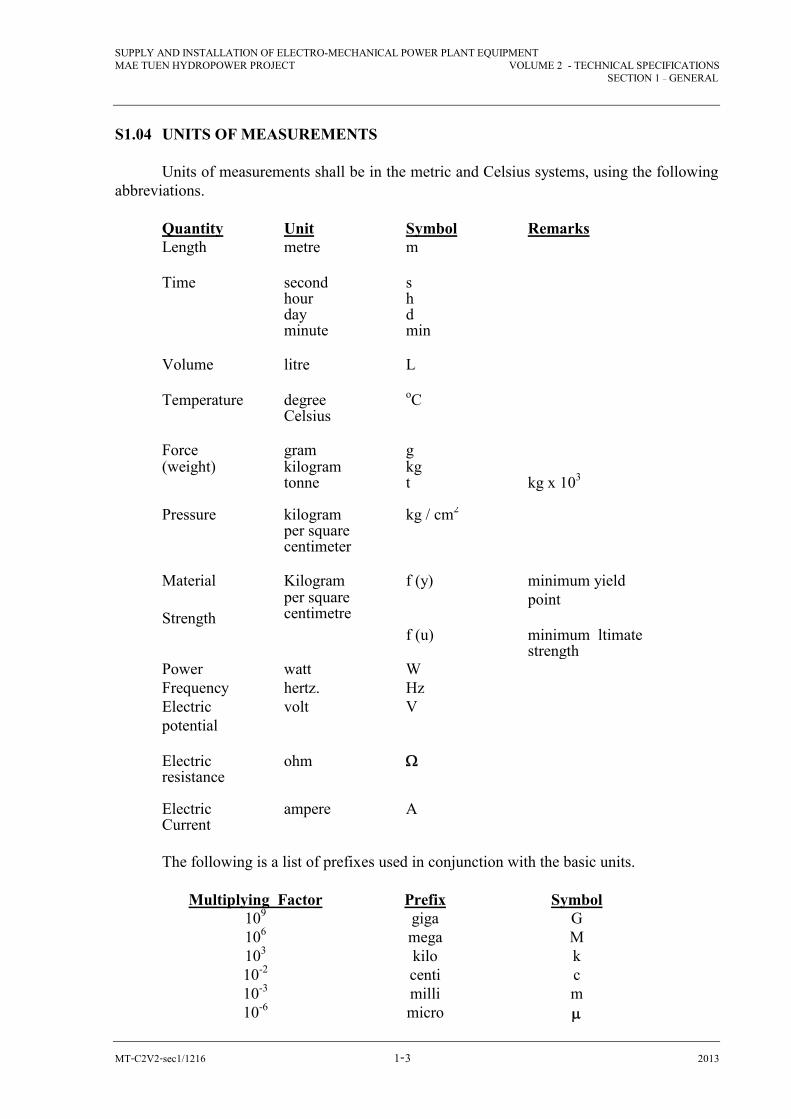
S1.04 UNITS OF MEASUREMENTS Units of measurements shall be in the metric and Celsius systems, using the following abbreviations.
Quantity Unit Symbol Remarks Length metre m
Time second hour day minute
s h d min
Volume litre
L
Temperature degree Celsius
oC
Force gram g (weight) kilogram
tonne kg t
kg x 103
Pressure kilogram
per square centimeter
kg / cm2
Material Kilogram f (y) minimum yield Strength
per square centimetre
point
f (u) minimum ltimate strength
Power watt W Frequency hertz. Hz Electric potential
volt V
Electric resistance
ohm
Electric Current
ampere A
The following is a list of prefixes used in conjunction with the basic units.
Multiplying Factor
109
106 103 10-2 10-3 10-6
Prefix giga mega kilo centi milli micro
Symbol G M k c m
SUPPLY AND INSTALLATION OF ELECTRO-MECHANICAL POWER PLANT EQUIPMENT MAE TUEN HYDROPOWER PROJECT VOLUME 2 - TECHNICAL SPECIFICATIONS
SECTION 1 – GENERAL
MT-C2V2-sec1/1216 �-� 2013
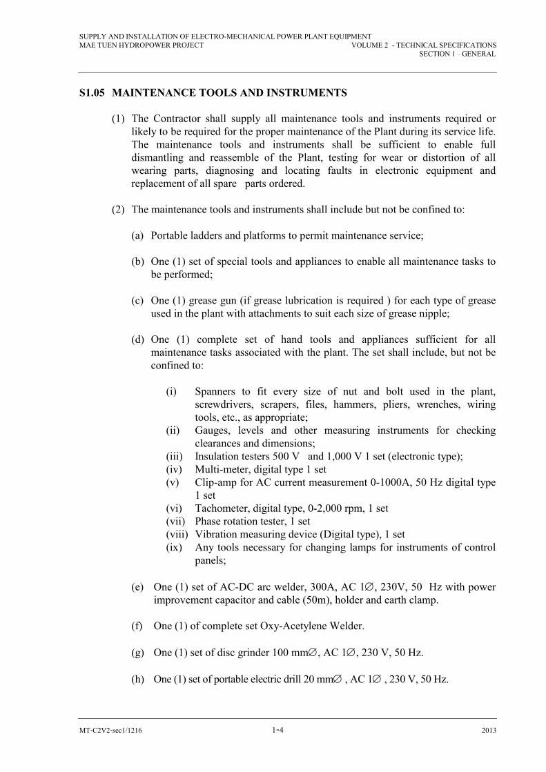
S1.05 MAINTENANCE TOOLS AND INSTRUMENTS (1) The Contractor shall supply all maintenance tools and instruments required or
likely to be required for the proper maintenance of the Plant during its service life. The maintenance tools and instruments shall be sufficient to enable full dismantling and reassemble of the Plant, testing for wear or distortion of all wearing parts, diagnosing and locating faults in electronic equipment and replacement of all spare parts ordered.
(2) The maintenance tools and instruments shall include but not be confined to: (a) Portable ladders and platforms to permit maintenance service; (b) One (1) set of special tools and appliances to enable all maintenance tasks to
be performed; (c) One (1) grease gun (if grease lubrication is required ) for each type of grease
used in the plant with attachments to suit each size of grease nipple; (d) One (1) complete set of hand tools and appliances sufficient for all
maintenance tasks associated with the plant. The set shall include, but not be confined to:
(i) Spanners to fit every size of nut and bolt used in the plant,
screwdrivers, scrapers, files, hammers, pliers, wrenches, wiring tools, etc., as appropriate;
(ii) Gauges, levels and other measuring instruments for checking clearances and dimensions;
(iii) Insulation testers 500 V and 1,000 V 1 set (electronic type); (iv) Multi-meter, digital type 1 set (v) Clip-amp for AC current measurement 0-1000A, 50 Hz digital type
1 set (vi) Tachometer, digital type, 0-2,000 rpm, 1 set (vii) Phase rotation tester, 1 set (viii) Vibration measuring device (Digital type), 1 set (ix) Any tools necessary for changing lamps for instruments of control
panels; (e) One (1) set of AC-DC arc welder, 300A, AC 1, 230V, 50 Hz with power
improvement capacitor and cable (50m), holder and earth clamp. (f) One (1) of complete set Oxy-Acetylene Welder. (g) One (1) set of disc grinder 100 mm, AC 1, 230 V, 50 Hz. (h) One (1) set of portable electric drill 20 mm , AC 1 , 230 V, 50 Hz.

SUPPLY AND INSTALLATION OF ELECTRO-MECHANICAL POWER PLANT EQUIPMENT MAE TUEN HYDROPOWER PROJECT VOLUME 2 - TECHNICAL SPECIFICATIONS
SECTION 1 – GENERAL
MT-C2V2-sec1/1216 �-� 2013
(i) One (1) set of electric hammer drill 19 mm , AC 1 , 230 V, 50 Hz. (j) One (1) set of vacuum cleaner, industrial heavy duty type , AC 1 , 230 V, 50
Hz., 1.5 kW. (k) One (1) set of air compressor, 7 kgf/cm2, 200 liter/min, AC 1, 230 V, 50
Hz. with wheels. (3) The individual tools and appliances shall be listed in price schedule. The prices of
the tools and appliances shall be included in the Contract Price. (4) Any additional maintenance tools and appliances which are required for the proper
maintenance of the Plant as defined in this Clause and which are not listed in Price Schedule, shall be included in the Contract Price.
(5) The Contractor may use the mechanical handling equipment for initial erection of
the Plant but shall make good any wear or damage before handing over.
(6) (a) Maintenance equipment shall be suitably arranged in metal tool boxes of cabinets each fitted with a padlock and 2 keys. Each tool box or cabinet shall be clearly and permanently marked with the name of the plant to which the maintenance tools and instruments apply and with a list of the equipment it contains.
(b) Large tools shall be mounted on a suitable shadow board arranged for wall mounting.
S1.06 SPARE PARTS
(1) All spare parts recommended for the Plant by the Contractor shall be listed in Price Schedule with their individual prices. The spare parts offered shall include all parts subject to normal wear and tear and also such major sub-assemblies as may be subject to accidental damage.
(2) The Department may order all or any of the spare parts at his discretion. The Contractor shall supply the specified and recommended spare parts at the individual prices stated in the price schedule provided that the selection is made by the Department.
(3) All spare parts ordered shall be interchangeable and suitable for use in place of
corresponding parts supplied with the Plant. They shall comply with the Contract and shall be clearly and permanently marked with their descriptions and identification members both on the parts and on the outside of the packages and prepared for permanent storage in an approved manner to prevent deterioration.
SUPPLY AND INSTALLATION OF ELECTRO-MECHANICAL POWER PLANT EQUIPMENT MAE TUEN HYDROPOWER PROJECT VOLUME 2 - TECHNICAL SPECIFICATIONS
SECTION 1 – GENERAL
MT-C2V2-sec1/1216 �-� 2013
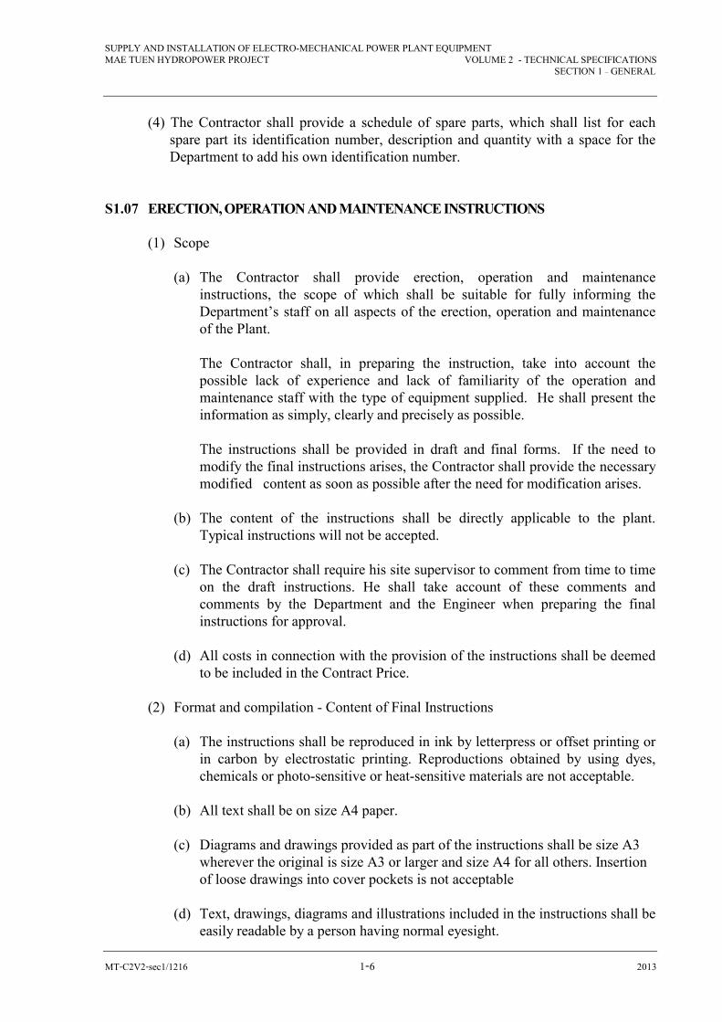
(4) The Contractor shall provide a schedule of spare parts, which shall list for each spare part its identification number, description and quantity with a space for the Department to add his own identification number.
S1.07 ERECTION, OPERATION AND MAINTENANCE INSTRUCTIONS (1) Scope (a) The Contractor shall provide erection, operation and maintenance
instructions, the scope of which shall be suitable for fully informing the Department’s staff on all aspects of the erection, operation and maintenance of the Plant.
The Contractor shall, in preparing the instruction, take into account the possible lack of experience and lack of familiarity of the operation and maintenance staff with the type of equipment supplied. He shall present the information as simply, clearly and precisely as possible.
The instructions shall be provided in draft and final forms. If the need to modify the final instructions arises, the Contractor shall provide the necessary modified content as soon as possible after the need for modification arises.
(b) The content of the instructions shall be directly applicable to the plant. Typical instructions will not be accepted.
(c) The Contractor shall require his site supervisor to comment from time to time
on the draft instructions. He shall take account of these comments and comments by the Department and the Engineer when preparing the final instructions for approval.
(d) All costs in connection with the provision of the instructions shall be deemed
to be included in the Contract Price. (2) Format and compilation - Content of Final Instructions (a) The instructions shall be reproduced in ink by letterpress or offset printing or
in carbon by electrostatic printing. Reproductions obtained by using dyes, chemicals or photo-sensitive or heat-sensitive materials are not acceptable.
(b) All text shall be on size A4 paper. (c) Diagrams and drawings provided as part of the instructions shall be size A3
wherever the original is size A3 or larger and size A4 for all others. Insertion of loose drawings into cover pockets is not acceptable
(d) Text, drawings, diagrams and illustrations included in the instructions shall be
easily readable by a person having normal eyesight.

SUPPLY AND INSTALLATION OF ELECTRO-MECHANICAL POWER PLANT EQUIPMENT MAE TUEN HYDROPOWER PROJECT VOLUME 2 - TECHNICAL SPECIFICATIONS
SECTION 1 – GENERAL
MT-C2V2-sec1/1216 �-� 2013
(e) Each copy of the final instructions shall be bound into loose-leaf volumes in strong, durable, washable, vinyl plastic covers inscribed with bold letters upon the front and spine. A sample of the proposed inscribed covers and binding shall be submitted to the Engineer with the draft instructions for approval.
(3) Program for Delivery of Instructions (a) The Contractor shall deliver the complete draft and the complete final
instructions within the periods nominated in Clause 6.06 of Volume 1. (b) Failure to deliver the required number of copies of approved final instructions
shall be sufficient reason for the Engineer to withhold the issuing of a Provisional Acceptance Certificate in accordance with the Conditions of Contract.
(4) Detailed Instruction Content (a) General (i) Each volume shall have a table of contents for the volume and a list of
the other volumes at the front. (ii) The instructions content for each plant feature, as defined in sub-clause
(1) of this Clause and Table S1.06, shall include, but not necessarily be limited to, all the material required by this sub-clause.
(b) Section 1 - Contents Section
The feature name and list of sections as in sub-clause (1) (d) of this Clause. (c) Section 2 – Introduction (i) Subsection 2.1 - History
Brief description of the basic purpose of the plant feature. Also a brief definition of type of plant with main performance characteristics such as rating, head, speed, voltage.
(ii) Subsection 2.2 - Purpose and Nature Brief statement of the organizations involved in the design, manufacture and erection of the Plant, and date when Plant entered commercial service.
(d) Section 3 - Description
A comprehensive description defining the generic type of plant and component, method of construction, materials of main components, design features, control and protection functions. relationship with other plant and including the description of auxiliaries specific to the plant feature.

SUPPLY AND INSTALLATION OF ELECTRO-MECHANICAL POWER PLANT EQUIPMENT MAE TUEN HYDROPOWER PROJECT VOLUME 2 - TECHNICAL SPECIFICATIONS
SECTION 1 – GENERAL
MT-C2V2-sec1/1216 �-� 2013
(e) Section 4 - Operation (i) Subsection 4 .1 - Operating Sequences
Brief description of the operational functions of which the plant feature is capable and a reference to the instructions volumes covering operation in detail.
(ii) Subsection 4.2 - Operating Limits Tabulated data on limits for all operating parameters and reason for limit.
(iii) Subsection 4.3 - Pre-start check List Comprehensive tabulated list or sequence diagram of all conditions which must be checked before the Plant may be started after being out of service for overhaul or any reason. (This is not intended to cover checks required before each routine start up, i.e., when the plant has been stopped and is nominally ready to re-start on demand).
(iv) Subsection 4.4 - In-service Check List Comprehensive tabulated list of all observations to be made during periodic inspections and tests, defining the location, range of acceptable values and action to be taken if incorrect values are found.
(f) Section 5 - Maintenance (i) Periodic service and maintenance procedures including maintenance
schedules defining:
component and condition to be checked required frequency of checking equipment and stock required required plant condition for service or maintenance including
instructions for isolating the whole or any section of the plant so that maintenance or repairs can be done in complete safety
dismantling sequence and methods inspection of components, detailed checks for condition and criteria
for acceptance, rejection or reconditioning reconditioning, replacement and adjustment procedures re - assembly sequence and methods.
(ii) Fault diagnosis based on symptoms of malfunctions and wear. (iii) Recommissioning procedures after major overhaul. (iv) Lubrication requirements incorporating lubricants recommended in
Clause S1.21 including a comprehensive lubrication chart, instructions on filter maintenance, and instructions on testing and maintenance of lubricating oil.
(v) Testing and maintenance requirements for electrical insulating oils. (vi) Ordering data shall be provided in sufficient detail to allow any part of
sub-assembly to be re- ordered and/or a satisfactory substitute to be made on site. Nameplate information including model and serial number is required for each item of equipment supplied.

SUPPLY AND INSTALLATION OF ELECTRO-MECHANICAL POWER PLANT EQUIPMENT MAE TUEN HYDROPOWER PROJECT VOLUME 2 - TECHNICAL SPECIFICATIONS
SECTION 1 – GENERAL
MT-C2V2-sec1/1216 �-� 2013
(g) Section 6 - Drawings (i) Index of drawings contained in Section 6 of the Instructions. (ii) One copy of drawing referred to in the text or necessary for clear
understanding and use of the text, including all assembly, layout and arrangement drawings.
(h) Section 7 - Brochure for Proprietary Equipment
Manufacturer’s brochures, instruction pamphlets and the like, containing the operation and maintenance information as specified in paragraphs (e) and (f) of this sub-clause in respect of proprietary equipment.
TABLE S1.07
VOL NO. PLANT FEATURE PLANT FEATURE
& TITLE REF. NO. 1. Plant Design
Data and Test Results
All performance data and charts over the full range of operation shall be provided for each plant feature. Table shall list all design clearances, settings, adjustments, voltages, currents, pressures, levels and flows together with the actual values measured or observed during manufacture, delivery, erection or testing as appropriate. All tests carried out at works and at site shall be described and the complete test records and results shall be included.
2. Plant Photo- graphs
This volume shall include the photographs and descriptions required by Clause S1.09 for each plant feature.
3. Erection Instructions
Erection instructions for each plant feature.
4. Turbine Governor Inlet Valve and Ancillaries
4.1 Turbine 4.2 Governor 4.3 Turbine Inlet Valve 4.4 Turbine Control and Protection 4.5 Auxiliary Equipment
5. Mechanical Auxiliary Equipment
5.1 Unit Cooling Water System 5.2 Compressed Air System 5.3 Ventilation and Air-Conditioning Systems 5.4 Water Drainage System 5.5 Powerhouse Crane 5.6 Diesel-driven Standby Electric Power System

SUPPLY AND INSTALLATION OF ELECTRO-MECHANICAL POWER PLANT EQUIPMENT MAE TUEN HYDROPOWER PROJECT VOLUME 2 - TECHNICAL SPECIFICATIONS
SECTION 1 – GENERAL
MT-C2V2-sec1/1216 �-�� 2013
6. Generator and Auxiliaries
6.1 Generator 6.2 Shaft and Bearing 6.3 Signal Generator 6.4 Excitation System
7. AC Station Service Trans- former and Switchboard
7.1 Oil – immersed, natural self-cooled, outdoor Station Service Transformer 7.2 High Voltage Fused Load Interrupter Switches
8. Generator Terminal Cubicles, Bus Ducts and Neutral Cubicles
8.1 Generator PT, CT Cubicles 8.2 Generator Circuit Breaker Cubicles 8.3 Neutral Cubicles
9. DC Station Service
9.1 125 V. Battery with Racks and Fuses 9.2 Instrument and Circuit Breaker Panel 9.3 Battery Charger 9.4 DC Distribution Panel Board
10. Control, Protection and Alarm System
10.1 Main Control Board 10.2 Auxiliary Relay Board
11.
Main Transformer
See detail in section 12
12. Line Protection Equipment 24 kV Switch- gear and Switchyard
12.1 24 kV. Switchgear Recloser 12.2 Switchyard
13. Electrical Auxiliary Equipment
13.1 Cable Trays and Supports 13.2 Conduit, Boxes and Fittings 13.3 HV Cable 13.4 750 V Wire and Cable 13.5 Control Cable 13.6 Station Clocks 13.7 Motor Control Center 13.8 Single Side Band Transceiver and Antenna, VHF Communication system. 13.9 HV Cable End Treating Material
SUPPLY AND INSTALLATION OF ELECTRO-MECHANICAL POWER PLANT EQUIPMENT MAE TUEN HYDROPOWER PROJECT VOLUME 2 - TECHNICAL SPECIFICATIONS
SECTION 1 – GENERAL
MT-C2V2-sec1/1216 �-�� 2013
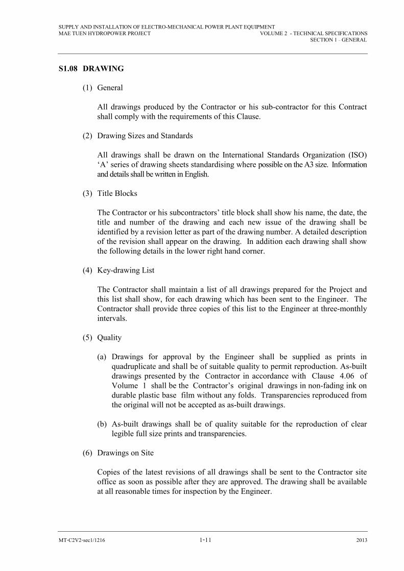
S1.08 DRAWING (1) General
All drawings produced by the Contractor or his sub-contractor for this Contract shall comply with the requirements of this Clause.
(2) Drawing Sizes and Standards
All drawings shall be drawn on the International Standards Organization (ISO) ‘A’ series of drawing sheets standardising where possible on the A3 size. Information and details shall be written in English.
(3) Title Blocks
The Contractor or his subcontractors’ title block shall show his name, the date, the title and number of the drawing and each new issue of the drawing shall be identified by a revision letter as part of the drawing number. A detailed description of the revision shall appear on the drawing. In addition each drawing shall show the following details in the lower right hand corner.
(4) Key-drawing List
The Contractor shall maintain a list of all drawings prepared for the Project and this list shall show, for each drawing which has been sent to the Engineer. The Contractor shall provide three copies of this list to the Engineer at three-monthly intervals.
(5) Quality (a) Drawings for approval by the Engineer shall be supplied as prints in
quadruplicate and shall be of suitable quality to permit reproduction. As-built drawings presented by the Contractor in accordance with Clause 4.06 of Volume 1 shall be the Contractor’s original drawings in non-fading ink on durable plastic base film without any folds. Transparencies reproduced from the original will not be accepted as as-built drawings.
(b) As-built drawings shall be of quality suitable for the reproduction of clear
legible full size prints and transparencies. (6) Drawings on Site
Copies of the latest revisions of all drawings shall be sent to the Contractor site office as soon as possible after they are approved. The drawing shall be available at all reasonable times for inspection by the Engineer.
SUPPLY AND INSTALLATION OF ELECTRO-MECHANICAL POWER PLANT EQUIPMENT MAE TUEN HYDROPOWER PROJECT VOLUME 2 - TECHNICAL SPECIFICATIONS
SECTION 1 – GENERAL
MT-C2V2-sec1/1216 �-�� 2013
(7) Position Reference
Drawings indicating the position of any item of equipment shall use the system of grid lines and levels established by the Engineer as the reference datum.
S1.09 PACKING
(1) All Plant shall be effectively protected against damage and corrosion during transportation from the place of manufacture to the site and during storage.
(2) Immediately upon arrival at Site, the Contractor shall arrange for all packages to
be checked against the shipping list for loss and inspected for damage during transit.
(3) The Department will not provide covered storage at the Site. The Contractor
shall ensure that all packages are suitable for the storage conditions provided. (4) If machined surfaces show sign of damage on receipt of shipment, the corrosion
protection shall be removed, the rust and moisture eliminated, the defects repaired by approved means and the protection re-applied.
(5) Electrical insulation shall be protected against sweating and entry of dust during
transportation and storage. (6) Flange faces and openings shall be covered by metal blanks and gaskets. Rubber
parts shall be protected against light and air. An approved drying agent shall be included with all items enclosed in plastic or other impervious material.
(7) All packing material, except that required for storage of spare parts, shall remain
the property of the Contractor and shall be removed from the Site. Only parts for immediate use shall be delivered from the works storage area and their packing material shall be removed quickly from the installation site and disposed of to the satisfaction of the Engineer.
(8) All packages shall be clearly and indelibly marked with the dimensions, weight,
slinging and load beating points. Any packages which are not symmetrically loaded shall be marked with the position of the center of gravity.
(9) Each package shall contain a packing list in a waterproof envelope. Two copies of
the packing list shall be sent to the Engineer prior to dispatch. (10) The Engineer shall reserve the right to inspect and approved the equipment and
the packing before the items are dispatched. Such inspection will not relieve the Contractor from responsibility for any loss or damage occurring during transportation and storage.

SUPPLY AND INSTALLATION OF ELECTRO-MECHANICAL POWER PLANT EQUIPMENT MAE TUEN HYDROPOWER PROJECT VOLUME 2 - TECHNICAL SPECIFICATIONS
SECTION 1 – GENERAL
MT-C2V2-sec1/1216 �-�� 2013
S1.10 PHOTOGRAPHS (1) The Contractor shall keep photographic records of the work during manufacture,
factory assembly, delivery, erection, commissioning and rectification and as required by the Engineer.
(2) The Contractor shall supply photographs which will:
(a) assist in training people , who may have no experience, in the operation, routine maintenance, major maintenance and testing of the plant; and
(b) record information which it may not be possible to obtain at a later date; and (c) record details of how work, which is not frequently required, is done. This will supplement the detailed instructions provided in the operation and maintenance instructions and reduce the need to rely on memory.
(3) A volume of photographs shall be included with the operation and maintenance
instructions. They shall be adequately edited and provided with captions and descriptions to the satisfaction of the Engineer.
(4) All costs in this connection shall be included in the Contract Price. S1.11 LABELS (1) Labels (a) The Contractor shall provide labels in sufficient numbers, size and detail to
permit rapid and positive identification to be made of all pieces of equipment whether enclosed in cubicles or separately mounted.
(b) Labels used indoors shall be engraved on double sided, engraving grade
plastic laminate with black letters not less than 3.0 mm. high on a white background. Labels (used outdoors) shall be of matt stainless steel , with the letters filled with a suitable wax (Gravograph or equal). Pipe labels shall use adhesive markers. Labels over 100 mm. long and all labels fixed outdoors shall be fastened by nickel-plated brass screws. Indoor plastic laminate labels of length less than 100 mm. shall be fastened by means of an approved contact adhesive. Labels for cubicles and equipment mounted within 2.0 m above floor level shall be positioned so that they can by read be a person of average height standing in front of the cubicles.
(c) Labels for devices mounted on or in enclosures shall be provided on the
inside of the enclosure adjacent to the device as well as on the device. Device labels shall not be located on removable covers of the device.

SUPPLY AND INSTALLATION OF ELECTRO-MECHANICAL POWER PLANT EQUIPMENT MAE TUEN HYDROPOWER PROJECT VOLUME 2 - TECHNICAL SPECIFICATIONS
SECTION 1 – GENERAL
MT-C2V2-sec1/1216 �-�� 2013
(d) Warning labels shall be provided on or in all electrical equipment where terminals at voltages of 220 V and above may be exposed during maintenance, indoor warning labels shall be of plastic laminate with white lettering on a red background. Outdoor warning labels shall be of vitreous enameled steel with white lettering on a red background.
(e) The text of each device label shall include the device number and a clear
description of the function. Fuses, miniature circuit-breakers and links shall be identified by their function, voltage, polarity, phase color and fuse link (or circuit-breaker) rating. The wording for labels shall be in the English language.
(2) Rating Plates
A rating plate complying with the requirements of the appropriate standard shall be provided on each item of plant. Where the rating plate is affixed to and item of plant of a mass in excess of 1 ton, it shall also specify the mass of the item.
(3) General
Failure to complete the supply and fixing of labels and rating plates shall be sufficient reason for the Engineer to withhold the issuing of a Provisional Acceptance Certificate in accordance with the Conditions of Contract.
S1.12 PAINTING Synthetic resin paint shall be used for the finish paint of all exposed portions of all the
Equipment, except for the portion embedded in concrete, machined mating surfaces and galvanized surfaces.
The primary coat shall be of the kind matching the finish paint mentioned and shall be
of rust preventive nature. The exposed portions of all Equipment except those embedded in concrete shall
receive shop finishes as detailed in this section. Paints shall be applied only to surfaces which are free of moisture as determined by
sight and touch. The ambient temperature shall be at least 5̊C above the minimum temperature recommended by paint supplier for application on any coat.
The paint shall be applied using brush or spray techniques. When painting on any surface
has commenced, the painting operation shall be completed as soon as practicable, without delays. The drying time between coats shall not be less than 12 hours.
The Contractor shall supply touchup paint to match all shop-painted items. This quantity shall
be at least 15 percent of the paint used to the original shop painting, except for the control cubicles for which at least 30 percent of the original quantity of paint shall be supplied.

SUPPLY AND INSTALLATION OF ELECTRO-MECHANICAL POWER PLANT EQUIPMENT MAE TUEN HYDROPOWER PROJECT VOLUME 2 - TECHNICAL SPECIFICATIONS
SECTION 1 – GENERAL
MT-C2V2-sec1/1216 �-�� 2013
The color schedule for the Equipment will be decided by Munsell color notation and included in the Award of the Contract.
The painting system referred to in these Specifications shall be as follows:- PAINT SYSTEM 1 Surfaces in Contract with Water (a) General
All surfaces shall be painted with an inorganic, epoxy zinc-rich primer and three coats of coal tar epoxy. Final shop painting shall not be applied within 100 mm of field welding. These areas will only receive one coat of inorganic, epoxy zinc - rich primer that can be removed prior to welding.
(b) Surface Preparation Surfaces shall be blast-cleaned in accordance with SSPC-SP10. (c) Paint Application (i) Materials
The painting system shall consist of one coat of inorganic, epoxy zinc-rich primer and three coats of a compatible coal tar system.
All components shall be from the same supplier and the supplier’s instructions shall be rigidly adhered to.
(ii) Film Thickness
The dry film thickness of the primer shall be between 0.05 mm and 0.09 mm. The dry film thickness of each of the coal tar epoxy coats shall be between 0.15 mm. and 0.20 mm.
(d) Final Film Thickness
The final thickness of the three coats shall be at least 0.45 mm. This shall be checked by a Type B film thickness gauge, supplied by the Contractor, calibrated on metal identical in composition, thickness and surface preparation and finish to that being painted. A sufficient number of measurements shall be made to establish the final thickness.
The entire painted surface shall be subject to electrical inspection by a holiday detector, furnished by the Contractor.
SUPPLY AND INSTALLATION OF ELECTRO-MECHANICAL POWER PLANT EQUIPMENT MAE TUEN HYDROPOWER PROJECT VOLUME 2 - TECHNICAL SPECIFICATIONS
SECTION 1 – GENERAL
MT-C2V2-sec1/1216 �-�� 2013
PAINT SYSTEM 2 Surfaces in Contact with oil (a) Surface Preparation Surface shall be blast-cleaned in accordance with SSPC-SP10. (b) Paint Application (i) Materials
The painting system shall consist of two coats of a high built epoxy paint suitable for this purpose.
(c) Final Film Thickness
A sufficient number of readings with a gauge supplied by the Contractor shall be taken to ensure a minimum dry film thickness of 0.30 mm. is attained.
PAINT SYSTEM 3 Electrical Panels and Boards (a) Surface Preparation Surfaces to be painted shall be blast-cleaned in accordance with SSPC-SP6. (b) Paint Application (i) Materials
The painting system shall comprise two coats of inorganic, zinc-chromate primer and two coats of epoxy enamel.
(ii) Film Thickness
The dry film thickness of the primer shall be not less than 0.80 mm. and the dry film thickness of the epoxy enamel shall be not less than 0.10 mm.
(c) Final Film Thickness
A sufficient number of readings with a gauge supplied by the Contractor shall be taken to ensure that a minimum final film thickness of 0.25 mm. is attained.

SUPPLY AND INSTALLATION OF ELECTRO-MECHANICAL POWER PLANT EQUIPMENT MAE TUEN HYDROPOWER PROJECT VOLUME 2 - TECHNICAL SPECIFICATIONS
SECTION 1 – GENERAL
MT-C2V2-sec1/1216 �-�� 2013
PAINT SYSTEM 4 (FOR INDOOR STEEL WORK) Mechanical Equipment, Prefabricated Piping (a) Surface Preparation Surfaces to be painted shall be blast - cleaned in accordance with SSPC - SP10. (b) Paint Application (i) Materials
The painting system shall comprise one coat of inorganic epoxy zinc-rich primer and two finish coats of acrylic latex, glossy finish paint.
(c) Final Film Thickness
A sufficient number of readings with a gauge supplied by the Contractor shall be taken to ensure a minimum film total thickness of 0.30 mm. is attained.
METAL COATINGS (a) Galvanizing shall be applied by the hot-dip process to ASTM A120, ASTM A123
and ASTM A153. Materials (such as welding slag, paint and grease) likely to resist attack by the pickling liquid shall be removed prior to pickling. The surface after galvanizing shall carry an unbroken covering of zinc uniform in appearance and in thickness. The thickness shall be 0.09 mm. (0.6 kg/m2.)
(b) Electroplating shall be either nickel plus chromium plating, cadmium plating or
zinc plating shall comply with the following: (i) Nickel plus chromium plating shall be in accordance with ASTM B456.
Nickel plating alone shall not be used. (ii) Electroplating of zinc shall be in accordance with ASTM B633 and ASTM A164.
S1.13 LOCKING FACILITIES (1) Where locking facilities are required to prevent unauthorized access to or
operation of equipment, the facility shall be suitable of application of a padlock with 10 mm. shackle diameter and 35 mm. shackle opening.
(2) Integral locking facilities, e.g., of the key-in handle type will not be accepted and if
normally fitted in proprietary equipment shall be removed or otherwise rendered inoperative.

SUPPLY AND INSTALLATION OF ELECTRO-MECHANICAL POWER PLANT EQUIPMENT MAE TUEN HYDROPOWER PROJECT VOLUME 2 - TECHNICAL SPECIFICATIONS
SECTION 1 – GENERAL
MT-C2V2-sec1/1216 �-�� 2013
S1.14 TROPICALIZATION (1) General : All materials and equipment supplied under these Specifications shall be
suitable for being delivered, stored and operated under tropical conditions of high temperature, high humidity, heavy rainfall, mildew and fungus conductive environment.
Process for tropicalization shall be in accordance with the best commercial and industrial practices.
(2) Metals : Iron and steel shall generally be painted of galvanized or metal-sprayed
as appropriate. Indoor parts may alternatively have chromium or copper-nickel plantings, or other suitable protective finish. When it is necessary to use dissimilar metals in contacts, these shall so selected that the potential difference between them in the electrochemical series is not such as to cause galvanic corrosion. If this is not possible, the contact surface of one both of the metals shall be electro-plated or otherwise finished in such a manner that the potential difference is reduced within the required limits or, alternatively, the two metals shall be insulated from each other by a suitable insulating material or a coating of varnish compound.
(3) Bolts, Screws, Nuts, Washers: Steel bolts, screws, nuts and washers when used,
shall be zinc, cadmium or chromium plated or, where plating is not possible due to tolerance limitations, of corrosion-resisting steel. All wood screws shall be dull nickel-plated brass or of other suitable finish. Corrosion-resisting steel, copper-nickel alloy or bronze, shall also be used for bolts and nuts when either or both are subject to frequent adjustment or removal, or are in contact with water and for bolts projecting from concrete with nuts to removal or vice versa.
(4) Fabrics, Cork, Paper, etc.: Fabrics, cork paper and similar materials, which are
not subsequently protected by impregnation, shall be adequately treated with suitable fungicide. Sleeve and fabrics treated with linseed oil varnishes shall not be used.
(5) Adhesives: Adhesives shall be especially selected to ensure the use of types
which are impervious to moisture, resistant to mold growth and not subject to the ravages of insects. Synthetic resin cement only shall be used for joining wood. Case in cement shall not be used.
(6) Electrical Material and Equipment : Materials and components which are
inherently fungus resistant or are protected by hermetic sealing or oil immersion need not be treated. Other elements shall be protected by additional varnish for high humidity and given an antifungal treatment.

SUPPLY AND INSTALLATION OF ELECTRO-MECHANICAL POWER PLANT EQUIPMENT MAE TUEN HYDROPOWER PROJECT VOLUME 2 - TECHNICAL SPECIFICATIONS
SECTION 1 – GENERAL
MT-C2V2-sec1/1216 �-�� 2013
S1.15 MISCELLANEOUS METALWORK The Contractor shall provide and install in respect of the Plant in his supply, the
following miscellaneous metalworks; (a) Soleplates, bedplates, foundation bolts and anchor bolt; (b) Floor plates and kerbing, including covers for pipe and cable trenches, required for
completing the floors around and over the Plant; (c) Platforms, stairways, ladders, guards, handrails necessary for easy and safe access
to the Plant requiring access for operation, maintenance and testing; (d) Safety guards at each point where normal access would permit personnel to come
with in reach of any moving item of plant; and (e) Lifting lugs, eyebolts or other lifting attachment points on each item having a
mass of more than 40kg. S1.16 EMBEDMENT, FOUNDATIONS AND PLINTHS
(1) (a) Except where otherwise stated, embedded supports and other embedded metalwork shall be provided by the Contractor. They shall be consistent with dimensioned concrete outline and structural metalwork drawings. The Contractor shall ensure that adequate provision has been made in the civil drawings for the complete installation of his Plant and shall inform the contractor for the civil works of:
(i) Any required changes and the reasons; (ii) Location and outlines of all metalwork to be embedded in the concrete. (b) Any equipment to be embedded shall be supplied to the civil works contractor
not less than 3 months before construction work is programmed to commence in the area concerned.
(c) Unless the Contractor informs the civil works contractor of his requirements
not less than 3 months before work is programmed to commence in the area concerned , such additions or alternations to the civil works shall be made by the Contractor or, if the Engineer so requires, by the Department at the expense of the Contractor.
(d) The Contractor shall be responsible for ensuring that any items which he
requires to have embedded and any agreed alterations to the civil works, are carried out on site.

SUPPLY AND INSTALLATION OF ELECTRO-MECHANICAL POWER PLANT EQUIPMENT MAE TUEN HYDROPOWER PROJECT VOLUME 2 - TECHNICAL SPECIFICATIONS
SECTION 1 – GENERAL
MT-C2V2-sec1/1216 �-�� 2013
(2) All scrabbling to a depth of 15 mm grouting in of plant, grillages and steelwork, adjustment to foundation levels, grinding of foundations, bedding on foundations and cementing into walls and floors, shall be carried out by the Contractor.
(3) Equipment for mounting on floors shall be installed on concrete plinths to be
constructed by the Contractor with the finished level up to 75 mm above the floor level to cater for normal variations which will occur in foundations. With respect to his Plant, the Contractor shall supply all foundation bolts and packing plates between the concrete and the plant, equipment and bases.
(4) Plant which is mounted on the floor and which does not require supporting
steelwork grouted or embedded in the concrete foundation and plant which is surface mounted on concrete walls or the lower face of concrete shall be fixed in position by approved masonry anchors. Masonry anchors shall be expansion type or resin adhesive type, shall be of adequate strength and corrosion-proof. The Contractor shall provide the fastenings and shall forward to the Engineer full details of the proposed masonry anchors including typical pull-out values and if requested shall submit samples for approval. Wooden, fiber of plastic plugs or similar type fixings will not be accepted.
(5) Embedded parts installed by the Contractor shall be accurately placed and secured
by the Contractor. The placing of the concrete around such items will be by others.
S1.17 POSITION OF INSTRUMENTS, CONTROLS AND HANDWHEELS (1) Instruments shall be located conveniently for access and reading. Instruments
which must be read frequently shall be located between 750 mm and 1,800 mm from the floor. Those which are read occasionally may be located between 500 mm and 2,000 mm from the floor.
(2) Controls and valve hand wheels shall be located conveniently for access and
operation. In general controls should be within the range 750 mm to 1,500 mm and valve hand wheels 1000mm to 500mm above floor level.
S1.18 FABRICATION AND WELDING
(1) General Requirements for Fabrication
The following requirements shall apply to all fabrication of components. (a) Plates and sections shall be free of all surface marks or damage exceeding 1 mm
deep. (b) Weld root gaps for partial penetration welds shall not exceed 1.5mm the
dimensions of weld preparations, root gaps and plate alignment shall be to

SUPPLY AND INSTALLATION OF ELECTRO-MECHANICAL POWER PLANT EQUIPMENT MAE TUEN HYDROPOWER PROJECT VOLUME 2 - TECHNICAL SPECIFICATIONS
SECTION 1 – GENERAL
MT-C2V2-sec1/1216 �-�� 2013
tolerances specified on the relevant drawings. All weld preparations shall be subject to examination for material flaws.
(c) Before welding, the weld preparation and plate surface for 15 mm on either
side of the preparation shall be completely cleaned to base metal including complete removal of any surface coating be abrasive blasting.
(d) Weld procedure and welder qualification tests shall be carried out in
accordance with the approved standards. Where the standard does not specifically require weld procedure and/or welder qualification test, the Engineer may require the Contractor to submit details of the proposed weld procedure and of the qualifications of the proposed operator. The Engineer may at his discretion require that weld procedure and/or welder qualification tests be conducted in such cases. The Engineer reserves the right to call for further qualification tests and to withdrawn approval of any welder whose work is unseat is factory.
(e) Weld procedure and welder qualification tests shall reproduce the production
conditions including preheat, electrode treatment, interpass temperature, degree of restraint and stress relief.
(f) Undercut not exceeding 1 mm. deep shall be removed by grinding; undercut
exceeding 1 mm. deep shall be filled by welding. (g) The surface of welds shall be smooth and free of sharp contour changes. The
Contractor shall grind the surface of any weld as necessary in the opinion of the Engineer to avoid affecting the interpretation of non-destructive examination.
(h) Arc strikes on the place surface shall be avoided. Accidental are strikes shall
be ground out and the area crack-detected. (i) Welded-on fabrication aids shall be kept to a minimum and shall be
subject to the approval of the Engineer. They shall be attached only by approved welders using approved procedures and shall be removed by flame cutting not less than 1.5 mm above the parent plate surface and then by subsequent grinding and crack-detecting of the weld area.
(j) Butt welds shall be free from under filling and from reinforcement greater than
one-tenth the face width of the weld. All undercut shall be filled by welding. (k) Wherever practicable, welding shall be carried out in the down hand position.
(l) Weld spatter shall be completely removed. Machined surfaces and tapped
holes shall be adequately protected from spatter during welding.

SUPPLY AND INSTALLATION OF ELECTRO-MECHANICAL POWER PLANT EQUIPMENT MAE TUEN HYDROPOWER PROJECT VOLUME 2 - TECHNICAL SPECIFICATIONS
SECTION 1 – GENERAL
MT-C2V2-sec1/1216 �-�� 2013
(m) Joints not completely protected from the weather or in a corrosive environment shall be seal welded. Unless otherwise approved, welds between dissimilar metals shall be performed at the Contractor’s premises.
(n) Electrodes shall be stored and dried before use strictly in accordance with the
electrode manufacturer’s recommendation and welding code requirements.
(o) Preheat and interpass temperatures shall be applied in accordance with the electrode and steel manufacturer’s recommendation and with the weld procedure tests. Measurements shall be by temper sticks or surface pyrometer on the opposite side of the plate surface pyrometer on the opposite side of the plate surface from that to which heating is being applied.
(2) Further Requirements for Important Stressed Components
The important stressed components shall mean those components whose failure would endanger the operation of plant or the safety of personnel. They shall include but shall not necessarily be confined to:
(a) Components or parts there of including welds which are stressed to greater
than 40 percent of yield stress in normal or abnormal service conditions; (b) Components which are stressed directly or indirectly be pressure conduit or
tailwater pressure, operating oil pressure or air pressure; (c) All rotating parts of main plant (generator and turbine but excluding
auxiliaries); (d) Bearings and their support systems; and (e) Lifting equipment, crane girders and crabs.
The following further requirements shall apply to the important stressed components in addition to the requirements in sub-clause (1) of this Clause.
(i) All plate materials and sections shall be identified by heat number at all phases of fabrication and erection. They shall be checked ultrasonically for internal defects.
(ii) As far as practicable, all shop-welded fabrication shall be stress relieved. (iii) As far as practicable, all welds shall be full penetration, back-gouged and
of a configuration which lends itself to radiographic or ultrasonic examination.
(3) Non-destructive Testing of Welds in Steel Components (a) All full penetration welds in important stressed components shall be
examined for their full length radiographically or ultrasonically. In general this examination shall be by radiography for butt welds and by ultrasonic for
SUPPLY AND INSTALLATION OF ELECTRO-MECHANICAL POWER PLANT EQUIPMENT MAE TUEN HYDROPOWER PROJECT VOLUME 2 - TECHNICAL SPECIFICATIONS
SECTION 1 – GENERAL
MT-C2V2-sec1/1216 �-�� 2013
tee-welds. The examination methods and the standard of acceptability shall be in accordance with Section V of the ASME Code.
(b) In addition a percentage of all other welds shall be examined ultrasonically or
radiographically. The examination methods, extent of examination and standard of acceptability shall be in accordance with Section V of the ASME Code or AWS Code.
(c) The toes of all fillet welds in important stressed components shall be subject
to crack-detection. (d) Radiography of welds shall be carried out in accordance with Section V of the
ASME Code. (e) The Contractor shall submit radiographs and reports to the Engineer within 7
calendar days of the taking of radiographs. The report shall contain complete identification of the component concerned, definition of the location of the radiographed areas, full description of the radiographic techniques and report on all indications of the film.
(f) Ultrasonic techniques and acceptability of defects found by ultrasonic
examination shall be in accordance with ASTM A435. (g) Welds in which unacceptable defects are found by radiography or ultrasonic
examination shall be subject to re-examination by the same respective method after repair.
(4) Non-destructive Testing of Welds in Aluminum Components
Such welds shall be tested generally in accordance with Section V of the ASME Code. The actual scope of tests shall be to the approval of the Engineer, dependent on the design and function of the components concerned.
S1.19 PIPING, VALVES AND THREADED FASTENERS (1) General: All piping , valves and threaded fasteners shall be designed according to
ANSI Standards; the pipes shall be in accordance with ANSI B 31.1; all flanges shall be of raised face (RF) designed according to ANSI B 16.5.
Screwed joints may be used for pipes up to 50 mm. diameter at working pressures not exceeding 7 kg/cm2. Pipes of 25mm. diameter and less for working pressures exceeding 7 kg/cm2 shall be joined by unions of approved type.
The working pressure of a system shall be taken as the maximum pressure it can attain including water hammer and/or relief valve blow-off pressure.

SUPPLY AND INSTALLATION OF ELECTRO-MECHANICAL POWER PLANT EQUIPMENT MAE TUEN HYDROPOWER PROJECT VOLUME 2 - TECHNICAL SPECIFICATIONS
SECTION 1 – GENERAL
MT-C2V2-sec1/1216 �-�� 2013
The pipe diameters shall be calculated considering the following maximum allowable speeds:
Air 15 m/s and 5 m/s in between compressors and receivers; Oil and water at the suction side m/s; Oil and water at the pressure side 2.5 m/s.
The thicknesses of the pipes shall be calculated following the ANSI requirements; at least 3 (three) millimeters for corrosion shall be considered for the water and air piping and 1 (one) millimeter for the oil piping.
All piping 100 mm nominal diameter and larger shall be completely prefabricated at Contractor’s workshop with all fittings in place except that extra length for field cutting and welding shall be provided where required for field assembly. Piping with flanged connections shall be furnished with gaskets, bolts, studs and nuts. All pipes up to 50 mm nominal diameter shall be assembled by means of threaded or socket welded fittings. Threaded and socket welded pipe will be Site fabricated, as erection proceeds.
Piping systems shall be complete with fittings, valves, supports and all necessary accessories. Piping arrangement shall be neat in appearance and shall allow a convenient operation. Items requiring periodic attention shall be easily and readily accessible from floors or platforms. Pipes shall neither obstruct passways nor interfere with access to valves and equipment. The piping buried in the concrete shall be sloped for drainage and provided with 25 mm diameter drain valves at all low points in the system.
The supports, hangers, anchors and clamps necessary to support and restrain all pipes and valves shall be designed, selected and located in order to ensure uniform continuous slopes for draining and minimize stresses in the piping material, and to let the piping system be safely supported, guided and anchored especially for the pipes to be laid in the pier trench.
All items to be site welded to the piping shall be of the same material as that of the relevant piping.
As far as practicable, the supports shall be grouped and of consistent design throughout.
The Contractor shall submit for approval drawings showing;
The piping flow diagram; The piping P and I diagram; The piping layouts.
SUPPLY AND INSTALLATION OF ELECTRO-MECHANICAL POWER PLANT EQUIPMENT MAE TUEN HYDROPOWER PROJECT VOLUME 2 - TECHNICAL SPECIFICATIONS
SECTION 1 – GENERAL
MT-C2V2-sec1/1216 �-�� 2013
The Contractor’s calculations of the piping diameters and thickness shall be available for approval at the Engineer’s request.
Asymmetric sketches shall be supplied for site erection. (2) Pipes: Pipes shall be in accordance with the ASTM A 53 Grade B standard
specification or approved equivalent for welded and seamless steel pipe. Type S, seamless pipes will be preferred. Longitudinal welded pipes type E, electric resistance welded pipes are subject to approval.
All pipes shall be shipped with the ends plugged by plastic covers.
The beveled ends to be welded at site shall be protected by a special paint compatible with the welding.
Elbows having radius at least 1.5 nominal diameter shall be used for changes in the direction of piping having 75 mm nominal diameter and over. For piping having 50 mm. nominal diameter and below commercial fittings shall be used. Bends having radius not less than 5 nominal diameter instead of ells may be used.
Minimum wall thickness at any point of the elbows, bends and ells shall not be less than the minimum wall thickness allowed for pipes. Shop prefabricated pieces may be employed for tee reducers, drain and other special pieces. Materials and thickness shall be the same as for the straight pipe. |Branch connections shall be reinforced where necessary in accordance with the requirements of ANSI B 31.1 “Code for Pressure Piping” For piping having 50 mm. nominal diameter and over, seamless type fittings such as tee, reducers and cap shall be used for intersection of piping, piping branches, changes in size and end closure. Metered fittings and metered bends will not be accepted.
(3) Valves: All the valves shall be of the flanged type, made of carbon steel with
stem and sealing rings of stainless steel; all valves shall be provided with back seated items.
Valves nominal diameter shall always be equal to the relevant pipe diameter.
Seals and seats shall be positively fixed so that they cannot become loose in service. The fixing of seals and seats by an interference fit only is not acceptable.
The operating mechanism shall have means of lubrication and position indicators and, in the case of isolating valves, the means of padlocking in the open and closed positions together with approved padlocks and keys.
All hand-operated valves shall close by clockwise rotation of the hand wheels which shall be marked to show the direction of closing. Valve hand wheels shall be located for safe and convenient operation with extended spindles where necessary to achieve this. All hand operated valves shall be capable of being

SUPPLY AND INSTALLATION OF ELECTRO-MECHANICAL POWER PLANT EQUIPMENT MAE TUEN HYDROPOWER PROJECT VOLUME 2 - TECHNICAL SPECIFICATIONS
SECTION 1 – GENERAL
MT-C2V2-sec1/1216 �-�� 2013
opened and closed against their maximum working pressure fully unbalanced with a force at the hand wheel not exceeding 100 N. If necessary to achieve this, reduction gearing, ball or roller bearings shall be provided.
As far as practicable, all valves for similar service shall be of the same make and type and be interchangeable.
All gate valves for water and air service shall be of a type in which the operating mechanism is not subject to the working fluid.
Valves other than needle type shall not be used permanently if the need for throttling is foreseen, such as to adjust flow subdivision in a system, orifice plates or needle valves with fixed stops shall be provided.
Valves for water and oil service may be gate, butterfly, ball, plug or needle type, whichever is most suitable to the particular service and operating pressure. Valves for air service may be ball, plug or needle type whichever is most suited to the particular service.
Non-return valves shall be of a type specifically designed to avoid impact and water hammer on closure. The closing member shall be pivoted from the valve body, not from a lid cover.
Relief valves for pumps shall be of direct spring loaded, angle body type.
For identification each valve of 150 mm. N.D. and over shall be provided with stainless steel identification disc on the hand wheel.
On this disc the following shall be etched:
manufacturer; catalogue number; size inches; rating and fluid; trim material; body and bonnet material. Valves below 150 mm. N.D. shall be identified with size and ANSI class. The disc shall be written in English.
(4) Threaded Fasteners: The threaded fasteners shall comply with ISO metric system
and with the following requirements:
steel bolts shall be forged unless otherwise approved; mild steel fasteners shall be zinc or cadmium plated;

SUPPLY AND INSTALLATION OF ELECTRO-MECHANICAL POWER PLANT EQUIPMENT MAE TUEN HYDROPOWER PROJECT VOLUME 2 - TECHNICAL SPECIFICATIONS
SECTION 1 – GENERAL
MT-C2V2-sec1/1216 �-�� 2013
all parts shall be spot-faced or machined for nuts or bolts except in the case of clearance bolts in structural steelwork;
tapped holes shall not be used in sheet metal less than 6 mm. thick; fasteners of less than 6 mm. diameter shall not be used except in instruments and
relays; threaded fasteners of more than 8 mm. diameter shall have hexagon or socket
hexagon heads; all threaded fasteners subject to vibrations and/or installed in a position which is
unable to be inspected during operation shall be locked in an approved manner. S1.20 CASTING AND PATTERNS (1) All steel castings shall be annealed in accordance with the relevant standard. All
iron castings shall be mild annealed in a suitable annealing furnace to relieve casting strain before being machined.
(2) The Contractor shall retain all patterns required for the production of the Plant at
least until the end of the maintenance period. S1.21 LUBRICATION (1) The Contractor shall submit, for the approval of the Engineer, a complete list of
the lubricants recommended for each part of the Plant; this list shall give the type and grade of each lubricant in sufficient detail to permit the correct lubricant to be supplied from normal commercial domestic sources. As far as possible the number of different types of lubricant required for the plant shall be reduced to a minimum.
(2) All lubricants and flushing oils required for the plant up to the time of taking over
shall be provided by the Contractor. (3) The Contractor shall nominate a minimum number of standard size grease nipples
which shall be used for all Plant. (4) The filling points for lubricating oil systems shall be provided with fine gauze
filters beneath the filling caps to prevent the entry of dust. (5) Drip trays shall be provided beneath oil filling and drain points and any other
locations subject to oil leakage or spillage. (6) The filling and drainage points shall be located so that they are conveniently
accessible. Adequate working space shall be provided for the positioning of buckets, hoses and other appliances used for filling and drainage.

SUPPLY AND INSTALLATION OF ELECTRO-MECHANICAL POWER PLANT EQUIPMENT MAE TUEN HYDROPOWER PROJECT VOLUME 2 - TECHNICAL SPECIFICATIONS
SECTION 1 – GENERAL
MT-C2V2-sec1/1216 �-�� 2013
S1.22 SELF-LUBRICATING BUSHES (1) Where self-lubricating bushes are specified, they shall be as follows: (a) For applications subject to immersion or to weather, - bronze with lubricating
insert (‘Lubrite’ by Merriman, Hingham USA or equivalent). The lubricant shall have long-term resistance to deterioration when exposed to atmosphere and water in a tropical climate.
(b) For indoor, nominally dry application - as in paragraph (a) of this sub-clause
or epoxy resin with glass mesh reinforcement and hard chromium plated and ground journals.
(2) The use of ‘Teflon’ or similar materials and the use of materials which promote
electrochemical action, is not acceptable. S1.23 TEST, GENERAL REQUIREMENTS (1) Test During Manufacture-General: (a) All Plant materials and components shall be subject to type, sample and
routine tests and inspection while in the process of and upon completion of manufacture at the Contractor’s premises in accordance with this Specification and the Conditions of Contract. Tests listed in the Standards as optional tests (to be performed if specified at the time of ordering) are required to be performed unless otherwise stated.
(b) The Department, its representative and/or the Engineer will visit the factory of
the Contractor during manufacturing and factory tests. The attendance to the Contractor’s factory for any purpose by The Department, its representative and/or the Engineer shall not in any way release the Contractor of any of his obligations under the Contract until the final acceptance certificate is issued. Some factory tests, if so permitted by prior approval of the Engineer, may be performed without the presence of The Department, its representative and/or the Engineer.
(c) The Contractor shall bear the cost for receiving the following engineers from
the Department for a period of one (1) month each, which shall include round-trip economy class air fare from Bangkok to the factory, local transportation cost, lodging and meals and other miscellaneous expenses necessary for the purpose of the trip. The costs for receiving the Department’s engineers at the Contractor’s factory shall be included in the prices bid in the Schedules.
(i) for turbines two (2) engineers (ii) for generators two (2) engineers (iii) for associated equipment two (2) engineers

SUPPLY AND INSTALLATION OF ELECTRO-MECHANICAL POWER PLANT EQUIPMENT MAE TUEN HYDROPOWER PROJECT VOLUME 2 - TECHNICAL SPECIFICATIONS
SECTION 1 – GENERAL
MT-C2V2-sec1/1216 �-�� 2013
(d) It is the intention of the Department. to acquire the services of a qualified inspection company to conduct expediting services, inspection company to conduct expediting services, inspection during manufacture and attendance at factory tests. The Contractor is required to provide all reasonable facilities including advance notice (at least thirty (30) days) of all testing dates in order that the said inspection company may fulfill all of its duties as required under the contract to be made between the Department and the inspection company. The attendance of the inspection company at the Contractor’s factory during fabrication and at factory tests shall not relieve any of the obligations of the Contractor under this Contract.
(e) Type, sample and routine tests shall be to the relevant American Standards or
other approved standards for equipment where the test requirements are not specified in this Specification.
(f) The Contractor may offer type test results for identical equipment in lieu of
the type tests specified, in which case the specified type tests may be waived by the Engineer. If type test results for identical equipment are offered in lieu of the specified type tests, the Contractor shall also provide evidence as to the similarity of the equipment tested and the Contract Plant.
(g) The Contractor shall submit evidence to the Engineer that the instruments
used for the tests have been calibrated at an approved testing laboratory within a period of up to 3 months for a portable instrument and 6 months for a fixed instrument.
(h) The Contractor shall submit to the Engineer 4 certified copies of all results of
all tests required under the Contract. The results of each test shall be recorded in the form of test certificates or test reports.
(i) The results of tests shall be submitted to the Engineer within 1 month of the
tests being carried out. (j) In the event of any test piece failing to comply with the requirements of the
Contract, the Engineer may reject the whole of the material represented by the test piece.
(2) Tests at Site - General (a) Responsibility for Tests (i) The Contractor shall conduct the Tests at Site (ii) The Contractor shall provide everything required to carry out the tests,
including the provision, installation and removal of all test instruments and obtaining of all records. The Contractor shall provide certified test certificates to prove that all instruments have been calibrated by an approved laboratory not more than 3 months prior to carrying out the

SUPPLY AND INSTALLATION OF ELECTRO-MECHANICAL POWER PLANT EQUIPMENT MAE TUEN HYDROPOWER PROJECT VOLUME 2 - TECHNICAL SPECIFICATIONS
SECTION 1 – GENERAL
MT-C2V2-sec1/1216 �-�� 2013
tests. The Contractor must specify items of testing equipments to be handed over to the Department.
(iii) The Contractor shall prepare and submit the program to the Engineer for approval, schedules for each test together with a program for the Tests on Completion.
(iv) The Contractor shall submit one copy of the results of each of the Tests at Site to the Resident Engineer at Site within one week of the tests being carried out. Four copies of the certified results of each of the Tests at Site in the form of test reports or test certificates shall be provided to the Engineer within one month of the tests being carried out.
(v) The Department’s staff may observe or participate in the Tests on Completion.
(b) Scope of Tests
The Tests at Site to be carried out and passed before taking over of the Works by the Administration shall be deemed to comprise two main stages of testing as follows:
(i) Preliminary tests which are tests performed prior to rotation of, energizing at normal voltage or admission of normal water or air pressure to the main or ancillary Plant under test.
(ii) The Tests on Completion which are tests to progressively prove the correct operation of complete ancillary systems and of the main Plant items.
The Tests on Completion shall include, immediately following all other tests, a test of service performance including 50 hours running. Where appropriate, the plant shall be connected to the PEA power system. The test shall include a total of 50 starting, and stopping sequences. The service performance tests shall be completed without adjustment and without fault. This shall be a prerequisite for taking-over.
S1.24 ELECTRICAL EQUIPMENT (1) Motors All motors shall be totally enclosed, fan-cooled type with provision for lubrication,
suitable for operation in high ambient temperatures and high humidity conditions. Motors up to and including 1/2 hp shall be 220 V, single-phase. The exception to this will be motors on the emergency “essential services” but that must be 380 V, 3-phase. All motors above 1/2 hp shall be 380 V, 3-phase.
Unless otherwise specified, induction motors shall be of the direct-line starting, drip-
proof type, and when operated, shall not develop trouble under a voltage fluctuation of +10 percent. The induction motors shall not be affected by a rise of 30 or 40 percent in voltage and frequency due to a full load rejection of the unit.
SUPPLY AND INSTALLATION OF ELECTRO-MECHANICAL POWER PLANT EQUIPMENT MAE TUEN HYDROPOWER PROJECT VOLUME 2 - TECHNICAL SPECIFICATIONS
SECTION 1 – GENERAL
MT-C2V2-sec1/1216 �-�� 2013
Motors shall be - normal starting torque - low starting current - squirrel-cage induction type - designed for full voltage starting - drip tight or weatherproof - totally enclosed. Would rotor motors will be acceptable only if a squirrel-cage type were not
satisfactory for the duty. The motors shall have Class B, 80oC temperature rise and continuous rating at 40oC ambient temperature and class F insulation. Motor lead insulation shall be Class B and cable terminal boxes shall be provided preferable with stud type connectors.
(2) Magnetic Motor Starters Magnetic motor starters shall have the following features and/or accessories: (a) molded case circuit breaker disconnect with thermal time delay and
instantaneous trips (b) a 380 - to 220-V individual fused control transformer (c) a 220 - V ac operating coil (d) thermal overload protection in each phase - temperature compensated with
thermal elements correctly related to motor nameplate, current and type of enclosure
(e) auxiliary contacts for the control of related auxiliary devices such as motor
heating, indicating lights, inter-locks, etc. All starters shall be suitable for across-the-line starting of motors with manual
resetting and under voltage release features. All motors of 25 hp and above shall be provided with ammeters with suppressed
scale for starting current and have motor full-load current deflection at roughly two-thirds of the scale.
All motors shall be provided with quick-break molded case circuit breakers with
operating handle lockable in OFF position. They shall be rated to interrupt the full-load current of motor or other equipment in the circuit.
Magnetic contactors used in various switches shall be made of arc-resistant
metal and have sufficient capacity against current onrush. The contacts shall be designed to obtain high contact pressure and positive seating to reduce contact bounce.

SUPPLY AND INSTALLATION OF ELECTRO-MECHANICAL POWER PLANT EQUIPMENT MAE TUEN HYDROPOWER PROJECT VOLUME 2 - TECHNICAL SPECIFICATIONS
SECTION 1 – GENERAL
MT-C2V2-sec1/1216 �-�� 2013
(3) Relays and Devices Electric contacts of dial type thermometers, thermal relays, oil level relays, oil
pressure relays, air pressure relays, limit switches, etc., shall be able to safely break a current of possible maximum inductive load (2A) and 125Vdc.
The contact surfaces (both male and female) for a transistor sheet (printed card)
shall be gold plated. All printed cards shall be suitably treated to prevent damage to connection or components by hydrogen sulfide gas.
The relays (control, protection and auxiliary relays) and meters shall be air-
sealed to prevent corrosion by hydrogen sulfide gas which will probably occur after water is impounded in the reservoir.
Mechanical targets (operated at 125Vdc) shall be individually provided with any
equipment that is annunciated as a group due to a faulty condition. In this manner the faulty equipment can be easily identified.
(4) Molded Case Circuit Breakers All molded case circuit breakers shall have 2 or 3 poles as required, having thermal
time delay and instantaneous trips with ON-TRIP-OFF indicating operating mechanisms. Circuit breakers used in conjunction with motor starters or contractors shall have the operating mechanisms interlocked with the starter or contractor cover, so that the cover cannot be opened unless the circuit breaker is open.
Circuit breakers shall be bolt-in type, interchangeable, temperature compensated,
quick-make, quick-break type and shall comply with NEMA standards. A group alarm contact shall annunciate an open breaker and each breaker shall
have an individual light which shall come on when the breaker is open. (5) Pilot Devices Pilot devices such as selector switches, push-button stations, thermostats, etc.,
shall be of the heavy duty, oil tight type, housed in a dust-tight enclosure designed especially for the type of environmental. Local stop buttons neat the motors shall be lockable in pressed position for maintenance.
(6) Indicating Lights All indicating lights shall be of LED type (E12) long life and service under
conditions of shock, vibration and rough handling unless otherwise specified. (7) Instruments and Meters All instruments and meters shall have approximately 110 mm. dials, shall be of heavy
duty industrial type, suitable for withstanding extreme shock and severe vibration.
SUPPLY AND INSTALLATION OF ELECTRO-MECHANICAL POWER PLANT EQUIPMENT MAE TUEN HYDROPOWER PROJECT VOLUME 2 - TECHNICAL SPECIFICATIONS
SECTION 1 – GENERAL
MT-C2V2-sec1/1216 �-�� 2013
(8) Convenience Outlets Convenience outlets in the control cabinets shall be duplex 3-pin type rated for 15 or
20A at 250V, suitable for Thailand pattern plug as approved by the Engineer. (9) Pressure, Level and Flow Switches The sensing switches shall have weatherproof or dustproof enclosures and shall
be mounted for easy adjustment and for rigidly cocking in position after being adjusted. They shall be of heavy duty rating and shall have stainless steel rotating parts and permanently lubricated bearings.
(10) Electrical Enclosures Unless indicated otherwise in this Specification, electrical enclosures except
junction boxes and pull boxes 4 inches trade size and smaller shall be as follows: Location Enclosure type Indoor (nonhazardous) Dry area NEMA 12 Areas where moisture conditions are more severe than those for which NEMA 12 enclosures are intend NEMA 4 Outdoor (nonhazardous) NEMA 4 Hazardous areas In accordance with the requirements of the
National Electrical Code for the location The construction of electrical enclosures located in areas subject to conditions
classified in the National Electrical Code as hazardous shall be of a type designated by NEMA as suitable for the environment in which they are located.
Electrical switchboards, panels, and cabinets, except those of cast metal, shall be
constructed from steel plate reinforced as required to provide true surface and adequate support for devices mounted thereon. Thickness of the steel plate shall conform to the requirements of UL50. Switchboards, panels, and cabinets shall be of adequate strength to support mounted components during shipment and to support a concentrated load of 91 kilograms on their top after erection.
Anti-condensation heaters, 220Vac complete with isolating switch, shall be provided in enclosure containing control or relay equipment, except when the external surface area is less than 0.5 m2 (excluding the bottom). The rating of the heaters shall be 20 W for each square meter of exposed surface are of the enclosure. Where the heat produced by the equipment during normal

SUPPLY AND INSTALLATION OF ELECTRO-MECHANICAL POWER PLANT EQUIPMENT MAE TUEN HYDROPOWER PROJECT VOLUME 2 - TECHNICAL SPECIFICATIONS
SECTION 1 – GENERAL
MT-C2V2-sec1/1216 �-�� 2013
operation is equal to or greater than the output of the heater a thermostat shall be provided to control the heater. All enclosures fitted with anti-condensation heaters shall have ventilation openings in the doors which shall be screened with vermin-proof and insect-proof fine brass gauze or a suitable filter and arranged to minimize entry of dust and prevent entry of water. Sealing of doors and covers shall be by closed cell neoprene foam sections on to surfaces at least as wide as the sealing section; water absorbent materials is not acceptable for seals. Lighting shall be provided inside each enclosure large enough for a man to work inside. Luminaries shall be controlled by a fully enclosed door-actuated switch. Where an enclosure contains fluids under pressure, compartments shall be provided to prevent damage to equipment by fluid leakage or discharges. Finish painting inside enclosures shall be gloss white. The finished surfaces outside shall present a first class appearance of uniform color to adjacent enclosures. Equipment contained in enclosures shall be finish painted as if it were exposed to view. A label showing the cubicle abbreviation shall be provided on the outside rear or cabling side of each enclosure.
(11) Ground Buses A 6 mm by 25 mm cross-section bars copper ground bus shall be provided at the
bottom of each enclosure to which the metallic cases of meters, instruments, relays and grounding circuits of all other equipment shall be connected. The ground buses shall be solidly bolted to the steel framework so as to make good electrical contact. Solderless lug or terminals shall be provided on the ground buses for terminating the copper ground cables from the grounding systems.
(12) Wiring The wiring of the control cabinets, control boards, cubicles and control boxes for
auxiliary equipment shall conform to the NEC and NEMA standards, shall be tinned, stranded copper switchboard wire, PVC insulated. All wiring shall be 2.5 mm2 except for current transformer circuits which shall be 6 mm2. All hinged wiring shall be extra flexible. The small wiring used in the semiconductor circuit will be excluded. The wiring for all instruments, relays and auxiliary devices of equipment and accessories shall be connected by ring tongue, crimp style terminals (amp terminal). All wiring shall be neatly and carefully installed in suitable wiring ducts with removable covers and complete to conveniently located terminal blocks for connecting to incoming and outgoing leads.
The terminal arrangement shall group all leads to facilitate connections to the
incoming cables. Not less than 20 percent spare terminals shall be provided on

SUPPLY AND INSTALLATION OF ELECTRO-MECHANICAL POWER PLANT EQUIPMENT MAE TUEN HYDROPOWER PROJECT VOLUME 2 - TECHNICAL SPECIFICATIONS
SECTION 1 – GENERAL
MT-C2V2-sec1/1216 �-�� 2013
each group of terminal blocks for terminating spare conductors in control cables and for future use.
Both ends of all wires shall be provided with terminal number rings and the
number shall be recorded in the wiring diagram. The interior wiring shall be concentrated on terminal blocks installed at a
convenient height in the equipment or control cabinets in order to facilitate external cable connections. Wire runs shall be neatly trunked inside the switchgear or in wiring troughs. Conductor connections shall not be soldered except for essential requirements.
The terminals of motors or other equipment shall have pressure compression
type terminal lugs. The following color identification shall be applied to the insulation of wires used
for back wiring of control cabinets, control boards, cubicles, control boxes and auxiliary equipments.
- Secondary circuit of potential transformer - red - Secondary circuit of current transformer - black - dc circuit - blue - ac circuit except power circuit - yellow - Neutral - green Three-phase outgoing cables shall be color coded as follows. - Phase 1 - black - Phase 2 - white - Phase 3 - red - Neutral - green Direct current shall be color coded as follows. - Positive - white - Negative - black (13) Terminal Blocks Terminal blocks shall be of the 600V molded block type with insulating barrier
between terminals. Terminal blocks for current transformer secondary circuit shall be of short-circuit type. Terminal blocks shall be attached with a cover and the terminal number. Each terminal block shall have marking strips and shall be equipped with crimp style terminals for 2.5 m2 or more. Terminal blocks shall be provided with at least 25 percent surplus terminals as spares for each control board and cabinet. No more than two wires shall be connected to one terminal.
SUPPLY AND INSTALLATION OF ELECTRO-MECHANICAL POWER PLANT EQUIPMENT MAE TUEN HYDROPOWER PROJECT VOLUME 2 - TECHNICAL SPECIFICATIONS
SECTION 1 – GENERAL
MT-C2V2-sec1/1216 �-�� 2013
Terminal blocks shall be located in such a way that the incoming cables shall terminate neatly and conveniently. All numbered terminals on the schematic diagrams shall be brought out to the terminal block and labeled accordingly.
(14) Cables and Conduits The Contractor shall furnish all control and power cables which will be used for
controlling, operating and supplying power for Equipment of the power plant. The Contractor shall supply all conduits, accessories and fittings which will be required for laying the cables.
The Contractor shall allow for the following minimum of spare cores in each multi-core control cable.
NUMBER OF CORES
IN CABLE
Up to 5 Up to 12 Up to 20 Over 20
MINIMUM NUMBER OF
SPARE CORES - 2 4 6
S1.25 OPERATOR TRAINING The Contractor shall instruct the Administration’s nominated staff in the operation and
maintenance of the Plant during installation and commissioning and for a period of one month after completion of all site tests. The Contractor shall satisfy himself and the Engineer that the Department’s staff are fully capable of operating and maintaining the Plant before leaving the Site. The cost of these services shall be included in the Contract Price.

SECTION 2
TURBINES AND GOVERNORS

SUPPLY AND INSTALLATION OF ELECTRO-MECHANICAL POWER PLANT EQUIPMENT MAE TUEN HYDROPOWER PROJECT VOLUME 2 - TECHNICAL SPECIFICATIONS
SECTION 2 – TURBINES AND GOVERNORS
MT-C2V2-sec2/1216 �-� 2013
SECTION 2 - TURBINES AND GOVERNORS S2.01 SCOPE OF WORK The scope of work under this clause shall consist of design, manufacture, shop test,
supply, delivery, and installation, field test, placing in successful operation, commissioning, and guarantee of the following turbines, governors, and auxiliary equipment.
(a) Two single-runner, horizontal, Francis type turbines. (b) Two electronic PID type governors, each complete with pressure oil system. (c) The spare parts for turbine, governor, and auxiliary equipment. The Contractor shall supply all the necessary switches, contactors, magnetic starters
and relays with the turbine, governor and electrical auxiliaries. All electric items supplied by the Contractor shall be standard manufactured items available from stock. The Contractor shall provide all terminal boxes required and shall provide all wiring and conduit from the electrical components to these terminal boxes.
S2.02 TURBINE (1) Type
Single runner, Francis type, Horizontal type Turbine and the Francis runner shall be overhung and directly mounted on the generator shaft without any bearing housing attached at turbine spiral casing and statically balanced according to ISO1940-G6.3
(2) Design Data The main design data of the turbine shall be as follows: (a) Net Head (m) Design 72.71 (b) Discharge/unit (m3/sec) Design (each) 0.713 Minimum 0.2139
(c) Capacity/unit (kW) Guaranteed Values under net head: Design not less than 452 kW (d) Efficiency (%) Minimum guaranteed values under design net head: at design kW 89 Highest Efficiency 92

SUPPLY AND INSTALLATION OF ELECTRO-MECHANICAL POWER PLANT EQUIPMENT MAE TUEN HYDROPOWER PROJECT VOLUME 2 - TECHNICAL SPECIFICATIONS
SECTION 2 – TURBINES AND GOVERNORS
MT-C2V2-sec2/1216 �-� 2013
(e) Frequency of Rotation (rpm) Rated 1,000 rpm (f) Elevation of Turbine Shaft (m MSL) Centerline +876.70 (approximately) (g) Direction of Rotation View from generator Clockwise (h) Couple to Generator Runner directly mounted on
generator shaft (i) Vibration Level Zone B (according to ISO 10816) Hill curve (or) Turbine Performance Curve indicating allowable Operating Range,
turbine prototype efficiency vs. output, generator efficiency vs. output, and turbine output vs. discharge against net heads shall be submitted together with the Bid and the curves which consistent with the guarantees relating to efficiency and output shall also be submitted.
Failure to submit the above information will subject to rejection of the Bid
Proposal (3) Requirements for Design and Characteristics (a) General: The turbine shall operate at any gate opening, under any head and
under tail water level as specified without unacceptable torque and/or pressure oscillations and without cavitations. The turbines shall be designed so that the weighted efficiencies obtained by the formula as specified in sub-clause (2) will have the maximum value, and the design output power shall not be less than 452 kW.
Best turbine efficiency shall be obtained between 60 percent and 100 percent of full gate opening under 72.71m design net head. The derivation of guaranteed efficiency shall be fully substantiated in the Bid preferably by certified results of tests on prototype and/or model turbine homologous with those offered, together with a full account and justification of the method used in translating these results to the efficiencies guaranteed for the turbines offered for this project.
(b) The total stored energy constant of the generator and turbine shall be not less
than the minimum necessary for stable governing and the attainment of the specified and guaranteed pressure rise and speed rise.
The Bidder shall submit with the Bid for calculation of speed rise, pressure rise and GD2 needed for operating with isolated and parallel operation together with flywheel weight and dimension installed at the NDE end of generator verifying that the Bidder’s proposed system can be connected and operated with the existing Grid system without any problem to the supplied
SUPPLY AND INSTALLATION OF ELECTRO-MECHANICAL POWER PLANT EQUIPMENT MAE TUEN HYDROPOWER PROJECT VOLUME 2 - TECHNICAL SPECIFICATIONS
SECTION 2 – TURBINES AND GOVERNORS
MT-C2V2-sec2/1216 �-� 2013
equipment during emergency shutdown as well as without any hunting when synchronizing and connecting to the existing grid system. Failure to submit this will subject to rejection of Bid Proposal.
(c) Frequency Regulation
The Contractor shall guarantee the maximum transient frequency change which will result from an instantaneous change of 50 Hz in any initially steady isolated load having a self regulation coefficient of 1.0, being supplied by one turbine, or both with the permanent speed droop of 3 percent. The Bidder shall submit calculation to justify the regulation.
(d) Speed Regulation
The Contractor shall guarantee the maximum momentary speed rise which can occur when the generator output corresponding to 100 percent gate opening at maximum gross head is instantaneously rejected from both units with a permanent speed droop of 3 percent. The maximum momentary speed rise shall not exceed 40 percent. The Bidder shall submit the calculation to justify the regulation.
(e) Pressure Regulation
The Contractor shall guarantee that the maximum gauge pressure which can occur in the pressure conduit or turbine on instantaneous rejection of any load of which the units capable, shall not exceed 75 m of water at the elevation of turbine center. This guarantee shall apply under all conditions of normal operation, (i.e., all plant functioning correctly). The Contractor shall submit the calculation to justify the regulation.
(4) Turbine Dismantling Arrangement
Dismantling of the turbine shall take place without disturbing the generator. The turbine shall be arranged so that the runner may be removed by withdrawal through the discharge side of the turbine. All major turbine parts shall be provided with eyebolts, lugs or lifting devices. Provision shall be made to support the turbine shaft and runner during erection and dismantling.
(5) Runner
(a) The runner shall be made of forged monoblock in single piece having wear and corrosion resistant Chrome-Nickel-Steel (X5Cr Ni 13.4) or higher material for strength shall be used.
(b) The runner shall be manufactured by using minimum 5-axis CNC milling
machine for highest precision profile with lowest manufacturing tolerances so that any welding or casting is not allowed. Furthermore the final the proper polishing process shall also be applied to achieve smooth surface condition.
SUPPLY AND INSTALLATION OF ELECTRO-MECHANICAL POWER PLANT EQUIPMENT MAE TUEN HYDROPOWER PROJECT VOLUME 2 - TECHNICAL SPECIFICATIONS
SECTION 2 – TURBINES AND GOVERNORS
MT-C2V2-sec2/1216 �-� 2013
Evidence for proofing this shall be submitted with the Bid proposal.
(c) The water passages of the runner shall have a centre-line-average surface finish of 0.006 mm or finer and surface undulations shall not cause S/L to exceed 0.005, where S is the deviation from the design profile measured normal to surface and L is the distance along the surface over which S occurs.
(d) The runner seals shall be renewable and of stainless steel of weldable grade.
The Contractor shall demonstrated by representative tests that the composition of the runner seals is such that, in the event of their contacting the fixed seals during operation, galling or pick-up will not occur.
(e) The pitting due to the cavitation occurring on the runner after 8,000
operating hours shall be less than:
W = 1.2 D2 T/8,000 Where: W = maximum permissible weight loss, kg D = runner discharge diameter, m T = operating hour, hrs.
The allowable reduction in metal thickness of any component shall not exceed more than 0.7 mm of a single continuous area of 0.0025 m2. The damage in any runner passage shall be less than 5 percent of the total surface area of the water passage. Inspection of damage shall be made by the Contractor prior to ending of the Maintenance Guarantee Period. The Bidder shall submit the cavitation guarantee calculation (or) verification as per this clause together with the Bid.
(f) Any runner which during the guarantee period specified in sub-clause (d)
shows cavitation pitting exceeding 1.5 mm in depth below the original surface, over a continuous area greater than 0.0025 m2 shall be replaced by the Contractor, at his own expense. If such a replacement runner is required, the Contractor shall prove to the satisfaction of the Engineer that the replacement runner embodies modifications which will preclude the deterioration which occurred on the original runner.
(g) The provisions of this clause shall not include pitting and corrosion due to the presence in the water of foreign elements, dissolved or suspended.
(h) The above cavitation guarantees shall be for operation at the normal heads
corresponding to the specified operating head ranges.
(i) The mass of material removed from a runner due to cavitation, erosion or corrosion shall be calculated from the amount of weld repair electrode required to return the runner to its original profile, minus a grinding allowance which shall be agreed between the Contractor and DEDE

SUPPLY AND INSTALLATION OF ELECTRO-MECHANICAL POWER PLANT EQUIPMENT MAE TUEN HYDROPOWER PROJECT VOLUME 2 - TECHNICAL SPECIFICATIONS
SECTION 2 – TURBINES AND GOVERNORS
MT-C2V2-sec2/1216 �-� 2013
Engineer before the repair of a runner commences. Templates derived from the model runner for contractual inspection of the runner before delivery, shall be used for checking the above cavitation guarantee. The Contractor may propose an alternative method of assessing the mass of metal removed.
(j) Each runner complete with runner seals shall be statically and dynamically
balanced and the runner material verification and balancing report shall be submitted to DEDE during manufacturing period and before delivery. The runner and generator shaft shall be designed properly precisely to be fitted together during engineering stage and delivered separately to project site.
(k) They shall be aligned and assembled at site during installation period under
manufacturer’s supervision at the Contractor’s premises. (6) Turbine Setting
(a) The turbine setting and all equipment arrangement with dimensions shall be clearly shown and submitted as Power House layout drawings for Civil Contractor within 8 months from signing Contract to arrange equipment layout.
(b) Within the dimensions of power house given in the Bid Drawings, the Bidder shall submit equipment arrangement layout plan drawings with sectional drawings together with Bid for the proposed turbine, generator, inlet valve to verify that the proposed equipment are suitable to install inside powerhouse without increasing powerhouse’s dimensions.
(c) The centerline of the pressure pipeline at inlet of the power house has been
set at given elevation as per drawings so that the Contractor shall design and set the elevation of machines on turbine floor slab together with position of block-out for anchor bolts positions as machine foundations for Civil Contractor.
(d) The Contractor shall provide detail block out plan and layout of all
equipment inside powerhouse turbine floor to Civil Works Contractor to prepare all necessary form works, construction of laying tranches and anchor bars for embedment in the first stage concrete.
(e) All ribs, stiffeners, box-sections and the like attached to the liner shall be
provided where appropriate, with ample cut-outs adjacent to the shell plate to allow the free flow of grout along the surfaces.
(f) The Bidder shall submit together with the Bid for the certified test results of
relevant turbine model runner and of comparable machines to verify and demonstrate that within the suction head implied by the turbine setting above and the tail bay levels, as per paragraph 4.01 Section 4 in Volume-1, the cavitation guarantees specified in the item (5) shall be met. This setting shall be confirmed by the results of contractual model tests and cross-correlated with the Contractor’s field experience and/or accelerated cavitation tests.

SUPPLY AND INSTALLATION OF ELECTRO-MECHANICAL POWER PLANT EQUIPMENT MAE TUEN HYDROPOWER PROJECT VOLUME 2 - TECHNICAL SPECIFICATIONS
SECTION 2 – TURBINES AND GOVERNORS
MT-C2V2-sec2/1216 �-� 2013
(7) Draft Tube
(a) The draft tube shall generally comprise a draft tube bend, stub pipe, and steel liner. The middle portion of the draft tube shall be in concrete, the construction of which forms part of the civil works contractor. The Civil Contractor will provide block-out openings for draft tube installation.
(b) The draft tube shall be made of welded steel structure for draft tube cone and draft tube elbow customizing according to the available space inside powerhouse, site conditions and hydro-dynamic requirements.
(c) Draft Tube shall be connected to the Spiral Casing via flange with screws
including pressure manometer sensing for spiral case pressure for PLC control together with inspection holes for maintenance.
(d) Draft Tube shall be fully galvanized (or) shall be coated with correction
protection paints however draft tube to be embedded in concrete shall be no surface treatment with rigid stiffeners for better bonding.
(e) The design of the draft tube bend, stub pipe and liner shall ensure stiffness
against vibration and deflection due to hydraulic loads; the design shall also provide adequate strength against both internal and external pressure.
(f) The draft tube liner shall be securely anchored to the surrounding concrete
and shall be provided with adequate longitudinal and circumferential stiffeners and anchor straps.
(g) Each section of the liner shall be adequately stayed to prevent distortion
during transport, storage, erection and concreting. (h) Second stage concrete for embedment of the draft tube liner will be provided
and placed by the Contractor. (8) Spiral Case and Stay Ring
(a) The spiral case, and stay ring shall be designed to withstand all loads which can arise under the specified conditions, including hydrostatic testing. In addition, the design and manufacture shall embody specific provisions against fatigue cracking for an assumed 35,000 pressure cycle life.
(b) The design of the stay ring shall give particular attention to avoidance of stay
vane vibration resulting from vortex excitation. To this end the natural frequency of the stay vanes in water shall be at least 50 percent above the frequencies of vortex shedding as ascertained from the model tests or field tests on turbines of similar specific speed.
(c) The spiral case shall be of welded steel plate and the stay ring of cast or
fabricated steel. It shall be supplied in one piece.
SUPPLY AND INSTALLATION OF ELECTRO-MECHANICAL POWER PLANT EQUIPMENT MAE TUEN HYDROPOWER PROJECT VOLUME 2 - TECHNICAL SPECIFICATIONS
SECTION 2 – TURBINES AND GOVERNORS
MT-C2V2-sec2/1216 �-� 2013
(d) The spiral case sections shall be joined to one another and to the stay ring by butt welds. Welded joints between adjacent shell plate strakes shall not coincide with joints between stay ring sections.
(e) An air admission and bleeder with isolating valve shall be provided at the
highest point of the spiral case. Discharge from the air bleed shall be reticulated to drain.
(f) The casing shall be provided with all necessary supports, shims, anchor bolts,
jack screws and soleplates.
(g) The water passages of the stay ring and stay vanes shall have a centerline-average surface finish of 0.006 mm or finer and surface undulations not exceeding those specified in Clause (5).
(h) The Contractor shall provide suitable mountings for the spiral case and stay
ring such that all loads exerted by the machine may be transmitted safely to the floor slab.
(i) A 200 mm inspection hole shall be provided in the spiral case. The inner
surface of the hole-cover shall fit flush with the form of the inside of the spiral case.
(j) The deepest point of the spiral case shall be equipped with a valve 50 mm.
diameter and drain pipe leading to the tailrace. (9) Covers
(a) The covers shall be of steel and sufficiently rigid so that deflections under service condition have no adverse effect on the performance of the turbine.
(b) The covers shall be fitted with fixed stainless steel seals for the runner and stainless steel liners for the guide vanes; these seals and liners shall be renewable. The stainless steel used shall be to a weldable grade. The Contractor shall demonstrate by representative tests that the composition of the liners is such that in the event of contact between the guide vanes and liners, or rotating and fixed seals that galling or pick-up will not occur.
(c) Means shall be provided for checking the clearance between the fixed and
rotating portions of all runner seals in at least four equally spaced points around each seal diameter, with a minimum of dismantling.
(d) Any portion of the cover subject to water flow shall be overlaid with
stainless steel. A stainless steel liner shall be provided in the bottom cover/draft tube bend which shall extend at least 300 mm downstream from the runner outlet.
(e) No joint rings or gaskets which cannot be renewed after completion of the
installation shall be incorporated.
SUPPLY AND INSTALLATION OF ELECTRO-MECHANICAL POWER PLANT EQUIPMENT MAE TUEN HYDROPOWER PROJECT VOLUME 2 - TECHNICAL SPECIFICATIONS
SECTION 2 – TURBINES AND GOVERNORS
MT-C2V2-sec2/1216 �-� 2013
(f) A system shall be provided for correcting any deviation in hydraulic thrust from the designed value including deviation due to wear in the runner seals. A provision acceptable in principle for this purpose would include pressure balance pipes connecting the head over/runner crown space to the discharge cover/runner skirt space and separate pipes connecting these spaces to the draft tube, all such pipes being provided with needle control valves.
(10) Regulating Ring
(a) The regulating ring shall be designed to withstand the prototype forces and torques calculated from the measured torques on the model guide vanes during the model tests.
(b) Regulating ring shall be of exchangeable wear ring type and it shall be made of Copper and Zinc combination alloy material CuZn38Pb2 (2.1090.01) so that it shall be replaceable easily during maintenance process by DEDE.
(c) The rings shall be fixed at both generator side and draft tube side of Francis
Turbine Spiral Casing to minimize the gap between runner and wicket gate ring in order to increase turbine efficiency and reduce losses.
(d) The operating mechanism of each guide vane shall permit it to become out of
step with the other vanes should it meet an obstruction in either the opening or closing direction. The system shall permit only the minimum required amount of relative movement of the affected vane (s). Systems acceptable in principle include: (i) Frictional restriction of free guide vane movement (ii) Permanently pressurized hydraulic links for each vane, capable of
extension and retraction; and (iii) Articulated guide vane levers, loaded to their normal position by
springs (or) similar.
(e) Means shall be provided to allow individual adjustment of any of the followings:
(i) Guide vane opening (ii) Clearance between each guide vane and the head and discharge cover
and (iii) Guide vane end float
(11) Guide Vane
The guide vanes shall be of stainless steel and designed to get the best hydrodynamic flow pattern with wear resistant stainless steel X3CrNiMo13-4 (1.4313) machining with CNC machine to achieve the highest precision with lowest tolerance. Their surface subject to water shall have a centerline average surface finish and surface undulations not exceeding those specified in Clause (5). Mechanical guide vane locking devices shall be provided to permit the guide
SUPPLY AND INSTALLATION OF ELECTRO-MECHANICAL POWER PLANT EQUIPMENT MAE TUEN HYDROPOWER PROJECT VOLUME 2 - TECHNICAL SPECIFICATIONS
SECTION 2 – TURBINES AND GOVERNORS
MT-C2V2-sec2/1216 �-� 2013
vanes to be locked in both the open and closed positions. These devices shall be able to withstand safely the force due to the maximum design oil pressure.
The guide vane bearing bushes shall be oil free bushes, greaseless type and self lubricating type which shall be made of sintered bronze with copper zinc alloy material CuZn38Pb2 (1.1090.01) at the top side of bushing flange. Sealing Rings at the topside shall be provided prevent water leakage from pivoted points.
(12) Wicket Gate Mechanism Flow into the turbine shall be controlled via adjustable wicket gate mechanism performing as flow control unit and also perform as primary closing device at the same time. Opening and Closing of this mechanism shall be controlled by double acting hydraulic cylinder (Servomotor). The piston rod shall be connected to a lever attached to the operating ring. The position of Guide Vane shall be supervised by linear potentiometer sending signals to Governor PLC to be controlled closing and opening position of guide vane.
The component detail showing material type of each part shall be indicated in detail turbine drawings clearly for major important parts such as spiral casing, runner hub, guide vanes, wicket gate, bearing bushes, regulating rings, wicket gate mechanism, draft tube, etc. The drawing shall be submitted with the Bid to verify that all components are included as per DEDE specifications stated in this section. Failure to submit this will subject to rejection of Bid Proposal.
(13) Shaft Seal and Gland
(a) The turbine shaft seal shall be of the radial or axial type, sealing against a stainless steel sleeve or ring. The gland shall be accessible for examination and it shall be possible to replace the rings and shaft sleeve with a minimum of dismantling.
(b) The Contractor shall ensure that the strainers provided with the cooling water system specified in the Clause S5.01, are fine enough to provide water suitable for sealing use.
(c) A water thrower shall be provided for the gland to direct any water leakage
to a collecting system which will reticulate the leakage water to drain. (14) Air Admission
(a) If air admission is necessary to achieve the guaranteed limits of power fluctuation and draft tube pressure fluctuations, the Contractor shall provide a complete system for the automatic admission of any air quantity required. Air admission shall be by natural aspiration through a pipe work system in the draft tube.
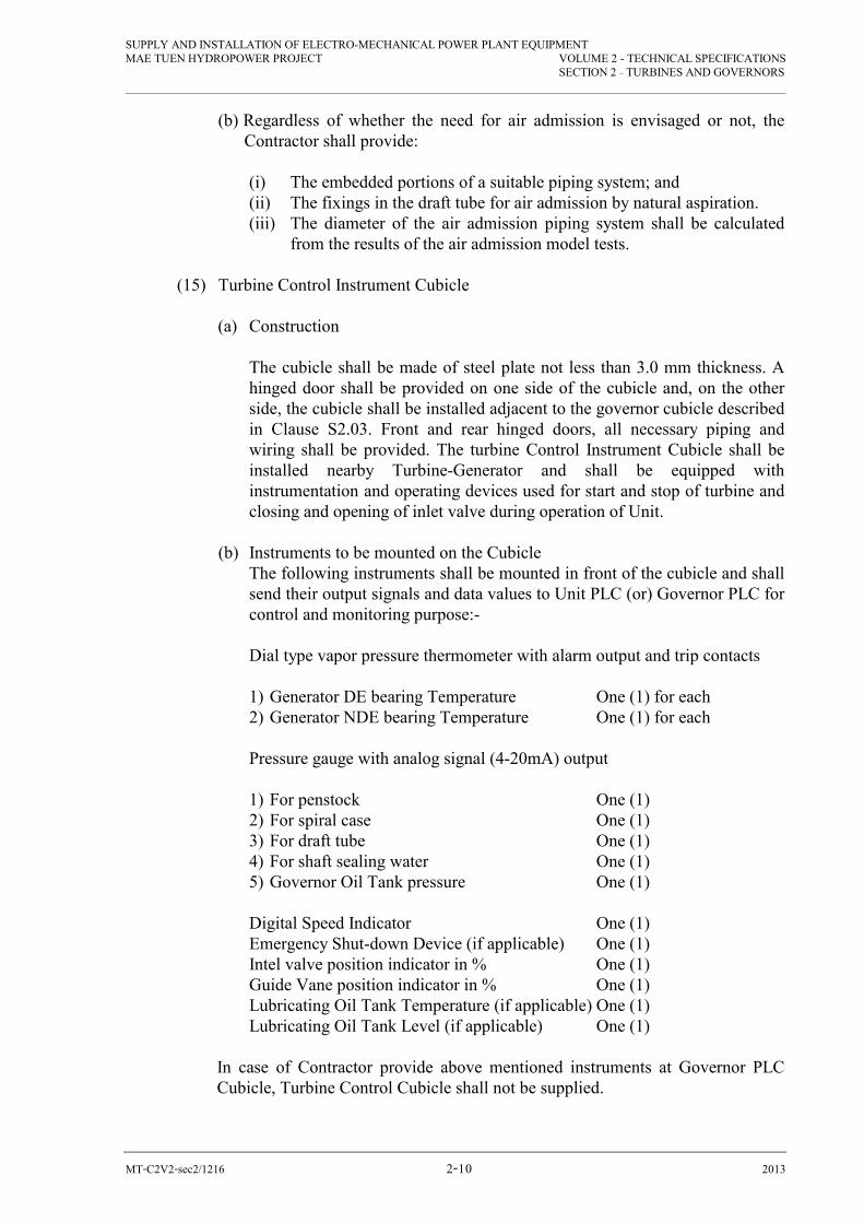
SUPPLY AND INSTALLATION OF ELECTRO-MECHANICAL POWER PLANT EQUIPMENT MAE TUEN HYDROPOWER PROJECT VOLUME 2 - TECHNICAL SPECIFICATIONS
SECTION 2 – TURBINES AND GOVERNORS
MT-C2V2-sec2/1216 �-�� 2013
(b) Regardless of whether the need for air admission is envisaged or not, the Contractor shall provide:
(i) The embedded portions of a suitable piping system; and (ii) The fixings in the draft tube for air admission by natural aspiration. (iii) The diameter of the air admission piping system shall be calculated
from the results of the air admission model tests. (15) Turbine Control Instrument Cubicle
(a) Construction The cubicle shall be made of steel plate not less than 3.0 mm thickness. A hinged door shall be provided on one side of the cubicle and, on the other side, the cubicle shall be installed adjacent to the governor cubicle described in Clause S2.03. Front and rear hinged doors, all necessary piping and wiring shall be provided. The turbine Control Instrument Cubicle shall be installed nearby Turbine-Generator and shall be equipped with instrumentation and operating devices used for start and stop of turbine and closing and opening of inlet valve during operation of Unit.
(b) Instruments to be mounted on the Cubicle
The following instruments shall be mounted in front of the cubicle and shall send their output signals and data values to Unit PLC (or) Governor PLC for control and monitoring purpose:-
Dial type vapor pressure thermometer with alarm output and trip contacts
1) Generator DE bearing Temperature One (1) for each 2) Generator NDE bearing Temperature One (1) for each
Pressure gauge with analog signal (4-20mA) output
1) For penstock One (1) 2) For spiral case One (1) 3) For draft tube One (1) 4) For shaft sealing water One (1) 5) Governor Oil Tank pressure One (1)
Digital Speed Indicator One (1) Emergency Shut-down Device (if applicable) One (1) Intel valve position indicator in % One (1) Guide Vane position indicator in % One (1) Lubricating Oil Tank Temperature (if applicable) One (1) Lubricating Oil Tank Level (if applicable) One (1) In case of Contractor provide above mentioned instruments at Governor PLC
Cubicle, Turbine Control Cubicle shall not be supplied.

SUPPLY AND INSTALLATION OF ELECTRO-MECHANICAL POWER PLANT EQUIPMENT MAE TUEN HYDROPOWER PROJECT VOLUME 2 - TECHNICAL SPECIFICATIONS
SECTION 2 – TURBINES AND GOVERNORS
MT-C2V2-sec2/1216 �-�� 2013
(16) Protection and Alarms (a) The Contractor shall provide protection functions for Generating Unit as per
the “Protection and Relaying Functions” specified under Control, Protection and Alarm Section as well as the applicable international standards.
(b) In addition to the devices listed, the Contractor shall provide such other
protection and alarm devices of all of them necessary for the safe operation of the turbine, governor, inlet valve and ancillaries and shall include for these in the Bid Price.
S2.03 GOVERNOR (1) Type
(a) The opening and closing of guide and servomotor shall be performed by governor system which shall comprise of with the digital type automatic PID controlled governing system with Control Cabinet and the oil pressure unit (or) hydraulic power unit. The system shall be independent, adjustable and control the guide vane operating mechanism unit to operate with an adequate margin of stability under all steady state and transient load conditions without hunting and shall operate stably and satisfactorily in parallel with each other and/or the interconnected with PEA Grid system.
(b) The governor controller shall be of the PID controlled digital type with an
established reputation of satisfactory and reliable service. Evidence of using PID Controller product catalog and information shall be provided with the Bid.
(c) The speed signal for the governor shall be derived from an approved source
which shall not be used for other functions. The source for the speed signal shall be wired directly to the governor without fuses or other electrical protection devices and it shall not be damaged by short-circuits. The source for the speed signal shall be sufficiently free from interference or distortion to ensure stable speed control of the unit and it shall have sufficient resolution to ensure accuracy of speed control. The Contractor shall also provide suitable frequency and load reference sources for the governor.
(d) The proposed location for the controller cabinet and oil pressure unit shall
be separated each other so that controller cabinet shall be located inside the control room (or) electrical room and oil pressure unit shall be located in turbine room. The Bidder shall submit the layout dimensional drawing locating controller cabinet and oil pressure unit separately with the Bid.
(e) The governor shall be provided with processing unit, I/O modules, power supply
modules, PT 100 temperature input modules, communication module and other components required for stable operation and control guide vane and its operating mechanism so that Operation and Control Sequence Diagrams (Start/ Stop) for Control System, Oil Pressure System Diagram, P&I Diagram with cooling water system shall also be submitted with the Bid.
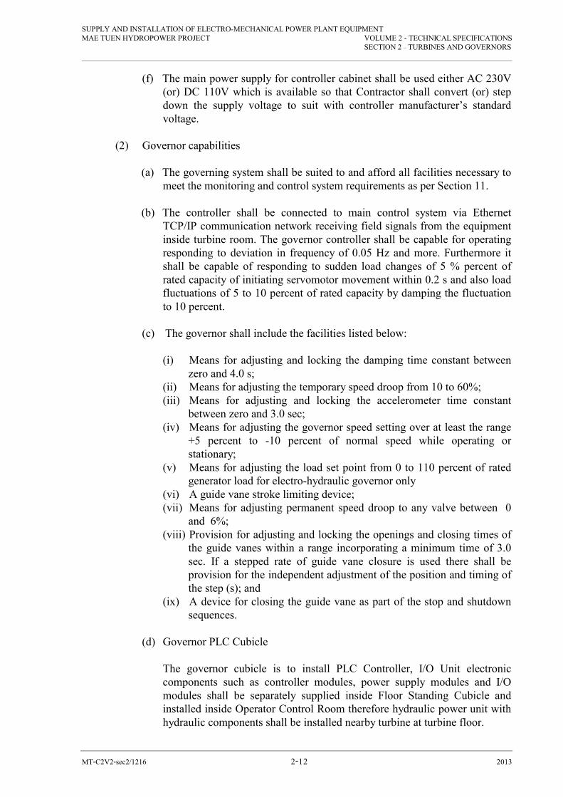
SUPPLY AND INSTALLATION OF ELECTRO-MECHANICAL POWER PLANT EQUIPMENT MAE TUEN HYDROPOWER PROJECT VOLUME 2 - TECHNICAL SPECIFICATIONS
SECTION 2 – TURBINES AND GOVERNORS
MT-C2V2-sec2/1216 �-�� 2013
(f) The main power supply for controller cabinet shall be used either AC 230V (or) DC 110V which is available so that Contractor shall convert (or) step down the supply voltage to suit with controller manufacturer’s standard voltage.
(2) Governor capabilities
(a) The governing system shall be suited to and afford all facilities necessary to meet the monitoring and control system requirements as per Section 11.
(b) The controller shall be connected to main control system via Ethernet TCP/IP communication network receiving field signals from the equipment inside turbine room. The governor controller shall be capable for operating responding to deviation in frequency of 0.05 Hz and more. Furthermore it shall be capable of responding to sudden load changes of 5 % percent of rated capacity of initiating servomotor movement within 0.2 s and also load fluctuations of 5 to 10 percent of rated capacity by damping the fluctuation to 10 percent.
(c) The governor shall include the facilities listed below:
(i) Means for adjusting and locking the damping time constant between
zero and 4.0 s; (ii) Means for adjusting the temporary speed droop from 10 to 60%; (iii) Means for adjusting and locking the accelerometer time constant
between zero and 3.0 sec; (iv) Means for adjusting the governor speed setting over at least the range
+5 percent to -10 percent of normal speed while operating or stationary;
(v) Means for adjusting the load set point from 0 to 110 percent of rated generator load for electro-hydraulic governor only
(vi) A guide vane stroke limiting device; (vii) Means for adjusting permanent speed droop to any valve between 0
and 6%; (viii) Provision for adjusting and locking the openings and closing times of
the guide vanes within a range incorporating a minimum time of 3.0 sec. If a stepped rate of guide vane closure is used there shall be provision for the independent adjustment of the position and timing of the step (s); and
(ix) A device for closing the guide vane as part of the stop and shutdown sequences.
(d) Governor PLC Cubicle
The governor cubicle is to install PLC Controller, I/O Unit electronic components such as controller modules, power supply modules and I/O modules shall be separately supplied inside Floor Standing Cubicle and installed inside Operator Control Room therefore hydraulic power unit with hydraulic components shall be installed nearby turbine at turbine floor.

SUPPLY AND INSTALLATION OF ELECTRO-MECHANICAL POWER PLANT EQUIPMENT MAE TUEN HYDROPOWER PROJECT VOLUME 2 - TECHNICAL SPECIFICATIONS
SECTION 2 – TURBINES AND GOVERNORS
MT-C2V2-sec2/1216 �-�� 2013
Evidence for proofing this separate design shall be submitted with the Bid. (3) Governor Oil Pumping System
(a) A complete governor pumping system shall be provided for each unit. Each system shall supply hydraulic oil for the opening and adjusting guide vane servomotor and the inlet valve servomotor. The governor system shall be suitable for the same grade of oil as the bearings.
(b) A separate oil and accumulator tank shall be designed and included in
Governor Oil Pumping System as per ASME Boiler and Pressure Vessel Code, Section III to resist the maximum allowable operating pressure including pressure switches, level control devices, pilot control valves, adjustable unloader valves, oil strainers at suction line of each pump, safety relief valves, check valves, temperature relay and hand operated valve for the complete operation for both governor oil pumping system and inlet valve opening hydraulic unit.
The hydraulic P&I diagram showing the above components shall be submitted in the Bid indicating oil cooling equipment.
(c) Duplicate AC motor-driven vertical pumps suitable for operation at 380Vac,
50Hz shall be provided for normal and standby duty respectively complying with IEC standards IP 54 Class F Insulation. The duties shall be interchangeable while in service setting via Governor PLC (or) Lead/ Lag selector switch. The rated capacity of each pump shall be not less than 1.5 times of total oil volume of servomotors sufficient for all requirements of the system. Each pump shall be complete with at least its own components as per item (b) so that either pump may be withdrawn for maintenance without affecting operation of the other. The strainer shall be fitted with a differential pressure indicator to give indication of the need for cleaning. The equipment layout arrangement drawing for oil pumping unit with proposed component list shall be submitted in the Bid to verify that Bidder is complying with the above requirements.
(d) The governor pumping system shall include a pressure receiver and oil sump
tank, each with oil level gauge (or) sight glass, one service manhole of dia 500mm with suitable oil resistant gaskets, means for maintenance purpose. Charging and make-up air shall be provided by the compressed air system pursuant to Clause S5.02 where applicable. The pressure receiver tank shall be 25 times of the total volume of guide vane servo motor cylinder and inlet valve servomotor having sufficient capacity to the turbine to be started and brought to full speed at any time within 8 hours after the loss of electric power supply to the standby governor oil pump and with the normal pump not commencing to rotate until the unit reaches normal speed and in addition to one complete closing stroke from low oil level or low pressure shutdown with the oil pump not operating.

SUPPLY AND INSTALLATION OF ELECTRO-MECHANICAL POWER PLANT EQUIPMENT MAE TUEN HYDROPOWER PROJECT VOLUME 2 - TECHNICAL SPECIFICATIONS
SECTION 2 – TURBINES AND GOVERNORS
MT-C2V2-sec2/1216 �-�� 2013
(e) The governor and inlet valve oil pipe work shall be arranged so that oil cannot drain from the servomotor cylinders, control valves or pipe work when the oil pressure supply is off. Air release points shall be provided on the servomotors and where necessary, on the pipework. The oil pressure supply shall be automatically isolated from the governing and inlet valve systems when the unit is stopped.
(f) The oil sump shall be fitted with a suction and return connection for oil
centrifuge equipment.
(g) Twin cartridge type strainers or an ‘auto-clean’ type strainer shall be fitted in the main oil pressure supply from the receiver. Each strainer shall be fitted with a differential pressure indicator to give indication of the need for cleaning. They shall be of sufficiently fine filtering capacity to prevent damage to any portion of the governing system by foreign matter Cartridge type strainers shall be capable of being individually removed for cleaning without shutting down the governor.
(h) A float valve or similar shall be fitted to the oil pressure supply connection
in the pressure receiver to prevent release of air in the event of abnormally low oil level in the receiver. The float valve shall be arranged to permit oil to be delivered into the receiver when the oil is at any level.
SECTION 3
INLET VALVES

SUPPLY AND INSTALLATION OF ELECTRO-MECHANICAL POWER PLANT EQUIPMENT MAE TUEN HYDROPOWER PROJECT VOLUME 2 TECHNICAL SPECIFICATIONS
SECTION 3 – INLET VALVES
MT-C2V2-sec3/1216 3-1 2013
SECTION 3 - INLET VALVES S3.01 TYPE AND CONSTRUCTION
(1) The turbine shall be provided with an inlet valve of the butterfly type designed for minimum head loss and disturbance and having a net cross-sectional area at the throat not less than of the spiral case inlet.
(2) The main elements of the valve shall be of cast, forged or fabricated steel. If fabricated construction is used, all welds stressed directly or indirectly by pipeline pressure shall, to the maximum extent practicable, be full penetration butt or tee-butt welds. All wearing parts shall be renewable and all such parts in contact with water shall be of corrosion resistant material or sleeved with corrosion resistant material.
(3) The sealing shall be by solid, rubber to metal, or metal to metal, contact between
the rotor seals and the body seats and shall not involve inflation or other similar forms of relative movement of elements in the seals or seats. If metal to metal contact between seal and seat is used the material shall be such that galling or pick-up cannot occur on contact. To this end the hardness of any parts between which contact or sliding occur shall differ by at least 50 Brinell hardness.
(4) The trunnion and servomotor connecting rod bushes shall be of greaseless, self-
lubricating type. Should weight closed valves be offered, provision shall be made to prevent dirt and foreign matter from entering the top of the servomotor.
(5) The seal leakage during both shop and site tests shall not leakage under a head of
60 m. of water column. (6) The seals, seats, trunnion bushes and trunnion glands shall be so arranged that
they can be removed or installed without dismantling the valve bodies or removing the valve from the pipe line.
(7) The Contractor shall provide steel pedestals to support the valve and transmit all
loads from the valve to the floor slab. (8) The Bidder shall submit the layout arrangement of Inlet Valve and bypass valve
together with dismantling pipes and drain pipe shall be submitted with the Bid. S3.02 OPERATION (1) The valve shall be capable of opening by governor pressure oil system and closing
against any flow up to and including that due to free discharge at the outlet of the valve with maximum water level in the upper reservoir.

SUPPLY AND INSTALLATION OF ELECTRO-MECHANICAL POWER PLANT EQUIPMENT MAE TUEN HYDROPOWER PROJECT VOLUME 2 TECHNICAL SPECIFICATIONS
SECTION 3 – INLET VALVES
MT-C2V2-sec3/1216 3-2 2013
(2) The valves shall be operated by oil pressure supplied by the governor pressure oil system. Operation in close direction shall be by counter weight.
(3) The hydraulic piston and its mounting, pressure piping and control valves shall be
adequate for the pressure operated by pressure unit with the most adverse conditions of unbalanced closure against free discharge.
(4) A manually operated mechanical lock for securing the inlet valve rotor in the
closed and open position shall be provided and shall be of adequate strength to resist the thrust of the servomotor in both the opening and closing directions. The locks shall embody provision for padlocking in the inserted and withdrawn positions.
(5) A system shall be provided for automatically checking, collecting and returning
oil to the governor oil sump tank any oil leakage of the servomotor. (6) The initiation of opening of the inlet valve shall be interlocked with the
establishment of a pressure in the spiral casing substantially equal to pipeline pressure.
(7) The inlet valve opening and closing times shall be independently adjustable but
the adjustments shall be of a form that cannot be readily or inadvertently altered. In the interests of minimizing the times necessary to start up and to shut down in an emergency, the opening and closing times shall be the minimum consistent with safe operation.
S3.03 CONTROL AND INDICATION (1) The control gear shall be such that the inlet valve may be opened and closed by
local manual mechanical control and remote control as part of the starting and stopping sequence. The valve controls shall be kept as simple as possible consistent with their function.
(2) Position indicators visible from the floor of the Machine Bay shall be provided for
the bypass valve, inlet valve rotor and mechanical lock. S3.04 BYPASS VALVE (1) The inlet valve shall be provided with a bypass valve, pipes and fittings,
preferable around 100 mm diameter. The purpose of by-pass valve is to fill water into the spiral casing and to balance the pressure between upstream and downstream side across the inlet valve, and the bypass valve shall be operated by DC motor (110Vdc) when the guide vanes and inlet valve are closed before starting the turbine-generator. A manually operated gate valve (normally open) shall also be provided together with bypass valve.

SUPPLY AND INSTALLATION OF ELECTRO-MECHANICAL POWER PLANT EQUIPMENT MAE TUEN HYDROPOWER PROJECT VOLUME 2 TECHNICAL SPECIFICATIONS
SECTION 3 – INLET VALVES
MT-C2V2-sec3/1216 3-3 2013
(2) The bypass valve shall be mounted directly on the connecting pipe (or) valve body and shall be complete with a pipe connection to the isolating valve which shall be mounted directly onto the penstock. The bypass valves shall be operated automatically operate electrically using 110V DC from PLC Control Command and manually operated by hand wheel of gate valve. Means shall be provided to ensure positive segregation of oil and water circuits.
(3) All wearing parts of the bypass valves including those susceptible to erosion or cavitation
shall be renewable and those in contact with water shall be of stainless steel or bronze. S3.05 DISMANTLING JOINT AND CLOSING PIECE
(1) A flanged stub pipe and a welded closing piece shall be provided to connect the inlet valve to the terminal point of the penstock. The closing piece shall be compatible for welding to the penstock and shall be designed in accordance with the criteria used for designing the spiral case. For inspection and maintenance of the inlet valve, the penstock will be closed with a blind flange and the operation of the other unit can resume after a short interruption.
(2) The closing piece shall include 150-200mm trimming allowance and shall incorporate connections for all equipment required to be connected to the pipeline under the Contract. The Contractor shall be responsible for trimming and fitting the closing piece and also for the making of the welded joints between the pipeline and the closing piece. These welds shall be subject to a 100 percent radiographic inspection.
(3) A flanged dismantling joint shall be provided between the spiral case and inlet valve. The dismantling joint shall be complete with nuts, bolts and jointing suitable for attaching to the inlet valve and spiral casing, the dismantling joint shall permit installation and removal of the inlet valve. The design shall be such that no forces are transmitted via the pipe to the turbine.
S3.06 PRESSURE CONDUIT AND TURBINE DRAIN SYSTEMS
(1) A 100 mm diameter manually operated gate valve and connecting pipes shall be provided with each turbine for draining water from penstock upstream to the draft tube. The conduit connection to penstock tappings shall be located upstream of the inlet valve in the stub pipe or closing piece. The embedded pipework provided by the civil works contractor shall be as shown on the Drawing.
(2) A 50 mm maximum diameter system of valve and piping shall be provided to drain water from the spiral case to the tailrace. The valve, piping and supports shall be suitable for operation under maximum unbalanced head and free discharge without appreciable vibration.
(3) The Bidder shall submit the layout arrangement of Turbine, Inlet Valve, bypass valve and pipe arrangement shall be submitted with the Bid.

SECTION 4
TESTS FOR TURBINE, GOVERNOR INLET VALVE AND AUXILIARIES, TURBINE MODEL TEST,
TERBINE FIELD EFFICIENCY TEST
SUPPLY AND INSTALLATION OF ELECTRO-MECHANICAL POWER PLANT EQUIPMENT MAE TUEN HYDROPOWER PROJECT VOLUME 2 - TECHNICAL SPECIFICATIONS
SECTION 4 – TESTS FOR TURBINE, GOVERNOR INLET VALVE AND
AUXILIARIES, TURBINE MODEL TEST, TURBINE FIELD EFFICIENCY TEST
MT-C2V2-sec4/1216 4-1 2013
SECTION 4 - TESTS FOR TURBINE, GOVERNOR INLET VALVE AND
AUXILIARIES, TURBINE MODEL TEST, TURBINE FIELD EFFICIENCY TEST
S4.01 TESTS FOR TURBINE, GOVERNOR, INLET VALVE AND AUXILIARIES
(1) Tests During Manufacture
(2) Tests During Manufacture
Turbines, governors, inlet valves and auxiliaries shall be subject to the following
tests at the Contractor’s premises and according to manufacturer’s standards with
IEC regulations.
Contractor shall provide manufacturer’s internal test reports such as balancing
reports, material test reports (or) certificates during the factory witness test so that
Witness Test Attendees shall verify comparing with shop drawings approved
during engineering stage.
Calibration Certificates of testing instruments shall be provided together with
Witness Test Reports.
The Contractor shall bare all travelling expenses (air tickets, accommodation,
meal, allowance, etc.) for two (2) DEDE Engineers (as Witness) for turbine,
mechanical parts to attend the test at factory and sign for approval of test results
before delivery to site.
(a) Material Tests
(i) Material tests on all important stressed components as defined in Clause
S1.17 (2).
(ii) Radiographic examination or ultrasonic examination of all major
castings and forgings. The areas proposed for such examination shall be
nominated by the Contractor when he submits drawings of the
components concerned in accordance with Clause 4.06 of Volume 1
and shall be subject to the approval of the Engineer. The decision as to
whether further examination is required shall be determined on the
incidence of defective materials disclosed by the initial examination.
The acceptability of the material shall be judged in accordance with
American Society for Testing Materials, cracks and hot tears being
‘unacceptable’, severity level 2 for all other forms of defect being

SUPPLY AND INSTALLATION OF ELECTRO-MECHANICAL POWER PLANT EQUIPMENT MAE TUEN HYDROPOWER PROJECT VOLUME 2 - TECHNICAL SPECIFICATIONS
SECTION 4 – TESTS FOR TURBINE, GOVERNOR INLET VALVE AND
AUXILIARIES, TURBINE MODEL TEST, TURBINE FIELD EFFICIENCY TEST
MT-C2V2-sec4/1216 4-2 2013
‘borderline’, as defined in those Standards. Any areas found by these
examinations to contain unacceptable defects shall be subject to re-
examination after repair.
(iii) Radiographic, ultrasonic examination and crack detection of welded
components in accordance with Clause S1.17
(iv) Crack detection of all castings and forgings.
(b) Hydrostatic Tests
(i) On all equipment subjected to water, oil or air pressure during normal
or abnormal working conditions, in accordance with the relevant
American Standards, subject to the test pressure being not less than 1.5
times the maximum working pressure but in no case less than 7
kg/cm2.
(ii) Leakage and deflection tests on all equipment stressed by pipeline
pressure.
(iii) Leakage tests with kerosene under gravity for all sump tanks.
(c) Tests on Unit Auxiliaries
(i) Motors for unit auxiliaries shall be subjected to type and routine tests.
(ii) All motor-driven auxiliary machines shall be run as complete units and
tested for starting current, running current, power factor, bearing
performance, gland tightness, noise and vibration.
(iii) One auxiliary machine of each type for connection to the unit auxiliary
system shall be tested to demonstrate satisfactory operation over the
range of voltage and frequency which many occur in service including
full-load rejection of the generator.
(d) Tests on Governors
Governor shall be test as per IEC publication 308 for the governor. And test
items to be submitted for approval by DEDE.
(3) Tests at Site
(a) Preliminary Tests
The preliminary tests for the turbines, governors, inlet valves and ancillaries
shall include the following:

SUPPLY AND INSTALLATION OF ELECTRO-MECHANICAL POWER PLANT EQUIPMENT MAE TUEN HYDROPOWER PROJECT VOLUME 2 - TECHNICAL SPECIFICATIONS
SECTION 4 – TESTS FOR TURBINE, GOVERNOR INLET VALVE AND
AUXILIARIES, TURBINE MODEL TEST, TURBINE FIELD EFFICIENCY TEST
MT-C2V2-sec4/1216 4-3 2013
(i) Radiographic (or) ultrasonic examination of all site welding parts as
defined in Clause S1.17.
(ii) Hydrostatic pressure tests on all pressure pipe systems. (The test
pressures shall be respectively the same as specified in Clause S4.01 (1)
(b) for the tests during manufacture).
(iii) Insulation and continuity tests on wiring including tests for correctness
of connection.
(iv) Checking for correct operation of each control, protection and
indication device.
(b) Tests on Completion
For the turbines, governors, inlet valves and ancillaries, the Tests on
Completion shall include the following:
Tests for correct operation, control, indication and protection of all ancillary
systems required to be in service for the operation of the turbine/generator
units including:
- Oil Pumping System (Governor)
- PLC Controlled Governor system
- Unit PLC Control
- Inlet valve and bypass valve operation
- Cooling water supply system
- Drainage System
- Brake System
- Final alignment check for rotation parts
- All instruments feedback signals from field to Control Systems
When water from penstock available for test, Contractor shall start drain for
penstock to assure that there is no external pieces inside penstock which may be
harmful and cause damage to Turbine parts and Inlet Valve so that Civil and
Electromechanical Contractor shall perform inspection together with DEDE
representatives and shall make agreement before Commissioning Wet Test.
No Load Heat Run Test, Load Heat Run Tests with Load rejection for different
load % for 25, 50, 75 and 100% respectively and 48 Hours PEA Grid Connected
Heat Run Test shall be performed for completion of Contract.

SUPPLY AND INSTALLATION OF ELECTRO-MECHANICAL POWER PLANT EQUIPMENT MAE TUEN HYDROPOWER PROJECT VOLUME 2 - TECHNICAL SPECIFICATIONS
SECTION 4 – TESTS FOR TURBINE, GOVERNOR INLET VALVE AND
AUXILIARIES, TURBINE MODEL TEST, TURBINE FIELD EFFICIENCY TEST
MT-C2V2-sec4/1216 4-4 2013
Contractor shall perform the followings during Commissioning Wet Test:-
(i) Speed, pressure and frequency regulation tests.
(ii) Check of pressure and output fluctuations.
(iii) Tests of correct functioning of controls, protection and indicating
equipment.
(iv) Test to prove that the delivered turbine and related equipment are
complying with the guaranteed efficiency and output as specified in the
Contract.
(v) The relevant sections of the ‘International Code for the Field
Acceptance Tests of Hydraulic Turbines’ IEC Publication 41 in so far
as this code is consistent with this Specification and the conditions at
Site, except that the tolerance shall be as stated in subparagraph (ii) of
this paragraph.
(vi) Tolerances allowing for inaccuracies of measurement, the following
tolerances shall be applied to performance figures ascertained from
Tests on Completion.
- Momentary speed rise - N + 2.0 percent absolute.
- Maximum pipeline pressure - N + 2.0 percent of the ascertained
figure.
- Power output - N +0.5 percent of the ascertained figure.
- Inaccuracy of efficiency for field test of turbines shall not exceed +
1.5 percent.
Tolerance according to IEC standards shall also be considered.
S4.02 TURBINE FIELD EFFICIENCY TEST
Field testing to verify the turbine efficiency and outputs shall be done by the
Contractor after completion of all installation works and dry test. The test procedures,
instrument used and date for the test shall be submitted to DEDE for approval.
Tests shall be carried out in accordance with the provisions set forth in “International Code
for the field Acceptance Test of Hydraulic Turbines” (IEC Publication 41) and the method,
diagram and the instruments used for the test shall be submitted with the Bid.
The Bidder shall indicate in his Bid at least two methods for measuring flow and shall
submit drawings with located indication including necessary provisions for the
penstock.

SUPPLY AND INSTALLATION OF ELECTRO-MECHANICAL POWER PLANT EQUIPMENT MAE TUEN HYDROPOWER PROJECT VOLUME 2 - TECHNICAL SPECIFICATIONS
SECTION 4 – TESTS FOR TURBINE, GOVERNOR INLET VALVE AND
AUXILIARIES, TURBINE MODEL TEST, TURBINE FIELD EFFICIENCY TEST
MT-C2V2-sec4/1216 4-5 2013
Failure to provide information may subject to the rejection of Bidder’s Proposal.
All instrument and cost required for performing the test shall be at the Contractor’s
expenses. Testing instrument shall be calibrated by an independent institute/organization
and it shall be submitted to DEDE for approval.
Should the result of the test show that the efficiency or the output is lower than the
corresponding guaranteed value, all the liquidated damage costs relevant to the test
shall be deducted from the Total Contract Price.
SECTION 5
MECHANICAL AUXILIARY EQUIPMENT

SUPPLY AND INSTALLATION OF ELECTRO-MECHANICAL POWER PLANT EQUIPMENT MAE TUEN HYDROPOWER PROJECT VOLUME 2 TECHNICAL SPECIFICATIONS
SECTION 5 – MECHANICAL AUXILIARY EQUIPMENT
MT-C2V2-sec5/1216 5-1 2013
SECTION 5 - MECHANICAL AUXILIARY EQUIPMENT S.5.01 UNIT COOLING WATER SYSTEM (1) General Description
(a) The Contractor shall provide one unit a separate cooling water system for supply to, and where necessary, the generating equipment of this plant during the unit is operating. The cooling water shall be taken from penstock which is upstream of the inlet valve. The location of tapping point shall be subject to the DEDE approval. The envisaged schematic arrangement of the unit cooling water system is shown on the Drawing. The details shown on the Drawing shall be taken as the minimum requirement. The items of Plant to be supplied by the unit cooling water system shall be for: (i) bearing lubricating oil system (ii) turbine shaft sealing (iii) Governor oil coolers (if required); and (iv) Any other unit auxiliary requires a supply of cooling water while that
unit is operating (v) general use
(b) The Contractor shall design and specify the flow requirements, size of piping
required and the operating head of the system.
(c) Bidder shall submit the cooling water system diagram showing valves, strainers, and instrument and pipe size together.
(2) Arrangement of Equipment (a) The system shall include duplicate automatic and manually operated self-
cleaning type filter (or) strainers drawing water from the penstock, and supplied for the Unit and other services as required.
(b) A stainless steel orifice for flow distribution adjustment, and a flow relay for
flow indication and flow failure alarm, shall be provided. The system shall be complete with automatic motor driven back-washing strainers (or) filters, all pipes, valves, pressure gauges, flow control valves, air releases and drains.
(3) Type and Construction of Equipment
(a) A.C. Motor Driven A.C. motor driven isolating valve shall be controlled during turbine start and stop sequences.
SUPPLY AND INSTALLATION OF ELECTRO-MECHANICAL POWER PLANT EQUIPMENT MAE TUEN HYDROPOWER PROJECT VOLUME 2 TECHNICAL SPECIFICATIONS
SECTION 5 – MECHANICAL AUXILIARY EQUIPMENT
MT-C2V2-sec5/1216 5-2 2013
(b) Strainers (i) The strainers shall be of the automatic and manually operated self-
cleaning type, with mesh openings of not more than 3 mm and in any case small enough to exclude any foreign matter large enough to cause damage (or) blocking in any part of the system.
(ii) Any discharge from the strainers resulting from a backwash of flushing cycle shall be piped to drain. The mesh shall be of corrosion resistant material and the strainer bodies and covers shall be galvanized internally and externally.
(iii) The strainers shall each have an automatic air release valve with discharge piped to drain. The head across the strainer when 30 percent blocked shall not exceed 1.5 meter of water.
(c) Portable Chemical Feeder (not applicable)
(i) Cooling water conditions may produce bacterial growth in the water
passages of the various heat exchange systems. (ii) A portable chemical feeder shall be provided to enable periodic
injection of suitable concentration of hydro-chloric acid or sodium hypochlorite into each unit cooling water system in order to control the bacterial growth. It is expected that approximately ten parts per million residual chlorine will be required in the cooling water systems, however the chemical feeder shall provide for a range of feed rates which shall be fully adjustable.
(iii) The chemical feeder shall consist of a tank, pump, filter, check valve, pipes, swivel type injection connections for pipe coupling and other necessary instruments and shall be provided with a control panel, electrical cord and plug. The pump shall be of the positive displacement type driven by an electric motor. Two (2) flexible tubes shall be provided to connect the chemical feeder to the injection point in the cooling water system. The chemical feed unit and tank shall be mounted on a four wheel hand truck with pull bar and lifting eyes at each corner. The equipment shall be neatly arranged and provision shall be made for storing flexible tubes and electrical cord.
(iv) The chemical injection points for each unit cooling water system shall be located upstream of the Unit cooling water system and accessible from the machine hall floor level.
(d) All piping for unit cooling water system shall be of seamless steel pipes with
bolted flange connection.

SUPPLY AND INSTALLATION OF ELECTRO-MECHANICAL POWER PLANT EQUIPMENT MAE TUEN HYDROPOWER PROJECT VOLUME 2 TECHNICAL SPECIFICATIONS
SECTION 5 – MECHANICAL AUXILIARY EQUIPMENT
MT-C2V2-sec5/1216 5-3 2013
S5.02 COMPRESSED AIR SYSTEM (if necessary) (1) General Description (a) The common compressed air system will be used to supply operation air to
the following equipment:
(i) Turbine governor pumping set oil/air pressure receivers (ii) Maintenance service points at erection bay and machine bays and
generator brakes.
(b) The Contractor shall determine the capacity of compressor, primary chamber and air receiver, the normal operating pressure and pipe size so that the charging of a governor pressure receiver from atmospheric to working pressure can be achieved in 0.5 hours.
(2) Arrangement of Equipment
The system shall comprise two motorized air cooled compressors for normal and standby duty respectively. The duties shall be interchangeable while in service. Each compressor shall be included a silencer, intake, filter, governor type drainage valve, primary chamber, after-cooler, non-return valve and isolating valve delivering into the air receiver. The compressor shall be controlled by air pressure in the high pressure air receiver, connection of high and low pressure air receiver shall be made by pressure reducing valve and solenoid valve which shall be controlled by the air pressure of low pressure air receiver.
The compressors shall be arranged to operate by automatic and manual control. The system shall be complete with all pipes, fittings and connections, manual valves, temperature and pressure gauges.
(3) Compressors
(a) The compressors shall be continuously rated and of a reciprocating, air cooled pattern.
(b) All working parts shall be replaceable.
(c) The compressors shall be provided with after-cooler and, where necessary inter-coolers. They shall be air cooled and the tube nests shall be replaceable. The tubes shall be of corrosion resistant material. Each cooler shall be complete with moisture separator and automatic trap fitted with sight glass assembly.
(d) Main bearings, and for reciprocating compressors, connecting rod and crosshead bearings shall be oil pressure lubricated by a pump mechanically driven from the compressor. Where separate cylinder or rotor lubrication is provided, the oil pump shall be mechanically driven from the compressor.

SUPPLY AND INSTALLATION OF ELECTRO-MECHANICAL POWER PLANT EQUIPMENT MAE TUEN HYDROPOWER PROJECT VOLUME 2 TECHNICAL SPECIFICATIONS
SECTION 5 – MECHANICAL AUXILIARY EQUIPMENT
MT-C2V2-sec5/1216 5-4 2013
(e) The pressure oil system shall include a suction strainer, sump level indicator and full flow strainer of either the replaceable cartridge or cleanable edge filtration type.
(f) Crankcases shall be enclosed when the compressor is operating. Cooling
jackets, air cowlings and crankcases shall have adequate access for cleaning and inspection.
(g) Intake shall be provided with suction silences and an air cleaner of either the
oil bath or replaceable cartridge type. (h) Compressors shall be fitted with protective devices to stop the compressor in
the event of low oil pressure or high air delivery temperature. (i) Compressors shall be fitted with starting unloaders such that the unit reaches
full speed before air delivery commences. (j) Motors and compressors shall be rigidly mounted on a common base plate to
maintain correct alignment. All moving parts shall be enclosed. The base plate shall minimize the transmission of vibration to the foundation.
(4) Air Receivers and Air/Oil Receivers
(a) Compressed air receivers and air/oil receivers shall be designed and
constructed in accordance with ASME Standard. (b) The receivers shall be fitted with safety valves, pressure gauges and
automatic and manual condensate drains. (c) The Contractor shall provide detailed shop drawings and calculations for the
design of the receivers sufficient for the DEDE Engineer to check compliance with ASME requirements.
S5.03 VENTILATION AND AIR-CONDITIONING SYSTEMS (1) General (a) The Contractor shall design, supply and install the ventilation and air-
conditioning systems in the power station. The system shall comprise:
(i) Three air-conditioning split type ceiling mounting, each for the Control Room, 24,000 BTU-HR Sealed Energy Save No.5.
(ii) Three air conditioning, spit type for office 24,000 BTU-HR Sealed Energy Saving No.5.
(iii) Individual ventilation systems for the following rooms: - Toilets - window mounted exhaust fan

SUPPLY AND INSTALLATION OF ELECTRO-MECHANICAL POWER PLANT EQUIPMENT MAE TUEN HYDROPOWER PROJECT VOLUME 2 TECHNICAL SPECIFICATIONS
SECTION 5 – MECHANICAL AUXILIARY EQUIPMENT
MT-C2V2-sec5/1216 5-5 2013
- Diesel Room - exhaust fan - Battery Room - exhaust fans - Control Room - supply/exhaust fans - Office Room - supply/exhaust fans - Switchgear Room - exhaust fan
(b) Each system shall include control and indicating instruments and all electrical wiring.
S5.04 POWERHOUSE WATER DRAINAGE SYSTEM
(1) General Description
(a) The station drainage pumping system shall consist of two sump pumps and motors each of 4 L/s capacity when operating in the drainage pit. Schematic arrangement of pumps and pipework is shown on Drawing.
(b) The drainage pumps will be used to remove normal seepage, drainage water, and spiral casing drainage water which will be directed by gravity drains into the drainage pit. The pumps shall be supplied with quick release couplings such that a pump can be removed and used as a portable pump for drainage of a draft tube. The pumps will also be used to drain the inlet valve pits under emergency conditions such as a burst connection from a pressure conduit. The Contractor shall determine the size of piping required and the head against which the pump must operate to enable complete drainage of a turbine draft tube.
(c) The drainage water may vary from the normal site ‘clean’ condition to a
condition where it contains silt, small suspended material and contaminants such as lubricating oil, kerosene and grease in concentrations up to approximate 150 ppm.
(2) Arrangement of Equipment: The system shall comprise two drainage pumps each
with its own discharge piping, pressure gauge, check valve, and gate valve. The pumps shall operate under both manual and float switch control. The float switches shall be arranged to operate in accordance with levels. The duties of the two normal drainage pumps shall be interchangeable by manual controls.
(3) Type and Construction
(a) The pumps shall be submersible, bottom suction, vertical shaft units with quick release coupling suitable for operating while submerged for indefinite periods and after being stationary for long periods. The design and construction of the motors shall prevent the entry of external water, foreign material or contaminants into the motors or their cooling systems under all conditions.
SUPPLY AND INSTALLATION OF ELECTRO-MECHANICAL POWER PLANT EQUIPMENT MAE TUEN HYDROPOWER PROJECT VOLUME 2 TECHNICAL SPECIFICATIONS
SECTION 5 – MECHANICAL AUXILIARY EQUIPMENT
MT-C2V2-sec5/1216 5-6 2013
(b) The pumps shall be held with guide rail in the pit and can be remove by sliding up along the guide rail.
(c) The pumps shall be driven by 230 V, single-phase motors. Provision shall
be made for replenishing the cooling lubricant if required.
(d) The float switches shall be suitable for submerged operation. They shall be mounted in a vertical steel pipe which shall be located in the drainage pit. Off takes from the sump to the float switch pipe shall be equipped with mesh strainers. The float switch pipe complete with float switches shall be arranged so that it may be easily removed from the drainage pit.
(4) Piping and Fittings: The Contractor shall supply duplicate galvanized piping together with all steelwork and fittings for locating the pumps and float switch pipe within the drainage pit.
S5.05 PORTABLE FIRE EXTINGUISHERS
(1) The Contractor shall supply portable fire extinguishers complying with accepted standards. Each extinguisher shall be mounted on suitable bracket on the wall at location to be advised by the DEDE Engineer.
(2) Extinguishers shall be red with a glossy baked enamel finish, chrome-plated trim
and safety pin. (3) The following table lists the quantities of portable fire extinguishers required. For
those type of extinguishers where it is possible to supply either a model which can be refilled on site or a model which must be returned to a factory for refilling, the model which can be refilled on site shall be supplied, fully charged on complete with one (1) spare refill for each extinguisher.
TABLE S5.05-1
FIRE EXTINGUISHERS
Location Minimum Capacity
CO2 Dry Chemical
Erection bay 6 kg 1 1 Control room 6 kg 2 1 Office area 6 kg 1 - Diesel room 6 kg 1 1 Machine bay 6 kg 2 1 Battery room 6 kg 1 - Store room 6 kg 1 1 Switchgear room 6 kg 1 1
SUPPLY AND INSTALLATION OF ELECTRO-MECHANICAL POWER PLANT EQUIPMENT MAE TUEN HYDROPOWER PROJECT VOLUME 2 TECHNICAL SPECIFICATIONS
SECTION 5 – MECHANICAL AUXILIARY EQUIPMENT
MT-C2V2-sec5/1216 5-7 2013
S5.06 OVERHEAD TRAVELING CRANE
(1) Type and Rating
(a) The Contractor shall provide an electrically driven, pendant controlled, overhead traveling, and top running bridge type crane for the Powerhouse, together with a set of crane rails, longitudinal travel collector wires and associated equipment, four end buffers for the longitudinal travel and permanently fixed ladder and platform for routine maintenance.
(b) The capacity of the crane shall not be less than 3 tons however the Contactor shall be supplied depending on the heaviest weight of equipment to be lifted during erection and maintenance of the turbines, inlet valves and generators.
(c) The crane shall be design, constructed, erected and commissioned in accordance with CMAA or equivalent standards.
(d) The height of lift of the crane and the limits of traverse and travel of the
crane hook shall be determined by the Contractor and shall be sufficient for all erection and maintenance operations on the Plant in the Powerhouse Machine Bay.
(e) The limits of lifting traverse and travel of the crane hook shall give the
maximum possible coverage within the Powerhouse. (f) The crane will constitute a prominent feature of the Powerhouse and shall be
designed to present an appearance aesthetically in keeping with this role and with the interior architecture of the Powerhouse.
(2) Operating Requirements (a) The crane shall have electrically driven hoisting (two speeds), traversing and
traveling motions controlled by a low voltage push-button pendant. The pendant shall be movable horizontally along the crane bridge and located vertically for operation from the machine bay floor.
(b) The operating speeds of the crane shall be within the following ranges:
Hoist Normal 0.050 m/s Creep 0.005 m/s Traverse Normal 0.33 m/s Creep 0.08 m/s Travel Normal 0.60 m/s Creep 0.16 m/s Minimum Height of Lift 10 m

SUPPLY AND INSTALLATION OF ELECTRO-MECHANICAL POWER PLANT EQUIPMENT MAE TUEN HYDROPOWER PROJECT VOLUME 2 TECHNICAL SPECIFICATIONS
SECTION 5 – MECHANICAL AUXILIARY EQUIPMENT
MT-C2V2-sec5/1216 5-8 2013
(3) Crane Runway (a) General
The Contractor shall supply and install all sole plates and anchor bolts for the crane rails, longitudinal travel buffers and limit switch strikers.
(b) Span
The span of the crane runway rails measured centre to centre shall be 14.0 m + 2 mm.
(c) Rails
The crane runway shall consist of jointed flat bottom rail and shall be installed to within +2 mm of level for its full length. Each section of each crane runway rail shall be interconnected and the rails shall be connected by grounding conductors to the Powerhouse grounding system.
(d) Longitudinal Travel Buffers
Four longitudinal travel buffers complete with soleplates and holding down bolts shall be supplied and installed by the Contractor, one set for each end of the runway.
(e) Longitudinal Travel Limit Switch Strikers
Two longitudinal travel limit switch strikers shall be supplied and installed by the Contractor. These shall be positioned to provide a possible overrun of 150 mm when the limit switched trip.
(4) Construction Requirements
(a) Crane Structure
(i) The crane shall be of fabricated steel construction. The bridge shall consist of one main girders connected together at each end by means of a substantial cross beam. The vertical deflection caused by the rated load plus the trolley shall not exceed length/ 1,000 of span. Floor plate walkways and steel handrails shall be provided, and shall be suitable for routine maintenance of crane parts. The securing of the main girders to end carriages shall be by high tensile bolts and nuts to assure correct alignment and easy erection.
(ii) The complete bridge structure shall be mounted on end carriages. Each end carriage shall contain wheels which rotate on antifriction bearings mounted on simply supported axles. The design of each end carriage shall be such that easy inspection and wheel removal is possible. In the
SUPPLY AND INSTALLATION OF ELECTRO-MECHANICAL POWER PLANT EQUIPMENT MAE TUEN HYDROPOWER PROJECT VOLUME 2 TECHNICAL SPECIFICATIONS
SECTION 5 – MECHANICAL AUXILIARY EQUIPMENT
MT-C2V2-sec5/1216 5-9 2013
event of a wheel shaft breaking it shall not be possible for the crane and carriage to drop more than 33 mm.
(iii) Four travel buffers shall be attached to the outer bogies; one for each can stop at the end of each crane runway.
(b) Longitudinal Travel Mechanism
The longitudinal travel drive units shall be identical motorized geared units ensuring smooth operation of the longitudinal travel. The high precision gears of these units are run in the oil bath. Each drive unit shall be equipped with the electro mechanical brake operators according to the sliding rotor principle which shall be capable of being replaced without removing other components. The brakes shall be capable of being applied gradually to minimize swaying of the load and shall operate automatically when the supply to the motor is interrupted. The travel motor is designed as a drive unit for acceleration and safe deceleration of high-inertia load.
(c) Low Headroom Monorail Hoist
(i) The hoist motor shall drive the hoist drum by central drive. The hoist
drive shall be fitted with an automatic, spring applied, energized to release, brake. The hoisting drum shall be steel or cast iron and shall have accurately machined grooving to accommodate the hoisting rope in single layers. The hoisting rope shall be performed, non-rotating construction.
(ii) The hook of the crane fall block shall be of swiveling type, supported on a ball or roller thrust bearing. The fall block shall be provided with shrouded sheaves. The fall block sheaves, compensating sheaves, and reeling return sheaves shall have machined grooves and shall be mounted on ball or roller bearings.
(iii) The motor torque is transmitted to the reduction gear through a flexible coupling to cushioning high starting torque peaks.
The minimum breaking strength of the rope shall be not less than five (5) times the hoist’s rated load.
(d) General
(i) All gearing other than final drives, shall be enclosed in gear cases.
The gearboxes shall be fitted throughout with ball or roller bearings. Gearing shall be designed in accordance with the AGMA Class II with a minimum service factor of 1.25.
(ii) All shafting to which gears, pinions and other similar parts are fitted, shall preferable be provided with a raised portion and/or shoulder where such parts are carried. Any change of section of shaft shall be effected with fillets of ample radius.
(iii) All bearings and other wearing surfaces shall be provided with means for lubrication, preferably by automatic circulation. Points for lubrication by

SUPPLY AND INSTALLATION OF ELECTRO-MECHANICAL POWER PLANT EQUIPMENT MAE TUEN HYDROPOWER PROJECT VOLUME 2 TECHNICAL SPECIFICATIONS
SECTION 5 – MECHANICAL AUXILIARY EQUIPMENT
MT-C2V2-sec5/1216 5-10 2013
grease gun shall be suitable for the same make and grade of grease and shall each be provided with a separate grease nipple of the all steel, one piece button-head type. All grease nipples shall be readily accessible and grouped wherever possible. Removable; sheet steel guards shall be provided for open gearing.
(iv) All gear boxes, motors, bearings, etc. shall be positively located after alignment, other than by their holding down bolts.
(v) All platforms shall have 75 mm high kick strips at their edges.
(e) Electrical Equipment
(i) All electrical equipment shall be suitable for operation from the 400 V, 50 Hz three-phase four-wire supply from the AC Station Service Distribution Board. The Contractor shall provide, on the crane, adequately rated single phase transformers, suitable for continuous operation for the supply of power to the control circuits, lighting and power outlet circuits and ‘POWER ON’ indicator light circuits.
(ii) The electrical power supply to the crane shall be by means of three shrouded hard drawn copper collector wires supported by brackets, attached to the building above crane runway level. Red indicator lights shall be installed between phases at the end of the collector wires to show that collector wires are energized. The Contractor shall supply and install the collector wires, three collectors or renewable carbon head type, and all necessary and strainers, brackets, insulators, collector wire guards, and other fittings, together with a ‘lock-off’ type isolating switch and all wiring and conduit from this switch to the point of connection to the three longitudinal collection wires. The isolating switch shall be labeled ‘CRANE ON/OFF’.
(iii) All motors shall be half-hour rated for the required duty cycle. (iv) A control and protection panel enclosed in a cabinet, of dustproof,
sheet metal construction, incorporating a hinged door and hinged panel, shall be mounted on the crane bridge. The equipment shall include an externally operated triple-pole main isolating switch, triple-pole main contactor, triple-pole ganged magnetic overload relays for each motor and all necessary fuses, control switches and wiring for the motors, control circuits, and one single-phase switched socket outlet. A ‘POWER ON’ indicating light shall be fitted to the cabinet.
(v) A fall block operated, whole current over hoisting limit switch shall be provided for the hoist. In addition, a shunt type limit switch shall be fitted to the hoist to limit the travel in the ‘raise’ and ‘lower’ directions. Shunt type limit switches shall be provided also for the cross-traverse and longitudinal travel motions. All limit switches shall be self-resetting and shall be electrically connected in a manner permitting ‘backing out’ after tripping.
(vi) The traverse power take off shall consist of an approved trailing cable system. An isolating switch shall be provided at the point of entry to

SUPPLY AND INSTALLATION OF ELECTRO-MECHANICAL POWER PLANT EQUIPMENT MAE TUEN HYDROPOWER PROJECT VOLUME 2 TECHNICAL SPECIFICATIONS
SECTION 5 – MECHANICAL AUXILIARY EQUIPMENT
MT-C2V2-sec5/1216 5-11 2013
the crab platform. This switch shall isolate the cross-traverse motion and shall be labeled “CROSS TRAVERSE-ON/OFF”.
(vii) All crane wiring shall be installed in screwed conduit. (viii) The control pendant shall preferable operate at 24 V but not more than
50 V. The push buttons shall return to the off position when pressure is released. The pendant shall include a power on/off switch. The buttons for each motion shall be grouped together and shall be logically identified. The electrical conductors to the pendant shall not be used to support its weight. The pendant shall incorporate a ‘power on’ indicating light.
S5.07 DIESEL-DRIVEN STANDBY ELECTRIC POWER SYSTEM
(1) Scope
The work to be done under this section includes the design, manufacture, supply, shop testing, delivery, and the installation, testing, initial operation and complete with auxiliaries, capable of fully automatic black start and loading.
The work to be finished by the Contractor shall include the following.
(a) Diesel Engine - Diesel engine - Governor - Fuel oil system - Lubricating oil system - Cooling system - Air intake system - Exhaust system - Engine starting system, including battery and automatic charger - Engine protective devices and instruments and control panel (b) Generator - Generator - Excitation system - Generator protective devices - Generator instruments, and control panel (c) Steel Base for Unit Mounting - Steel base - Vibration dampeners - Oil drip pan covering full length of base
(2) Application
In the event of a failure of the incoming power, the diesel engine driven generator set will automatically start and be used to provide standby electric power to assist

SUPPLY AND INSTALLATION OF ELECTRO-MECHANICAL POWER PLANT EQUIPMENT MAE TUEN HYDROPOWER PROJECT VOLUME 2 TECHNICAL SPECIFICATIONS
SECTION 5 – MECHANICAL AUXILIARY EQUIPMENT
MT-C2V2-sec5/1216 5-12 2013
in starting hydro-generating unit. The ambient air has H2S present and equipment shall be designed accordingly.
(3) Requirements for Design
The rating of the generator, and thus the diesel, shall be suitable for the following duties.
(a) The base continuous load that the diesel shall carry at all times will be the essential and emergency lighting, communication equipment, 2 battery chargers, cooling water system supply, 1 control building air conditioner and condenser unit, the town site water pump, guardhouse power supply and 1 station air compressor.
(b) The diesel generator must be capable of starting the largest motor on the essential services distribution panel board with a base continuous load as specified in (a).
Preliminary sizing of the diesel generator indicates that 60 kVA at 0.8 PF is required. Final rating selection shall be made by the Contractor based on detailed load calculations.
The unit shall be capable of starting and loading automatically, as required, and of supplying an isolated load. Final design and rating shall be approved by DEDE.
(4) Diesel Engine and Auxiliaries
(a) Diesel Engine The diesel engine shall be capable of operating on normal diesel fuel and shall not require premium diesel fuel for satisfactory performance. The engine shall be rated to produce required output at 45oC ambient temperature and 99 percent relative humidity.
The diesel engine may be either normally aspirated or supercharged.
The engine and generator shall be supplied complete with a common bedplate suitable for mounting on a concrete foundation. Adjustable steel spring type vibration isolators with sound pads shall provided for mounting between the unit base and concrete foundation. A suitable oil drip pan shall be provided under the full length of the diesel and generator to catch oil leakage.
(b) Governor The engine shall be equipped with a suitable governor for 50 Hz operation. The engine shall have a separate overspeed trip device to stop the engine in the event of the engine exceeding its safe speed.

SUPPLY AND INSTALLATION OF ELECTRO-MECHANICAL POWER PLANT EQUIPMENT MAE TUEN HYDROPOWER PROJECT VOLUME 2 TECHNICAL SPECIFICATIONS
SECTION 5 – MECHANICAL AUXILIARY EQUIPMENT
MT-C2V2-sec5/1216 5-13 2013
(c) Fuel Oil System This system shall include for one 120 L, standard indoor fuel tank complete with fill-connecting piping, vent pipe, level indicator, low-level alarm, cradles and supporting structure, mounted for gravity feed to the engine pump. The system shall be complete with all interconnecting fuel oil piping and flexible connections. One hand-operated fuel pump shall be provided for pumping fuel from barrels to fuel tank.
(d) Cooling System
The cooling system shall be air cooled or oil cooled with shaft driven air fan.
(e) Air Intake System
This system shall include an engine air cleaner, complete with support structure, intake piping, flexible connections and piping supports as required. The filter elements of the air cleaner shall be of a washable type. A differential pressure indicator shall be provided across the filter to indicate when the filter elements require cleaning.
(f) Exhaust System
This system shall include a muffler, complete with support structure, exhaust piping, flexible connections, pipe supports, and insulation for exhausting from building. The muffler is to be located inside the building. The exhaust system inside the building shall be suitably insulated over its entire length Noise is a critical factor and the Contractor shall include the best muffler system available.
(g) Starting System
This system shall include a heavy-duty starting motor, regulator, batteries of ample capacity, battery rack, jumpers, cables and 2-rate automatic battery charger.
(h) Protective Devices The engine shall be provided with all necessary protective devices, safety features and controls which shall include, but not be limited to:
- Low oil pressure cutout - Automatic over speed shutdown - Over crank shutdown

SUPPLY AND INSTALLATION OF ELECTRO-MECHANICAL POWER PLANT EQUIPMENT MAE TUEN HYDROPOWER PROJECT VOLUME 2 TECHNICAL SPECIFICATIONS
SECTION 5 – MECHANICAL AUXILIARY EQUIPMENT
MT-C2V2-sec5/1216 5-14 2013
(i) Control Panel The engine control panel shall be mounted on the unit and shall include, but not be limited to, the following instruments and controls. - Complete engine automatic starting controls, including a test switch - Safety devices - lubricating oil pressure gauge - lubricating oil temperature gauge - Tachometer/hour-meter - Start-stop automatic switch - Automatic-manual control selector switch - Cranking limiter - Individual signal lights, manual resets, and common alarm terminal. Remote alarm Annunciator shall be provided in the control room.
(j) Special Tools
The Contractor shall supply one set of any special tools necessary for the complete servicing and maintenance of the engine and all auxiliaries. The Contractor shall provide one barrel hand pump with all hoses, connectors and fittings to fill the storage tank from standard fuel oil barrels.
(5) Generator and Exciter
(a) Generator and Exciter
The generator shall have a continuous rating of 60 kVA, 0.8 PF, 400/230V, 3-phase, 4-wire, 50 Hz, and shall be capable of operating at 110 percent load at rated power factor and frequency for a minimum of 1 hour.
The unit shall be suitable for operation in a tropical climate, as stated in previous sections of the Specifications.
The generator shall be equipped with a direct coupled, brushless or static exciter, designed and rated to match the generator characteristics.
(b) Construction
The generator and exciter shall be air-cooled, self-fan, ventilated type, in a drip-proof enclosure.
Winding insulation shall be Class F. The generator shall be provided with a full amortisseur winding.

SUPPLY AND INSTALLATION OF ELECTRO-MECHANICAL POWER PLANT EQUIPMENT MAE TUEN HYDROPOWER PROJECT VOLUME 2 TECHNICAL SPECIFICATIONS
SECTION 5 – MECHANICAL AUXILIARY EQUIPMENT
MT-C2V2-sec5/1216 5-15 2013
(c) Voltage Regulator A solid-state voltage regulator shall be supplied, capable of maintaining the output voltage within 1 percent of the rated voltage over the full operating range of the generator. Provision shall be made for manual adjustment of the regulated output voltage from 10 percent below to 10 percent above the nominal rated voltage.
(6) Generator Control Panel
A totally enclosed sheet steel control panel with front hinged access door shall be supplied to house the following generator control equipment:
- AC voltmeter and ammeter with selector switch - Automatic voltage regulator - Frequency meter (48 to 52 Hz) - Protection relays - Battery, Charger with charging ammeter and voltmeter - Automatic control and timing relays as required performing the functions of
start/ stop diesel generator, closing generator breaker (located in AC station switchgear) when generator is up to normal frequency and voltage
The starting and stopping functions shall be controlled through separate timing relays to permit adjustable delay in starting and stopping over a range of 0.1 seconds to 10 minutes by both Locally or HMI PLC.
(7) Equipment Bases
The Contractor shall supply and install all equipment concrete bases. Final setting on bases shall be cement grout. The Contractor shall provide connecting bolts, gaskets, leveling shims and washers, and shall supply the anti-vibration mounts for the diesel-generator unit and auxiliaries. Each piece of equipment shall be installed strictly in accordance with the manufacturer’s instructions. The complete initial lubrication of all equipment, including all gear cases, sump, and other oils shall be provided by the Contractor. All equipment shall be factory painted in keeping with the requirement of Clause S1.11.

SECTION 6
TESTS FOR MECHANICAL AUXILIARY EQUIPMENT
SUPPLY AND INSTALLATION OF ELECTRO-MECHANICAL POWER PLANT EQUIPMENT MAE TUEN HYDROPOWER PROJECT VOLUME 2 TECHNICAL SPECIFICATIONS
SECTION 6 – TEST FOR MECHANICAL AUXILIARY EQUIPMENT
MT-C2V2-sec6/1216 6-1 2013
SECTION 6 - TESTS FOR MECHANICAL AUXILIARY EQUIPMENT
S6.01 TEST DURING MANUFACTURE (Except powerhouse crane) The mechanical auxiliary equipment shall be subject to the following tests at the
Contractor’s premises.
(1) Material Tests
Material tests shall conform to the requirements of Clause S4.01 (1) (a).
(2) Hydrostatic Tests
Hydrostatic tests shall conform to the requirements of Clause S4.01 (1) (b). (3) Performance Tests (a) Operating tests on all electric motors under conditions simulating the actual
service for output, efficiency, power factor, temperature rise including oscillograms of starting and running current voltage.
(b) Hydraulic, pneumatic and electric tests on all pumps, compressors, air-
conditioning units and fans under conditions simulating the actual service to demonstrate that the performance complies with the Contract and to establish complete operating characteristics. Particular attention shall be paid to limiting noise and vibration levels.
(c) Performance tests on the air-conditioning units.
S6.02 TESTS AT SITE (Except powerhouse crane) (1) Preliminary Test
The preliminary tests for the mechanical auxiliary equipment shall include the followings:
(a) Hydrostatic pressure tests on all piping systems. The test pressures shall be
respectively the same as specified in Clause S4.01 (1) (b).
(b) Insulation and continuity tests on wiring including tests for correctness of connection.
(c) Checking pipe work for freedom form obstructions.

SUPPLY AND INSTALLATION OF ELECTRO-MECHANICAL POWER PLANT EQUIPMENT MAE TUEN HYDROPOWER PROJECT VOLUME 2 TECHNICAL SPECIFICATIONS
SECTION 6 – TEST FOR MECHANICAL AUXILIARY EQUIPMENT
MT-C2V2-sec6/1216 6-2 2013
(d) Checking for correct operation of each control, protection and indication device.
(e) Checking the operation of all pump and compressor assemblies for
vibration, overheating, leakage from joints, seals, glands, etc. (2) Tests on Completion
For the mechanical auxiliary equipment, the Tests on completion shall include the followings:
(a) Tests of the correct functioning of automatic and manual control and
protection equipment. These shall include a demonstration of correct repetition of twenty consecutive operating cycles.
(b) Tests to verify that the operation and system performance of all pumps and
compressors are in accordance with the Contract. (c) Tests to verify the performance of the ventilation and air-conditioning plant
shall include: . The continuous operation of all equipment for at least 50 hours to
demonstrate that it will operate without overheating. . The measurement of air quantities flowing in each ventilated or air-
conditioned room. . The measurement of temperatures and humidity in each air-conditioned
room at regular intervals during a test period of 50 hours. These tests shall if practicable be carried out on days when outside air conditions are close to design extremes. The outside air conditions shall be measured during the tests.
(d) The measurement of noise levels during the running of the plant at
maximum load.
(e) Tests to verify that the operation and performance of other mechanical auxiliary equipment is in accordance with the Contract.
S6.03 TESTS DURING MANUFACTURE FOR POWERHOUSE CRANE The power station crane shall be subject to the following tests at the Contractor’s
premises.
(1) Material Tests
Material Tests shall be as specified in Clause S4.01 (1) (a).
(2) Tests on Assembled Crane

SUPPLY AND INSTALLATION OF ELECTRO-MECHANICAL POWER PLANT EQUIPMENT MAE TUEN HYDROPOWER PROJECT VOLUME 2 TECHNICAL SPECIFICATIONS
SECTION 6 – TEST FOR MECHANICAL AUXILIARY EQUIPMENT
MT-C2V2-sec6/1216 6-3 2013
All parts of the crane shall be fully assembled, wired and tested for correct operation at the Contractor’s premises. For these tests the hoist ropes need not be fitted to the drums.
S6.04 TESTS AT SITE FOR POWERHOUSE CRANE
(1) Preliminary Tests The preliminary tests on the powerhouse crane shall be carried out as soon as erection is complete and shall include the checking of connections and testing for correct operation of all equipment.
(2) Tests on Completion
The following tests shall be carried out regardless of any tests which may have been carried out at the Contractor’s premises
(a) Tests of the response to all controls, without load. (b) Tests of the operation of the hoist, travel and traverse limits, without load. (c) Tests of operation of the brakes on the hoist when loaded to 25 percent in
excess of the rated load. (d) Measurement of the maximum deflections of the main beams of the crane
under rated load and the overload conditions specified above. (e) Recording the travel and traverse speeds under the overload conditions
specified above. (f) Measurement of the hook height from the assembly bay floor and total
height of lift without load. (g) Measurement of the hook approaches to the walls without load, and the
overrun remaining when the limits have tripped and the brake has applied. (h) Measurement of the hoisting and lowering speeds without load and with
rated load. (i) Measurement of longitudinal travel and traverse speeds without load and
with rated load.

SECTION 7
GENERATORS AND AUXILIARIES
SUPPLY AND INSTALLATION OF ELECTRO-MECHANICAL POWER PLANT EQUIPMENT MAE TUEN HYDROPOWER PROJECT VOLUME – 2 - TECHNICAL SPECIFICATIONS
SECTION 7 – GENERATORS AND AUXILIARIES
MT-C2V2-sec7/1216 7-1 2013
SECTION 7 - GENERATORS AND AUXILIARIES
S7.01 GENERATORS
(1) Scope of Work
The work to be done under this section consists of the design, manufacture,
supply, delivery to site, installation, commissioning and guarantee of two
synchronous generators, unit capacity of not less than 531 kVA for 50 Hz
operation, as specified herein.
(2) Purpose and Function
Each generator supplied in this contract shall have single driven shaft and having
enough extended length to mount Francis turbine runner. The units shall be used
to generate 3-phase, 50 Hz electric power 3300V at generator terminal, which
will be stepped up to 22 kV, for incorporation into existing high voltage systems.
(3) Responsibility of the Bidder
The Bidder shall guarantee and be responsible for the hydroelectric generator
supplied under this project.
- To indicate the strength and forces of all extended parts to withstand all
mechanical and electrical forces and other related forces which may be
experienced in normal operation and emergency shutdown conditions as
well as those caused by terminal and field short circuits, over speed
conditions and any fault conditions.
- The output and efficiency of the generator and temperature rises of the
various parts as specified under this section.
- Generator bearing housing shall be fixed at the generator casing with its own
lubricating oil system so that separate bearing housing is not acceptable.
- The Bidder shall submit with the Bid for the equipment layout drawings of
turbine and generator indicating material used and minimum required force
values occurred at generator foundation according to the turbine
specifications as well as the calculated GD2 values occurred due to sudden
changes of transient load and the other related data which are necessary to
indicate in this drawings.

SUPPLY AND INSTALLATION OF ELECTRO-MECHANICAL POWER PLANT EQUIPMENT MAE TUEN HYDROPOWER PROJECT VOLUME – 2 - TECHNICAL SPECIFICATIONS
SECTION 7 – GENERATORS AND AUXILIARIES
MT-C2V2-sec7/1216 7-2 2013
(4) Standards and Codes
The work covered by these Specifications shall be designed, manufactured and
tested generally in accordance with the following standards and codes or
approved equivalent.
- National Electrical Code ANSI C2
- AC generators ANSI C50.10, C50.12
- Standard Criteria and Definitions IEEE STD 421
for Excitation Systems for
Synchronous Machines
- Shaft ANSI B49.1
- Motors MEMA MG 1
- Control Cubicles MEMA SG 5
- Instrument Transformers ANSI C57.13, NEMA EI 2
- Relays ANSI C37.90
- Indicating instruments ANSI C39.1
- Wire Metric standard
- Screw threads Metric standard
- Transformers ANSI C57
- Definition of electrical items ANSI C42
- Test Code for Synchronous Machines IEEE No. 115
Where reference is made to any of the above standards and codes, the issue current at the time of design shall apply.
The work and installation shall conform to the laws and regulations of Thailand. If these Specifications conflict in any way with any or all of the above standards, these Specifications shall have precedence and shall govern.
(5) Description
The units shall be of the horizontal-shaft, revolving field, hydraulic Francis
turbine-driven, synchronous brushless type and shall conform to the latest
standards of ANSI and IEC unless otherwise specified herein.
The units shall be equipped with Francis runner and brushless type excitation
system of adequate capacity to meet all AC generation requirements under all
possible service conditions.
(6) Capacity and Efficiency
The units shall have a continuous rated output of not less than 531 kVA at the
generator terminals at power factor of 0.8 percent (overexcited). The maximum
temperature rise of both stator and rotor windings at rated output and normal

SUPPLY AND INSTALLATION OF ELECTRO-MECHANICAL POWER PLANT EQUIPMENT MAE TUEN HYDROPOWER PROJECT VOLUME – 2 - TECHNICAL SPECIFICATIONS
SECTION 7 – GENERATORS AND AUXILIARIES
MT-C2V2-sec7/1216 7-3 2013
conditions shall be 80ºC based on an ambient air temperature not exceeding
40ºC in accordance with ANSI standards.
The units shall be capable of operation over the following conditions:-
- Generator outputs up to rated kVA continuously at voltages 5 percent above
or below voltage for a range of power factors from 100 percent to 80 percent
(overexcited) at 50 Hz system operation with a 40ºC ambient.
- Guaranteed efficiency shall not be less than 95 % at 0.8 pf.
(7) Speed, Direction of Rotation and Frequency
The Speed of unit shall be designed and selected as per turbine design for 50 Hz
operation, and shall be capable of operating continuously at a runaway speed to
be determined by the turbine characteristics.
The direction of rotation shall be counter-clockwise when viewed from Turbine side.
The evidence of turbine and generator layout arrangement showing speed and
direction of rotation shall be submitted with the Bid.
(8) Voltage and Phases
The unit shall be designed to deliver its rated capacity at a balanced 3-phase
potential 3,300 V between phases. The tests and guarantees shall be based on
this voltage and 50 Hz operation. The unit shall operate successfully at rated
capacity at 5 percent above or below rated voltage.
(9) Insulation
The generator stator windings and all connections, main and neutral leads, etc.,
shall be insulated in accordance with ANSI C50.10 and the Coil are treated with
VPI (Vacuum Pressure impregnation ) and have Class B temperature rise and
Class F insulation. So that the evidence of this VPI process from generator
manufacturer shall be submitted with the Bid.
(10) Wave Form and Telephone Interference Factor
The potential wave form of the generator open-circuit terminal voltage shall not
deviate from a sine wave more than 10 percent in accordance with ANSI
standards.
The telephone interference factor shall be within the limits specified in ANSI
standards.
SUPPLY AND INSTALLATION OF ELECTRO-MECHANICAL POWER PLANT EQUIPMENT MAE TUEN HYDROPOWER PROJECT VOLUME – 2 - TECHNICAL SPECIFICATIONS
SECTION 7 – GENERATORS AND AUXILIARIES
MT-C2V2-sec7/1216 7-4 2013
(11) Flywheel Effect
The flywheel effect (WR2) of the rotating parts of the combined turbine and
generator shall be calculated as per the given information the Bidder shall
submit this calculation together with the Bid.
(12) Soleplates
The Contractor shall provide a base-plate for mounting the generator and shall
be complete with anchor bolts and soleplates for grouting as required. The
Contractor shall be responsible for ensuring that the soleplates are placed at the
correct position and approval by DEDE Engineer. Means for adjustment shall be
above the concrete surface.
(13) Stator
(a) Stator Frame and Iron: The design of the stator frame, the soleplates and the
means of attachment of the soleplates to the frame shall be suitable to
withstand all stresses to which they may be subjected in service as a result of
all types of short circuits or faults.
Cast finger supports for the laminations will not be accepted.
To minimize the effects of end-iron heating during operation, adequate
ventilation shall be provided and nonmagnetic materials shall be employed
where necessary.
(b) Stator Winding: The stator winding shall be made of copper conductors and the
conductor strands shall be transposed to minimize stray losses. Facilities shall
be provided for terminating the cable on the unit housing. Final details of the
main lead termination at the unit shall be subject to approval by the DEDE
Engineer. All bolted main current-carrying terminals shall be silver-plated.
The generator neutral shall be brought out and connected to the generator
neutral resistance cubicle via MV cables. The location of the neutral resistor
cubicle shall be installed nearby generator.
The stator winding shall be capable of successfully withstanding dielectric
test in accordance with ANSI standards.
Adequate means shall be taken in the design and assembly of the stator
winding to ensure the followings:

SUPPLY AND INSTALLATION OF ELECTRO-MECHANICAL POWER PLANT EQUIPMENT MAE TUEN HYDROPOWER PROJECT VOLUME – 2 - TECHNICAL SPECIFICATIONS
SECTION 7 – GENERATORS AND AUXILIARIES
MT-C2V2-sec7/1216 7-5 2013
- The stator coils shall be adequately supported and braced to prevent
dropping in the slots and to withstand the full stresses developed due to
electrical fault conditions. Adjacent coil ends shall be held apart by
spacers and bound to each other. Cording used to hold coils in position
shall not be continuous (i.e. each coil shall be tied separately). The
support rings to which the coils are lashed and supported shall be made
of nonmagnetic material.
- The stator coils, when installed, shall fit firmly in the slots. A coil
rejected because of slot fit shall not be used unless rebuilt.
- The stator coils shall be tightly wedged in the slots with wedges that
will not buckle or shrink.
- The wedge in each slot shall be prevented from dropping out should it
become loose in service.
- The stator coils, including spares, shall be manufactured to fit the stator
core and end deformation will be the minimum necessary during
installation.
- The insulation of the stator coils shall be sufficiently durable that,
should it be necessary at any time to remove the coils, their removal and
replacement may be carried out without damage to the insulation of any
of the other coils. The quality and life of the insulation shall be
impaired in attaining the above requirements.
- The stator coil insulation, wedging, packing, bracing and typing shall be
such as to minimize the effect of thermal shock and of additional
differential expansion which may occur as a result of the overload
conditions.
- All possible measures shall be taken to maintain tight fit of coils in the
slots to prevent vibration, loose wedges and consequent high intensity
discharge in the slots.
(c) Resistance Temperature Detectors: The Contractor shall supply 2 resistance
temperature detectors per each phase, embedded in the various parts of the
stator winding in accordance with ANSI C50.10.
The resistance temperature detectors shall be embedded in a suitable
location, one at each end of the stator core for temperature measurement for
the detection of end-iron heating.
The exact location of the resistance temperature detectors in the stator
winding and core shall be subject to the approval of the DEDE Engineer. All
resistor temperature detectors in and around the generator shall be wired to a
terminal box mounted on the outside of the generator air housing. This
terminal box shall be separated from other terminal boxes.
SUPPLY AND INSTALLATION OF ELECTRO-MECHANICAL POWER PLANT EQUIPMENT MAE TUEN HYDROPOWER PROJECT VOLUME – 2 - TECHNICAL SPECIFICATIONS
SECTION 7 – GENERATORS AND AUXILIARIES
MT-C2V2-sec7/1216 7-6 2013
All connections from the resistance temperature detectors to the terminal
boards shall consist of twisted leads in shielded instrument cables.
The resistance temperature detectors shall have a resistance of 100 Ohms at
0ºC over a temperature range of 0ºC to 120ºC.
All of the resistance temperature detectors shall be connected to the PLC
Control Panel for monitoring and protection the Units.
(14) Rotor
The rotor winding shall be insulated with Class F insulation as defined in ANSI
standards, and shall be designed to withstand 10 times rated field voltage or
standard voltage dielectric test to ground for 1 minute.
Each field coil shall be fabricated that the space between adjacent turns is
completely and solidly filled with insulating material to ensure uniform
insulation thickness between conductors throughout the coil. Every effort shall
be made to avoid excessive deformation or burring of the conductor during
forming of the coil.
The design of the rotor shall be such as to permit the easy removal and
replacement of the field poles. If tapered keys are used to secure the field poles
to the rotor rim, the drive key shall project above the rotor rim a sufficient
distance to facilitate removal of this key by means of a key puller and to permit
checking for tightness after over speed tests have been performed.
(15) Generator Enclosure
The generator enclosure shall provide an open-circuit ventilation system. The
enclosure shall be arranged to permit easy removal for the purpose of inspection
and maintenance.
No materials capable of supporting combustion shall be used within or in the
construction of the generator enclosure. Anti-condensation space heaters,
automatically controlled by thermostat shall be provided and the analog signal
shall send to PLC for monitoring and protection.
(16) Cooling System
The generator shall be self-ventilating with its own fan cooling action being
utilized the force air through the windings, ducts, etc. Fan blades on the rotor
shall be given special care in their design and in securing them to the rotor so
that they will be held rigidly in position at any speed which the rotor may attain.
SUPPLY AND INSTALLATION OF ELECTRO-MECHANICAL POWER PLANT EQUIPMENT MAE TUEN HYDROPOWER PROJECT VOLUME – 2 - TECHNICAL SPECIFICATIONS
SECTION 7 – GENERATORS AND AUXILIARIES
MT-C2V2-sec7/1216 7-7 2013
The generator shall be of the opened air-cooled design. The generator cooling
air, after passing over the field, stator iron and windings, shall be diverted
through the generator housing and exhausted outside the powerhouse.
(17) Braking System
(a) The braking system shall be of the oil operated friction brake type. The oil
shall be supplied from governor oil pressure unit.
(b) The brakes shall be interlocked so that they cannot be applied at speeds
above a desirable maximum or when the turbine guide vanes are opened.
(c) Each brake cylinder shall be provided with a limit switch, to operate when
the brake is fully off. The limit switch shall be arranged to indicate that the
brakes are ON, to prevent the machine from starting when any single brake
is not fully OFF, and to initiate the protection function. Unit shutdown shall
occur when brakes are applied out of sequence.
(d) To minimize scoring of brake tracks, ample area of brake lining shall be
provided and the type of lining supplied shall be matched to the hardness of
the brake track surface (which shall be checked by measurement) according
to the followings:-
Brake Track Hardness Brake Lining
(Brinnel) (Ferodo type, or Equivalent)
Less than 150 CR
150 to 200 MR, MZ or L
Greater than 200 BA
The brakes shall be located and arranged to minimize the entry of brake dust
into the generator.
S7.02 SHAFT AND BEARINGS
(1) General
(a) The arrangement of shaft and bearings shall be of the form as specified as
above in Clause S7.01 with sleeve bearing type.
(b) Bearing housing shall be directly fixed at Generator housing so that longer
generator shaft and bearing operating life shall be properly designed to bear
the weight of turbine runner and reliability of generating units.

SUPPLY AND INSTALLATION OF ELECTRO-MECHANICAL POWER PLANT EQUIPMENT MAE TUEN HYDROPOWER PROJECT VOLUME – 2 - TECHNICAL SPECIFICATIONS
SECTION 7 – GENERATORS AND AUXILIARIES
MT-C2V2-sec7/1216 7-8 2013
The Bidder shall attach the generator layout drawings showing the above
requirements with the Bid.
(c) The separate bearing housing from generator housing is not acceptable
and it will be subjected to the rejection of the proposed Bid.
(d) The Contractor shall carry out a detailed mathematical analysis of the
rotating parts of the turbine generator and their support systems to ensure
stability, taking into account amplitudes and frequencies of transient axial
and lateral thrusts and tensional vibrations together with steady-state loads
emanating from the turbine and generator. The calculations shall be
submitted to the DEDE Engineer for approval.
(e) The Contractor shall be responsible for determining and applying the method
of shaft and bearing alignment and for determining alignment tolerances.
(f) The Contractor shall provide a bending diagram for the turbine and
generator shafts and the relevant information shall be incorporated in the
Operation and Maintenance Instruction.
(g) The shafts, couplings and all rotating parts shall be designed to withstand
any torque which the associated turbine can produce under any possible
combinations of head, gate opening and speed.
(2) Shaft and Couplings
(a) The shaft shall be of forged steel machined all over. A central hole shall
be bored throughout the length of the shaft in order to allow assessment of
the quality of the interior material by examination of the bore. A secure
means shall be provided to prevent water from entering into the shaft from
the turbine end.
(b) Shaft couplings shall be made by flanges integral with the shafts. The
couplings shall be provided with locating spigots and fitted bolts or shear
bushes.
(c) The generator and turbine shaft couplings shall be coupled together and
fully checked at the Contractor’s premises.
(3) Bearings
(a) The bearings shall be suitable for all conditions of operation starting and
stopping, normal operation at rated generator output, and operation at up
to the maximum runaway speed.

SUPPLY AND INSTALLATION OF ELECTRO-MECHANICAL POWER PLANT EQUIPMENT MAE TUEN HYDROPOWER PROJECT VOLUME – 2 - TECHNICAL SPECIFICATIONS
SECTION 7 – GENERATORS AND AUXILIARIES
MT-C2V2-sec7/1216 7-9 2013
(b) Provision shall be made to prevent the flow of electric currents through
the bearings. The bearing insulation shall be arranged, by the use of an
insulation/ metal/ insulation sandwich or similar method, so as to permit
the insulation to be tested without dismantling any part of the unit.
(c) All bearings and governor oil shall be used same grade and the same make
grade of oil which shall be readily available commercially in Thailand.
(d) The bearings shall preferably not required an external oil pumping set for
lubrication oil circulation.
(e) An oil level indicator and sight glass with alarm contact shall be provided
to give an alarm and interrupt the starting sequences in the event of low or
high oil level in any bearing oil sump. No water cooling pipes for bearing
oil cooling is allowed so that precautions shall be taken to prevent water
oil from coming into contact with the circulating air system of the
generator.
The Bidder shall submit the layout dimensional drawings and descriptions
of oil and water cooling system with the Bid.
(f) In case of external oil supply is needed, bearing oil system shall be cooled
by using external cooler with heat exchanger and shall meet the following
requirements:
(i) The use of water cooled bearing will not be accepted.
(ii) Fouling of cooler tubes by algae and/or bacterial growth is
expected.
(iii) The coolers shall be made of suitable material to permit periodic,
low concentration acid injection (ten parts per million residual
chlorine) into the cooling water system for algae and bacterial
growth control purposes.
(iv) Coolers shall be of sufficient capacity to allow the generator to run
at full rated output with the coolers partly fouled and with one
section of a cooler out of service for cleaning.
(v) Coolers shall preferably be so arranged that the water side of each
section of a cooler can be safely drained, opened and cleaned in
turn while the generator is in operation.
(vi) Pipe work shall be arranged to prevent emptying the cooling system
when cooling water flow is stopped.
(vii) Cooling water shall be taken from penstock pipe and the Bidder
shall provide the whole cooling system diagram of each turbine and
generator unit shall be submitted with the Bid.

SUPPLY AND INSTALLATION OF ELECTRO-MECHANICAL POWER PLANT EQUIPMENT MAE TUEN HYDROPOWER PROJECT VOLUME – 2 - TECHNICAL SPECIFICATIONS
SECTION 7 – GENERATORS AND AUXILIARIES
MT-C2V2-sec7/1216 7-10 2013
(g) The design of the bearings shall preferably be such that neither high pressure
oil injection nor low pressure oil overflow during starting and stopping
sequence is required.
The bearings shall not be damaged if the unit is stopped without the
stopping and starting oil supply being available.
(h) For the purpose of periodic oil purification, the sump tank of each
lubricating system shall be provided with two pipe connections,
terminated by stop valves and screwed caps, suitable for connecting the
portable oil centrifuge unit.
(i) In case of lubricating oil pumping system is provided, it shall be fitted
with filters of sufficiently fine filtering capacity to prevent damage to any
part of the bearing/ oil system by foreign matter. The filters shall be fitted
with differential pressure indicators to give indication of the need for
cleaning. Filters shall be capable of being individually cleaned without
shutting down or reducing the output of the generator.
(j) Each generator bearing shall be provided with a resistance temperature
detector specified and the value shall be sent to PLC control system for
protection and monitoring purpose. They shall be located at the parts most
sensitive to the maximum temperature in the bearing housing.
S7.03 SIGNAL GENERATOR
(1) General
The Contractor shall provide all devices necessary for the PLC control system as
specified in this Specifications and for the proper operation, maintenance and
commissioning of the units.
(2) Speed Detector
(a) The Contractor shall supply one speed detecting device for each generator
which shall be directly sent speed analog signal to PLC Controller as speed
detector. The detector shall be the speed measuring (or) sensing equipment
which shall be a part of the unit control and indication system as specified in
this Specification.
(b) The output of the speed detector shall be wired to shrouded terminals in a
junction box on the generator from which the Contractor shall connect
instrument cables to the speed measuring equipment at PLC Panel.
SUPPLY AND INSTALLATION OF ELECTRO-MECHANICAL POWER PLANT EQUIPMENT MAE TUEN HYDROPOWER PROJECT VOLUME – 2 - TECHNICAL SPECIFICATIONS
SECTION 7 – GENERATORS AND AUXILIARIES
MT-C2V2-sec7/1216 7-11 2013
S7.04 EXCITATION SYSTEM
(1) Type and Performance
(a) A complete brushless digital excitation system, including high speed
automatic voltage regulating equipment, shall be supplied for each
generator.
(b) The excitation system shall give the following performance:
(i) The system shall maintain the generator voltage stable and equal to
the value determined by the voltage setting device when the generator
is operating connecting with the system (or) separated from the
system.
(ii) The maximum variation in generator terminal voltage when the
operating conditions change from no load to rated generator output
shall not exceed 1 percent.
(iii) In the event of an increase in generator frequency up to that
corresponding to the maximum rise resulting from the loss of the
generator load, the excitation system shall remain stable and it shall
rapidly restore the voltage back to normal.
(iv) During transient disturbances such as load variation (or) short-circuits
in the system, the excitation system shall be capable of functioning
correctly and, in addition, providing increased excitation as required.
(v) Damping of oscillations between the generator and the power system
shall be positive at all times and for all operating conditions within the
capability of the generators.
(2) Exciter
(a) All equipment required for the excitation system offered shall be provided.
(b) Static electronic equipment shall be constructed, to the maximum possible
degree, as plug-in withdraw able modules.
(c) The semi-conductor equipment shall contain a number of devices connected
in parallel, so rated that continuous operation of the generator at rated load
will be maintained despite failure of any one paralleled semi-conductor
circuit. Protective devices shall be provided in the control and in the semi-
conductor circuits to isolate a faulty device without interruption of the
generator excitation. The Bid shall provide details of the measures taken to
ensure the reliability of the excitation equipment.

SUPPLY AND INSTALLATION OF ELECTRO-MECHANICAL POWER PLANT EQUIPMENT MAE TUEN HYDROPOWER PROJECT VOLUME – 2 - TECHNICAL SPECIFICATIONS
SECTION 7 – GENERATORS AND AUXILIARIES
MT-C2V2-sec7/1216 7-12 2013
(d) The excitation equipment shall be protected from or shall otherwise
withstand the maximum voltages and currents arising from short-circuits,
out-of-synchronism operation of the generators, or failure of supply to the
excitation system.
(3) Voltage Regulators
(a) A digital type automatic voltage regulator (AVR) shall be provided for the
generator excitation system. The excitation current capacity for the AVR
shall be limited up to 10A where the other parts of the exciter system design
shall be able to work with this arrangement.
(b) Manual control facility shall also be provided for the generator excitation
system. Facilities shall be provided at the excitation equipment, to enable
changeover from AVR to manual control of the excitation level.
(c) Besides Manual Control, the AVR unit shall have Open Loop Control mode
where there is no feedback loop on the Generator Voltage (Auto Mode) or
Excitation Current (Manual Mode).
(d) AVR control loop feedback algorithm shall be PID (Proportional, Integral
and Differential) type only. Filter type algorithm, or any other algorithm
besides the PID type is not acceptable.
Evidence for providing PID Controlled AVR shall be attached with the Bid.
(e) The AVR unit shall have build in soft start function under Auto Mode; where
the Start Frequency (Hz), Start Level (% of Rated Voltage), and Ramp Time
(Seconds), shall be provided under this function. External switches, Timers
Relay, or another PLC to achieve this function is not acceptable.
(f) Exciter Rotating Diode monitoring function shall be built into the AVR unit,
where two dedicated switch outputs shall be provided in the event of Alarm
and Trip, this is on top of the other AVR Alarm/ Trip outputs.
(g) The AVR shall be connected to 110V or other factory standard voltage,
three-phase voltage transformer on the generator output terminals. The AVR
shall be responsive to the positive phase-sequence component of the
generator voltage, and shall be independent of frequency.
(h) The voltage setting device for the AVR shall be suitable for operation by
hand at the local control cubicle and by remote control. The device shall
provide a settable range of +20% to -20% from nominal generator voltage.
SUPPLY AND INSTALLATION OF ELECTRO-MECHANICAL POWER PLANT EQUIPMENT MAE TUEN HYDROPOWER PROJECT VOLUME – 2 - TECHNICAL SPECIFICATIONS
SECTION 7 – GENERATORS AND AUXILIARIES
MT-C2V2-sec7/1216 7-13 2013
(4) Field Switches
(a) Field switches as required for the excitation system shall be mounted in the
excitation system cubicles.
(b) Field switches shall be generally in accordance with ANSI and shall be
fitted with all necessary devices for control and indication.
S7.05 INSPECTION AND TESTS
(1) Factory Test
Both Generators shall be tested at factory in front of DEDE Engineer and the test
program with procedures shall be submitted to DEDE for approval.
The Bidder shall submit the list of Factory Witness Test items according to IEC
and IEEE standards so that the evidence shall be submitted with the Bid.
Failure to submit this information will subject to rejection of the Bid.
In case of Contractor supplies the equipment from other countries, the Contractor
shall bare all travelling expenses (air tickets, accommodation, meal, allowance,
etc.) for Four (4) DEDE Engineers (as Witness) to attend the test at factory and
sign for approval of test results before delivery to site. If there is any defect (or)
rejection of manufactured equipment, the Contractor shall perform the same test at
factory again after correction with his own cost.
(2) Individual Parts
All stator and rotor coils for the generator shall be tested in the factory for grounds
and short circuit between turns. In testing the generator field coils for shorted
turns, readings shall be taken of ac amperes, volts and watts, preferably using the
same value of current to test all coils. Certified test reports for generator current
transformers, as specified elsewhere, shall be submitted to the DEDE for approval
before Witness Test.
(3) Generator
Complete tests, as scheduled below, shall be made on one unit to determine the
performance and operating characteristics of the complete unit and to determine
whether or not the guarantees have been met. Those tests which cannot be made at
the factory will be made at the Site. All tests shall be performed in according with

SUPPLY AND INSTALLATION OF ELECTRO-MECHANICAL POWER PLANT EQUIPMENT MAE TUEN HYDROPOWER PROJECT VOLUME – 2 - TECHNICAL SPECIFICATIONS
SECTION 7 – GENERATORS AND AUXILIARIES
MT-C2V2-sec7/1216 7-14 2013
IEEE Test Procedures for Synchronous Machines No.115 (or) IEC Test
Procedures according to DEDE Engineer’s Approval.
(4) Excitation System
Tests on the excitation system including tests on the components shall be
proposed by the Contractor, incorporating with the reputable international
standards, for the approval of the DEDE Engineer.
- Operational and simulation checks for AVR such as changeover from AVR
to manual control, balance, control, protection-alarms and indications.
- High-voltage test
- Open-circuit test
- Short-circuit or full power test.
(5) Performance of Tests after Erections
All tests made at the Site shall be performed by the Contractor. The Contractor
shall submit to the DEDE Engineer for the method of performing tests. The
Contractor shall ensure that all necessary precautions are taken to guard against
accident or damage to persons or property in performing the tests and shall
arrange for the supply and erection of all necessary barriers, guards and danger
signs for safety purpose.
The Bidder shall submit the Field Test Procedures of Turbine and Generator
Performance according to the applicable IEC Standards showing the diagram,
measuring methods with instruments and calculation criteria of efficiency together
with Bid.
Failure to provide information may subject to the rejection of Bidder’s Proposal.
Contractor shall submit the certified copies of calibration report for all field
instruments to be installed, measured and used their values for calculation of Field
Test reports together with the proposal for field test for approval by DEDE Engineer.
Furthermore, for the completion of Testing and Commissioning, the Contractor
shall perform the following tests for the generating units by connecting to the
PEA power grid system:
- Dummy Load Test with heater elements before connecting with grid
- Operation of complete excitation system including automatic voltage regulating
equipment at various loads and including load acceptance and rejection.
- Continues Load Test for 48 hours to the PEA Grid

SECTION 8
AC STATION SERVICE TRANSFORMERS AND AC SWITCH BOARD
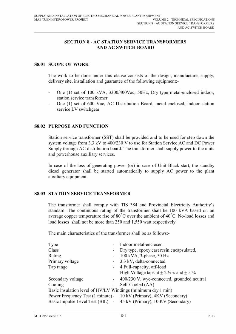
SUPPLY AND INSTALLATION OF ELECTRO-MECHANICAL POWER PLANT EQUIPMENT MAE TUEN HYDROPOWER PROJECT VOLUME 2 - TECHNICAL SPECIFICATIONS
SECTION 8 – AC STATION SERVICE TRANSFORMERS
AND AC SWITCH BOARD
MT-C2V2-sec8/1216 8-1 2013
SECTION 8 - AC STATION SERVICE TRANSFORMERS AND AC SWITCH BOARD
S8.01 SCOPE OF WORK
The work to be done under this clause consists of the design, manufacture, supply, delivery site, installation and guarantee of the following equipment:- - One (1) set of 100 kVA, 3300/400Vac, 50Hz, Dry type metal-enclosed indoor,
station service transformer - One (1) set of 600 Vac, AC Distribution Board, metal-enclosed, indoor station
service LV switchgear
S8.02 PURPOSE AND FUNCTION
Station service transformer (SST) shall be provided and to be used for step down the system voltage from 3.3 kV to 400/230 V to use for Station Service AC and DC Power Supply through AC distribution board. The transformer shall supply power to the units and powerhouse auxiliary services. In case of the loss of generating power (or) in case of Unit Black start, the standby diesel generator shall be started automatically to supply AC power to the plant auxiliary equipment.
S8.03 STATION SERVICE TRANSFORMER The transformer shall comply with TIS 384 and Provincial Electricity Authority’s
standard. The continuous rating of the transformer shall be 100 kVA based on an average copper temperature rise of 80ºC over the ambient of 40ºC. No-load losses and load losses shall not be more than 250 and 1,550 watt respectively.
The main characteristics of the transformer shall be as follows:- Type - Indoor metal-enclosed Class - Dry type, epoxy cast resin encapsulated, Rating - 100 kVA, 3-phase, 50 Hz Primary voltage - 3.3 kV, delta-connected Tap range - 4 Full-capacity, off-load High Voltage taps at + 2 ½ % and + 5 %
Secondary voltage - 400/230 V, wye-connected, grounded neutral Cooling - Self-Cooled (AA) Basic insulation level of HV/LV Windings (minimum dry 1 min) Power Frequency Test (1 minute) - 10 kV (Primary), 4KV (Secondary) Basic Impulse Level Test (BIL) - 45 kV (Primary), 10 KV (Secondary)
SUPPLY AND INSTALLATION OF ELECTRO-MECHANICAL POWER PLANT EQUIPMENT MAE TUEN HYDROPOWER PROJECT VOLUME 2 - TECHNICAL SPECIFICATIONS
SECTION 8 – AC STATION SERVICE TRANSFORMERS
AND AC SWITCH BOARD
MT-C2V2-sec8/1216 8-2 2013
The high voltage bushings shall be connected to Load Break Switch and Lightning arresters as shown in Single Line Diagram. The connection cable to the low voltage bushing terminals of the transformer shall be with 600V power cable. The Contractor shall supply for the required current-carrying capacity and braced for the required fault levels for all phases and neutrals.
Ground Connections The transformer shall have clamp type terminals for connection to the powerhouse
ground system. Clamps and bolts, to accommodate a 95 mm2 stranded cable, shall be provided for ground connections to the transformer core and to 2 points on the transformer enclosure.
Tap Changer The transformer shall be equipped with a selector for off-circuit changing of the taps.
This device shall have a lockable handle and position indicator external to the transformer enclosure.
High Temperature Detection The transformer shall be equipped with oil temperature-sensing element with alarm
contacts and it shall be send status to HMI PLC Monitor for alarm and trip. Auxiliary Power Power from the station battery at 125 V dc (nominal) will be available for transformer
auxiliary circuits. Details of the tests to be performed by the Contractor on the various components of the
equipment shall be stated in the Bid and, in general, shall be as follows. Factory Tests Complete tests on the equipment shall be made at the factory by the manufacturer in
accordance with ANSI standards for oil-immersed, outdoor type transformer, to determine the performance and operating characteristics and to confirm that the equipment functions properly. In addition to these tests, the following test shall be performed.
Standard insulation withstand tests on all small wiring and on all auxiliary devices at
1,500 V to ground, 50 Hz, for 1 minute.
Site Tests
The Contractor shall check the operation of all auxiliary circuits such as gauges, etc.

SUPPLY AND INSTALLATION OF ELECTRO-MECHANICAL POWER PLANT EQUIPMENT MAE TUEN HYDROPOWER PROJECT VOLUME 2 - TECHNICAL SPECIFICATIONS
SECTION 8 – AC STATION SERVICE TRANSFORMERS
AND AC SWITCH BOARD
MT-C2V2-sec8/1216 8-3 2013
The Contractor shall carry out any other tests recommended to prove that the transformer is properly installed and adjusted to operate correctly and safely. Tests shall be in accordance with Provincial Electricity Authority (PEA)’s regulation or ANSI C37.34.
S8.04 HIGH VOLTAGE LOAD INTERRUPTING SWITCH (Not applicable) The high voltage fuse load interrupting switch (3P-PF) shall be 3-pole group operate
for the voltage and basic impulse level specified, and shall be rated for 100-A continuous and 16,000 A interrupting current (momentary). The switches shall be mounted on NEMA rated porcelain insulators for the voltage and basic impulse level specified. Operating mechanism shall include porcelain linkage connections to switch blades with porcelain having a basic impulse level rating at least equivalent to the switch insulators. Switch mechanisms shall be operable externally from the front of cubicle and be equipped with a quick make-and-break device to open and close the switch independently of the speed with which the operating handle is moved. The load break switches shall be capable of closing in on at least 40,000 A asymmetrical fault current without impairing the ability of the switch to carry its full rated continuous current.
Six-pole, auxiliary switch shall be provided for alarm and interlocks. Switch Ratings
SST Interrupting - 100 A, 3-pole, 3.3 kV, 40 kV basic impulse level (minimum) with current limiting fuses
Tests Tests shall be in accordance with ANSI C37.34. The following tests shall be made on each load interrupter switch: - dielectric - short-time current - interrupting - Corona.
S8.05 AUTOMATIC TRANSFER All necessary sensors, relays and controls, etc., shall be provided to automatically
transfer the load to the alternative source upon failure of the normal source. It shall also be possible to connect a diesel generator unit to the LV switchgear.
The preferred source for station service requirement will be the 3.3 kV supply to
transformer (SST) which is fed from the 3.3 kV side of main transformers.
SUPPLY AND INSTALLATION OF ELECTRO-MECHANICAL POWER PLANT EQUIPMENT MAE TUEN HYDROPOWER PROJECT VOLUME 2 - TECHNICAL SPECIFICATIONS
SECTION 8 – AC STATION SERVICE TRANSFORMERS
AND AC SWITCH BOARD
MT-C2V2-sec8/1216 8-4 2013
The automatic transfer and sequence of operation shall be as follows. Refer to Drawing for the station service, single-line diagram.
When transformer SST is de-energized and SST will open, then the diesel generator
set will start. When diesel is up to full speed and voltage required, DG breaker will close to energize.
When normal power is restored from SST breakers, DG breaker will open first and
breaker SST will close to re-energize. The diesel generator will shut down after DG breaker is opened.
The Contractor shall supply all the controls, relays and equipment required to carry out automatic transfer of power sources as described.
Power SST MCCB (DG) Source E E SST X O Diesel gen. O X
Operating Sequence X = closed O = open E = electrically operated Annunciation The following operation shall be annunciated. - Transfer from SST to diesel generator - Return to SST from diesel generator - Blocked auto transfer caused by selector switch in manual or withdrawal of supply
or tie bus breakers.
The annunciation of all the above conditions is primarily to notify the operator of the status of the breakers and shall be alarmed on the control room annunciator.
Test A test switch which located on the main control board shall allow the testing of the
Automatic transfer scheme by simulating an under-voltage condition of the preferred and alternative power source and causing an actual transfer of power sources.
SUPPLY AND INSTALLATION OF ELECTRO-MECHANICAL POWER PLANT EQUIPMENT MAE TUEN HYDROPOWER PROJECT VOLUME 2 - TECHNICAL SPECIFICATIONS
SECTION 8 – AC STATION SERVICE TRANSFORMERS
AND AC SWITCH BOARD
MT-C2V2-sec8/1216 8-5 2013
Selection of Manual Control Placing the selector switch in the manual position shall make the automatic transfer
scheme inoperative and will allow each individual breaker to be operated by its own control switch.
S8.06 NO-FUSE BREAKER No-fuse breakers shall be molded case, manually operated, quick make, and quick
break with both thermal and magnetic trip elements on each pole. All breakers shall be rated for 600V and shall have an interrupting rating not less than 30,000 Arms asymmetrical at 400V.
S8.07 SECONDARY WIRING AND TERMINALS
The switchboards shall be complete with all accessory secondary wiring. All wiring shall be switchboard type stranded copper conductors. Conductor insulation shall be flame-retardant, heat-and moisture-resistant and shall be of the thermoplastic or thermosetting type. The insulation shall be rated at 600 V with a temperature rating of 90ºC.
Wire sizes shall not be less than 6 mm2 for current transformer wiring and 2.5 mm2 for
control, metering, annunciation, and potential circuits. The secondary leads of instrument transformers shall be brought out through test
blocks with molded phenolic covers which have internal plug contacts and make a through connection when the cover is in place. The test block contacts shall be of the live pressure type to provide positive contact with minimum contact resistance and make a through connection when the cover is in place.
The test blocks of current transformers shall be provided with auxiliary contacts which
automatically short circuit the current transformers when the cover or plug is removed. The test block contacts shall be rated 250V, 10A continuous.
All wiring shall be run in plastic wiring duct or shall be formed into compact flat
groups suitably bound together and properly supported. The group shall be run straight, horizontally or vertically, with short-radius right-angle bends. There shall be no splices in the wiring and all connections shall be made at 600V, 25A terminals. Suitable provision shall be made for training and supporting incoming cables from the point of entrance to the termination on the terminal blocks.
All wiring shall be identified at both ends with PVC cable markers which resist grease, oil, acids and abrasion.
The arrangements and locations of all terminal blocks shall be subject to the approval
of DEDE Engineer. Circuit on the terminal blocks shall be marked with permanent

SUPPLY AND INSTALLATION OF ELECTRO-MECHANICAL POWER PLANT EQUIPMENT MAE TUEN HYDROPOWER PROJECT VOLUME 2 - TECHNICAL SPECIFICATIONS
SECTION 8 – AC STATION SERVICE TRANSFORMERS
AND AC SWITCH BOARD
MT-C2V2-sec8/1216 8-6 2013
marking fluid and shall be subject to the approval of the engineer. A minimum of 20 percent spare terminal blocks shall be furnished.
S8.08 CONTROL SWITCHES AND INDICATION One (1) selector switch for selecting Remote and Local Control for the breakers
mentioned above. Indicating Lamps for all phases, annunciator window for Fault and Trip of Breakers
showing clear wording shall be installed in front of Annunciator Window. Mimic Indication in Single Line Diagram in front of AC Distribution Front Door and
the mimic graphic shall be submitted to DEDE for approval.
S8.09 INTERLOCKING
All circuit breakers controlling supply points shall be electrically interlocked to prevent the interconnection of supplies. Breaker auxiliary contacts and auxiliary relays shall be used in the interlocking circuit.
Lockout devices shall be provided if applicable so that if a breaker is tripped by its own over
current protection scheme, other breakers feeding into the same bus cannot be closed. Remote Indication The LV switchgear shall have incorporated in the metering and control circuitry,
provision for remote indication of the followings:-
“Open” “Close”
Circuit Indication
Ammeter
Voltmeter
Voltmeter
Breaker SST X X X Breaker DG X
S8.10 CURRENT TRANSFORMERS Current transformers shall be supplied in each of the transformer secondary breaker
sections of the station service switchboard. The current transformers shall be of the 55ºC rise dry type, used for metering and protective relaying and shall be supplied as follows in accordance with the latest edition of ANSI C57.13 for instrument transformers, or DEDE approved equivalents.
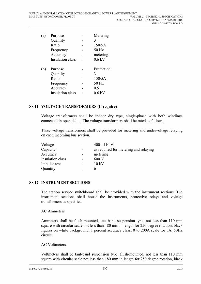
SUPPLY AND INSTALLATION OF ELECTRO-MECHANICAL POWER PLANT EQUIPMENT MAE TUEN HYDROPOWER PROJECT VOLUME 2 - TECHNICAL SPECIFICATIONS
SECTION 8 – AC STATION SERVICE TRANSFORMERS
AND AC SWITCH BOARD
MT-C2V2-sec8/1216 8-7 2013
(a) Purpose - Metering Quantity - 3 Ratio - 150/5A Frequency - 50 Hz Accuracy - metering Insulation class - 0.6 kV (b) Purpose - Protection Quantity - 3 Ratio - 150/5A Frequency - 50 Hz Accuracy - 0.5 Insulation class - 0.6 kV
S8.11 VOLTAGE TRANSFORMERS (If require) Voltage transformers shall be indoor dry type, single-phase with both windings
connected in open delta. The voltage transformers shall be rated as follows. Three voltage transformers shall be provided for metering and undervoltage relaying
on each incoming bus section. Voltage - 400 - 110 V Capacity - as required for metering and relaying Accuracy - metering Insulation class - 600 V Impulse test - 10 kV Quantity - 6
S8.12 INSTRUMENT SECTIONS The station service switchboard shall be provided with the instrument sections. The
instrument sections shall house the instruments, protective relays and voltage transformers as specified.
AC Ammeters Ammeters shall be flush-mounted, taut-band suspension type, not less than 110 mm
square with circular scale not less than 180 mm in length for 250 degree rotation, black figures on white background, 1 percent accuracy class, 0 to 200A scale for 5A, 50Hz circuit.
AC Voltmeters Voltmeters shall be taut-band suspension type, flush-mounted, not less than 110 mm
square with circular scale not less than 180 mm in length for 250 degree rotation, black

SUPPLY AND INSTALLATION OF ELECTRO-MECHANICAL POWER PLANT EQUIPMENT MAE TUEN HYDROPOWER PROJECT VOLUME 2 - TECHNICAL SPECIFICATIONS
SECTION 8 – AC STATION SERVICE TRANSFORMERS
AND AC SWITCH BOARD
MT-C2V2-sec8/1216 8-8 2013
figures on white background, 1 percent (%) accuracy class, 0 to 600 V for 110V, 50-Hz circuit.
Watt Hour Meters or Power Meter Polyphase watt hour meters, for a 3-phase, 4-wire circuit, current transformer rating
900-5 A, voltage transformer rating 400-110 V, 50 Hz, to read and indicate kilowatt hour and kilowatt demand, complete with mechanical demand register, 5 dials, with anti-reverse device for unidirectional operation.
AC Voltmeter Switches Voltmeter switches shall be rotary, panel-mounted type, enclosed contact mechanisms
with removable cover, renewable, self-cleaning, maintained 6 normally open and 6 normally closed contacts, rated 600 V, 20 A continuous, 50-A make and 30-A break at 120 V, 50-Hz inductive load, pistol-grip handle, 4 positions with escutcheon plate engraved “OFF”, 1-2, 2-3, 3-1”, and wired for 3-phase, 4-wire circuit.
Relays - 51, inverse time over current phase consisting of 3 single-phase relays, semiflush
mounting in draw out case - 51N, inverse time over current, semiflush mounting in draw out case It is intended that this relay, upon sensing a ground fault, shall trip the incoming
breaker. If the fault persists it shall then trip 52G. This same sequence of operation shall apply to new Unit.
- 27S, Undervoltage relay for use with automatic transfer scheme, semi flush
mounting in draw out case - Auxiliary relays as required for automatic transfer scheme. The number of instruments and relays which shall be provided for the AC station
switchboard shall be as follows. Frequency meter 1 Wattmeter 2 Ammeters 2 Voltmeters 2 Kilowatt hour meters (or power meter) 1 Voltmeter switches, Ammeter Switch 2 All meters can be use two sets of power meter. 51 relays 3 51 N relays 1 27 relays 2
All meters can also be integrated in Digital Multimeter and provide two sets of power meters.

SUPPLY AND INSTALLATION OF ELECTRO-MECHANICAL POWER PLANT EQUIPMENT MAE TUEN HYDROPOWER PROJECT VOLUME 2 - TECHNICAL SPECIFICATIONS
SECTION 8 – AC STATION SERVICE TRANSFORMERS
AND AC SWITCH BOARD
MT-C2V2-sec8/1216 8-9 2013
All protection relay shall also be combined and in Multifunction Relay and comply relaying functions as per the single line diagram.
S8.13 GROUNDING A grounding copper bus bar not less than 5 mm by 50 mm shall be provided along the
front and rear of the switchgear. The ground bus shall be solidly bolted to the steel framework so as to make good electrical contact. Provisions shall be made at both ends of the switchgear for connection of the ground bus to cables from the station ground mat. Two clamp type terminals suitable for 95-mm2 stranded bare copper conductor shall be provided. All non-current carrying parts shall be connected to the ground bus.
S8.14 NAMEPLATES Nameplates of black background with white lettering and shall be provided for all LV.
Switchgear identifications. Transformer nameplates shall be 22 cm wide by 4 cm high, with letters 19 mm high, centered on the plated.
All nameplates shall be attached to the switchgear with rust-resistant steel, self-tapping
screws. The transformer, switchgear and all switchgear appurtenances shall be identified and all nameplates shall be subject to the DEDE Engineer’s approval.
S8.15 CHANNEL BASES AND BOLTS The Contractor shall provide the foundation bolts and channels necessary for holding
down of fixing the equipment to the concrete foundations. Where the design of the equipment requires special clamps to be used with the foundation bolts, these clamps shall be provided by the Contractor.
S8.16 TESTS The assemblies and their individual components shall be factory and field tested by the
Contractor in accordance with the test specifications outlined herein. Factory Tests The following tests shall be made according to the appropriate standards to ensure
compliance with specifications. Switchgear Assemblies - Standard production tests as specified in NEMA SG 5 and ANSI C37.20 or
approved equivalent

SUPPLY AND INSTALLATION OF ELECTRO-MECHANICAL POWER PLANT EQUIPMENT MAE TUEN HYDROPOWER PROJECT VOLUME 2 - TECHNICAL SPECIFICATIONS
SECTION 8 – AC STATION SERVICE TRANSFORMERS
AND AC SWITCH BOARD
MT-C2V2-sec8/1216 8-10 2013
- Impulse and thermal tests as specified in NEMA SG 5 and ANSI C37.20 or approved equivalent.
Operational Checks - Continuity and polarity tests on all coils and circuits - Functional tests on the automatic under-voltage transfer scheme, and on the over
current protection. Field Tests Such tests shall be carried out in the field, as are necessary in the opinion of the Engineer, for the satisfactory start-up and operation of the apparatus. These will normally comprise - Control and secondary wiring check of complete installation - Dielectric tests on control and secondary wiring using 1,000V megger - Functional tests of the breaker operation, metering, relaying and the automatic
transfer scheme.

SECTION 9
TRANFORMER TERMINAL CUBICLES, GENERATOR TERMINAL CUBICLES,
BUS DUCTS AND NEUTRAL CUBICLES
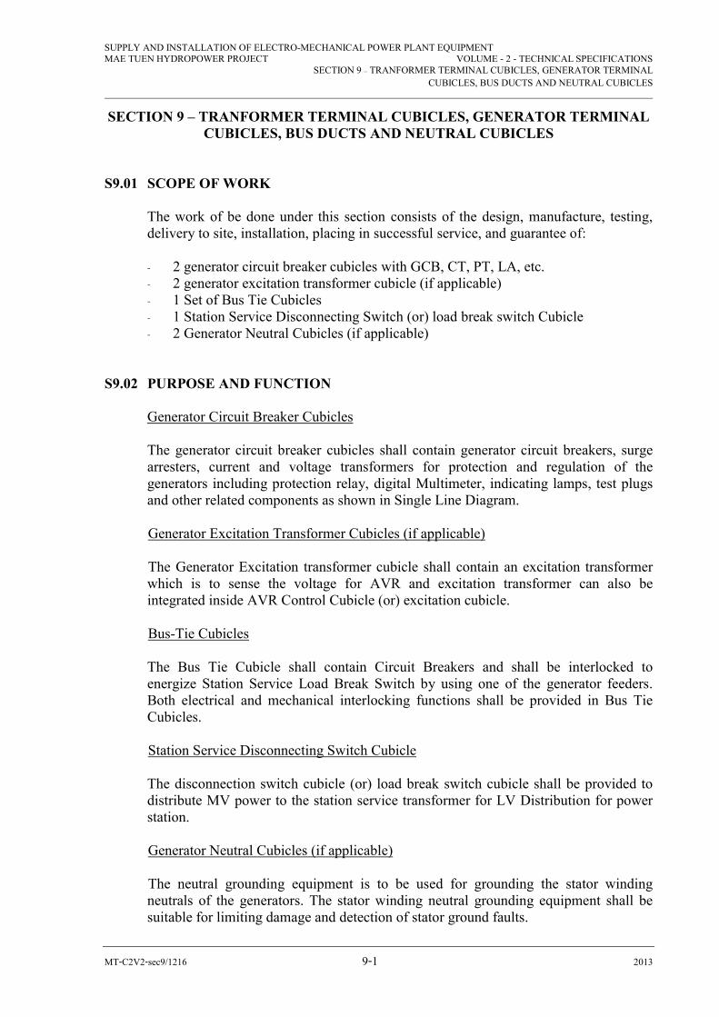
SUPPLY AND INSTALLATION OF ELECTRO-MECHANICAL POWER PLANT EQUIPMENT MAE TUEN HYDROPOWER PROJECT VOLUME - 2 - TECHNICAL SPECIFICATIONS
SECTION 9 – TRANFORMER TERMINAL CUBICLES, GENERATOR TERMINAL
CUBICLES, BUS DUCTS AND NEUTRAL CUBICLES
MT-C2V2-sec9/1216 9-1 2013
SECTION 9 – TRANFORMER TERMINAL CUBICLES, GENERATOR TERMINAL CUBICLES, BUS DUCTS AND NEUTRAL CUBICLES
S9.01 SCOPE OF WORK
The work of be done under this section consists of the design, manufacture, testing, delivery to site, installation, placing in successful service, and guarantee of:
- 2 generator circuit breaker cubicles with GCB, CT, PT, LA, etc. - 2 generator excitation transformer cubicle (if applicable) - 1 Set of Bus Tie Cubicles - 1 Station Service Disconnecting Switch (or) load break switch Cubicle - 2 Generator Neutral Cubicles (if applicable)
S9.02 PURPOSE AND FUNCTION
Generator Circuit Breaker Cubicles
The generator circuit breaker cubicles shall contain generator circuit breakers, surge arresters, current and voltage transformers for protection and regulation of the generators including protection relay, digital Multimeter, indicating lamps, test plugs and other related components as shown in Single Line Diagram.
Generator Excitation Transformer Cubicles (if applicable)
The Generator Excitation transformer cubicle shall contain an excitation transformer which is to sense the voltage for AVR and excitation transformer can also be integrated inside AVR Control Cubicle (or) excitation cubicle. Bus-Tie Cubicles The Bus Tie Cubicle shall contain Circuit Breakers and shall be interlocked to energize Station Service Load Break Switch by using one of the generator feeders. Both electrical and mechanical interlocking functions shall be provided in Bus Tie Cubicles. Station Service Disconnecting Switch Cubicle The disconnection switch cubicle (or) load break switch cubicle shall be provided to distribute MV power to the station service transformer for LV Distribution for power station.
Generator Neutral Cubicles (if applicable)
The neutral grounding equipment is to be used for grounding the stator winding neutrals of the generators. The stator winding neutral grounding equipment shall be suitable for limiting damage and detection of stator ground faults.

SUPPLY AND INSTALLATION OF ELECTRO-MECHANICAL POWER PLANT EQUIPMENT MAE TUEN HYDROPOWER PROJECT VOLUME - 2 - TECHNICAL SPECIFICATIONS
SECTION 9 – TRANFORMER TERMINAL CUBICLES, GENERATOR TERMINAL
CUBICLES, BUS DUCTS AND NEUTRAL CUBICLES
MT-C2V2-sec9/1216 9-2 2013
S9.03 STANDARDS The equipment and accessories shall be designed, manufactured and tested where
applicable, in accordance with the following standards, codes or approved equivalent standards.
Requirements, Terminology and Test IEEE 32 Procedure for Neutral Grounding Devices
High Voltage Metal Enclosed Switchgear and Control Gear IEC 62271-200 S9.04 GENERATOR CIRCUIT BREAKER CUBICLES AND BUS DUCTS RATINGS The generator circuit breaker cubicles shall be of metal-enclosed construction in
accordance with the requirements of IEC 62271-200, unless otherwise stated herein. Type test report and calculation for selection of the proposed switchgear and generator circuit breaker shall be submitted together with the Bid.
The rating of the Generator Circuit Breaker cubicles, Bus Tie Cubicles and their
related accessories shall be as follows:
- Voltage 7.2kV (or) more
- Frequency 50 Hz
- Phases 3
- System 3-wire delta
- Continuous current (minimum) 2000 A (minimum)
- Short-time (3 seconds) current 31,500 Arms asymmetrical
- Momentary (1 second) current 31,500 Arms asymmetrical
- Standard low frequency (50 Hz) 38,000 Vrms
insulation withstand strength
- Standard 1.2 by 50 µs, full-wave impulse 95 kV crest
withstand strength
- Temperature rise (above 40ºC ambient 65ºC indoor
outside of the enclosure for the generator
terminal cubicles)
S9.05 EQUIPMENT DETAILS Generator Circuit Breaker Cubicles The Contractor shall supply two generator circuit breaker cubicles for Generating Unit
1 and 2, and each shall consist of the followings:-

SUPPLY AND INSTALLATION OF ELECTRO-MECHANICAL POWER PLANT EQUIPMENT MAE TUEN HYDROPOWER PROJECT VOLUME - 2 - TECHNICAL SPECIFICATIONS
SECTION 9 – TRANFORMER TERMINAL CUBICLES, GENERATOR TERMINAL
CUBICLES, BUS DUCTS AND NEUTRAL CUBICLES
MT-C2V2-sec9/1216 9-3 2013
Quantity Description
2 sets A type tested metal-clad switchgear (comprising of Circuit breaker compartment, LV Control compartment, Busbar compartment and Cable Compartment) shall be supplied to house the withdrawable circuit breaker, voltage transformers, current transformers, surge arresters, relays, digital Multimeter with related accessories/ components with ratings as stated in this section and Single Line Diagram to serve the same function for measuring, protection and regulation.
Type SF6 (or) VACUUM TYPE
Voltage 7.2kV
Frequency 50 Hz
Continuous current 2000 A
Interrupting capacity at 7.2 kV 31.5 kA
Short-time (4 s) withstand 31,500 Arms asymmetrical
strength
Short-time (momentary) 31,500 Arms asymmetrical
withstand strength
Breaker Operating Voltage 125 V DC supply
6 ea. Current transformers for metering, protection and regulation, single phase, dry type and shall have the ratings as below: -
- Ratio 100/5/5A and 100/5A - Accuracy 0.5 and C200 - Capacity to be specified by Contractor
6 ea. Voltage transformers for metering, protection and synchronizing, single-
phase, dry type and shall have the ratings as below: -
- Ratio 3.3/ kV/ 110/ / 110/
- Capacity To be specified by Contractor
- Accuracy 0.5 and C200
- Basic impulse level 40 kV
3 ea. Lightning arrester, gapless type
In case of CT, PT and LA are not suitable (or) not enough space to house inside
Generator Circuit Breaker Cubicle, the Contractor shall provide separate CT, PT and
LA cubicle for each Unit.
Buses and Cable connections for the generator circuit breakers, voltage transformers,
current transformers, surge arresters, excitation transformers (if applicable), and
ratings stated in this section complying with the reputable standards specified herein.
Sufficient quantity of terminal boards to accommodate external wiring required.
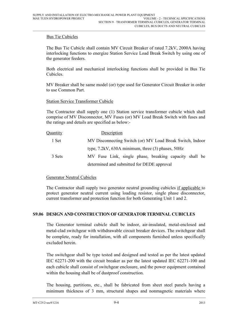
SUPPLY AND INSTALLATION OF ELECTRO-MECHANICAL POWER PLANT EQUIPMENT MAE TUEN HYDROPOWER PROJECT VOLUME - 2 - TECHNICAL SPECIFICATIONS
SECTION 9 – TRANFORMER TERMINAL CUBICLES, GENERATOR TERMINAL
CUBICLES, BUS DUCTS AND NEUTRAL CUBICLES
MT-C2V2-sec9/1216 9-4 2013
Bus Tie Cubicles
The Bus Tie Cubicle shall contain MV Circuit Breaker of rated 7.2kV, 2000A having interlocking functions to energize Station Service Load Break Switch by using one of the generator feeders. Both electrical and mechanical interlocking functions shall be provided in Bus Tie Cubicles. MV Breaker shall be same model (or) type used for Generator Circuit Breaker in order to use Common Part.
Station Service Transformer Cubicle
The Contractor shall supply one (1) Station service transformer cubicle which shall comprise of MV Disconnector, MV Fuses (or) MV Load Break Switch with fuses and the ratings and details are specified as below:-
Quantity Description
1 Set MV Disconnecting Switch (or) MV Load Break Switch, Indoor
type, 7.2kV, 630A minimum, three (3) phases, 50Hz
3 Sets MV Fuse Link, single phase, breaking capacity shall be
determined and submitted for DEDE approval
Generator Neutral Cubicles The Contractor shall supply two generator neutral grounding cubicles if applicable to
protect generator neutral current using loading resistor, single phase disconnector, current transformer and protection function for both Generating Unit 1 and 2.
S9.06 DESIGN AND CONSTRUCTION OF GENERATOR TERMINAL CUBICLES
The Generator terminal cubicle shall be indoor, air-insulated, metal-enclosed and
metal-clad switchgear with withdrawable circuit breaker devices. The switchgear shall
be complete, ready for installation, with all components furnished unless specifically
excluded herein.
The switchgear shall be type tested and designed and tested as per the latest updated
IEC 62271-200 with the circuit breaker as per the latest updated IEC 62271-100 and
each cubicle shall consist of switchgear enclosure, and the power equipment contained
within the housing shall be of dustproof construction.
The housing, partitions, etc., shall be fabricated from sheet steel panels having a
minimum thickness of 3 mm, structural shapes and nonmagnetic materials where

SUPPLY AND INSTALLATION OF ELECTRO-MECHANICAL POWER PLANT EQUIPMENT MAE TUEN HYDROPOWER PROJECT VOLUME - 2 - TECHNICAL SPECIFICATIONS
SECTION 9 – TRANFORMER TERMINAL CUBICLES, GENERATOR TERMINAL
CUBICLES, BUS DUCTS AND NEUTRAL CUBICLES
MT-C2V2-sec9/1216 9-5 2013
required, in such a manner that the complete structure shall be rigid, self-supporting
and free from magnetic vibration, twist and weave.
The switchgear shall have 4 compartments that are Busbar compartment, circuit
breaker compartment, Medium Voltage Cable compartment and Low voltage
compartment. There shall be a partition to separate each Busbar compartment between
the adjacent compartments.
The shutter between circuit breaker and Busbar compartment shall be made of metal.
All sheet steel panels used in the construction of the walls, partitions, hinged doors and
removable panels, etc., shall be adequately supported and stiffened to prevent flexing
and excessive vibration.
Each cubicle shall be provided with a steel channel base frame with provision for
bolting it to the concrete floor and placed adjacent to the panel of the station service
transformer cubicle. The switchgear shall be of the same type and model for
transformer and generator circuit breaker cubicles.
An opening shall be provided in the bottom of the housing to permit the entrance of
instrument transformer secondary and miscellaneous cables which will be terminated
in the auxiliary compartment.
An electric heater to prevent condensation shall be provided in accordance with
Clause S1.23 (10).
The Contractor shall be responsible for the coordination, proper physical fit and other
interfacing functions, including the location and phasing of bus terminations. The
surge protectors, voltage transformers, 3.3 kV buses and bus connections in each
cubicle shall be installed in cable compartment of the same panel and the auxiliary
compartment shall be provided containing the voltage test devices, voltage transformer
secondary fuses, current test link blocks and termination boards.
A hinged door shall be provided on the front of the auxiliary compartment. All hinged
doors shall be equipped with semi-concealed highs and suitable locks. Similar locks
shall also be provided on the voltage transformer drawers.
All compartment doors shall be so constructed that they will not seize in the event of a
fire within the cubicle.
Ventilating louvers shall be provided in the hinged doors, and in other locations where
required, to prevent undue temperature rise. The ventilating louvers in the hinged
doors and in other locations of the housing shall have openings small enough to

SUPPLY AND INSTALLATION OF ELECTRO-MECHANICAL POWER PLANT EQUIPMENT MAE TUEN HYDROPOWER PROJECT VOLUME - 2 - TECHNICAL SPECIFICATIONS
SECTION 9 – TRANFORMER TERMINAL CUBICLES, GENERATOR TERMINAL
CUBICLES, BUS DUCTS AND NEUTRAL CUBICLES
MT-C2V2-sec9/1216 9-6 2013
prevent the entrance of rodents and insects. Openings between adjacent compartments
for ventilation purposes will not be permitted.
Entrance bushings shall be used for insulating and supporting the buses and bus
connections that pass from 1 compartment into another. Where the use of bushings is
not practical due to space limitations, panels of approved insulating materials may be
used instead for this purpose. The arrangement chosen shall ensure a reasonably tight
seal between compartments.
All materials used in the cubicles, such as bus insulation, bus supports, etc., shall not
independently support combustion.
Equipment and connections within each compartment shall have their mounting bolts
arranged so that it will be possible to replace them without removing from service
equipment in adjacent compartments.
The voltage transformers shall be mounted on smooth-rolling, draw-out carriages. The
voltage transformers shall be single-phase, and each voltage transformer shall be
furnished with primary current-limiting fuse.
Provision shall be made for a maintenance check on the primary contact alignment of
the voltage transformers by providing a wire-glass window (s) in the back plate that
can view the voltage transformer and fuses.
The voltage transformers and fuses shall be completely disconnected and visibly
grounded when in position to permit inspection or to permit access for removal or
replacement of fuses.
The voltage transformer core shall not saturate at voltages lower than 110 percent of
system voltage. The voltage transformer assembly shall have provision for padlocking
in the disconnected position, and it shall be possible to close the outer door with the
voltage transformers left in the disconnected position.
The buses and bus connections shall be of copper bar, and supported on suitable
insulators and properly braced to withstand the short-circuit forces. The bus bars shall
be fully insulated throughout and also at tap-off points using flame-retardant, track-
resistant, non-hygroscopic materials.
Joints between bus sections, etc. shall have their contact surfaces silver-plated, and
shall be fastened with bolts, nuts and locking devices.
Bus bar supports between panels shall be tightly sealed between compartments.
Means of linear expansion shall be provided.
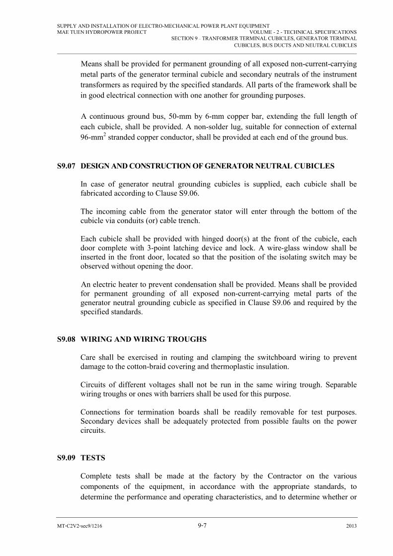
SUPPLY AND INSTALLATION OF ELECTRO-MECHANICAL POWER PLANT EQUIPMENT MAE TUEN HYDROPOWER PROJECT VOLUME - 2 - TECHNICAL SPECIFICATIONS
SECTION 9 – TRANFORMER TERMINAL CUBICLES, GENERATOR TERMINAL
CUBICLES, BUS DUCTS AND NEUTRAL CUBICLES
MT-C2V2-sec9/1216 9-7 2013
Means shall be provided for permanent grounding of all exposed non-current-carrying
metal parts of the generator terminal cubicle and secondary neutrals of the instrument
transformers as required by the specified standards. All parts of the framework shall be
in good electrical connection with one another for grounding purposes.
A continuous ground bus, 50-mm by 6-mm copper bar, extending the full length of
each cubicle, shall be provided. A non-solder lug, suitable for connection of external
96-mm2 stranded copper conductor, shall be provided at each end of the ground bus.
S9.07 DESIGN AND CONSTRUCTION OF GENERATOR NEUTRAL CUBICLES In case of generator neutral grounding cubicles is supplied, each cubicle shall be
fabricated according to Clause S9.06. The incoming cable from the generator stator will enter through the bottom of the
cubicle via conduits (or) cable trench. Each cubicle shall be provided with hinged door(s) at the front of the cubicle, each
door complete with 3-point latching device and lock. A wire-glass window shall be inserted in the front door, located so that the position of the isolating switch may be observed without opening the door.
An electric heater to prevent condensation shall be provided. Means shall be provided
for permanent grounding of all exposed non-current-carrying metal parts of the generator neutral grounding cubicle as specified in Clause S9.06 and required by the specified standards.
S9.08 WIRING AND WIRING TROUGHS Care shall be exercised in routing and clamping the switchboard wiring to prevent
damage to the cotton-braid covering and thermoplastic insulation. Circuits of different voltages shall not be run in the same wiring trough. Separable
wiring troughs or ones with barriers shall be used for this purpose. Connections for termination boards shall be readily removable for test purposes.
Secondary devices shall be adequately protected from possible faults on the power circuits.
S9.09 TESTS Complete tests shall be made at the factory by the Contractor on the various
components of the equipment, in accordance with the appropriate standards, to
determine the performance and operating characteristics, and to determine whether or

SUPPLY AND INSTALLATION OF ELECTRO-MECHANICAL POWER PLANT EQUIPMENT MAE TUEN HYDROPOWER PROJECT VOLUME - 2 - TECHNICAL SPECIFICATIONS
SECTION 9 – TRANFORMER TERMINAL CUBICLES, GENERATOR TERMINAL
CUBICLES, BUS DUCTS AND NEUTRAL CUBICLES
MT-C2V2-sec9/1216 9-8 2013
not the guarantees have been met. The following tests shall be included for each of the
components as outlined below.
Generator Circuit Breaker Cubicles
- Mechanical operation of all components to ensure that all parts operate properly.
- Electrical operation and continuity tests of all circuits and isolating switches.
- Standard 50-Hz insulation withstand test of each switchgear assembly at 19kVrms
for 1 minute. The voltage transformers may be disconnected for this test, but shall
be subjected to individual tests as covered by the applicable standards.
- Standard 1.2 by 50-microsecond full-wave impulse withstand tests at 60 kV crest
on one of each representative switchgear assemblies. The voltage transformers
shall be left connected for this test.
- Standard temperature test on one representative generator terminal cubicle only.
Qualification and factory tests on voltage transformers shall be in accordance with
ANSI C57.13.
The factory tests shall be made on each voltage transformer including type test and
routine test reports shall be submitted to DEDE for approval before delivery.
SECTION 10
DC STATION SERVICES

SUPPLY AND INSTALLATION OF ELECTRO-MECHANICAL POWER PLANT EQUIPMENT MAE TUEN HYDROPOWER PROJECT VOLUME 2 - TECHNICAL SPECIFICATIONS
SECTION 10 – DC STATION SERVICES
MT-C2V2-sec10/1216 10-1 2013
SECTION 10 - DC STATION SERVICES
S10.01 SCOPE OF WORK
The work to be done under this section consists of the design, manufacture, testing,
delivery to site, installation placing in successful service and guarantee of: -
- 1 (one) 125-V battery with racks and fuses, 300 AH minimum
- 1 (one) Battery Charger
- 1 (one) DC distribution panel board with instruments and circuit breakers
S10.02 PURPOSE AND FUNCTION
The DC station service system, comprising of Lead-acid vented type battery, battery
charging equipment and dc distribution panel board, shall be used for PLC
Controlled Automation System, Protection, Monitoring and Alarm System, Turbine
Governing System, Lubricating Oil System, Motor Control Centers, MV and LV
Switchgear, 22kV Switchyard Equipment, Annunciator System, emergency lighting
and other essential DC loads which are to be used during shutdown and start-up of
the generating unit.
S10.03 BATTERY
The batteries shall be 125-V, lead-acid vented type in shock-absorbing, translucent
polypropylene plastic containers, in order to check the electrolyte level and
manufacturer shall be certified according to ISO 9001 series quality standard
complete with intercell connectors and standard accessories.
Each battery shall consist of number of cells for total minimum capacity 300 AH, 10
hrs rated with the following sequence of operation during trip, shutdown and start-up
of the generating unit as minimum: -
- Both generator breakers and one-line breakers (total 3) trip simultaneously.
- Generator and line breakers reclosing sequentially.
- Both reclosed breakers trip simultaneously.
- No generation or other AC Supply is not available for 5 hours.
- Emergency Lamp for 5 hours.
- Indicating lamps, annunciation inside Control Room
- Continuous DC Supply for PLC Control Panels, HMI PC, Touch Screens,
Printers, Modems, Routers, etc.
SUPPLY AND INSTALLATION OF ELECTRO-MECHANICAL POWER PLANT EQUIPMENT MAE TUEN HYDROPOWER PROJECT VOLUME 2 - TECHNICAL SPECIFICATIONS
SECTION 10 – DC STATION SERVICES
MT-C2V2-sec10/1216 10-2 2013
This duty cycle, together with an allowance of 10 percent for design margin, shall be
used as a minimum to determine the battery capacity.
Bidder shall submit the Battery and Battery Charger Sizing according to IEEE 485-
“Recommended Practices for Sizing Lead Acid Batteries for Stationary
Applications” and the Design Load Profile and Calculated Battery and Charger
Sizing shall be submitted with the Bid verifying the proposed capacity is enough for
equipment supplied under this contract.
The battery (lead-acid) shall have a capacity to supply the duty cycle given above,
without assistance from the charging source and without the battery dropping below
1.8 Volts/cell. The battery (lead-acid) shall be constructed using the best industry
practice. It shall have the polarity permanently and legibly marked on each terminal
or on the cover adjacent to the terminal.
The battery shall be supplied complete with lead-covered copper intercell and
connector ratings shall suit the maximum discharge current of the battery.
Cells shall have sufficient sediment space so that cleaning during the normal life of
the battery may be avoided.
S10.04 BATTERY RACKS
Freestanding steel battery racks with lead-liner trays shall be provided for supporting
the complete battery. The racks shall have a maximum of 2-3 tiers. They shall be
sized and arranged to allow sufficient clearance for battery maintenance inside the
battery room.
The battery racks shall be constructed from angle steel. The trays shall be fabricated
from sheet steel and lined with sheet lead.
All surfaces shall be free from sharp edges and burrs, and the trays free from dents
and bulges.
The lining of each tray shall be so fabricated that it overlaps the edges of the tray,
and the only joints shall be at the corners. These joints shall be watertight.
S10.05 INSTRUMENTS ON DC DISTRIBUTION BOARD
The DC station service installation shall include a panel for the followings:
- DC ammeters complete with shunt and fuses (to measure total DC load and
battery current)

SUPPLY AND INSTALLATION OF ELECTRO-MECHANICAL POWER PLANT EQUIPMENT MAE TUEN HYDROPOWER PROJECT VOLUME 2 - TECHNICAL SPECIFICATIONS
SECTION 10 – DC STATION SERVICES
MT-C2V2-sec10/1216 10-3 2013
- Non-automatic circuit breaker to disconnect battery from load
- Voltmeter and fuses to measure battery voltage
- Undervoltage relay to detect loss of dc with an ac alarm contact
- Ground detective relay with an alarm contact.
S10.06 BATTERY CHARGER
The battery charger shall be fully automatic, rectifier controlled design for automatic
float and boost charging of batteries, to be enclosed inside a metal cabinet suitable
for floor mounting. The charger is to supply DC at constant voltage for the average
dc powerhouse load and for maintaining the battery, connected in parallel with the
load, in a fully charged floating state. The ac supply source will be single-phase, 230-
V nominal rating, 50 Hz.
Voltage regulation shall be +1 percent, with ac supply voltage variation of 10 percent
and frequency variation of 5 percent from 0 to full load of the charger.
The nominal output of the charger shall be 125 V dc, with the battery voltage range
of 105 V to 140 V dc.
The equipment shall be of the static type, with no moving parts. It shall be equipped
with automatic float-equalizer, 28-d timer and with protection against sudden line
voltage variations. Protection shall also be provided against damage due to overload.
The charger shall be connected with PLC Controller by using LAN (or) RS 232 (or)
RS 485 cable to send the real time status of information about the battery, charger
and load information.
The charger shall have manual switching to the high rate charge mode. Switching
from high rate to float charge mode shall be automatic.
The charger shall be equipped with the following protective devices.
- Circuit breaker with thermal magnetic trip unit for dc output. The minimum
interrupting capacity of the breaker shall be 10,000 A DC. Its current rating shall
be 1.5 to 2.0 times the charger rated current.
- A reverse current limiting device to protect the battery in the event of ac failure.
- Annunciator Lamps shall show indication under the following conditions:-
. Opening of the DC output breaker
. Failure of the ac supply
. Loss of charger control voltage
. Battery charger failure
. DC output undervoltage
. AC output overvoltage
SUPPLY AND INSTALLATION OF ELECTRO-MECHANICAL POWER PLANT EQUIPMENT MAE TUEN HYDROPOWER PROJECT VOLUME 2 - TECHNICAL SPECIFICATIONS
SECTION 10 – DC STATION SERVICES
MT-C2V2-sec10/1216 10-4 2013
- Each of the annunciator circuits shall be wired to terminal blocks for connection
to a remotely located annunciator. Alarms at the charger are not required.
The charger shall automatically return to service on restoration of ac supply after an
interruption.
Indicating lamps equipment status indications shall be provided.
All relays supplied shall be of the dustproof type.
The battery charger and auxiliary equipment shall be contained in a single, general
purpose, ventilated enclosure, suitable for floor mounting indoors. The enclosure
shall be fabricated from sheet steel panels. It shall be rigid, self-supporting and free
from magnetic vibration, twist and weave. All panels used in the construction of the
enclosure including partitions and doors shall be adequately supported and stiffened
where necessary to prevent flexing.
Components shall be arranged within the enclosure, with access via a hinged front
door, for convenient inspection and maintenance and for making external
connections.
Meters, indicating lamps and other externally accessible devices shall be located for
convenient viewing or operation.
A copper clamp type connector having a conductor range of 25 mm2 shall be bolted
to the enclosure for connection to the station ground system.
The enclosure shall have a nameplate giving charger input and output ratings and
other pertinent information.
Identification tapes, Dymo embossing type, 13 mm wide or equivalent, shall be used
for identifying fuses.
S10.07 DISTRIBUTION PANEL BOARD
The distribution panel board shall be suitable for floor mounting. The panel board
shall have sufficient capacity for containing a main circuit breaker and up to thirty 2-
pole branch breakers. The panel board shall have a voltage rating of 250 V dc and a
short circuit capacity of 10,000ADC. Its current-carrying capacity shall be sized for
the maximum discharge capacity of the battery and shall be a minimum of 400 ADC.

SUPPLY AND INSTALLATION OF ELECTRO-MECHANICAL POWER PLANT EQUIPMENT MAE TUEN HYDROPOWER PROJECT VOLUME 2 - TECHNICAL SPECIFICATIONS
SECTION 10 – DC STATION SERVICES
MT-C2V2-sec10/1216 10-5 2013
The main breaker shall be a molded case type, 2-pole. It shall have a voltage rating
of 250 V dc and an interrupting capacity of 10,000 A DC. Its frame size shall be
rated to suit the maximum discharge capacity of the battery and shall be a minimum
of 400 ADC. This breaker shall have a thermal magnetic trip unit.
The panel board shall have 30 branch circuit breakers, molded case type, 2-pole,
each with a thermal magnetic trip unit and 1 set of Form C auxiliary contacts. Each
breaker shall have a voltage rating of 250 V DC, an interrupting capacity of 10,000 A
DC and a frame size of 100 A DC.
The breaker trip ratings are provisional. The Contractor shall determine final ratings
according to design requirements.
The main and branch breaker auxiliary switches shall be wired to separate terminal
blocks. The normally closed auxiliary contacts of the branch breakers shall be
connected in parallel and wired to 1 pair of terminal blocks. The contacts of each
spare breaker shall be wired to 1 set of terminals.
S10.08 CABLE INTERCONNECTION
The Contractor shall supply properly sized cables between the battery, the instrument
panel and the battery charger. The Contractor shall also supply and coordinate cable
size between the battery circuit breaker and the distribution panel.
S10.09 TESTS
Complete tests on the equipment shall be made at the factory be the Contractor to
determine the performance and operating characteristics and to confirm that the
equipment function properly. Details of the tests to be performed on the various
components of the equipment shall be submitted, and the following tests shall be
done as follows:-
Battery Charger
- Mechanical operation of the components to ensure that all parts operate
properly.
- Standard insulation withstand tests on all circuit breakers, relays, switches and
other devices and on all wiring at 1,500 V to ground, 50 Hz for 1 minute.
- Continuity and polarity test on all circuits.
- Functional and operational checks of all equipment and all control, metering
and protection circuits.
- Load simulation under various input voltages from 180 V to 230 VAC.

SUPPLY AND INSTALLATION OF ELECTRO-MECHANICAL POWER PLANT EQUIPMENT MAE TUEN HYDROPOWER PROJECT VOLUME 2 - TECHNICAL SPECIFICATIONS
SECTION 10 – DC STATION SERVICES
MT-C2V2-sec10/1216 10-6 2013
Distribution Panel board, Instrument Panel and Circuit Breakers
- Mechanical operation of all circuit breakers to ensure that they operate
properly.
- Standard insulation withstands tests on all circuit breakers and on all wiring at
1,500 V to ground, 50 Hz for 1 minute.

SECTION 11
CONTROL, PROTECTION AND ALARM SYSTEM

SUPPLY AND INSTALLATION OF ELECTRO-MECHANICAL POWER PLANT EQUIPMENT MAE TUEN HYDROPOWER PROJECT VOLUME 2 - TECHNICAL SPECIFICATIONS
SECTION 11 – CONTROL, PROTECTION AND ALARM SYSTEM
MT-C2V2-sec11/1216 11-1 2013
SECTION 11 - CONTROL, PROTECTION AND ALARM SYSTEM
S11.01 GENERAL
(1) Responsibilities
a) The Contractor shall design, supply, procure, delivery to site, installation,
testing and commissioning the control; monitoring and protection system
for the turbine, generator, governor, transformers, switchgears and other
related station auxiliaries including all interfaces and associated equipment.
b) The contractor shall supply, deliver, install, testing and commission all
control, protection and alarm system equipment and have overall
responsibility for successful start-up, commissioning of turbine-generator
units, governor, inlet valves, transformers, MV switchgears and other
station auxiliaries which are to be supplied under this contract.
c) For Protection, Metering and Alarm System, the Bidder shall provide
overall electrical single line diagram with complete relay numbers, meters
for electrical protection and metering according to ANSI, IEC and IEEE
Codes and the description detail for the Bidder’s proposed system to be
submitted together with Bid.
For Control, Monitoring and Alarm System, the Bidder shall submit
together with the Bid for Control and Monitoring System Configuration
Diagram together with Normal Start, Stop and Emergency Shutdown
Sequence for Unit as well as logic diagram (or) flow diagram for
Generating Unit Operation.
d) Equipment and Components, which are to be used in Automation Control
System, shall be submitted in the Bid together with manufacturer’s product
catalogs such as PLC CPU modules with redundancy, I/O modules, Power
Supply Modules, Ethernet Modules, HMI Touch Screen, Notebook and
Controller Chassis together with Licensed Software used for controlling
and monitoring of Generating Unit operation.
e) The protection system of the station of based on the principle of local back
up. In other terms, any fault occurring anywhere on generator feeders,
outgoing line, line transformer or on bus bar shall be detected and cleared
locally by relays and breakers located in the substation (or) switchyard. In
the event of failure of battery, instruments or relays, the system should
detect and enable to clear all failures of equipment.

SUPPLY AND INSTALLATION OF ELECTRO-MECHANICAL POWER PLANT EQUIPMENT MAE TUEN HYDROPOWER PROJECT VOLUME 2 - TECHNICAL SPECIFICATIONS
SECTION 11 – CONTROL, PROTECTION AND ALARM SYSTEM
MT-C2V2-sec11/1216 11-2 2013
(2) Requirements for Systems
a) Each system shall be designed to have high reliability and availability and
however it shall be simple to operate and maintain by DEDE operator. The
failure of any equipment or the loss of power supply to equipment shall
not jeopardize the plant and shall initiate an alarm.
b) The normal control shall be operated at operator control station in the
control room and for the purpose of system maintenance, commissioning
or testing, it shall be done by via both engineering PLC and local control
graphical HMI Touch Screen at Governor PLC control panel.
c) The control system shall comprise a number of programmable logic
controllers (PLC), a digital PLC governor system, an excitation with
digital automatic voltage regulator (AVR), a digital protective relay and
synchronizing system. This PLC shall be connected to the human-machine
interface (HMI) via of data communication cable. The metering and
instrumentation of equipment and the related system shall be provided
information for operator including annunciation system.
d) The operation for Generating Sets shall be by both automatic mode and
local manual mode. A typical automatic mode shall be a programming
control sequence stored and programmed in the PLCs. The control
functions shall be included supervising, controlling and monitoring to the
unit conditions, recording the sequence of events, periodically fault and
alarm events, providing integration of historical trending display, bar chart
display and guidance messages.
The Bidder shall submit PLC Manufacturer’s Letter of Confirmation for PLC
Control System stating that the PLC manufacturer will design, supply and
supervision for commissioning start-up and guarantee performance for their
Supplied Products with Licensed Software complying with DEDE Specifications
specified under this section 11.
The scope of supply for PLC control system of this power station shall be to
control and monitoring of two (2) Sets of generating unit with station auxiliaries
and it shall be comprised of the following equipments.
(a) Operator Control Station 1 Set (Including software same brand name with
PLC to control operate the TG unit and Dongle or USB key licensed)
(b) Laptop/ Notebook computer (Industrial Type) for engineering work station
1 set (Including Dongle or USB key license software tool for engineering
work station notebook to adjust or modified system configuration,
SUPPLY AND INSTALLATION OF ELECTRO-MECHANICAL POWER PLANT EQUIPMENT MAE TUEN HYDROPOWER PROJECT VOLUME 2 - TECHNICAL SPECIFICATIONS
SECTION 11 – CONTROL, PROTECTION AND ALARM SYSTEM
MT-C2V2-sec11/1216 11-3 2013
changing parameters and to perform commissioning and testing for the
unit)
(c) Programmable logical controller (PLC) with software in unit control PLC
cubicle for each unit and shall be comprised of:
- Redundant central processing units (CPU), power supply modules,
IO Modules and Communication Modules
- Redundant Digital Excitation System for each unit
- Redundant Ethernet Bus to communicate and control Digital
Governor
- Redundant Ethernet Bus to communicate and control multifunction
protective relays & all meters
- Redundant Ethernet Bus to communicate and control with
Excitation system
- Redundant Ethernet Bus to communicate and control
Synchronization unit
- I/O modules to interface with equipments to perform unit control
function
- HMI Touch Panels with 12” screen (Built-in two (2) individual
Ethernet port) same brand name with PLC Controller for both Unit
PLC and Governor PLC for local operation.
- Interfacing ports with engineering station (Notebook Computer)
- Licensed Software for Governor and Unit PLCs, which shall be
same Brand with PLC Module manufacturer.
(d) Automatic Synchronization including synchroscope completed with
accessories 1 set
(e) Digital protective relay system two (2) sets including software for
engineering laptop
(f) Local Area Network (LAN) System including switching hubs 1 lot
(Including interfacing port)
(g) Metering, instruments and annunciation display unit including transducers
for two (2) generating sets, auxiliary and switchyard equipment.
(h) Periphery equipment such as 2 sets of LCD monitor (24" or Larger), 1 Set
of Laser Printer (with LAN Port), 1 set of operator control desk (heavy
duty type, steel structure construction) with chairs, etc.

SUPPLY AND INSTALLATION OF ELECTRO-MECHANICAL POWER PLANT EQUIPMENT MAE TUEN HYDROPOWER PROJECT VOLUME 2 - TECHNICAL SPECIFICATIONS
SECTION 11 – CONTROL, PROTECTION AND ALARM SYSTEM
MT-C2V2-sec11/1216 11-4 2013
(i) All design documents and drawings including equipment sizing,
calculations, relay coordination study, relay settings, system block
diagrams, layout; schematics; and wiring diagrams.
(j) Logic flow charts or descriptions for control sequences.
(k) Control system input and output lists
(l) Alarm list
(m) Format of predefined reports
Bidder shall submit the complete information and documents with the Bid
indicating all scopes, component model/ type complying with the requirements
as stated in this section clearly submitting all related evidences to verify that the
Proposed Control System meets the DEDE requirements.
Failure to comply, submit, indicate the required items in this clause will subject
to rejection of the Bidder Proposal.
(n) Branch circuits for each function shall be individually protected. Provision
shall be made to enable isolation of each circuit separately.
(o) Control, annunciation, alarm and protection circuits shall operate at
125VDC and the consumable capacity for Battery and charger sizing
calculation shall be submitted with the Bid.
(p) All indicating and pilot lamps shall be of the low power, cool operating
with DC, switchboard type, with color caps and mounted resistors
integrally. All indicating lights shall be suitable for operating at 125 V DC.
(3) Requirements for Devices
(a) Programmable Logic Controller (PLC)
A programmable logical controller shall be a well-proven 32-bit processor
design with wide range of I/O modules accepting discrete, analog and RTD
inputs and shall have flash card for data and parameter storage. The PLC
shall provide on-board self-diagnostics, with on-board LED indicators
defining processor controller status. As a minimum, the process controller
shall support the following attributes:
- Built-in minimum RAM 64MByte and Flash 64MByte
- Processor speed minimum 1GHz
SUPPLY AND INSTALLATION OF ELECTRO-MECHANICAL POWER PLANT EQUIPMENT MAE TUEN HYDROPOWER PROJECT VOLUME 2 - TECHNICAL SPECIFICATIONS
SECTION 11 – CONTROL, PROTECTION AND ALARM SYSTEM
MT-C2V2-sec11/1216 11-5 2013
- Built-in One RS-485 port and one RS-232 port
- Analog loop shall be processed at operator tunable rate down to 10
times per second
- Binary loop shall be processed at operator tunable rate down to 10
times per second
- A full range of preconfigured algorithms that can be used to
implement control strategies
- Capable of being configured in ladder logic or capable of executing
higher level programming languages such as BASIC, C or capable of
executing operator-defined functions not included in the standard
function
- Capable of executing any combination of the above functions, i.e.,
Standard algorithms, ladder, higher level programming languages, etc.
- Capable of peer-to-peer communication with any of additional
Operator Control Stations and every other module in the system
- Support Ethernet TCP/IP communication to Remote I/O unit
- Storing control configurations (software) on-board in non-volatile
memory and capable of retaining configuration information for at least
1 year. The system shall alarm when the battery reach a low-voltage
condition before failure.
Controller Redundancy: The Controller shall be redundancy of the Central
Processing Unit (CPU) and Power Supply redundancy for Unit Controller,
Governor PLC, digital excitation AVR system. The evidences such as
product catalogs, configuration diagram and CPU specifications proofing
for system redundancy shall be submitted with the Bid.
As the primary module executes the control function, the backup module
shall wait in hot standby mode. In case of the primary module fails, the
backup module shall take over the primary module's job without any
interruption. Redundancy switchover time will be maximum 5.16 msec.
Failed module shall be replaceable on-line without disturbing (Hot swap)
the process.
Maximum Processing Time: The processing time of the particular
controllers shall be dedicated to the requirement of the controlled
technological process and shall be in accordance with the following three
categories, with maximum processing time not exceeding the specified
limits:
- 50 ms for quick-acting process, e.g. Electrical processing system
- 150 ms for normal sequential controls, e.g. Pump control or valve
actuator control
- 250 ms for modulating control
SUPPLY AND INSTALLATION OF ELECTRO-MECHANICAL POWER PLANT EQUIPMENT MAE TUEN HYDROPOWER PROJECT VOLUME 2 - TECHNICAL SPECIFICATIONS
SECTION 11 – CONTROL, PROTECTION AND ALARM SYSTEM
MT-C2V2-sec11/1216 11-6 2013
The above processing times included input operation, logic or function
processing' and output operation.
(b) I/O Modules
The I/O modules shall be able to support process signals from various
types of sensors and contact devices without requiring external or auxiliary
signal conditioning devices. The Digital modules shall include the
following features:
- Binary input: capable of receiving 24 V dc, 125 V dc
- Binary output: Isolated contact rated at least 0.75 A, 24 V dc, 125 V
dc and user selectable as normally open or normally closed
- Support minimum 32 points / module
- Signal isolation and Operate either signals are Positive or Negative
logic
- Output provided with Electronic Short Circuit Protection (ESCP)
- Detection of the quality and presence of input signals (e.g. open
thermocouple detection).
- Detection of the quality and presence of input signals (e.g. open
thermocouple detection). The quality of each input point shall be
determined and classified as either goods, questionable, substituted or
bad. When bad, the value shall have bad quality indication
- Surge, over current and reverse polarity protection
- Card failure detection. Each I/O card within the system shall be
monitored for proper operation. The system shall alarm indicating the
card failure, and the system shall take appropriate safety action, e.g.,
transfer to manual, etc.
- Individual input shall be fused or feature current limiting. If fuses are
provided, a common alarm contact for the fuse failure shall be
provided.
Analog input and output signals shall include the following:
- Signal conditioning including linearization, scaling to engineering
units, a minimum of 16 bits analog to digital (A/D), and a minimum of
15 bits digital to analog (D/A) conversion
- Analog input channels can be configured for these ranges: 4 to 20 mA,
+/, 10V, +/, 5V, 0-5V (or) Pt 100 with individual A/D conversion
- Analog output channels can be configured for these ranges Analog
output: 4 to 20 mA, +/-10V. Capable of driving 1350 ohms of current
and 2K ohms of voltage
- RTD input: Capable of receiving 100 ohms platinum

SUPPLY AND INSTALLATION OF ELECTRO-MECHANICAL POWER PLANT EQUIPMENT MAE TUEN HYDROPOWER PROJECT VOLUME 2 - TECHNICAL SPECIFICATIONS
SECTION 11 – CONTROL, PROTECTION AND ALARM SYSTEM
MT-C2V2-sec11/1216 11-7 2013
(c) Turbine Control Unit
The turbine control units shall be by unit control PLC having functions to
operate generating set including turbine, generator, governor, digital AVR,
valve and related auxiliary equipment and it shall be included functions of
turbine controller, synchronizing, electrical protection, control sequence,
load set point (MW and MVAR), emergency shutdown functions, etc. and
it shall be located in either Control Room or machine room.
(d) Operator Control Station
Each operator control station shall be 32-bit multiprocessor and shall be
provided communication ports to the turbine control units and equipped
with minimum 4B of RAM, 2 x 1TB HDD (hard disk drive), multilayer
DVD writer, 3D graphic VGA card at least 2 GB and sound cards
including speaker, and internal latest version of Modem, min. 24 inches
WUXGA LCD color monitor with adjustable stand DVI/ DP interface and
Ethernet interface cards and other periphery for complete installation to
operate generating units and satisfactorily monitoring according to the
specifications in this section. Communication to PLC shall be Peer-to-Peer
architectures.
In order to supervise the operator to control the units, the Contractor shall
provide a real time data to display on LCD monitor of operator station as a
minimum of the following items, such as Unit kW, kVAR, energy kWh,
Unit Voltage, Current, Frequency, Line current, Line Voltage, Status of all
switching devices, status of governor, status of digital AVR exciter,
temperatures of generator windings, bearings, battery status, lubricating
and governing oil pressure status with temperature, inlet valve position and
tail race and reservoir water levels, etc. Database (History) type shall be
Industrial Database (non RDB) 64 bits architecture and shall support OPC
A&E Collector, OPC DA collector and Redundant Data Collector.
On operator keyboard, it shall be possible to call displays by via of optical
mouse. All displays shall be updated at least once every 5 seconds.
Response time to an operator command to completely generate or cancel
displays shall not be exceeding 1 second. It shall be possible to access any
displays by entering a tag name or tag index number. Manual substitutions
for input data shall be possible on a point-by-point basis through the
operator station.
Group/Faceplate Displays (on LCD monitor) shall be detailed control
display for a related group of binary signals, process variables, set point
and output indicated by tag name and point text description. The operator

SUPPLY AND INSTALLATION OF ELECTRO-MECHANICAL POWER PLANT EQUIPMENT MAE TUEN HYDROPOWER PROJECT VOLUME 2 - TECHNICAL SPECIFICATIONS
SECTION 11 – CONTROL, PROTECTION AND ALARM SYSTEM
MT-C2V2-sec11/1216 11-8 2013
shall be able to select point for control action, change the mode of control
or set point.
The laptop computer shall be supplied as the engineering work station
heavy duty type at least 64-bit multiprocessor; min. 2GB RAM, min. 256
GB SDD (or) 1 TB HDD, multilayer DVD writer, and color LCD display,
communication ports to connect and access control modules and equipment
such as RS 232, 485, USB 3.0 or IEEE outlets to suit with the
communication to all field equipment supplied for this contract.
(e) Local Area Network (LAN) and Interfaces
The local area network shall be a 10/100 base T Ethernet TCP/IP system
and switching hub linking the operator control station and turbine control
board (PLC). The communication software and licensed shall be included.
The communication between operator control stations and PLCs shall be
through local area network (LAN) conform to IEEE 802.3/802.2,802.1 Q
and the protocol shall be complied IEC 60870-5-101/104 standard or
equivalent. The communication between CPUs for all control units and
Intelligent Electronic Devices (IEDs) such as Digital governor, AVR
excitation system, digital protective relaying system, automatic
synchronizing unit, digital metering equipment shall be MODBUS
(TCP/IP). All status, alarm, condition of the unit and control signals shall
be relayed to operator control station through the LAN.
Remote Process Input and Output (for future)
Remote process input/ output cards included in PLC cabinet shall be used
for collecting the signal for inlet valve (if applicable) or switchgear in case
of the equipment is too far from the PLC by via of Remote Ethernet
TCP/IP bus from main control center in future but Contractor shall provide
all necessary components and PLC communication modules for future
purpose.
(f) Protective Relaying System
The protective relaying system shall be an integrated system of IEDs
consisting of multi-functional digital relays, high-speed lockout relays,
shutdown relays, blocking and test switches and auxiliary relays mounted
in one or more cubicles.

SUPPLY AND INSTALLATION OF ELECTRO-MECHANICAL POWER PLANT EQUIPMENT MAE TUEN HYDROPOWER PROJECT VOLUME 2 - TECHNICAL SPECIFICATIONS
SECTION 11 – CONTROL, PROTECTION AND ALARM SYSTEM
MT-C2V2-sec11/1216 11-9 2013
Protective Relays
The Protective Relays for the Generator and Line Transformer shall be
provided with reliable and longer life protection relay with minimum 5
years warranty directly from the manufacturer to ensure that the quality and
reliability of the generating unit are assured.
The protective relays shall be microprocessor-based using digital signal
processing technology and software to provide the protection functions,
alarms and trip command, fault recording and communication to turbine
control board via MODBUS protocol or CAN bus with TCP/IP (for
Generator Protection) and RS485 (or) RS232 Port. Each digital relay shall
be provided with a port for communication with a laptop computer. The
contractor shall design the protection system for generating unit, turbine
unit, speed increaser (if applicable), generator transformer, station service
transformer, switchgear and others equipment.
Major protective relays for the generating set such as Generator and
Transformer Protective relay shall be well proven by the reputable
international certification such as: -
- 10 CFR 50 Appendix B Nuclear Quality Program
- ABS Marine Type Approval
- CE (Europe)
- CSA (Canada)
- ENA (UK)
- IEC, including IEC 61850-10 Conformance
- IEEE, including IEEE 1613 Reliability
- ISO 9001:2008
- ISO/IEC 17025
- KEMA
- RUS (for rural electric cooperatives)
- UL
- VPP Star Safety
Each relay system shall be provided with test facilities for secondary
injection testing and current circuits, potential circuits, tripping circuits'
and all other output contacts. All test switches shall be arranges so that the
current transformer secondary circuit cannot be opened circuit in any
position while the test plugs or cover plugs are being inserted or removed.
Test plugs shall be furnished with each type of test switches. All digital
relays shall be adequately protected against damage from incoming surges
and shall meet ANSI SWC test standard.

SUPPLY AND INSTALLATION OF ELECTRO-MECHANICAL POWER PLANT EQUIPMENT MAE TUEN HYDROPOWER PROJECT VOLUME 2 - TECHNICAL SPECIFICATIONS
SECTION 11 – CONTROL, PROTECTION AND ALARM SYSTEM
MT-C2V2-sec11/1216 11-10 2013
Each relay shall utilize a DC-to-DC converter type regulated power supply
to provide high voltage and transient surge isolation between the station
battery and the electronic components of the relay system. And each DC-
to-DC converter shall be provided two electrically separate contacts for
remote annunciation of output voltage failure. Each power supply shall be
designed for continuous operation at any voltage from +/- of rated DC
voltage and at range of ambient temperature of 10°C to 85°C and 0% to
95% humidity.
All modules of digital type protective relays consist of highly reliable logic
circuits and circuit components. All modules shall be mounted on plug-in
circuit cards. Wiring boards shall be epoxy-fiberglass construction. Printed
circuit wiring shall be employed with soldered or weld connection to
circuit components. Wiring board shall be provided with heavy-duty circuit
connectors with gold-plated contacts.
The instruction manuals shall be prepared with the object of providing
sufficient detailed technical information of each type of protective relay to
enable DEDE to efficiently carry out commissioning and routine testing, to
provide guidance in the tracing of faults and to permit order of replacement
parts. In this regard, each instruction manual shall give full details of
circuit operation, circuitry and components. All technical data, operating
time curves, sample calculations and other characteristics shall be based
upon 50 Hz. Operation.
The settings for the relay functions shall be programmed by via laptop
computer using Original Software from manufacturer. And the method of
uploading and correction shall be trained to DEDE operator before
commercial operation of the plant.
Lock-out and Non-lockout Relays
Lock-out relays shall be high speed half-cycle type, solenoid operated,
mechanically latched, with pistol grip manual reset handle. Non- lockout
relays shall be similar but without the latch and reset features. Output
contacts shall be rated for 2A at 125Vdc. Sufficient contacts shall be
supplied for all stated functions.
Auxiliary Relays
Auxiliary relays shall be rail-mounted socket type with sealed case and
coils and contacts rated for 125 VDC.
SUPPLY AND INSTALLATION OF ELECTRO-MECHANICAL POWER PLANT EQUIPMENT MAE TUEN HYDROPOWER PROJECT VOLUME 2 - TECHNICAL SPECIFICATIONS
SECTION 11 – CONTROL, PROTECTION AND ALARM SYSTEM
MT-C2V2-sec11/1216 11-11 2013
Protection Circuits
Relays and protection circuits for shall be rated for 125 VDC and shall be
supplied from separate dedicated fused DC circuits. Loss of supply relays
shall monitor the supply and shall alarm the control system upon loss of
DC. All VTs and CTs circuits shall be supplied with test switches for
isolation and tests. In case of the maintenance, cut-off switch shall be
provided for circuit protection to ensure that the breaker failure relay
(50BF) will not be operated.
Metering
Active and reactive energy metering shall be provided for revenue,
statistical and efficiency measurement. High accuracy metering of kWhr
and kVARhr are required at control room. Metering shall comply with IEC
60687. Metering test block shall be provided in the CT and VT circuit to
provide isolation and testing connection facilities for the meter.
All metering shall be a digital type meter with Ethernet communication and
can be recording information and shall be shown on operator control
station and shall be print out the information when required Meters shall
have backlit LCD screen for display of quantities and phase vectors, and
controls for selection of measured and calculated quantities. Meters used
for monitoring distribution line electrical quantities shall be of revenue
metering accuracy class. The meters shall include software to allow the
control system to perform:
- Waveform capture
- Waveform record harmonic analysis
- Total harmonic distortion (THD) analysis
- Typical history and real time trends
Unit Synchronization
A digital synchronizer shall be supplied to permit manual or automatic
synchronizing of the unit(s) output to the PEA grid. The system shall
include interfaces with the governor and digital AVR for speed and voltage
matching.
The synchronization unit shall include the following:
- Synchronization indicating lights
- Auto/ Manual Synchronizer
- Synchronization check relay (if necessary)

SUPPLY AND INSTALLATION OF ELECTRO-MECHANICAL POWER PLANT EQUIPMENT MAE TUEN HYDROPOWER PROJECT VOLUME 2 - TECHNICAL SPECIFICATIONS
SECTION 11 – CONTROL, PROTECTION AND ALARM SYSTEM
MT-C2V2-sec11/1216 11-12 2013
(g) All electrical devices shall comply with the Standard International
Technical Specifications such as IEC or NEMA or JIS standards.
(h) The Contractor shall use devices whose ratings exceed the rating required
by the function and duty of the device in order to increase the reliability of
the plant.
(i) Control, Monitoring & Protection Cabinet Construction
The system shall include Two or more cabinets each for the:
- Unit protection and transformer protection relays, lockout and non-
lockout auxiliary relays, and digital multi meters.
- Line protection relays, auxiliary relays, and revenue meter
- Unit control system, PLC and I/Os
- Remote I/Os
- Push Buttons, Switches Annunciators, etc.
(j) Where possible on electrical devices, the Contractor shall supply one spare
contact of each type used.
(k) Devices shall have adequate range of setting to allow for possible changes
during commissioning. The setting shall be readily adjustable and lockable
in situ. The Contractor shall provide the DEDE Engineer with revised
device setting schedule before the commissioning of plant.
(4) Solid State Systems
(a) All solid-state equipment shall be built up from proven modules and
components. Unproven equipment will not be accepted and bidders shall
include with their bids details of the history of any solid-state equipment
offered. Modules performing identical functions shall be designed to be
interchangeable. Each module shall have sufficient test points to fault
finding and calibration.
(b) The electronic components used in the modules shall be of the highest
quality, having a design in-service life of at least 20 years; this
requirement applies particularly to capacitors.
(c) Indication by means of light emitting diodes or other methods shall be
provided on the digital inputs and outputs of solid-state equipment to
indicate the logic state. Outputs shall be protected against short-circuits.

SUPPLY AND INSTALLATION OF ELECTRO-MECHANICAL POWER PLANT EQUIPMENT MAE TUEN HYDROPOWER PROJECT VOLUME 2 - TECHNICAL SPECIFICATIONS
SECTION 11 – CONTROL, PROTECTION AND ALARM SYSTEM
MT-C2V2-sec11/1216 11-13 2013
(d) Programmable Solid State System
Control systems employing microprocessors shall have their programs
stored in non-volatile and reprogrammable memory. The Contractor shall
supply all information and equipment necessary to enable the Department
to re-program the control systems.
Following successful commissioning the Contractor shall supply to the
Department a complete set of flowchart and program listing plus, if
applicable a duplicate set of pre-programmed EPROM's.
The controller shall be equipped with all facilities necessary for the
maintenance, operation and fault clearance by technicians with limited
knowledge of electronics.
S11.02 CONTROL SYSTEM REQUIREMENTS
(1) Points of Control
(a) Each valve, switch or other device shall be operable manually for
maintenance purposes at the device. If the device is used for isolation
purposes, it shall be fitted with provision for padlocking in the isolated
position; indication of the device position shall be provided on the device.
Electrical or pneumatic operation shall be provided where extended control
is also required.
(b) On the main control switchboard in the control room, control facilities shall
be provided for starting, stopping and operational functions such as stopping,
excitation, and load control.
(c) Synchronizing facilities for the units shall be available at the control room on
the separate synchronizing panel (or) a unit protection panel. Mimic
monitoring diagrams for the control and indication of high voltage
equipment shall be fixed on the front panel.
In order to control and monitor the plant in future, the contractor shall
provide the spare module of Automation System for the purpose of control
from a remote location. The confirmation of this requirement shall be
indicated in System Configuration Diagram submitted together with the Bid.

SUPPLY AND INSTALLATION OF ELECTRO-MECHANICAL POWER PLANT EQUIPMENT MAE TUEN HYDROPOWER PROJECT VOLUME 2 - TECHNICAL SPECIFICATIONS
SECTION 11 – CONTROL, PROTECTION AND ALARM SYSTEM
MT-C2V2-sec11/1216 11-14 2013
(2) Control Modes and Sequences
(a) The system shall operate in two main operating modes, which are namely as
local and remote (or) PLC operating modes. Operator can operate the
generating set from operator control station PC inside control room as
Remote Control Mode and operating the Unit from graphical interface HMI
Touch Screen at Unit Control PLC namely Local Control mode. The
selection shall be done at Unit control PLC Panel. The Contractor shall
provide the selector switch on Unit Control PLC Panel as a local/remote
selector switch.
The operator shall be able to select one of the following control modes from
Operator Control Station PC: -
Manual mode: The unit and associated equipment shall be manually
controlled at control panel of each unit.
Auto mode: All unit control sequences shall be carried out
automatically once initiated by an operator.
Step mode: The operator shall be able to "step" through each step of
the Auto sequences by initiating each step.
(b) Unit Control Sequences (UCS): The UCS shall be capable of executing any
control sequences selected and initiated by an operator in all control modes
except the manual mode. Once a sequence is initiated, the UCS shall check
that all permissive associated with the selected sequence have been satisfied
prior to starting the control sequence.
(c) Stopping shall be possible at any time. Unit emergency shutdown shall
positively override any other control sequence to bring the unit safely,
independently and quickly to a de-energized and stationary state. Protection
system operations and operation of the unit emergency shutdown controls
shall initiate a unit emergency shutdown.
(d) Starting of the unit shall be possible both fully automatically and manually at
control board or at the devices.
(e) Similarly, stopping shall be possible fully automatically and under operator
guide control. It shall be possible to restart following commencement of a
normal stop sequence without waiting for the stop sequence to be complete.
(f) The programming sequence shall be a step-by-step as shown on below figure
as preliminary for basic information however the Bidder shall indicate
clearly for the Start, Stop Sequence, with the process diagram (or) Flow

SUPPLY AND INSTALLATION OF ELECTRO-MECHANICAL POWER PLANT EQUIPMENT MAE TUEN HYDROPOWER PROJECT VOLUME 2 - TECHNICAL SPECIFICATIONS
SECTION 11 – CONTROL, PROTECTION AND ALARM SYSTEM
MT-C2V2-sec11/1216 11-15 2013
Chart together with the Bid verifying that the Bidder has enough knowledge
and capability for performing this project.
(g) The preliminary sequence for programming PLC will be as below: -
(3) Synchronizing
(a) The Contractor shall supply both automatic and manual synchronizing
facilities to allow the generators to be connected to the power system. The
manual equipment shall include duplicate synchroscopes, duplicate
synchronizing indication lamps, duplicate reversing transformers, a
synchroscope selector switch, running and incoming voltmeters, running
and -incoming frequency meter, synchronizing sockets for each circuit plus
one spare and keyed synchronizing selection plug.
(b) The instruments shall be mounted on the main control board in such a
position that one operator alone may synchronize effectively.
(c) A synchronizing check relay shall be provided to supervise the closing of
the circuit breaker. This relay shall be put in circuit via the synchronizing
selection plug.
STANDSTILL
PREPARATION
TURBINE START
EXCITATION ON
UNIT SYNCHRONIZATION START
LOAD
SUPPLY AND INSTALLATION OF ELECTRO-MECHANICAL POWER PLANT EQUIPMENT MAE TUEN HYDROPOWER PROJECT VOLUME 2 - TECHNICAL SPECIFICATIONS
SECTION 11 – CONTROL, PROTECTION AND ALARM SYSTEM
MT-C2V2-sec11/1216 11-16 2013
(d) A control signal and indication shall be provided at the end of the starting
synchronizing. This signal shall permit the automatic synchronizer to
synchronize the unit to the system. The automatic synchronizer shall be put
into circuit via the synchronizing selection plug.
(e) Facilities shall be provided to allow synchronizing to be across either the
generator circuit breaker or 22 kV Circuit Breaker.
S11.03 PROTECTION DESIGN REQIREMENTS
(1) General
(a) The protection requirements are shown on the single line diagram and
equipment details specified herein.
(b) Each trip relay or tripping circuit shall be separately protected by a fuse or
miniature circuit breaker. All trip circuits shall be separately monitored.
Protection circuits shall operate at 125 V DC.
(c) It is operational important that some advance warning of impending trip
action is given. This is generally to be achieved by the initiation of a first-
stage alarm set to operate before the trip condition is reached: The aim of
this is to allow the operator time to take action which will correct the
condition or to unload and stop the machine thereby avoiding a shutdown
and minimizing damage. In the case of high-speed trip devices, such as
overall differential protection relays, no first stage alarm is required.
(d) Protection devices shall operate either the emergency shutdown or the unit
automatic stops latched trip relays. The emergency shutdown relays shall
trip the machine off line instantly, shut it down and lock it out of service.
The quick stop relay shall delay tripping of the circuit breaker until the unit
is at no-load and thereby avoid disturbances to the power system and over
speed conditions caused by the rejection of load. The wicket gate and
turbine inlet valve shall be tripped immediately, but the circuit breaker shall
not be tripped until the unit load is less than 10 percent of full load. A
reliable means of signaling the no-load condition shall be used, preferably
by means of a direct output from the governor controls. Both trip relays
shall also prevent any attempt to restart the unit. The failure of the quick
stop sequence shall cause a unit shutdown. Failure of the unit to trip on
electrical fault or shutdown shall operate the appropriate circuit-breaker
failure protection. It will be necessary for the operator to manually reset trip
relays, usually following an investigation in the case of operation.
SUPPLY AND INSTALLATION OF ELECTRO-MECHANICAL POWER PLANT EQUIPMENT MAE TUEN HYDROPOWER PROJECT VOLUME 2 - TECHNICAL SPECIFICATIONS
SECTION 11 – CONTROL, PROTECTION AND ALARM SYSTEM
MT-C2V2-sec11/1216 11-17 2013
(e) The protection scheme shall detect all faults and operate to disconnect plant
in a minimum of time to lessen permanent damage. All protection facilities
necessary to achieve such a scheme are to be provided by the Contractor.
(f) The Contractor shall ensure-that each protection function is independent of
others and can be individually isolated to allow each along to be taken out
of service for testing or operational purposes. The Contractor shall provide
facilities and equipment for in situ testing of protection systems. Facilities
shall be provided in AC circuits to allow disconnection of protection relays
and short circuit of current transformers so that testing by secondary
injection can be performed. Test terminals shall also be provided in voltage
transformer secondary circuits.
(g) All shutdown and quick stop devices require a fault operation indicator on
the protection panel. Electrical protective devices and mechanical protective
functions in general will require duplicate, electrically separate initiating
contacts; one contact is required for tripping and the other for operating an
alarm relay with sufficient contacts to perform the alarm functions plus 1
space normally open contact.
(2) Electrical Protection
The protective systems shall be of solid-state types for Unit and Line Protection,
and either Conventional or solid-state type for other protections. The electrical
protection scheme is outlined on Drawing except of the excitation system
protection, for which only some basic functions have been specified.
Comprehensive electrical protection is required for the excitation system and the
Bidder shall provide full details of the proposed scheme with the Bid.
(3) Mechanical Protection and Alarms
The Contractor shall provide all of the devices for protection and alarm shown
on drawing together with all necessary piping, valves, fittings and the electrical
connections. For initiating devices shown on the drawings as having Stage 1 and
Stage 2 settings, the Stage 1 setting shall be set to give an alarm for advance
warning of a potentially damaging condition. The Stage 2 setting shall be set to
initiate a quick stop of the unit Both Stage 1 and Stage 2 contacts shall be
suitable for operation a 125 V DC.
SUPPLY AND INSTALLATION OF ELECTRO-MECHANICAL POWER PLANT EQUIPMENT MAE TUEN HYDROPOWER PROJECT VOLUME 2 - TECHNICAL SPECIFICATIONS
SECTION 11 – CONTROL, PROTECTION AND ALARM SYSTEM
MT-C2V2-sec11/1216 11-18 2013
(4) Equipment Details
The Contractor shall submit to the DEDE Engineer for approval, the proposed
relay protective system that shall be based on the single line diagram submitted
in his BID proposal.
The equipment listed here covers only the devices that are essential for proper
operation. It is to be understood that all other associated auxiliary equipment and
accessories, although not listed in this Specification, but necessary of the
complete and sound functions of the main control board as described in this
Specifications, and as generally accepted as the applicable standards, VSPP,
shall be furnished by the Contractor.
Unit Protection Relays
a) Generator Differential Protection (87G): Generator differential relays shall
be either a constant percentage or a high impedance differential, 3-element
type, and shall provide protection against phase faults for 3 phases and
ground faults. The percent differential type or relays shall have a slope
characteristic of 10 percent.
Volts/ Hertz (24): The protection element shall have both selectable
definite/inverse time characteristic and could be used with a custom curve.
b) Generator Under voltage Protection (27G): Generator under voltage 50 Hz
relay for connection to the 110 V secondary of the voltage transformer on
the generator terminals on at least 2 phases.
c) Generator Reverse Power (32R): Protect Generator against being motored
by the Grid, where protection functions include a definite time trip at a pre-
defined active power level.
d) Neutral Over Current (50N): The protection element shall have adjustable
pickup current with an adjustable time delay settings. Pickup shall be <1.5
cycles.
e) Generator Overvoltage Protection (59G): An instantaneous 50 Hz
overvoltage relay with compensation for frequency shall be connected to the
110 V secondary of the voltage transformer on the generator terminals. This
protection element shall have 2 parts; a low set element will1 an adjustable
time delay setting that closes its contacts on sustained moderate overvoltage
and a high-set instantaneous element. The 2 elements shall have adjustable
pickup voltage setting range. The low-set element shall have a high ratio at
reset to pickup. The low-set and high-set elements shall be used for tripping.

SUPPLY AND INSTALLATION OF ELECTRO-MECHANICAL POWER PLANT EQUIPMENT MAE TUEN HYDROPOWER PROJECT VOLUME 2 - TECHNICAL SPECIFICATIONS
SECTION 11 – CONTROL, PROTECTION AND ALARM SYSTEM
MT-C2V2-sec11/1216 11-19 2013
f) Negative Sequence Protection (46G) - (if applicable): The negative
sequence current and one sensitive to the integrated product (I2)2 x t = 40.
The relays sensitive to the negative sequence current shall be definite time
type adjustable within a range of 20-40% of asymmetry and 5 to 15 seconds
of operating time. The relays sensitive to the integrated product (I2)2 x t
shall be inverse time type.
g) Over current Ground Relay (51NT)(51NG): The protection element shall be
at least two phases, inverse time current characteristics, 5A CT 50 Hz, 0 to
12A current setting, ICS, 125 V DC, flush mount, adjustable operating time
approximately 0.2 to 3 sec.
h) Non-directional Over current Relay (51G): The protection element shall be
at least 2 phase, inverse time current characteristics, 5A CT 50 Hz, 0 to 12A
current setting, flush mount, ICS, 125 V DC.
Loss of Potential (60): The protection element is for detection of open
voltage transformer fuses or other conditions that cause of loss of relay
secondary voltage input.
i) Out of Step Protection (78): The protection element is with current
supervision and torque control to supervise this function, with mho circle to
restrict the coverage of the function to the desired extent.
j) Rate of Change of Frequency (81R): Protection element detect the changes
in frequency either increasing or decreasing frequency and above or below
nominal frequency.
k) Auxiliary Tripping and Lockout Relays (86E, 86M) - (if applicable): Each
relay shall be of the high speed, DC voltage operated, manual reset control
switch type with cut-off contact provided to interrupt the operating coil.
Number of contacts required shall be 5 electrically separate normally closed
contacts and 5 electrical separate normally open contacts. All contacts shall
be field interchangeable. Four relays are required.
l) Under, Normal and over speed relay (12, 13, and 14) for Turbine over speed
protection.
m) Line Protection Relays
i. Transformer Differential Protection (87T): The protection element
shall be high speed, variable percentage, differential type, and shall
provide, protection against phase faults and ground faults. The relays,
using the second harmonic restraint principle, shall provide positive

SUPPLY AND INSTALLATION OF ELECTRO-MECHANICAL POWER PLANT EQUIPMENT MAE TUEN HYDROPOWER PROJECT VOLUME 2 - TECHNICAL SPECIFICATIONS
SECTION 11 – CONTROL, PROTECTION AND ALARM SYSTEM
MT-C2V2-sec11/1216 11-20 2013
protection against tripping on magnetizing inrush current. Relays with
2 restraint windings shall be provided. The relays shall have a variable
or an adjustable percentage characteristic of approximately 15 to 60
percent.
ii. Non-Directional Overcurrent Relay (50/51F): The non-directional
overcurrent protection element shall be at least two phase, moderately
inverse-time characteristics, SA, C.T., 50 Hz, polarizing current of
110 V, 0- to 12-A current setting, flush mount, adjustable operating
time approximately 0.2 to 3 sec at ten times current setting, 1A that is,
125 V DC.
iii. Non-Directional Overcurrent Ground Relay (51NF): The non-
directional overcurrent ground relays shall be at lease one phase, very
inverse-time characteristics, 5A, C.T., 50 Hz, polarizing current of
110 V, 0.5- to 2.5-A current setting, flush mount, adjustable operating
time approximately 0.05 to 1.7 sec at ten times current setting, 1A,
ICS, 125 V DC.
iv. Current auxiliary Tripping Relays (51X, 51NX) -If applicable: For use
with (a) and (b) above. These relays shall be high speed, self reset,
125 V DC, with four independent normally open contacts. The relay
shall be designed to draw current at approximately 2.5A for the
purpose of dropping ICS target of relays (a) and (b) above. Min. One
relay is required.
v. Line Lockout Relay (86LI): One (1 per line) or more as required shall
be supplied. The tripping logic and the detailed tripping circuits shall
be submitted to the DEDE for approval.
S11.04 GROUP OPERATION INDICATOR
The indicator shall be of the lamp type, which contain two lamps in one window and
shall be designed to indicate the sequence of operation of the control board
automatically.
S11.05 FAULT INDICATOR AND AUDIBLE ALARM SYSTEM
The fault indicator combined with annunciator relays for alarm shall be used to show
the operation of protective relays and items to be indicated shall be referred to the
attached Drawings of protective relaying functions. The fault indicator shall be of the
lamp type, which contains two lamps in one window.
The audible alarm equipment shall consist of an alarm bell for indicating fault, and
shall be mounted inside the control board. The system shall be suited for operation by
125 V DC systems.

SUPPLY AND INSTALLATION OF ELECTRO-MECHANICAL POWER PLANT EQUIPMENT MAE TUEN HYDROPOWER PROJECT VOLUME 2 - TECHNICAL SPECIFICATIONS
SECTION 11 – CONTROL, PROTECTION AND ALARM SYSTEM
MT-C2V2-sec11/1216 11-21 2013
Fault indicating sequence shall be as follows:
When a fault occurs, the lamp shall light and flicker, and simultaneously an audible
alarm shall be announced.
Manipulating by resetting push button switch shall stop the audible alarm.
Flickering of the lamp shall be stopped by manipulating the resetting push button
switch, but the lamp will not go off if the fault continuous. When the fault is cleared
the lamp will go off.
Red window indicator shall indicate heavy fault and white window indicator shall
indicate heavy fault and white window indicator shall indicate light fault.
S11.06 CONTROL AND PROTECTION CUBICLES
(1) General
The control and protection switchboards shall be designed for control,
indication, metering, recording, instrumentation, annunciation and protection
according to these Specifications.
(2) Arrangement
The control and protection panels shall be of metal enclosure, free standing with
back door for easy access to service and maintenance. Arrangement of auxiliary
and related equipment and accessories are not indicated on the Bid drawings but
the Contractor shall provide necessary information to complete and proper
functions as per this section so that the Bidder shall submit the complete layout
of Cubicle arrangement, front panel layout and construction showing the list of
Components with the Bid.
Any modifications to the arrangement indicated or arrangement of equipment
not shown on the drawings shall be subject to the approval of the DEDE
Engineer.
(3) Details of Construction
Each main control panel section shall consist of an assembly made from not less
than 3 mm leveled steel sheets and formed steel members as required to form a
rigid self-supporting structure. No butt surface joints shall be made on the
outside surfaces of the control board. No holes or fasteners shall be visible as
viewed from the front of the panel. The control panel shall be designed without

SUPPLY AND INSTALLATION OF ELECTRO-MECHANICAL POWER PLANT EQUIPMENT MAE TUEN HYDROPOWER PROJECT VOLUME 2 - TECHNICAL SPECIFICATIONS
SECTION 11 – CONTROL, PROTECTION AND ALARM SYSTEM
MT-C2V2-sec11/1216 11-22 2013
any permanent bottom braces and the bottom shall be opened. Each control panel
shall be furnished with channel bases. The front and rear panels of the control
board shall have bent angle or flanged edges with an outside radius not
exceeding 10 mm.
(a) Control Panel/ Cubicle: The Control and Protection Panel shall consist of
basic panel assemblies placed back-to-back at sufficient distance to
provide a tunnel-type walkway between the assemblies. Bolted-on floor
channels, top sheets, wiring trays, left and right end trims with access
doors shall be provided to form a complete duplex control board with
uninterrupted walkway running the entering length if the structure. The
access doors shall be equipped with lock, launched and fully concealed
hinges, and with handles for opening from the exterior and interior. End
trims with access doors shall be readily removable so as to permit future
boards to be installed at both ends.
(b) All outgoing wiring and any inter-section wiring shall be routed and
terminated to screw type terminal blocks mounted on the interior side
panels.
Wiring for control, instrumentation, and relay circuits shall be stranded
copper switchboard type with 600 Volt insulation. Minimum wire size
shall be 2.5 mm and for control and annunciation, and 4 mm2 for current
transformer leads.
All wiring shall be installed in wiring channels and ducts as far as possible.
There shall be no splices in the wiring and all connections shall be made at
terminal studs or terminal blocks.
Twenty (20) percent spare terminal points shall be provided for future use.
All outgoing cable and wire shall be routed through floor openings.
A 20-watt fluorescent light fixture shall be furnished in each board section
to provide proper interior illumination. One 3-way switch shall be provide
at each end of the board and one 230 V AC, single phase, 3-wire 50 Hz
convenience outlet shall be provided for each section. The lighting and
outlet circuits shall be wired in conduits and terminated in a suitable
junction box at both ends of the boards to facilitate the completion of
wiring of the circuit in the field.
A grounding bus made of copper and equivalent to 95 mm2 copper
conductors shall be provided arid fastened securely to the back panel inside
of each section. All bus sections shall include provisions to facilitate
ground, connection in the field. The extreme end of the ground bus shall

SUPPLY AND INSTALLATION OF ELECTRO-MECHANICAL POWER PLANT EQUIPMENT MAE TUEN HYDROPOWER PROJECT VOLUME 2 - TECHNICAL SPECIFICATIONS
SECTION 11 – CONTROL, PROTECTION AND ALARM SYSTEM
MT-C2V2-sec11/1216 11-23 2013
have pressure type lugs suitable for 95 mm2 copper cable. All grounds in
the structure shall be properly routed and terminated to the grounding bus.
All ventilating openings shall be provided with corrosion-resistant screens
to prevent entrance of insects and rodents.
To prevent warping of panels, all heavy devices shall be adequately
supported by means of rear-mounted brackets or straps. The equipment
mounted on the panels shall be arranged and spaced to provide easy access
for inspection and servicing.
The board shall be constructed to meet all the applicable sections of
NEMA and ANSI Standards.
Switchboard insides and outside surfaces shall be cleaned by rinsing or
other suitable method and a rust inhibitor shall be applied prior to priming.
The finishing coat shall be the same as main control board.
Terminal boards shall be provided on both side panels with suitable cable
supports for incoming control cables.
Wiring between terminals and all relays shall be of the type commonly
used in switchboards, with wiring ties at proper intervals.
Terminal markers shall be of the permanent type marker strip and shall
bear the wire numbers according to the connection diagrams.
Wiring markers shall be provided on each end of each wire with the same
identification appearing on the terminal boards.
Auxiliary self-reset relays shall be multi-contact, high-speed type.
Timing relays shall have adjustable time delay with independent circuit
opening and circuit-closing contacts as required. The relays shall not
depend on oil despots or other devices which are affected by temperature.
All relays shall be the surface mounted front connected type with a dust
cover. Relays shall be fastened to small channels provided on the surface of
the rear panel in each section of the board.
(c) Terminal Block, wire and Device Designations
Every point of terminal block and wire shall be assigned a designation,
with identical designation on each corresponding terminal block and wire.

SUPPLY AND INSTALLATION OF ELECTRO-MECHANICAL POWER PLANT EQUIPMENT MAE TUEN HYDROPOWER PROJECT VOLUME 2 - TECHNICAL SPECIFICATIONS
SECTION 11 – CONTROL, PROTECTION AND ALARM SYSTEM
MT-C2V2-sec11/1216 11-24 2013
This same designation shall also be indicated in the schematic and wiring
diagrams. As a rule, a designation will not change until the wire is
terminated or connected to other equipment. All wiring shall be designated
at both ends by printing on wire designation sleeves. Wire designation
shall be by permanent method unaffected by heat, solvents, or steam and
not easily dislodged. Each designation on the terminal blocks shall be
machine-lettered. Stamped, engraved or neatly marked with permanent ink
on the removable marking strips provided for each terminal block.
Approximately 20 percent of spare wire designation sleeves shall be
furnished. Adhesive labels shall not be acceptable.
The name of NEMA standard device number of each device shall be
marked on the rear of the panels directly behind or adjacent to the
corresponding device.
(d) Indicating Lamps
All indicating and pilot lamp assemblies shall be of the low power, cool
operating, 24 V, switchboard type, with color caps and integrally mounted
resistors. The color caps shall be red, green, white, blue or yellow as
required. All lamp bulbs shall be inter-changeable and shall be replaceable
from the front of the panels.
(e) Test Switches
Test switches shall be of the built-in type or separate type as specified.
Separate test switches shall be of the switchboard, back-connected type,
finished in dull black for front-of-panel mounting. All test switches shall
be arranged to isolate completely the instruments from the instrument
transformers and other external circuits and provide means for testing
either from an external source of energy or from the instrument
transformers by means of multipole test plugs which shall be provided for
the propose. A sufficient number of test plugs to make a complete test on
one meter, instrument, or relay shall be furnished for each type of test
switch. All test switches shall be arranged so that the current transformer
secondary circuits cannot be open-circuited in any position while the test
plugs or cover plugs are being inserted or removed.
(f) Terminal Blocks
The control boards shall be provided with terminal blocks for termination
of all wiring devices mounted in the control boards and all external
circuits. Terminal blocks for control wiring shall be of 600 V approved
molded-block type with molded insulating barrier between terminals.

SUPPLY AND INSTALLATION OF ELECTRO-MECHANICAL POWER PLANT EQUIPMENT MAE TUEN HYDROPOWER PROJECT VOLUME 2 - TECHNICAL SPECIFICATIONS
SECTION 11 – CONTROL, PROTECTION AND ALARM SYSTEM
MT-C2V2-sec11/1216 11-25 2013
Terminal blocks shall be sized to accept 25 mm2 to 1.5 mm2 conductors.
Each terminal block shall have movable white marking strip for marking
circuit designation. One spare blank marking strip for marking circuit
designation and one spare blank marking strip shall be, furnished with
each terminal block.
The arrangement of all terminal blocks shall be such that incoming and
outgoing can be easily arranged for connection to terminals. Terminal
block shall be located so that the accessibility to them will not be lessened
by interference from structural members or panel instruments. Ample
space shall be provided to terminal blocks for termination of all external
circuits. Except as otherwise specified, extra terminals, in addition to that
mentioned in Article 10.1, in quantity of riot less than 25 percent of the
active terminals, shall be furnished and mounted for circuit modifications
and for future use.
(g) Nameplates
Nameplates shall be furnished and mounted by the Contractor. Each
assembly, each piece of equipment mounted on an assembly, and each
power and control circuit shall be provided with a nameplate. All
nameplates shall be of laminated plastic material, black on the surface with
a white internal layer. Lettering shall be machine-engraved into the
nameplate to form white letters against a black background. All panel
mounted nameplates shall be in accordance with the respective drawing. A
sample nameplate, showing the style of engraving to be used, shall be
submitted to the DEDE Engineer for approval. Nameplate engraving shall
be subject to approval of the DEDE Engineer.
(h) Symbols and Mimic Buses
All symbols, devices and painted mimic buses, 10 mm in width, shall be
provided on the main control board to form single line diagrams which
will simulate actual electrical connections as indicated on the drawing
entitled "Main Control Board Equipment Layout". Mimic disconnect
devices for disconnect switches shall be manually operated. The mimic
buses shall be painted on the front of the panels with lacquer or enamel.
Color of mimic buses shall be as follows:-
22 kV - RED
3.3 (or) 6.6kV - RED
0.4 kV - GREEN

SUPPLY AND INSTALLATION OF ELECTRO-MECHANICAL POWER PLANT EQUIPMENT MAE TUEN HYDROPOWER PROJECT VOLUME 2 - TECHNICAL SPECIFICATIONS
SECTION 11 – CONTROL, PROTECTION AND ALARM SYSTEM
MT-C2V2-sec11/1216 11-26 2013
(i) Control and Instrument Switches
The control and instrument switches shall be of the multistage, rotary type,
rated 600 V, 20A, continuous duty, for both AC and DC service, and shall
be designed for switchboard mounting with all contact mechanisms behind
the panels. All contacts shall be enclosed in a cover, or covers, which can
be easily removed when installed on the control board to afford complete
accessibility to contacts and terminals. Each contact shall be of the readily
renewable, self-cleaning type arid shall- be of the wipe-type. A rectangular
front-of-panel escutcheon plate shall be furnished and engraved showing
the switch position of control and instrument switches. The switch
identification shall be engraved on the escutcheon plate, or if necessary, on
a separate adjacent nameplate furnished by the Contractor.
The types of control switch handles and colors preferred shall be provided
as follows:
Circuit breaker control switches - pistol grip (black)
Instrument selector switches - round notched (black)
Synchronizing switches - oval removable (yellow)
Raise-lower control - oval (black)
Control selector switches - oval (black)
Other cut-off switches - oval (black)
The total number of contacts and the total number of contact arrangements
shall be adequate for their required functions and shall include two
normally open and two normally closed spare contacts.
(j) Indicating Instruments
Each indicating instrument shall be semi-flush mounted, back connected,
dustproof, fully tropicalized, switchboard type with a dull black case for
mounting on a steel panel. Each shall be suitable for operation with the
instrument transformers shown on the drawings under both normal and
short circuit conditions.
Except as otherwise specified; all indicating instruments shall be
approximately 96 x 96 mm with a 250 scale.
Scale plates shall have a permanent white finish with black graduations
and numerals. VAR meter scale plates shall be marked "IN (-)" at the left
of the scale, "-0-" at the center and "- (+) OUT" at the right.

SUPPLY AND INSTALLATION OF ELECTRO-MECHANICAL POWER PLANT EQUIPMENT MAE TUEN HYDROPOWER PROJECT VOLUME 2 - TECHNICAL SPECIFICATIONS
SECTION 11 – CONTROL, PROTECTION AND ALARM SYSTEM
MT-C2V2-sec11/1216 11-27 2013
Auxiliary transformers shall be furnished where required to produce the
correct magnitude and phase angle of measured quantities for the
indicating instruments.
The maximum error of each indicating instrument shall not be more than
one percent of full-scale range.
(k) Relays
All relay contacts shall be rated to withstand at least 30 A, 600 V for 3
seconds, and at least 5 A, 600 V on continuous duty; All -20 percent to
+12 percent of rated DC voltage as specified and at a range of ambient
temperatures of 10°C to 50°C. Each protective relay shall be suitable for
operation with instrument transformer ratios and connections as shown on
the metering and relaying diagrams under both normal and short circuit
conditions.
Each electro-mechanical relay shall be of the semi flush-mounted, back-
connected, dustproof, fully tropicalized, switchboard type, with dull-back
rectangular case and shall have a removable transparent cover, or a cover
with a transparent Window, with provision for sealing. Each protective
relay shall be the withdrawal type with built-in test facilities. Each relay
shall be equipped with an operation-indicating target and contacts for
operation of DC voltage rating as specified for each phase, with external
front-of switchboard resetting device. Loading resistors-, where needed to
secure reliable target operation, shall be furnished.
Static relays shall be supplied as complete relaying system. All relays and
components necessary to complete a system shall be fully tropicalized,
contained in a common enclosure, and shall be complete with all
interconnections and wiring for back-connection. Enclosures shall be
rectangular, finished dull-black, dustproof, suitable for semi-flush
switchboard mounting, with a removable transparent cover, or a cover with
a transparent window, with provision for sealing. Operation indicating
lights and identifying labels shall be provided with each relaying system
and shall be clearly visible and identifiable. External appearance of the
enclosure shall be compatible with cases specified above for electro-
mechanical relays. All static relays shall be adequately protected against
damage from incoming surges. Each relaying system shall utilize a DC-to-
DC converter-type regulated power supply to provide transient surge
isolation between the station battery and the electronic components of the
relaying system,

SUPPLY AND INSTALLATION OF ELECTRO-MECHANICAL POWER PLANT EQUIPMENT MAE TUEN HYDROPOWER PROJECT VOLUME 2 - TECHNICAL SPECIFICATIONS
SECTION 11 – CONTROL, PROTECTION AND ALARM SYSTEM
MT-C2V2-sec11/1216 11-28 2013
All modules of static-type protective relays shall consist of highly reliable
logic circuits and circuit components. All modules shall be mounted on
plug-in circuit cards. Wiring boards shall be epoxy-fiberglass construction.
Printed circuit wiring shall be employed with soldered or welded
connections to circuit components. Wiring board shall be provided with
heavy-duty circuit connectors with gold-plated contacts.
The stator temperature relay shall be connected to resistance temperature
detector and 2 normally open contacts shall be provided and its operation
shall be accurate and reliable without wrong-operation. The relay shall be
adjustable to operate at temperature of 80o C to 120oC and shall be reset
manually.
(l) Auxiliary and Control Relays
Additional auxiliary and control relays shall be used to complete the
function of power circuit breaker tripping and reclosing, trouble alarm, or
any indication, etc. as required in this Specification.
Auxiliary and control relays shall be of the semi-flush-mounted type if
feasible, otherwise of the surface mounted, switchboard type, with a
removable cover and transparent window, where applicable, and shall be
finished dull black.
The coils of standard-speed relays shall be suitable for continuous duty at
their normal operating voltage. All contacts shall be of the renewable type
with ample current-carrying and interrupting capacity for the application,
and shall withstand at least 30 A, 600 V at 3 seconds and at 5 A, 600 V at
continuous duty. Auxiliary tripping relays of the mechanically latched-in
type shall have manual reset- devices operable from the front of the panel
by means of a red oval handle and shall have an operating time not to
exceed 25 milliseconds. Auxiliary relays of the self-reset, standard-speed
type shall have an operating time not to exceed 40 milliseconds. Auxiliary
relays of the self-reset, medium speed type shall have an operating time
not to exceed 30 milliseconds. Auxiliary relays of the self-reset, high-
speed type shall have an operating time not to exceed 15 milliseconds
without objectionable contact bounce. All auxiliary relays shall have
sufficient number of electrically separate contacts for tripping, lockout and
annunciator circuits specified.
(4) Control Sequences, Data Recording, Logging and Report
Unit Control Sequence shall be capable of executing any control sequence
selected by operator in all Control Modes except Manual Mode. The design

SUPPLY AND INSTALLATION OF ELECTRO-MECHANICAL POWER PLANT EQUIPMENT MAE TUEN HYDROPOWER PROJECT VOLUME 2 - TECHNICAL SPECIFICATIONS
SECTION 11 – CONTROL, PROTECTION AND ALARM SYSTEM
MT-C2V2-sec11/1216 11-29 2013
sequence shall be proposed with the Bid including the following steps of
sequences: -
a) Start and Synchronize Sequence
b) Normal Shutdown Sequence
c) Emergency Shutdown Sequence
Data Recording, Logging and Reporting in Controller’s HMI PC shall be
provided with the simultaneously recording and trending up to 6 parameters
received by Control System in any define period. The operator shall be able to
select the section of interest including the following items: -
a) Status Alarm and Indication
b) Audible signals and messages
c) Alarm logging and Indication
d) Status alarm List
e) Trending and Report
S11.07 TESTS
(1) Factory Tests
All control system equipment shall be tested at factory in front of DEDE Engineer
and the test program with procedures shall be submitted to DEDE for approval.
In case of Contractor supplies the equipment from other countries, the Contractor
shall bare all travelling expenses (air tickets, accommodation, meal, allowance,
etc.) for three (3) DEDE Engineers (as Witness) to attend the test at factory and
sign for approval of test results. If there is any defect or rejection of manufactured
equipment, the Contractor shall perform the same test at factory again after
correction with his own cost.
Factory tests of complete cubicles shall include tests of continuity of all panel
wiring, I/O individual functions; Graphical Indication simulation test at HMI PC,
all control indications, annunciations and alarm devices, measurement of
insulation resistance, etc. The Contractor shall submit the list of test to DEDE
Engineer for approval.
(2) Site Tests
The following site tests shall be performed before start-up the unit: -

SUPPLY AND INSTALLATION OF ELECTRO-MECHANICAL POWER PLANT EQUIPMENT MAE TUEN HYDROPOWER PROJECT VOLUME 2 - TECHNICAL SPECIFICATIONS
SECTION 11 – CONTROL, PROTECTION AND ALARM SYSTEM
MT-C2V2-sec11/1216 11-30 2013
(a) Inspect and prove continuity of all control, indication, protection and alarm
circuits;
(b) Test insulation resistance of all circuits, at appropriate voltages.
(c) Prove correct operation of all control, indication, protection and alarm
circuits.
(d) Prove correct operation of all indicating instruments by secondary injection.

SECTION 12
MAIN TRANSFORMERS

SUPPLY AND INSTALLATION OF ELECTRO-MECHANICAL POWER PLANT EQUIPMENT MAE TUEN HYDROPOWER PROJECT VOLUME 2 - TECHNICAL SPECIFICATIONS
SECTION 12 –MAIN TRANSFORMERS
MT-C2V2-sec12/1216 12-1 2013
SECTION 12 - MAIN TRANSFORMERS
S12.01 SCOPE OF WORK
The work to be done under this section consists of the design, manufacture, testing,
delivery to site, installation, ISO 9001 certificate, TIS standard or PEA standard,
placing in successful service and guarantee of Two (2) sets of generator transformers
630 kVA.
S12.02 PURPOSE AND FUNCTION
The transformers will step up the generator voltage from 3300V (nominal) step-up to
the transmission line voltage of 22kV (nominal). Each transformer will transfer
power from a generator of rated for 531kVA, 0.8 P.F, 3 Phase and 50 Hz. The
generators will be star-connected and grounded through a resistor.
The layout and component list with dimensional drawings for transformer shall be
submitted with the Bid.
S12.03 STANDARDS
The transformers shall be manufactured and tested in accordance with the latest TIS
384, JEC 204, VDE and DIN, or equivalent; unless otherwise specified in these
specification HV and LV bushing shall be in accordance with the latest DIN 42531
and DIN 42530 respective, or equivalent; unless otherwise specification.
S12.04 TYPE OF TRANSFORMER
The transformers shall be 3-phase, 50 Hz, two windings, outdoor type OA (oil-
immersed, natural air cooled circulation), and Hermetically Sealed corrugated tank
(or) Conservator Tank with self-standing on concrete platform.
S12.05 MEGAVOLT AMPERE RATING
The continuous rating shall be 630 kVA, based on an average copper temperature rise
of 60˚C and hottest spot of 75˚C over an ambient maximum temperature of 45˚C.
Thermally upgraded paper shall be used.

SUPPLY AND INSTALLATION OF ELECTRO-MECHANICAL POWER PLANT EQUIPMENT MAE TUEN HYDROPOWER PROJECT VOLUME 2 - TECHNICAL SPECIFICATIONS
SECTION 12 –MAIN TRANSFORMERS
MT-C2V2-sec12/1216 12-2 2013
S12.06 VOLTAGE RATINGS, CONNECTIONS AND TAPS
The high voltage winding shall be Delta connected with a solidly grounded neutral
for operation at 22 kV, line-to-line, and shall be equipped with 4 full capacity,
off-load taps at + 2.5 percent, + 5.0 percent based on 22 kV.
The low voltage winding shall be star connected for operation at 3.3 kV.
All voltages are based on the turn ratio of the transformer at no load.
S12.07 INSULATION LEVELS
The Insulation level of HV windings and connected parts of transformers shall be as
follows:-
Nominal System Voltage
(kV, rms)
Insulation
Impulse Test Voltage
Full-wave
(kV, peak)
Power Frequency
Test Voltage, 1-min
(kV, rms)
22 125 50
S12.08 IMPEDANCE AND LOSSES
The percentage impedance shall be 6.0 percent at 75ºC, based on 600 kVA and rated
voltage. No-load losses and load losses shall be not more than 1,200 and 6,500 watt
respectively.
S12.09 SHORT CIRCUIT CAPABILITY
When connected for normal, full-load operation, the transformers shall be capable of
withstanding, without injury, a 3-phase short circuit on the terminal of any winding
for duration of 2 seconds. It shall be assumed that rated voltage shall be maintained
behind the reactance of system and generators.
S12.10 SOUND LEVEL
The transformers shall be designed to operate without exceeding the average sound
levels prescribed by NEMA TR 1.
SUPPLY AND INSTALLATION OF ELECTRO-MECHANICAL POWER PLANT EQUIPMENT MAE TUEN HYDROPOWER PROJECT VOLUME 2 - TECHNICAL SPECIFICATIONS
SECTION 12 –MAIN TRANSFORMERS
MT-C2V2-sec12/1216 12-3 2013
S12.11 HIGH FREQUENCY INTERFERENCE
The transformers shall be designed to operate without causing interference directly or
indirectly to television reception and telephone communication circuits, and shall not
cause radio interference in excess of the suggested tolerance limits of NEMA TR 1.
S12.12 BUSHINGS AND CONNECTORS
The transformers shall have the high voltage and low voltage leads brought out from
the tank through bushings best suited for the voltage of the winding and with a high
factor of safety.
Outdoor bushings shall be in accordance with ANSI C76.1 and shall be rated as
follows:-
Bushing
Impulse Full-
wave
(kV, peak)
Low-Frequency
(kV, rms)
Dry 1-min Wet 10-sec
HV. Bushing for 22 kV system 125 50 50
LV. Bushing 30 10 10
Suitable connectors for bus, etc., shall be supplied, with all bushings, subject to the
DEDE Engineer’s approval.
Neutral bushings will be connected to a copper bus or copper conductor. There shall
be no connection of the neutral lead to the inside of the tank.
Bushing arrangements, stud dimensions and connectors shall be subject to the
approval of the DEDE Engineer.
All bushings shall be designed to eliminate harmful stressing of any parts due to
temperature changes and to provide for conductor expansion. All porcelain used in the
bushings shall be homogeneous, free from laminations, cavities or dielectric quality. The
glazing shall be uniform in color and free from blisters, burns and other defects. All
porcelain parts shall be one piece, well vitrified, tough and impervious to moisture.
S12.13 OFF-LOAD TAP CHANGER
Each transformer shall be equipped with a full mega voltampere capacity off-load tap
switch. The top changer shall include operating wheel or handle, indicating pointer

SUPPLY AND INSTALLATION OF ELECTRO-MECHANICAL POWER PLANT EQUIPMENT MAE TUEN HYDROPOWER PROJECT VOLUME 2 - TECHNICAL SPECIFICATIONS
SECTION 12 –MAIN TRANSFORMERS
MT-C2V2-sec12/1216 12-4 2013
and dial, and means for locking in any desired position. The locking device shall be
arranged to prevent locking the tap switch in an intermediate position. The tap switch
position indicator shall be visible form ground level while operating the tap switch.
The tap switch shall provide 4 full capacity 2-1/2 percent voltage adjusting steps-2
above and 2 below the 22 kV voltage.
The complete tap changing mechanism shall be built to meet all operating conditions
and shall have high electrical, mechanical and thermal safety factors to withstand the
full short circuit current of the transformer without damage. The switch contacts
shall be silver-plated.
S12.14 CONSTRUCTION
The core shall be manufactured of high-grade, grain-oriented, nonaging sheet steel
laminations having smooth surfaces. The core steel and all insulation associated with
the core shall be designed so that no detrimental changes in physical or electrical
properties will occur during the life of the windings.
The laminations of core type transformers shall be glass tape wrapped o r bolted.
Core bolt insulation shall be suitable for 130oC (Class B) minimum.
The core stack shall be grounded internally through grounding links located on top
of the core to permit testing of the individual core packages for grounds.
The core steel and windings shall be suitably braced to prevent displacement or
distortion during transportation and conditioned for permissible short circuit and
overload. Suitable lifting attachments shall be provided for untanking the core and
coils with a minimum of headroom. The design and location of lifting points shall be
such as to preclude distortion of the core or damage to the core bolt insulation under
lifting stresses. Lifting stress shall not be transferred between top and bottom clamps
through the core iron.
All windings shall be copper. The winding insulation materials throughout shall be
thermally upgraded and shall be 105˚C (Class A) or higher.
Non-brazed electrical connections shall be compression type, 2-bolt connectors.
All fabricated steel shall be free from distortion and constructed according to the
approved Drawings.

SUPPLY AND INSTALLATION OF ELECTRO-MECHANICAL POWER PLANT EQUIPMENT MAE TUEN HYDROPOWER PROJECT VOLUME 2 - TECHNICAL SPECIFICATIONS
SECTION 12 –MAIN TRANSFORMERS
MT-C2V2-sec12/1216 12-5 2013
All oil-filled compartments mounted on the side of the main tank shall have a 12 -
mm minimum raised lip to prevent dripping of oil with the covers removed.
To maintain oil tightness, gasketed joints shall be designed and constructed to ensure
even and effective pressure without overstressing the gasket, even under conditions
experienced during vacuum filling of the main tank. When installed in position, the
outer edges shall be protected by metal-to-metal stops or fire-resistant stop gasket
material.
A relief vent shall be mounted on the cover adjacent to and projected beyond the
expansion tank, discharging at a level above it. A sealed diaphragm shall be installed
in both the top and bottom of the vent. The vent shall be equipped with a screen to
prevent fragments of ruptured diaphragm from entering the transformer. The vents
shall have the highest point not less than the height of their conservators and shall be
designed to have the vent outlets face towards the ground with this height
approximately 50 cm above ground level in order to protect splash over of oil in case
the pressure relief device is operated. The pressure relief vents shall be equipped with
alarm contacts.
Two ground pads shall be fitted at diagonally opposite corners of the base. Each pad
shall include a clamp type terminal and bolts suitable for a 95 mm2 stranded cable.
Bolt holes in the pads shall be 35 mm deep.
A ladder shall be located on the side of the transformer tank for climbing onto the
transformer. It shall extend from the base of the transformer to a minimum of 0.50 m
above the cover, with an adjacent handhold to assist in moving from ladder to cover.
The lower part of the ladder shall be equipped with a barrier and locking device to
prevent its use by unauthorized personnel.
S12.15 BASE
The base shall be designed to permit moving the assembled and oil-filled
transformers on skid plates or rollers. Length and spacing of each pair of reinforced
parallel rolling areas shall be such that the fully assembled transformers, with or
without oil, can be safely tilted 15 deg. Internal reinforcing shall not prevent draining
of all liquid from the tank.
The transformers shall be provided with fixed structural steel skids suitable for
skidding or rolling the transformers in any direction. Eyes for attaching hauling
equipment shall be supplied on each side of the transformer, so that the transformer

SUPPLY AND INSTALLATION OF ELECTRO-MECHANICAL POWER PLANT EQUIPMENT MAE TUEN HYDROPOWER PROJECT VOLUME 2 - TECHNICAL SPECIFICATIONS
SECTION 12 –MAIN TRANSFORMERS
MT-C2V2-sec12/1216 12-6 2013
may be hauled in all four directions relative to the transformer tank. Location of the
eyes shall be approved by the Engineer.
S12.16 TRANSFORMER TANK OR CORRUGATED TANK
The transformer tank and assembled radiators, the conservator tank, shall be suitable
for filling with oil in the field under a vacuum of 1 atm. The completely assembled
transformer with oil shall withstand a pressure of 1.00 kg/cm2 or 125 percent of
maximum operating pressure measured at the elevation of the cores.
S12.17 CONSERVATOR TANK (If selected)
A conservator tank shall be mounted above the radiator bank. The tank shall have a
minimum capacity of 10 percent of the oil volume of the transformer tank and
cooling system and shall be suitable for operating under vacuum. It shall be equipped
with dehydrating breather, accessible from grade level and designed to permit
capping, a 50mm valve with plug at the top of the tank, a sump and 25mm drain
valve at the lower end of the tank, and a manhole for inspection and cleaning. The
connecting pipe to the main tank shall be 50 mm diameter minimum and shall project
at least 25 mm inside the expansion tank. A brass gate valve of the rising stem type
with a handle which clearly indicates the position of the valve gate shall also be
provided.
S12.18 RADIATORS OR CORRUGATED TANK
The transformer shall be provided with a sufficient number of radiators to permit
operation at the self-cooled ratings without exceeding the specified temperature rise.
Radiators shall be mounted on the transformer tank or corrugated tank.
Radiator valves shall be provided on each radiator connection to the interconnecting
pipe, so that any radiator may be removed for repairs without taking the transformer
out of service. Not required for hermetically sealed type transformer.
Radiators shall be equipped with provisions for draining.
SUPPLY AND INSTALLATION OF ELECTRO-MECHANICAL POWER PLANT EQUIPMENT MAE TUEN HYDROPOWER PROJECT VOLUME 2 - TECHNICAL SPECIFICATIONS
SECTION 12 –MAIN TRANSFORMERS
MT-C2V2-sec12/1216 12-7 2013
S12.19 CONTROL
Suitable terminal blocks with a minimum of 20 percent spare quantity shall be
provided to accommodate all wiring and cables.
All conduit and wiring between each item of equipment and the main control cabinet
shall be provided.
S12.20 OIL
A sufficient quantity of oil shall be supplied in drums with 10 percent extra to allow
for spillage. The oil shall have a dielectric strength, when shipped, of are least 30 kV
as measured in accordance with ANSI specifications. The oil shall be mineral oil
complying with the latest ANSI standard on insulating oils. Three certified copies of
test reports stating the dielectric strength of the oil shall be supplied to the
Administration prior to energizing the transformer.
S12.21 ACCESSORIES
The transformers shall be furnished and equipped with the following accessories:
(1) HV and LV bushings, with terminal connectors
(2) Bird guard cap (bushing cover), ultra-violet and track resistant material, e.g.
polypropylene, neoprene, etc; which is suitable for exposure to sunlight
(3) Arcing horns, corrosion-proof, according to DIN 42531
(4) Tap changer
(5) Thermometer pocket with 2 contacts
(6) Nameplate with connection diagram
(7) Oil drain valve with plug or cup, installed at the lower part of the tank
(8) Sludge drain plug, installed at the bottom of the tank
(9) Earthing terminal, with solderless clamp type connector suitable for steel
stranded conductor diameter of 9.0 mm (size 50 mm2); complete with
lockwasher of stainless steel or better
(10) Lifting lugs
(11) Lifting eyes on the cover
(12) Oil conservator with dehydrating breather and oil level gauge with contacts.
The cylinder of dehydrating breather shall be of transparent glass. The
dehydrating breather shall be easy replaced and filled with silica-gel not less
than 1.0 kg. Not required for hermetically sealed type transformer.

SUPPLY AND INSTALLATION OF ELECTRO-MECHANICAL POWER PLANT EQUIPMENT MAE TUEN HYDROPOWER PROJECT VOLUME 2 - TECHNICAL SPECIFICATIONS
SECTION 12 –MAIN TRANSFORMERS
MT-C2V2-sec12/1216 12-8 2013
S12.22 TESTS
The transformers shall be tested at the Contractor’s works in accordance with ANSI
C57.12.90. The following tests shall be made on the transformer.
Routine test
(1) Resistance of high and low voltage windings on all taps.
(2) Exciting current and no-load loss on rated voltage connections at rated voltage
and 110 percent of rated voltage (to be performed after impulse test).
(3) Impedance and load test at rated current on the rated voltage connection and on
the tap extremes (1 transformer only for tap extremes)
(4) Polarity and phase relationship tests
(5) Ratio of all taps
(6) Control components and auxiliary wiring tests. Where applicable, tests shall be
performed on each transformer in accordance with the relevant standards:
- Dielectric
- Oil dielectric strength
- Appliced and Induced voltage tests

SECTION 13
COMMUNICATIONS SYSTEM

SUPPLY AND INSTALLATION OF ELECTRO-MECHANICAL POWER PLANT EQUIPMENT MAE TUEN HYDROPOWER PROJECT VOLUME 2 TECHNICAL SPECIFICATIONS
SECTION 13 –COMMUNICATION SYSTEM
MT-C2V2-sec13/1216 13-1 2013
SECTION 13 – COMMUNICATION SYSTEM S13.01 SCOPE OF WORK
The contractor shall design, supply, deliver, install and commissioning start-up for one
complete set of Personal Computer (PC) with Ethernet LAN system together with related
accessories for the communication between New Control Room and existing Control
Room of this Project site.
(1) Number of PC required One (1) Set
The scope requirements for this PC Set shall consist of:
a) 24” Monitor with display output
b) Main Board (Mother board)
c) Hard Disk Drive
d) Graphic VGA Card with display outputs
e) RAM Cards
f) Power Supply Module
g) PC Casing with Ventilation Fans
h) Ethernet Card (LAN Card)
i) DVD/R-W Combo set
j) HDMI Port (in/out)
k) USB Ports (3.0 and 2.0)
l) Serial, Parallel, PS/2 Ports
m) Optical Mouse (wired or wireless)
n) Keyboard
o) PC Table and Chair
p) LAN Cable
q) Accessories
(2) Licensed Software One (1) Set
S13.02 PURPOSE, TECHNICAL SPECIFICATIONS, AND PERFORMANCE DATA
REQUIREMENTS
(1) Purpose
The purpose of this requirement is for the communication between existing
Power Plant Control Room and New extended control room to send and receive
the plant parameters from New Turbine and Generator Unit and related

SUPPLY AND INSTALLATION OF ELECTRO-MECHANICAL POWER PLANT EQUIPMENT MAE TUEN HYDROPOWER PROJECT VOLUME 2 TECHNICAL SPECIFICATIONS
SECTION 13 –COMMUNICATION SYSTEM
MT-C2V2-sec13/1216 13-2 2013
equipment supplied under this contract so that Operator can monitor and control
the new unit from existing control room.
(2) Technical Specifications and Performance
Type: Indoor, mounted on PC Table
Operating System Window 7 (or) XP (or) better
Number of PC 1 Set
Power Supply 230Vac, single phase
Back-Up Power UPS for 5 minutes
Processor Intel Quad-Core (minimum) 64 bit
Processor Speed 3 GHz (minimum)
HDD 1TB (minimum)
Power Supply Unit 400W (minimum)
RAM Card 4 GB (minimum)
VGA Card 2 GB (minimum)
Ethernet Card 1 ea.
Ethernet Protocol IEEE 802.3, TCP/IP protocol
Switching Hub 1 ea. (minimum 4 ports)
DVD/R-W Combo set 1 ea.
VGA Card 2 GB (separate) 1 ea.
Serial, Parallel, PS/2 Ports 1 Lot (min 1 Port for each type)
USB 3.0 Ports 2 Ports (min)
Primary Powers Supply 230 Vac, 50 Hz
Back-Up Power Supply UPS 230Vac (or) Inverter 230Vac
Mode of Control Monitoring and Control
Standard Applied IEEE, IEC, UL, ANSI, NEMA
(3) Accessories : The following accessories shall be supplied:-
a. Mouse 1 ea. Optical (wire or wireless)
b. Keyboard 1 ea. 108 key (Thai & English)
c. PC Table 1 ea
d. Operator Chair 1 ea. adjustable for height with wheels
e. UPS 1 Unit (burden to suit with 5 min. time)
f. Printer 1 Set (Laser or Inkjet)
g. Others Cables, extension cord 230Vac, 10A
The Bidder shall submit Manufacturer’s literatures such as catalogs and
technical information of PC, Monitor, and Main Components including License
software with the Bid.

SECTION 14
ELECTRICAL AUXILIARY EQUIPMENT
SUPPLY AND INSTALLATION OF ELECTRO-MECHANICAL POWER PLANT EQUIPMENT MAE TUEN HYDROPOWER PROJECT VOLUME 2 TECHNICAL SPECIFICATIONS
SECTION 14 –ELECTRICAL AUXILIARY EQUIPMENT
MT-C2V2-sec14/1216 14-1 2013
SECTION 14 - ELECTRICAL AUXILIARY EQUIPMENT S14.01 SCOPE OF WORK The work to be done under this section consists of the design, manufacture, testing
deliver to site, installation, commissioning and the guarantee of electrical auxiliary equipment within the powerhouse and related structures. The scope includes all engineering, materials and equipment required for the Works.
S14.02 WORK INCLUDED The equipment covered under this section includes: - Cable trays and supports - Conduit, boxes and fittings - HV cable - 750 V wire and cable - Control cable - Station clocks - Forebay water level transmitter S14.03 CODES AND STANDARD All materials, equipment and methods of work shall comply with the latest edition of
applicable laws, codes and standards listed in this contact. S14.04 CABLE TRAYS AND SUPPORTS
Cable trays complete with support system, fittings, barriers hardware, etc., shall be provided to facilitate and support of power, control and metering cables. Cable trays shall be made of aluminum or galvanized steel. Sections of tray shall consist of a 1-piece corrugated, ventilated bottom contained within longitudinal side members supplied in convenient lengths. Elbows, tees, bends, etc., shall be of similar construction. Tray connectors shall provide a grounding path between tray connectors shall provide a grounding path between tray sections. The complete tray system shall provide a smooth surface free of sharp protrusions or nicks which could damage cables. Where cable trays are positioned so that cables may be subject to damage from above, ventilated covers shall be provided. Trays shall be supported by suitable structural steel frames, brackets, rods, etc., as applicable, secured by concrete inserts to be provided in cable trenches. Distance between supports shall not exceed 2.6 m. The maximum deflection for fully loaded trays, midway between supports, shall not exceed 5 mm.
SUPPLY AND INSTALLATION OF ELECTRO-MECHANICAL POWER PLANT EQUIPMENT MAE TUEN HYDROPOWER PROJECT VOLUME 2 TECHNICAL SPECIFICATIONS
SECTION 14 –ELECTRICAL AUXILIARY EQUIPMENT
MT-C2V2-sec14/1216 14-2 2013
Power and control/metering cables shall be installed in separate trays to the degree practical, and in instances where combined, a solid dividing barrier shall be provided. Power cables shall be similarly divided with respect to voltage.
S14.05 CONDUIT, BOXES AND FITTINGS Conduit, embedded in concrete and exposed, shall be provided to facilitate the installation
of all conductors, cables and wires not contained in the cable tray system. Conduit shall be provided where the cable in the tray would be subject to damage and also provided from the cable tray system to motors, posh buttons, control equipment, etc.
All conduits shall be rigid heavy wall, galvanized steel according to ANSI C80.1 with
threaded joints. Minimum size shall be 25-mm. inside diameter for embedded conduit and 20-mm inside diameter for exposed conduit.
Where conduit is to be installed in concrete structures, all joints or connections shall
be watertight, each joint being painted with red lead paint and allowed today before being encased. Where services are concealed within an enclosure, the conduits shall be neatly arranged and coordinated with other service pipes.
Conduit runs which are exposed, or are run in open ceiling spaces, shall be neat in
appearance and run parallel to the structural lines of the building, and suitable conduit fittings and covers shall be used. Where a single conduit run is attached to reinforced concrete walls or ceilings, it shall be fastened by lead or expansion type anchors only, using malleable iron 1-hole straps at intervals not greater than those given below.
Space Between Support Straps
Conduit Size Horizontal Run Vertical Run (mm.) (m.) (m) 20 1.50 2.0 25 and 30 1.75 2.5 over 30 2.50 2.5 Cover screws for all conduit fittings or junction boxes shall be carefully cut to length
to avoid damage to wires. At the completion of the installation, all blockages shall be cleared and all outlet and
pull boxes cleaned out. All open ends of conduit shall be capped with proper threaded caps or bushings with steel
pennies immediately after installation. The use of wooden plugs will not be permitted. Empty conduit for future equipment shall be capped flush with the finished floor.
Conduit shall be of adequate size for all wires and cables which have to be pulled in.
The number of wires or cable sin each conduit shall not exceed the requirements of

SUPPLY AND INSTALLATION OF ELECTRO-MECHANICAL POWER PLANT EQUIPMENT MAE TUEN HYDROPOWER PROJECT VOLUME 2 TECHNICAL SPECIFICATIONS
SECTION 14 –ELECTRICAL AUXILIARY EQUIPMENT
MT-C2V2-sec14/1216 14-3 2013
the current edition of the National Electrical Code. The pull for any group of wires shall not be so excessive as to damage or distort them, and only an approved greaseless compound may be used to facilitate pulling.
All metallic conduit and fittings shall form a continuous bonded path and shall be
grounded. Wherever rigid conduit is to be underground, it shall be protected by 2 coats of
approved bituminous paint. Conduit runs shall be sloped to ensure suitable drainage. Conduit runs that may trap water
shall be provided with drain plugs or other suitable means of draining off periodically. Conduit shall be firmly secured at the entrance to all equipment, using 2 locknuts and
a bushing, or the equivalent thereof, at each entrance. Conduit terminations at equipment subject to vibration shall be liquid-tight, flexible
type with a plastic jacket and of a length not exceeding 0.5 m. All bends in conduit shall be made cold and the radius of bend shall not be less than 9
times the conduit diameter. No bend which flattens the conduit by more than one-tenth of its diameter shall be permitted.
All threads on conduit shall be cut neatly, the ends shall be square and the inside edge
reamed smooth to remove burs. When the number of right-angle bends in one run exceeds 3, junction or pull boxed
shall be provided. In no case shall a conduit run be greater than 30 m. Pull boxes shall be used to break up longer runs.
Additional accessible pull boxes shall be installed where necessary, so that throughout the entire system wire or cables may be pulled in or withdrawn with reasonable ease.
The flexible conduit shall be secured to the rigid conduit and equipment terminal box
by suitable connectors. A continuous ground shall be assured by bonding the equipment frame to the rigid conduit by a copper ground strap or by means of a bare copper conductor of size equal or larger than the equipment feeders.
The ground conductor shall be secured to the rigid conduit by a suitable grounding
clamp, spiraled neatly around the flexible conduit and terminated in a suitable lug bolted to the equipment frame.
All conduit fittings and boxes for receptacles or switches in weatherproof areas, or
when used on exposed conduit, shall be of case construction, with threaded conduit hubs. Pressed steel boxes with conduit knockouts used on exceeded conduit or flush fixtures in indoor ate as shall be properly secured with locknuts and bushings.
Wherever encased conduit crosses a structural expansion joint, approved expansion fittings
with bonding jumpers shall be provided.

SUPPLY AND INSTALLATION OF ELECTRO-MECHANICAL POWER PLANT EQUIPMENT MAE TUEN HYDROPOWER PROJECT VOLUME 2 TECHNICAL SPECIFICATIONS
SECTION 14 –ELECTRICAL AUXILIARY EQUIPMENT
MT-C2V2-sec14/1216 14-4 2013
S14.06 750 V WIRE AND CABLE Conductors, cables and wires shall be provided for a complete functioning
installation, and shall include for power, control and metering systems. In addition the Contractor shall supply and install 750 V cable for main power
supply of lighting system, emergency valve and reservoir water level detector which supplied by other Contractor.
All conductors shall be stranded copper minimum No.12 AWG (4 mm2) for power
and No.14 AWG (2.5 mm2) for control. All conductors shall be sized for adequate loads connected and shall limit voltage
drop to 2 percent in branch feeders and 1 percent in the main feeders and also be in conformance with the National Electrical Code.
Conductors for use on 400-V and 230-V systems shall have 750-V, Insulation voltage Conductors for use in cable tray on 400 V and 230-V systems and for all control or
metering shall be multi-conductor with a PVC jacket. Power conductors contained in conduit throughout their length (lighting, etc.) may be single conductor.
Wire connectors for systems up to 6 mm2 shall utilize non-solder crimp type connectors applied with a tool approved for the connector. Larger connectors shall utilize split-bolt type connectors and be insulated with 3 one-half layers of vinyl electric tape.
Wire terminations shall utilize compressor type connectors other than at locations
where screw clamp connectors are provided in equipment. All conductors shall be identified at both ends with ferrule type slip-on plastic wire
markers which shall clearly identify the wire numbers in agreement with schematic and wiring diagrams.
All cables shall be identified at both ends with permanent plastic or metal tags in
agreement with wiring diagrams and circuit lists. The cables for the resistance temperature detectors shall be shielded with twisted
leads and have a minimum copper section of No.16 AWG (1.5 mm2) S14.07 CONTROL CABLES The Contractor shall read the Drawings as a whole and make adequate provision for
all conductors and connections, particularly so for the multi-conductor control cables required for interconnections between various control, metering and relaying panels in the powerhouse and control area. It shall be noted that the Drawings do not show the control and DC cables required for connections to the control, metering and relaying equipment. All control cables shall be brass shielded.

SUPPLY AND INSTALLATION OF ELECTRO-MECHANICAL POWER PLANT EQUIPMENT MAE TUEN HYDROPOWER PROJECT VOLUME 2 TECHNICAL SPECIFICATIONS
SECTION 14 –ELECTRICAL AUXILIARY EQUIPMENT
MT-C2V2-sec14/1216 14-5 2013
The Contractor shall supply and install the control cables for remote control, remote indication of emergency valve for penstock and control cables for reservoir water level detector and acoustic flow measuring instrument which supplied by other Contractor. The cables shall be installed from powerhouse to marshaling board in emergency valve house.
The Contractor shall supply and install the control cables with seven strands for
control, metering and relaying interconnections between the equipment of powerhouse, switchyard and the control area.
The following minimum conductor sizes shall apply. Control, instrumentation circuits No.14 AWG (2.5 mm2) Current transformer circuits No.10 AWG (6 mm2) All control, cables used for protection, metering and control shall have the following
characteristics. Type of installation - cable trays Voltage - 750 volts Number of conductors - multiconductor as required (maxim 12 12 conductors) Conductor size - as required Conductor material - soft, annealed, tinned copper Shielding material - brass Conductor insulation - heat, moisture and ozone-resistant, cross- linked polyethylene, color coded Conduction color sequence Conductor Base Tracer Number Color Color 1 black 2 white 3 red 4 green 5 orange 6 blue 7 white black 8 red black 9 green black 10 orange black 11 blue black 12 black white Outer jacket - PVC.

SUPPLY AND INSTALLATION OF ELECTRO-MECHANICAL POWER PLANT EQUIPMENT MAE TUEN HYDROPOWER PROJECT VOLUME 2 TECHNICAL SPECIFICATIONS
SECTION 14 –ELECTRICAL AUXILIARY EQUIPMENT
MT-C2V2-sec14/1216 14-6 2013
S14.08 STATION CLOCKS The Contractor shall supply 4 station clocks, Quartz type. The clocks shall be for wall mounting. Location of clocks shall be in the control room and in the Machine Hall. S14.09 MOTOR CONTROL CENTER
The enclosures shall be type 1 gasketed, in accordance with NEMAS ICS 1-110 Standards, indoor installation and made of steel sheet having a minimum thickness of 2.5 mm. Module or compartment of enclosures shall be provided with a hinged door to allow full access to the inside mounted equipment; the doors shall be suitably gasketed to make the compartment dust-tight and provided with key locks. Bus bars for power circuits shall be of copper liberally dimensioned for the specified current ratings, short- circuit and continuous current, all joints and connections of bus bars shall be silver plated. The phase arrangement shall be A, B, C, counting front to back, top to bottom, of left to right, as viewed from the front of the enclosure.
Each phase shall be suitably identified by marks as follows: - Phase A - black - Phase B - white - Phase C - red - Neutral - green - earth - green/yellow Admissible temperature rise shall be 65oC above the ambient air temperature as per
NEMA ICS 2-322 Standard. Bus supports shall be suitable for polluted atmosphere and shall be made of flame
retardant material. Each enclosure shall be provided with a copper ground bus having a minimum cross
section of 100 mm2. A suitably dimensioned ground bolt can be provided instead of the ground bus for the
smallest panels, boards or cabinets. The steel structure and all metallic parts of the enclosures shall be connected to the
ground bus.

SUPPLY AND INSTALLATION OF ELECTRO-MECHANICAL POWER PLANT EQUIPMENT MAE TUEN HYDROPOWER PROJECT VOLUME 2 TECHNICAL SPECIFICATIONS
SECTION 14 –ELECTRICAL AUXILIARY EQUIPMENT
MT-C2V2-sec14/1216 14-7 2013
Grounding terminals and connectors for 95 mm2 copper ground conductor shall also be provided at either end of the ground bus.
All enclosures shall be provided with thermostatically controlled space heaters
operated at 230 V 50 Hz from an external source. Heaters shall have individual automatic miniature circuit breakers. Each vertical section shall be provided with one space heater. The thermostat range shall preferably be 0-50oC. The cable entry shall be located at the bottom of the enclosures according to the actual
layout. Enclosures shall be supplied complete with cable glands. Removable plates for fitting
the cable glands shall be provided preferably at bottom of the enclosures. Suitable base channel frames complete with anchor bolts and nuts shall also supplied.
The motor control center will be used to supply the power and/or the control of 400 V motors up to 22 kW.
The motor control centers shall be class II type B in accordance with NEMA ICS 2-322 Standards.
Unless otherwise stated in the Special Technical Specifications or shown in the
Contract Drawings, the power circuit of motor control centers shall have the following main characteristics:
- System three-phase, four wires, grounded neutral - Nominal voltage 400 V - One-minute power frequency withstand voltage 2,200 V - Rated frequency 50 Hz - Rated continuous current: Main bus bars 400 A Vertical buses 200 A Neutral bus 200 A Branch circuits as per the associated circuit breaker - Rated short-time withstand current for 1 sec 35 kV (RMS sym) plug-in contacts included
Motor control centers shall be made up of individual modules arranged in vertical
sections with separations between each other including selector switches for Lead-Lag Function, Counters, Local and Remote Operation.
SUPPLY AND INSTALLATION OF ELECTRO-MECHANICAL POWER PLANT EQUIPMENT MAE TUEN HYDROPOWER PROJECT VOLUME 2 TECHNICAL SPECIFICATIONS
SECTION 14 –ELECTRICAL AUXILIARY EQUIPMENT
MT-C2V2-sec14/1216 14-8 2013
The manufacture shall has type test certificate for proposed LV Switchgear type so the Bidder shall submit the type test reports of related model with the Bid.
The vertical sections shall be bolted together to form a rigid, free standing assembly of
uniform and neat appearance. The module sizes shall be multiple of one basic unit to facilitate interchangeability. Modules of similar function shall be interchangeable. The door of each individual module shall have a key lock and shall be so constructed that
it cannot be opened when the relevant main circuit breaker is in the “ON” position. Modules provided for motor control (Combination Motor Control Units) shall be of
the fully draw-out type, i.e., contacts for power terminals on both incoming and outgoing sides shall be draw-out type.
Modules provided for non-motor loads (Feeder Tap Units) shall also be of the fully
draw-out type. Power and control terminals shall be installed close to each module and physically
separated from each other. Suitable interlocks shall be provided to prevent on-load withdrawal of draw-out type units. When the draw-out units are taken out, suitable devices shall avoid accidental contacts
with live parts. Automatically operated shutters or similar devices would be accepted. Motor control centers are typically composed by an Incoming Feeder, some Feeder Tap
Units and some Combination Motor Units as required by the Contractor’s load. Contractor shall follow the prescriptions given here below. The Incoming Feeder cubicle shall be of fixed type, equipped as follows: - non-automatic molded case circuit breaker, draw-out or plug-in type; - voltmeter with scale 0-500 V; - Voltmeter switch to read the three line-to-line voltages upstream of main circuit
breaker; - voltage transformers 400/100 V; - aux protective fuses. The Feeder Tap Unit shall be draw-out type, equipped with molded case circuit
breaker with built-in thermo-magnetic protective device. Combination Motor Control Units shall be fully draw-out type. They shall consist of: - molded case circuit breaker with built-in magnetic protective device;
SUPPLY AND INSTALLATION OF ELECTRO-MECHANICAL POWER PLANT EQUIPMENT MAE TUEN HYDROPOWER PROJECT VOLUME 2 TECHNICAL SPECIFICATIONS
SECTION 14 –ELECTRICAL AUXILIARY EQUIPMENT
MT-C2V2-sec14/1216 14-9 2013
- magnetic contactor (in the starters for reversing motors, two contactors mechanically and electrically interlocked shall be provided);
- auxiliary relays; - timer relays; - thermal overload relay; - 400/230 V, single-phase, auxiliary transformer of adequate capacity to feed the
control circuit; - indicating lamps; - Auxiliary protective fuses. The circuit of every Combination Motor Control Units shall include the necessary
devices, contacts and/or relays for the remote signaling or draw-out not available due to operation of thermal and magnetic protective devices, control voltage loss, etc. A local indication shall also be provided by means of an indicating light with amber cap.
As a general rule, the motor control centers shall have only provisions for the
signaling of motor operation. The necessary push buttons, selector switches and/or any other necessary devices shall
be supplied by the Contractor for control of the motors control center. Control units for motors requested to re-start after a brief interruption of voltage
supply shall be equipped with the necessary relays and/or devices. The Contractor shall be fully responsible for the good coordination of equipment
supplied under his scope of work. Particular care shall be applied in coordinating the equipment for combination motor
control units in order to protect the contractors and thermal overload relays in case of short circuit faults.
To provide facility for inclusion of interlocks, the motor control circuits shall be developed
with suitably located breaks provided on the terminal block and bridged up with jumpers. When requested, the Contractor shall supply the auxiliary relay required to multiply
the auxiliary contacts of the main equipment, in order to reproduce the approved schematic diagrams.
S14.10 FORE BAY WATER LEVEL TRANSMITTER One Fore Bay water transmitters shall be provided. The transmitter shall sense the
Fore Bay water level to the control room. A digital readout shall be provided in the control room to show the actual elevation of the water column in meters. All electronics, panels, and any special shielded cables shall be included in the supply.
SUPPLY AND INSTALLATION OF ELECTRO-MECHANICAL POWER PLANT EQUIPMENT MAE TUEN HYDROPOWER PROJECT VOLUME 2 TECHNICAL SPECIFICATIONS
SECTION 14 –ELECTRICAL AUXILIARY EQUIPMENT
MT-C2V2-sec14/1216 14-10 2013
S14.11 TELEPHONE SYSTEM (Not Applicable) (1) Exchange
(a) A Private Automatic Exchange (PAX) of not less than 6 direct line and 20 lines extension capacity shall be installed in the Power Station Control Room with extensions listed in paragraph (f) below.
(b) The exchange shall conform to current design standards, emphasis being
placed on maintenance and fault clearance by replacement of plug-in printed circuit boards. For this reason it is essential that the exchange should be of a type already in use in Thailand and supported by adequate manufacture’s service facilities. One spare card of each type use including ring and tone generators shall be provided.
(c) The exchange shall be powered by the Power Station 125 VDC battery. (d) The exchange shall be provided with an operator’s console installed in the
control room. (e) The exchange shall have the following facilities: (i) Priority cut-in on selected extension; (ii) Barred access on selected extension to outgoing calls on tie circuits; (iii) Conference facilities; and (iv) Two both-way dialing tie circuit connection for further use. (f) The location of the extension telephones shall be as follows: LOCATION TELEPHONE
TYPE ADDITIONAL EQUIPMENT Qty
Office Desk 1 Diesel Room Heavy duty
industrial Noise concealing mic. acoustic shield. Loud ringing bell.
1
Machine Bays Heavy duty
industrial Noise canceling mic. acoustic shield. Loud ringing bell.
2
Main Transformer Bay Heavy duty
industrial Noise canceling mic. Weatherproof acoustic shield. Loud ringing bell
1
Residence Desk 6 Control Room Operator’s
Console 1
(g) The Contractor shall supply and install as above specified and also wiring,
cabling, conduits to make the completed system and proper functions.
SUPPLY AND INSTALLATION OF ELECTRO-MECHANICAL POWER PLANT EQUIPMENT MAE TUEN HYDROPOWER PROJECT VOLUME 2 TECHNICAL SPECIFICATIONS
SECTION 14 –ELECTRICAL AUXILIARY EQUIPMENT
MT-C2V2-sec14/1216 14-11 2013
S14.12 TESTS In addition to the equipment tests specified elsewhere, the following tests of the
electrical equipment shall be conduced when the installation is complete, but prior to commissioning.
- Check direction of rotation of all motors and reverse connection, if necessary. - Check all motors for correct clearances and alignment and for correct lubrication.
Lubricate in accordance with manufacturer’s instructions. - Megger all bus ways, cables and control connections to prove insulation resistance is
of acceptable value. Minimum acceptable resistance is 1 megaohm. - Check each motor controller and contractor before placing same in continuous
service, and make adjustments as required. Check all overload relay ratings and breaker trip settings. Check all control, interlocking and instrument wiring for proper operation.
- Provide a tabulated list of all overload relay heaters and fuses installed and their various locations.
- Test each lighting control and power circuit with 1,000-V megger for short circuits, improper grounds, insulation and operation. Each panel shall be tested with mains disconnected form the feeder, branch circuits connected and switches closed, all fixtures in place and permanently connected, lamps removed or omitted from the sockets and all wall switches closed.
- Test feeders with the feeders disconnected from the branch circuit panels. Each individual power equipment shall be connected for proper operation. In no case shall the insulation resistance be less than 1 megaohm.
Where tests indicate that the insulation was damaged by handling or during installation, such wires and cables shall be repaired or replaced at no cost to the client. - Prove correct operation of surge tank water level transmitter. - Prove correct operation of single side band transceiver with antenna. - Prove correct operation of telephone system.
S14.13 HV CABLE END TREATING MATERIAL The HV cable end treating material shall be used for indoor and outdoor end treatment
of 3.3 kV and 24 kV cross linked polyethylene insulated power cables described in the preceding clause.
The end treatment shall conform to the applicable requirements of ICEA Standards 5-
66-524.


![Workshop Hydropower and Fish.pptx [Schreibgeschützt] - Workshop Hydropower and Fish... · Workshop Hydropower and Fish Existing hydropower facilities: ... spawning grounds and shelter](https://static.fdocuments.us/doc/165x107/5a8733247f8b9afc5d8da3c5/workshop-hydropower-and-fishpptx-schreibgeschtzt-workshop-hydropower-and-fishworkshop.jpg)