MAE Project No. 0016-0023 March 18, 2015 Prepared for ... 15-21 Geotechnical...Report of...
21
Report of Geotechnical Exploration For University of North Florida Kernan Shuttle Stop Jacksonville, Florida MAE Project No. 0016-0023 March 18, 2015 Prepared for: Prepared by: 8936 Western Way, Suite 12 Jacksonville, Florida 32256 Phone (904) 519-6990 Fax (904) 519-6992
Transcript of MAE Project No. 0016-0023 March 18, 2015 Prepared for ... 15-21 Geotechnical...Report of...

Report of Geotechnical Exploration For
University of North Florida Kernan Shuttle Stop Jacksonville, Florida
MAE Project No. 0016-0023
March 18, 2015
Prepared for:
Prepared by:
8936 Western Way, Suite 12 Jacksonville, Florida 32256
Phone (904) 519-6990 Fax (904) 519-6992

8936 Western Way, Suite 12 Jacksonville, Florida 32256 Phone: (904)519-6990 Fax: (904)519-6992
March 18, 2015
Mr. Sam E. Mousa, P.E. JBC Planning & Engineering, LLC 1301 Riverplace Boulevard, Suite 950 Jacksonville, Florida 32207 Reference: Report of Geotechnical Exploration
University of North Florida (UNF) Kernan Shuttle Stop Jacksonville, Florida MAE Project No. 0016-0023
Dear Mr. Mousa: Meskel & Associates Engineering, PLLC (MAE) has completed a geotechnical exploration for the subject project. Our work was performed in general accordance with our revised proposal dated November 20, 2014. The purposes of this geotechnical exploration was to measure the thickness of the existing pavement section on Kernan Boulevard adjacent to the proposed Shuttle Stop, and to evaluate the encountered shallow subsurface conditions and provide recommendations for design and construction of the proposed Shuttle Stop.
This report has been revised from our Draft report dated March 17, 2015, to include comments based on review of the Draft. This report supersedes the Draft report in its entirety.
In summary, the pavement core located within the turn lane on the east side of Kernan Boulevard encountered a surficial asphalt course 3 inches in thickness, underlain by an 11-inch thick limerock base. The soil borings for the proposed Shuttle Stop encountered fine sands with silt (A-3) below a surficial 3-inch thick topsoil layer to the boring termination depth. Many of the samples contained trace amounts of organic fines and roots and were organically stained. Trace amounts of gravel (shell and rock fragments) were encountered in the upper 1.5 to 2 feet below the topsoil layer.
Based on our findings, it is our opinion that the encountered soils are adaptable to support the proposed Shuttle Stop provided the earthwork recommendations made in this report are followed.
We appreciate this opportunity to be of service as your geotechnical consultant on this phase of the project. If you have any questions, or if we may be of any further service, please contact us.
Sincerely, MESKEL & ASSOCIATES ENGINEERING, PLLC MAE FL Certificate of Authorization No. 28142
_______________________________________ _______________________________________ Kevin C. Martin, E.I. P. Rodney Mank, P.E. Project Engineer Principal Engineer Licensed, Florida No. 41986 Distribution: Mr. Sam E. Mousa, P.E. – JBC Planning & Engineering, LLC 2 copies, 1 pdf
tmeskel
Rectangle
tmeskel
Typewritten Text
This document has been electronically
tmeskel
Typewritten Text
signed and sealed in accordance with
tmeskel
Typewritten Text
Florida Administrative Code
tmeskel
Typewritten Text
61G15-23.003(3).

University of North Florida Kernan Shuttle Stop MAE Report No. 0016-0023
8936 Western Way, Suite 12 Jacksonville, Florida 32256
Phone: (904)519-6990 Fax: (904)519-6992
Page | i
TABLE OF CONTENTS
Subject Page No. 1.0 PROJECT INFORMATION ................................................................................................................ 1
1.1 Project Description ..................................................................................................................................... 1
1.2 Site Conditions .............................................................................................................................................. 1
2.0 FIELD EXPLORATION ...................................................................................................................... 1
2.1 Auger Borings ............................................................................................................................................... 1
2.2 Pavement Core .............................................................................................................................................. 2
3.0 LABORATORY TESTING .................................................................................................................. 2
4.0 GENERAL SUBSURFACE CONDITIONS ........................................................................................ 2
4.1 General Soil Profile ..................................................................................................................................... 2
4.2 Pavement Core Sample ............................................................................................................................. 2
4.3 Groundwater Level ..................................................................................................................................... 3
4.4 Seasonal High Groundwater Level ....................................................................................................... 3
5.0 DESIGN & CONSTRUCTION RECOMMENDATIONS ................................................................. 3
5.1 General ............................................................................................................................................................. 3
5.2 Shuttle Stop Slab & Sidewalk Considerations .................................................................................. 3
5.3 Pavement Considerations ........................................................................................................................ 4
6.0 SITE PREPARATION AND EARTHWORK RECOMMENDATIONS ........................................ 4
6.1 Clearing and Stripping ............................................................................................................................... 4
6.2 Temporary Groundwater Control ........................................................................................................ 4
6.3 Compaction .................................................................................................................................................... 5
6.4 Structural Backfill and Fill Soils............................................................................................................. 5
6.5 Pavement Area.............................................................................................................................................. 5
7.0 REPORT LIMITATIONS .................................................................................................................... 6
FIGURES
Figure 1. Site Location Plan
Figure 2. Pavement Core and Boring Location Plan
Figure 3. Generalized Soil Profiles
APPENDICES
Appendix A. Soil Boring Logs
Field Exploration Procedures
Key to Boring Logs
Key to Soil Classification
Appendix B. Pavement Core Photograph

University of North Florida Kernan Shuttle Stop MAE Report No. 0016-0023
8936 Western Way, Suite 12 Jacksonville, Florida 32256
Phone: (904)519-6990 Fax: (904)519-6992
Page | 1
1.0 PROJECT INFORMATION
1.1 Project Description
Project information was provided to us by Mr. Sam Mousa, P.E. with JBC Planning & Engineering, Inc. We were provided with an undated Site Layout Plan showing the proposed project development. The general project location is on northbound Kernan Boulevard adjacent to the parking lot for Hicks Hall of the UNF Campus in Jacksonville, Duval County, Florida. The general site location is shown on Figure 1.
Based on the information provided by you, we understand that the existing right-turn lane from Kernan Boulevard to First Coast Tech Parkway will be lengthened to serve as a shuttle stop for the UNF shuttle service. The pavement structure will be similar in design as the current pavement section for Kernan. Adjacent to the new pavement will be a concrete slab-on-grade that will support a prefabricated metal and glass enclosure with a seating area to serve as a waiting area for the shuttle. In addition, sidewalks leading to the parking area for Hicks Hall will be constructed. We have assumed that the concrete slab supporting the partition and the sidewalks will be 6-inch thick concrete slabs-on-grade reinforced with welded wire mesh, per UNF Standards.
If actual project information varies from these assumed conditions, then the recommendations in this report may need to be re-evaluated. Any changes in these conditions should be provided so the need for re-evaluation of our recommendations can be assessed prior to final design.
1.2 Site Conditions
The site at the time of our field exploration was essentially flat with an elevated landscape mound within a portion of the planned enclosure, according to the Layout Plan. The proposed construction areas were primarily covered with a maintained grass cover and landscaping with the surface soils generally being moist to dry sands. An existing concrete sidewalk paralleled Kernan Boulevard through the project area. Standing water was not observed within the planned construction area.
2.0 FIELD EXPLORATION
A field exploration consisting of an asphalt core sample and hand auger borings was performed on March 11, 2015. The Site Layout Plan showed the requested boring locations and was used to locate the soil borings at the site. The pavement core was located within the existing right-turn lane of northbound Kernan Boulevard at a mutually agreed upon location. The core sample location was spray-painted onto the pavement surface and the auger boring locations were staked for utility locating purposes. The stakes were left at the boring locations after completion of the borings for the surveyor to locate on his survey. The attached Pavement Core and Boring Location Plan, Figure 2, is a copy of the aerial photograph showing the approximate soil boring/pavement core locations.
2.1 Auger Borings
Two (2) hand auger borings were located within the proposed Shuttle Stop area to explore the shallow subsurface conditions. A hand-held bucket auger was used to advance each boring through the subgrade soils to the termination depth of 6 feet below the existing ground surface. The borings were advanced in general accordance with the methodology outlined in ASTM D 1452. Representative soil samples recovered from the auger borings were returned to our laboratory for classification and testing. A summary of the field procedures used for the hand auger borings is

University of North Florida Kernan Shuttle Stop MAE Report No. 0016-0023
8936 Western Way, Suite 12 Jacksonville, Florida 32256
Phone: (904)519-6990 Fax: (904)519-6992
Page | 2
included in Appendix A.
2.2 Pavement Core
One (1) core sample of the asphalt surface and underlying base courses was obtained within the existing right-turn lane of Kernan Boulevard. The core sample was obtained using a 4-inch diameter diamond coated core barrel connected to free standing mechanical drill equipment. Water was used during the coring process to cool the bit and to limit dust and debris. The recovered asphalt surface course was measured in the field by the field crew and transported to our laboratory. The base material was not recoverable; however, it was described and measured by the crew. A photograph of the recovered asphalt core sample is included in Appendix B.
3.0 LABORATORY TESTING
Representative soil samples obtained during our field exploration were visually classified by a geotechnical engineer using the AASHTO Soil Classification System in general accordance with ASTM D 3282. No soil property tests were necessary to confirm the soil classification. A Key to the Soil Classification System is included in Appendix A.
4.0 GENERAL SUBSURFACE CONDITIONS
4.1 General Soil Profile
Graphical presentation of the generalized subsurface conditions encountered at the auger boring locations is presented on the Generalized Soil Profiles sheet, Figure 3. Detailed boring records are included in Appendix A. When reviewing these records, it should be understood that the soil conditions will vary between the boring locations.
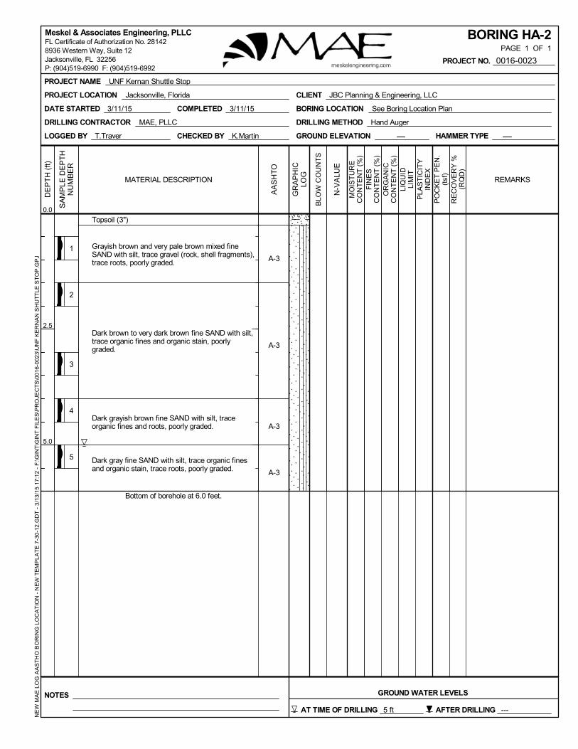
Generally, the auger borings encountered a surficial layer of topsoil about 3 inches thick underlain by fine sand with silt (A-3) to the borehole termination depth of 6 feet below existing grade. Many of the samples contained trace amounts of organic fines and roots and were organically stained. Trace amounts of gravel (shell and rock fragments) were encountered in the upper 1.5 to 2 feet below the topsoil layer.
4.2 Pavement Core Sample
The recovered core sample was returned to our laboratory to verify the asphalt thickness as measured in the field, and to observe its overall condition. The underlying base was not recoverable but was observed and measured in the field. Due to the thickness of the asphalt and limerock layers, the core barrel could not be extended into the underlying subgrade. The measured pavement layer thicknesses are shown in the table below:
Core No. Asphalt Thickness
(in.)
Pavement Base
Material Thickness (in.)
C-1 3 Limerock 11
Based on our observation of the asphalt core sample, the core consisted of two distinct layers of asphalt containing fine to coarse aggregate. The upper (surficial) layer measured one inch in thickness, underlain by a 2-inch layer. No change in mix was visually apparent. No cracks were

University of North Florida Kernan Shuttle Stop MAE Report No. 0016-0023
8936 Western Way, Suite 12 Jacksonville, Florida 32256
Phone: (904)519-6990 Fax: (904)519-6992
Page | 3
observed at top, bottom and sides of cores.
4.3 Groundwater Level
The hand auger borings encountered the groundwater level at a depth of about 5 feet below the existing ground surface at the time of drilling. However, it should be anticipated that the groundwater level will fluctuate seasonally and with changes in climate. As such, we recommend that the groundwater level be re-measured at the time of construction. Measured groundwater levels are shown on the Generalized Soil Profiles, Figure 3, and on the soil boring logs.
4.4 Seasonal High Groundwater Level
In estimating normal seasonal high groundwater level, a number of factors are taken into consideration including antecedent rainfall, soil redoximorphic features (i.e., soil mottling), stratigraphy (including presence of hydraulically restrictive layers), vegetative indicators, effects of development, and relief points such as drainage ditches, low-lying areas, etc.
Based on our interpretation of the current site conditions, including the boring logs, and review of published data, we estimate the seasonal high groundwater level at the site to be generally one to 2 feet above the groundwater levels measured at the time of our field work. It is our opinion that the water levels within the stormwater ponds adjacent to the northwest and southeast of the site significantly affect the groundwater level at the site.
It is possible that groundwater levels may exceed the estimated normal seasonal high groundwater level as a result of significant or prolonged rains. Therefore, we recommend that design drawings and specifications account for the possibility of groundwater level variations, and construction planning should be based on the assumption that such variations will occur.
5.0 DESIGN & CONSTRUCTION RECOMMENDATIONS
5.1 General
The following evaluation and recommendations are based on the provided project information as presented in this report and the results of the field exploration. If the described project conditions are incorrect or changed after this report, or if subsurface conditions encountered during construction are different from those reported, then MAE should be notified so that these recommendations can be re-evaluated and revised, if necessary. We recommend that MAE review the plans and specifications to verify that the recommendations in this report have been properly interpreted and implemented.
5.2 Shuttle Stop Slab & Sidewalk Considerations
Based on the results of our exploration, we consider the shallow subsurface conditions adaptable for support of the proposed Shuttle Stop and sidewalk concrete slab-on-grade structures, provided the site preparation and earthwork construction recommendations outlined in Section 6 below are performed.
5.2.1 Concrete Slab-on-Grade
The Shuttle Stop and sidewalk slabs can be constructed as a slab-on-ground, provided unsuitable material is removed, the stripped subgrade soils are uniformly compacted, and any required structural fill be compacted as outlined in Section 6.0. In addition, we recommend that a minimum

University of North Florida Kernan Shuttle Stop MAE Report No. 0016-0023
8936 Western Way, Suite 12 Jacksonville, Florida 32256
Phone: (904)519-6990 Fax: (904)519-6992
Page | 4
separation of 2 feet be maintained between the bottom of the slab and the seasonal high groundwater level.
5.3 Pavement Considerations
Based on the results of our exploration, we consider the subsurface conditions at the site favorable for support of a flexible pavement section, when constructed on properly prepared subgrade soils as outlined in Section 6 of this report.
5.3.1 Asphalt Wearing Surface
The wearing surface should consist of Florida Department of Transportation (FDOT) Type S-I or Type S-III asphaltic concrete having a minimum Marshall Stability of 1,500 lbs. Specific requirements for Type S asphaltic concrete wearing surface are outlined in the latest edition of the Florida Department of Transportation, Standard Specifications for Road and Bridge Construction.
5.3.2 Base and Subgrade
The limerock base course should have a minimum Limerock Bearing Ratio (LBR) of 100 and should be compacted to 100 percent of the modified Proctor maximum dry density (ASTM D 1557, AASHTO T-180) value.
The subgrade material should have a minimum LBR of 40 and be compacted to 98 percent of the modified Proctor maximum dry density (ASTM D 1557, AASHTO T-180) value.
6.0 SITE PREPARATION AND EARTHWORK RECOMMENDATIONS
Site preparation as outlined in this section should be performed to provide more uniform foundation bearing conditions, to reduce the potential for post-construction settlements of the planned structures and to maintain the integrity of a flexible pavement section.
6.1 Clearing and Stripping
The “footprint” of the proposed slab and sidewalk areas, plus a minimum margin of 3 feet, should be should be stripped of all surface vegetation, stumps, debris, organic topsoil, or other deleterious materials. During grubbing operations, roots with a diameter greater than 0.5-inch, stumps, or small roots in a concentrated state, should be grubbed and completely removed. Based on the results of our field exploration, it should be anticipated that about 3 inches of topsoil and soils containing significant amounts of organic materials will be encountered within the construction footprint.
6.2 Temporary Groundwater Control
The groundwater level was measured at a depth of 5 feet below existing grade at the time of our field exploration. Therefore, it is unlikely that temporary groundwater control measures to dewater the area to facilitate the compaction process will be necessary. However, if groundwater control measures become necessary, then the dewatering method should be determined by the contractor. We recommend that the groundwater control measures remain in place until compaction of the existing soils is completed. The dewatering method should be maintained until backfilling has reached a height of 2 feet above the groundwater level at the time of construction. The site should be graded to direct surface water runoff from the construction area.

University of North Florida Kernan Shuttle Stop MAE Report No. 0016-0023
8936 Western Way, Suite 12 Jacksonville, Florida 32256
Phone: (904)519-6990 Fax: (904)519-6992
Page | 5
6.3 Compaction
After completing the clearing and stripping operations and installing the temporary groundwater control measures (if required), the exposed surface area should be compacted with a vibratory drum roller having a minimum static, at-drum weight, on the order of five (5) tons. Typically, the material should exhibit moisture contents within ±2 percent of the modified Proctor optimum moisture content (ASTM D 1557) during the compaction operations. Compaction should continue until densities of at least 95 percent of the modified Proctor maximum dry density (ASTM D 1557) have been achieved within the upper one foot of the compacted natural soils at the site.
Should the bearing level soils experience pumping and soil strength loss during the compaction operations, compaction work should be immediately terminated. The disturbed soils should be removed and backfilled with dry structural fill soils, which are then compacted, or the excess moisture content within the disturbed soils should be allowed to dissipate before recompacting.
Care should be exercised to avoid damaging any nearby structures while the compaction operation is underway. Prior to commencing compaction, occupants of adjacent structures should be notified, and the existing conditions of the structures should be documented with photographs and survey (if deemed necessary). Compaction should cease if deemed detrimental to adjacent structures, and MAE should be contacted immediately. It is recommended that the vibratory roller remain a minimum of 50 feet from existing structures. Within this zone, use of a track-mounted bulldozer or a vibratory roller, operating in the static mode, is recommended.
6.4 Structural Backfill and Fill Soils
Any structural fill required for site development should be placed in loose lifts not exceeding 12 inches in thickness and compacted by the use of the above described vibratory drum roller. The lift thickness should be reduced to 8 inches if the roller operates in the static mode or if track-mounted compaction equipment is used. If hand-held compaction equipment is used, the lift thickness should be further reduced to 6 inches.
Structural fill is defined as a non-plastic, inorganic, granular soil having less than 10 percent material passing the No. 200 mesh sieve and containing less than 4 percent organic material. The fine sands with silt, without roots, as encountered in the borings are suitable as fill materials and, with proper moisture control, should densify using conventional compaction methods. It should be noted that soils with more than 10 to 12 percent passing the No. 200 sieve will be more difficult to compact, due to their nature to retain soil moisture, and may require drying. Typically, the material should exhibit moisture contents within ±2 percent of the modified Proctor optimum moisture content (ASTM D 1557) during the compaction operations. Compaction should continue until densities of at least 95 percent of the modified Proctor maximum dry density (ASTM D 1557) have been achieved within each lift of the compacted structural fill.
6.5 Pavement Area
After completing the clearing/stripping and surface compaction operations in the pavement area, structural backfill and fill required to achieve the finished pavement grades can then be placed and compacted as described in Section 6.3 above. As an exception, densities of at least 98 percent of the modified Proctor maximum dry density (AASHTO T180) should be obtained within the upper one foot of the materials immediately below the proposed base course.

University of North Florida Kernan Shuttle Stop MAE Report No. 0016-0023
8936 Western Way, Suite 12 Jacksonville, Florida 32256
Phone: (904)519-6990 Fax: (904)519-6992
Page | 6
7.0 REPORT LIMITATIONS
This report has been prepared for the exclusive use of JBC Planning & Engineering, Inc. for specific application to the design and construction of the planned Kernan Shuttle Stop facility. Our work for this project was performed in accordance with generally accepted geotechnical engineering practice. No warranty, express or implied, is made.
The evaluation and recommendations contained in this report are based on the data obtained from the hand auger borings and pavement core performed for this project. The pavement and subsurface conditions provided in this report are based only on those conditions encountered at the specific locations and times as reported, and only to the depths explored. These results do not reflect pavement and subsurface variations that may exist away from the core/boring locations, and/or variations in subsurface conditions at depths below the core/boring termination depths. Subsurface conditions and groundwater levels at other locations may differ from conditions encountered at the tested locations. In addition, it should be understood that the passage of time may result in a change in the subsurface conditions at the tested locations. If variations in pavement or subsurface conditions from those described in this report are observed during construction, the recommendations in this report must be re-evaluated.
The scope of our services did not include any environmental assessment or testing for the presence or absence of hazardous or toxic materials in the soil, groundwater, or surface water within or beyond the subject site. Any statements made in this report, and/or notations made on the generalized soil profiles or soil boring logs, regarding odors or other potential environmental concerns are based on observations made during execution of our scope of services and as such are strictly for the information of our client. No opinion of any environmental concern of such observations is made or implied. Unless complete environmental information regarding the site is already available, an environmental assessment is recommended.
If changes in the design or location of the project occur, the conclusions and recommendations contained in this report may need to be modified. We recommend that these changes be provided to us for our consideration. MAE is not responsible for conclusions, interpretations, opinions or recommendations made by others based on the data contained in this report.

Figures _____________________________________________________________________________________

Site Location Map
PREPARED BY PROJECT NAME
UNF Kernan Shuttle Stop Jacksonville, Florida
REFERERENCE SCALE
Delorme XMap 7.0 NTS PREPARED FOR MAE PROJECT NO. FIGURE NO.
JBC Planning & Engineering, LLC 0016-0023 1
Approximate Site
Location
N


0
0.5
1.0
1.5
2.0
2.5
3.0
3.5
4.0
4.5
5.0
5.5
6.0
6.5
0
0.5
1.0
1.5
2.0
2.5
3.0
3.5
4.0
4.5
5.0
5.5
6.0
6.5
JBC Planning & Engineering, LLC
MAE PROJECT NO.
(A-3) Depth to Groundwater at Time of Drilling
BY DESCRIPTION DATE BY DESCRIPTION
SHEET TITLE:
PROJECT NAME:
DATE
3/13/2015 0016-0023FIGURE NO.
Generalized Soil Profiles
3
Depth (ft)D
epth
(ft
)
Boring Terminated at Depth Below GradeBT
AASHTO Soil Classification System
DATE:
Legend
Topsoil Fine Sand with Silt
UNF Kernan Shuttle StopJacksonville, FloridaFL Certificate of Authorization No. 28142
8936 Western Way, Suite 12, Jacksonville, FL 32256
BT @ 6.0'.Date Drilled: 3/11/2015
Topsoil (3")
Dark brown to very dark brown fineSAND with silt, trace organic fines andorganic stain, poorly graded. (A-3)
Dark gray fine SAND with silt, traceorganic fines and organic stain, traceroots, poorly graded. (A-3)
BT @ 6.0'.Date Drilled: 3/11/2015
Topsoil (3")
Grayish brown and very pale brownmixed fine SAND with silt, trace gravel(rock, shell fragments), trace roots,poorly graded. (A-3)
Dark brown to very dark brown fineSAND with silt, trace organic fines andorganic stain, poorly graded. (A-3)
Grayish brown and very pale brownmixed fine SAND with silt, trace gravel(rock, shell fragments), trace roots,poorly graded. (A-3)
Dark grayish brown fine SAND with silt,trace organic fines and roots, poorlygraded. (A-3)
Dark grayish brown fine SAND with silt,trace organic fines and roots, poorlygraded. (A-3)
Dark gray fine SAND with silt, traceorganic fines and organic stain, traceroots, poorly graded. (A-3)
HA-1 HA-2
P. RODNEY MANK, P.E. P.E. NO.: 41986
Meskel & Associates Engineering, PLLC

Appendix A _____________________________________________________________________________________

1
2
3
4
Topsoil (3")
Grayish brown and very pale brown mixed fineSAND with silt, trace gravel (rock, shell fragments),trace roots, poorly graded.
Dark brown to very dark brown fine SAND with silt,trace organic fines and organic stain, poorlygraded.
Dark grayish brown fine SAND with silt, traceorganic fines and roots, poorly graded.
Dark gray fine SAND with silt, trace organic finesand organic stain, trace roots, poorly graded.
Bottom of borehole at 6.0 feet.
A-3
A-3
A-3
A-3
COMPLETED 3/11/15DATE STARTED 3/11/15
DRILLING CONTRACTOR MAE, PLLC
LOGGED BY T.Traver CHECKED BY K.Martin GROUND ELEVATION HAMMER TYPE
DRILLING METHOD Hand Auger
BORING LOCATION See Boring Location Plan
MO
IST
UR
EC
ON
TE
NT
(%
)
PLA
ST
ICIT
YIN
DE
X
GR
AP
HIC
LOG
N-V
ALU
E
BLO
W C
OU
NT
S
REMARKS
SA
MP
LE D
EP
TH
NU
MB
ER
PO
CK
ET
PE
N.
(tsf
)R
EC
OV
ER
Y %
(RQ
D)
FIN
ES
CO
NT
EN
T (
%)
LIQ
UID
LIM
IT
MATERIAL DESCRIPTION
DE
PT
H (
ft)
0.0
2.5
5.0
OR
GA
NIC
CO
NT
EN
T (
%)
AA
SH
TO
BORING HA-1PAGE 1 OF 1
GROUND WATER LEVELSNOTES
AFTER DRILLING ---
PROJECT NAME UNF Kernan Shuttle Stop
PROJECT LOCATION Jacksonville, Florida CLIENT JBC Planning & Engineering, LLC
PROJECT NO. 0016-0023
NE
W M
AE
LO
G A
AS
TH
O B
OR
ING
LO
CA
TIO
N -
NE
W T
EM
PLA
TE
7-3
0-12
.GD
T -
3/1
3/15
17
:12
- F
:\GIN
T\G
INT
FIL
ES
\PR
OJE
CT
S\0
016
-002
3\U
NF
KE
RN
AN
SH
UT
TLE
ST
OP
.GP
JMeskel & Associates Engineering, PLLCFL Certificate of Authorization No. 281428936 Western Way, Suite 12Jacksonville, FL 32256P: (904)519-6990 F: (904)519-6992
AT TIME OF DRILLING 5 ft
1
2
3
4
5
Topsoil (3")
Grayish brown and very pale brown mixed fineSAND with silt, trace gravel (rock, shell fragments),trace roots, poorly graded.
Dark brown to very dark brown fine SAND with silt,trace organic fines and organic stain, poorlygraded.
Dark grayish brown fine SAND with silt, traceorganic fines and roots, poorly graded.
Dark gray fine SAND with silt, trace organic finesand organic stain, trace roots, poorly graded.
Bottom of borehole at 6.0 feet.
A-3
A-3
A-3
A-3
COMPLETED 3/11/15DATE STARTED 3/11/15
DRILLING CONTRACTOR MAE, PLLC
LOGGED BY T.Traver CHECKED BY K.Martin GROUND ELEVATION HAMMER TYPE
DRILLING METHOD Hand Auger
BORING LOCATION See Boring Location Plan
MO
IST
UR
EC
ON
TE
NT
(%
)
PLA
ST
ICIT
YIN
DE
X
GR
AP
HIC
LOG
N-V
ALU
E
BLO
W C
OU
NT
S
REMARKS
SA
MP
LE D
EP
TH
NU
MB
ER
PO
CK
ET
PE
N.
(tsf
)R
EC
OV
ER
Y %
(RQ
D)
FIN
ES
CO
NT
EN
T (
%)
LIQ
UID
LIM
IT
MATERIAL DESCRIPTION
DE
PT
H (
ft)
0.0
2.5
5.0
OR
GA
NIC
CO
NT
EN
T (
%)
AA
SH
TO
BORING HA-2PAGE 1 OF 1
GROUND WATER LEVELSNOTES
AFTER DRILLING ---
PROJECT NAME UNF Kernan Shuttle Stop
PROJECT LOCATION Jacksonville, Florida CLIENT JBC Planning & Engineering, LLC
PROJECT NO. 0016-0023
NE
W M
AE
LO
G A
AS
TH
O B
OR
ING
LO
CA
TIO
N -
NE
W T
EM
PLA
TE
7-3
0-12
.GD
T -
3/1
3/15
17
:12
- F
:\GIN
T\G
INT
FIL
ES
\PR
OJE
CT
S\0
016
-002
3\U
NF
KE
RN
AN
SH
UT
TLE
ST
OP
.GP
JMeskel & Associates Engineering, PLLCFL Certificate of Authorization No. 281428936 Western Way, Suite 12Jacksonville, FL 32256P: (904)519-6990 F: (904)519-6992
AT TIME OF DRILLING 5 ft

FIELD EXPLORATION PROCEDURES
Hand Auger Boring
The auger boring(s) were performed manually by the use of a hand auger and in general
accordance with the latest revision of ASTM D 1452, “Soil Investigation and Sampling by
Auger Borings.” Representative samples of the soils brought to the ground surface by the
augering process were placed in sealed containers and transported to our laboratory
where they were examined by our engineer to verify the driller’s field classification.

S o i l C l
SoilclassiHighwaya50% of thboulders.principallymaybeadongrainsdensityan
SymbN
WORWOH50/2
(A‐3)‐200wOCLLPINPPP
S
San
VerySandy
Highly
(
K
l a s s i f i c a t
ficationofsamandTransportheir dry weig Fine grainedydescribedasddedasmodifiize.Inadditiondfine‐grained
bol DeStasam
R SplH Spl” Ind
inc
) AA0 Fin
NaOrgLiqPlaNoPo
MO
SECONDARY(Sand,
TraceWith
ndy,SiltyorClay
y,VerySiltyorV
ORGANTraceFew
OrganicSoilyOrganicSoil(M
PEAT
MINORCShell,Rock,D
Trace
Few
Little
Some
KEY TO
t i o n
mplesobtainetationOfficialght retainedd soils have lesclaysiftheyiersandminoontogradatiodsoilsonthe
escriptionandardPenetrampler12"when
litSpoonsampllitSpoonsampldicates50hammchesofsplitspo
ASHTOSoilClasnescontent,%PaturalMoistureganicContent(quidLimitasticityIndexon‐PlasticcketPenetrome
DIFIERS
YCONSTITUSiltorClay)
yey
VeryClayey
ICCONTENT
Muck)G
COMPONENTDebris,Roots
BORIN
edattheborils(AASHTO)Con a #200 siess than 50%areplasticanorconstituentson,coarse‐grabasisoftheir
BORIN
tionResistancendrivenbya14
leradvancedunleradvancedunmerblowsdrovoondrivingisco
sificationSystePassingNo.200Content(%)(%)
eterintonsper
ENTS
Lessthan5%5%to12%12%to35%
35%to50%
T
2%orless3%to5%5%to20%20%to75%
Greaterthan75
TSs,etc.)Lessthan5%
5%to10%
15%to25%
30%to45%
NG LOG
nglocationsiClassificationieve. Their p% of their dryndsiltsiftheysmaybeaddeainedsoilsareconsistency.
GLOGLEGE
e,thenumberof40‐lbhammerd
ndertheweightndertheweightvethesplitspooonsidered“Refu
m0U.S.Standard
rsquarefoot(ts
RELAR
%
5%
% R
GS – AA
isbasedonthSystem.Coarprincipal desyweight retaiareslightlytoedaccordingtedefinedonth
END
fblowsrequiredropping30".
tofthedrillrodtoftheSPThamon2inches;50usal”.
Sieve
sf)
ATIVEDENSRelativeDen
VeryLooseLoose
MediumDensDense
VeryDense
CONSISTENConsistencVerySoftSoftFirmStiff
VeryStiff
Hard
RELATIVEHRelativeHard
SoftHard
SHTO
heAmericanArsegrainedsocriptors are:ned on a #20onon‐plastic.totherelativehebasisofthe
edtoadvancea
dsmmerHammerblows
SITY(Coarssity
se
e
NCY(Fine‐Grcy
HARDNESS(dness
Associationofoilshavemoresand, cobble00 sieve. TheMajorconstiteproportionseirin‐placere
standardspoon
sforlessthan6
e‐GrainedSN‐ValueLessthan44to10
10to3030to50
Greaterthan
rainedSoils)N‐ValueLessthan22to44to88to1515to30
Greaterthan
(Limestone)N‐ValueLessthan5
Greaterthan
fStateethanes andey aretuentsbasedelative
n
6‐
Soils)
4
50
)
2
30
)
050

* Plasticity index of A-7-5 subgroup is equal to or less than the LL - 30. Plasticity index of A-7-6 subgroup is greater than LL – 30
** Northeast Florida
AASHTO Soil Classification System (from AASHTO M 145 or ASTM D 3282)
General Classification Granular Materials
(35% or less passing the 0.075 mm sieve) Silt-Clay Materials
(>35% passing the 0.075 mm sieve)
Group Classification
A-1
A-3
A-2
A-4 A-5 A-6
A-7
A-1-a A-1-b A-2-4 A-2-5 A-2-6 A-2-7 A-7-5* A-7-6*
Sieve Analysis, % passing:
2.00 mm (No. 10) 50 max … … … … … … … … … …
0.425 (No. 40) 30 max 50 max 51 min … … … … … … … …
0.075 (No. 200) 15 max 25 max 10 max 35 max 35 max 35
max 35 max 36 min 36 min 36 min 36 min
Characteristics of fraction passing 0.425 mm (No. 40):
Liquid Limit … … 40 max 41 min 40
max 41 min 40 max 41 min 40 max 41 min
Plasticity Index 6 max N.P. 10 max 10 max 11 min 11 min 10 max 10 max 11 min 11 min
Usual types of significant constituent materials
stone fragments,
gravel and sand
fine sand
silty or clayey gravel and sand silty soils clayey soils
General local** rating as a subgrade
excellent to good fair to poor

Appendix B _____________________________________________________________________________________