macnaught positive displacement flowmeters · macnaught positive displacement flowmeters....
52
macnaught positive displacement flowmeters
Transcript of macnaught positive displacement flowmeters · macnaught positive displacement flowmeters....

macnaughtpositive displacement flowmeters

macnaught.com.au
Macnaught Pty Ltd was
established in 1948 and is an
independent 100% Australian-
owned manufacturing company
based at Turrella in Sydney,
Australia.
Macnaught’s M-SERIES™
is a comprehensive range of
quality positive displacement
flowmeters, designed and
manufactured in our factory.
Macnaught has added a new
range of meters to the existing
range designated
WM-SERIES™. This range of
meters have the same
specifications as the
M-SERIES™, with exception
that these meters have Weights
and Measures certification.
By closely monitoring the needs
and knowledge of its
international user base,
Macnaught strives to continually
improve its products and
customer service levels to set
new standards.
With strong market leadership
in Australia, Macnaught
products are sold successfully
through a distributor network in
more than 60 countries.
Highlighting the importance
placed on export successes
and to service the growing
needs in multiple regions,
Macnaught has sales offices in
Singapore, Indonesia, the USA
and the UK.
In recognition of the company’s
achievements, Macnaught has
won three Australian National
Export Awards and two
Australian Design Council
Awards.
3
Contents
Product Numbering System 6
M05 – 1/8” Flowmeters 8
M1 – 1/4” Flowmeters 10
M2 – 1/4” Flowmeters 12
M4 – 1/2” Flowmeters 14
M6 – 3/4” Flowmeters 18
M7 – 1” Flowmeters 20
M10 – 1” Flowmeters 22
M40 – 11⁄2” Flowmeters 26
M50 – 2” Flowmeters 30
M80 – 3” Flowmeters 34
M100 – 4” Flowmeters 38
Options & Accesories 42
Register Information 43
Certifications 45
Applications & Fluid Viscosities 46
Performance Data 47
After Sales Service & Warranties 50

4
Certificates and Accreditation
Quality Endorsementapplicable to MacnaughtHead Office Sydney Only
Standards Australia National Association of Testing Authorities
Macnaught Pty LtdAccreditation No: 15485
A test facility that complies withthe requirements of ISO/IEC 17025 (2005)
• Flow Measuring devices -Liquid Meters
• Calibration of flow rate and volume on oil 0.25 l/m to 750 l/m
Contact Macnaught for more information
National Conference on Weights and Measurement
Certificate Number: 07-061
• National Type Evaluation Program
• Certificate of Conformation for Weighing and
Measuring Devices
• Meter Indicating Volume (Stationary Application)
• Pulse Output Meters Only
• Meter Types: M10, M40, M50, M80
Contact Macnaught for more information
Australian Government NationalMeasurement Institute
Interim Certificate of Approval No 5/6B/211
• Meter Indicating Volume (Stationary Application)
• Pulse Output Meters Only
• Meter Types: WM10, WM40, WM50, WM80
and WM100
Contact Macnaught for more information

5
6
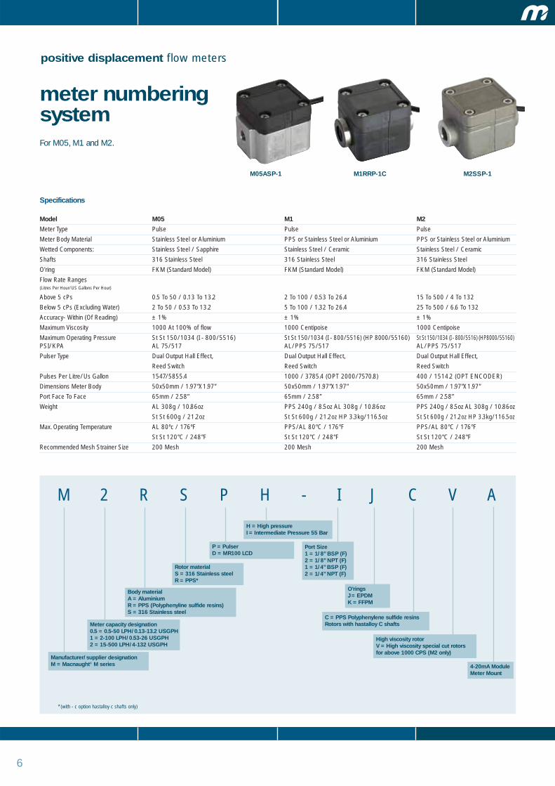
positive displacement flow meters
Specifications
Model M05 M1 M2
Meter Type Pulse Pulse Pulse
Meter Body Material Stainless Steel or Aluminium PPS or Stainless Steel or Aluminium PPS or Stainless Steel or Aluminium
Wetted Components: Stainless Steel / Sapphire Stainless Steel / Ceramic Stainless Steel / Ceramic
Shafts 316 Stainless Steel 316 Stainless Steel 316 Stainless Steel
O'ring FKM (Standard Model) FKM (Standard Model) FKM (Standard Model)
Flow Rate Ranges (Litres Per Hour/US Gallons Per Hour)
Above 5 cPs 0.5 To 50 / 0.13 To 13.2 2 To 100 / 0.53 To 26.4 15 To 500 / 4 To 132
Below 5 cPs (Excluding Water) 2 To 50 / 0.53 To 13.2 5 To 100 / 1.32 To 26.4 25 To 500 / 6.6 To 132
Accuracy- Within (Of Reading) ± 1% ± 1% ± 1%
Maximum Viscosity 1000 At 100% of flow 1000 Centipoise 1000 Centipoise
Maximum Operating Pressure St St 150/1034 (I - 800/5516) St St 150/1034 (I - 800/5516) (HP 8000/55160) St St 150/1034 (I - 800/5516) (HP8000/55160)PSI/KPA AL 75/517 AL/PPS 75/517 AL/PPS 75/517
Pulser Type Dual Output Hall Effect, Dual Output Hall Effect, Dual Output Hall Effect,
Reed Switch Reed Switch Reed Switch
Pulses Per Litre/Us Gallon 1547/5855.4 1000 / 3785.4 (OPT 2000/7570.8) 400 / 1514.2 (OPT ENCODER)
Dimensions Meter Body 50x50mm / 1.97”X1.97” 50x50mm / 1.97”X1.97” 50x50mm / 1.97”X1.97”
Port Face To Face 65mm / 2.58” 65mm / 2.58” 65mm / 2.58”
Weight AL 308g / 10.86oz PPS 240g / 8.5oz AL 308g / 10.86oz PPS 240g / 8.5oz AL 308g / 10.86oz
St St 600g / 21.2oz St St 600g / 21.2oz HP 3.3kg/116.5oz St St 600g / 21.2oz HP 3.3kg/116.5oz
Max. Operating Temperature AL 80ºc / 176ºF PPS/AL 80°C / 176°F PPS/AL 80°C / 176°F
St St 120°C / 248°F St St 120°C / 248°F St St 120°C / 248°F
Recommended Mesh Strainer Size 200 Mesh 200 Mesh 200 Mesh
M 2 R S P H - I J C V A
M1RRP-1C M2SSP-1
Port Size1 = 1/8” BSP (F)2 = 1/8” NPT (F)1 = 1/4” BSP (F)2 = 1/4” NPT (F)
O’ringsJ = EPDMK = FFPM
meter numberingsystemFor M05, M1 and M2.
* (with - c option hastalloy c shafts only)
M05ASP-1
C = PPS Polyphenylene sulfide resinsRotors with hastalloy C shafts
Manufacturer/supplier designationM = Macnaught® M series
Meter capacity designation0.5 = 0.5-50 LPH/0.13-13.2 USGPH1 = 2-100 LPH/0.53-26 USGPH2 = 15-500 LPH/4-132 USGPH
Body materialA = AluminiumR = PPS (Polyphenyline sulfide resins)S = 316 Stainless steel
Rotor materialS = 316 Stainless steelR = PPS*
P = PulserD = MR100 LCD
H = High pressureI = Intermediate Pressure 55 Bar
High viscosity rotorV = High viscosity special cut rotors for above 1000 CPS (M2 only)
4-20mA ModuleMeter Mount

7
A = Analogue registerI = Industrial registerVR = Veeder-Root Registers
positive displacement flow meters
Model M4 M6 M7 M10 M40 M50 M80 M100Meter Type Pulse (Refer to meter numbering system for LCD or mechanical options) WM10 WM40 WM50 WM80 WM100
Meter Body Material Aluminium, Stainless Steel, Bronze, PPS
Wetted Components:
Rotor Material PPS or Stainless Steel PPS / Stainless Steel PPS or Stainless Steel PPS or Stainless Steel PPS or Stainless Steel PPS or Stainless Steel Aluminium / Stainless Steel Aluminium / Stainless Steel
Shafts Stainless Steel Stainless Steel Stainless Steel or Hastalloy Stainless Steel Stainless Steel Stainless Steel STST / Hardened steel STST / Hardened steel
O'ring NBR Standard NBR Standard NBR Standard NBR Standard NBR Standard NBR Standard NBR Standard NBR Standard
(For options refer numbering system)
Flow Rate Ranges (Litres Per Minute/US Gallons Per Minute)
Above 5 cPs 2 To 30 / 0.5 To 8 3 To 80 / 0.8 To 21 3 To 80 / 0.8 To 21 6 To 120 / 1.6 To 32 15 - 350 14 - 93 20 To 750 / 5 To 194 120 To 1200 / 32 To 317
Below 5 cPs 3 To 25 / 0.8 To 6.6 8 To 70 / 2 To 18.5 8 To 70 / 2 To 18.5 10 To 100 / 2.6 To 26 HF 15 - 550 HF 4 - 146 66 To 616 / 17 To 163 220 To 1000 / 58 To 264
Accuracy - Within ± 0.5% ± 0.5% ± 0.5% ± 0.5% ± 0.5% ± 0.5% ± 0.5% ± 0.5%
(Of Reading) Note: Mechanical option is digital ± 1% analogue ± 0.5%
Maximum Viscosity 1000 cPs ( > 1,000,000 With HV Rotors)
(Of Standard Model)
Maximum Operating Pressure See Relevant Individual Model Specifications
Pulser Type Dual Reed Switch (For options refer to numbering system)
Pulses Per Litre/Us Gallon 112 / 424 52 / 196.8 52 / 196.8 36 / 136.3 14.5 / 54.9 6.68 / 25.29 2.59 / 9.81 2.315 / 8.763
Max. Operating 80°C / 176°F (For High Temperature Rotors Refer
Temperature To Meter Numbering System) St St Rotors 120º/248ºF
Strainer Size Recded Mesh 60 Mesh 60 Mesh 60 Mesh 60 Mesh 60 Mesh 40 Mesh 40 Mesh 40 Mesh
M 4 R R P A - I E H T V S L A
Display/PulserP = Pulser onlyE = Deluxe LC Display and PulserG = Standard LC Display and PulserD = MR100 LCDM = Mechanical registers
Rotor materialA = AluminiumR = PPS (Polyphenylene Sulfide Resins)S = 316 Stainless SteelN = PPS High Flow (M50 Only)
Body materialA = AA610 AluminiumS = 316 Stainless SteelB = BronzeR = PPS (Polyphenylene Sulfide Resins)
Meter size and capacity4 = 1/2” 2-30LPM/0.5-8 US GPM6 = 3/4” 3-80 LPM / 0.8-21 US GPM7 = 1” 3-80 LPM/0.8-21 US GPM10 = 1” 6-120 LPM/1.6-32 US GPM40 = 1 1/2” 10-250 LPM/4-93 US GPM50 = 2” 15-350 LPM/4-93 US GPM50 = 2” 15-550 LPM/4-145 US GPM80 = 3” 20-733 LPM/5-194 US GPM100 = 4” 120-1200 LPM/52-317 US GPM
Port size1 = BSP(F) - Litre, 2 = NPT(F) US Gallons3 = ANSI 150lb Flange - Litre, 4 = ANSI 150lb flange - USG5 = DIN Flange version, 6 = Tri-clover - Litre and SS only7 = Tri-clover - USG, 13 = JIS 10K Flange
Manufacturer supplier designationM = Macnaught® M-SERIES™WM = Macnaught WM-SERIES™ (Weights & Measures approved models)
M4 M7 M10 M40 M50 M80 M100
Macnaught Pty Ltd reserves the right to modify or alter product materials, dimensions, design and construction, when necessary, to improve the performance of our products. Please check with your local distributor or Macnaught to confirm current specifications of our products.
Hall effect sensor in place of standard reed switch(3 wire 4.5 - 24vDC) ER - Hall / Reed Combination
High viscosity rotorsH = High viscosity special cutRotors for above 1000cps
NPT - PORTLitre calibration
Solvent kit - mechanical version only Included in St St Models
O’ringsJ = EPDM, K = FEP encapsulated, V = FKM
High Tempreature PPS Rotors (120ºC/248ºF)
meter numbering systemFor M4, M6, M7, M10, WM10, M40, WM40, M50, WM50, M80, WM80, M100 and WM100.
M6
4-20mA ModuleMeter Mount

8
positive displacement flow meters
M05 – 1/8” pulse metersThe M05 is a small capacity meter in the M-SERIES™ range and isdifferentiated by its flow rate capabilities. It has the ability to handle awide range of fluid viscosities with exceptional levels of repeatabilityand durability.
Features
• Very compact size.
• Low flow capability with high resolution output.
• Meter accuracy is verified by a factory calibration check after which an individual metrology report is issued.
• Solid state Hall Effect Sensor/Reed Combination.
• Low pressure drop allows for economical pump selection or gravity flow applications.
• Meter design minimises the number of wearable and replaceable parts and extends product life.
• Has IP54/NEMA13 protection.
• Flexibility of installation options (e.g. can be mounted horizontally or vertically; no flowconditioning required).
Specification:
MODEL M05SSP-X M05ASP-XMeter Type Pulse Pulse
Meter Body Material 316 Stainless Steel Aluminium / PPS
Wetted Components:
Rotor Material 316 Stainless Steel / Ceramic 316 Stainless Steel / Bronze
Shafts 316 Stainless Steel 316 Stainless Steel
O'ring FKM FKM
Flow Rate Ranges (Litres Per Hour/US Gallons Per Hour)
Above 5 cPs 0.5 To 50 / 0.13 To 13.2 0.5 To 50 / 0.13 To 13.2
Below 5 cPs 2 To 50 / 0.53 To 13.2 (Excluding Water) 2 To 50 / 0.53 To 13.2
Accuracy- Within +/- 1% +/- 1%
(Of Reading)
Repeatability 0.03% 0.03%
Maximum Viscosity 1000 Centipoise 1000 Centipoise
Maximum Operating Pressure 1000kpa/ 150psi/ 10bar “I” 5500kpa/ 800psi/ 55bar 500kpa/ 75psi/ 5bar
Pulser Type Dual Hall Effect Sensor/ Dual Hall Effect Sensor/
Reed Switch Reed Switch
Pulses Per Litre/US Gallon 1547 / 5855.4 1547 / 5855.4
Model Dimensions
Meter Body 50x50mm / 1.97”X1.97” 50mm X 50mm/1.97” X 1.97”
Port Face To Face 67mm / 2.64” 60mm / 2.36”
Weight 600g / 21.2oz 310g / 11oz
Max. Operating Temperature 120°C / 248°F 80°C / 176°F
Recommended Mesh 200 Mesh 200 Mesh
Strainer
X = Port Size To order flowmeter you must replace ‘X’ with the relevant number. Meter mounted options = MR100 LCD and or MR150LA (4-20mA - module) or combination of both.
Port Size:
Port Size: Calibrated In: Electrical Connections
1 = 1/8” BSP (F) ports litres 1m/39” pulser fly lead (5 core cable)
2 = 1/8” NPT (F) ports US gallons 1m/39” pulser fly lead (5 core cable)
PPS = Polyphenylene Sulfide ResinsNote: Water usage is limited due to poor lubricating quality of the fluid limiting accuracy and bottom end stable operation.
M05ASP-X
MR100

9
M05 – 1/8” pulse metersOptions and accessories
M05 - 1/8” Pulse Meters M05SSP-X M05ASP-X
FKM O-Ring � �
FFPM Elastomer � �
EPDM O-Ring � �
High Temp Rotors – –
High Viscosity Rotors – –
Hall Effect Sensor � �
Reed Switch � �
Solvent Kit – –
PPS Rotors With Hastalloy C Shafts – –
Remote Mounted LC Display + +
4-20ma Module (Remote) + +
Meter Mounted LC Display + +
Meter Mounted 4-20mA Module + +
� Standard � Optional – Not Available + Accessory
Macnaught Pty Ltd reserves the right to modify or alter product materials, dimensions, design and construction, when necessary, to improve the performance of our products. Please check with your local distributor or Macnaught to confirm current specifications of our products.
Dimensions
Standard meter
50mm
36.5mm
50mm
80mm 67mm
(60mm AL)
18m
m
18m
m
25m
m ø
36.5
mm
36.5mm
36.5
mm
25m
m
76m
m
50m
m
70m
m
Standard meter with MR100
Generic Diagram for M05/M1/M2 (fitted with MR100 Register)
Note: When MR150 is fitted the O/A height increases by 22mm for each model.(Sizes are common,) as shown in plan view.

10
positive displacement flow meters
M1 – 1/4” pulse metersThe M1 is a small capacity meter in the M-SERIES™ range and isdifferentiated by its flow rate capabilities. It has the ability to handle awide range of fluid viscosities with exceptional levels of repeatabilityand durability.
Features
• Very compact size.
• Low flow capability with high resolution output.
• Meter accuracy is verified by a factory calibration check after which an individual metrology report is issued.
• Solid state Hall Effect Sensor/Reed Combination.
• Low pressure drop allows for economical pump selection or gravity flow applications.
• Meter design minimises the number of wearable and replaceable parts and extendsproduct life.
• Has IP54/NEMA13 protection.
MISSPH-XY IP65-NEMA 9
• Flexibility of installation options (e.g. can be mounted horizontally or vertically; no flowconditioning required).
Specification:
MODEL M1RSP-X M1SSP-X M1SSPH-X M1ASP-XMeter Type Pulse Pulse Pulse Pulse
Meter Body Material PPS 316 Stainless Steel 316 Stainless Steel Aluminium / PPS
Wetted Components:
Rotor Material 316 Stainless Steel / Ceramic 316 Stainless Steel / Ceramic 316 Stainless Steel / Ceramic 316 Stainless Steel / Bronze
Shafts 316 Stainless Steel 316 Stainless Steel 316 Stainless Steel 316 Stainless Steel
O'ring FKM FKM FKM FKM
Flow Rate Ranges (Litres Per Hour/US Gallons Per Hour)
Above 5 cPs 2 To 100 / 0.53 To 26.4 2 To 100 / 0.53 To 26.4 2 To 100 / 0.53 To 26.4 2 To 100 / 0.53 To 26.4
Below 5 cPs (Excluding Water) 5 To 100 / 1.32 To 26.4 5 To 100 / 1.32 To 26.4 5 To 100 / 1.32 To 26.4 5 To 100 / 1.32 To 26.4
Accuracy- Within +/- 1% +/- 1% +/- 1% +/- 1%
(Of Reading)
Repeatability 0.03% 0.03% 0.03% 0.03%
Maximum Viscosity 1000 Centipoise 1000 Centipoise 1000 Centipoise 1000 Centipoise
Maximum Operating Pressure 500kpa/ 75 Psi/ 5 Bar 1000kpa/ 150psi/ 10bar 55160kpa/ 8000psi/ 551bar 500kpa/ 75psi/ 5bar
Pulser Type Dual Hall Effect Sensor/ Dual Hall Effect Sensor/ Hall Effect Sensor Dual Hall Effect Sensor/
Reed Switch Reed Switch or Reed Switch Reed Switch
Pulses Per Litre/US Gallon 1000 / 3785.4 1000 / 3785.4 1000 / 3785.4 1000 / 3785.4
Model Dimensions
Meter Body 50x50mm / 1.97”X1.97” 50x50mm / 1.97”X1.97” 86mm Dia X 110mm H/3.4” Dia X 4.33” H 50mm X 50mm/1.97” X 1.97”
Port Face To Face 67mm / 2.64” 67mm / 2.64” 83mm / 3.26” 60mm / 2.36”
Weight 240g / 8.5oz 600g / 21.2oz 3.3kg / 116.5oz 310g / 11oz
Max. Operating Temperature 80°C / 176°F 120°C / 248°F 120°C / 248°F 80°C / 176°F
Recommended Mesh 200 Mesh 200 Mesh 200 Mesh 200 Mesh
Strainer
X = Port Size To order flowmeter you must replace ‘X’ with the relevant number. Meter mounted options = MR100 LCD and or MR150LA (4-20mA - module) or combination of both.
Port Size:
Port Size: Calibrated In: Electrical Connections
1 = 1/4” BSP (F) ports litres 1m/39” pulser fly lead (5 core cable)
2 = 1/4” NPT (F) ports US gallons 1m/39” pulser fly lead (5 core cable)
1 = 1/4” BSP (F) ports HP only with litres 20mm (F) Conduit Thread
2 = 1/4” NPT (F) ports pulser cap US gallons 1/2” NPT (F)
PPS = Polyphenylene Sulfide ResinsNote: Water usage is limited due to poor lubricating quality of the fluid limiting accuracy and bottom end stable operation.
]
M1SSPH-X
M1RSP-X MR100
11
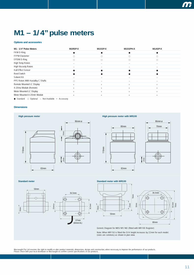
M1 – 1/4” pulse metersOptions and accessories
M1 - 1/4” Pulse Meters M1RSP-X M1SSP-X M1SSPH-X M1ASP-X
FKM O-Ring � � � �
FFPM Elastomer � � � �
EPDM O-Ring � � � �
High Temp Rotors – – – –
High Viscosity Rotors – – – –
Hall Effect Sensor � � � �
Reed Switch � � � �
Solvent Kit – – – –
PPS Rotors With Hastalloy C Shafts � – – –
Remote Mounted LC Display + + + +
4-20ma Module (Remote) + + + +
Meter Mounted LC Display + + + +
Meter Mounted 4-20mA Module + + + +
� Standard � Optional – Not Available + Accessory
Macnaught Pty Ltd reserves the right to modify or alter product materials, dimensions, design and construction, when necessary, to improve the performance of our products. Please check with your local distributor or Macnaught to confirm current specifications of our products.
Dimensions
High pressure meter
Standard meter
83mm
86mm ø
110m
m
23m
m19
mm
83mm
86mm ø
80mm 70mm
110m
m
23m
m
50mm
36.5mm
50mm
80mm 67mm
(60mm AL)
18m
m
18m
m
25m
m ø
36.5
mm
36.5mm
36.5
mm
25m
m
76m
m
50m
m
70m
m
High pressure meter with MR100
Standard meter with MR100
Generic Diagram for M05/M1/M2 (fitted with MR100 Register)
Note: When MR150 is fitted the O/A height increases by 22mm for each model.(sizes are common,) as shown in plan view.

12
positive displacement flow meters
M2 – 1/4” pulse metersThe M2 is one of the small capacity meters in the M-SERIES™ rangeand is differentiated by its flow rate capabilities. It has the ability tohandle a wide range of fluid viscosities with exceptional levels ofrepeatability and durability.
Features:
• Very compact size.
• Low flow capability with high resolution output.
• Solid state Hall Effect Sensor/Reed Switch Combination.
• Has IP54/NEMA13 protection. (M2SSPH-XY IP65/NEMA9)
• Flexibility of installation options (e.g. can be mounted horizontally or vertically; no flowconditioning required).
• Meter accuracy is verified by a factory calibration check after which an individualmetrology report is issued.
• Low pressure drop allows for economical pump selection or gravity flow applications.
• Meter design minimises the number of wearable and replaceable parts and extendsproduct life.
Specifications:
MODEL M2RSP-X M2SSP-X M2SSPH-X M2ASP-XMeter Type Pulse Pulse Pulse Pulse
Meter Body Material PPS 316 Stainless Steel 316 Stainless Steel Aluminium
Wetted Components:
Rotor Materials 316 Stainless Steel / Ceramic 316 Stainless Steel / Ceramic 316 Stainless Steel / Ceramic 316 Stainless Steel / Ceramic
Shafts 316 Stainless Steel 316 Stainless Steel 316 Stainless Steel 316 Stainless Steel
O'ring FKM FKM FKM FKM
Flow Rate Ranges (Litres Per Hour/US Gallons Per Hour)
Above 5 cPs 15 To 500 / 4 To 132 15 To 500 / 4 To 132 15 To 500 / 4 To 132 15 To 500 / 4 To 132
Below 5 cPs 25 To 500 / 7 To 132 (Excluding Water) 25 To 500 / 7 To 132 25 To 500 / 7 To 132 25 To 500 / 7 To 132
Accuracy- Within (of reading) +/- 1% +/- 1% +/- 1% +/- 1%
Repeatability 0.03% 0.03% 0.03% 0.03%
Maximum Viscosity 1000 Centipoise ( > 1000 Option) 1000 Centipoise ( > 1000 Option) 1000 Centipoise ( > 1000 Option) 1000 Centipoise ( > 1000 Option)
Maximum Operating
Pressure 500kpa/ 75 Psi/ 5 Bar 1000kpa/ 150psi/ 10bar 55000kpa/8000psi/550Bar 500kpa/ 75psi/ 5bar(Intermediate 5500kpa/800psi/ 55Bar)
Pulser Type Dual Hall Effect Sensor/Reed Switch Dual Hall Effect Sensor/Reed Switch Hall Effect Sensor or Reed Switch Dual Hall Effect Sensor/Reed Switch
Pulses Per Litre/Us Gallon 400 / 1514.2 400 / 1514.2 400 / 1514.2 400 / 1514.2
Model Dimensions
Meter Body 50x50mm / 1.97”X1.97” 50x50mm / 1.97”X1.79” 86mm Dia X 110mm H / 3.4” Dia X 4.33” H 50mm X 50mm / 1.97” X 1.97”
Port Face To Face 67mm / 2.64” 67mm / 2.64” 83mm / 3.26” 60mm / 2.36”
Weight 240g / 8.5oz 600g / 21.2oz 3.3kg /116.5oz 320g /12g
Max. Operating
Temperature 80°C / 176°F 120°C / 248°F 120°C / 248°F 80°C / 176°F
Recommended Mesh
Strainer Size 200 Mesh 200 Mesh 200 Mesh 200 Mesh
X = Port Size To order flowmeter you must replace ‘X’ with the relevant number. Meter mounted MR100 LCD and or MR150LA (4-20mA module)Special variant - Hi viscosity rotors for above 1000 cPs fluids.
M2SSPH-X
M2SSP-X
Port Size:
Port Size: Calibrated In: Electrical Connections
1 = 1/4” BSP (F) ports litres 1m/39” pulser fly lead (5 core cable)
2 = 1/4” NPT (F) ports US gallons 1m/39” pulser fly lead (5 core cable)
1 = 1/4” BSP (F) ports HP only with litres 20mm (F) Conduit Thread
2 = 1/4” NPT (F) ports pulser cap US gallons 1/2” NPT (F)
6 = TRI-CLOVERTM Litres 1m/39” pulser fly lead (5 core cable)
7 = TRI-CLOVERTM US gallons 1m/39” pulser fly lead (5 core cable)
PPS = Polyphenylene Sulfide ResinsNote: Water usage is limited due to poor lubricating quality of the fluid limiting accuracy and bottom end stable operation.
]

13
M2 – 1/4” pulse metersOptions and accessories
M2 - 1/4” PULSE METERS M2RSP-X M2SSP-X M2SSPH-X M2ASP-X
FKM O-Ring � � � �
FFPM Elastomer � � � �
EPDM O-Ring � � � �
High Temp Rotors – – – –
High Viscosity Rotors � � � �
Hall Effect Sensor � � � �
Reed Switch � � � �
Solvent Kit – – – –
PPS Rotors With Hastalloy C Shafts � – – –
Remote Mounted LC Display + + + +
4-20ma Module (Remote) + + + +
Meter Mounted LC Display + + + +
Meter Mounted 4-20mA Module + + + +
� Standard � Optional – Not Available + Accessory
Macnaught Pty Ltd reserves the right to modify or alter product materials, dimensions, design and construction, when necessary, to improve the performance of our products. Please check with your local distributor or Macnaught to confirm current specifications of our products.
Dimensions
High pressure meter
Standard meter
83mm
86mm ø
110m
m
23m
m19
mm
83mm
86mm ø
80mm 70mm
110m
m
23m
m
50mm
36.5mm
50mm
80mm 67mm
(60mm AL)
18m
m
18m
m
25m
m ø
36.5
mm
36.5mm
36.5
mm
25m
m
76m
m
50m
m
70m
m
High pressure meter with MR100
Standard meter with MR100
Generic Diagram for M05/M1/M2 (fitted with MR100 Register)
Note: When MR150 is fitted the O/A height increases by 22mm for each model.(sizes are common,) as shown in plan view.

1414
positive displacement flow meters
M4 – 1/2” pulse and LC display metersThe M4 is a low to medium flow range model. It is a compact meterthat has the ability to handle a wide range of fluid viscosities withexceptional levels of repeatability and durability.
Features
• Compact size.
• Two independent pulse units.
• Flexibility of installation options (e.g. can be mounted horizontally or vertically; no flowconditioning required).
• Low pressure drop allows for economical pump selection or gravity flow applications.
• Meter construction enables fast and easy on-site servicing without removal fromapplication.
• Meter design minimises the number of wearable and replaceable parts and extendsproduct life.
• Meter accuracy is verified by a factory calibration check after which an individualmetrology report is issued.
• All LC Displays meet European CE directive for EMC.
• Display/Pulse Version has IP65/NEMA9 protection.
• Intrinsically safe LC Deluxe & Standard Displays. Certificate of conformity number PTB Nr. Ex-93.C.4033x & KEMA O5ATEX1168X
Specification:
Model M4
Meter Type Pulse / Standard LC Display / Deluxe LC Display/MR100 Display
Meter Body Material Aluminium / 316 Stainless Steel / Bronze
Wetted Components:
Rotor Material PPS / 316 Stainless Steel
Shafts 316 Stainless Steel
O'ring NBR (Nitrile)
Flow Rate Ranges (Litres Per Minute/US Gallons Per Minute)
Above 5 cPs 2 To 30 / 0.5 To 8
Below 5 cPs 3 To 25 / 0.8 To 6.60
Accuracy- Within (Of Reading) +/- 0.5%
Repeatability 0.03%
Maximum Viscosity (Of Standard Model) 1000 Centipoise (Optional Hi Viscosity Rotors)
Maximum Operating Pressure 5500kpa/ 800 Psi/ 55 Bar
Pulser Type Hall Effect or
Reed Switch or
Combination HE / RS
Pulses Per Litre/Us Gallon 112/424
Max. Operating Temperature 80°C / 176°F, High Temp Option120°C / 248°F
Recommended Mesh Strainer Size 60 Mesh
*Note: For doubled pulse output or SAA flame proof certification use M5 series models(contact for more info)
M4ARP-X
Port Size
To order flowmeter you must replace ‘X’ with the relevant number. This number will determinethe following specifications:
Port Size: Calibrated In: Electrical Connections
1 = 1/2” BSP (F) ports Litres 20mm (F) Conduit Thread
2 = 1/2” NPT (F) ports US Gallons 1/2” NPT
PPS = Polyphenylene Sulfide Resins
Special Models
M4SSPH-X High Pressure Version
Threaded Versions Only 200 Bar / 2900 PSI Working Pressure
Available Options: Pulse LC Displays - Hi Viscosity Rotors
Deluxe LC DisplayStandard LC Display MR100
Options and accessories
M4 - 1/2” PULSE AND LC DISPLAY METERS M4ARX-X M4ASX-X M4SRX-X M4SSX-X M4BRX-X
FKM O-Ring � � � � �
FEP O-Ring � � � � �
EPDM O-Ring � � � � �
High Temp Rotors � � � � �
High Viscosity Rotors � � � � �
Hall Effect Sensor � � � � �
Reed Switch � � � � �
Solvent Kit – – – – –
Hastalloy C Shafts – – – – –
Protective Boot Deluxe LCD – + + + �
Protective Boot Standard Display – + + + �
Remote Mounted LC Display + + + + +
Heating Jacket – – – – –
4-20mA Module (Meter or Remote Mount) + + + + +
� Standard � Optional – Not Available + Accessory
1515
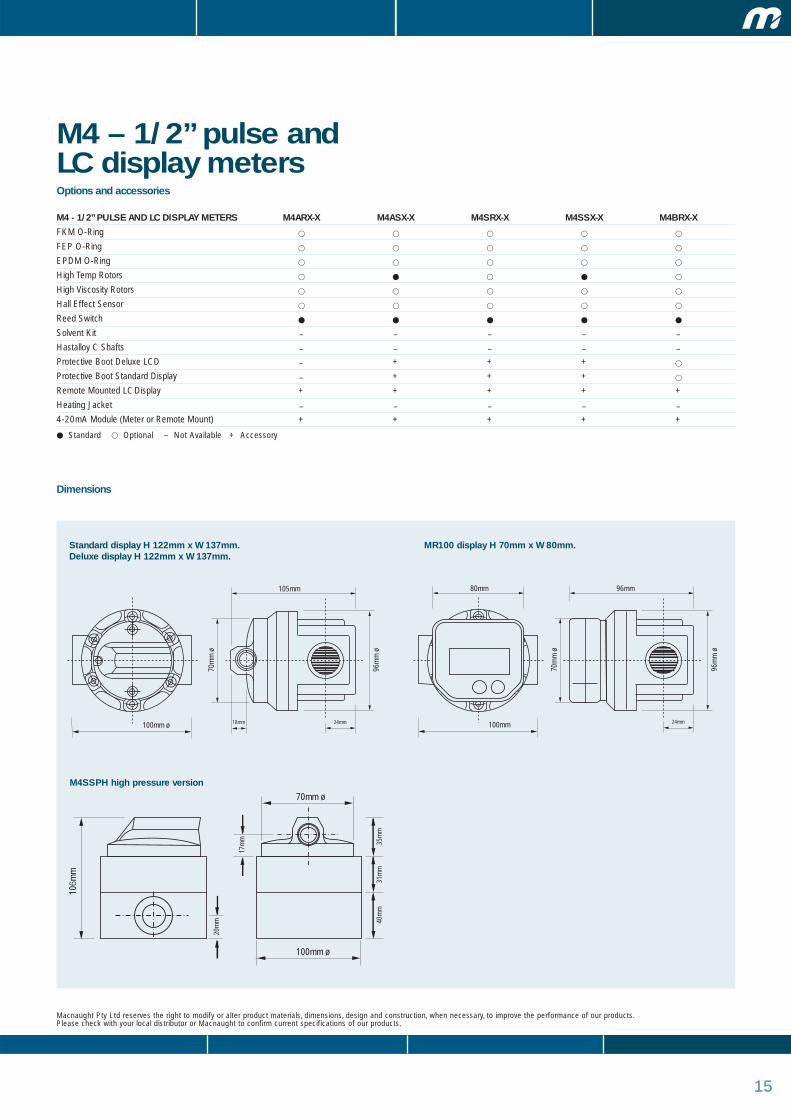
M4 – 1/2” pulse and LC display meters
Macnaught Pty Ltd reserves the right to modify or alter product materials, dimensions, design and construction, when necessary, to improve the performance of our products. Please check with your local distributor or Macnaught to confirm current specifications of our products.
Standard display H 122mm x W 137mm. Deluxe display H 122mm x W 137mm.
Dimensions
100mm ø
105mm
70m
m ø
96m
m ø
18mm 24mm 100mm
96mm 80mm
70m
m ø
96m
m ø
24mm
MR100 display H 70mm x W 80mm.
M4SSPH high pressure version
100mm ø
70mm ø
106m
m
40m
m31
mm
35m
m
20m
m
17m
m

161616
positive displacement flow meters
M4 – 1/2” meters withmechanical registerThe M4 is a low to medium flow range model. It is a compact meterthat has the ability to handle a wide range of fluid viscosities withexceptional levels of repeatability and durability.
Features
• Compact size.
• Easy to read and operate mechanical register.
• Flexibility of installation options (e.g. can be mounted horizontally or vertically; no flowconditioning required).
• Low pressure drop allows for economical pump selection or gravity flow applications.
• Meter construction enables fast and easy on-site servicing without removal fromapplication.
• Meter accuracy is verified by a factory calibration check after which an individualmetrology report is issued.
• Meter design minimises the number of wearable and replaceable parts and extendsproduct life.
Specification:
Model M4
Meter Type Meter With Mechanical Register
Meter Body Material Aluminium / 316 Stainless Steel / Bronze
Wetted Components:
Rotor Material PPS Only
Shafts 316 Stainless Steel
O'ring NBR (Nitrile)
Flow Rate Ranges
(Litres Per Minute/US Gallons Per Minute)
Above 5 cPs 2 To 30 / 0.5 To 8
Below 5 cPs 3 To 25 / 0.8 To 6.60
Accuracy- Within (Of Reading) +/- 1%
Repeatability 0.03%
Maximum Viscosity (Of Standard Model) 1000 Centipoise
Maximum Operating Pressure 3400kpa/ 34 Bar / 500 Psi
Max. Operating Temperature 80°C / 176°F, High Temp Option 120°C / 248°F
Recommended Mesh Strainer Size 60 Mesh
Mechanical Register
M4ARM-X
Port Size
To order flowmeter you must replace ‘X’ with the relevant number. This number will determinethe following specifications:
Port Size: Calibrated In:
1 = 1/2” BSP (F) ports Litres
2 = 1/2” NPT (F) ports US Gallons
PPS = Polyphenylene Sulfide Resins
MH450 Industrial Register
17
Options and accessories
M4 - 1/2” METERS WITH MECHANICAL REGISTER M4ARM-X M4SRM-X M4ARMI-X M4SRMI-X
FKM O-Ring � � � �
FEP O-Ring � � � �
EPDM O-Ring � � � �
High Temp Rotors � � � �
High Viscosity Rotors � � � �
Hall Effect Sensor – – – –
Reed Switch – – – –
Solvent Kit � � � �
Hastalloy C Shafts – – – –
Protective Boot + + – –
Remote Mounted LC Register – – – –
Heating Jacket – – – –
4-20mA Module – – – –
Protective Boot � �
� Standard � Optional – Not Available + Accessory
1717
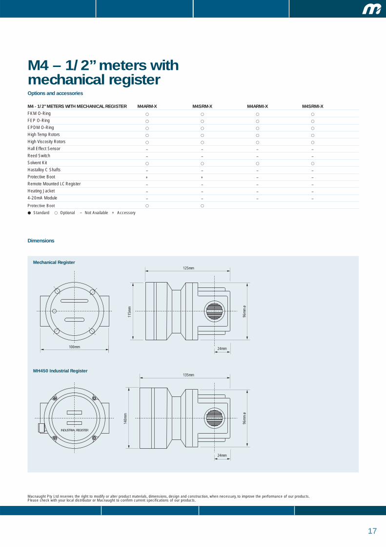
M4 – 1/2” meters withmechanical register
Macnaught Pty Ltd reserves the right to modify or alter product materials, dimensions, design and construction, when necessary, to improve the performance of our products. Please check with your local distributor or Macnaught to confirm current specifications of our products.
Dimensions
100mm
125mm
24mm
115m
m
96m
m ø
135mm
24mm
140m
m
96m
m ø
INDUSTRIAL REGISTER
Mechanical Register
MH450 Industrial Register
181818
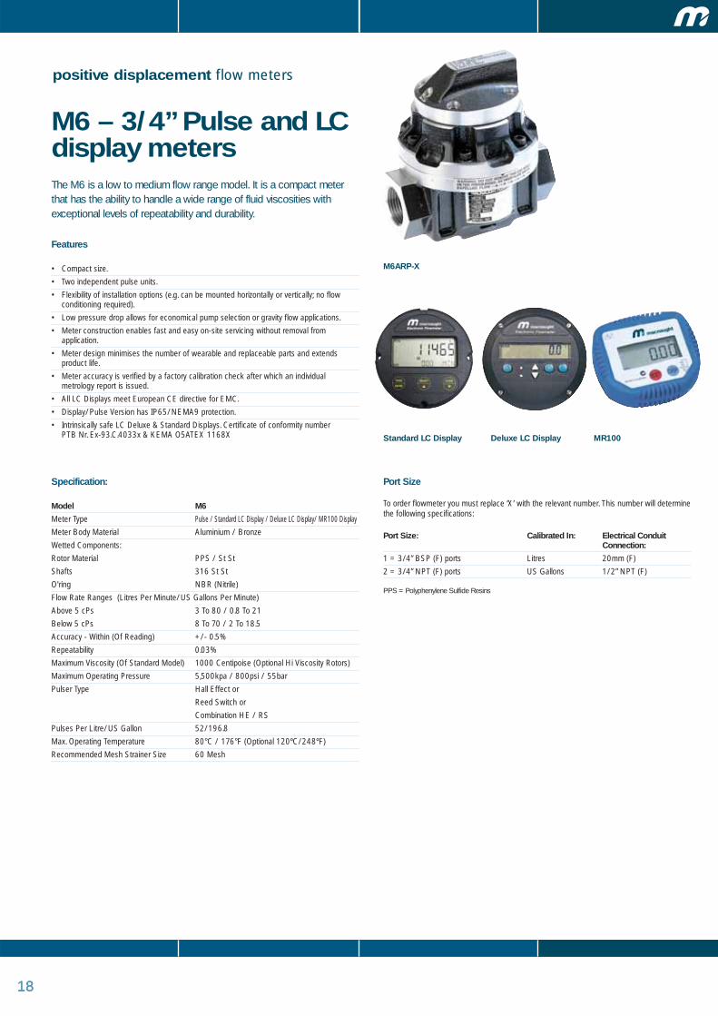
positive displacement flow meters
M6 – 3/4” Pulse and LCdisplay metersThe M6 is a low to medium flow range model. It is a compact meterthat has the ability to handle a wide range of fluid viscosities withexceptional levels of repeatability and durability.
Features
• Compact size.
• Two independent pulse units.
• Flexibility of installation options (e.g. can be mounted horizontally or vertically; no flowconditioning required).
• Low pressure drop allows for economical pump selection or gravity flow applications.
• Meter construction enables fast and easy on-site servicing without removal fromapplication.
• Meter design minimises the number of wearable and replaceable parts and extendsproduct life.
• Meter accuracy is verified by a factory calibration check after which an individualmetrology report is issued.
• All LC Displays meet European CE directive for EMC.
• Display/Pulse Version has IP65/NEMA9 protection.
• Intrinsically safe LC Deluxe & Standard Displays. Certificate of conformity number PTB Nr. Ex-93.C.4033x & KEMA O5ATEX 1168X
Specification:
Model M6
Meter Type Pulse / Standard LC Display / Deluxe LC Display/ MR100 Display
Meter Body Material Aluminium / Bronze
Wetted Components:
Rotor Material PPS / St St
Shafts 316 St St
O'ring NBR (Nitrile)
Flow Rate Ranges (Litres Per Minute/US Gallons Per Minute)
Above 5 cPs 3 To 80 / 0.8 To 21
Below 5 cPs 8 To 70 / 2 To 18.5
Accuracy - Within (Of Reading) +/- 0.5%
Repeatability 0.03%
Maximum Viscosity (Of Standard Model) 1000 Centipoise (Optional Hi Viscosity Rotors)
Maximum Operating Pressure 5,500kpa / 800psi / 55bar
Pulser Type Hall Effect or
Reed Switch or
Combination HE / RS
Pulses Per Litre/US Gallon 52/196.8
Max. Operating Temperature 80°C / 176°F (Optional 120ºC/248ºF)
Recommended Mesh Strainer Size 60 Mesh
M6ARP-X
Port Size
To order flowmeter you must replace ‘X’ with the relevant number. This number will determinethe following specifications:
Port Size: Calibrated In: Electrical Conduit Connection:
1 = 3/4” BSP (F) ports Litres 20mm (F)
2 = 3/4” NPT (F) ports US Gallons 1/2” NPT (F)
PPS = Polyphenylene Sulfide Resins
Deluxe LC DisplayStandard LC Display MR100
19
Options and accessories
M6 - 3/4” PULSE AND LC DISPLAY METERS M6ARP-X M6ASP-X M6ARG-X M6ARD-X M6ARE-X
FKM O-Ring � � � � �
FEP O-Ring � � � � �
EPDM O-Ring � � � � �
High Temp Rotors � – – – –
High Viscosity Rotors � � � � �
Hall Effect Sensor � � � � �
Reed Switch � � � � �
Solvent Kit – – – – –
Hastalloy C Shafts – – – – –
Protective Boot Deluxe LCD – – + – +
Protective Boot Standard Display � � – – –
Remote Mounted LC Display + + + + +
Heating Jacket � � � � �
4-20mA Module Meter or Remote Mount + + + + +
� Standard � Optional – Not Available + Accessory
1919
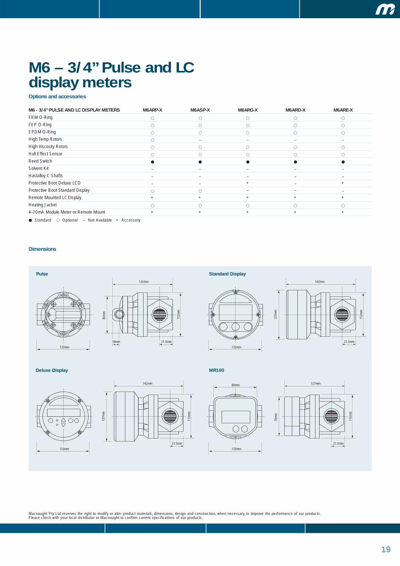
M6 – 3/4” Pulse and LCdisplay meters
Macnaught Pty Ltd reserves the right to modify or alter product materials, dimensions, design and construction, when necessary, to improve the performance of our products. Please check with your local distributor or Macnaught to confirm current specifications of our products.
Dimensions
133mm
21.5mm18mm
112m
m
86m
m
126mm
133mm
80mm
21.5mm
112m
m
70m
m
127mm
133mm
21.5mm
112m
m
137m
m
142mm
133mm
21.5mm
112m
m
137m
m
142mm
Pulse Standard Display
Deluxe Display MR100

20
positive displacement flow meters
M7 – 1” Pulse and LCdisplay metersThe M7 is a specialised meter for aggressive chemicals and waterbased products. It has the ability to handle a wide range of fluidviscosities with exceptional levels of repeatability and durability.
Features
• Compact size.
• Two independent pulse units.
• Flexibility of installation options (e.g. can be mounted horizontally or vertically; no flowconditioning required).
• Low pressure drop allows for economical pump selection or gravity flow applications.
• Meter construction enables fast and easy on-site servicing without removal fromapplication.
• Meter design minimises the number of wearable and replaceable parts and extendsproduct life.
• Meter accuracy is verified by factory calibration check after which an individual metrology report is issued.
• LCD & Pulse Version have IP65/NEMA9 protection.
Specification:
Model M7
Meter Type Pulse / Standard LC Display / Deluxe LC Display/ MR100 LC Display
Meter Body Material PPS
Wetted Components:
Rotor Material PPS / St St
Shafts 316 St St Or Hastalloy C
(Optional Meter Model Designation - C)
O'ring NBR (Nitrile)
Flow Rate Ranges (Litres Per Minute/US Gallons Per Minute)
Above 5 cPs 3 To 80 / 0.8 To 21
Below 5 cPs 8 To 70 / 2 To 18.5
Accuracy- Within (Of Reading) +/- 0.5%
Repeatability 0.03%
Maximum Viscosity (Of Standard Model) 1000 Centipoise (Optional High Viscosity Rotors)
Maximum Operating Pressure 1000kpa / 150psi / 10bar
Pulser Type Hall Effect or
Reed Switch or
Combination HE / RS
Pulses Per Litre/Us Gallon 52/196.8
Max. Operating Temperature 80°C / 176°F (120ºC / 248ºF S/S Rotors)
Recommended Mesh Strainer Size 60 Mesh
M7RRP-X
Port Size
To order flowmeter you must replace ‘X’ with the relevant number. This number will determinethe following specifications:
Port Size: Calibrated In: Electrical Conduit Connection:
1 = 1” BSP (F) ports Litres 20mm (F)
2 = 1” NPT (F) ports US Gallons 1/2” NPT (F)
PPS = Polyphenylene Sulfide Resins
Special Models
M7ARPH-XR High Pressure Version (Aluminium)
Threaded Versions Only 250 Bar / 3625 PSI Maximum Working Pressure
Available Options: Pulse LC Displays, ST ST Rotors, Hi Viscosity Rotors
Deluxe LC DisplayStandard LC Display MR100

21
Options and accessories
M7 - 1” PULSE AND LC DISPLAY METERS M7RRP-X M7RRG-X M7RRE-X M7RRD-X
FKM O-Ring � � � �
FEP O-Ring � � � �
EPDM O-Ring � � � �
High Temp Rotors – – – –
High Viscosity Rotors – – – –
Hall Effect Sensor � � � �
Reed Switch � � � �
Solvent Kit – – – –
Hastalloy C Shafts � � � �
Protective Boot Deluxe LCD – + + –
Protective Boot Standard Display – � – –
Remote Mounted LC Display + + + +
Heating Jacket – – – –
Stainless Steel Rotors (Hi Temp 120ºC/248ºF) � � � �
4-20mA Module Meter or Remote Mount + + + +
� Standard � Optional – Not Available + Accessory
M7 – 1” Pulse and LCdisplay meters
Macnaught Pty Ltd reserves the right to modify or alter product materials, dimensions, design and construction, when necessary, to improve the performance of our products. Please check with your local distributor or Macnaught to confirm current specifications of our products.
Dimensions
108mm
30mm18mm
100m
m
70m
m
120mm
108mm
80mm
70m
m
108mm
108mm
137m
m137mm
108mm
137m
m
137mm
30mm
100m
m
30mm
100m
m
30mm
100m
m
116mm ø
70mm ø
113m
m
113m
m
17mm
Pulse Standard Display
Deluxe Display MR100
High Pressure Version
22222222
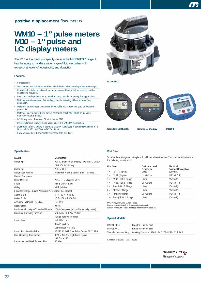
positive displacement flow meters
WM10 – 1” pulse meters M10 – 1” pulse and LC display metersThe M10 is the medium capacity meter in the M-SERIESTM range. Ithas the ability to handle a wide range of fluid viscosities withexceptional levels of repeatability and durability.
Features
• Compact size.
• Two independent pulse units which can be linked to allow doubling of the pulse output.
• Flexibility of installation options (e.g. can be mounted horizontally or vertically; no flowconditioning required).
• Low pressure drop allows for economical pump selection or gravity flow applications.
• Meter construction enables fast and easy on-site servicing without removal fromapplication.
• Meter design minimises the number of wearable and replaceable parts and extendsproduct life.
• Meter accuracy is verified by a factory calibration check after which an individualmetrology report is issued.
• LC Display meets European CE directive for EMC.
• Deluxe/Standard Displays Pulse Version have IP65/NEMA9 protection.
• Intrinsically safe LC Deluxe & Standard Displays. Certificate of conformity numbers PTBNr. Ex-93.C.4033x & KEMA O5ATEX1168X
• Pulse versions have Flameproof Certification AUS Ex2377x
Specification:
Model M10/WM10
Meter Type Pulse / Standard LC Display / Deluxe LC Display
/ MR100 LC Display
Meter Type Pulse / LCD
Meter Body Material Aluminium / 316 Stainless Steel / Bronze
Wetted Components:
Rotor Material PPS / 316 Stainless Steel
Shafts 316 Stainless Steel
O'ring NBR (Nitrile)
Flow Rate Ranges (Litres Per Minute/US Gallons Per Minute)
Above 5 cPs 6 To 120 / 1.6 To 32
Below 5 cPs 10 To 100 / 2.6 To 26
Accuracy - Within (Of Reading) +/- 0.5%
Repeatability 0.03%
Maximum Viscosity (Of Standard Model) 1000 Centipoise (optional hi viscosity rotors)
Maximum Operating Pressure 5500kpa/ 800 Psi/ 55 Bar
Flange Rule Where Fitted
Pulser Type Hall Effect or
Reed Switch or
Combination HE / RS
Pulses Per Litre/Us Gallon 36 /136.3 With Dual Pulse Output 72 / 272.6
Max. Operating Temperature 80°C / 176°F / High Temp Option 120°C / 248°F
Recommended Mesh Strainer Size 60 Mesh
M10ARP-X
Port Size
To order flowmeter you must replace ‘X’ with the relevant number. This number will determinethe following specifications:
Port Size: Calibrated and Electrical Display In: Conduit Connection:
1 = 1” BSP (F) ports Litres 20mm (F)
2 = 1” NPT (F) ports US Gallons 1/2” NPT (F)
3 = 1” ANSI 150lb Flange Litres 20mm (F)
4 = 1” ANSI 150lb Flange US Gallons 1/2” NPT (F)
5 = 25mm DIN 16 Flange Litres 20mm (F)
6 = 1” Triclover Flange Litres 20mm (F)
7 = 1” Triclover Flange US Gallons 1/2” NPT (F)
13=25mm JIS 10K Flange Litres 20mm (F)
PPS = Polyphenylene Sulfide Resins Bronze = Available in 1 or 2 port configuration only Note: See relevant Flange Technical Information on page 45
Flameproof Approval
Special Models
M10ARPH-X High Pressure Version
M10SSPH-X High Pressure Version
Threaded Versions Only Working Pressure 13800 kPa / 2000 PSI / 138 BAR
Available Options: All as listed
Deluxe LC DisplayStandard LC Display MR100
2323
Options and accessories
WM10 - 1” PULSE AND LC DISPLAY METERS WM10ARX-X WM10ASX-X WM10SRX-X WM10SSX-X WM10BRX-XM10 - 1” PULSE AND LC DISPLAY METERS M10ARX-X M10ASX-X M10SRX-X M10SSX-X M10BRX-XFKM O-Ring � � � � �
FEP O-Ring � � � � �
EPDM O-Ring � � � � �
High Temp Rotors � � � � �
High Viscosity Rotors � � � � �
Hall Effect Sensor � � � � �
Reed Switch � � � � �
Solvent Kit – – – – –
Hastalloy C Shafts – – – – –
Protective Boot Deluxe LCD + + + + +
Protective Boot Standard Display + + + + +
Remote Mounted LC Display + + + + +
Heating Jacket + + + + +
4-20mA Module + + + + +
� Standard � Optional – Not Available + Accessory
2323
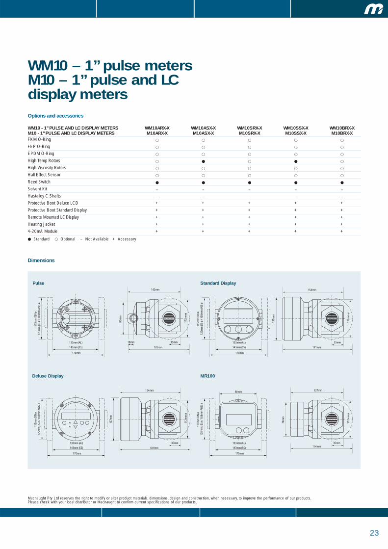
WM10 – 1” pulse meters M10 – 1” pulse and LCdisplay meters
Macnaught Pty Ltd reserves the right to modify or alter product materials, dimensions, design and construction, when necessary, to improve the performance of our products. Please check with your local distributor or Macnaught to confirm current specifications of our products.
Dimensions
143mm (SS)
133mm (AL)
170mm
35mm18mm
112m
mø
86m
m
115m
m D
IN ø
12
5mm
JIS
ø /
108m
m A
NIS
ø11
5mm
DIN
ø
125m
m J
IS ø
/ 10
8mm
ANI
S ø
115m
m D
IN ø
12
5mm
JIS
ø /
108m
m A
NIS
ø11
5mm
DIN
ø
125m
m J
IS ø
/ 10
8mm
ANI
S ø
143mm (SS)
133mm (AL)
170mm
142mm
165mm 181mm
164mm
80mm
35mm
112m
m ø
70m
m
137mm
35mm
112m
m ø
137m
m
154mm
143mm (SS)
133mm (AL)
170mm
143mm (SS)
133mm (AL)
170mm
181mm
35mm
112m
m ø
137m
m
154mm
Pulse Standard Display
Deluxe Display MR100
2424242424
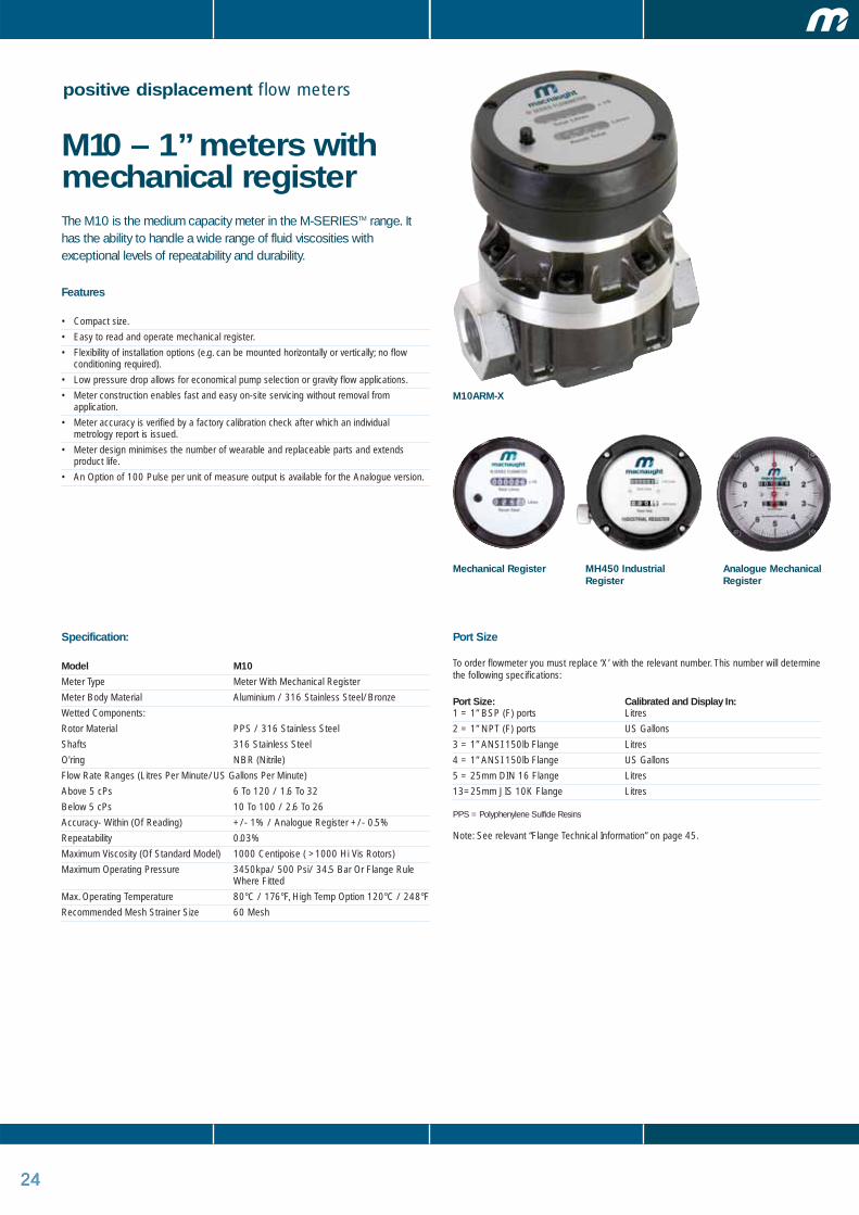
positive displacement flow meters
M10 – 1” meters withmechanical registerThe M10 is the medium capacity meter in the M-SERIESTM range. Ithas the ability to handle a wide range of fluid viscosities withexceptional levels of repeatability and durability.
Features
• Compact size.
• Easy to read and operate mechanical register.
• Flexibility of installation options (e.g. can be mounted horizontally or vertically; no flowconditioning required).
• Low pressure drop allows for economical pump selection or gravity flow applications.
• Meter construction enables fast and easy on-site servicing without removal fromapplication.
• Meter accuracy is verified by a factory calibration check after which an individualmetrology report is issued.
• Meter design minimises the number of wearable and replaceable parts and extendsproduct life.
• An Option of 100 Pulse per unit of measure output is available for the Analogue version.
Specification:
Model M10
Meter Type Meter With Mechanical Register
Meter Body Material Aluminium / 316 Stainless Steel/Bronze
Wetted Components:
Rotor Material PPS / 316 Stainless Steel
Shafts 316 Stainless Steel
O'ring NBR (Nitrile)
Flow Rate Ranges (Litres Per Minute/US Gallons Per Minute)
Above 5 cPs 6 To 120 / 1.6 To 32
Below 5 cPs 10 To 100 / 2.6 To 26
Accuracy- Within (Of Reading) +/- 1% / Analogue Register +/- 0.5%
Repeatability 0.03%
Maximum Viscosity (Of Standard Model) 1000 Centipoise ( >1000 Hi Vis Rotors)
Maximum Operating Pressure 3450kpa/ 500 Psi/ 34.5 Bar Or Flange Rule Where Fitted
Max. Operating Temperature 80°C / 176°F, High Temp Option 120°C / 248°F
Recommended Mesh Strainer Size 60 Mesh
Mechanical Register Analogue MechanicalRegister
M10ARM-X
Port Size
To order flowmeter you must replace ‘X’ with the relevant number. This number will determinethe following specifications:
Port Size: Calibrated and Display In:1 = 1” BSP (F) ports Litres
2 = 1” NPT (F) ports US Gallons
3 = 1” ANSI 150lb Flange Litres
4 = 1” ANSI 150lb Flange US Gallons
5 = 25mm DIN 16 Flange Litres
13=25mm JIS 10K Flange Litres
PPS = Polyphenylene Sulfide Resins
Note: See relevant “Flange Technical Information” on page 45.
MH450 IndustrialRegister
252525
Options and accessoriesM10 - 1” METERS WITH MECHANICAL REGISTER M10ARM-X M10ASM-X M10SRM-X M10SSM-X M10BRM-X
FKM O-Ring � � � � �
FEP O-Ring � � � � �
EPDM O-Ring � � � � �
High Temp Rotors � � � � �
High Viscosity Rotors � � � � �
Hall Effect Sensor – – – – –
Reed Switch – – – – –
Solvent Kit � � � � �
Hastalloy C Shafts – – – – –
Analogue Register � � � � �
MH 450 Register � � � � �
Pulse Kit P500 + + + + +
Remote Mounted LC Display – – – – –
Heating Jacket + + + + +
4-20mA Module – – – – –
Protective Boot Standard Mechanical Register + + + + +
� Standard � Optional – Not Available + Accessory
2525
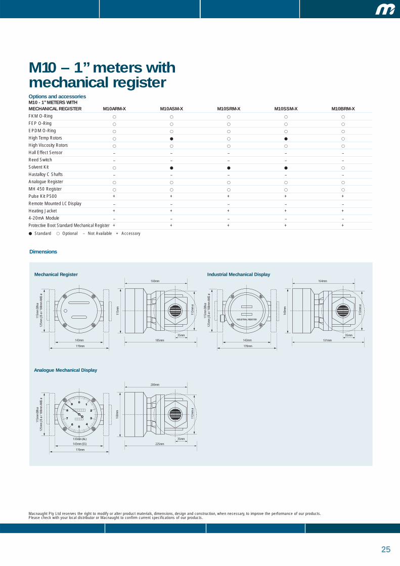
M10 – 1” meters withmechanical register
Macnaught Pty Ltd reserves the right to modify or alter product materials, dimensions, design and construction, when necessary, to improve the performance of our products. Please check with your local distributor or Macnaught to confirm current specifications of our products.
Dimensions
143mm
170mm
191mm
35mm
112m
m ø
140m
m164mm
143mm
170mm
185mm
35mm
112m
m ø
115m
m
160mm
143mm (SS)
133mm (AL)
170mm
225mm
35mm
112m
m ø
160m
m
200mm
INDUSTRIAL REGISTER
115m
m D
IN ø
12
5mm
JIS
ø /
108m
m A
NIS
ø11
5mm
DIN
ø
125m
m J
IS ø
/ 10
8mm
ANI
S ø
115m
m D
IN ø
12
5mm
JIS
ø /
108m
m A
NIS
ø
Mechanical Register Industrial Mechanical Display
Analogue Mechanical Display

26
positive displacement flow meters
WM40 – 1 1/2” pulse meters M40 – 1 1/2” pulse and LC display metersThe M40 is the medium to large capacity meter in the M-SERIESTM range.It has the ability to handle a wide range of fluid viscosities with exceptionallevels of repeatability and durability.
Features
• Compact size.
• Two independent pulse units which can be linked to allow doubling of the pulse output.
• Flexibility of installation options (e.g. can be mounted horizontally or vertically; no flowconditioning required).
• Low pressure drop allows for economical pump selection or gravity flow applications.
• Meter construction enables fast and easy on-site servicing without removal from application.
• Meter design minimises the number of wearable and replaceable parts and extends productlife.
• Meter accuracy is verified by a factory calibration check after which an individual metrology report is issued.
• Both LC Displays meets European CE directive fot EMC.
• Deluxe/Standard Displays and Pulse Version have IP65/NEMA9 protection.
• Intrinsically safe LC Deluxe & Standard Displays. Certificate of conformity number PTB Nr.
Ex-93.C.4033x & KEMA O5ATEX1168X
• Pulse Versions have Flameproof Certification. AUS Ex2377x
Specifications
Model M40/WM40
Meter Type Pulse / Standard LC Display / Deluxe LC Display
Meter Body Material Aluminium / 316 Stainless Steel / Bronze
Wetted Components:
Rotor Material PPS / 316 Stainless Steel
Shafts 316 Stainless Steel
O'ring NBR (Nitrile)
Flow Rate Ranges (Litres Per Minute/US Gallons Per Minute)
Above 5 cPs 10 To 250 / 2.6 To 66
Below 5 cPs 15 To 235 / 4 To 62
Accuracy- Within (Of Reading) +/- 0.5%
Repeatability 0.03%
Maximum Viscosity (Of Standard Model) 1000 Centipoise ( > 1000 Hi Vis Rotors)
Maximum Operating Pressure 5500 kpa/800psi/55bar or flange rule where fitted (*PEI 1800kpa/260psi/18bar)
Pulser Type Hall Effect Or
Reed Switch Or
Combination HE /RS
Pulses Per Litre/Us Gallon 14.5 / 54.9
Max. Operating Temperature 80°C / 176°F, High Temp Option 120°C / 248°F
Recommended Mesh Strainer Size 60 Mesh
Port Size
To order flowmeter you must replace ‘X’ with the relevant number. This number will determinethe following specifications:
Port Size: Calibrated and Electrical Conduit Display In: Connection:
1 = 1 1/2” BSP (F) ports Litres 20mm (F)
2 = 1 1/2” NPT (F) ports US Gallons 1/2” NPT (F)
3 = 1 1/2” ANSI 150lb Flange Litres 20mm (F)
4 = 1 1/2” ANSI 150lb Flange US Gallons 1/2” NPT (F)
5 = 40mm DIN 16 Flange Litres 20mm (F)
6 = 1 1/2” Triclover Flange Litres 20mm(F)
7 = 1 1/2” Triclover Flange US Gallons 1/2” NPT (F)
9 = 600LB ANSI Flange Litre 20mm(F)
13=40mm JIS 10K flange Litres 20mm(F)
PPS = Polyphenylene Sulfide Resins
Note: See relevant “Flange Technical Information” on page 45.
Deluxe LC DisplayStandard LC Display
M40ARP-X
Flameproof Approval*European common market - pressure equipment directive requirements
MR100
27
positive displacement flow meters
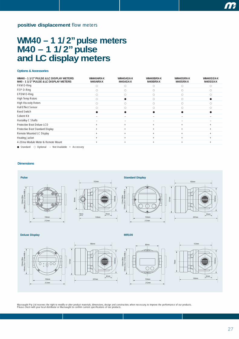
WM40 – 1 1/2” pulse metersM40 – 1 1/2” pulse and LC display metersOptions & Accessories
WM40 - 1 1/2” PULSE & LC DISPLAY METERS WM40ARX-X WM40ASX-X WM40BRX-X WM40SRX-X WM40SSX-XM40 - 1 1/2” PULSE & LC DISPLAY METERS M40ARX-X M40ASX-X M40BRX-X M40SRX-X M40SSX-XFKM O-Ring � � � � �
FEP O-Ring � � � � �
EPDM O-Ring � � � � �
High Temp Rotors � � � � �
High Viscosity Rotors � � � � �
Hall Effect Sensor � � � � �
Reed Switch � � � � �
Solvent Kit – – – – –
Hastalloy C Shafts – – – – –
Protective Boot Deluxe LCD + + + + +
Protective Boot Standard Display + + + + +
Remote Mounted LC Display + + + + +
Heating Jacket + + + + +
4-20ma Module Meter & Remote Mount + + + + +
� Standard � Optional – Not Available + Accessory
Macnaught Pty Ltd reserves the right to modify or alter product materials, dimensions, design and construction, when necessary, to improve the performance of our products. Please check with your local distributor or Macnaught to confirm current specifications of our products.
Dimensions
150mm
212mm
45mm18mm
144m
mø
86m
m
150m
m D
IN ø
14
0mm
JIS
ø /
127m
m A
NIS
ø15
0mm
DIN
ø
140m
m J
IS ø
/ 12
7mm
ANI
S ø
150m
m D
IN ø
14
0mm
JIS
ø /
127m
m A
NIS
ø11
5mm
DIN
ø
125m
m J
IS ø
/ 10
8mm
ANI
S ø
150mm
212mm
163mm
190mm 207mm
190mm
80mm
45mm
144m
m ø
70m
m
163mm
45mm14
4mm
ø
137m
m
180mm
150mm
212mm
150mm
212mm
207mm
45mm
144m
m ø
137m
m
180mm
Pulse Standard Display
Deluxe Display MR100

28
positive displacement flow meters
M40 – 1 1/2” metreswith mechanical registerThe M40 is the medium to large capacity meter in the M-SERIESTM
range. It has the ability to handle a wide range of fluid viscosities withexceptional levels of repeatability and durability.
Features
• Compact size.
• Easy to read and operate mechanical register.
• Flexibility of installation options (e.g. can be mounted horizontally or vertically; no flowconditioning required).
• Low pressure drop allows for economical pump selection or gravity flow applications.
• Meter construction enables fast and easy on-site servicing without removal fromapplication.
• Meter accuracy is verified by a factory calibration check after which an individualmetrology report is issued.
• Meter design minimises the number of wearable and replaceable parts and extendsproduct life.
• An Option of 100 Pulse per unit of measure output is available for the Analogue version.
Specifications
Model M40
Meter Type Meter With Mechanical Register
Meter Body Material Aluminium / 316 Stainless Steel / Bronze
Wetted Components:
Rotor Material PPS / 316 Stainless Steel
Shafts 316 Stainless Steel
O'ring NBR (Nitrile)
Flow Rate Ranges (Litres Per Minute/Us Gallons Per Minute)
Above 5 cPs 10 to 250/2.6 to 66
Below 5 cPs 235/4 to 62
Accuracy - Within (Of Reading) +/- 1% / Analogue Register +/- 0.5%
Repeatability 0.03%
Maximum Viscosity (Of Standard Model) 1000 Centipoise ( > 1000 Hi Vis Rotors)
Maximum Operating Pressure 3500 kpa/500psi/35bar or flange rule where fitted (*PEI 1800kpa/260psi/18bar)
Max. Operating Temperature 80°C / 176°F, High Temp Option 120°C / 248°F
Recommended Mesh Strainer Size 60 Mesh
Port Size
To order flowmeter you must replace ‘X’ with the relevant number. This number will determinethe following specifications:
Port Size: Calibrated and Display In:
1 = 1 1/2” BSP (F) ports Litres
2 = 1 1/2” NPT (F) ports US Gallons
3 = 1 1/2” ANSI 150lb Flange Litres
4 = 1 1/2” ANSI 150lb Flange US Gallons
5 = 40mm DIN 16 Flange Litres
9 = 1 1/2” ANSI 600lb Flange Litres
13=40mm JIS 10K Flange Litres
PPS = Polyphenylene Sulfide Resins
Note: See relevant “Flange Technical Information” on page 49.
M40SRM-X
*EU - pressure equipment directive 97/23/EC
Mechanical Register Analogue MechanicalRegister
MH450 IndustrialRegister

29
positive displacement flow meters
M40 – 1 1/2” metres withmechanical registerOptions & Accessories
M40 - 1 1/2” METERS WITH MECHANICAL REGISTER M40ARM-X M40ASM-X M40SRM-X M40SSM-X
FKM O-Ring � � � �
FEP O-Ring � � � �
EPDM O-Ring � � � �
High Temp Rotors � � � �
High Viscosity Rotors � � � �
Hall Effect Sensor – – – –
Reed Switch – – – –
Solvent Kit � � � �
Hastalloy C Shafts – – – –
Analogue Register � � � �
MH450 Register � � � �
Pulsar Kit P500 + + + +
Remote Mounted LC Display – – – –
Heating Jacket + + + +
Protection Boot + + + +
4-20ma Module – – – –
� Standard � Optional – Not Available + Accessory
Macnaught Pty Ltd reserves the right to modify or alter product materials, dimensions, design and construction, when necessary, to improve the performance of our products. Please check with your local distributor or Macnaught to confirm current specifications of our products.
Dimensions
150mm
133mm (AL)
212mm
217mm
45mm
144m
m ø
140m
m190mm
150mm
212mm
211mm
45mm
144m
m ø
115m
m
177mm
150mm
212mm
260mm
45mm
144m
m ø
160m
m
228mm
INDUSTRIAL REGISTER
150m
m D
IN ø
14
0mm
JIS
ø /
127m
m A
NIS
ø
150m
m D
IN ø
14
0mm
JIS
ø /
127m
m A
NIS
ø
150m
m D
IN ø
14
0mm
JIS
ø /
127m
m A
NIS
ø
Mechanical Register Industrial Mechanical Register
Analogue Mechanical Register
30
positive displacement flow meters
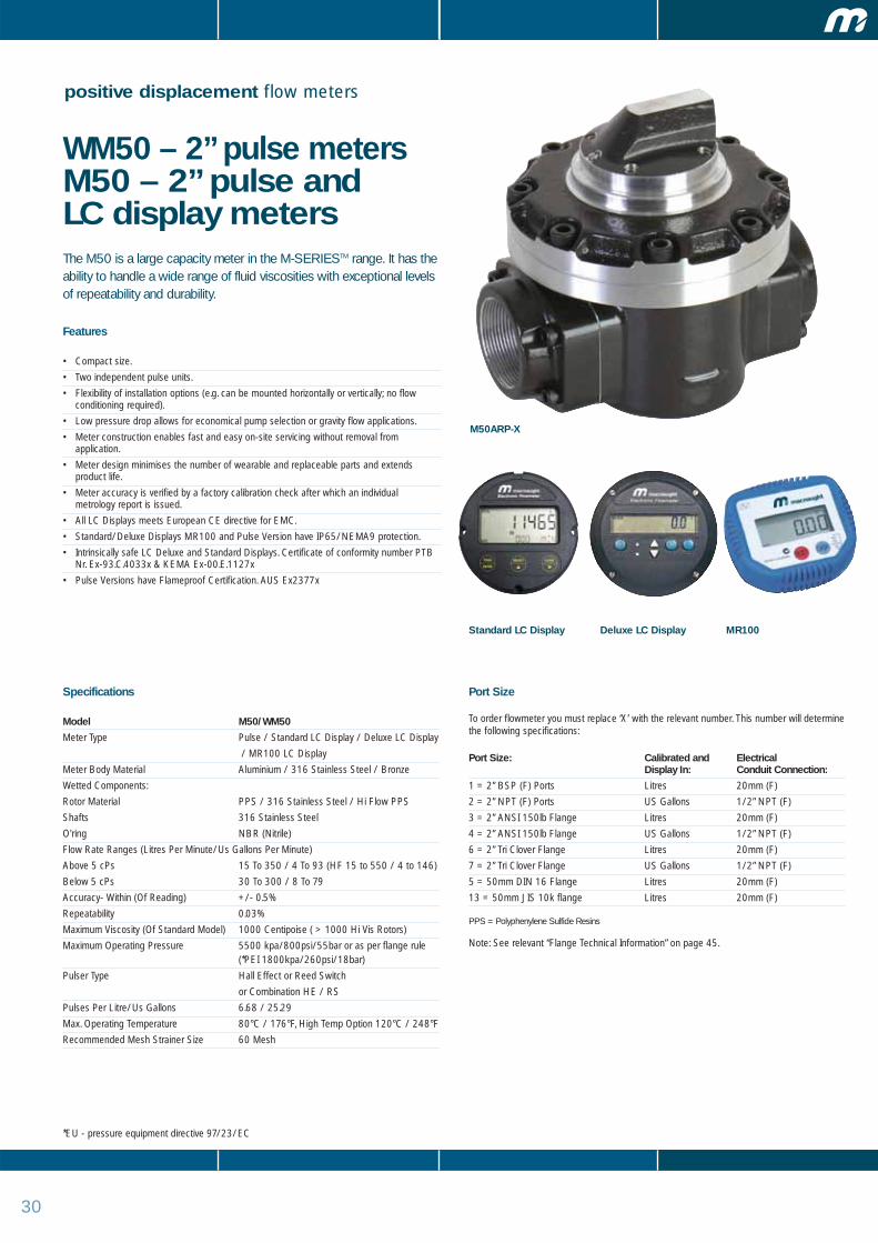
WM50 – 2” pulse meters M50 – 2” pulse and LC display metersThe M50 is a large capacity meter in the M-SERIESTM range. It has theability to handle a wide range of fluid viscosities with exceptional levelsof repeatability and durability.
Features
• Compact size.
• Two independent pulse units.
• Flexibility of installation options (e.g. can be mounted horizontally or vertically; no flowconditioning required).
• Low pressure drop allows for economical pump selection or gravity flow applications.
• Meter construction enables fast and easy on-site servicing without removal fromapplication.
• Meter design minimises the number of wearable and replaceable parts and extendsproduct life.
• Meter accuracy is verified by a factory calibration check after which an individualmetrology report is issued.
• All LC Displays meets European CE directive for EMC.
• Standard/Deluxe Displays MR100 and Pulse Version have IP65/NEMA9 protection.
• Intrinsically safe LC Deluxe and Standard Displays. Certificate of conformity number PTBNr. Ex-93.C.4033x & KEMA Ex-00.E.1127x
• Pulse Versions have Flameproof Certification. AUS Ex2377x
Specifications
Model M50/WM50
Meter Type Pulse / Standard LC Display / Deluxe LC Display
/ MR100 LC Display
Meter Body Material Aluminium / 316 Stainless Steel / Bronze
Wetted Components:
Rotor Material PPS / 316 Stainless Steel / Hi Flow PPS
Shafts 316 Stainless Steel
O'ring NBR (Nitrile)
Flow Rate Ranges (Litres Per Minute/Us Gallons Per Minute)
Above 5 cPs 15 To 350 / 4 To 93 (HF 15 to 550 / 4 to 146)
Below 5 cPs 30 To 300 / 8 To 79
Accuracy- Within (Of Reading) +/- 0.5%
Repeatability 0.03%
Maximum Viscosity (Of Standard Model) 1000 Centipoise ( > 1000 Hi Vis Rotors)
Maximum Operating Pressure 5500 kpa/800psi/55bar or as per flange rule (*PEI 1800kpa/260psi/18bar)
Pulser Type Hall Effect or Reed Switch
or Combination HE / RS
Pulses Per Litre/Us Gallons 6.68 / 25.29
Max. Operating Temperature 80°C / 176°F, High Temp Option 120°C / 248°F
Recommended Mesh Strainer Size 60 Mesh
Port Size
To order flowmeter you must replace ‘X’ with the relevant number. This number will determinethe following specifications:
Port Size: Calibrated and Electrical Display In: Conduit Connection:
1 = 2” BSP (F) Ports Litres 20mm (F)
2 = 2” NPT (F) Ports US Gallons 1/2” NPT (F)
3 = 2” ANSI 150lb Flange Litres 20mm (F)
4 = 2” ANSI 150lb Flange US Gallons 1/2” NPT (F)
6 = 2” Tri Clover Flange Litres 20mm (F)
7 = 2” Tri Clover Flange US Gallons 1/2” NPT (F)
5 = 50mm DIN 16 Flange Litres 20mm (F)
13 = 50mm JIS 10k flange Litres 20mm (F)
PPS = Polyphenylene Sulfide Resins
Note: See relevant “Flange Technical Information” on page 45.
M50ARP-X
*EU - pressure equipment directive 97/23/EC
Deluxe LC DisplayStandard LC Display MR100

31
positive displacement flow meters
WM50 – 2” pulse meters M50 – 2” pulse andLC display metersOptions & Accessories
WM50 - 2” PULSE AND LC DISPLAY METERS WM50ARX-X WM50SRX-X WM50SSX-X WM50ASX-XM50 - 2” PULSE AND LC DISPLAY METERS M50ARX-X M50SRX-X M50SSX-X M50ASX-X
FKM O-Ring � � � �
FEP O-Ring � � � �
EPDM O-Ring � � � �
High Temp Rotors � � � �
High Viscosity Rotors � � � �
Hall Effect Sensor � � � �
Reed Switch � � � �
Solvent Kit – – – –
Hastalloy C Shafts – – – –
Protective Boot Deluxe LCD + + + +
Protective Boot Standard Display + + + +
Remote Mounted LC Display + + + +
Heating Jacket + + + +
4-20ma Module Meter or Remote Mount + + + +
� Standard � Optional – Not Available + Accessory
Macnaught Pty Ltd reserves the right to modify or alter product materials, dimensions, design and construction, when necessary, to improve the performance of our products. Please check with your local distributor or Macnaught to confirm current specifications of our products.
Dimensions
210mm
264mm
55mm18mm
178m
mø
86m
m
155m
m D
IN ø
16
5mm
JIS
ø /
152m
m A
NIS
ø
193mm
223mm 210mm
264mm
55mm17
8mm
ø
137m
m
155m
m D
IN ø
16
5mm
JIS
ø /
152m
m A
NIS
ø
213mm
238mm
210mm 210mm
264mm
55mm
178m
mø
137m
m
155m
m D
IN ø
16
5mm
JIS
ø /
152m
m A
NIS
ø
213mm
238mm
80mm
264mm
55mm
178m
mø
70m
m
155m
m D
IN ø
16
5mm
JIS
ø /
152m
m A
NIS
ø
198mm
223mm
Pulse Standard Display
Deluxe Display MR100

32
positive displacement flow meters
M50 – 2” meters with mechanical registerThe M50 is the medium to large capacity meter in the M-SERIESTM
range. It has the ability to handle a wide range of fluid viscosities withexceptional levels of repeatability and durability.
Features
• Compact size.
• Easy to read and operate mechanical registers.
• Flexibility of installation options (e.g. can be mounted horizontally or vertically; no flowconditioning required).
• Low pressure drop allows for economical pump selection or gravity flow applications.
• Meter construction enables fast and easy on-site servicing without removal fromapplication.
• Meter accuracy is verified by a factory calibration check after which an individualmetrology report is issued.
• Meter design minimises the number of wearable and replaceable parts and extendsproduct life.
• An Option of 100 Pulses per unit of measure output is available for the Analogue version.
Specifications
Model M50
Meter Type Meter With Mechanical Register
Meter Body Material Aluminium / 316 Stainless Steel / Bronze
Wetted Components:
Rotor Material PPS / 316 Stainless Steel / Hi Flow PPS
Shafts 316 Stainless Steel
O'ring NBR (Nitrile)
Flow Rate Ranges (Litres Per Minute/US Gallons Per Minute)
Above 5 Cps 15 to 350/ 4 to 93 HF 15 to 550/4 to 146
Below 5 Cps 33 to 300/9 to 79 HF 30 to 500/9 to 132
Accuracy- Within (Of Reading) +/- 1% / Analogue Register +/- 0.5%Repeatability 0.03%
Maximum Viscosity (Of Standard Model) 1000 Centipoise ( > 1000 Hi Vis Rotors)
Maximum Operating Pressure 3500 kpa/800psi/55bar or as per flange rule (*PEI 1800kpa/260psi/18bar)
Max. Operating Temperature 80°C / 176°F, High Temp Option 120°C / 248°F
Recommended Mesh Strainer Size 60 Mesh
Port Size
To order flowmeter you must replace ‘X’ with the relevant number. This number will determinethe following specifications:
Port Size: Calibrated and Display In:
1 = 2” BSP (F) Ports Litres
2 = 2” NPT (F) Ports US Gallons
3 = 2” ANSI 150lb Flange Litres
4 = 2” ANSI 150lb Flange US Gallons
5 = 50mm DIN 16 Flange Litres
13=50mm JIS 10k flange Litres
PPS = Polyphenylene Sulfide Resins
Note: See relevant “Flange Technical Information” on page 45.
M50ARM-X
*EU - pressure equipment directive 97/23/EC
Mechanical Register Analogue MechanicalRegister
MH450 IndustrialRegister
33
positive displacement flow meters
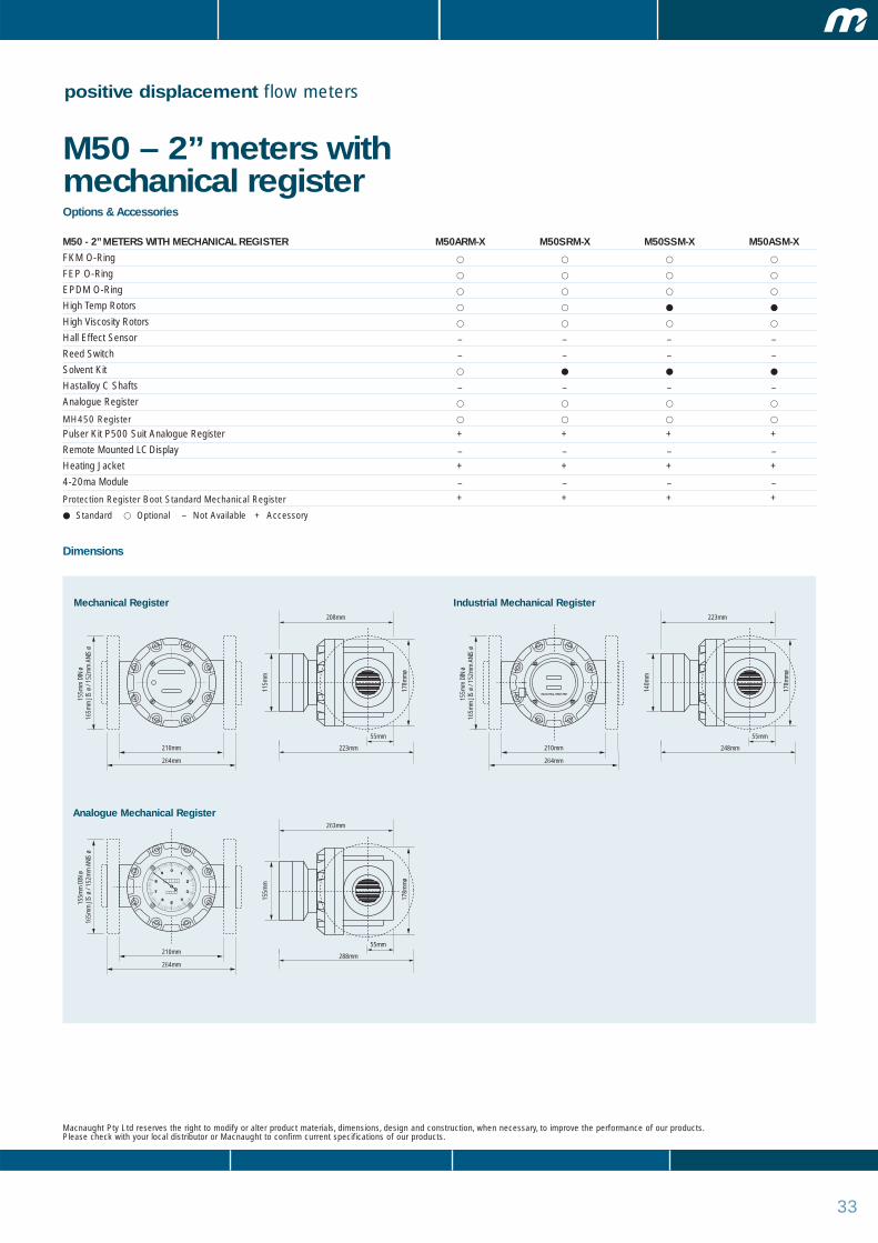
M50 – 2” meters with mechanical registerOptions & Accessories
M50 - 2” METERS WITH MECHANICAL REGISTER M50ARM-X M50SRM-X M50SSM-X M50ASM-X
FKM O-Ring � � � �
FEP O-Ring � � � �
EPDM O-Ring � � � �
High Temp Rotors � � � �
High Viscosity Rotors � � � �
Hall Effect Sensor – – – –
Reed Switch – – – –
Solvent Kit � � � �
Hastalloy C Shafts – – – –
Analogue Register � � � �
MH450 Register � � � �
Pulser Kit P500 Suit Analogue Register + + + +
Remote Mounted LC Display – – – –
Heating Jacket + + + +
4-20ma Module – – – –
Protection Register Boot Standard Mechanical Register + + + +
� Standard � Optional – Not Available + Accessory
Macnaught Pty Ltd reserves the right to modify or alter product materials, dimensions, design and construction, when necessary, to improve the performance of our products. Please check with your local distributor or Macnaught to confirm current specifications of our products.
Dimensions
210mm
264mm
55mm
178m
mø
115m
m
155m
m D
IN ø
16
5mm
JIS
ø /
152m
m A
NIS
ø
208mm
223mm 210mm
264mm
155m
m D
IN ø
16
5mm
JIS
ø /
152m
m A
NIS
ø
210mm
264mm
155m
m D
IN ø
16
5mm
JIS
ø /
152m
m A
NIS
ø
INDUSTRIAL REGISTER
55mm
178m
mø
140m
m
223mm
248mm
55mm
178m
mø
155m
m
263mm
288mm
Mechanical Register Industrial Mechanical Register
Analogue Mechanical Register
34
positive displacement flow meters
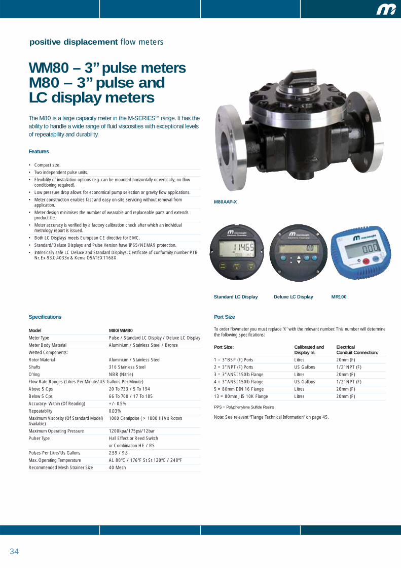
WM80 – 3” pulse meters M80 – 3” pulse and LC display metersThe M80 is a large capacity meter in the M-SERIESTM range. It has theability to handle a wide range of fluid viscosities with exceptional levelsof repeatability and durability.
Features
• Compact size.
• Two independent pulse units.
• Flexibility of installation options (e.g. can be mounted horizontally or vertically; no flowconditioning required).
• Low pressure drop allows for economical pump selection or gravity flow applications.
• Meter construction enables fast and easy on-site servicing without removal fromapplication.
• Meter design minimises the number of wearable and replaceable parts and extendsproduct life.
• Meter accuracy is verified by a factory calibration check after which an individualmetrology report is issued.
• Both LC Displays meets European CE directive for EMC.
• Standard/Deluxe Displays and Pulse Version have IP65/NEMA9 protection.
• Intrinsically safe LC Deluxe and Standard Displays. Certificate of conformity number PTBNr. Ex-93.C.4033x & Kema O5ATEX1168X
Specifications
Model M80/WM80
Meter Type Pulse / Standard LC Display / Deluxe LC Display
Meter Body Material Aluminium / Stainless Steel / Bronze
Wetted Components:
Rotor Material Aluminium / Stainless Steel
Shafts 316 Stainless Steel
O'ring NBR (Nitrile)
Flow Rate Ranges (Litres Per Minute/US Gallons Per Minute)
Above 5 Cps 20 To 733 / 5 To 194
Below 5 Cps 66 To 700 / 17 To 185
Accuracy- Within (Of Reading) +/- 0.5%
Repeatability 0.03%
Maximum Viscosity (Of Standard Model) 1000 Centipoise ( > 1000 Hi Vis RotorsAvailable)
Maximum Operating Pressure 1200kpa/175psi/12bar
Pulser Type Hall Effect or Reed Switch
or Combination HE / RS
Pulses Per Litre/Us Gallons 2.59 / 9.8
Max. Operating Temperature AL 80°C / 176°F St St 120ºC / 248ºF
Recommended Mesh Strainer Size 40 Mesh
Port Size
To order flowmeter you must replace ‘X’ with the relevant number. This number will determinethe following specifications:
Port Size: Calibrated and Electrical Display In: Conduit Connection:
1 = 3” BSP (F) Ports Litres 20mm (F)
2 = 3” NPT (F) Ports US Gallons 1/2” NPT (F)
3 = 3” ANSI 150lb Flange Litres 20mm (F)
4 = 3” ANSI 150lb Flange US Gallons 1/2” NPT (F)
5 = 80mm DIN 16 Flange Litres 20mm (F)
13 = 80mm JIS 10K Flange Litres 20mm (F)
PPS = Polyphenylene Sulfide Resins
Note: See relevant “Flange Technical Information” on page 45.
M80AAP-X
Deluxe LC DisplayStandard LC Display MR100
35
positive displacement flow meters
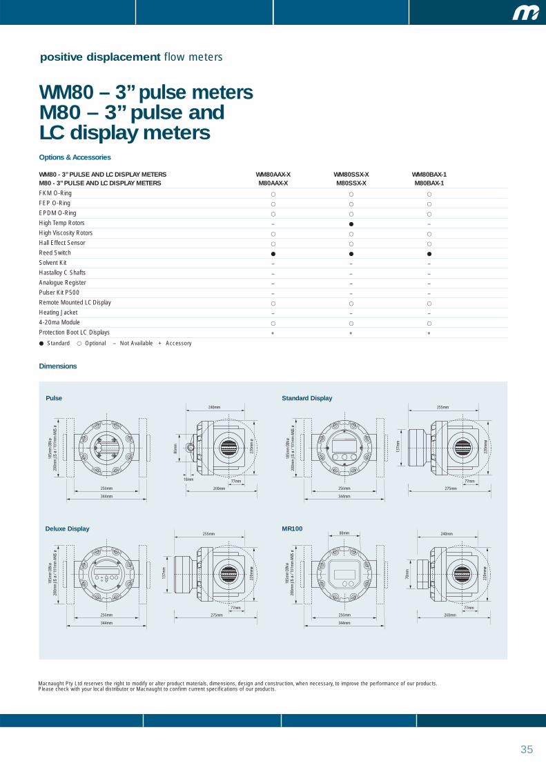
WM80 – 3” pulse meters M80 – 3” pulse and LC display metersOptions & Accessories
WM80 - 3” PULSE AND LC DISPLAY METERS WM80AAX-X WM80SSX-X WM80BAX-1M80 - 3” PULSE AND LC DISPLAY METERS M80AAX-X M80SSX-X M80BAX-1
FKM O-Ring � � �
FEP O-Ring � � �
EPDM O-Ring � � �
High Temp Rotors – � –
High Viscosity Rotors � � �
Hall Effect Sensor � � �
Reed Switch � � �
Solvent Kit – – –
Hastalloy C Shafts – – –
Analogue Register – – –
Pulser Kit P500 – – –
Remote Mounted LC Display � � �
Heating Jacket – – –
4-20ma Module � � �
Protection Boot LC Displays + + +
� Standard � Optional – Not Available + Accessory
Macnaught Pty Ltd reserves the right to modify or alter product materials, dimensions, design and construction, when necessary, to improve the performance of our products. Please check with your local distributor or Macnaught to confirm current specifications of our products.
Dimensions
256mm
344mm
77mm18mm
220m
m ø
86m
m
185m
m D
IN ø
20
0mm
JIS
ø /
191m
m A
NIS
ø18
5mm
DIN
ø
200m
m J
IS ø
/ 19
1mm
ANI
S ø
185m
m D
IN ø
20
0mm
JIS
ø /
191m
m A
NIS
ø
240mm
260mm 256mm
344mm
77mm22
0mm
ø
137m
m
185m
m D
IN ø
20
0mm
JIS
ø /
191m
m A
NIS
ø
255mm
275mm
256mm 256mm
344mm
77mm
220m
mø
137m
m
255mm
275mm
80mm
344mm
77mm
220m
mø
70m
m
240mm
260mm
Pulse Standard Display
Deluxe Display MR100

36
positive displacement flow meters
M80 – 3” meters withmechanical displayThe M80 is the large capacity meter in the M-SERIESTM range. It hasthe ability to handle a wide range of fluid viscosities with exceptionallevels of repeatability and durability.
Features
• Compact size.
• Easy to read and operate mechanical display.
• Flexibility of installation options (e.g. can be mounted horizontally or vertically; no flowconditioning required).
• Low pressure drop allows for economical pump selection or gravity flow applications.
• Meter construction enables fast and easy on-site servicing without removal from application.
• Meter accuracy is verified by a factory calibration check after which an individualmetrology report is issued.
• Meter design minimises the number of wearable and replaceable parts and extendsproduct life.
• An Option of 10/100 Pulse per unit of measure output is available.
Specifications
Model M80
Meter Type Meter With Mechanical Display
Meter Body Material Aluminium / Bronze
Wetted Components:
Rotor Material Aluminium
Shafts 316 Stainless Steel
O'ring NBR (Nitrile)
Flow Rate Ranges (Litres Per Minute/US Gallons Per Minute)
Above 5 Cps 20 To 733 / 5 To 194
Below 5 Cps 66 To 616 / 17 To 163
Accuracy- Within (Of Reading) +/- 0.5%
Repeatability 0.03%
Maximum Viscosity (Of Standard Model) 1000 Centipoise ( > 1000 Hi Vis RotorsAvailable)
Maximum Operating Pressure 1200kpa/175psi/12bar
Max. Operating Temperature 80°C / 176°F
Recommended Mesh Strainer Size 40 Mesh
Port Size
To order flowmeter you must replace ‘X’ with the relevant number. This number will determinethe following specifications:
Port Size: Calibrated and Display In:
1 = 3” BSP (F) Ports Litres
2 = 3” NPT (F) Ports US Gallons
3 = 3” ANSI 150lb Flange Litres
4 = 3” ANSI 150lb Flange US Gallons
5 = 80mm DIN 16 Flange Litres
13 = 80mm JIS 10K Flange Litres
Note: See relevant “Flange Technical Information” on page 45.
Analogue Mechanical Display
M80AAMA-X
37
positive displacement flow meters
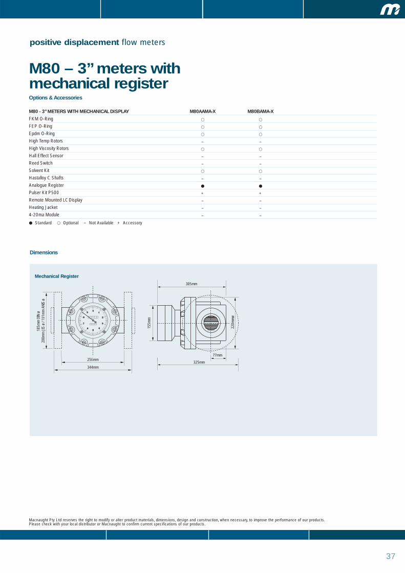
M80 – 3” meters withmechanical registerOptions & Accessories
M80 - 3” METERS WITH MECHANICAL DISPLAY M80AAMA-X M80BAMA-X
FKM O-Ring � �
FEP O-Ring � �
Epdm O-Ring � �
High Temp Rotors – –
High Viscosity Rotors � �
Hall Effect Sensor – –
Reed Switch – –
Solvent Kit � �
Hastalloy C Shafts – –
Analogue Register � �
Pulser Kit P500 + +
Remote Mounted LC Display – –
Heating Jacket – –
4-20ma Module – –
� Standard � Optional – Not Available + Accessory
Macnaught Pty Ltd reserves the right to modify or alter product materials, dimensions, design and construction, when necessary, to improve the performance of our products. Please check with your local distributor or Macnaught to confirm current specifications of our products.
Dimensions
256mm
344mm
185m
m D
IN ø
20
0mm
JIS
ø /
191m
m A
NIS
ø
77mm
220m
mø
155m
m
305mm
325mm
Mechanical Register

3838
positive displacement flow meters
WM100 – 4” pulse meters M100 – 4” pulse and LC display metersSuitable for fuels, lubricants and corrosive fluids (stainless steel only) toa viscosity of 1000cPs, the M100 is a 100mm (4"), high flow, ovalgear flowmeter and is capable of measuring fluid flows of up to1200LPM. The M100 is accurate to +/- 0.5% and providesexceptional levels of reliability and durability.
Features
• Easy to read and operate, resetable LC display options available
• Flexibility of installation options (eg: can be mounted horizontally or vertically - no flowconditioning required
• Low pressure drop allows for economical pump selection or gravity flow applications
• Meter construction enables fast and easy on-site servicing without removal fromapplication
• Meter accuracy is verified by a factory calibration check after which an individualmetrology report is issued
• Meter design minimises the number of wearable and replaceable parts and extendsproduct life
• Available with 4’ ANSI 150lb, JIS10K and DIN 16 flanges (modular construction) or 3’screwd BSP (F) or NPT (F)
• LCD optional displays meet European CE directive
• Standard/deluxe displays/MR100 and pulse version have IP65/NEMA9 protection
• Intrinsically safe LC display options available.
• 12 month warranty
Specifications
Model M100/WM100
Meter Type Pulse / Standard LC Display / Deluxe LC Display
Meter Body Material Aluminium / Stainless Steel / Bronze
Wetted Components:
Rotor Material Aluminium / Stainless Steel
Shafts 316 Stainless Steel
O'ring NBR (Nitrile)
Flow Rate Ranges (Litres Per Minute/US Gallons Per Minute)
Above 5 Cps 120 To 1200 / 32 - 317
Below 5 Cps 200 To 1200 / 53 - 317
Accuracy- Within (Of Reading) +/- 0.5%
Repeatability 0.03%
Maximum Viscosity (Of Standard Model) 1000cPs ( > 1000 cPs Hi Vis Rotors Available)
Maximum Operating Pressure 1200kpa/175psi/12bar
Pulser Type Hall Effect or Reed Switch
or Combination HE / RS
Pulses Per Litre/Us Gallons 2.32 / 8.782
Max. Operating Temperature AL 80ºC/176ºF St St 120ºC/248ºF
Recommended Mesh Strainer Size 40
Port Size
To order flowmeter you must replace ‘X’ with the relevant number. This number will determinethe following specifications:
Port Size: Calibrated and Electrical Display In: Conduit Connection:
3 = 4” ANSI 150lb Flange Litres 20mm (F)
4 = 4” ANSI 150lb Flange US Gallons 1/2 NPT (F)
5 = 100mm DIN 16 Flange Litres 20mm (F)
13 = 100mm JIS 10K Flange Litres 20mm (F)
14 = 3” ANSI 150LB Flange Litres 20mm (F)
15 = 3” ANSI 150LB Flange US Gallons 1/2 NPT (F)
16 = 3’ BSP (F) Port Litres 20mm (F)
17 = 3” NPT (F) Port US Gallons 1/2 NPT (F)
Note: See relevant “Flange Technical Information” on page 45.
M100AAP-X
Deluxe LC DisplayStandard LC Display MR100
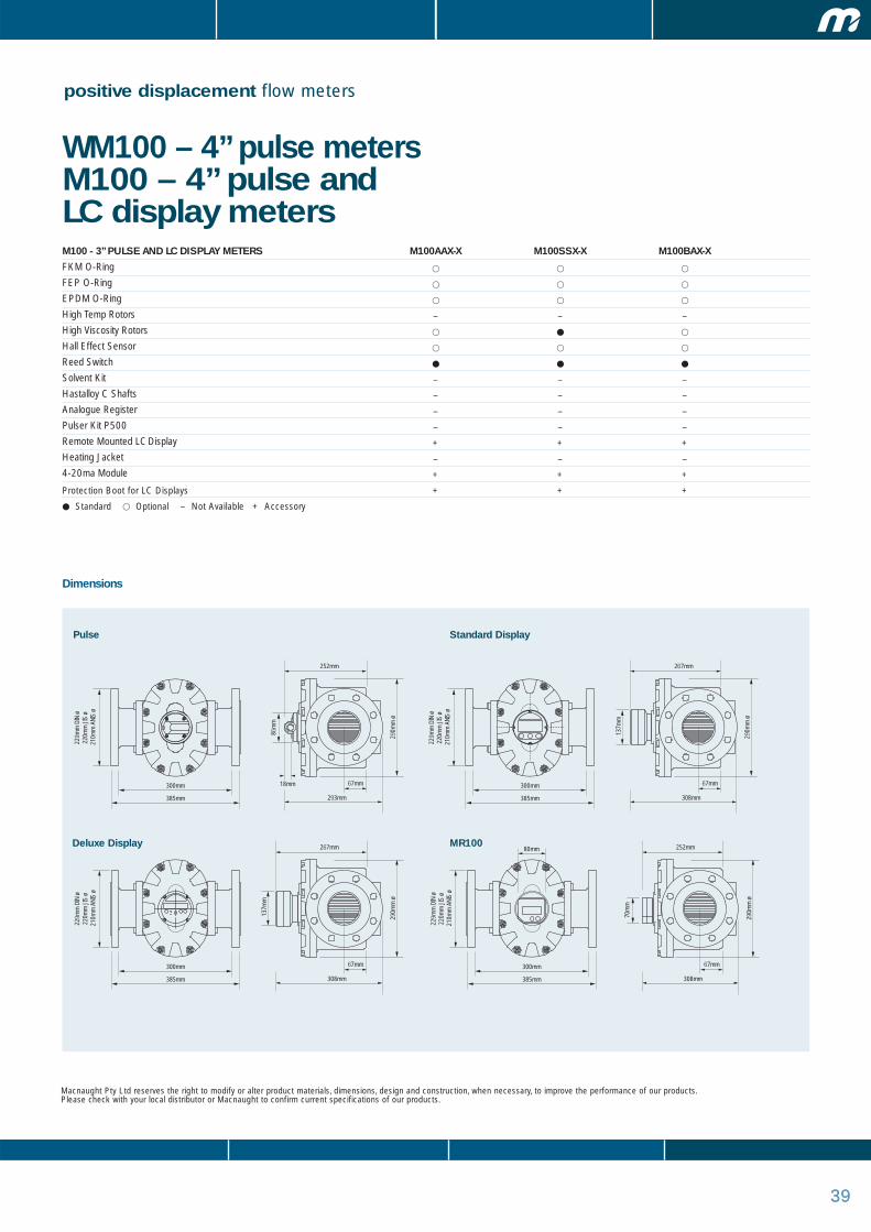
3939
positive displacement flow meters
WM100 – 4” pulse metersM100 – 4” pulse and LC display metersM100 - 3” PULSE AND LC DISPLAY METERS M100AAX-X M100SSX-X M100BAX-X
FKM O-Ring � � �
FEP O-Ring � � �
EPDM O-Ring � � �
High Temp Rotors – – –
High Viscosity Rotors � � �
Hall Effect Sensor � � �
Reed Switch � � �
Solvent Kit – – –
Hastalloy C Shafts – – –
Analogue Register – – –
Pulser Kit P500 – – –
Remote Mounted LC Display + + +
Heating Jacket – – –
4-20ma Module + + +
Protection Boot for LC Displays + + +
� Standard � Optional – Not Available + Accessory
Macnaught Pty Ltd reserves the right to modify or alter product materials, dimensions, design and construction, when necessary, to improve the performance of our products. Please check with your local distributor or Macnaught to confirm current specifications of our products.
Dimensions
300mm
385mm
229m
m D
IN ø
22
0mm
JIS
ø
210m
m A
NIS
ø
67mm18mm
290m
m ø
86m
m
252mm
293mm
80mm
300mm
385mm
229m
m D
IN ø
22
0mm
JIS
ø
210m
m A
NIS
ø
67mm
290m
m ø
137m
m
267mm
308mm
300mm
385mm
229m
m D
IN ø
22
0mm
JIS
ø
210m
m A
NIS
ø
67mm
290m
m ø
137m
m
267mm
308mm
300mm
385mm
229m
m D
IN ø
22
0mm
JIS
ø
210m
m A
NIS
ø
67mm
290m
m ø
70m
m
252mm
308mm
Pulse Standard Display
Deluxe Display MR100
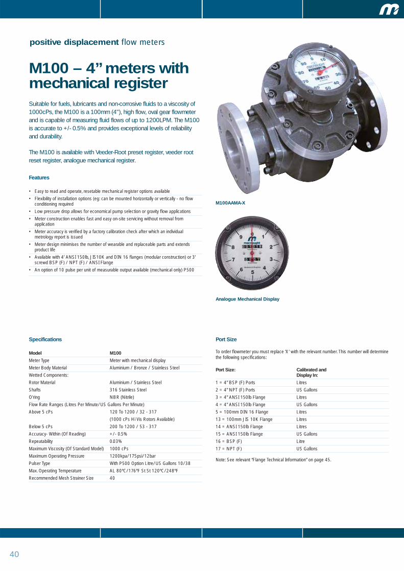
40
positive displacement flow meters
M100 – 4” meters withmechanical registerSuitable for fuels, lubricants and non-corrosive fluids to a viscosity of1000cPs, the M100 is a 100mm (4"), high flow, oval gear flowmeterand is capable of measuring fluid flows of up to 1200LPM. The M100is accurate to +/- 0.5% and provides exceptional levels of reliabilityand durability.
The M100 is available with Veeder-Root preset register, veeder rootreset register, analogue mechanical register.
Features
• Easy to read and operate, resetable mechanical register options available
• Flexibility of installation options (eg: can be mounted horizontally or vertically - no flowconditioning required
• Low pressure drop allows for economical pump selection or gravity flow applications
• Meter construction enables fast and easy on-site servicing without removal fromapplication
• Meter accuracy is verified by a factory calibration check after which an individualmetrology report is issued
• Meter design minimises the number of wearable and replaceable parts and extendsproduct life
• Available with 4’ ANSI 150lb, JIS10K and DIN 16 flanges (modular construction) or 3’screwd BSP (F) / NPT (F) / ANSI Flange
• An option of 10 pulse per unit of measurable output available (mechanical only) P500
Specifications
Model M100
Meter Type Meter with mechanical display
Meter Body Material Aluminium / Bronze / Stainless Steel
Wetted Components:
Rotor Material Aluminium / Stainless Steel
Shafts 316 Stainless Steel
O'ring NBR (Nitrile)
Flow Rate Ranges (Litres Per Minute/US Gallons Per Minute)
Above 5 cPs 120 To 1200 / 32 - 317
(1000 cPs Hi Vis Rotors Available)
Below 5 cPs 200 To 1200 / 53 - 317
Accuracy- Within (Of Reading) +/- 0.5%
Repeatability 0.03%
Maximum Viscosity (Of Standard Model) 1000 cPs
Maximum Operating Pressure 1200kpa/175psi/12bar
Pulser Type With P500 Option Litre/US Gallons 10/38
Max. Operating Temperature AL 80ºC/176ºF St St 120ºC/248ºF
Recommended Mesh Strainer Size 40
Port Size
To order flowmeter you must replace ‘X’ with the relevant number. This number will determinethe following specifications:
Port Size: Calibrated and Display In:
1 = 4” BSP (F) Ports Litres
2 = 4” NPT (F) Ports US Gallons
3 = 4” ANSI 150lb Flange Litres
4 = 4” ANSI 150lb Flange US Gallons
5 = 100mm DIN 16 Flange Litres
13 = 100mm JIS 10K Flange Litres
14 = ANSI 150lb Flange Litres
15 = ANSI 150lb Flange US Gallons
16 = BSP (F) Litre
17 = NPT (F) US Gallons
Note: See relevant “Flange Technical Information” on page 45.
Analogue Mechanical Display
M100AAMA-X

41
positive displacement flow meters
M100 – 4” meters withmechanical registerM100 - 4” METERS WITH MECHANICAL REGISTER M100AAMA-X M100BAMA-X
FKM O-Ring � �
FEP O-Ring � �
Epdm O-Ring � �
High Temp Rotors – –
High Viscosity Rotors � �
Hall Effect Sensor – –
Reed Switch – –
Solvent Kit � –
Hastalloy C Shafts – –
Analogue Register � �
Pulser Kit P500 + +
Remote Mounted LC Display – –
Heating Jacket – –
4-20ma Module – –
� Standard � Optional – Not Available + Accessory
Macnaught Pty Ltd reserves the right to modify or alter product materials, dimensions, design and construction, when necessary, to improve the performance of our products. Please check with your local distributor or Macnaught to confirm current specifications of our products.
Dimensions
300mm
385mm
229m
m D
IN ø
22
0mm
JIS
ø
210m
m A
NIS
ø
67mm
290m
m ø
137m
m
310mm
357mm
Mechanical Register
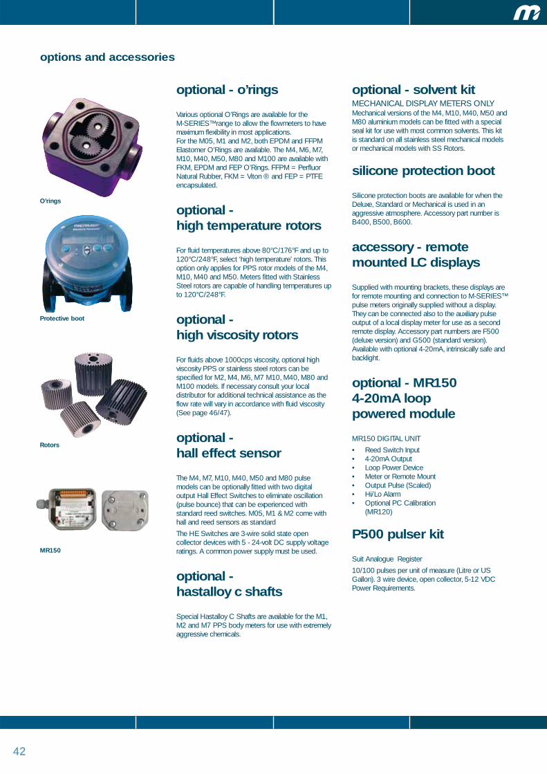
4242
options and accessories
optional - o’rings
Various optional O’Rings are available for the M-SERIES™ range to allow the flowmeters to havemaximum flexibility in most applications. For the M05, M1 and M2, both EPDM and FFPMElastomer O’Rings are available. The M4, M6, M7,M10, M40, M50, M80 and M100 are available withFKM, EPDM and FEP O’Rings. FFPM = PerfluorNatural Rubber, FKM = Viton ® and FEP = PTFEencapsulated.
optional - high temperature rotors
For fluid temperatures above 80°C/176°F and up to120°C/248°F, select ‘high temperature’ rotors. Thisoption only applies for PPS rotor models of the M4,M10, M40 and M50. Meters fitted with StainlessSteel rotors are capable of handling temperatures upto 120°C/248°F.
optional - high viscosity rotors
For fluids above 1000cps viscosity, optional highviscosity PPS or stainless steel rotors can bespecified for M2, M4, M6, M7 M10, M40, M80 andM100 models. If necessary consult your localdistributor for additional technical assistance as theflow rate will vary in accordance with fluid viscosity(See page 46/47).
optional - hall effect sensor
The M4, M7, M10, M40, M50 and M80 pulsemodels can be optionally fitted with two digitaloutput Hall Effect Switches to eliminate oscillation(pulse bounce) that can be experienced withstandard reed switches. M05, M1 & M2 come withhall and reed sensors as standard
The HE Switches are 3-wire solid state opencollector devices with 5 - 24-volt DC supply voltageratings. A common power supply must be used.
optional - hastalloy c shafts
Special Hastalloy C Shafts are available for the M1,M2 and M7 PPS body meters for use with extremelyaggressive chemicals.
optional - solvent kitMECHANICAL DISPLAY METERS ONLYMechanical versions of the M4, M10, M40, M50 andM80 aluminium models can be fitted with a specialseal kit for use with most common solvents. This kitis standard on all stainless steel mechanical modelsor mechanical models with SS Rotors.
silicone protection boot
Silicone protection boots are available for when theDeluxe, Standard or Mechanical is used in anaggressive atmosphere. Accessory part number isB400, B500, B600.
accessory - remotemounted LC displays
Supplied with mounting brackets, these displays arefor remote mounting and connection to M-SERIES™pulse meters originally supplied without a display.They can be connected also to the auxiliary pulseoutput of a local display meter for use as a secondremote display. Accessory part numbers are F500(deluxe version) and G500 (standard version).Available with optional 4-20mA, intrinsically safe andbacklight.
optional - MR150 4-20mA loop powered module
MR150 DIGITAL UNIT
• Reed Switch Input• 4-20mA Output• Loop Power Device• Meter or Remote Mount• Output Pulse (Scaled)• Hi/Lo Alarm• Optional PC Calibration
(MR120)
P500 pulser kit
Suit Analogue Register
10/100 pulses per unit of measure (Litre or USGallon). 3 wire device, open collector, 5-12 VDCPower Requirements.
O’rings
Protective boot
Rotors
MR150

4343
options and accessories
standard LC display
The standard LC Display is available on specific M4,M6, M7, M10, M40, M50, M80, M100 seriesmodels. It is also available as an accessory so it canbe used as a remote mounted display for any M-SERIES™ meter model supplied without a display e.g. M1, M2, M10ARP.
Features
• 7 Digit x17mm/ 0.67” and 11 Digit x8mm/ 0.31” LiquidCrystal Display.
• Display can be rotated in 90° steps.
• Flow rate display in litres or US gallons (according tomodel selected).
• 2 total displays - resettable and non-resettable, up to9999999999.9 litres or US gallons (according to modelselected).
• Fully progammable.
• Long life 3.2 volt (7 year) Lithium battery.
• Approved for hazardous locations
EEx ia11B/11C T6 (Kema Ex-00.E.1127x)
deluxe LC display
The Deluxe LC Display is available on specific M4,M6, M7, M10, M40, M50, M80, M100 seriesmodels. It is also available as an accessory so it canbe used as a remote mounted display for any M-SERIES™ meter model supplied without a display e.g. M1, M2, M10ARP.
Features
• 7 Digit x 12.7mm (1/2”) Liquid Crystal Display.
• Display can be rotated in 90° steps.
• Selectable flow rate display in litres or US gallons.
• 2 total displays.
• Up to 999999.9 litres or US gallons (resettable).
• Pre-settable batch control function up to 9999 units(99.99, 999.9 or 9999 optional settings).
• 10 preset batch quantity storage capacity.
• 3 digit cycle counter for batch dispensed.
• Single or dual valve actuation output to be used withappropriate trip amplifier.
• Factory set calibration constant (K Factor).
• Additional 9 calibration constants (K Factors) available for “in-the-field” settings.
• Up to 9999999 litres or US gallons (non-resettable).
• Switch output for trip amplifier.
• Long Life 3-volt Lithium battery.
• Approved for hazardous locations (standard battery only)EEx ia IIC T6 (PTB nr. Ex-93.C 4033X).
MR100 Digital Display• 6 x 12mm Digits• battery life 2 years• Grand Total / Reset Total /
Batch Total / Rate• Fully field programmable• 2 x AAA Alkaline batteries• Rate Units: sec, min, hr• IP65 Protection
(Optional PC Programme MR120)
A110 Rate Totaliser• Liquid Crystal Display• 7 x 17mm Digits• 11 x 8mm Digits• Total / Reset Total / Rate• 7 Year Battery Life• Scaled Pulse Output• 4 – 20mA Analogue Output• Fully Programmable• IP65 Protection• Optional Functions• Meter or Remote Mount
ER480 heavy duty metermounted LC display
The ER480 is an aluminium IP65 enclosuredesigned to take the full range of LC dispaly modelsfor meter mounted applications. The unit is providedwith 2 x 16mm and 1 x 20mm or 3 x 1/2" NPTscrewed conduit connections. Fitted with the latesteasy touch push buttons and large clear viewingwindow, The outside is protected by a long lastingepoxy finish and has provision for tamperproofsealing.
miscellaneous displays• Batch Control Units• Add/Subtract rate totalisers• Hi/Lo alarm rate totalisers
Options• Case Materials• Outputs• Communications• Temperature Compensation• Intrinsically Safe Certifications• Power Source AC/DC/Battery• Selectable Input Types• Backlight (LED Bi-Colour)
Standard LC Display
Deluxe LC Display
MR 100 Display
A110 Rate Totaliser
ER480 heavy duty meter mounted LC display

44
options and accessories
mechanical display - digitalThe Mechanical Display is available on specific M4, M10, M40 and M50 Seriesmeter models.
Features
• Litre or US gallon display (according to model selected).
• Two Totals;
Non Reset
Litre 9,999,990
USG 999,999
Reset
Litre 9,999USG 999.9
• Push button reset.
• Display can be rotated in 90° steps.
analogue mechanical registeris the latest addition to our range ofmechanical meters with sweep hand toindicate fluid quantity.
Features
• 156mm Diameter Face – 10/100 Litre or US Gallon PerNeedle Revolution.
• Non Reset Register – 9,999,999.9 minimum resolution0.1
• Reset Register – 9,999
• Optional Pulse Module – 100/1,000 pulses per revolution(10/100 pulses per unit of measure)
• Allows +/- 0.5% or better (of reading) accuracy.
• Rugged construction with toughened glass facia.
• Suitable for M10, M40, M50, M80 and M100 mechanicalmodels.
• See model numbering system for part numberidentification
MH450 IndustrialMechanical register
• Extra robust design
• Aluminium facia plate with toughened
glass exterior
• Aluminium reset knob
• Reset total 4 digits
• Grand total 6 digits
• IP65 Protection
• Suitable for M4 to M100 models
Analogue Mechanical Register
Veeder Root Display
MH450 Industrial Mechanical register
meter display specifications
High Pulse Resolution Meter
Veeder Root Display
• Reset Total 5 Digits
• Grand Total 8 Digits
• Suitable for M50 to M100 models
Strainer / Air Eliminator
MST11-CA1/MAE21-CA1Suits M10 to M50 with screwed or flangesconnections, 25mm, 40mm & 50mm
MST21-CA1/MAE21-CA1Suite M80 & M100 with screwed or flangedconnections, 80mm & 100mm
Strainer / Air Eliminator
Mechanical Display
high pulse resolutionmeters
The following models are available with a highresolution pulse output. Each pulse unit offers twopulse streams and directional signalM2 - 2,000 or 10,000 pulses per litre
M4 - 1,000 pulses per litre.
M10, M40, M50, M80 100 or 1,000 pulses per litre
Power: 5 - 12VDC
Output: Open Collector
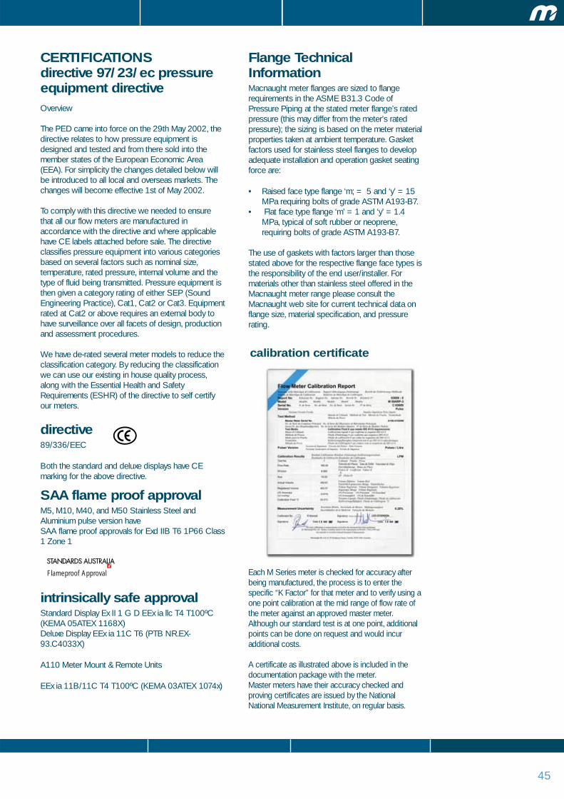
45
CERTIFICATIONSdirective 97/23/ec pressureequipment directive Overview
The PED came into force on the 29th May 2002, thedirective relates to how pressure equipment isdesigned and tested and from there sold into themember states of the European Economic Area(EEA). For simplicity the changes detailed below willbe introduced to all local and overseas markets. Thechanges will become effective 1st of May 2002.
To comply with this directive we needed to ensurethat all our flow meters are manufactured inaccordance with the directive and where applicablehave CE labels attached before sale. The directiveclassifies pressure equipment into various categoriesbased on several factors such as nominal size,temperature, rated pressure, internal volume and thetype of fluid being transmitted. Pressure equipment isthen given a category rating of either SEP (SoundEngineering Practice), Cat1, Cat2 or Cat3. Equipmentrated at Cat2 or above requires an external body tohave surveillance over all facets of design, productionand assessment procedures.
We have de-rated several meter models to reduce theclassification category. By reducing the classificationwe can use our existing in house quality process,along with the Essential Health and SafetyRequirements (ESHR) of the directive to self certifyour meters.
directive89/336/EEC
Both the standard and deluxe displays have CEmarking for the above directive.
SAA flame proof approvalM5, M10, M40, and M50 Stainless Steel andAluminium pulse version have SAA flame proof approvals for Exd IIB T6 1P66 Class1 Zone 1
intrinsically safe approvalStandard Display Ex II 1 G D EEx ia llc T4 T100ºC(KEMA 05ATEX 1168X)Deluxe Display EEx ia 11C T6 (PTB NR.EX-93.C4033X)
A110 Meter Mount & Remote Units
EEx ia 11B/11C T4 T100ºC (KEMA 03ATEX 1074x)
Flange TechnicalInformationMacnaught meter flanges are sized to flangerequirements in the ASME B31.3 Code ofPressure Piping at the stated meter flange’s ratedpressure (this may differ from the meter’s ratedpressure); the sizing is based on the meter materialproperties taken at ambient temperature. Gasketfactors used for stainless steel flanges to developadequate installation and operation gasket seatingforce are:
• Raised face type flange ‘m; = 5 and ‘y’ = 15 MPa requiring bolts of grade ASTM A193-B7.
• Flat face type flange ‘m’ = 1 and ‘y’ = 1.4 MPa, typical of soft rubber or neoprene, requiring bolts of grade ASTM A193-B7.
The use of gaskets with factors larger than thosestated above for the respective flange face types isthe responsibility of the end user/installer. Formaterials other than stainless steel offered in theMacnaught meter range please consult theMacnaught web site for current technical data onflange size, material specification, and pressurerating.
Flameproof Approval
calibration certificate
Each M Series meter is checked for accuracy afterbeing manufactured, the process is to enter thespecific “K Factor” for that meter and to verify using aone point calibration at the mid range of flow rate ofthe meter against an approved master meter.Although our standard test is at one point, additionalpoints can be done on request and would incuradditional costs.
A certificate as illustrated above is included in thedocumentation package with the meter.Master meters have their accuracy checked andproving certificates are issued by the NationalNational Measurement Institute, on regular basis.
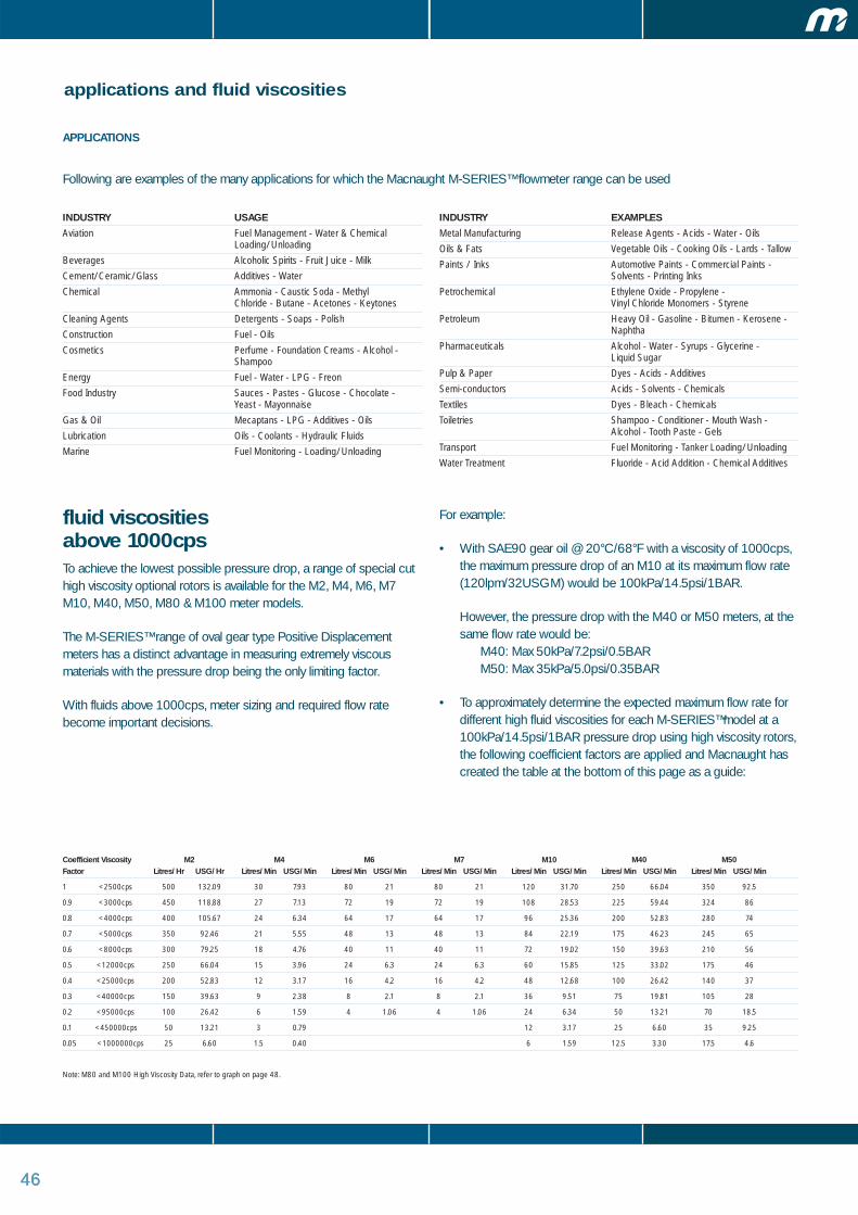
464646
applications and fluid viscosities
APPLICATIONS
Following are examples of the many applications for which the Macnaught M-SERIES™ flowmeter range can be used
fluid viscosities above 1000cpsTo achieve the lowest possible pressure drop, a range of special cuthigh viscosity optional rotors is available for the M2, M4, M6, M7M10, M40, M50, M80 & M100 meter models.
The M-SERIES™ range of oval gear type Positive Displacementmeters has a distinct advantage in measuring extremely viscousmaterials with the pressure drop being the only limiting factor.
With fluids above 1000cps, meter sizing and required flow ratebecome important decisions.
For example:
• With SAE90 gear oil @ 20°C/68°F with a viscosity of 1000cps,the maximum pressure drop of an M10 at its maximum flow rate(120lpm/32USGM) would be 100kPa/14.5psi/1BAR.
However, the pressure drop with the M40 or M50 meters, at thesame flow rate would be:
M40: Max 50kPa/7.2psi/0.5BARM50: Max 35kPa/5.0psi/0.35BAR
• To approximately determine the expected maximum flow rate fordifferent high fluid viscosities for each M-SERIES™model at a100kPa/14.5psi/1BAR pressure drop using high viscosity rotors,the following coefficient factors are applied and Macnaught hascreated the table at the bottom of this page as a guide:
Coefficient Viscosity M2 M4 M6 M7 M10 M40 M50Factor Litres/Hr USG/Hr Litres/Min USG/Min Litres/Min USG/Min Litres/Min USG/Min Litres/Min USG/Min Litres/Min USG/Min Litres/Min USG/Min
1 <2500cps 500 132.09 30 7.93 80 21 80 21 120 31.70 250 66.04 350 92.5
0.9 <3000cps 450 118.88 27 7.13 72 19 72 19 108 28.53 225 59.44 324 86
0.8 <4000cps 400 105.67 24 6.34 64 17 64 17 96 25.36 200 52.83 280 74
0.7 <5000cps 350 92.46 21 5.55 48 13 48 13 84 22.19 175 46.23 245 65
0.6 <8000cps 300 79.25 18 4.76 40 11 40 11 72 19.02 150 39.63 210 56
0.5 <12000cps 250 66.04 15 3.96 24 6.3 24 6.3 60 15.85 125 33.02 175 46
0.4 <25000cps 200 52.83 12 3.17 16 4.2 16 4.2 48 12.68 100 26.42 140 37
0.3 <40000cps 150 39.63 9 2.38 8 2.1 8 2.1 36 9.51 75 19.81 105 28
0.2 <95000cps 100 26.42 6 1.59 4 1.06 4 1.06 24 6.34 50 13.21 70 18.5
0.1 <450000cps 50 13.21 3 0.79 12 3.17 25 6.60 35 9.25
0.05 <1000000cps 25 6.60 1.5 0.40 6 1.59 12.5 3.30 17.5 4.6
Note: M80 and M100 High Viscosity Data, refer to graph on page 48.
INDUSTRY USAGE
Aviation Fuel Management - Water & Chemical Loading/Unloading
Beverages Alcoholic Spirits - Fruit Juice - Milk
Cement/Ceramic/Glass Additives - Water
Chemical Ammonia - Caustic Soda - Methyl Chloride - Butane - Acetones - Keytones
Cleaning Agents Detergents - Soaps - Polish
Construction Fuel - Oils
Cosmetics Perfume - Foundation Creams - Alcohol - Shampoo
Energy Fuel - Water - LPG - Freon
Food Industry Sauces - Pastes - Glucose - Chocolate - Yeast - Mayonnaise
Gas & Oil Mecaptans - LPG - Additives - Oils
Lubrication Oils - Coolants - Hydraulic Fluids
Marine Fuel Monitoring - Loading/Unloading
INDUSTRY EXAMPLES
Metal Manufacturing Release Agents - Acids - Water - Oils
Oils & Fats Vegetable Oils - Cooking Oils - Lards - Tallow
Paints / Inks Automotive Paints - Commercial Paints - Solvents - Printing Inks
Petrochemical Ethylene Oxide - Propylene - Vinyl Chloride Monomers - Styrene
Petroleum Heavy Oil - Gasoline - Bitumen - Kerosene -Naphtha
Pharmaceuticals Alcohol - Water - Syrups - Glycerine - Liquid Sugar
Pulp & Paper Dyes - Acids - Additives
Semi-conductors Acids - Solvents - Chemicals
Textiles Dyes - Bleach - Chemicals
Toiletries Shampoo - Conditioner - Mouth Wash - Alcohol - Tooth Paste - Gels
Transport Fuel Monitoring - Tanker Loading/Unloading
Water Treatment Fluoride - Acid Addition - Chemical Additives

474747
Met
er A
ccur
acy
Flow as % of maximum capacity
Gasoline 0.4 mPa . s
Water 1 mPa . s
Gas Oil 3 mPa . s
Fuel Oil 100 mPa . s
Pre
ssur
e D
rop,
kP
a
0
10
20
30
40
50
60
20 40 60 80 100
0
Pre
ssur
e Lo
ss (P
SI)
Pre
ssur
e Lo
ss (k
Pa)
Fluid Viscosity (mPa . s)Note: % = Percentage of maximum published flow of the meter model
16
14
12
10
8
6
4
2
0
110
97
83
69
55
41
28
14
0
0 100 10,000 1,000,00010 1,000 100,000
Standard Rotors 100%
High Viscosity Rotors
100%
Specia
l Cut
Rot
ors
50%
Specia
l Cut
Rot
ors
25%
Specia
l Cut
Rot
ors
10%
Spe
cial
Cut
Rot
ors
5%
Acc
urac
y %
Pre
ssur
e D
rop
(psi
)
Flow as % of maximum capacity
Note: For viscosities greater than 1000 mPa . s High Viscosity rotors are required
Gasoline 0.4 mPa . s
Water 1 mPa . s
Light Oil 20 mPa . s
A Heavy Oil 20 mPa . s
B Heavy Oil 100 mPa . s
C Heavy Oil 300 mPa . s
6000 CP
2000 CP
1000 CP
300 CP
100 CP
50 CP
10 CP5 CP
1 CP
15.0
13.2
12.0
10.5
9.0
7.5
6.0
4.5
3.0
1.5
+4.0
+3.0
+2.0
+1.0
0
–1.0
–2.0
–3.0
–4.0
0 10 20 30 40 50 60 70 80 90 100
1
1
2
2
3
3
4
5
6
45
6
General performance characteristics
High viscosity fluids pressure loss and maximum flows
Viscosity versus maximum flowrate - general viscosity/accuracy curves

48
Meter sizes M05, M1 & M2
Meter sizes M4, M10 & M40
Pre
ssur
e lo
ss (k
Pa)
Pre
ssur
e lo
ss (k
Pa)
Flow rate (%)
Flow rate (%)
0 25
30
20
10
50 75 100
0 25 50 75 100
Acc
urac
y %
+0.35
+0.15
0
–0.15
–0.35
Acc
urac
y % +0.15
0
–0.1580
60
40
20
Oil 20 mPa . sKerosene 1.2 mPa . sGasoline 0.4 mPa . s
Fuel Oil 13 mPa . sKerosene 1.2 mPa . sWater 1 mPa . sGasoline 0.4 mPa . s
Meter sizes M80
Pre
ssur
e lo
ss (k
Pa)
Flow rate (%)
0 25 50 75 100
Acc
urac
y % +0.15
0
–0.1580
60
40
20
Fuel Oil 13 mPa . sKerosene 1.2 mPa . sWater 1 mPa . sGasoline 0.4 mPa . s
Meter sizes M100
Pre
ssur
e lo
ss (k
Pa)
Flow rate (%)
0 25 50 75 100
Acc
urac
y % +0.15
0
–0.1580
60
40
20
Fuel Oil 13 mPa . sKerosene 1.2 mPa . sWater 1 mPa . sGasoline 0.4 mPa . s
Meter sizes M50
Pre
ssur
e lo
ss (k
Pa)
Flow rate (%)
0 25 50 75 100
Acc
urac
y % +0.15
0
–0.1560
50
40
30
20
10
Fuel Oil 13 mPa . sKerosene 1.2 mPa . sWater 1 mPa . sGasoline 0.4 mPa . s
Meter Errors and Pressure Losses

49
Meter Errors and Pressure Losses
Meter sizes M05, M1 & M2
Pre
ssur
e lo
ss (k
Pa)
Flow rate (%)
0 25
2
3
1
7.5
10 30
M05 M1 M2
20
102.5
5
50 75 100
Met
er e
rror
%
+0.35
+.015
0
–0.15
–.035
Oil 20 mPa . sKerosene 1.2 mPa . sGasoline 0.4 mPa . s
Flow rate (%)0 25 50 75 100
Pre
ssur
e lo
ss (k
Pa)
80
70
60
50
40
30
20
10
For Oil Service For Water Service
General Chemical Liquids Service
Meter error (%) with kerosene (1.2mPa . s)
Pressure losses with heavy oil (19mPa . s)
Pressure losses
Meter errors
Pre
ssur
e lo
ss (k
Pa)
Pre
ssur
e lo
ss (k
Pa)
Flow rate (%)
60
50
40
30
20
10
0 25 50 75 100
Flow rate (%)0 25 50 75 100
Met
er e
rror
%
Met
er e
rror
%
+0.5
0
–0.5
Met
er e
rror
%
+0.150
–0.15
+1.0
+0.5
0
–0.5
–1.0
15
10
5
Meter SizesM4M10M40M50M80M100
Meter SizesM4M7M10M40
Fuel Oil 13 mPa . sKerosene 1.2 mPa . sWater 1 mPa . sGasoline 0.4 mPa . s
Meter Sizes
M4/7M10M40M50
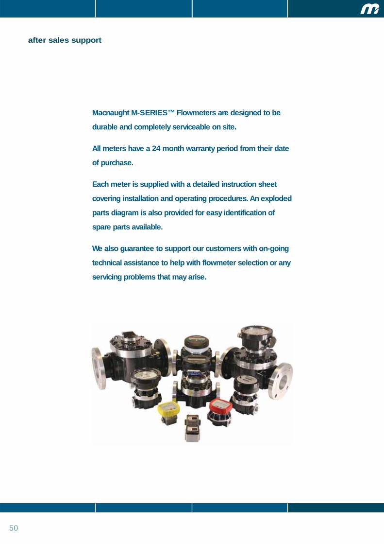
50
after sales support
Macnaught M-SERIES™ Flowmeters are designed to be
durable and completely serviceable on site.
All meters have a 24 month warranty period from their date
of purchase.
Each meter is supplied with a detailed instruction sheet
covering installation and operating procedures. An exploded
parts diagram is also provided for easy identification of
spare parts available.
We also guarantee to support our customers with on-going
technical assistance to help with flowmeter selection or any
servicing problems that may arise.

b. at the purchaser’s owncost, returning thedefective Product to thenearest authorizedMacnaught service centre.
6. Subject to compliance by thepurchaser with clause 5,Macnaught shall, at its option,repair or replace any product orcomponent found defective byits inspection by reason offaulty materials or workmanshipof Macnaught.
7. This warranty does not coverfailure of products, parts orcomponents which, in the solejudgment of Macnaught, arisesother than from faulty materialsor workmanship of Macnaught,including misuse, abrasion,corrosion, negligence, accident,substitution of non-Macnaughtparts, unauthorizedmodification, improper use,storage or handling, faultyinstallation or tampering by thepurchaser or any third party.
8. If Macnaught inspectiondiscloses no defect in materialor workmanship, repair orreplacement and return (atMacnaught’s sole option) willbe made at customary charges,which will be advised to thepurchaser.
9. Macnaught’s liability and thepurchaser’s rights under thisWarranty shall be limited torepair or replacement ofdefective products orcomponents and in particular,shall not extend to any direct,special, indirect orconsequential damage orlosses of any nature.
10. The foregoing warrantysupersedes, voids and is in lieuof all or any other warranties.
macnaught warranty
1. Macnaught Pty Ltd(“Macnaught”) warrants that allproducts manufactured byMacnaught and/or supplied byMacnaught under the“Macnaught” brand, excludingM-Series positive displacementmeters (“Meters”) andcomponents subject to wear,will be free from any defectscaused by faulty materials orworkmanship for a period of 5years from the date of purchaseof the product.
2. For Meters, the warranty periodis 12 months from the date ofpurchase of that product.
3. For components contained inall products (including Meters)which are usually subject towear from normal operation ofthe products (such as o-rings,seals, springs and hoses), thewarranty period is 12 monthsfrom the date of purchase ofthe relevant product.
4. For products and componentswhich are not manufactured byMacnaught and are supplied byMacnaught under a brand nameother than “Macnaught”, thewarranty period is the longer of12 months from date ofpurchase of the relevantproduct and the period of themanufacturer’s warranty.
5. The warranties contained inclauses 1, 2, 3 and 4 above areconditional on the Purchaser,during the relevant warrantyperiod:a. delivering to Macnaught a
detailed notice setting outfull details of any defect inany Product and details ofthe date and place ofpurchase (together withcopies of purchasereceipts and/or othersupporting documents);and
This warranty does not form part of, nor does it constitute, a contract betweenMacnaught and the end-user or purchaser. It is additional to any warranty givenby the seller of the products. This warranty does not exclude, limit, restrict ormodify the non-excludable rights or remedies conferred upon the end-user orpurchaser, or the non-excludable duties or liabilities imposed on the seller orMacnaught, by Part V, Divisions 2 and 2A of the Trade Practices Act 1974(Commonwealth) or other legislative provisions. Macnaught otherwiseexcludes, to the extent permitted by law, any rights conferred on the end-useror purchaser or duties or liabilities imposed upon Macnaught.

macnaught.com.au
Available from:
Head Office - SydneyMacnaught Pty Ltd41-49 Henderson St, TurrellaSydney NSW 2205 AustraliaPh: +61-2-9567 0401 Fax: +61-2-9597 7773 email: [email protected]: www.macnaught.com.au
Quality Endorsement applicable to Macnaught Head Office Sydney Only
Macnaught AsiaMacnaught Asia Pte Ltd20 Kallang Av. #03-00 Pico Creative Centre, Singapore, 339411Ph: +65 6396 5855 Fax: +65 6396 5871Sales Representative Office (Jakarta)Ph: +62-21-527 9015 Fax: +62-21-527 9017email: [email protected]: www.macnaught.com.au
Macnaught USAMacnaught USA, Inc.614 South Ware BoulevardDock 14A (for deliveries)Tampa, FL 33619Ph: 813-628-5506 Fax: 509-694-8495email: [email protected]: www.macnaughtusa.com
Macnaught EuropeMacnaught Europe LtdD1 Lincoln ParkBorough RoadBuckingham Road Ind EstBrackley NN13 7BEUnited KingdomPh: +44 1280 705001Fax: +44 1280 705006email: [email protected]: www.macnaughteurope.com
NA180 Issue 4 / July 2007
Airdraulics(Qld) Pty Ltd
Airdraulics (QLD) Pty Ltd • 68 Boyland Avenue • Coopers Plains • Queensland • Australia 4108
Telephone: 07 3275 3333 • Facsimile: 07 3275 2699
Web: www.airdraulics.com.au • Email: [email protected]