Macedo, R., Stamps, R. L. , and Dumelow, T. (2014) Spin ...eprints.gla.ac.uk/98736/1/98736.pdf ·...
13
n Macedo, R., Stamps, R. L., and Dumelow, T. (2014) Spin canting induced large nonreciprocal Goos-Hänchen shifts. Optics Express, 22 (23). pp. 28467-28478. ISSN 1094-4087 Copyright © 2014 Optical Society of America http://eprints.gla.ac.uk/98736/ Deposited on: 21 November 2014 Enlighten – Research publications by members of the University of Glasgow http://eprints.gla.ac.uk
-
Upload
nguyenngoc -
Category
Documents
-
view
214 -
download
1
Transcript of Macedo, R., Stamps, R. L. , and Dumelow, T. (2014) Spin ...eprints.gla.ac.uk/98736/1/98736.pdf ·...

n
Macedo, R., Stamps, R. L., and Dumelow, T. (2014) Spin canting induced large nonreciprocal Goos-Hänchen shifts. Optics Express, 22 (23). pp. 28467-28478. ISSN 1094-4087
Copyright © 2014 Optical Society of America http://eprints.gla.ac.uk/98736/ Deposited on: 21 November 2014
Enlighten – Research publications by members of the University of Glasgow
http://eprints.gla.ac.uk
Spin canting induced nonreciprocalGoos-Hanchen shifts
R. Macedo,1,∗
R. L. Stamps,1 and T. Dumelow2
1SUPA, School of Physics and Astronomy, University of Glasgow, Glasgow G12 8QQ, UK2Departamento de Fısica, Universidade do Estado do Rio Grande do Norte, Costa e Silva,
59625-620 Mossoro RN - Brazil∗[email protected]
Abstract: Recent studies on surface reflection illustrate how light beamscan be laterally shifted from the position predicted by geometrical optics,the so called Goos-Hanchen effect. In antiferromagnets this shifts can becontrolled with an external magnetic field. We show that a configuration inwhich spins cant in response to applied magnetic fields enhance possibilitiesof field controlled shifts. Moreover, we show that nonreciprocal displace-ments are possible, for both oblique and normal incidence, due to inherentnonreciprocity of the polariton phase with respect to the propagationdirection. In the absence of an external field, reciprocal displacementsoccur.
© 2014 Optical Society of America
OCIS codes: (040.2235) Far infrared or terahertz; (160.3020) Magneto-optical materials.
References and links1. R. E. Camley, “Nonreciprocal surface modes,” Surf. Sci. Rep. 7, 103–188 (1987).2. N. S. Almeida and D. L. Mills “Dynamical response of antiferromagnets in an oblique magnetic field: application
to surface magnons,” Phys. Rev. B 37, 3400 (1988).3. R. L. Stamps, B. L. Johnson, and R. E. Camley “Nonreciprocal reflection from semi-infinite antiferromagnets,”
Phys. Rev. B 43, 3626 (1991).4. K. Abraha and D. R. Tilley, “Theory of far infrared properties of magnetic surfaces, films and superlattices,”
Surf. Sci. Rep. 24, 129 (1996).5. T. Dumelow and R. E. Camley, “Nonreciprocal reflection of infrared radiation from structures with antiferromag-
nets and dielectrics,” Phys. Rev. B 54, 12232 (1996).6. T. Dumelow, R. E. Camley, K. Abraha, and D. R. Tilley, “Nonreciprocal phase behavior in reflection of electro-
magnetic waves from magnetic materials,” Phys. Rev. B 58, 897 (1998).7. L. Remer, B. Luthi, H. Sauer, R. Geick, and R. E. Camley, “Nonreciprocal optical reflection of the uniaxial
antiferromagnet MnF2,” Phys. Rev. Lett. . 56, 2752 (1986).8. D. E. Brown, T. Dumelow, T. J. Parker, K. Abraha, and D. R. Tilley, “Nonreciprocal reflection by magnons in
FeF2: a high resolution study,” Phys. Rev. B 49, 12266 (1994).9. K. Abraha, D. E. Brown, T. Dumelow, T. J. Parker, and D. R. Tilley, “Oblique incidence far-infrared reflectivity
study of the uniaxial antiferromagnet FeF2,” Phys. Rev. B 50, 6808 (1994).10. M. R. F. Jensen, T. J. Parker, Kamsul Abraha, and D. R. Tilley “Experimental observation of magnetic surface
polaritons in FeF2 by attenuated total reflection’,’ Phys. Rev. Lett. 75, 3756 (1995).11. T. Dumelow, J. A. P. da Costa, F. Lima, and E. L. Albuquerque. “Nonreciprocal phenomena on reflec-
tion of terahertz radiation off antiferromagnets,” in Recent Optical and Photonic Technologies, Ki YoungKim (Ed.), (InTech, Vukovar, 2010), Chap. 8. http://www.intechopen.com/books/recent-optical-and-photonic-technologies/nonreciprocal-phenomena-on-reflection-of-terahertz-radiation-off-antiferromagnets.
12. F. Lima, T. Dumelow, E. L. Albuquerque, and J. A. P. da Costa, “Nonreciprocity in the Goos–Hanchen shift onoblique incidence reflection off antiferromagnets,” J. Opt. Soc. Am. B 28, 306–313 (2011).
13. F. Goos and H. Hanchen, “Ein neuer und fundamentaler Versuch zur Totalreflexion,” Ann. Phys. 436(7-8), 33–46(1947).
#222383 - $15.00 USD Received 3 Sep 2014; revised 10 Oct 2014; accepted 10 Oct 2014; published 7 Nov 2014(C) 2014 OSA 17 November 2014 | Vol. 22, No. 23 | DOI:10.1364/OE.22.028467 | OPTICS EXPRESS 28467

14. H. K. V. Lotsch, “Beam displacement at total reflection: the Goos-Hanchen effect,” Optik 32, 116,189,299,553(1970).
15. Miri, A. Naqavi, A. Khavasi, K. Mehrany, S. Khorasani, and B. Rashidian, “Geometrical approach in physicalunderstanding of the Goos-Haenchen shift in one- and two-dimensional periodic structures,” Opt. Lett. 33 2940–2942 (2008).
16. T. Tamir and H. L. Bertoni, “Lateral displacement of optical beams at multilayered and periodic structures,” J.Opt. Soc. Am. 61, 1397–1413 (1971).
17. Y. Huang, B. Zhao, and L. Gao, “Goos-Hanchen shift of the reflected wave through an anisotropic metamaterialcontaining metal/dielectric nanocomposites,” J. Opt. Soc. Am. 29 1436–1444 (2012)
18. X. -Q Jiang, Z. W Lu, and X. -D Sun, “Control of direction of Goos-Hanchen shift on reflection from a weaklyabsorbing medium,” Optik 122, 2140–2142 (2011).
19. B. Zhao and L. Gao, “Temperature-dependent Goos-Hanchen shift on the interface of metal/dielectric compos-ites,” Opt. Express 17, 21433–21441 (2009).
20. D. Gao and L. Gao, “Goos-Hanchen shift of the reflection from nonlinear nanocomposites with electric fieldtunability,” Appl. Phys. Lett. 97, 041903 (2010).
21. W. J. Wild and C. L. Giles, “Goos-Hanchen shifts from absorbing media,” Phys. Rev. A 25, 2099 (1982).22. P. T Leung, Z.W Chen, and H. -P Chiang, “Large negative Goos-Hanchen shift at metal surfaces,” Opt. Commun.
276, 206–208 (2007) .23. M. Merano, A. Aiello, G. W ’t Hooft, M. P van Exter,E. R Eliel, and J. P Woerdman, “Observation of Goos-
Hanchen shifts in metallic reflection,” Opt. Express 15, 15928–15934 (2007).24. R. Macedo and T. Dumelow, “Beam shifts on reflection of electromagnetic radiation off anisotropic crystals at
optic phonon frequencies,” Journal of Optics 15, 014013 (2013).25. F. Lima, T. Dumelow, J. A. P. da Costa, and E. L. Albuquerque, “Lateral shift on normal incidence reflection off
an antiferromagnet,” Europhys. Lett. 83, 17003 (2008).26. F. Lima, T. Dumelow, J. A. P. da Costa, and E. L. Albuquerque, “Power flow associated with the Goos-Hanchen
shift of a normally incident electromagnetic beam reflected off an antiferromagnet,” Phys. Rev. B 79 155124(2009).
27. D. L. Mills and E. Burstein, “Polaritons: the electromagnetic modes of media,” Rep. Prog. Phys. 37, 817 (1974).28. M. McGuirk and C. K. Carniglia, “An angular spectrum approach to the Goos-Hanchen shift,” J. Opt. Soc. Am.
. 67, 103–107 (1977).29. K. Artmann “Berechnung der seitenversetzung des totalrelektierten strahles,” Ann. Phys. 437, 87–102 (1948).30. T. Dumelow and M. C. Oliveros, “Continuum model of confined magnon polaritons in superlattices of antiferro-
magnets,” Phys. Rev. B 55, 994 (1997).31. R. Macedo and T. Dumelow, “Tunable all-angle negative refraction using antiferromagnets,” Phys. Rev. B 89,
035135 (2014).32. R. Macedo R. Rodrigues da Silva, T. Dumelow, and J. A. P. da Costa, “MgF2 as a material exhibiting all-angle
negative refraction and subwavelength imaging due to the phonon response in the far infrared,” Opt. Commun.310 94–99 (2014).
1. Introduction
Nonreciprocity has been extensively studied for antiferromagnetic structures in the presenceof an external field B0. Effects have been shown theoretically [1–6] and experimentally [7–10], one of the most important being that associated with optical reflection. Nonreciprocity ofreflection implies that the properties of the reflected beam for an angle of incidence +θ1 differfrom those for an angle of incidence −θ1. Affected properties include the intensity [5, 7–9, 11]and phase [6] of the reflected beam, which can change or enhance optical effects.
The nonreciprocal Goos-Hanchen shift on reflection from antiferromagnets is a particularlyinteresting effect [12]. The Goos-Hanchen effect can be considered as a lateral displacementof a reflected beam at a boundary between two different media. This concept was first investi-gated experimentally by Goos and Hanchen [13, 14], even though Isaac Newton had predictedsuch a shift in the reflected beam centuries earlier. There are several studies of such a shifton the external reflection from materials such as photonic crystals [15], multilayered struc-tures [16], metal-dielectric nanocomposites [17], and weakly absorbing media [18]. Tunabilityof the Goos-Hanchen shift has been explored in terms of temperature [19] and applied electricfield [20] dependence in the case of reflection from metal-dielectric composites. In the case ofreflection from naturally occurring materials, there exist Goos-Hanchen shifts associated with
#222383 - $15.00 USD Received 3 Sep 2014; revised 10 Oct 2014; accepted 10 Oct 2014; published 7 Nov 2014(C) 2014 OSA 17 November 2014 | Vol. 22, No. 23 | DOI:10.1364/OE.22.028467 | OPTICS EXPRESS 28468

the plasma response in metals [21–23] and the far infrared phonon response in crystals such asquartz [24].
In the case of the Goos-Hanchen shift associated with reflection from antiferromagnets, theeffect stems from the fact that, at terahertz frequencies, the magnetic component of electro-magnetic radiation can interact with the spin precession near magnon-polariton resonances.The resulting shift may become nonreciprocal in the presence of an suitably applied externalfield B0. Up to now, studies of Goos-Hanchen shifts in reflection from antiferromagnets haveconsidered only the situation where B0 is applied along the anisotropy axis, perpendicular tothe plane of incidence [12,25,26]. In the present work we consider an antiferromagnet in an al-ternative configuration in which, in the absence of an external field, coupling to the precessingspins only occurs at oblique incidence, leading to narrow reststrahl regions. We consider theresulting Goos-Hanchen shifts in this case, and study the effect of applying an external mag-netic field perpendicular to the spin alignment direction, causing the spins to cant. Due to thiscanting, the resonance frequency is shifted to higher frequencies, and the beam displacementbecomes nonreciprocal. Spin canting also leads to displacements at normal incidence.
The paper is organized as follows. Section 2 presents a theoretical background in whichthe antiferromagnet crystal geometry is presented and reflection from the antiferromagneticsurface is analyzed. Section 3 presents the study of the Goos-Hanchen shifts in the absence ofa magnetic field. In Section 4 we consider the effects of an external field B0 on the reflectionfrom an antiferromagnet at oblique and normal incidence. Conclusions are given in Section 5.
2. Theoretical background
We are interested in the Goos-Hanchen shift for reflection at the boundary between vacuum anda semi-infinite antiferromagnetic crystal as aligned in the coordinate system depicted in Fig. 1.The crystal’s easy axis is oriented along x, parallel to the surface, and the incidence plane is xz.We also allow for a static field B0 applied along the y direction, perpendicular to the anisotropyaxis.
Si
�1
Sr
Dx
z
B0
y
Fig. 1. Schematic representation of an oblique incident beam with an angle θ1 being dis-placed on the reflection by a distance D at the interface between vacuum and an antiferro-magnet, where Si and Sr are the incident and reflected Poynting vector respectively.
2.1. Plane wave reflection from the antiferromagnet
We consider the situation where a field applied along y cants the spins at an angle α in theplane xy calculated in terms of BA (magnitude of the anisotropy field) and an exchange field BE
(acting between the spin sublattices). The angle α is then given by
sinα =B0
BA +2BE. (1)
#222383 - $15.00 USD Received 3 Sep 2014; revised 10 Oct 2014; accepted 10 Oct 2014; published 7 Nov 2014(C) 2014 OSA 17 November 2014 | Vol. 22, No. 23 | DOI:10.1364/OE.22.028467 | OPTICS EXPRESS 28469

One can show that the antiferromagnetic resonance frequency is [2, 4]
ω⊥ = (ω2r cos2 α +2γ2B0 sinα)1/2. (2)
where ωr = γ(2BABE +B2A)
1/2 and γ is the gyromagnetic ratio. In our geometry the permeabilitytensor μ takes the form
μ =
⎛⎝
μxx 0 μxz
0 μyy 0−μxz 0 μzz
⎞⎠ . (3)
We consider only s-polarized radiation (E-field along y, perpendicular to the plane of inci-dence). In this case, the relevant components are [2]
μxx = 1+2μ0γ2MSB0 sinαω2⊥− (ω + iΓ)2
, (4)
μzz = 1+2μ0γ2MS(B0 sinα +BA cos2α)
ω2⊥− (ω + iΓ)2
, (5)
and
μxz =−μxz =−i2μ0γ2MS(ω + iΓ)sinα
ω2⊥− (ω + iΓ)2
. (6)
The complex reflection coefficient r for reflection from an antiferromagnet in the presentgeometry is
r =kz1(μxxμzz +μ2
xz)− kz2μzz − kxμxz
kz1(μxxμzz +μ2xz)+ kz2μzz + kxμxz
. (7)
Here the parallel wavevector component kx of a plane wave will be given by kx = k0 sinθ1,where θ1 is the angle of incidence and k0 = ω/c. The wavevector components kz1 (in vacuum)and kz2 (in the antiferromagnet) are given by
k2z1 = k2
0 − k2x (8)
and
k2z2 =
εk20(μxxμzz +μ2
xz)− k2x μxx
μzz(9)
respectively, where ε represents the dielectric constant of the antiferromagnet.
2.2. Goos-Hanchen shift on reflection of a finite beam
In the case of reflection of a finite beam, we can still base our analysis on plane wave reflectionby considering such a beam as a sum of plane waves. Such a plane wave spectrum approachhas been usefully applied to analyzing Goos-Hanchen shifts by McGuirk and Carniglia [28].Here we summarize the resulting theory for application to the present case.
In this approach, we consider the electric field (directed along y) associated with the incidentbeam as a Fourier sum of plane waves in the form
Ei(x,z) =∫ k0
−k0
ψ(kx)ei(kxx+k1zz) dkx, (10)
#222383 - $15.00 USD Received 3 Sep 2014; revised 10 Oct 2014; accepted 10 Oct 2014; published 7 Nov 2014(C) 2014 OSA 17 November 2014 | Vol. 22, No. 23 | DOI:10.1364/OE.22.028467 | OPTICS EXPRESS 28470

where kx is the in-plane component of the wavevector associated with a particular plane waveand ψ(kx) is a distribution function representing the shape of the beam. The electric field dis-tribution the incident beam at the surface, which we define to be at z = 0, ia given by
Ei(x,0) =∫ +k0
−k0
ψ(kx)ekxx dkx, (11)
and the electric field distribution of the corresponding reflected beam at the surface is
Er(x,0) =∫ +k0
−k0
r(kx)ψ(kx)eikxx dkx. (12)
r(kx) represents the complex reflection coefficient, which we can represent as
r(kx) = ρ(kx)eiφ(kx), (13)
where ρ(kx) is the reflection amplitude and φ(kx) is the associated phase change on reflection.If this phase change varies with kx, interference between the reflected plane waves will bedifferent from that for the incident waves, leading to a change in the reflected beam profile.This typically manifests itself as a lateral shift of the reflected beam [26,28,29] associated withderivative of φ(kx). To see this, consider a wide beam. In this case, kx assumes a narrow range ofvalues centered around kx = kx0, where kx0 = k0 sinθ1, the angle θ1 being the effective incidentangle of the overall beam. If we now expand ρ and φ as a Taylor series around kx = kx0, Eq.(12) can be approximated to
Er(x) = r(kx0)∫ +k0
−k0
ψ(kx)exp
[kx
(x+
dφdkx
∣∣∣∣kx=kx0
)]dkx, (14)
where r(kx0) is the reflection coefficient of a plane wave whose angle of incidence is θ1. Theintegral representing the profile of the reflected beam in Eq. (14) is the same as that for theincident beam in Eq. (11) except that x has been replaced by x+D. Thus the reflected beamhas, in effect, been shifted along the surface by a distance D, given by
D =− dφdkx
∣∣∣∣kx=kx0
. (15)
3. Zero field Goos-Hanchen shifts
We now apply our theory to reflection of s-polarized radiation obliquely incident at avacuum/MnF2 interface. MnF2 is a well characterized antiferromagnet that can be readily pre-pared and studied experimentally. For this material, the relevant parameters [30] at a tempera-ture of 4.2 K are MS = 6.0× 10⁵ A/m and BA = 0.787T. The Neel temperature is 67 K andthe corresponding exchange field is BE = 53.0 T. Also γ/2πc = 0.975 cm−1/T, correspondingto ωr/2πc = 8.94 cm−1. The damping parameter is Γ/2πc = 0.0007 cm−1 and the dielectricconstant is ε = 5.5. If B0 = 0, μzz has a pole at the resonance frequency 8.94 cm−1 and a zeroat a somewhat higher frequency close to 9.00 cm−1.
As a first approach we take B0 = 0. The permeability tensor is then diagonal and r reducesto
r =(μxxkz1 − kz2)
(μxxkz1 + kz2), (16)
withk2
z2 = εμxxk20 −
μxx
μzzk2
x . (17)
#222383 - $15.00 USD Received 3 Sep 2014; revised 10 Oct 2014; accepted 10 Oct 2014; published 7 Nov 2014(C) 2014 OSA 17 November 2014 | Vol. 22, No. 23 | DOI:10.1364/OE.22.028467 | OPTICS EXPRESS 28471

In Fig. 2(a) we present the calculated plane wave reflectance R = rr∗ spectra, obtained usingEq. (16), for incident angles of ±60◦. Results with and without damping Γ are shown. In eachcase, there is no difference between the θ1 = +60◦ and the θ1 = −60◦ reflectivity, i.e. thereflectivity is reciprocal R(θ1) = R(−θ1). This is expected from simple symmetry arguments[1].
9.029.019.008.990.0
0.5
1.0
0.0
0.5
1.0
-0.4
0.0
0.4
0
-�
1.00.50.0-1.0 -0.5
D (
cm)
R
�
(a)
(b) (d)
(c)
Fig. 2. (a) Calculations of s-polarized oblique incidence (θ1 = ±60◦) reflection from theinterface between vacuum and MnF2 and (b) Goos-Hanchen shift D. Reflected (c) phaseand (d) amplitude, as a function of in-plane wavevector kx, at the frequency marked as Ain (a) (9.0103 cm−1) for the configuration shown in Fig. 1. Dashed lines are calculatedfor Γ = 0, whereas solid lines are for calculations in which Γ = 0.0007 cm−1. The shadedregions show where transmission is possible in the absence of damping. In case (a) thecurves corresponding to θ1 =±60◦ are coincident, so only a blue curve is seen in the caseof the solid lines. Note that, in part (c), φ = π is represented as φ =−π in the Γ = 0 curvefor consistency with the Γ = 0.0007 cm−1 curve.
In the case when Γ = 0, kz2 is either wholly real or imaginary. In the case of kz2 real,propagation through the antiferromagnet can occur. These regions are indicated by shadingin the figures. In the case of kz2 imaginary, reflection is total, with no propagation into theantiferromagnet. These are reststrahlen regions. For μxx positive, the reststrahlen condition is0 < μzz < (1/ε)sin2 θ1 which, providing θ1 �= 0, is satisfied in a narrow frequency region [31]just above the zero in μzz. In the configuration considered here, the reststrahlen region onlyexists at oblique incidence, and its width depends on the angle of incidence. In Fig. 2(a) it isseen that, in the zero damping case (dashed lines), the reflectivity is unity within this region andsmaller elsewhere.
In Fig. 2(b) we show the Goos-Hanchen shifts calculated according to Eq. (15). In a similarmanner to the result seen for reflectivity, these shifts are found to be reciprocal, which in thiscase corresponds to the relation D(+θ1) =−D(−θ1). In the absence of damping, the shifts arenonzero only in the reststrahlen region. This is similar to the behavior of Goos-Hanchen shiftsassociated with the phonon response in dielectric crystals [32], and can be explained by thefact that in the propagation regions the phase is either 0 or π (i.e. r is wholly real) but in thereststrahlen regions it takes on other values.
Since the displacement D depends on the derivative of the reflected phase (Eq. (15)), it isuseful to plot φ and ρ as functions of kx. In Fig. 2(c) we show φ(kx) at the frequency marked asA in Fig. 2(a) (9.0103 cm−1), and in Fig. 2(d) we show the corresponding amplitude values ρ ,highlighting the values of kx corresponding to θ1 =±60◦. In the absence of damping, there areimportant differences between the behavior for k2
x/k20 < εμzz (i.e. sin2 θ1 < εμzz) and k2
x/k20 >
#222383 - $15.00 USD Received 3 Sep 2014; revised 10 Oct 2014; accepted 10 Oct 2014; published 7 Nov 2014(C) 2014 OSA 17 November 2014 | Vol. 22, No. 23 | DOI:10.1364/OE.22.028467 | OPTICS EXPRESS 28472

εμzz. In the former case, corresponding to propagation regions, the amplitude ρ is less than1 and the phase φ is constant at 0 or π , so that there is no displacement. In the latter case,corresponding to reststrahlen region behavior, the amplitude is unity, corresponding to totalreflection, and the phase is continuously varying, leading to nonzero displacement. θ1 = ± 60◦corresponds to reststrahlen behavior, resulting in the nonzero shift seen in Fig. 2 at frequencyA. In the presence of damping, the phase in the bulk region is no longer strictly constant, so aGoos-Hanchen shift is also possible for lower angles of incidence, albeit most markedly in lowreflectivity regions.
The lateral displacement of a Gaussian beam obliquely incident on a MnF2 surface is shownin Fig. 3. In this case the beam is given by Eq. (10) with [26, 31, 32]
ψ(kx) =− g
2cosθ1√
πexp
[−g2(kx − kx0)
2
4cos2 θ1
], (18)
where 2g represents the beam width at the sample surface and θ1 is the incident angle.We take g ≈ 2λ , where λ is the free space wavelength of the radiation. The results in Fig.
3 are for the same frequency as that used in Figs. 2(c) and 2(d), i..e Frequency A (9.0103cm−1). At this frequency the reflectivity is large even when damping is included. We clearlysee that the incident beam is positively shifted with a large displacement of around D = 0.2 cm(approximately 2λ ), in line with the results predicted from Fig. 2(b).
Fig. 3. Calculated overall power intensity (in terms of the magnitude of the time-averagedPoynting vector) showing intensities for a beam of width g = 0.2 cm obliquely incident(θ1 = +60◦) on a vacuum/MnF2 interface at the frequency marked as A in Fig. 2 (9.0103cm−1). The arrows represent the incident and reflected beams, positioned according to Eq.(15), with angle of reflection assumed equal to angle of incidence.
4. Tunable shifts with B0 �= 0
Without an external magnetic field the effects associated with external reflection from an an-tiferromagnetic surface are reciprocal. When a field is applied, nonreciprocal effects, eitherconsidered with respect to reversing the sign of the incident angle or that of the applied field,are introduced.
#222383 - $15.00 USD Received 3 Sep 2014; revised 10 Oct 2014; accepted 10 Oct 2014; published 7 Nov 2014(C) 2014 OSA 17 November 2014 | Vol. 22, No. 23 | DOI:10.1364/OE.22.028467 | OPTICS EXPRESS 28473

The nonreciprocal behavior considered here is associated with the off-diagonal elements μxz
and μzx of the permeability tensor. They are nonzero only due to the canting of the spins, whichresults in a small spin component along the applied field direction.
For the geometry shown in Fig. 1, spin precession is mainly restricted to the yz plane, withthe spins on the two sublattices precessing in opposite directions. However, when the spins arecanted toward the y axis, one can consider that there is also a small amount of precession inthe xz plane. In this plane, the precession direction is the same for both sublattices, but changesdirection when the field direction is reversed. The antiferromagnet is thus gyromagnetic, withnonzero permeability components μxz and μzx whose signs depend on the field direction. Ifthe incident field of the electromagnetic radiation has a magnetic component in the xz plane,therefore, nonreciprocal effects, such as nonreciprocal Goos-Hanchen shifts, may be expectedin reflection.
Nonzero μxz and μzx values are also responsible for the nonreciprocal Goos-Hanchen shiftsin the previously studied configuration in which the easy axis is taken parallel to the appliedfield, along y [12, 25, 26]. In such a configuration, however, they become nonzero without thenecessity of spin canting. Noticeably higher fields are therefore necessary in the present casethan in the previously studied one.
In Fig. 4 we show the effect on the Goos Hanchen shifts of applying an external field. Thefigure shows how the applied field shifts the resonance to higher frequencies and how the dis-placement becomes nonreciprocal D(+θ1) �=−D(−θ1). The effect of the field on the displace-ment is distinctly nonlinear, and this appears to be associated with coupling of the incidentradiation to surface resonances. In this paper we concentrate on the specific case of B0 = 1.5 T.
9.159.109.059.00
-1.0
0.0
1.0
-1.0
0.0
1.0
-1.0
0.0
1.0
-1.0
0.0
1.0
D (
cm)
(d)
(c)
(b)
(a)
Fig. 4. Goos-Hanchen shift D for different values of applied external field (a) B0 = 0.0 T,(b) B0 = 0.5 T, (c) B0 = 1.0 T and (d) B0 = 1.5 T. Blue lines are calculated for θ1 =+600,whereas red lines are calculated for θ1 =−600
#222383 - $15.00 USD Received 3 Sep 2014; revised 10 Oct 2014; accepted 10 Oct 2014; published 7 Nov 2014(C) 2014 OSA 17 November 2014 | Vol. 22, No. 23 | DOI:10.1364/OE.22.028467 | OPTICS EXPRESS 28474

4.1. Oblique incidence
In Fig. 5(a) we show the reflectivity R for oblique incidence (θ1 = ±600) reflection from anMnF2 surface with an external magnetic field B0 = 1.5 T. All features are now at higher fre-quencies than in Fig. 2 due to the higher resonance frequency ω⊥ (Eq. (2)). In the case of Γ = 0(dashed lines), both positive and negative angles of incidence give the same result. However,when Γ �= 0, R(+θ1) and R(−θ1) are no longer identical. This is an example of the well-knownresult that the reflectivity is reciprocal in the absence of damping but can be nonreciprocal whendamping is present [1, 3, 7, 8].
9.149.139.129.110.0
0.5
1.0
0.0
0.5
1.0
-0.6
0.0
0.6
0
-�
1.00.50.0-1.0 -0.5
D (
cm)
R
�
(d)
(c)(a)
(b)
�
Fig. 5. (a) Calculations of s-polarized oblique incidence (θ1 = ±60◦) reflection from theinterface between vacuum and MnF2 in the presence of an external magnetic field of 1.5 Tand (b) Goos-Hanchen shift D. Reflected (c) phase and (d) amplitude, as a function ofin-plane wavevector kx, at frequency marked as B (9.125 cm−1) in (a). Dashed lines arecalculated ignoring damping, whereas solid lines are for calculations in which dampingis included. The shaded region shows frequencies where transmission can occur in theabsence of damping.
In Fig. 5(b) we show the corresponding Goos-Hanchen shifts. It is immediately seen thatthe shifts are distinctly nonreciprocal D(+θ1) �= −D(−θ1), either with or without damping.Furthermore, there are nonreciprocal shifts some way into the propagation region. Indeed, inthe absence of damping, we observe the somewhat counterintuitive property D(+θ1) =D(−θ1)in this region. Alternatively one could say that, for some given incident angle, reversing the fielddirection would change the sign of D without changing its amplitude. This result has also beenshown for the case of the easy axis perpendicular to the plane of incidence [12].
In Fig. 5(c) we show the reflected phase φ as a function of kx at the frequency marked as Bin Fig. 5(a) (9.125 cm−1). In 5(d) we show the corresponding amplitude ρ . The nonreciprocalphase behavior is similar to that discussed by Dumelow et. al. [6], and leads to nonreciprocalGoos-Hanchen shifts. For smaller incident angles, corresponding to transmission region behav-ior (−0.6 < kx/k0 < 0.6), the amplitude is less than unity in the absence of damping, as in thezero field case. However, the phase is no longer simply 0 or π in this region. It is in fact anti-symmetric about kx = 0, so that φ(kx) =−φ(−kx). This can be shown by resolving Eq. (7) intoreal and imaginary terms (recalling that μxz is imaginary in the absence of damping, all otherterms being real), and leads to equal derivatives for positive and negative kx, giving the resultdiscussed above (D(+θ1) = D(−θ1)) for the transmission region frequencies.
For the situation shown in Fig. 5 we are interested in the phase derivative at θ1 = ±60◦(shown as red arrows in Fig. 5(c)). This corresponds to reststrahlen behavior, as anticipatedfrom Fig. 5. dφ/dkx is clearly nonzero and its magnitude is different for positive and negative
#222383 - $15.00 USD Received 3 Sep 2014; revised 10 Oct 2014; accepted 10 Oct 2014; published 7 Nov 2014(C) 2014 OSA 17 November 2014 | Vol. 22, No. 23 | DOI:10.1364/OE.22.028467 | OPTICS EXPRESS 28475

angles, in agreement with Fig. 5(b), in which nonreciprocity in the Goos-Hanchen shift can beseen. In the absence of damping the amplitude values ρ for positive and negative values of kx
are exactly the same, confirming the results already discussed in relation to Fig. 5(b).Using the plane wave spectrum model represented by Eqs. (10) and (18), we can simulate
a Gaussian beam reflected from an antiferromagnet specimen (as in Fig. 3) in the presence ofa nonzero external magnetic field. In the present case we are using the same conditions as inFig. 5(c). In Fig. 6(a), we show results for a positive incident angle θ1 =+60◦, correspondingto a small displacement of approximately +0.03 cm, as expected from Fig. 5(b). In Fig. 6(b)we show the case for θ1 = −60◦. In this case we can observe a displacement of about -0.1 cm(i.e., D � −λ ), which also agrees with the results shown in Fig. 5(b). Thus, although the signof the displacement has changed, as expected, the amplitude is considerably larger than in theθ1 =+60◦ case, confirming that the Goos-Hanchen shift is nonreciprocal.
Fig. 6. Calculated overall power intensity (in terms of the magnitude of the time-averagedPoynting vector) showing intensities for a beam of width g = 0.2 cm obliquely incident ona vacuum/MnF2 interface at frequency B (ω = 9.125 cm−1) in the presence of a magneticfield B0 = 1.5 T. (a) θ1 = +60◦; (b) θ1 = −60◦ .The arrows represent the incident andreflected beams, positioned according to Eq. (15), with angle of reflection assumed equalto angle of incidence.
4.2. Normal incidence
We now consider the possibility of a normal incidence Goos-Hanchen shift of the type discussedby Lima et. al. [25,26] for the case of the antiferromagnet easy axis parallel to the applied field.In the absence of an external field, the reflected phase is reciprocal [i.e., φ(+kx) = φ(−kx)], sodφ/dkx will be zero at normal incidence (kx = 0), resulting in a zero shift. In fact, as discussedin Section II, there is no reststrahlen region associated with normally incident radiation, and nomagnon-polariton related phenomena are expected. In the presence of a nonzero external field,however, due to the more complex nature of the permeability tensor represented by Eq. (3), anarrow reststrahlen region does appear at normal incidence. This can be seen from Fig. 7(a),which shows the normal incidence reflectivity in the presence of a an applied field of 1.5 T,i.e., the same configuration as in the Fig. 5 but at normal incidence. We can see that there is anarrow reststrahlen region, centered around 9.12 cm−1. In this region, the reflectivity is unityin the absence of damping, although it is considerably less in the presence of damping.
Figure 7(b) shows the normal incidence Goos-Hanchen shift, which is nonzero both insideand outside the reststrahl region. At frequency B, in the bulk region, there is small negative
#222383 - $15.00 USD Received 3 Sep 2014; revised 10 Oct 2014; accepted 10 Oct 2014; published 7 Nov 2014(C) 2014 OSA 17 November 2014 | Vol. 22, No. 23 | DOI:10.1364/OE.22.028467 | OPTICS EXPRESS 28476
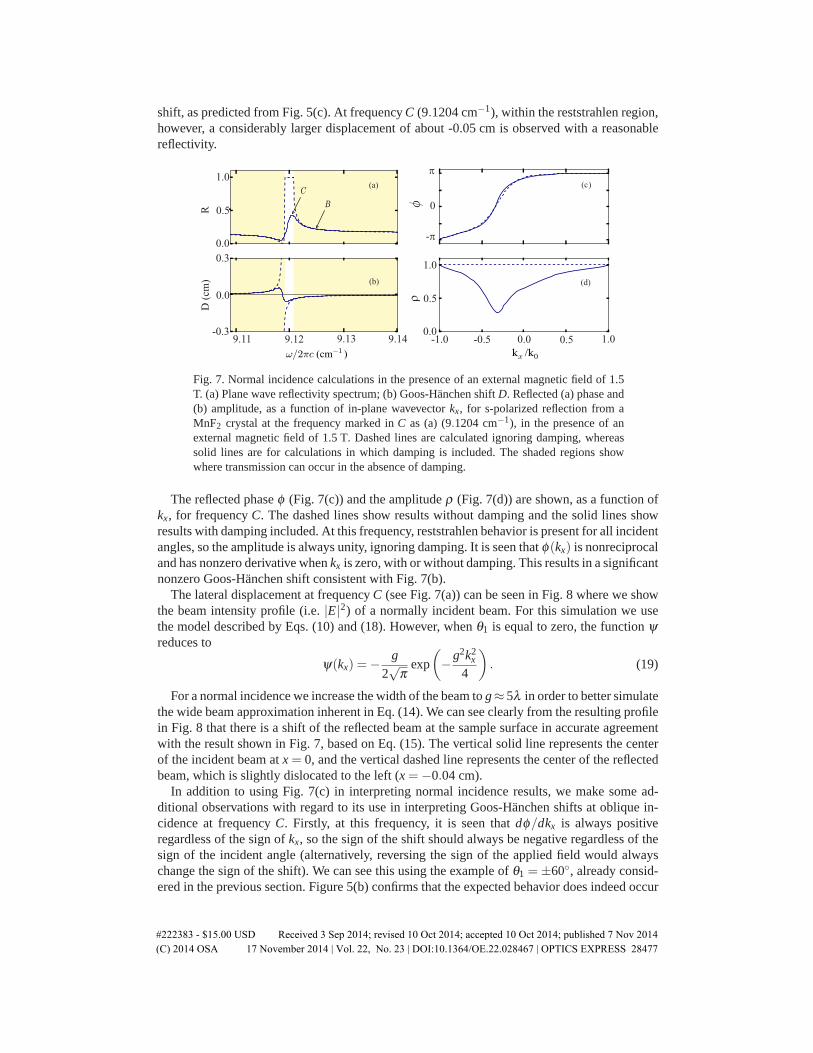
shift, as predicted from Fig. 5(c). At frequency C (9.1204 cm−1), within the reststrahlen region,however, a considerably larger displacement of about -0.05 cm is observed with a reasonablereflectivity.
9.149.139.129.110.0
0.5
1.0
0.0
0.5
1.0
-0.3
0.0
0.3
0
-�
1.00.50.0-1.0 -0.5
D (
cm)
R
�
(d)
(c)(a)
(b)
�
Fig. 7. Normal incidence calculations in the presence of an external magnetic field of 1.5T. (a) Plane wave reflectivity spectrum; (b) Goos-Hanchen shift D. Reflected (a) phase and(b) amplitude, as a function of in-plane wavevector kx, for s-polarized reflection from aMnF2 crystal at the frequency marked in C as (a) (9.1204 cm−1), in the presence of anexternal magnetic field of 1.5 T. Dashed lines are calculated ignoring damping, whereassolid lines are for calculations in which damping is included. The shaded regions showwhere transmission can occur in the absence of damping.
The reflected phase φ (Fig. 7(c)) and the amplitude ρ (Fig. 7(d)) are shown, as a function ofkx, for frequency C. The dashed lines show results without damping and the solid lines showresults with damping included. At this frequency, reststrahlen behavior is present for all incidentangles, so the amplitude is always unity, ignoring damping. It is seen that φ(kx) is nonreciprocaland has nonzero derivative when kx is zero, with or without damping. This results in a significantnonzero Goos-Hanchen shift consistent with Fig. 7(b).
The lateral displacement at frequency C (see Fig. 7(a)) can be seen in Fig. 8 where we showthe beam intensity profile (i.e. |E|2) of a normally incident beam. For this simulation we usethe model described by Eqs. (10) and (18). However, when θ1 is equal to zero, the function ψreduces to
ψ(kx) =− g
2√
πexp
(−g2k2
x
4
). (19)
For a normal incidence we increase the width of the beam to g≈ 5λ in order to better simulatethe wide beam approximation inherent in Eq. (14). We can see clearly from the resulting profilein Fig. 8 that there is a shift of the reflected beam at the sample surface in accurate agreementwith the result shown in Fig. 7, based on Eq. (15). The vertical solid line represents the centerof the incident beam at x = 0, and the vertical dashed line represents the center of the reflectedbeam, which is slightly dislocated to the left (x =−0.04 cm).
In addition to using Fig. 7(c) in interpreting normal incidence results, we make some ad-ditional observations with regard to its use in interpreting Goos-Hanchen shifts at oblique in-cidence at frequency C. Firstly, at this frequency, it is seen that dφ/dkx is always positiveregardless of the sign of kx, so the sign of the shift should always be negative regardless of thesign of the incident angle (alternatively, reversing the sign of the applied field would alwayschange the sign of the shift). We can see this using the example of θ1 =±60◦, already consid-ered in the previous section. Figure 5(b) confirms that the expected behavior does indeed occur
#222383 - $15.00 USD Received 3 Sep 2014; revised 10 Oct 2014; accepted 10 Oct 2014; published 7 Nov 2014(C) 2014 OSA 17 November 2014 | Vol. 22, No. 23 | DOI:10.1364/OE.22.028467 | OPTICS EXPRESS 28477

-0.60.0
0.5
1.0
-0.3 0.60.30.0x (cm)
Fig. 8. Intensity profiles of the incident (solid curve) and reflected (dashed curve) gaussianbeam of width g = 0.5 cm, at the frequency marked as C as Fig. 7 (9.1204 cm−1), normallyincident on MnF2 in the presence of a magnetic field B0 = 1.5 T, with damping effects takeninto account. The vertical solid line represents the center of the incident beam (x = 0) andthe vertical dashed line represents the center of the reflected beam (x =−0.04 cm).
at frequency C. For θ1 = +60◦, there is a very small negative displacement, reflecting the factthat the derivative of φ(kx) is small and positive. For θ1 = −60◦, there is a somewhat largernegative displacement, as predicted from the derivative of the φ(kx) curve in Fig.7(a).
A second observation with regard to this figure concerns a comparison of the phase behaviorin Fig. 7(c) with the amplitude behavior in Fig. 7(d). As can be seen, the amplitude turns out tobe extremely nonreciprocal when damping effects are included. In fact it reaches a minimumwithin the negative kx regime where the phase has a large derivative, i.e. where the shift Dwill be large. When this occurs, both kx and D are negative, i.e., they are both in the samedirection, resulting in what would normally be described as a positive Goos-Hanchen shift.This implies an increased penetration into the antiferromagnet, so it is reasonable to expecta higher absorption. In the case of a negative Goos-Hanchen shift (positive kx) there is lesspenetration, and hence less absorption [12].
5. Conclusions
We have considered the reflection of terahertz radiation from an uniaxial antiferromagneticcrystal (MnF2) with its uniaxis in the plane of incidence, parallel to the antiferromagnet sur-face. We find that large Goos-Hanchen shifts (D ≈ 0.2 cm ) for external reflections from anantiferromagnetic crystal are possible. Using an s-polarized terahertz beam, we show that, inthe absence of an external magnetic field, these shifts are reciprocal (D(+θ1) =−D(−θ1)) andonly occur in the reststrahlen regions. These reststrahlen regions only exist at oblique incidenceand are much narrower than when the spins are perpendicular to the plane of incidence (thecase studied by Lima et. al. [12]).
We have shown that a magnetic field B0 externally applied perpendicular to the uniaxis caninduce nonreciprocity. This nonreciprocity is associated with a spin component parallel to theapplied field. This particular spin component only exists due to canting of the spins, and forthis effect to be evident somewhat higher fields than in the previously studied case, in whichthe uniaxis is parallel to the field, are necessary. The magnitude of non-reciprocal effects islargely associated with coupling of the incident radiation to surface resonances, and this aspectdeserves further study.
Acknowledgments
The authors have benefited from useful discussions with Scott G. Smith. This work was sup-ported by the Engineering and Physical Sciences Research Council (EPSRC grant numberEP./L002922/1), the Brazilian Agency CNPq and the University of Glasgow.
#222383 - $15.00 USD Received 3 Sep 2014; revised 10 Oct 2014; accepted 10 Oct 2014; published 7 Nov 2014(C) 2014 OSA 17 November 2014 | Vol. 22, No. 23 | DOI:10.1364/OE.22.028467 | OPTICS EXPRESS 28478