MA2-B-34-625-1-A24-B-C Datasheet
25
The M-Series is a low cost, miniature hydraulic/magnetic circuit breakers ideally designed for demanding applications requiring space saving features, aesthetics and snap-in front panel mounting. Its newest design features a compact, space saving, vertically mounted parallel pole configuration, which is UL489A listed up to 50 amps and is well suited for telecommunication equipment fitting in one rack unit. Furthermore, it features two uniquely designed terminals that provide the highest level of balanced circuit protection. In addition, these circuit breakers feature various styling options allowing for design flexibility. They are available in choices of rocker actuator styles and colors, including paddle and baton style handle actuators, push-to-reset and push-pull pushbutton actuators, Visi-Rocker two color actuators as well as non-illuminated or illuminated rocker versions with LED or neon bulbs. The exclusive Rockerguard bezel helps prevent inadvertent actuation and wiping contact design insures long-term reliability. The M-Series circuit breakers are available in 1 & 2 poles or parallel poles, 0.02 to 50 amps, up to 250VAC or 80VDC with choices of time delays, terminals, panel hardware, actuator styles, colors, and imprinting. Features: Parallel pole configuration well suited for one rack unit Compact design Applications: Communication equipment Vehicles Marine Generators Power supplies Medical equipment M-Series Circuit Breaker Carling Technologies, Inc. 60 Johnson Avenue • Plainville, CT 06062 Phone: (860) 793-9281 • Fax: (860) 793-9231 Email: [email protected] • www.carlingtech.com
Transcript of MA2-B-34-625-1-A24-B-C Datasheet

The M-Series is a low cost, miniature hydraulic/magnetic circuit breakers ideally designed for demanding applications requiring space saving features, aesthetics and snap-in front panel mounting.
Its newest design features a compact, space saving,vertically mounted parallel pole configuration, which is UL489A listed up to 50 amps and is well suited for telecommunication equipment fitting in one rack unit. Furthermore, it features two uniquely designed terminals that provide the highest level of balanced circuit protection.
In addition, these circuit breakers feature various styling options allowing for design flexibility. They are available in choices of rocker actuator styles and colors, including paddle and baton style handle actuators, push-to-reset and push-pull pushbutton actuators, Visi-Rocker two color actuators as well as non-illuminated or illuminated rocker versions with LED or neon bulbs. The exclusive Rockerguard bezel helps prevent inadvertent actuation and wiping contact design insures long-term reliability. The M-Series circuit breakers are available in 1 & 2 poles or parallel poles, 0.02 to 50 amps, up to 250VAC or 80VDC with choices of time delays, terminals, panel hardware, actuator styles, colors, and imprinting.
Features: � Parallel pole configuration well suited for one rack unit � Compact design
Applications: � Communication equipment � Vehicles � Marine � Generators � Power supplies � Medical equipment
M-SeriesCircuit Breaker
Carling Technologies, Inc.60 Johnson Avenue • Plainville, CT 06062Phone: (860) 793-9281 • Fax: (860) 793-9231Email: [email protected] • www.carlingtech.com

60 Johnson Avenue • Plainville, CT 06062 • Phone: (860) 793–9281 • Fax: (860) 793–9231Email: [email protected] • www.carlingtech.com
2 | M-Series Circuit Breaker - General Specifications
Environmental
Physical
MechanicalElectrical
CURRENT TOLERANCE(AMPS) (%)
0.10 - 20.0 ±2520.1 - 50.0 ±35
Designed in accordance with requirements of specification MIL PRF-55629 & MIL-STD-202G as follows:
*Manufacturer reserves the right to change product specification without prior notice.
RESISTANCE PER POLE VALUESfrom Line to Load Terminals
(Values Based on Series Trip Circuit Breaker)
Maximum Voltage 125/250 VAC 50/60 Hz, 80 VDC (See Rating Tables.)Current Ratings Standard current coils: 0.100, 0.250, 0.500, 0.750, 1.00 thru 15.0 in 1 amp increments, 18.0, 20.0, 25.0, 30.0. Other ratings available - see Ordering Scheme.Auxiliary Switch Rating SPDT; 7A 250VAC, 7A (Res) 28VDC, 4A (Ind.) 28VDC, 0.25A 80VDC (Res) (silver contacts), 0.1A 125VAC (gold contacts). Insulation Resistance Minimum of 100 Megohms at 500 VDC.Dielectric Strength UL, CSA 1500V, 50/60 Hz for one minute between all electrically isolated terminals. M-Series Circuit Breakers comply with the 8mm spacing and 3750 V 50/60Hz dielectric requirements from hazardous voltage to operator accessible surfaces, per Publications IEC 380, 435, 950, EN 60950 and VDE 0805. Resistance, Impedance Values from Line to Load Terminal - based on Series Trip Circuit Breaker.
Endurance 10,000 ON-OFF operations @ 6 per minute with rated Current and Voltage.Trip Free All M-Series Circuit Breakers will trip on overload, even when actuator is forcibly held in the ON position.Trip Indication The actuator moves positively to the OFF position when an overload causes the circuit breaker to trip.
Shock Withstands 100 Gs, 6ms, sawtooth while carrying rated current per Method 213, Cond. I. Instantaneous curves tested at 80% of rated current.Vibration Withstands 0.060” excursion from 10-55 Hz, and 10 Gs 55-500 Hz, at rated current per Method 204C, Test Condition A. Instantaneous curves tested at 80% of rated current.Moisture Resistance Method 106D, i.e., ten 24-hour cycles @ + 25°C to +65°C, 80- 98% RH.Salt Spray Method 101, Condition A (90-95% RH @ 5% NaCl Solution, 96 hrs).Thermal Shock Method 107D, Condition A (Five cycles @ -55°C to +25°C to +85°C to +25°C).Operating Temperature -40° C to +85° CChemical Resistance Only the outside surfaces of the case and the handles may be cleaned with detergents or alcohol. Organic (hydrocarbon based) solvents are not recommended because they attack plastics. Caution should be taken when solvents are used to clean and remove flux from terminals. Lubricants should not be introduced into the handle/ bushing openings
Number of Poles 1 or 2Internal Circuit Configs. Series with or without Auxiliary Switch. Switch Only with or without Auxiliary Switch.Weight Approximately 30 grams/pole (Approximately 1.07 ounces/pole)Standard Colors See Ordering Scheme.a
Pulse Tolerance Curves

60 Johnson Avenue • Plainville, CT 06062 • Phone: (860) 793–9281 • Fax: (860) 793–9231Email: [email protected] • www.carlingtech.com
60 Johnson Avenue • Plainville, CT 06062 • Phone: (860) 793–9281 • Fax: (860) 793–9231Email: [email protected] • www.carlingtech.com
| 3 M-Series Circuit Breaker - General Specifications
Electrical TablesTable A: Lists UL Recognized and CSA Accepted configurations & performance capabilities as a Component Supplementary Protector.
Table B: Lists UL Recognized,CSA Accepted and TUV and VDE Certified configurations and performance capabilities as a Component Supplementary Protector.
Table B Notes: 1 Polarity Sensitive2 Available only with Special Catalog Number. Consult Factory.3 Requires Branch Circuit Backup with a UL Listed type K-5 or RK-5 fuse rated 30 Amps maximum4 TUV only, not VDE5 Requires backup protection with a thermal magnetic circuit breaker rated 32 amps and having a Type C trip characteristic per EN60898/DIN VDE 0641 (C32A) for ratings greater than 15amps, and a thermal magnetic circuit breaker rated 16 amps and having a Type C trip characteristic per EN60898/DIN VDE 0641 (C16A) for ratings 15 amps and less
Table A Notes: 1 Polarity Sensitive2 Available only with Special Catalog Number. Consult Factory.3 Requires Branch Circuit Backup with a UL Listed type K-5 or RK-5 fuse rated 30 Amps maximum4 Requires Branch Circuit Backup with a UL Listed type K-5 or RK-5 fuse rated 60 Amps maximum

60 Johnson Avenue • Plainville, CT 06062 • Phone: (860) 793–9281 • Fax: (860) 793–9231Email: [email protected] • www.carlingtech.com
4 |
M-SERIES TABLE C: UL489A Listed
WITHOUT BACKUP FUSE
UL489A80 DC 31-50 2 60065 1 DC 31-50 2 1000
1. Available only with Special Catalog Number. Consult Factory.
POLES BREAKING
INTERRUPTING CAPACITY (AMPS)
M-SERIES TABLE D: Parallel Pole Construction UL489A Listed(COMMUNICATIONS EQUIPMENT - POLARITY SENSITIVE)
SERIES
CIRCUIT CONFIGURATION
MAX. RATING FREQUENCY
VOLTAGE CURRENT RATING
GENERAL PURPOSE
AMPS
M-Series Circuit Breaker - General Specifications
Electrical TablesTable C: Lists UL489A Listed and TUV Certified configurations and performance capabilities for use in Communications Equipment.
Table D: Lists UL489A Listed configurations and performance capabilities for use in Communications Equipment.
Table C Notes: 1 Available only with Special Caralog Number
Table D Notes: 1 Available only with Special Caralog Number
Agency CertificationsUL RecognizedUL Standard 1077
UL ListedUL Standard 489A
CSA Accepted
VDE Certified
TUV Certified
Component Recognition Program as Protectors, Supplementary (Guide CCN/QVNU2, File E75596)
Communications Equipment (Guide CCN/DITT, File E189195)
Component Supplementary Protector (Class 3215 30, File 047848 0 000)CSA Standard C22.2 No. 235
EN60934, VDE 0642 under File 10537
EN60934, under License No. R9671109

60 Johnson Avenue • Plainville, CT 06062 • Phone: (860) 793–9281 • Fax: (860) 793–9231Email: [email protected] • www.carlingtech.com
60 Johnson Avenue • Plainville, CT 06062 • Phone: (860) 793–9281 • Fax: (860) 793–9231Email: [email protected] • www.carlingtech.com
| 5 M-Series Parallel Pole Rocker - Ordering Scheme
6 CURRENT RATING (AMPERES)631 31.000635 35.000640 40.000645 45.000650 50.000
CODE AMPERES
1Series
2Actuator
3Poles
6Current Rating
7Terminal
8Illumination
12AgencyApproval
4 Circuit
5 Frequency & Delay
M E P A5 22 1 TBD2 650
1 SERIESM
7 TERMINALA Push in Stud5 10-32 Screw (Bus Type)
3 POLES 2 Two
4 CIRCUIT/AUXILIARY SWITCH2
P Series Trip Current (Parallel Pole)with Auxiliary Switch, Silver ContactsQ Series Trip Current (Parallel Pole) .110 x 0.20 Q.Cwith Auxiliary Switch, Gold ContactsR Series Trip Current (Parallel Pole) .110 x 0.20 Q.C
5 FREQUENCY & TIME DELAYD2 DC Short D4 DC Medium
12 AGENCY APPROVALT UL 489A Listed
11 BEZEL COLORA White without RockerguardB Black without RockerguardG Gray without Rockerguard1 White with Rockerguard2 Black with Rockerguard7 Gray with Rockerguard
9Actuator Color & Legend
10Legend
11Bezel Color
8 ILLUMINATIONNon-IlluminatedA Non-Illuminated
9 ACTUATOR COLOR & LEGEND Actuator Visi1 Legend1 White Black2 Black White3 Red White4 Green White5 Blue White6 Yellow Black7 Gray Black8 Orange Black
10 LEGEND2 ON - OFF Vertical 3 ON - OFF Horizontal6 Dual Vertical 7 Dual Horizontal
2 ACTUATORSingle Color Rocker Two Color Visi-Rocker Single Color Translucent RockerA Angled D Indicate ON F AngledB Flat E Indicate OFF G Flat
Notes: 1 Reminder of Rocker same color as Visi2 Aux Switch only available with screw terminals

60 Johnson Avenue • Plainville, CT 06062 • Phone: (860) 793–9281 • Fax: (860) 793–9231Email: [email protected] • www.carlingtech.com
6 | M-Series Parallel Pole - Handle / Push Button - Ordering Scheme
6 CURRENT RATING (AMPERES)631 31.000635 35.000640 40.000645 45.000650 50.000
CODE AMPERES
1 SERIESM
7 TERMINALA Push in Stud5 10-32 Screw (Bus Type)
3 POLES 2 Two
4 CIRCUIT/AUXILIARY SWITCH1
P Series Trip Current (Parallel Pole)with Auxiliary Switch, Silver ContactsQ Series Trip Current (Parallel Pole) .110 x 0.20 Q.Cwith Auxiliary Switch, Gold ContactsR Series Trip Current (Parallel Pole) .110 x 0.20 Q.C
5 FREQUENCY & TIME DELAYD2 DC Short D4 DC Medium
12 AGENCY APPROVALT UL 489A Listed
11 BUSHING COLORB Black
9 FRONT PANEL HARDWAREHandleA No outer Panel HardwareB Knurled Nut, Bright NickelC Knurled Nut, Bright Nickel w/Locking RingD Knurled Nut, BlackE Knurled Nut, Black w/Locking RingF Panel Dress, Bright NickelG Panel Dress, Bright Nickel w/Locking RingH Panel Dress, BlackJ Panel Dress, Black w/Locking RingPush Button1 No outer Panel Hardware2 Knurled Nut, Bright Nickel
10 LEGEND PLATE / BUTTON MARKINGHandle Actuator Legend PlateB ON - OFF Vertical C ON - OFF HorizontalPush-Pull Actuator Legend Plate2 Rated Amps Horizontal 3 Rated Amps Line Side Down4 Rated Amps Line Side Up
2 ACTUATORM PaddleT Push-Pull
8 ACTUATOR COLOR & LEGENDHandle Push Button1 White A White2 Black B Black3 Red C Red4 Green D Green5 Blue E Blue6 Yellow F Yellow7 Gray G Gray8 Orange H Orange
Notes: 1 Aux Switch only available with screw terminals
1Series
2Actuator
3Poles
6Current Rating
7Terminal
8Actuator Color
12AgencyApproval
4 Circuit
5 Frequency & Delay
M M P 15 B2 B TBD2 6509Front Panel Hardware
10Legend Plate/ Marking
11BrushingColor

60 Johnson Avenue • Plainville, CT 06062 • Phone: (860) 793–9281 • Fax: (860) 793–9231Email: [email protected] • www.carlingtech.com
60 Johnson Avenue • Plainville, CT 06062 • Phone: (860) 793–9281 • Fax: (860) 793–9231Email: [email protected] • www.carlingtech.com
| 7 M-Series Parallel Pole - Form & Fit Drawings
1.304 [33.12]
1.125 [28.58]
.970 [24.64]1.375 [34.93]
1.125 [28.58]1.560 [39.62]
.370 [9.40] MAX.
INDICATE "OFF" (VISI-OFF)& SINGLE COLOR
ON
OFF
.400 [10.16]
ON
OFF
±.020 ±.5081.050 [26.67]
ON
PANEL CUT - OUT DETAIL (ROCKER)
.125 [3.18]
PANELTHICKNESS
.093 [2.36]
.062 [1.57]
OFF
1.139 [33.76]
DOUBLE POLE
DIM. A
±.005 ±.13
LINE
DIM. A
1.460 [37.08]
+.005 +.13-.000 -.00
1.420 [36.07]
1.385 [35.18]
ROCKERGUARD CONFIGURATION
.675 [17.14]
.100 [2.54]
LOAD
±.020 ±.508.305 [7.75]
±.020 ±.508
PUSH-IN STUD
1.000 [25.4]
.750 [19.05]
.100 [2.54]
1.394 [35.41]
.393 [9.97]
1.000 [25.4]
.154 [3.91]
ROCKER ACTUATOR DETAIL
1.530 [38.86]
INDICATE "ON" (VISI-ON)
±.020 [±.508] ±.020 [±.508]
.652 [16.56]
.838 [21.29]
PARALLEL POLE TERMINAL OPTIONS
.912 [23.16]
10-32 SCREW W/ BUS BAR
M SERIES PARALLEL POLEFORM & FIT DIAGRAMS
NOTES:1. ALL DIMENSIONS ARE IN INCHES [MILLIMETERS].2. TOLERANCE ±.010 [.25] UNLESS OTHERWISE SPECIFIED.3. DIMENSIONS APPLY TO BOTH ROCKER STYLES.4. I-O, ON-OFF OR DUAL LEGENDS AVAILABLE FOR
VERTICAL OR HORIZONTAL MOUNTING.5. NOTICE THAT CIRCUIT BREAKER LINE AND LOAD TERMINAL
ORIENTATION ON INDICATE "OFF" IS OPPOSITE THAT OFINDICATE "ON".
ME5/10/12
LINE
DR BY
TITLE
.625 [15.88]
LOAD
LOAD
DWG NO
SHT OFCLA-8121
APVD BY
1 3
REV
A
LINE
REVISIONS
RELEASED PERECO 16976
LET
A
DATE
5-10-12
Notes: 1 ALL DIMENSIONS ARE IN INCHES [MILLIMETERS].2 TOLERANCE ±.010 [.25] UNLESS OTHERWISE SPECIFIED.3 DIMENSIONS APPLY TO BOTH ROCKER STYLES.4 I-O, ON-OFF OR DUAL LEGENDS AVAILABLE FOR VERTICAL OR HORIZONTAL MOUNTING.5 NOTICE THAT CIRCUIT BREAKER LINE AND LOAD TERMINAL ORIENTATION ON INDICATE “OFF” IS OPPOSITE THAT OF INDICATE “ON”.

60 Johnson Avenue • Plainville, CT 06062 • Phone: (860) 793–9281 • Fax: (860) 793–9231Email: [email protected] • www.carlingtech.com
8 | M-Series Parallel Pole - Form & Fit Drawings
.105 [2.67]
.125 [3.18]
HEX NUT
.625 [15.88]
KNURLED NUT.683 DIA [Ø17.27]
PANEL DRESS NUT
LEGEND PLATES
.680 DIA [Ø17.27]
.632 DIA [Ø16.05]
.680 DIA [Ø17.27]
.180 [4.57]
.340 [8.64]
B
0N
0FF
.025 [.64]
LEGENDCODE:
PANEL HARDWARE
1.025 [26.04] ON
C
OFF
.125 [3.18]
.470 [11.94]FLAT
.500 [12.70]
.222 [5.64]
.500 DIA [Ø12.70]
WITHOUT LOCKING RING
±.002 [±.050].125 DIA [Ø3.18]
.500 DIA [Ø12.70]
WITH LOCKING RING
.355 [9.02]±.005 [±.13]
+.010-.000
+.25-.000
+.010-.000
MOUNTING DETAILS+.25-.000
±.030 ±.76
+.25-.000
+.010-.000
PADDLE ACTUATOR STYLE
1.395
12°
1/2-32 THD.
12°
ON
OFF
M SERIES PARALLEL POLEFORM & FIT DIAGRAMS
NOTES:1. ALL DIMENSIONS ARE IN INCHES [MILLIMETERS].2. TOLERANCE ±.010 [.25] UNLESS OTHERWISE SPECIFIED.3. DIMENSIONS APPLY TO BOTH ROCKER STYLES.4. I-O, ON-OFF OR DUAL LEGENDS AVAILABLE FOR
VERTICAL OR HORIZONTAL MOUNTING.5. NOTICE THAT CIRCUIT BREAKER LINE AND LOAD TERMINAL
ORIENTATION ON INDICATE "OFF" IS OPPOSITE THAT OFINDICATE "ON".
ME5/10/12
.031 [.79]
LOCKING RING
DR BY
TITLE
.342 [8.69]
2 3
APVD BY DWG NO
SHT OFCLA-8121
REV
A
REVISIONS
RELEASED PERECO 16976
LET
A
DATE
5-10-12
.435 [11.05] DIA
PANEL DRESS NUT
PANEL HARDWARE
HEX NUT
.156[3.56]
.534[13.56]
20 20
2LINE
MARKINGCODE:
20
BUTTON MARKING ORIENTATION
.110QC AUXILIARY SWITCH TERMINALS
LINE
3 4
LINE
SNAP-IN BUSHING
.162 [4.11]
.625 [15.87] DIA
MOUNTING DETAILS
.500 [12.70] OFF (SHOWN) .400 [10.16]
±.002 ±.05
.280 [7.11] ON±.030 ±.76
PUSH-PULL,PUSH TO RESET
.375 [9.53]DIA
.544[13.82]
.494[12.55]
±.030 ±.76
PUSH-PULL ACTUATOR STYLE
±.030 ±.76
FLAT
1.484
3/8" 8-32 THD.
ACTUATOR COLORVISIBLE IN OFF
POSITION ONLY
NOTES:1. ALL DIMENSIONS ARE IN INCHES [MILLIMETERS].2. TOLERANCE ±.010 [.25] UNLESS OTHERWISE SPECIFIED.3. DIMENSIONS APPLY TO BOTH ROCKER STYLES.4. I-O, ON-OFF OR DUAL LEGENDS AVAILABLE FOR
VERTICAL OR HORIZONTAL MOUNTING.5. NOTICE THAT CIRCUIT BREAKER LINE AND LOAD TERMINAL
ORIENTATION ON INDICATE "OFF" IS OPPOSITE THAT OFINDICATE "ON".
ME5/10/12
DR BY
TITLE
3 3
M SERIES PARALLEL POLEFORM & FIT DIAGRAMS
APVD BY DWG NO
SHT OFCLA-8121
REV
A
.098[2.49]
.078[1.98]
REVISIONS
RELEASED PERECO 16976
LET
A
DATE
5-10-12
+.010 -.000
+.25 -.00
Notes: 1 ALL DIMENSIONS ARE IN INCHES [MILLIMETERS].2 TOLERANCE ±.010 [.25] UNLESS OTHERWISE SPECIFIED.3 DIMENSIONS APPLY TO BOTH ROCKER STYLES.4 I-O, ON-OFF OR DUAL LEGENDS AVAILABLE FOR VERTICAL OR HORIZONTAL MOUNTING.5 NOTICE THAT CIRCUIT BREAKER LINE AND LOAD TERMINAL ORIENTATION ON INDICATE “OFF” IS OPPOSITE THAT OF INDICATE “ON”.

60 Johnson Avenue • Plainville, CT 06062 • Phone: (860) 793–9281 • Fax: (860) 793–9231Email: [email protected] • www.carlingtech.com
60 Johnson Avenue • Plainville, CT 06062 • Phone: (860) 793–9281 • Fax: (860) 793–9231Email: [email protected] • www.carlingtech.com
| 9 M-Series Handle/Pushbutton UL Recognized - Ordering Scheme
6 CURRENT RATING (AMPERES)8
020 0.020025 0.025030 0.030035 0.035040 0.040045 0.045050 0.050055 0.055060 0.060065 0.065070 0.070075 0.075080 0.080085 0.085090 0.090090 0.095210 0.100215 0.150220 0.200
225 0.250230 0.300235 0.350240 0.400245 0.450250 0.500255 0.550260 0.600265 0.650270 0.700275 0.750280 0.800285 0.850290 0.900295 0.950410 1.000512 1.250415 1.500517 1.750
420 2.000522 2.250425 2.500527 2.750430 3.000435 3.500440 4.000445 4.500450 5.000455 5.500460 6.000465 6.500470 7.000475 7.500480 8.000485 8.500490 9.000495 9.500610 10.000
710 10.500611 11.000711 11.500612 12.000712 12.500613 13.000614 14.000615 15.000616 16.000617 17.000618 18.000620 20.000622 22.000624 24.000625 25.000630 30.000
CODE AMPERES
1Series
2Actuator
3Poles
6Current Rating
7Terminal
8Actuator Color
12AgencyApproval
4 Circuit
5 Frequency & Delay
M M B 11 B1 B BC34 260
1 SERIESM
7 TERMINAL8
1 Push-On 0.250 Tab (Q.C.)210 Screw 8-32 w/upturned lugs310 Screw 8-32 (Bus Type)
A11 Push-In StudP12 Printed Circuit Board
3 POLES 1 One 2 Two
4 CIRCUIT2
without Auxiliary SwitchA Switch Only (no coil) , Maintained ContactsB Series Trip (Current)with Auxiliary Switch, Silver Contacts Terminal Type:M Series Trip (Current) Aux Switch .110 QC x .020 QCP3 Switch Only, Maintained Contacts .060 Dia, Round Solder TurretQ3,4 Switch Only, Maintained Contacts .058 Dia, Round Q.C.R3,13 Switch Only, Maintained Contacts .080 Dia x .020 Flat Q.C.S3 Series Trip (Current) .060 Dia, Round Solder TurretT3,4 Series Trip (Current) .058 Dia, Round Q.C.U3,13 Series Trip, Maintained Contacts .080 Dia x .020 Flat Q.C.with Auxiliary Switch, Gold Contacts 23,4 Switch Only, Maintained Contacts .058 Dia, Round Q.C.33,13 Switch Only, Maintained Contacts .080 Dia x .020 Flat Q.C.43,4 Series Trip (Current) .058 Dia, Round Q.C.53,13 Series Trip, Maintained Contacts .080 Dia x .020 Flat Q.C.9 Series Trip (Current) Aux Switch .110 QC x .020 QC
5 FREQUENCY & DELAY03 DC 50/60Hz, Switch Only 10 DC Instantaneous12 DC Short14 DC Medium20 50/60Hz Instantaneous22 50/60Hz Short24 50/60Hz Medium30 DC, 50/60Hz Instantaneous
32 DC, 50/60Hz Short34 DC, 50/60Hz Medium62 50/60Hz Short, Hi-Inrush 64 50/60Hz Medium, Hi-Inrush 72 DC, Short,Hi-Inrush 74 DC,Medium, Hi-Inrush 92 DC, 50/60Hz Short, Hi-Inrush 94 DC, 50/60Hz Medium, Hi-Inrush
9Front Panel Hardware
10Legend Plate
11Bushing Color
9 FRONT PANEL HARDWARE6
Handle Push-ButtonNo outer Panel Hardware A 1Knurled NutBright nickel B 2Bright nickel with locking ring CBlack DBlack with locking ring EPanel Dress Nut Bright nickel FBright nickel with locking ring GBlack HBlack with locking ring J
10 LEGEND PLATE / BUTTON MARKINGHandle Actuator Legend Plate (Actuator Styles M & N)A No Legend Plate B ON - OFF Vertical C ON - OFF HorizontalD I - O Vertical E I - O HorizontalPush-Pull Actuator Button Cap (Actuator Styles T & V)1 No Marking2 Rated Amps Horizontal3 Rated Amps Line Side Down4 Rated Amps Line Side UpPush-to-Reset Actuator Button (Actuator Styles U& W)1 No Marking
2 ACTUATOR1
HandleM Paddle
Push ButtonT Push-Pull
Push Button w/ Snap-In MountingV Push-Pull
N Baton
U Push To Reset
W Push To Reset
Notes: 1 One actuator is located in the center of each multi-pole breaker. Actuator codes V & W limited to single pole breakers only.2 Switch Only circuits are not available with Push-To-Reset actuators. For Switch Only circuits, select Current Coil Rating from the above chart:3 One Auxiliary Switch is supplied per breaker. On two-pole breakers, standard Auxiliary Switch mounting is in pole one. Auxiliary Switch option limited to Series Trip and Switch Only circuits. Not available with back connect screw or push-in stud terminals.4 Mates with AMP .058” diameter pin receptacles including 60983-1 (gold plated) and 60983-2 (tin plated).5 Actuator color is only visible in the OFF position on Push-Pull actuators. 6 All units except snap-in mounting have one hex nut installed on bushing for use behind the panel. 7 Other colors available. Consult factory.8 TUV and VDE Certification above 15 amps is for 2-pole only and is limited to a max. of 20 amps. Screw Terminal or Push-In Stud recommended above 20 amps.9 30 amp rating not available with delay’s 30, 32, 34, 92 or 94.10 Screw Terminals are VDE certified only with use of ring terminal attached to wire.11 Terminal code A available with circuit codes A & B only.12 Printed circuit board available with UL recognized approval only.13 Auxiliary switch (flat Q.C.) available with UL recognized approvals only.
12 AGENCY APPROVAL9
C UL Recognized & CSA AcceptedD VDE Certified, UL Recognized & CSA AcceptedE TUV Certified, UL Recognized & CSA Accepted
11 BUSHING COLOR7
B Black
8 ACTUATOR COLOR & LEGEND5
Gloss Handle Push-Button Actuator Color1 A White2 B Black3 C Red4 D Green5 E Blue6 F Yellow8 H Orange

60 Johnson Avenue • Plainville, CT 06062 • Phone: (860) 793–9281 • Fax: (860) 793–9231Email: [email protected] • www.carlingtech.com
10 | M-Series Handle/Pushbutton UL489A/UL Recognized – Ordering Scheme
1Series
2Actuator
3Poles
6Current Rating
7Terminal
8Actuator Color
12AgencyApproval
4 Circuit
5 Frequency & Delay
M M B 11 B1 B JB14 620
1 SERIESM
7 TERMINAL4
1 Push-On 0.250 Tab (Q.C.)2 Screw 8-32 w/upturned lugs3 Screw 8-32 (Bus Type)
A10 Push-In StudP11 Printed Circuit Board
3 POLES 1 One
4 CIRCUITwithout Auxiliary SwitchB Series Trip (Current)with Auxiliary Switch, Silver Contacts Terminal Type:M Series Trip (Current) Aux Switch .110 QC x .020 QCS2 Series Trip (Current) .060 Dia, Round Solder TurretT2,3 Series Trip (Current) .058 Dia, Round Q.C.U3,12 Series Trip, Maintained Contacts .080 Dia x .020 Flat Q.C.with Auxiliary Switch, Gold Contacts 42,3 Series Trip (Current) .058 Dia, Round Q.C.53,12 Series Trip, Maintained Contacts .080 Dia x .020 Flat Q.C.9 Series Trip (Current) Aux Switch .110 QC x .020 QC
5 FREQUENCY & DELAY10 DC Instantaneous12 DC Short
14 DC Medium72 DC, Short,Hi-Inrush 74 DC,Medium, Hi-Inrush
12 AGENCY APPROVAL9
J UL489A Listed, TUV CertifiedM UL Recognized, CSA AcceptedN UL Recognized, TUV CertifiedT UL489A Listed
11 BUSHING COLOR7
B Black
9Front Panel Hardware
10Legend Plate
11Bushing Color
8 ACTUATOR COLOR & LEGEND5
Gloss Handle Push-Button Actuator Color1 A White2 B Black3 C Red4 D Green5 E Blue6 F Yellow8 H Orange
10 LEGEND PLATE / BUTTON MARKINGHandle Actuator Legend Plate (Actuator Styles M & N)A No Legend Plate B ON - OFF Vertical C ON - OFF HorizontalD I - O Vertical E I - O HorizontalPush-Pull Actuator Button Cap (Actuator Styles T & V)18 No Marking2 Rated Amps Horizontal3 Rated Amps Line Side Down4 Rated Amps Line Side UpPush-to-Reset Actuator Button (Actuator Styles U& W)18 No Marking
2 ACTUATOR1
HandleM Paddle
Push ButtonT Push-Pull
Push Button w/ Snap-In MountingV Push-Pull
N Baton
U8 Push To Reset
W8 Push To Reset
Notes: 1 One actuator is located in the center of each multi-pole breaker. Actuator codes V & W limited to single pole breakers only.2 One Auxiliary Switch is supplied per breaker. On two-pole breakers, standard Auxiliary Switch mounting is in pole one. Auxiliary Switch option limited to Series Trip and Switch Only circuits. Not available with Back Connected Screw or Push-in Stud terminals.3 Mates with AMP .058” diameter pin receptacles including 60983-1 (gold plated) and 60983-3 (tin plated).4 Screw terminals or Push-in Stud recommended above 20 amps.5 Actuator color is only visible in the OFF position on Push-Pull actuators. 6 All units have one hex nut installed on bushing for use behind the panel. 7 Other colors available. Consult factory.8 Not available with UL489A Listed breakers.9 TUV certified to 25 amps. UL Recognized, CSA Accepted and UL Listed to 30 amps.10 Terminal code A available with circuit codes A & B only.11 Printed circuit board available with UL recognized approval only.12 Auxiliary switch (flat Q.C.) available with UL recognized approvals only.
6 CURRENT RATING (AMPERES)020 0.020025 0.025030 0.030035 0.035040 0.040045 0.045050 0.050055 0.055060 0.060065 0.065070 0.070075 0.075080 0.080085 0.085090 0.090090 0.095210 0.100215 0.150220 0.200
225 0.250230 0.300235 0.350240 0.400245 0.450250 0.500255 0.550260 0.600265 0.650270 0.700275 0.750280 0.800285 0.850290 0.900295 0.950410 1.000512 1.250415 1.500517 1.750
420 2.000522 2.250425 2.500527 2.750430 3.000435 3.500440 4.000445 4.500450 5.000455 5.500460 6.000465 6.500470 7.000475 7.500480 8.000485 8.500490 9.000495 9.500610 10.000
710 10.500611 11.000711 11.500612 12.000712 12.500613 13.000614 14.000615 15.000616 16.000617 17.000618 18.000620 20.000622 22.000624 24.000625 25.000630 30.000
CODE AMPERES
9 FRONT PANEL HARDWARE6
Handle Push-ButtonNo outer Panel Hardware A 1Knurled NutBright nickel B 2Bright nickel with locking ring CBlack DBlack with locking ring EPanel Dress Nut Bright nickel FBright nickel with locking ring GBlack HBlack with locking ring J

60 Johnson Avenue • Plainville, CT 06062 • Phone: (860) 793–9281 • Fax: (860) 793–9231Email: [email protected] • www.carlingtech.com
60 Johnson Avenue • Plainville, CT 06062 • Phone: (860) 793–9281 • Fax: (860) 793–9231Email: [email protected] • www.carlingtech.com
| 11 M-Series Handle – Circuit & Terminal Diagrams
Notes: 1 All dimensions are in inches [millimeters].2 Tolerance ±.020 [.51] unless otherwise specified.

60 Johnson Avenue • Plainville, CT 06062 • Phone: (860) 793–9281 • Fax: (860) 793–9231Email: [email protected] • www.carlingtech.com
12 | M-Series Handle – PC Terminal Diagrams
Notes: 1 All dimensions are in inches [millimeters].2 Tolerance ±.020 [.51] unless otherwise specified.

60 Johnson Avenue • Plainville, CT 06062 • Phone: (860) 793–9281 • Fax: (860) 793–9231Email: [email protected] • www.carlingtech.com
60 Johnson Avenue • Plainville, CT 06062 • Phone: (860) 793–9281 • Fax: (860) 793–9231Email: [email protected] • www.carlingtech.com
| 13 M-Series Handle - Form & Fit Drawings
Notes: 1 All dimensions are in inches [millimeters].2 Tolerance ±.020 [.51] unless otherwise specified.

60 Johnson Avenue • Plainville, CT 06062 • Phone: (860) 793–9281 • Fax: (860) 793–9231Email: [email protected] • www.carlingtech.com
14 | M-Series Pushbutton – Circuit & Terminal Diagrams
Notes: 1 All dimensions are in inches [millimeters].2 Tolerance ±.020 [.51] unless otherwise specified.

60 Johnson Avenue • Plainville, CT 06062 • Phone: (860) 793–9281 • Fax: (860) 793–9231Email: [email protected] • www.carlingtech.com
60 Johnson Avenue • Plainville, CT 06062 • Phone: (860) 793–9281 • Fax: (860) 793–9231Email: [email protected] • www.carlingtech.com
| 15 M-Series Pushbutton – Form & Fit Drawings
Notes: 1 All dimensions are in inches [millimeters].2 Tolerance ± 0.20 [.51] unless otherwise specified.3 Available with Push-Pull or Push-to-Reset Actuators

60 Johnson Avenue • Plainville, CT 06062 • Phone: (860) 793–9281 • Fax: (860) 793–9231Email: [email protected] • www.carlingtech.com
16 | M-Series Push-Pull – PC Terminal Drawings
Notes: 1 All dimensions are in inches [millimeters].2 Tolerance ±.020 [.51] unless otherwise specified.

60 Johnson Avenue • Plainville, CT 06062 • Phone: (860) 793–9281 • Fax: (860) 793–9231Email: [email protected] • www.carlingtech.com
60 Johnson Avenue • Plainville, CT 06062 • Phone: (860) 793–9281 • Fax: (860) 793–9231Email: [email protected] • www.carlingtech.com
| 17 M-Series Rocker UL Recognized – Ordering Scheme
1Series
2Actuator
3Poles
6Current Rating
7Terminal
8Illumination
12AgencyApproval
4 Circuit
5 Frequency & Delay
M G B H1 62 C C734 620
1 SERIESM
3 POLES 1 One 2 Two
4 CIRCUIT2
without Auxiliary SwitchA Switch Only (no coil) , Maintained ContactsB Series Trip (Current)with Auxiliary Switch, Silver Contacts Terminal Type:M Series Trip (Current) Aux Switch .110 QC x .020 QCP3 Switch Only, Maintained Contacts .060 Dia, Round Solder TurretQ3,4 Switch Only, Maintained Contacts .058 Dia, Round Q.C.R3,16 Switch Only, Maintained Contacts .080 Dia x .020 Flat Q.C.S3 Series Trip (Current) .060 Dia, Round Solder TurretT3,4 Series Trip (Current) .058 Dia, Round Q.C.U3,16 Series Trip, Maintained Contacts .080 Dia x .020 Flat Q.C.with Auxiliary Switch, Gold Contacts 23,4 Switch Only, Maintained Contacts .058 Dia, Round Q.C.33,16 Switch Only, Maintained Contacts .080 Dia x .020 Flat Q.C.43,4 Series Trip (Current) .058 Dia, Round Q.C.53,16 Series Trip, Maintained Contacts .080 Dia x .020 Flat Q.C.9 Series Trip (Current) Aux Switch .110 QC x .020 QC
5 FREQUENCY & DELAY03 DC 50/60Hz, Switch Only 10 DC Instantaneous12 DC Short14 DC Medium20 50/60Hz Instantaneous22 50/60Hz Short24 50/60Hz Medium30 DC, 50/60Hz Instantaneous
32 DC, 50/60Hz Short34 DC, 50/60Hz Medium62 50/60Hz Short, Hi-Inrush 64 50/60Hz Medium, Hi-Inrush 72 DC, Short,Hi-Inrush 74 DC,Medium, Hi-Inrush 92 DC, 50/60Hz Short, Hi-Inrush 94 DC, 50/60Hz Medium, Hi-Inrush
11 BEZEL COLOR / STYLE9
Color without Rockerguard with RockerguardWhite A 1Black B 2Gray G 7
9Actuator Color
10Legend
11Bezel Color
8 ROCKER ILLUMINATIONNon-illuminated ANeon5 Neon Green Glow8
without resistor, 120VAC/250VAC B CLED7, 8 Red Green Amberwithout resistor D G Kwith resistor, 4-8 VDC E H Lwith resistor, 9-16 VDC F J M
9 ACTUATOR & LEGEND COLORSolid Color Actuator Legend1 White Black2 Black White3 Red White4 Green White5 Blue White6 Yellow Black7 Gray Black8 Orange BlackVisi-Rocker6 Visi & Legend (remainder of rocker same color as bezel)1 White2 Black3 Red4 Green5 Blue6 Yellow7 Gray8 OrangeIlluminated8 Actuator LegendA Clear WhiteB Red Transparent WhiteC Green Transparent WhiteD Amber Transparent WhiteE Smoke Gray Transparent WhiteF White Translucent Black
10 LEGEND11
1 No Legend 2 ON - OFF Vertical 3 ON - OFF Horizontal
4 I - O Vertical 5 I - O Horizontal6 Dual Vertical 7 Dual Horizontal
2 ACTUATOR1
Notes: 1 One actuator is located in the center of each multi-pole breaker.2 For Switch Only circuits, select Current Coil Rating from the above chart:3 One Auxiliary Switch is supplied per breaker. On two-pole breakers, standard Auxiliary Switch mounting is in pole one. Auxiliary Switch option limited to Series Trip & Switch Only circuits, & is not available in single pole illuminated breakers, or Back Connected Screw or Push-in Stud terminals.4 Mates with AMP .058” diameter pin receptacles: 60983-1 (gold plated) & 60983-2 (tin plated).5 For neon bulb applications at 120VAC @ 47K, 1/4 WATT and for 250VAC applications @ 150K, 1/4 WATT, external resistors must be supplied by customer.6 On Visi-Rocker breakers, Visi portion of rocker cannot be the same color as the bezel. 7 For LED (DC or rectified AC) applications, LED is mounted in the center of the rocker actuator with electrical characteristics: 100 millicandela at 20mA; Maximum power dissipation = 75mW at 25°C; Maximum forward current = 25mA; Typical forward voltage = 2.1V at 20mA; Typical reverse current = 100uA at 3V. Customer supplies the proper external resistor limiting current to these values.8 Rocker color for LED’s and green neon lamp must be clear, smoke gray, white translucent or match color of LED or neon lamp.9 Other colors available. Consult factory.10 TUV 20A, VDE 15A. UL Recognized and CSA Accepted to 30 amps. Screw Terminals or Push-in Stud recommended above 20 amps.11 TUV or VDE Certified must have I-O or Dual Legends. Legend required on Visi-Rocker breakers.12 30 amp rating not available with delay’s 30, 32, 34, 92 or 94.13 Screw Terminals are VDE certified only with use of ring terminal attached to wire.14 Terminal code A available with circuit codes A & B only.15 Printed circuit board available with UL recognized approval only.16 Auxiliary switch (flat Q.C.) available with UL recognized approvals only.
Non-Illuminated single color A Angled B Flat
Two Color Visi-RockerD Indicate ON E Indicate OFF
illuminated single color F Angled G Flat
6 CURRENT RATING (AMPERES)020 0.020025 0.025030 0.030035 0.035040 0.040045 0.045050 0.050055 0.055060 0.060065 0.065070 0.070075 0.075080 0.080085 0.085090 0.090090 0.095210 0.100215 0.150220 0.200
225 0.250230 0.300235 0.350240 0.400245 0.450250 0.500255 0.550260 0.600265 0.650270 0.700275 0.750280 0.800285 0.850290 0.900295 0.950410 1.000512 1.250415 1.500517 1.750
420 2.000522 2.250425 2.500527 2.750430 3.000435 3.500440 4.000445 4.500450 5.000455 5.500460 6.000465 6.500470 7.000475 7.500480 8.000485 8.500490 9.000495 9.500610 10.000
710 10.500611 11.000711 11.500612 12.000712 12.500613 13.000614 14.000615 15.000616 16.000617 17.000618 18.000620 20.000622 22.000624 24.000625 25.00063012 30.000
CODE AMPERES
7 TERMINAL1 Push-On 0.250 Tab (Q.C.)210 Screw 8-32 w/upturned lugs310 Screw 8-32 (Bus Type)
A14 Push-In StudP15 Printed Circuit Board
12 AGENCY APPROVAL10
C UL Recognized & CSA AcceptedD VDE Certified, UL Recognized & CSA AcceptedE TUV Certified, UL Recognized & CSA Accepted

60 Johnson Avenue • Plainville, CT 06062 • Phone: (860) 793–9281 • Fax: (860) 793–9231Email: [email protected] • www.carlingtech.com
18 | M-Series Rocker UL489A/UL Recognized – Ordering Scheme
11 BEZEL COLOR / STYLE8
Color without Rockerguard with RockerguardWhite A 1Black B 2Gray G 7
9 ACTUATOR & LEGEND COLORSolid Color Actuator Legend1 White Black2 Black White3 Red White4 Green White5 Blue White6 Yellow Black7 Gray Black8 Orange BlackVisi-Rocker6 Visi & Legend (remainder of rocker same color as bezel)1 White2 Black3 Red4 Green5 Blue6 Yellow7 Gray8 OrangeIlluminated7 Actuator LegendA Clear WhiteB Red Transparent WhiteC Green Transparent WhiteD Amber Transparent WhiteE Smoke Gray Transparent WhiteF White Translucent Black
1Series
2Actuator
3Poles
6Current Rating
7Terminal
8Illumination
12AgencyApproval
4 Circuit
5 Frequency & Delay
M A B A1 61 1 J214 620
1 SERIESM
3 POLES 1 One
4 CIRCUIT2
without Auxiliary SwitchB Series Trip (Current)with Auxiliary Switch, Silver Contacts Terminal Type:M Series Trip (Current) Aux Switch .110 QC x .020 QCS Series Trip (Current) .060 Dia, Round Solder TurretT3 Series Trip (Current) .058 Dia, Round Q.C.U3,13 Series Trip, Maintained Contacts .080 Dia x .020 Flat Q.C.with Auxiliary Switch, Gold Contacts 43 Series Trip (Current) .058 Dia, Round Q.C.53,13 Series Trip, Maintained Contacts .080 Dia x .020 Flat Q.C.9 Series Trip (Current) Aux Switch .110 QC x .020 QC
5 FREQUENCY & DELAY10 DC Instantaneous12 DC Short
14 DC Medium72 DC, Short,Hi-Inrush 74 DC,Medium, Hi-Inrush
9Actuator Color
10Legend
11Bezel Color
10 LEGEND10
1 No Legend (Single Color or Illuminated Rocker Options Only)2 ON - OFF Vertical 3 ON - OFF Horizontal4 I - O Vertical 5 I - O Horizontal6 Dual Vertical 7 Dual Horizontal
2 ACTUATOR1
Notes: 1 One actuator is located in the center of each multi-pole breaker.2 One Auxiliary Switch is supplied per breaker. Auxiliary Switch option limited to Series Trip & Switch Only circuits, and is not available in single pole illuminated breakers, or with Back Connected Screw or Push-in Stud terminals.3 Mates with AMP .058” diameter pin receptacles: 60983-1 (gold plated) & 60983-1 (tin plated).4 For neon bulb applications at 120VAC @ 47K, 1/4 WATT and for 250VAC applications @ 150K, 1/4 WATT, external resistors must be supplied by customer.5 For LED (DC or rectified AC) applications, LED is mounted in the center of the rocker actuator with electrical characteristics as follows: 100 millicandela at 20mA; Maximum power dissipation = 75mW at 25°C; Maximum forward current = 25mA; Typical forward voltage = 2.1V at 20mA; Typical reverse current = 100uA at 3V. Customer supplies the proper external resistor limiting current to these values.6 On Visi-Rocker breakers, Visi portion of rocker cannot be the same color as the bezel. 7 Rocker color for LED’s and green neon lamp must be clear, smoke gray, white translucent or match color of LED or neon lamp.8 Other colors available. Consult factory.9 TUV Certified to 25 amps. UL Recognized, CSA Accepted and UL489A Listed to 30 amps. Screw Terminals recommended above 20 amps.10 UL489A Listed must have ON-OFF or Dual legends. TUV Certified approvals must have I - O or Dual legends.11 Terminal code A available with circuit codes A & B only.12 Printed circuit board available with UL recognized approval only.13 Auxiliary switch (flat Q.C.) available with UL recognized approvals only.
Non-Illuminated single color A Angled B Flat
Two Color Visi-RockerD Indicate ON E Indicate OFF
llluminated single color F Angled G Flat
6 CURRENT RATING (AMPERES)8
020 0.020025 0.025030 0.030035 0.035040 0.040045 0.045050 0.050055 0.055060 0.060065 0.065070 0.070075 0.075080 0.080085 0.085090 0.090090 0.095210 0.100215 0.150220 0.200
225 0.250230 0.300235 0.350240 0.400245 0.450250 0.500255 0.550260 0.600265 0.650270 0.700275 0.750280 0.800285 0.850290 0.900295 0.950410 1.000512 1.250415 1.500517 1.750
420 2.000522 2.250425 2.500527 2.750430 3.000435 3.500440 4.000445 4.500450 5.000455 5.500460 6.000465 6.500470 7.000475 7.500480 8.000485 8.500490 9.000495 9.500610 10.000
710 10.500611 11.000711 11.500612 12.000712 12.500613 13.000614 14.000615 15.000616 16.000617 17.000618 18.000620 20.000622 22.000624 24.000625 25.000630 30.000
CODE AMPERES
7 TERMINAL9
1 Push-On 0.250 Tab (Q.C.)2 Screw 8-32 w/upturned lugs3 Screw 8-32 (Bus Type)
A11 Push-In StudP12 Printed Circuit Board
12 AGENCY APPROVAL9
J UL489A Listed & TUV CertifiedM UL Recognized & CSA AcceptedN TUV Certified, UL Recognized & CSA AcceptedT UL489A Listed
8 ILLUMINATIONNon-illuminated ANeon4 Neon Green Glow8
without resistor, 120VAC/250VAC B CLED7, 8 Red Green Amberwithout resistor D G Kwith resistor, 4-8 VDC E H Lwith resistor, 9-16 VDC F J M

60 Johnson Avenue • Plainville, CT 06062 • Phone: (860) 793–9281 • Fax: (860) 793–9231Email: [email protected] • www.carlingtech.com
60 Johnson Avenue • Plainville, CT 06062 • Phone: (860) 793–9281 • Fax: (860) 793–9231Email: [email protected] • www.carlingtech.com
| 19 M-Series Rocker – Circuit & Terminal Diagrams
Notes: 1 All dimensions are in inches [millimeters].2 Tolerance ±.020 [.51] unless otherwise specified.3 Schematic shown represents current trip circuit.

60 Johnson Avenue • Plainville, CT 06062 • Phone: (860) 793–9281 • Fax: (860) 793–9231Email: [email protected] • www.carlingtech.com
20 | M-Series Rocker – Form & Fit Drawings
Notes: 1 Dimensions apply to all variations shown. Notice that circuit breaker line & load terminal orientation on indicate OFF is opposite of indicate ON.2 I-O, ON-OFF or dual legends available for vertical or horizontal mounting. For pole orientation with horizontal legend, rotate front view clockwise 90°.3 All dimensions are in inches [millimeters].4 Tolerance ± 0.20 [.51] unless otherwise specified.
60 Johnson Avenue • Plainville, CT 06062 • Phone: (860) 793–9281 • Fax: (860) 793–9231Email: [email protected] • www.carlingtech.com
60 Johnson Avenue • Plainville, CT 06062 • Phone: (860) 793–9281 • Fax: (860) 793–9231Email: [email protected] • www.carlingtech.com
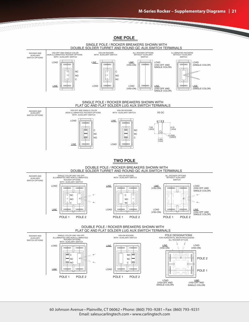
| 21 M-Series Rocker – Supplementary Diagrams

60 Johnson Avenue • Plainville, CT 06062 • Phone: (860) 793–9281 • Fax: (860) 793–9231Email: [email protected] • www.carlingtech.com
22 | M-Series Circuit Breaker - Time Delay Curve
Notes: 1 Delay Curves 12,14, 22, 24, 32, 34, 62, 64, 72, 74, 92, 94: Breakers to hold 100% and must trip at 135% of rated current and greater within the time limit shown in this curve.2 Delay Curves 10, 20, 30: Breakers to hold 100% and must trip at 150% of rated current and greater within the time limit shown in this curve.3 All Curves: Curve data shown represents breaker response at ambient temperature of 77°F (25°C) with no preloading. Breakers are mounted in standard wall-mount position.4 The minimum inrush pulse tolerance handling capability is 12 times the rated current on standard delays and 18 times the rated current on high inrush delays. These values are based on a 60 Hz 1/2 cycle, 8.33 ms pulse. High inrush delays should be specified for applications with high initial surge currents of short duration, such as switching power supplies, highly capacitive loads and transformer loads.
Medium Medium D4
Instantaneous
Short Short D2
Dual Rated AC/DC

60 Johnson Avenue • Plainville, CT 06062 • Phone: (860) 793–9281 • Fax: (860) 793–9231Email: [email protected] • www.carlingtech.com
60 Johnson Avenue • Plainville, CT 06062 • Phone: (860) 793–9281 • Fax: (860) 793–9231Email: [email protected] • www.carlingtech.com
| 23 Notes
* Intentionally left blank

Worldwide HeadquartersCarling Technologies, Inc.
60 Johnson Avenue • Plainville, CT 06062Phone: (860) 793-9281 • Fax: (860) 793-9231
Email: [email protected] • www.carlingtech.com
East Region Sales Office, CT • [email protected] Region Sales Office, IL • [email protected]
West Region Sales Office, CA • [email protected]
Asia-Pacific HeadquartersCarling Technologies, Asia-Pacific Ltd.,
Kowloon, Hong KongInt + 852-2737-2277 • Fax: Int + 852-2736-9332
Email: [email protected]
Shenzhen, China • [email protected], China • [email protected]
Pune, India • [email protected], Taiwan • [email protected]
Yokohama, Japan • [email protected]
Europe/Middle East/Africa HeadquartersCarling Technologies LTD
4 Airport Business Park, Exeter Airport, Clyst Honiton, Exeter, Devon, EX5 2UL, UK
Int + 44 1392-364422 • Fax: Int + 44 1392-364477Email: [email protected]
GmbH, Germany • [email protected], France • [email protected]
REV_CB_M_07_2014

Mouser Electronics
Authorized Distributor
Click to View Pricing, Inventory, Delivery & Lifecycle Information: Carling Technologies:
MA1-B-34-430-1-A162-C MA1-B-34-615-2A26-2-C MD1-B-34-615-1-A36-B-C MB1-B-34-450-1-A27-B-C MA1-B-34-
450-1-A26-B-C MB1-B-34-450-1-A26-B-C MA1-B-74-630-1-A25-2-M MB2-B-34-610-1-A24-B-C MB2-B-34-615-1-A24-
B-C MB2-B-34-625-1-A27-B-C MB2-B-34-610-1-A27-B-C MB2-B-34-615-1-A27-B-C MB2-B-34-620-1-A27-B-C MA1-
B-34-475-1-A12-B-C MA1-B-34-450-1-A12-B-C MD2-B-34-610-1-A36-B-C MD2-B-34-615-1-A36-B-C MB2-B-34-420-
1-A24-B-C MB2-B-34-470-1-A24-B-C MF1-B-34-610-1-DB7-B-C MF1-B-34-620-1-DB7-B-C MF1-B-34-615-1-DB7-B-C
MA1-B-34-625-1-A26-B-C MB1-B-34-615-1-A27-B-C MA1-B-34-610-1-A26-B-C MA1-B-34-615-1-A26-B-C MB1-B-
34-610-1-A27-B-C MB1-B-34-615-1-A26-B-C MB1-B-34-610-1-A26-B-C MB1-B-34-625-1-A27-B-C MB1-B-34-620-1-
A26-B-C MA1-B-34-620-1-A26-B-C MB1-B-34-620-1-A27-B-C MB1-B-34-625-1-A26-B-C MA1-B-34-625-1-A32-B-C
MA1-B-34-625-1-A12-B-C MA1-B-34-615-1-A12-B-C MA1-B-34-610-1-A12-B-C MA1-B-34-620-1-A12-B-C MA1-B-94-
450-1-A86-B-C MA2-4-34-615-2-A22-7-C MA2-4-34-625-2-A22-7-C MA2-4-34-625-2-A32-7-C MA2-4-34-625-2-A36-
7-C MA2-A-03-615-1-A16-2-C MA2-A-03-615-1-A22-2-C MA2-A-03-615-1-A24-2-C MA2-A-03-625-1-A12-2-C MA2-
A-03-625-1-A12-B-C MA2-A-03-625-1-A14-2-C MA2-A-03-625-1-A16-2-C MA2-A-03-625-1-A21-2-C MA2-A-03-625-1-
A21-B-C MA2-A-03-625-1-A22-B-C MA2-A-03-625-1-A24-2-A MA2-A-03-625-1-A24-2-C MA2-A-03-625-1-A24-B-C
MA2-A-03-625-1-A84-2-C MA2-A-03-625-2-A21-2-C MA2-A-03-625-2-A35-B-C MA2-A-03-625-3-A24-2-C MA2-B-14-
615-1-A22-B-A MA2-B-14-620-1-A26-2-C MA2-B-14-625-1-A22-B-A MA2-B-14-625-3-A22-B-A MA2-B-20-420-1-A26-
2-D MA2-B-20-610-1-A22-B-E MA2-B-22-420-1-A24-B-D MA2-B-22-420-1-A26-2-D MA2-B-22-430-1-A14-B-D MA2-
B-22-450-1-A14-B-D MA2-B-22-450-1-A24-2-D MA2-B-22-475-1-A14-B-D MA2-B-22-475-1-A34-B-E MA2-B-22-610-
1-A25-B-C MA2-B-22-610-1-A25-B-D MA2-B-22-610-1-A26-B-D MA2-B-22-612-1-A24-2-D MA2-B-22-614-1-A24-2-D
MA2-B-22-615-1-A14-B-D MA2-B-22-615-1-A16-B-D MA2-B-22-615-1-A26-B-D MA2-B-22-615-1-A32-2-D MA2-B-
22-615-1-A36-1-D MA2-B-22-615-1-A36-B-D MA2-B-22-620-1-A24-B-C MA2-B-24-410-1-A24-B-D MA2-B-24-420-1-
A14-B-D MA2-B-24-420-1-A24-B-D MA2-B-24-420-1-A26-B-D MA2-B-24-425-1-A24-B-D MA2-B-24-430-1-A14-B-D
MA2-B-24-430-1-A24-B-D MA2-B-24-440-1-A14-2-D MA2-B-24-440-1-A14-B-D MA2-B-24-440-1-A15-B-D MA2-B-24-
440-1-A16-B-D MA2-B-24-440-1-A24-B-D MA2-B-24-440-3-A15-B-E MA2-B-24-450-1-A14-1-D