M2M Mission Critical 008 07122010 - sgemfinalreport.fisgemfinalreport.fi/files/M2M Mission Critical...
36
<Document ID> M2M <0.08> Mission Critical Thoughts 2010-12-07 1 (36) Owner: Sampo Yliraasakka . SGEM WP 4.1.4: Next generation ICT-solutions for network management M2M Mission Critical Thoughts Version 0.08
Transcript of M2M Mission Critical 008 07122010 - sgemfinalreport.fisgemfinalreport.fi/files/M2M Mission Critical...

<Document ID> M2M <0.08> Mission Critical Thoughts 2010-12-07
1 (36)
Owner: Sampo Yliraasakka
.
SGEM WP 4.1.4: Next generation ICT-solutions for network management M2M Mission Critical Thoughts Version 0.08

<Document ID> M2M <0.08> Mission Critical Thoughts 2010-12-07
2 (36)
Owner: Sampo Yliraasakka
.
Version History
Version Date Handled by Comments
0.01 First version Sampo Yliraasakka Arto Rantala
Such to open discussions
0.03 Sampo Yliraasakka
0.04 Sampo Yliraasakka
0.05 5th July 2010 Sampo Yliraasakka
0.06 18th August 2010
Sampo Yliraasakka
0.07 26th November 2010
Sampo Yliraasakka
0.08 7th December 2010
Sampo Yliraasakka

<Document ID> M2M <0.08> Mission Critical Thoughts 2010-12-07
3 (36)
Owner: Sampo Yliraasakka
.
Table of contents
1 Introduction....................................................................................... 5
1.1 Document Overview....................................................................................................... 5 1.2 Scope and Readership................................................................................................... 5 1.3 Definitions and Terminology........................................................................................... 5 1.4 Related Documents and specifications........................................................................... 5
2 Power utility operational communication network.............................. 6
2.1 Substation to Substation network ................................................................................... 6 2.2 InterSubstation network.................................................................................................. 7
3 Power utility operational applications ................................................ 7
3.1 Introduction .................................................................................................................... 7 3.2 Substation Control.......................................................................................................... 8 3.3 Substation Data Analysis ............................................................................................... 8 3.4 Real Time Protection and Automation ............................................................................ 8 3.5 Substation Automation Platform Management ............................................................... 9 3.6 Commercial Applications................................................................................................ 9 3.7 Substation Management ................................................................................................ 9 3.8 Site Working................................................................................................................... 9 3.9 Security Applications.................................................................................................... 10 3.10 Substation Operational Voice System .......................................................................... 11 3.11 Collaborative Multi-media Communications.................................................................. 11
4 Applications Performance Requirements ........................................ 11
4.1 Introduction .................................................................................................................. 11 4.2 Table of Performance Requirement for Operational applications.................................. 12
5 Network evolution toward packet based.......................................... 16
5.1 Introduction .................................................................................................................. 16 5.1.1 NG-SDH and Packet network....................................................................................... 16 5.1.2 Packet network............................................................................................................. 17 5.2 IEC 61850.................................................................................................................... 17 5.2.1 Introduction .................................................................................................................. 17 5.2.2 Intersubstation communication model .......................................................................... 18 5.2.3 IEC 61850 Performance Requirements........................................................................ 19 5.3 TCP/IP Scada .............................................................................................................. 21 5.4 Substation Operational Voice ....................................................................................... 23 5.4.1 Mobile communications................................................................................................ 25 5.4.2 Example of operational voice requirements.................................................................. 25
6 Teleprotection................................................................................. 27
6.1 Introduction .................................................................................................................. 27 6.1.1 Example of Teleprotection communication requirements ............................................. 28
7 Intersubstation communication protection....................................... 29
7.1 Introduction .................................................................................................................. 29 7.2 IEC 62439-3 Parallel Redundancy Protocol (PRP)....................................................... 29 7.3 IEC 62439-3 High-availability Seamless Redundancy (HSR) ....................................... 29

<Document ID> M2M <0.08> Mission Critical Thoughts 2010-12-07
4 (36)
Owner: Sampo Yliraasakka
.
7.4 IEEE 802.1w Rapid Spanning Tree Protocol (RSTP) ................................................... 30 7.5 Dual homing (dual link) redundancy ............................................................................. 31
8 Appendix Use cases: ...................................................................... 31
8.1 Wide area measurement system.................................................................................. 31
9 Appendix abbreviations .................................................................. 33
10 Appendix references:...................................................................... 35

<Document ID> M2M <0.08> Mission Critical Thoughts 2010-12-07
5 (36)
Owner: Sampo Yliraasakka
5
1 Introduction
This document lists some Mission Critical application and tries to put some time values or measurable values to describe what mission critical real means.
1.1 Document Overview
Left blank
1.2 Scope and Readership
This document is written for the internal use of the M2M project group.
1.3 Definitions and Terminology
See point Appendix abbreviations
1.4 Related Documents and specifications
See point Appendix references
<Document ID> M2M <0.08> Mission Critical Thoughts 2010-12-07
6 (36)
Owner: Sampo Yliraasakka
6
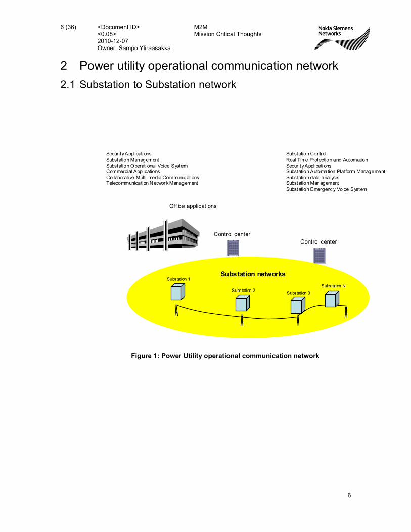
2 Power utility operational communication network
2.1 Substation to Substation network
Control center
Control center
Off ice applications
Substation networks
Substation Control
Real Time Protection and Automation
Security Applicati onsSubstation Automation Plat form Management
Substation data anal ysisSubstation Management
Substation Emergency Voice System
Security Applicati ons
Substation Management
Substation Operati onal Voice SystemCommercial Applications
Collaborati ve Multi-media CommunicationsTelecommunication N etwor k Management
Substation 1
Substation 2Substation 3
Substation N
Figure 1: Power Utility operational communication network

<Document ID> M2M <0.08> Mission Critical Thoughts 2010-12-07
7 (36)
Owner: Sampo Yliraasakka
7
2.2 InterSubstation network
For internal use only
/ 3 © Nokia Siemens Networks
Substation Communication
Substation Human Machine Interface(HMI)
IED
Substation Controler
Communication ArchitectureCommunication Architecture
Scada
IED IED IED
Wired
Process equipment
VoltageMeasurement
Switchgear Meas Meas
Figure 2: Reference picture for substation communication
3 Power utility operational applications
3.1 Introduction
Only operational applications relative to the power delivery process have been covered. This includes applications in the HV substation and in the Control Centre, as well as the associated Operation Support applications connecting the Utility office to the HV substation or to the Control Platforms.
Corporate enterprise data networking applications in the Utility office, being very similar to any other large enterprise corporate IT, have not been treated in this document beyond the Operation Support applications of the Utility.
Two important drivers for the migration from point-to-point multiplexed circuits to the network-oriented Ethernet are the TCP/IP SCADA and the new substation automation process through IEC 61850 standard.

<Document ID> M2M <0.08> Mission Critical Thoughts 2010-12-07
8 (36)
Owner: Sampo Yliraasakka
8
3.2 Substation Control
Substation control refers to all information exchange, within the substation or external to the substation, that provides access to substation “real time” operational data, time-stamped or non-time-stamped indications relative to status changes, alarms, measurements of electrical quantities, and commands sent to alter the state of operational equipment. The important applications related to substation control are:
Local Substation Control
Energy Management SCADA
Remote Substation Control
3.3 Substation Data Analysis
This is data collected and used (generally off-line) either to evaluate events at the substation or to provide confirmation of device configuration.
Event Reports – typically log files and reports generated by an event recorder or historical system which provide information on the change of state of operational equipment
Oscillography File Transfer – typically event triggered fault records generated by a protection device or fault recorder. These may contain digital events and analogue waveforms.
Confirmation of Parameters/ Upload of Setting – data files uploaded to provide information on the actual configuration of a device.
3.4 Real Time Protection and Automation
This is data which is transferred between devices in real time to ensure correct protection, operation and substation automation.
Protection and Protection initiated automation – Data and signals used to initiate Circuit Breaker Tripping and high speed reclosure, operating in a timeframe of less than 100ms.
Teleprotection – Data and signals sent to remote substations to accelerate release or block Circuit Breaker tripping. Usually covers the exchange of monitoring and command information to protect operational equipment.
Zone Protection and Wide Area Control schemes – Data and signals required by automation systems that operate across zones of the transmission system on a wide area inter-substation basis.

<Document ID> M2M <0.08> Mission Critical Thoughts 2010-12-07
9 (36)
Owner: Sampo Yliraasakka
9
Low Speed Substation Automation – Data and signals used to initiate intra substation applications, which operate in a timeframe of more than 100ms. Management of outages on distribution networks in real time.
3.5 Substation Automation Platform Management
This is data required to manage the configuration and performance of the SAS itself. The data types identified are:
Substation Automation System Monitoring Data – Supervision data relating to the operational performance, health and condition of the SAS
Configuration downloading – File transfer of site specific application configuration data files or parameter settings
3.6 Commercial Applications
This is data collected for the purpose of energy trading and billing or has an impact on the commercial operation of the utility business.
Revenue Metering – This is time integrated Energy Data at a commercial interface or boundary used for energy charging and billing. Introducing meters as rather inexpensive IP units in a well distributed computer network will give the possibility to increase the precision (density and frequency) of metering resulting in accurate payment for delivered services.
Energy Quality Monitoring – This is data related to agreed quality of service criteria, where energy is transferred at commercial interfaces or boundaries, which could be subject to financial penalties.
3.7 Substation Management
This is data collected to monitor plant and equipment condition or relates to environmental factors.
HV Apparatus Health and Performance Monitoring – data relating to plant condition and performance, generally used to indicate maintenance requirements, its duty cycle, capability and loading ability
Weather and environment Monitoring – data relating to substation environmental factors such as temperature and pollution etc., which may be used to influence utility business decisions.
3.8 Site Working
This is data required by site personnel in the execution of site related duties.

<Document ID> M2M <0.08> Mission Critical Thoughts 2010-12-07
10 (36)
Owner: Sampo Yliraasakka
10
Safety Information – data used by site personnel to ensure that plant and equipment to be maintained is isolated, secured and earthed. (Tagging)
Online Documentation – data used by site personnel to carry out their tasks at the substation (e.g. maintenance manuals and schedules, drawings and plans). Documentation is an essential base for efficient management of utility infrastructure. Pictures and video add particularly useful information in the dispersed environment of the power delivery system. These applications require a broadband network in order to meet an acceptable time performance. The introduction of inexpensive GPS equipment and commercial mapping applications makes Geographical Information Systems (GIS) an important tool for field based maintenance personnel. Connecting to maintenance applications in the substations and downloading accurate maps, pictures and work orders may effectively economize time.
However, the use of GIS and increasingly automation of data acquisition of power line infrastructure (e.g. laser scanning) leads to heavily growing data volumes and need for scalable ICT infrastructure.
If Security Tagging is not yet accepted to be “virtual”, the requirement for on-line documentation is very well identified. The use of networking is to be coordinated through the Security policy of the Power Utility.
3.9 Security Applications
Data required to visualize and to prevent threats to the physical substation and unauthorized access.
Video-surveillance – Surveillance of unmanned substations and even manned stations during the night have become increasingly important due to danger from sabotage and the possibility of damage from high voltage installations to the public (authorities demand). Traditional video surveillance equipment based on proprietary solutions has been, and still is, rather expensive.
Introducing rather inexpensive, semi intelligent IP based cameras opens a new road to better control of the exterior border of substations.
Surveillance cameras using Video over IP are widely being used. Ideally High Definition video would be necessary in order to provide the necessary resolution, however, the traffic volume makes these systems very difficult to implement in a generalized manner.
Video-surveillance can also be used for remote “visual” verification of grounding for work in the substation or on the power line as required by safety regulations and infra-red camera systems may be employed as a means of condition monitoring for certain substation assets.

<Document ID> M2M <0.08> Mission Critical Thoughts 2010-12-07
11 (36)
Owner: Sampo Yliraasakka
11
Access Control – data relating to potential threats to the substation communication systems and general configuration data which must be prevented from disclosure, modification or destruction.
IP networking is the appropriate way to deal with these applications.
3.10 Substation Operational Voice System
The implementation of the Operational hotline telephone in the HV substation is evolving into IP telephony and therefore it becomes an Ethernet transported data service.
Switched Telephone networks incorporate IP telephony as a consequence of switch technology change, network change and also in the objective of cost reduction and new features (e.g. connection to mail systems and calendar systems). QoS control and VPN techniques (or even physical separation) mechanisms may be employed in order to ensure separation from other communication services.
3.11 Collaborative Multi-media Communications
The possibility to distribute office applications like mail, word processing etc and ERP solutions like project control and time registration will increase the efficiency in local branch offices. IT-support may be effectively administered from a corporate central site or even be part of the decentralized organization.
Presence of Ethernet and IP in substations and given sufficient capacity and efficient compression technology the network will serve as useful video conference system. The increased focus on energy saving and CO2 reduction is encouraging to reduce travelling thus supporting solutions for remote administration.
4 Applications Performance Requirements
4.1 Introduction
This section presents the traffic volume and performance requirements and constraints associated to operational Ethernet applications. It is practically impossible to put precise figures to the performance requirements which are by definition dependent on applications, voltage levels of the power network, company and national practice, etc. Here the table intends to give only an outline of data communication capabilities that must be taken into consideration when dimensioning Ethernet connectivity.

<Document ID> M2M <0.08> Mission Critical Thoughts 2010-12-07
12 (36)
Owner: Sampo Yliraasakka
12
4.2 Table of Performance Requirement for Operational applications

<Document ID> M2M <0.08> Mission Critical Thoughts 2010-12-07
13 (36)
Owner: Sampo Yliraasakka
13
Service Description & Status Traffic Volume Traffic Profile Availability Response Time Data Flow
Substation Control
Local Substation Control Substation local
Energy Management / Scada Only the traffic out of
substation is considered Substation to Control Centre
Remote Substation Control
Measures: 2-5 per bay, 40 bytes
Alarms: (1 – 20) , per bay, 40
bytes
Indications : (1-8) events/ bay,
40 bytes
Commands: ( 1-5 per bay) , 32
bytes
Measures : Periodic
& on threshold
Alarms: event driven
Indications : event
driven
Commands :on
demand
Critical 1 – 10 sec
1 – 3 sec
1 – 3 sec
0.5 – 3 sec
Control Centre to Substation
Real Time Protection and Automation
Protection and Protection
initiated automation
At present implemented
through dedicated
channel and continuous
operation (64kbps –
2Mbps)
A few bytes Event driven
Very Critical
5 – 50ms
depending on
application
Substation local
Substation to substation
Tele-protection
At present implemented
through dedicated
channel and continuous
operation
(64kbps – 2Mbps)
Up to 6 commands / feeder Event driven
Very Critical
5 – 50 ms
depending on
application
Substation to substation
Zone Protection and Wide
Area Control schemes
Around 100 bytes per phasor
(including UDP/IP/Ethernet
overhead)
Event driven
Very Critical
20 – 50 ms
Substation to substation
Substation to Control Centre
Low Speed Substation
Automation A few bytes (5 – 10) Event driven
Critical
300ms to few sec
Substation local
Substation to substation
Time Synchronization and
distribution From event record tag A few bytes Periodic
Critical 1 – 60 pulse per
minute Substation local

<Document ID> M2M <0.08> Mission Critical Thoughts 2010-12-07
14 (36)
Owner: Sampo Yliraasakka
14
Service
Description & Status Traffic Volume Traffic Profile Availability Response Time Data Flow
Security Applications
Video-surveillance Several Mbytes Event driven Fairly
Important 5 – 60 sec
Cyber-security remote
management
Remote access to
firewall and barrier data Several Mbytes Event driven
Not critical
Access Control Few bytes to 1 Kbyte Event driven Important 5 – 60 sec
Substation to Management Platform
Substation Automation Platform Management
Substation Automation
System Monitoring Data
Up to 100 bytes for a complex
failure Event driven
Not critical
Configuration downloading Several Kbytes On demand Not critical few sec
Substation local
Substation to substation
Substation data analysis
Event Reports
Up to 100 info per fault
1 info < 80 bytes
Not critical
Oscillography File Transfer
Fault locator
There are protections
that register not only
the oscillography but
also estimates where
the fault is located
1 – 5 files / fault
1 file = 20 – 500 kbytes
Not critical
Confirmation of Parameters/
Setting uploading Around 100 kbytes per bay
Depends on network
and applications
Event driven, Burst
or on demand
Not critical
From few seconds
to several minutes Substation to Control Centre
Substation Management
HV Apparatus Health and
Performance Monitoring
Condition Monitoring
& Asset Management Few kbytes
Periodic and event
driven
Not critical Minutes Substation to Management Platform
Weather and environment
Monitoring Few kbytes
Periodic and event
driven
Not critical Up to 60min Substation to Management Platform
Site Working
Safety Information
Exchange of procedure
progress to de-energize
a circuit
Several kbytes On demand
Very critical
1 min
Substation to substation
Substation to Control Centre
Online Documentation Several Mbytes On demand Not critical Minutes Substation to Central Server

<Document ID> M2M <0.08> Mission Critical Thoughts 2010-12-07
15 (36)
Owner: Sampo Yliraasakka
15
Service
Description & Status Traffic Volume Traffic Profile Availability Response Time Data Flow
Substation Operational Voice System
Substation Control Room
Emergency Telephone
1 – 3 Telephone lines per
Substation On demand
Very critical Delay < 150ms
Jitter sensitive
Substation to Control Centre
Switched telephone access in
the substations
Connections between IP
PBX, Call Servers and
remote telephone sets
10 - 50 telephone extensions On demand
Not critical Delay < 150ms
Jitter sensitive
Substation to substation
Substation to Control Centre
Commercial Applications
Revenue Metering Several kbytes Periodic Not critical Few min Substation to Management Platform
Energy Quality Monitoring 100s of kbytes Burst or on demand Not critical 30 min Substation to Control Centre
Collaborative Multi-media Communications
File Transfer, web-traffic,
Client-server applications
Videoconferencing
Several Mbytes per session Burst, on demand
Not critical Seconds to few
minutes Substation to Central Platform
Telecommunication Network Management
SDH/PDH and IP Network
Fault Management and
Performance Monitoring
Point-to-point links
connecting Mediation
Device to the
Management Centre
Several kbytes Periodic and event-
driven
Not critical
Second to few
minutes Substation to Management Platform

<Document ID> M2M <0.08> Mission Critical Thoughts 2010-12-07
16 (36)
Owner: Sampo Yliraasakka
5 Network evolution toward packet based
5.1 Introduction
5.1.1 NG-SDH and Packet network
/ 7 © Nokia Siemens Networks
Control and Emergency
Office Services
CIRCUITSWITCHING
NG-SDH and Ethernet Evolution
Connection MasterConnection Master
TDMI/Fs
TDMI/Fs
PacketI/Fs
PacketI/Fs
SDHSDH SDHProt
SDHProt ETHETH
video
Most Critical Applications(e.g. Tele-protection)
IP PhoneSub Station 1
STM-1/4/16
Protected STM-1/4 or Eth Ring
Station officeApplications
NG-SDH
EmergencyLine (1-3)
NxE1
E-LINE/EVPL
Voice
ProcessApplications(SCADA)
Nx64k
E-LAN
video
Sub-Network 3
Sub-Network 4
Sub-Network 1
IP, Internet
CMSDH
CMSDH
Control Site_1IP / MPLS
Control Site_2
VoIP PABX /SoftSwitch
Video Services
VoIP
E-LAN/EVPLAN
Connection MasterConnection Master
TDMI/Fs
TDMI/Fs
PacketI/Fs
PacketI/Fs
SDHSDH SDHProt
SDHProt ETHETH
Connection MasterConnection Master
TDMI/Fs
TDMI/Fs
PacketI/Fs
PacketI/Fs
SDHSDH SDHProt
SDHProt
E1Trunk
E1Trunk
VoIP Services
E-LINE/EPL
E-LINE/EPL
E-LAN/EVPLAN
CSN
CMSDH
CMSDH
Sub-Network 2
Sub Station 2 Sub
Station N
CMSDH
CMSDH
SDHP
SDHP
STM-4/16 Ring
NxGigE, FELink Aggregation
Process Network,LAN Network, ..
IEEEC37.94/G.703
LAN Services/Scada, EMS,
Emergency voice
TDMLL Network
Figure 3: Example of NG-SDH network

<Document ID> M2M <0.08> Mission Critical Thoughts 2010-12-07
17 (36)
Owner: Sampo Yliraasakka
5.1.2 Packet network
/ 8 © Nokia Siemens Networks
Packet Based Network
Office Services
PacketI/Fs
PacketI/Fs
PacketI/Fs
PacketI/Fs
ETHETH ETHETH TDMTrunk
TDMTrunk
video
Most Critical Applications(e.g. Tele-protection)
IP Phone
Sub Station 1
Protected Ethernet Ring
Station officeApplications
EmergencyLine (1-3)
E-LINE/EVPL
IP Phone
RTU
ProcessApplications
Eth
E-LAN
video
Sub-Network 3
Sub-Network 4
Sub-Network 1
IP, Internet
Control Site_1IP / MPLS
Control Site_2
VoIP PABX /SoftSwitch
VoIP
E-LAN/EVPLAN
PacketI/Fs
PacketI/Fs
ETHETH ETHETH TDMTrunk
TDMTrunk
PacketI/Fs
PacketI/Fs
SDHSDH ETHETH TDMTrunk
TDMTrunk
VoIP Services
E-LINE/EPL
E-LINE/EVPL
E-LAN/EVPLAN
CSN
Sub-Network 2
Sub Station 2 Sub
Station N
NxGigELink Aggregation
GOOSE
Opt Eth
TCP / IP - Scada
E-LINE/EPL
Process Network,LAN Network, ..
xDSLxDSLxDSLxDSL
Control and Emergency(TDM)
Video Services
LAN Services/Scada, EMS,
Emergency voice
Figure 4: Example of Ethernet network
5.2 IEC 61850
5.2.1 Introduction
The scope of the standard IEC 61850 is to support the communication for all process oriented functions being performed in a substation. The goal of the standard is interoperability, i.e. the ability for IEDs from one or several manufacturers to exchange information and use the information for their own functions.
The standard IEC 61850 supports the free allocation of functions to Intelligent Electronic Devices (IEDs) and, therefore, supports any kind of system philosophy covering different approaches in function integration, function distribution, and SA architecture.
The standard contains an object-oriented data model that groups all data according the common user functions in objects called Logical Nodes (LN). All related data attributes are contained and defined in these Logical Nodes. The access to all the data is provided in a well defined way by the services of the standard, which aim to fulfill the performance requirements.

<Document ID> M2M <0.08> Mission Critical Thoughts 2010-12-07
18 (36)
Owner: Sampo Yliraasakka
The data model and services of the standard are mapped to a mainstream communication stack consisting of MMS, TCP/IP and Ethernet with priority tagging. These LAN-services cover the needs of IEC61850 in terms of Intra-station communication.
With the ongoing extension of the IEC61850 standards for Inter-Station communication1 and communication towards the Network Control Center, WAN networks come into the picture. LAN traffic with time critical IEC61850 content can be transported, in most cases, over the already existing utility SDH-network (� Ethernet over SDH). This approach allows running traditional services in parallel with IEC61850 traffic while benefiting from technical as well as commercial (� investment protection) aspects.
5.2.2 Intersubstation communication model
The IEC61850 communication services can be grouped into two general kinds of communication: Vertical and horizontal communication. Vertical communication in Substation automation is that which takes place between station and bay level devices. Vertical communication services are designated by IEC61850 for reading or writing data for control and monitoring applications, including file transfer. These are mapped on MMS (ISO9506) over TCP/IP. Control services are using acknowledged services on application level. Monitoring services relay on TCP/IP data integrity.
Stations bus
Process bus
GatewayStationComputer
HMI
Control ProtectionControl &Protection
Control Protection
Process interface
Station level
Bay level
Process levelSwitchgear (Primary technology, Process)
Parallel
wires
Station control NCC interface
Process interface Process interface
Horizontal Communication
Horizontal Communication
Vertical Communication
Stations bus
Process bus
GatewayStationComputer
HMI
Control ProtectionControl &Protection
Control Protection
Process interface
Station level
Bay level
Process levelSwitchgear (Primary technology, Process)
Parallel
wires
Station control NCC interface
Process interface Process interface
Stations bus
Process bus
GatewayStationComputer
HMI
Control ProtectionControl &Protection
Control Protection
Process interface
Station level
Bay level
Process levelSwitchgear (Primary technology, Process)
Parallel
wires
Station control NCC interface
Process interface Process interface
Horizontal Communication
Horizontal Communication
Vertical Communication
Horizontal Communication
Horizontal Communication
Vertical Communication
Figure 5: Intersubstation communication model
With Horizontal communication in IEC61850 we are talking mainly about the Generic Substation Event (GSE) model for exchanging time critical data (messages) between two or more IEDs using Ethernet multicast (see Fig.1, on bay level). The GSE service model of 61850- 7-2 details fast and reliable system-wide distribution of input and output data values.

<Document ID> M2M <0.08> Mission Critical Thoughts 2010-12-07
19 (36)
Owner: Sampo Yliraasakka
This GSE service uses a specific scheme of retransmission to achieve the appropriate level of reliability.
Sampling and digitization voltage and current measurement is defined in the standard to replace traditional I/O wiring. Protection IEDs base their decisions on current and voltage samples, measured by current and voltage transformer IEDs. A loss, or even a delay, bigger than 4ms between two consecutive samples prevents IEDs from functioning correctly.
Sample exchange can be basically seen as vertical communication. However, these samples are sometimes also distributed horizontally within the substation. An example would be the so-called bus bar voltage used to trigger protection relays. These samples have to be measured with a frequency of typically 4 kHz and have to be transmitted cyclically with a frequency of 1kHz. Since typically more then one IED requires the measured values, MAC layer multicast addressing is used. Within a substation typically 30 to 60 IEDs are transmitting these samples leading to a high rate of multicast load in case of just a single common network.
5.2.3 IEC 61850 Performance Requirements
The IEC 61850 structures Protection and Control functions in terms of Logical Nodes (LN) that may be located in different devices communicating through an Ethernet network. It is therefore essential for the proper performance of the Substation Automation System (SAS) functions the performance of the Ethernet LAN and particularly the “Transfer time” of messages between LNs.
The term “Transfer time” refers to the complete transmission time of a message between two physical devices connected by means of a communication system.
IEC61850 - Delay
Figure 6: Transfer Time

<Document ID> M2M <0.08> Mission Critical Thoughts 2010-12-07
20 (36)
Owner: Sampo Yliraasakka
The transfer time is defined as the addition of the processing time of the communications stack of the IED emitting the message (ta), the Ethernet network transmission time (tb), and the processing time of the communications stack of the IED receiving the message (tc). On the other hand, IEC61850-5 ( refer to [19]) specifies that the processing times ta and tc cannot surpass 40% of the total transmission time. As a result of this, tb has an upper limit of 20% of the transmission time, and this percentage equals 600 microseconds for the most restrictive case.
The standard IEC61850, in its part 5, states that the maximum transfer time for a given message cannot surpass certain values, depending on the message’s priority. Some of them, such as type I messages, require that this time shall not exceed 3 milliseconds.
Time constraints for different services are defined in IEC61850-5 and can be summarized as shown in figure shown below
Delay Message Type Description
Type Max
Ms
1 <10 Fast messages, typically for binary signals transmitted between
controllers attached to the same communication network (LAN). Even
faster times for high performance transmission applications.
2 <100 Medium speed messages; with a total transmission delay of less than
100ms.Type 2 is used for monitoring functions.
3 <500 Low speed messages with total transmission delay below 500ms,
typically used for parameter access.
4 4 Raw data messages with sampling.
5 >1000 File transfer functions.
6 Time synchronisation messages. Accuracy of 1ms (time tagging of events) and 0.1 ms (synchrocheck, point on wave switching) defined for
control and protection; down to 1 ms for synchronised sampling. Delay
is less critical than jitter. Time performance classes are depicted in table
15
7 >1000 Command message with access control are commands typically received from outside the SA system, which require authority checks.
.
Figure 7: Message types and delay ranges

<Document ID> M2M <0.08> Mission Critical Thoughts 2010-12-07
21 (36)
Owner: Sampo Yliraasakka
Time perf.
class
Accuracy Purpose
T1
T2
±1ms
±0.1ms
Time tagging of events on bay level
Time tagging of zero crossings and of data for the distributed synchro check. Time tags to support point on
wave switching.
T3
T4
T5
±25µs
±4µs
±1µs
Synchronised sampling and advanced functions.
Figure 8: Synchronization and time tagging
The use of Ethernet for substation communications with IEC61850 requires that:
EMC and environmental requirements be met by the communication equipment as stated in IEC 61850-3.
All links support 100Mbps, full-duplex interfaces throughout the plant.
Critical real-time data is transmitted with multicast communication throughout the plant and at the same time, traffic to be kept as localized as possible to the data sources and sinks.
The use of well-designed, and possibly dynamic VLANs, can help to solve this problem by filtering the relevant traffic. The VLAN identification can not be assigned per port of a switch but needs to be carried in the telegrams if optimum system operation is to be achieved.
The most important functions in a SAS relate to protection of the primary equipment. If this protection relies on communication, then it must be able to deal with an event avalanche of vertical traffic leaving horizontal communication still functional. Therefore using utility communication devices supporting IEEE 802.1p priorities with at least four priority queues is needed. Sampled values, GSE communication, and time synchronization should be configured to use a priority class that is assigned to the high priority queue in the relevant switches. Vertical communication uses TCP and is thus less susceptible to telegram loss, so it should be given low priority.
Redundancy on the Ethernet backbone level is easily achieved without affecting IEC61850 implementations on the IEDs. For protection, complete redundancy is required, meaning that the whole equipment (IEDs and network) is doubled up implying that no special redundancy solutions have to be chosen. In cases requiring redundancy down to the IED, different proprietary solutions are offered.
5.3 TCP/IP Scada
Still today, the widest employed communication mode for the substation RTU remains the Asynchronous Serial link through an RS-232 interface. The communication protocol associated to this mode has been standardized as IEC 60870-5-101 (IEC101), although many other protocols are still in use in legacy systems. It is suitable for multiple configurations such as point-to-point, star, multi-drop, etc. The great advantage of Serial link

<Document ID> M2M <0.08> Mission Critical Thoughts 2010-12-07
22 (36)
Owner: Sampo Yliraasakka
SCADA is its conceptual simplicity when associated to a circuit-based communication system: RTUs have independent circuits and can be backed-up by another circuit with fully separate routing across the network.
The major drawback to serial communication for SCADA is indeed its lack of flexibility and the large quantity of independent serial circuits which must be terminated and connected to a Front-end in the Control Centre. This implicates hundreds of RS-232 interface points, associated interface hardware and a great amount of cabling and connectors. Moreover, any change in the organization of the SCADA system, such as the transfer of the Control Centre to a new geographical location or the implementation of a Back-up Control Centre, shall require tremendous.
The principle of replacing end-to-end serial SCADA circuits by packet communication received considerable support with the advent of IP networking leading to TCP/IP based SCADA protocol IEC 60870-5-104, generally called IEC104. The high capacity optical network with modern SDH transmission provides the adequate infrastructure to deploy the required wide area Ethernet connections.
The IEC104 protocol was developed as an extension of IEC101, adapted for use in a TCP/IP environment through an Ethernet LAN interface at 10 or 100Mbps, although the bandwidth allocated to each RTU communications remains often around 10kbps. The application layer remaining largely unchanged, the amount of process-oriented data to be exchanged does not significantly increase through the use of IEC 104, even if new applications such as RTU-management and SW-updates may punctually consume more bandwidth than in IEC101.
Moving from Serial link to TCP/IP SCADA communications raises a number of issues that must be taken into account:
• Latency – RTU communication is time sensitive and high latency can degrade the overall performance of the SCADA system or even render the protocol completely inoperable through the time-out of the communication servers. Latency problems due to switching and routing infrastructure may be avoided through an appropriate design. It should be noted that the “real-time” requirements of RTU-cycles are generally in the range of seconds, as compared to order of magnitude smaller transmission times across a thoroughly designed SCADA Ethernet/IP infrastructure. The main issue here is therefore the number of intermediate nodes in the routing of SCADA information as well as the time for any encapsulation and concatenation.
• Path Redundancy and Resilience – SCADA RTU communications generally require independent normal and back-up communication routes. In an Ethernet/IP network environment, the problem of resilience is generally overcome through inherent IP routing mechanisms (e.g. OSPF routing), and/or through the protection mechanisms of the underlying SDH network (e.g. SDH ring protection). Adequate planning of OSPF-routing areas (to avoid unwanted management traffic and increased re-routing times), and appropriate predefined alternative routes in the SDH infrastructure, allow to keep high reliability and limited transmission times. Duplicated RTU routing independently from the network resilience is indeed possible but should be performed keeping in mind the independence of normal and back-up routes and no common point of failure.
• Restoration time – Restoration times in case of failure may be higher than with serial transmission, depending on the selected protection schemes. The original restoration mechanism of Ethernet, the Spanning Tree Protocol (STP) has a convergence time which depends upon the complexity of the Ethernet mesh and which may be too long for a SCADA system. More elaborate options such as Rapid Spanning Tree (RSTP)

<Document ID> M2M <0.08> Mission Critical Thoughts 2010-12-07
23 (36)
Owner: Sampo Yliraasakka
reduce this time, and as a general rule, the restoration time must be taken into consideration in the design of the SCADA Ethernet infrastructure.
• Multi-service integration – IP networking is generally considered as a multi-service network technology. However, it should be noted that migrating SCADA to TCP/IP does not necessarily allow the integration of additional services (office communications or IP voice services) within the same IP network. To provide the required QoS for a TCP/IP SCADA system, it is recommended to implement specific VLANs with dedicated bandwidth-allocation.
The use of TCP/IP in SCADA RTU communications allows to aggregate bandwidth from groups of RTU, increasing gradually towards the Control Centre, in such a way that only a few Ethernet interfaces are required at the Control Centre rather than the cabling of hundreds of modem-connections towards the front-end processor. Instead of uncounted wires, only few (redundant) LAN-connections are needed and the RTUs are addressed via their IP-address.
Moreover, the use of TCP/IP enhances considerably the flexibility of the SCADA communication system, facilitating the relocation of an RTU or a complete Front-end. The migration process for a large installed base from existing serial communications to TCP/IP is a major concern in many SCADA systems.
5.4 Substation Operational Voice
The implementation of the Operational hotline telephone in the HV substation is evolving into IP telephony and therefore it becomes an Ethernet transported data service.
Switched Telephone networks incorporate IP telephony as a consequence of switch technology change , network change and also in the objective of cost reduction and new features (e.g. connection to mail systems and calendar systems). QoS control and VPN techniques (or even physical separation) mechanisms may be employed in order to ensure separation from other communication services.
Highly reliable and secure voice communications are required for load dispatching and for network switching operations. At control centers, generating stations and switching substations, voice facilities are needed to allow operational staff to communicate quickly and efficiently. At times of disturbance on the system, the need for operational staff to communicate can be urgent. Normally, a private, highly secure operational telephone system is needed to provide the required facilities.
The voice facilities for operational use include:
• Direct (hotline) telephone lines from the Control Centre to all major operational sites’ control rooms
• Switched telephone service through PBX and a closed numbering scheme
• Additional redundancy and operation in situations of site isolation.
• Interconnection with the public telephone network.
• Voice and data traffic.

<Document ID> M2M <0.08> Mission Critical Thoughts 2010-12-07
24 (36)
Owner: Sampo Yliraasakka
• Mobile radio voice facilities for access to operational staff who visit facilities. (Mobile workforce communications is treated in a separate section).
The Operational telephone service is today evolving into IP telephony and becomes increasingly an Ethernet transported data service with particular time and bandwidth requirements.
Some of the specific features of operational voice service are as follows:
• Access restriction – Use of the operational voice service is confined to operational staff and not accessible to unauthorized users.
• High availability – Voice service access for the operational staff and in particular the access of the Control Centre to the network substations and generating plants is essential and must present a very high availability through adequate route resilience and equipment duplication.
• Resilience/fault tolerance – The voice service must remain available even in the event of network faults, node failure and route unavailability. In particular, a star-structured network in which the failure of a single node may jeopardize the system is not acceptable.
• Multiple homing (at least dual homing) of secondary sites and a mesh interconnection of the main nodes is generally required to achieve the required level of fault tolerance.
• Transfer to Backup Control Centre – In emergency situations leading to the migration of power system control to a Back-up Control Centre, the telephone network must rapidly adapt in order to transfer the telephone calls for the Control staff to the Back-up facility. This transfer must be possible even if the communication equipment in the main control centre is no longer operational (e.g. fire, flood or power breakdown).
• Very rapid call connection – The call establishment time must be in line with the operational emergency situations in which the voice communication may become necessary. In particular, the structure of the telephone network (number of cascaded transits) and the employed signaling scheme may greatly influence the call connection speed.
• Priority functions – These functions allow critical communications to be established even when all voice network resources are occupied. This can be performed through Forced Releasing of facilities which are used by less critical communications, or by reserving the usage of certain facilities (e.g. communication channels) for priority calls only. Similarly, critical calls can “Beak-in” into an established communication of a busy “called party”. Priority status can be attributed permanently to a given user line (i.e. Control Operator), or obtained dynamically through a code for a given communication.
• Caller identification and Call Queuing – Control centre operators need to identify automatically the source of incoming calls and to establish queues of “in progress” communications in order to interact with many sites, in particular at times of power system emergencies. In progress and queuing calls must be accessible and transferable between different Control centre operator positions.
• Mobile voice – Control centre facilities and large power plants telephone systems must have the capability to connect mobile voice terminals to fixed telephone extensions. Depending on the implemented mobile radio network, these connections may require the

<Document ID> M2M <0.08> Mission Critical Thoughts 2010-12-07
25 (36)
Owner: Sampo Yliraasakka
existence of PTT (Push to Talk) facilities and associated conversion of Half-Duplex to Full-Duplex voice communications.
• Ability to pre-select conference calls – The voice system must present the capability to establish pre-configured conference calls, in particular between operational staff in the control centre, in multiple substations and maintenance staff.
• Call Recording – Control centre voice facilities include voice recorders which constantly record all communications of the operators which will be archived periodically. These call recordings are essential in order to establish the sequence of events and instructions given by the Control Operators in emergency situations.
5.4.1 Mobile communications
EPUs make extensive use of mobile communications in the management and support of their infrastructure. In addition to traditional voice services for field-based operational workforce, the evolution of working practices is leading increasingly to mobile data networking applications connecting the maintenance staff to their support base, on-line documentation, and workshop applications such as spare parts database. In particular, systems can largely benefit from dedicated mobile data applications.
The operational mobile terminal units are evolving towards Smart phones and Tablet Computers for which ruggedized field-proof versions appear on the market. The mobile terminals keep field workers in continuous contact with support personnel and enables the real-time transmission of camera images and audio from the work site to the support base which can then provide precise support through voice interaction using a headset . This will improve work safety, accident prevention and work efficiency.
The implementation of data-rich mobile communication systems requires indeed the existence of high availability, disaster-resistant, high throughput wireless connectivity.
More than other communication services in the Utility, the provision model for mobile workforce communications is often under assessment. There is no doubt that the most economical solution is to use public mobile services which provide a high level of geographical coverage through extensive deployment of Base stations and related infrastructure, as well as continuous roll-out of new data services and applications.
However, an essential application of the mobile system, its usage by maintenance teams during power outages and in disaster recovery situations, is severely constrained due to public base stations’ insufficient power autonomy and severely degraded service accessibility/performance when the network is widely solicited (e.g. during a disaster situation).
Deploying a “security grade” private mobile radio system (e.g. TETRA) with a high coverage is costly and the roll-out of new data services and applications cannot be performed in pace with their public counterpart. This may lead utility staff to use public mobiles even if the company is equipped with its own private mobile facilities. Many Electrical Utilities, in particular those in the distribution sector, own or share with other critical users some type of private “security grade” mobile network.
5.4.2 Example of operational voice requirements
• Latency < 150 ms
• Bandwith requirements

<Document ID> M2M <0.08> Mission Critical Thoughts 2010-12-07
26 (36)
Owner: Sampo Yliraasakka
� G.711 circuit switched 64 kbps
� VoIP codecs
The bandwidth used depends also on the datalink (layer2) protocols. Several things influence the bandwidth used, payload size, ATM cell headers, VPN headers, use of header compression
Codec's theoretical bandwidth usage expands with UDP/IP headers [2]
Codec BR NEB G.711 64 Kbps 87.2 Kbps G.729 8 Kbps 31.2 Kbps G.723.1 6.4 Kbps 21.9 Kbps G.723.1 5.3 Kbps 20.8 Kbps G.726 32 Kbps 55.2 Kbps G.726 24 Kbps 47.2 Kbps G.728 16 Kbps 31.5 Kbps iLBC 15 Kbps 27.7 Kbps BR = Bit rate
NEB = Nominal Ethernet Bandwidth (one direction)
WCDMA CS voice 5.9 kbps
HSPA VoIP/CS 12.2kbps
HSPA CS 5.9 kbps
LTE VoIP 12.1kb/s [
• Voice Quality
Satisfied MOS value (ITU-scaled) > 4.
(MOS for G.729A is 3.9 but still widely use codec and appears to be quite acceptable)
• Standards for verifying voice quality
ITU specifications P.862.1 (PESQ), P.862.2 (PESQ WB), P.861 (PSQM), and P.800 (PAMS)
• Quality of Service
Although QoS is generally a layer 3 (and above) issue, the Ethernet layer provides Class of service by means of Priority Assignments which is a determining factor for the overall performance that can be obtained in the overall network.
• Redundancy
Several parallel voice systems can be in place depends on operator or importance of application.

<Document ID> M2M <0.08> Mission Critical Thoughts 2010-12-07
27 (36)
Owner: Sampo Yliraasakka
• Availability
Substation Control Room emergency telephone is likely required to be Hot Line type and not routed via switched network.
Many telephone service providers attempt to achieve "dial-tone availability" more than 99.999% of the time the telephone is taken off-hook, 5.3 minutes or less of downtime per year.
6 Teleprotection
6.1 Introduction
Electrical power system protection is provided to detect unwanted conditions on the system and to initiate actions to remove the unwanted condition. It is required to do this quickly and selectively, and often this is achieved by having two or more protection devices communicating with each other.
At the highest voltage levels, detection of faults and initiation of circuit isolation is required in typically less than one cycle of the power system cycle which means <20ms for a 50Hz system (e.g. Europe) or <17ms for a 60Hz system (e.g. America). Achieving this is constrained by the delays through the communications system. A knowledge of, or a prediction of, these communications delays - within an accuracy figure of microseconds - can be critical for the safe, effective and efficient operation of the power system.
Further, the protection is required 24/7 and so the communications channel must be similarly available (there is no time to make a ‘phone call to clear the fault!); continuously open, connected, and available communications channels are required for electrical power system protection.
Today, the protection of national and international electricity transmission grids has a dependency upon the characteristics of the communication networks. An unpredicted change in the communications can cause false protection operation with unwanted isolation of parts of the electricity network. In extreme cases this can lead to large scale blackouts, compromising safety and causing huge financial losses.
Over time, different protection techniques have been developed to take advantage of evolving communication technologies. Some techniques require the communication of “command” information (i.e. ON/OFF signalling); others require the communication of “data” (the transportation of power system signal values across the system), and the necessary characteristics of the communications can differ between these “command” and “data” applications.
Communications channels may be realised in the form of dedicated communications channels (for example, pilot wires, power line carrier, or dedicated fibre-optic links) or they may be leased from telecommunication service providers. Dedicated channels are normally under the full control of the electricity utility and are more likely to provide the predictable, deterministic operation required for electrical power system protection.
Now as we move towards “next generation network” communications technologies, whilst the interfaces presented to the electrical power system protection equipment remain the same, the management of the communications traffic behind the network is dynamic and some of the underlying characteristics reflected in the table that impact the correct operation of the

<Document ID> M2M <0.08> Mission Critical Thoughts 2010-12-07
28 (36)
Owner: Sampo Yliraasakka
protection, and hence of the operation, of the electrical power system, can no longer be assumed.
An important consideration for each of the different categories of protection scheme is the effect of the communication channel on overall operating times, parameters such as delay, delay variation, errors, channel availability, etc., may increase the protection operation time or even disable it. Following chapters analyse telecommunication performance, the key aspect that may influence protection operation, plus the most common problems found and possible remedies.
6.1.1 Example of Teleprotection communication requirements
The 400 kV HV line has been protected using as a primary protection differential relay and as a secondary protection distance rely. The protection relays have a communication channel between substations.
/ 11 © Nokia Siemens Networks11 © Nokia Siemens Networks
Distance Relay
Power Line
Differential Relay
Substation A
Distance Relay
Differential Relay
Substation B
Figure 9: Example of teleprotection communication requirements
Availability
• ≥ 99.97% (duplicate system), ≥ 99.9 % (single system)
Total protection time
• < 100 ms
Distance relay communication channel
• Latency < 25 ms
<Document ID> M2M <0.08> Mission Critical Thoughts 2010-12-07
29 (36)
Owner: Sampo Yliraasakka
• Differential delay (delay from substation A to substation B and from substation A to substation B) < 10 ms.
Differential relay communication channel
• Latency < 15 ms
• Differential delay < 0.9 ms (During the protection switch of communicatin channel both directions should be rerouted)
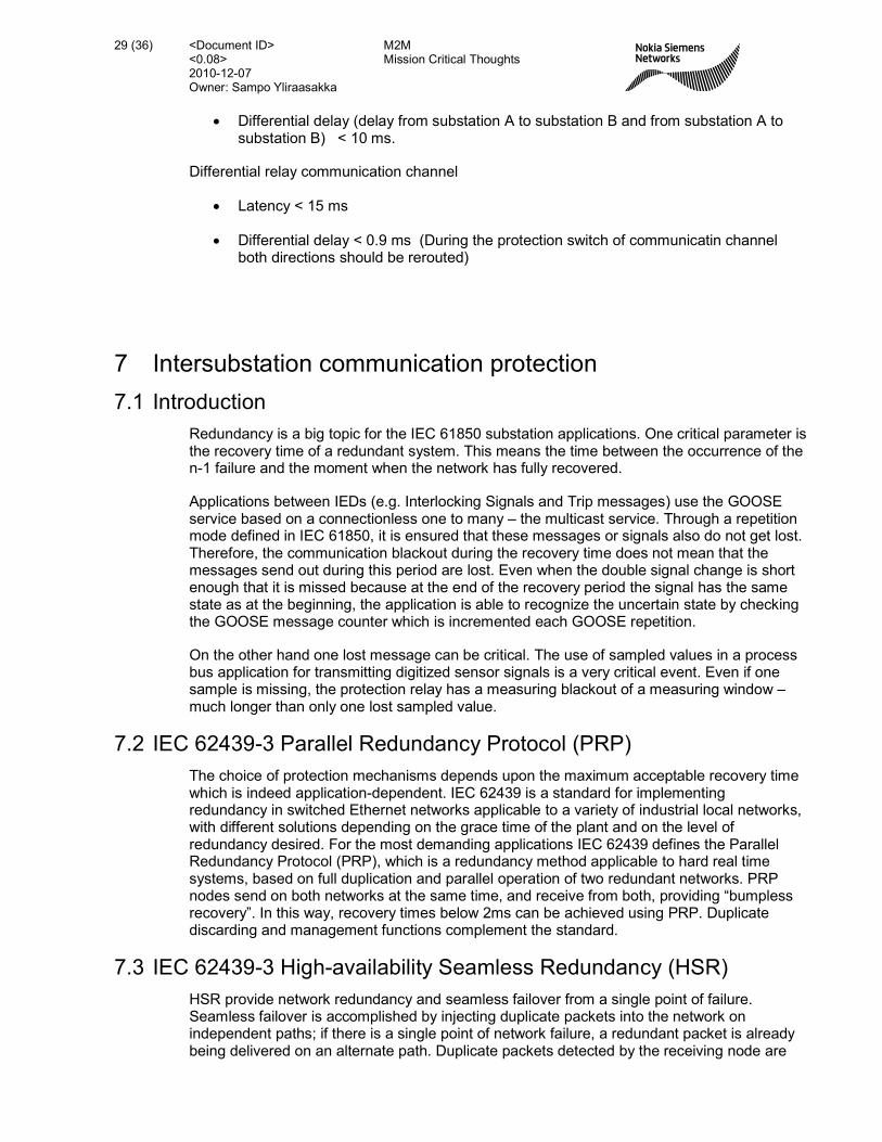
7 Intersubstation communication protection
7.1 Introduction
Redundancy is a big topic for the IEC 61850 substation applications. One critical parameter is the recovery time of a redundant system. This means the time between the occurrence of the n-1 failure and the moment when the network has fully recovered.
Applications between IEDs (e.g. Interlocking Signals and Trip messages) use the GOOSE service based on a connectionless one to many – the multicast service. Through a repetition mode defined in IEC 61850, it is ensured that these messages or signals also do not get lost. Therefore, the communication blackout during the recovery time does not mean that the messages send out during this period are lost. Even when the double signal change is short enough that it is missed because at the end of the recovery period the signal has the same state as at the beginning, the application is able to recognize the uncertain state by checking the GOOSE message counter which is incremented each GOOSE repetition.
On the other hand one lost message can be critical. The use of sampled values in a process bus application for transmitting digitized sensor signals is a very critical event. Even if one sample is missing, the protection relay has a measuring blackout of a measuring window – much longer than only one lost sampled value.
7.2 IEC 62439-3 Parallel Redundancy Protocol (PRP)
The choice of protection mechanisms depends upon the maximum acceptable recovery time which is indeed application-dependent. IEC 62439 is a standard for implementing redundancy in switched Ethernet networks applicable to a variety of industrial local networks, with different solutions depending on the grace time of the plant and on the level of redundancy desired. For the most demanding applications IEC 62439 defines the Parallel Redundancy Protocol (PRP), which is a redundancy method applicable to hard real time systems, based on full duplication and parallel operation of two redundant networks. PRP nodes send on both networks at the same time, and receive from both, providing “bumpless recovery”. In this way, recovery times below 2ms can be achieved using PRP. Duplicate discarding and management functions complement the standard.
7.3 IEC 62439-3 High-availability Seamless Redundancy (HSR)
HSR provide network redundancy and seamless failover from a single point of failure. Seamless failover is accomplished by injecting duplicate packets into the network on independent paths; if there is a single point of network failure, a redundant packet is already being delivered on an alternate path. Duplicate packets detected by the receiving node are

<Document ID> M2M <0.08> Mission Critical Thoughts 2010-12-07
30 (36)
Owner: Sampo Yliraasakka
removed from the network. Redundancy Boxes (Redboxes) will enable non-HSR nodes to connect to an HSR network. Devices with integrated HSR modules will be able to connect directly to the network.
For internal use only
/ 10 © Nokia Siemens Networks
HSR
workstation
loggerprinter
GPS aux
RedBox
bay
node
bay bay bay
GPS main
node node node
COM
NCC
Figure 10: High-availability Seamless Redundancy (HSR)
7.4 IEEE 802.1w Rapid Spanning Tree Protocol (RSTP)
IEEE 802.1w Rapid Spanning Tree Protocol (RSTP) was a further evolution of the 802.1D Spanning Tree Protocol. It replaced the settling period with an active handshake between bridges that guarantees topology information to be rapidly propagated through the network. In this way, it allows for the creation of fault tolerant ring network architectures that can reconfigure in milliseconds.
RSTP also offers a number of other significant innovations, including:
• Topology changes in RSTP can be originated from and acted upon by any designated bridge, leading to more rapid propagation of address information unlike topology changes in STP which must be passed to the root bridge before they can be propagated to the network.
• RSTP explicitly recognizes two blocking roles, alternate and backup port roles, including them in computations of when to learn and forward while STP recognizes one state, blocking, for ports that should not forward.
• RSTP bridges generate their own configuration messages, even if they fail to receive one from the root bridge. This leads to quicker failure detection but STP relays configuration messages received on the root port out its designated ports. If an STP

<Document ID> M2M <0.08> Mission Critical Thoughts 2010-12-07
31 (36)
Owner: Sampo Yliraasakka
Bridge fails to receive a message from its neighbour it cannot be sure where along the path to the root a failure occurred.
• RSTP offers edge port recognition, allowing ports at the edge of the network to forward frames immediately after activation while at the same time protecting them against loops.
While providing a much better performance than the STP, the IEEE 802.1w RSTP still requires up to a few seconds to restore network connectivity when a topology change occurs. A revised and highly optimized RSTP version is defined in the IEEE standard 802.1D-2004 edition. The IEEE 802.1D-2004 RSTP reduces network recovery times to just milliseconds and optimizes RSTP operation for various scenarios.
7.5 Dual homing (dual link) redundancy
In a dual homing configuration, the two interfaces in an IED and in a substation controller have two interfaces. One is active; the other is actively monitoring the backup link if it is still usable.
In the case of a failure the IED checks the missing link and switches over to the reserve link. It sends out a special message in order to establish the alternative path. This establishment is reduced to the missing link only - the recovery time is very fast.
This type of redundancy is described in principle in IEEE 802.1d but often completed with some proprietary functionality.
8 Appendix Use cases:
8.1 Wide area measurement system
General communication configuration
Figure 11: Example of Wide area measurement system
PMU
PMU
Phrasor data Consentrator (PDC) CSP’s
SDH or Eth MPLS
Eth
Eth
Eth
Voltage/Angle Stability monitor
To SCADA voltage, angle,
frequency
Data storage

<Document ID> M2M <0.08> Mission Critical Thoughts 2010-12-07
32 (36)
Owner: Sampo Yliraasakka
Wide Area Measurement and Monitoring provides a GPS-synchronized snap-shot of the power system through the acquisition of complex parameters (amplitude and phase) across the power network. It enables a better visibility of power flow across the system incorporating dispersed generation and multiple Utilities. The collected complex parameters are Bus voltages, line currents, etc. The Phasor Measurement Unit (PMU) is the acquisition device in the HV substation, collecting time-tagged phasors.
Measurements are transmitted to a central platform generally through a Phasor Data Concentrator (PDC) for different applications. These different levels of wide area applications have very different requirements in terms of information exchange and consequently telecommunication service [8].
• Post-incident analysis and static modeling applications are offline systems where collected data is used to analyze the cause of an event or to adjust the behavior model for a system. Data can be collected continuously, daily or only on request. The communication service can be a TCP/IP file transfer service with no real time constraint.
• Visualization and Situational Awareness applications collect data from sites and display them for human operator observation. These applications which constitute the great majority of present day systems have time requirements which are those of a human operator and must additionally present a level of sample loss unperceivable by the human operator.
• Monitoring & Decision Support systems use collected data to produce analytical information helping operators respond to grid events and to position the grid for improved security and resilience. Stability diagrams and corresponding voltage collapse margins, as well as different monitoring applications (Voltage & Frequency stability, Power Oscillations, Line Temperature, etc.) are among these applications. Monitoring and decision support applications have time constraints which are similar to power system SCADA.
• Closed Loop Applications are those which incorporate collecting of data from the grid, processing, automatic recognition of a pattern, and remedial action upon the grid. The systems are used for emergency situation control and special protection applications. Closed loop synchrophasor applications are not yet widely implemented and their critical real-time nature necessitates particular attention on time control. Furthermore the decision to act automatically upon the network in real-time (operation time second or less and latency 10 ms … 100 ms) means that the data set (from different locations and sample stack from each point) must be complete, that is to say almost lossless. Providing lossless data across a telecom network generally implies error recovery which is constrained by time limitations.
PMU operation is specified by IEEE C37.118 which defines phasor construction using the GPS-satellite timing signal, as well as the phasor’s data format. The exact data volume associated with the transmission of a data packet from a PMU varies depending on the incorporated parameters and the way each of them is coded (i.e. floating point or not, etc.) but can be assumed to be around 80 – 100 octets. This data volume is to be transferred across the network at a rate which is governed by the sampling frequency of the PMU. The sampling frequency is expressed as a number of (or a fraction of) AC cycles. It is often 25 (or 30) samples per second corresponding to one sample every two cycles to 100-120 samples per second corresponding to two samples every cycle (Nyquist Rate). This latter rate allows the processing of the signal corresponding to the AC fundamental wave.

<Document ID> M2M <0.08> Mission Critical Thoughts 2010-12-07
33 (36)
Owner: Sampo Yliraasakka
The required communication throughput is then somewhere in the range of 16 – 100 kbps for a 50Hz power system although PDC links may require few hundred kbps up to 1Mbps or more.
9 Appendix abbreviations
ATM Asynchronous Transfer Mode
BAY A substation consists of closely connected sub parts with some common functionality. Example is the switchgear between an incoming or outgoing line. These subparts are called ‘bays’
CBR Constant Bit Rate
CMDB Configuration Management Data Base
CMMI Capability Maturity Model Integration
COBIT Control Objectives for Information (and related) Technologies
CRM Customer Relation Management
CWDM Course Wavelength Division Multiplexing
DCS Digital (Substation) Control System
DHCP Dynamic Host Configuration Protocol
DM Degraded Minutes
DMS Distribution Management System
DNS Domain Name System
DSL Digital Subscriber Loop
DWDM Dense Wavelength Division Multiplexing
EMC Electromagnetic Compatibility
EMS Energy Management System
EMS Element Management System
EoPDH Ethernet over PDH
EoSDH Ethernet over SDH
EPR Earth Potential Rise
EPU Electrical Power Utility
ES Errored Seconds
EU European Union
FCAPS Fault, Configuration, Accounting, Performance and Security Management
GIS Geographical Information System
GPRS General Packet Radio Service
GUI Graphical User Interface
HMI Human Machine Interface

<Document ID> M2M <0.08> Mission Critical Thoughts 2010-12-07
34 (36)
Owner: Sampo Yliraasakka
ICCP Inter-Control Centre Protocol
ICT Information and Communication Technology
IEC International Electrotechnical Commission
IP Internetwork Protocol
ISP Internet Service Provider
ITU International Telecommunication Union
LAN Local Area Network
LSP Label Switched Path
MPLS Multi-Protocol Label Switching
MPLS-TP MPLS Transmission Profile
MSP Multiplex Section Protection
N-CMDB Network Configuration Management Data Base
NE Network Element
NERC North American Electric Reliability Corporation
NGN Next Generation Networks
NMS Network Management System
NOC Network Operation Centre
OAM Operation, Administration and Maintenance
OHL Overhead Line
OLA Operational Level Agreement
OPEX Operation Expenditure
OPGW Optical Ground Wire Cable
OTN Optical Transport Network
PBB-TE Provider Backbone Bridge – Traffic Engineering
PDH Plesiochronous Digital Hierarchy
PLC Power Line Carrier
PMU Phasor Measurement Unit
PSTN Public Switched Telephone Network
PTT Push to Talk
QoS Quality of Service
RIP Routing Information Protocol
RSTP Rapid Spanning Tree Protocol
RTU Remote Terminal Unit
SAS Substation Automation System
SCADA Supervisory Control and Data Acquisition
SDH Synchronous Digital Hierarchy
SES Severely Errored Seconds

<Document ID> M2M <0.08> Mission Critical Thoughts 2010-12-07
35 (36)
Owner: Sampo Yliraasakka
SLA Service Level Agreement
SNCP Sub-Network Connection Protection (SDH)
SNMP Simple Network Management Protocol
SOC Security Operational Centre
SPD Surge Protection Device
STP Spanning Tree Protocol
TASE Telecontrol Application Service Element
TCP Transmission Control Protocol
TDM Time Division Multiplex
TETRA TErrestrial (previously Trans-European) Trunked Radio
TMF TeleManagement Forum
TMN Telecommunication Management Network
TSO Transmission System Operator
UDP User (or Universal) Datagram Protocol
UPS Uninterruptable Power Supply
UTC Utilities Telecom Council (US)
VIU Vertically Integrated Utility
VLAN Virtual Local Area Network
VoIP Voice over IP
VPN Virtual Private Network
WAMS Wide Area Monitoring System
WAP&C Wide Area Protection and Control
WDM Wavelength Division Multiplexing
10 Appendix references:
CIGRE Brochure “Communications Technology Fundamentals for the Design of Modern Protection and Control Systems”, Working Group D2.16 April 2007
CIGRE Brochure “MODERN DISTANCE PROTECTION FUNCTIONS and APPLICATIONS” Working Group B5.15 October 2008
Cigre Session 2010, D2/B5-108 Communication issues using line protection schemes
IEC 60834-1 1999-10 “Teleprotection equipment of power systems – Performance and testing – Part 1: Command systems
IEC 61850-5:2003: Communication networks and systems in substations Part 5: Communication requirements for functions and device models “Communication requirements for functions and device models”
IEC 61850-1:2003: Communication networks and systems in substations Part 1: Introduction and overview

<Document ID> M2M <0.08> Mission Critical Thoughts 2010-12-07
36 (36)
Owner: Sampo Yliraasakka
IEC 62439-3 Editon 1.0 2010-02: Industrial communication networks – High availability automation networks – Part 3: Parallel Redundancy Protocol (PRP) and High-availability Seamless Redundancy (HSR)