M-DUINO PLC ARDUINO ETHERNET 21 I/Os ANALOG/DIGITAL PLUS
53
M-DUINO PLC ARDUINO ETHERNET 21 I/Os ANALOG/DIGITAL PLUS PLC ARDUINO ETHERNET 21 I/Os ANALOG/DIGITAL PLUS
Transcript of M-DUINO PLC ARDUINO ETHERNET 21 I/Os ANALOG/DIGITAL PLUS
M-DUINO PLC ARDUINO
ETHERNET 21 I/Os ANALOG/DIGITAL
PLUS
PLC ARDUINO ETHERNET 21 I/Os
ANALOG/DIGITAL PLUS

Ref. IS.MDUINO.21+ Rev. 1: 21-02-2020
1

Ref. IS.MDUINO.21+ Rev. 1: 21-02-2020
2
Ethernet PLC MDuino 21 PLUS User Guide Revised August 2019

Ref. IS.MDUINO.21+ Rev. 1: 21-02-2020
3
Preface
This User Guide is been implemented by Boot & Work, S.L. working
under the name Industrial Shields.
Purpose of the manual
The information contained in this manual can be used as a reference to operating, to functions, and to the technical data of the signal modules, power supply modules and interface modules.
Intended Audience
This User Guide is intended for the following audience:
Persons in charge of introducing automation devices.
Persons who design automation systems.
Persons who install or connect automation devices.
Persons who manage working automation installation.
Warnings:
Unused pins should not be connected. Ignoring the directive may damage the
controller.
Improper use of this product may severely damage the controller.
Refer to the controller’s User Guide regarding wiring considerations.
Before using this product, it is the responsibility of the user to read the product’s User
Guide and all accompanying documentation.
Maintenance must be performed by qualified personnel familiarized with the
construction, operation, and hazards involved with the control.
Maintenance should be performed with the control out of operation and
disconnected from all sources of power.
Care should be taken when servicing electrostatic sensitive components. The
manufacturer's recommendations for these components should be followed.
The M-Duino Family PLCs are Open Type Controllers. It is required that you install the
M-Duino PLC in a housing, cabinet, or electric control room. Entry to the housing,

Ref. IS.MDUINO.21+ Rev. 1: 21-02-2020
4
cabinet, or electric control room should be limited to authorized personnel. Failure to
follow these installation requirements could result in severe personal injury and/or
property damage. Always follow these requirements when installing M-Duino family
PLCs.
In case of installation or maintenance of the M-Duino please follow the instructions
marked in the Installation and Maintenance section.
Do not disconnect equipment when a flammable or combustible atmosphere is
present. Disconnection of equipment when a flammable or combustible atmosphere is
present may cause a fire or explosion which could result in death, serious injury and/or
property damage.
Avertissements:
Les broches non utilisées ne doivent pas être connectées. Ignorer la directive peut
endommager le contrôleur.
Une utilisation incorrecte de ce produit peut endommager gravement le contrôleur.
Reportez-vous au Guide de l’utilisateur du contrôleur pour les considérations de
câblage.
Avant d’utiliser ce produit, il incombe à l’utilisateur de lire le Guide de l’utilisateur du
produit et la documentation qui l’accompagne.
La maintenance doit être effectuée par personnel qualifié familiarisé avec la
fabrication, le fonctionnement et les dangers liés au contrôleur.
La maintenance doit être effectuée avec l’équipement hors service et déconnectée de
toutes les sources d'alimentation.
Faites attention lors de l'entretien des composants sensibles à l'électricité statique.
Les recommandations du fabricant pour ces composants doivent être suivies.
Les automates de la famille M-Duino sont des contrôleurs de type ouvert. Il est
nécessaire d'installer l'automate M-Duino dans un boîtier, une armoire ou une salle de
contrôle électrique. L'accès au boîtier, à l'armoire ou à la salle de commande
électrique doit être limité au personnel autorisé. Le non-respect de ces exigences
d'installation peut entraîner des blessures graves et/ou des dommages matériels
importants. Respectez toujours ces exigences lors de l'installation des automates de la
famille M-Duino.
En cas d'installation ou de maintenance du M-Duino, veuillez suivre les instructions
indiquées dans la section Installation et Maintenance.
Ne débranchez pas l'équipement en présence d'une atmosphère inflammable ou
combustible. La déconnexion de l'équipement en présence d'une atmosphère
inflammable ou combustible peut provoquer un incendie ou une explosion pouvant
entraîner la mort, des blessures graves et/ou des dommages matériels.
Ref. IS.MDUINO.21+ Rev. 1: 21-02-2020
5
Application Considerations and Warranty
Read and Understand this Manual
Please read and understand this manual before using the product. Please consult your
comments or questions to Industrial Shields before using the product.
Application Consideration
THE PRODUCTS CONTAINED IN THIS DOCUMENT ARE NOT SAFETY RATED.
THEY SHOULD NOT BE RELIED UPON AS A SAFETY COMPONENT OR
PROTECTIVE DEVICE FOR ENSURING SAFETY OF PERSONS, AS THEY ARE
NOT RATED OR DESSIGNED FOR SUCH PURPOSES.
Please know and observe all prohibitions of use applicable to the products.
FOR AN APPLICATION INVOLVING SERIOUS RISK TO LIFE OR PROPERTY
WITHOUT ENSURING THAT THE SYSTEM AS A WHOLE HAS BEEN DESSIGNED
TO ADDRESS THE RISKS, NEVER USE THE INDUSTRIAL SHIELDS PRODUCTS.
NEVER USE THE INDUSTRIAL SHIELDS PRODUCTS BEFORE THEY ARE
PROPERLY RATED AND INSTALLED FOR THE INTENDED USE WITHIN THE
OVERALL EQUIPMENT OR SYSTEM.
Industrial Shields shall not be responsible for conformity with any codes, regulations or
standards that apply to the combination of products in the customer’s application or use
of the product.
The following are some examples of applications for which particular attention must be
given. This is not intended to be an exhaustive list of all possible uses of the products,
nor is it intended to imply that the uses may be suitable for the products:
Systems, machines, and equipment that could present a risk to life or property.
Nuclear energy control systems, combustion systems, railroad systems,
aviation systems, medical equipment, amusement machines, vehicles, safety
equipment, and installation subject to separate industry or government
regulations.
Outdoor use, uses involving potential chemical contamination or electrical
interference, or conditions or uses not described in this document.
At the customer’s request, INDUSTRIAL SHIELDS will provide applicable third party
certification documents identifying ratings and limitations of use that apply to the
products. This information by itself is not sufficient for a complete determination of the
suitability of the products in combination with the system, machine, end product, or
other application or use.
Ref. IS.MDUINO.21+ Rev. 1: 21-02-2020
6
Intended use or of Industrial Shields products
Consider the following:
Industrial Shields products should only be used for the cases of application foreseen in
the catalogue and the associated technical documentation. If third-party products and
components are used, they must have been recommended or approved by Industrial
Shields.
The correct and safe operation of the products requires that your transport, storage,
installation, assembly, operation and maintenance have been carried out in a correct It
must respect the permissible ambient conditions. You should also follow the indications
and warnings that appear in the associated documentation.
The product / system dealt with in this documentation should only be handled or
manipulated by qualified personnel for the task entrusted and observing what is
indicated in the documentation corresponding to it, particularly the safety instructions
and warnings included in it. Due to their training and experience, qualified personnel
are in a position to recognize risks resulting from the handling or manipulation of such
products / systems and to avoid possible hazards.
Disclaimers
Weights and Dimensions
Dimensions and weights are nominal and they are not used for manufacturing
purposes, even when tolerances are shown.
Performance Data
The performance data given in this manual is provided as a guide for the user in
determining suitability and does not constitute a warranty. It may represent the result of
INDUSTRIAL SHIELDS’s test conditions, and the users most correlate it to actual
application requirements. Actual performance is subject to the INDUSTRIAL SHIELDS
Warranty and Limitations of Liability.

Ref. IS.MDUINO.21+ Rev. 1: 21-02-2020
7
Errors and Omissions
The information in this document has been carefully checked and is believed to be
accurate; however, no responsibility is assumed for clerical, typographical, or
proofreading errors, or omissions.
Residual Risks
The control and drive components of an Industrial Shields PLC are approved for
industrial and commercial use in industrial line supplies. Their use in public line
supplies requires a different configuration and/or additional measures. These
components may only be operated in closed housings or in higher-level control
cabinets with protective covers that are closed, and when all of the protective devices
are used. These components may only be handled by qualified and trained technical
personnel who are knowledgeable and observe all of the safety information and
instructions on the components and in the associated technical user documentation.
When carrying out a risk assessment of a machine in accordance with the EU
Machinery Directive, the machine manufacturer must consider the following residual
risks associated with the control and drive components of a PDS.
1. Unintentional movements of driven machine components during commissioning,
operation, maintenance, and repairs caused by, for example: − Hardware defects
and/or software errors in the sensors, controllers, actuators, and connection technology
− Response times of the controller and drive − Operating and/or ambient conditions not
within the scope of the specification − Condensation / conductive contamination −
Parameterization, programming, cabling, and installation errors − Use of radio devices /
cellular phones in the immediate vicinity of the controller − External influences /
damage.
2. Exceptional temperatures as well as emissions of noise, particles, or gas caused by,
for example: − Component malfunctions − Software errors − Operating and/or
ambient conditions not within the scope of the specification − External
influences / damage.
3. Hazardous shock voltages caused by, for example: − Component malfunctions −
Influence of electrostatic charging − Induction of voltages in moving motors − Operating
and/or ambient conditions not within the scope of the specification − Condensation /
conductive contamination − External influences / damage
4. Electrical, magnetic and electromagnetic fields generated in operation that can pose
a risk to people with a pacemaker, implants or metal replacement joints, etc. if they are
too close.
5. Release of environmental pollutants or emissions as a result of improper operation
of the system and/or failure to dispose of components safely and correctly.

Ref. IS.MDUINO.21+ Rev. 1: 21-02-2020
8
Warranty and Limitations of Liability
Warranty
Industrial Shields’s exclusive warranty is that the products are free from defects in
materials and workmanship for a period of one year (or other period if specified) from
date of sale by Industrial Shields.
INDUSTRIAL SHIELDS MAKES NO REPRESENTATION OR WARRANTY,
EXPRESSED OR IMPLIED, REGARDING MERCHANABILITY, NON-
INFRINGEMENT, OR FITNESS FOR PARTICULAR PURPOSE OF THE PRODUCTS.
ANY BUYER OR USER ACKNOWLEDGES THAT THE BUYER OR USER ALONE
HAS DETERMINED THAT THE PRODUCTS WILL SUITABLY MEET THE
REQUIREMENTS OF THEIR INTENDED USE. INDUSTRIAL SHIELDS DISCLAIMS
ALL OTHER WARRANTIES, EXPRESS OR IMPLIED
Limitations of Liability
INDUSTRIAL SHIELDS SHALL NOT BE RESPONSIBLE FOR SPECIAL, INDIRECT,
OR CONSEQUENTIAL DAMAGES, LOSS OF PROFITS OR COMERCIAL LOSS IN
ANY WAY CONNECTED WITH THE PRODUCTS, WHETHER SUCH CLAIM IS
BASED ON CONTRACT, WARRANTY, NEGLIGENCE, OR STRICT LIABILITY.
IN NO EVENT SHALL INDUSTRIAL SHIELDS BE RESPONISBLE FOR WARRANTY,
REPAIR OR OTHER CLAIMS REGARDING THE PRODUCTS UNLESS INDUSTRIAL
SHIELDS’S ANALYSIS CONFIRMS THAT THE PRODUCTS WERE PROPERLY
HANDLED, STORED, INSTALLED, AND MAINTAINED AND NOT SUBJECT TO
CONTAMINATION, ABUSE, MISUSE, OR INAPPROPIATE MODIFICATION OR
REPAIR.

Ref. IS.MDUINO.21+ Rev. 1: 21-02-2020
9
ETL Listing Mark-Direct Imprint information
Conforms to UL Std. 61010-1 Conforms to UL Std. 61010-2-201 Certified to CSA Std. C22.2 No. 61010-1 Certified to CSA Std. C22.2 No. 61010-2-201
5016476

Ref. IS.MDUINO.21+ Rev. 1: 21-02-2020
10
Table of Contents
General Description M-DUINO 21 I/Os PLUS product ............................................. 12 1
1.1 Zone - Nomenclature ................................................................................................... 12
1.2 Zone Distribution......................................................................................................... 13
1.3 A Zone Features .......................................................................................................... 14
1.4 Mechanical dimension ................................................................................................. 14
1.5 General Features ......................................................................................................... 15
Technical Specifications: ........................................................................................ 17 2
2.1 General Specifications: ................................................................................................ 17
2.2 Performance Specification: .......................................................................................... 17
2.3 Symbology................................................................................................................... 18
Precautions ........................................................................................................... 19 3
3.1 Arduino Board ............................................................................................................. 19
3.2 Intended Audience ...................................................................................................... 19
3.3 General Precautions .................................................................................................... 19
Software interface ................................................................................................. 19 4
How to connect PLC Arduino to PC ........................................................................ 22 5
How to connect PLC to power supply .................................................................... 24 6
M-Duino 21 I/Os PLUS Pinout ................................................................................ 25 7
7.1 A Zone connection....................................................................................................... 25
7.2 B Zone (Analog Shield) ................................................................................................. 27
Switch Configuration ............................................................................................. 28 8
8.1 A Zone: Communications ............................................................................................. 28
8.2 B, C & D Zone Swithces ................................................................................................ 30
M-Duino Arduino I/Os 5V pins ............................................................................... 31 9
9.1 I2C pins – SDA/SCL....................................................................................................... 31
9.2 Serial 0 – RX0/TX0 ....................................................................................................... 31
9.3 Serial 1 – RX1/TX1 ....................................................................................................... 32
9.4 SPI – MISO/MOSI/SCK ................................................................................................. 32
9.5 Pin 2/Pin 3 ................................................................................................................... 32
A Zone Features: Communications & RTC & uSD ................................................ 33 10

Ref. IS.MDUINO.21+ Rev. 1: 21-02-2020
11
10.1 RS-232 ......................................................................................................................... 33
10.2 RS-485 ......................................................................................................................... 33
10.3 I2C ............................................................................................................................... 33
10.4 SPI ............................................................................................................................... 34
10.5 TTL .............................................................................................................................. 34
10.6 Ethernet ...................................................................................................................... 34
10.7 RTC.............................................................................................................................. 35
10.8 uSD ............................................................................................................................. 35
Instructions for interconnection between Industrial Shields controllers ............. 37 11
11.1 RS-232 Communication: .............................................................................................. 37
11.2 RS-485 Communication: .............................................................................................. 37
11.2.2 Full Duplex ....................................................................................................... 37
11.3 Ethernet ...................................................................................................................... 38
I/O technical details:.......................................................................................... 39 12
Typical Connections ........................................................................................... 41 13
Connector details: ............................................................................................. 46 14
Mechanical Characteristics ................................................................................ 47 15
Installation and Maintenance ............................................................................ 48 16
Revision Table ................................................................................................... 51 17

Ref. IS.MDUINO.21+ Rev. 1: 21-02-2020
12
General Description M-DUINO 21 I/Os PLUS product 1
1.1 Zone - Nomenclature
The nomenclature shown in this point will be used in the whole User Guide, so it is
important to understand this nomenclature.
The nomenclature to differentiate the zones is based on the Alphabet, being A the
shield from below and B the shield from above. It has 2 zones (A, B):
The inputs in the zone B are named I0.X, being X any number suitable in the Shield. Outputs are named as Q0.X.
A Z
ON
E B
ZO
NE
B Z
ON
E A
ZO
NE
B ZONE A ZONE

Ref. IS.MDUINO.21+ Rev. 1: 21-02-2020
13
1.2 Zone Distribution
The distribution of the different features that provide the M-Duino 21 I/Os PLUS is the
following one:
Shield B Zone
Analog Shield
13 Inputs (13 Digital inputs,
6 of which can work as Analog
Input)
8 Outputs (8 Digital Outputs,
3 of which can work as Analog
Output)

Ref. IS.MDUINO.21+ Rev. 1: 21-02-2020
14
1.3 A Zone Features
Shield A Zone
Communication Shield
(1x) Ethernet (1x) USB (1x) I2C (3x) TTL (1x) RS-232 (1x) HALF/FULL Duplex RS-485 (1x) SPI external Port (1x) RTC (1x) uSD Socket
1.4 Mechanical dimension

Ref. IS.MDUINO.21+ Rev. 1: 21-02-2020
15
1.5 General Features
CONECTABLE PLC ARDUINO 24Vcc M-DUINO
MODEL TYPE A+B Zone
Input Voltage 12 to 24Vdc
Fuse protection (2.5A) Polarity protection
Input rated voltage 24 Vdc
Rated Power 30 W
I max. 1.5A
Size 101x119.5x119.3
Clock Speed 16MHz
Flash Memory 256KB of which 8KB used by bootloader
SRAM 8KB
EEPROM 4KB
Communications I2C – Ethernet Port – USB – RS485 – RS232 -- SPI
– (2x) Rx, Tx (Arduino pins) Max232-Max485-W5500
USB consideration! Only meant for uploading or debugging, not
always connected as a serial in a project! Cannot be working in a final
application
An/Dig Input 10bit (0-10Vcc)
0 to 10Vac Input Impedance: 39K Separated PCB ground
Rated Voltage: 10Vac
7 to 24Vdc
I min: 2 to 12 mA Galvanic Isolation
Rated Voltage: 24 Vdc
Digital Isolated Input (24Vcc)
7 to 24Vdc I min: 2 to 12 mA Galvanic Isolation
Rated Voltage: 24 Vdc
* Interrupt isolated Input HS (24Vcc)
7 to 24Vdc I min: 2 to 12 mA Galvanic Isolation
Rated Voltage: 24Vdc
Analog Output 8bit (0-10Vcc)
0 to 10Vac I max: 20 mA
Separated PCB ground
Rated Voltage: 10Vac
Digital Isolated Output (24Vcc)
5 to 24Vdc I max: 70 mA
Galvanic Isolation Diode Protected for Relay
Rated Voltage: 24Vdc
Imax 24Vdc: 410 mA

Ref. IS.MDUINO.21+ Rev. 1: 21-02-2020
16
Digital Isolated Output Relay
220V Vdc
I max: 5A Galvanic Isolation
Diode protected for Relay
PWM Isolated Output 8bit (24Vcc)
5 to 24Vdc I max: 70 mA
Galvanic Isolation
Diode Protected for Relay Rated Voltage: 24Vdc
Expandability I2C - 127 elements - Serial Port RS232/RS485
* By using this type of signal can no longer use Digital signal (24Vdc)
Ref. IS.MDUINO.21+ Rev. 1: 21-02-2020
17
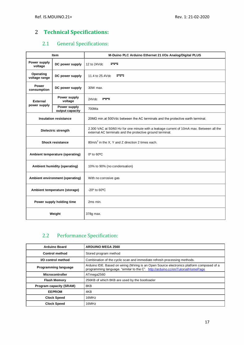
Technical Specifications: 2
2.1 General Specifications:
Item M-Duino PLC Arduino Ethernet 21 I/Os Analog/Digital PLUS
Power supply voltage
DC power supply 12 to 24Vdc
Operating voltage range
DC power supply 11.4 to 25.4Vdc
Power consumption
DC power supply 30W max.
External
power supply
Power supply voltage
24Vdc
Power supply
output capacity 700Ma
Insulation resistance 20MΩ min.at 500Vdc between the AC terminals and the protective earth terminal.
Dielectric strength 2.300 VAC at 50/60 Hz for one minute with a leakage current of 10mA max. Between all the external AC terminals and the protective ground terminal.
Shock resistance 80m/s2 in the X, Y and Z direction 2 times each.
Ambient temperature (operating) 0º to 60ºC
Ambient humidity (operating) 10% to 90% (no condensation)
Ambient environment (operating) With no corrosive gas
Ambient temperature (storage) -20º to 60ºC
Power supply holding time 2ms min.
Weight 378g max.
2.2 Performance Specification:
Arduino Board ARDUINO MEGA 2560
Control method Stored program method
I/O control method Combination of the cyclic scan and immediate refresh processing methods.
Programming language Arduino IDE. Based on wiring (Wiring is an Open Source electronics platform composed of a
programming language. “similar to the C”. http://arduino.cc/en/Tutorial/HomePage
Microcontroller ATmega2560
Flash Memory 256KB of which 8KB are used by the bootloader
Program capacity (SRAM) 8KB
EEPROM 4KB
Clock Speed 16MHz
Clock Speed 16MHz
Ref. IS.MDUINO.21+ Rev. 1: 21-02-2020
18
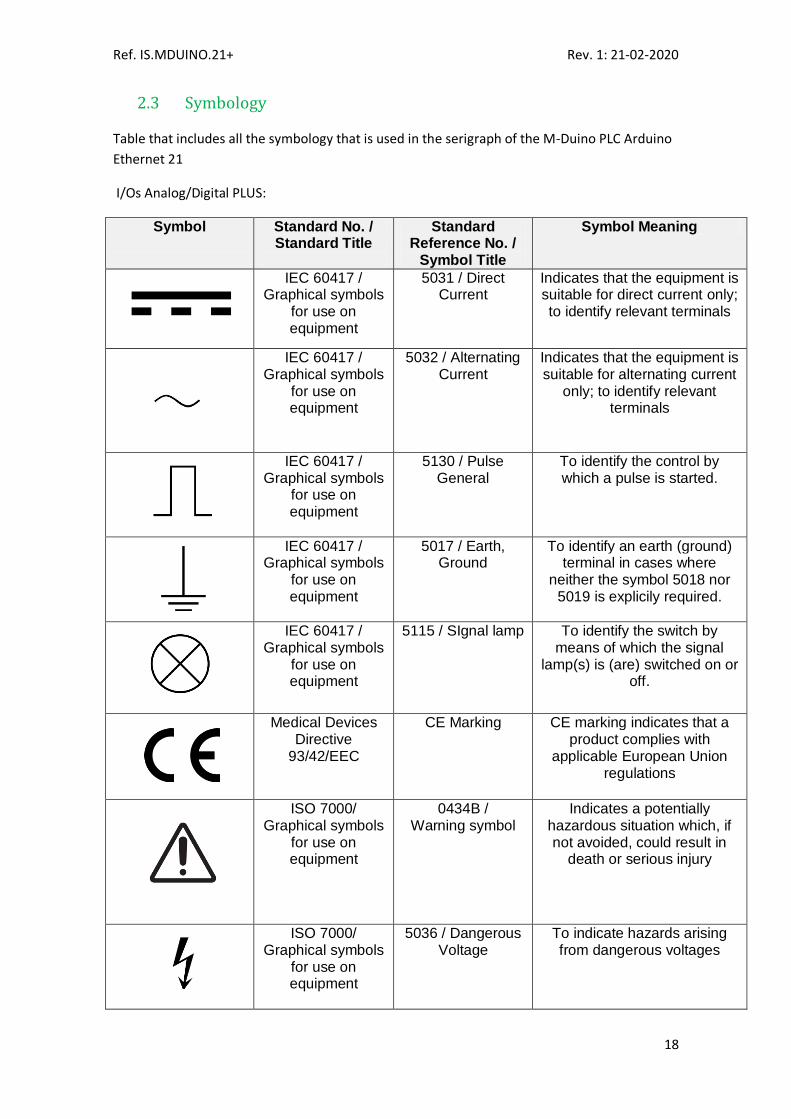
2.3 Symbology
Table that includes all the symbology that is used in the serigraph of the M-Duino PLC Arduino
Ethernet 21
I/Os Analog/Digital PLUS:
Symbol
Standard No. / Standard Title
Standard Reference No. /
Symbol Title
Symbol Meaning
IEC 60417 / Graphical symbols
for use on equipment
5031 / Direct Current
Indicates that the equipment is suitable for direct current only; to identify relevant terminals
IEC 60417 / Graphical symbols
for use on equipment
5032 / Alternating Current
Indicates that the equipment is suitable for alternating current
only; to identify relevant terminals
IEC 60417 / Graphical symbols
for use on equipment
5130 / Pulse General
To identify the control by which a pulse is started.
IEC 60417 / Graphical symbols
for use on equipment
5017 / Earth, Ground
To identify an earth (ground) terminal in cases where
neither the symbol 5018 nor 5019 is explicily required.
IEC 60417 / Graphical symbols
for use on equipment
5115 / SIgnal lamp To identify the switch by means of which the signal
lamp(s) is (are) switched on or off.
Medical Devices Directive
93/42/EEC
CE Marking CE marking indicates that a product complies with
applicable European Union regulations
ISO 7000/ Graphical symbols
for use on equipment
0434B / Warning symbol
Indicates a potentially hazardous situation which, if not avoided, could result in
death or serious injury
ISO 7000/ Graphical symbols
for use on equipment
5036 / Dangerous Voltage
To indicate hazards arising from dangerous voltages

Ref. IS.MDUINO.21+ Rev. 1: 21-02-2020
19
Precautions 3
Read this manual before attempting to use the M-Duino PLC Arduino Ethernet 21 I/Os Analog/Digital PLUS and follow its descriptions for reference during operation.
3.1 Arduino Board
The M-Duino 21 I/Os PLUS PLCs include Arduino Mega Board as controller.
3.2 Intended Audience
This manual is intended for technicians, which must have knowledge on electrical systems.
3.3 General Precautions
The user must operate M-Duino according to the performance specifications described in this
manual.
Before using M-Duino under different conditions from what has been specified in this manual
or integrating M-Duino to nuclear control systems, railroad systems, aviation systems, vehicles,
combustion systems, medical equipment, amusement machines, safety equipment and other
systems, machines, and equipment that may have a serious influence on lives and property if
used improperly, consult your INDUSTRIAL SHIELDS representative. Ensure that the rating and
performance characteristics of M-Duino are sufficient for the systems, machines, and
equipment, and be sure to provide the systems, machines, and equipment double safety
mechanisms. This manual provides information for programming and operating the M-Duino.
Software interface 4
Industrial Shields PLC are programmed using Arduino IDE, which is a software based on the C
language. They can also be programmed using directly C but it is much easier working with
Arduino IDE as it provides lots of libraries that helps in the programming.
Industrial Shields provides boards for programming the PLCs much easier. Basically it is no
needed to define the pins and if that pins are inputs or outputs. Everything is set up
automatically if using the boards.
In order to install Industrial Shields boards, these are the steps that must be followed.
Requirements:
Arduino IDE 1.8.0 or above (better to have always the latest version).
Ref. IS.MDUINO.21+ Rev. 1: 21-02-2020
20
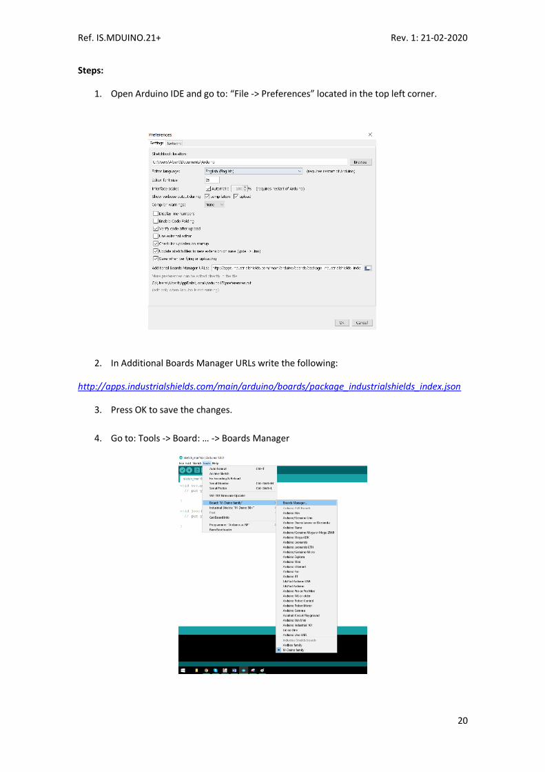
Steps:
1. Open Arduino IDE and go to: “File -> Preferences” located in the top left corner.
2. In Additional Boards Manager URLs write the following:
http://apps.industrialshields.com/main/arduino/boards/package_industrialshields_index.json
3. Press OK to save the changes.
4. Go to: Tools -> Board: … -> Boards Manager

Ref. IS.MDUINO.21+ Rev. 1: 21-02-2020
21
5. Search for “industrialshields” on the browser.
6. Click install (selecting the latest version).
Following these steps you will be able to see now the Industrial Shields Boards:

Ref. IS.MDUINO.21+ Rev. 1: 21-02-2020
22
Once it is selected M-Duino Family, an extra option will appear on Tools:
There, it can be selected the exact model for every family.
Also there are some examples of programming in File -> Examples -> M-Duino Family.
Furthermore there are some extra libraries that can be found in Industrial Shields github.
https://github.com/IndustrialShields/
How to connect PLC Arduino to PC 5
- Connect USB port from PLC to PC.
NOTE: M-Duino 21 I/Os PLUS uses USB-B cable.
- Open Arduino IDE interface:
- Select Industrial Shields boards -> M-Duino Family

Ref. IS.MDUINO.21+ Rev. 1: 21-02-2020
23
- Select the correct M-Duino Board (M-Duino 21+).
- Select correct port.

Ref. IS.MDUINO.21+ Rev. 1: 21-02-2020
24
How to connect PLC to power supply 6
- M-Duino 21 I/Os PLUS PLC is 12-24Vdc supplied. IMPORTANT: The polarity IS NOT
REVERSAL!
- Make sure that the live and GND connector of the power supply match the PLC.
- Make sure that the power supply mains output is not higher than 24Vdc.
- Suggested power suppliers
The standard, Part 1 of IEC 61010, sets the general safety requirements for the following types
of electrical devices and their accessories, regardless of where use of the device is intended.
The equipment must be powered from an external power source in accordance with IEC
61010-1, whose output is MBTS and is limited in power according to section 9.4 of IEC 61010-
1.
WARINING: Once the equipment is installed inside an electrical cabinet, the MTBS cables of
the equipment must be separated from the dangerous voltage cables.
Compact DIN rail power supply. Assembled on 35mm
DIN Rail:
-12Vdc / 24Vdc
-2.5A
-30W
Industrial Shields power supplies provide parallel
operation, overvoltage protection, and overcurrent
protection. There is a LED inductor for power status,
the power supply is certified according to UL.

Ref. IS.MDUINO.21+ Rev. 1: 21-02-2020
25
M-Duino 21 I/Os PLUS Pinout 7
7.1 A Zone connection
SS: Chip Select pins. These pins can act as TTL, so they can work for the Chip Select pin of any device.
Base (common unit)
A Zone
M-D
uin
o
Co
nn
ecto
r
Ard
uin
o P
in
Functio
n
SCL SDA RX0 TX0 RX1 TX1 TX RX Z- Y+ B- A+
PIN3 50 SO 51 SI
52 SCK
Reset Vin5 PIN2 GND GND
24Vdc
21 20
1 0
19
18 16
17 -
- -
- 3
50 51
52
Reset Vin5
2 -
-
I2C/SS I2C/SS RX0/SS TX0/SS RX1/SS TX1/SS
RX2(serial 2) TX2(serial 2)
RS485 RS485 RS485 RS485
Arduino Pin SPI SPI SPI
SPI 5V
Arduino Pin Gnd Gnd
Power Supply
Base (common unit)
A Zone
M-D
uin
o
Co
nn
ecto
r
Ard
uin
o P
in
Functio
n
AREF IOREF2 IOREF1
7Vdc GND
3.3Vdc GND 5Vdc GND
AREF
IOREF2 IOREF1
7Vdc GND
3.3Vdc GND
5Vdc GND
Arduino PIN Arduino PIN Arduino PIN
- GND
Arduino PIN GND
- GND
Configuration Switch* (see section 8 for configuring the communications. Enabling communications disables some I/Os) Communication Pins Power supply connectors (24Vdc – GND)
Ref. IS.MDUINO.21+ Rev. 1: 21-02-2020
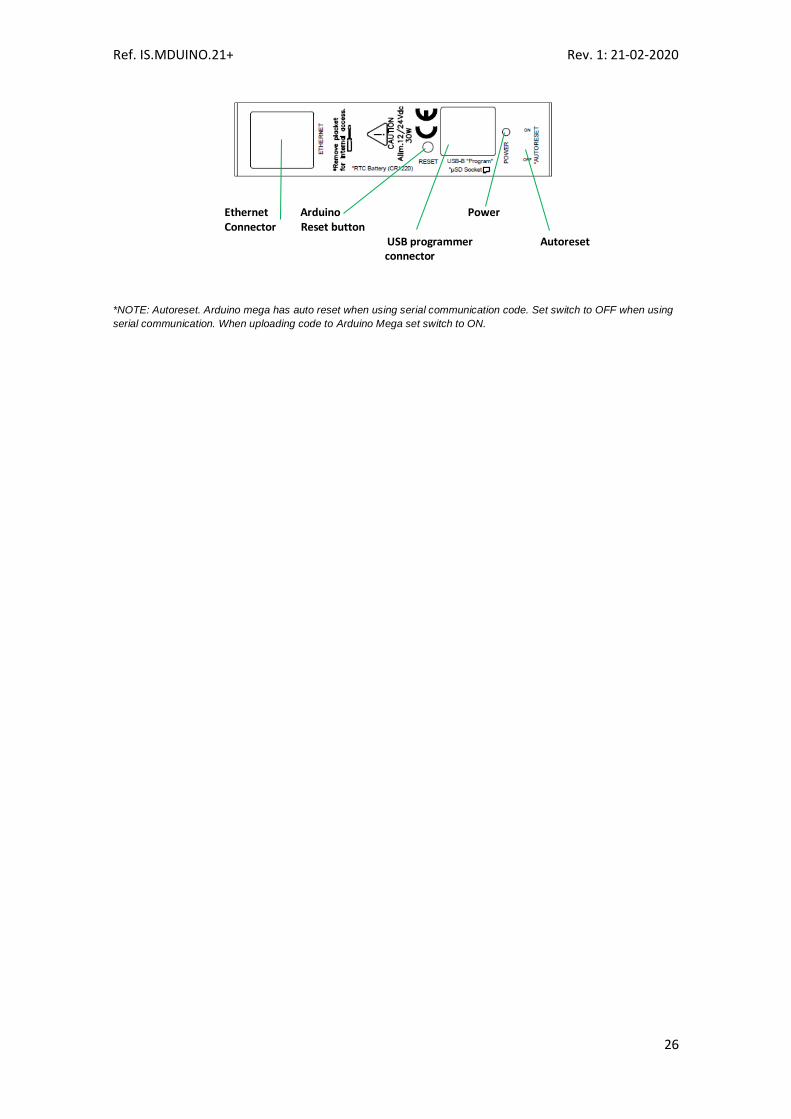
26
*NOTE: Autoreset. Arduino mega has auto reset when using serial communication code. Set switch to OFF when using
serial communication. When uploading code to Arduino Mega set switch to ON.
Ethernet Arduino Power Connector Reset button USB programmer Autoreset connector

Ref. IS.MDUINO.21+ Rev. 1: 21-02-2020
27
7.2 B Zone (Analog Shield)
1 See section 8 to select suitable switch configuration for enable these connections.
B Zone
M-D
uin
o
Co
nn
ecto
r
Ard
uin
o P
in
Functio
n
I0.12 I0.11 I0.10 I0.9 I0.8 I0.7
(-)I0.6/INT1 I0.6/INT1
1
(-)I0.5/INT0 I0.5/INT0
1
(-)I0.4 I0.4
(-)I0.3 I0.3
(-)I0.2 I0.2
(-)I0.1
I0.1 (-)I0.0 I0.0
59
58
57 56
55 54
- 3
- 2
- 26
- 25
-
24 -
23 -
22
Analog/ Digital In Analog/ Digital In Analog/ Digital In Analog/ Digital In Analog/ Digital In Analog/ Digital In
GND I0.6 Interrupt 1 In
GND I0.5 Interrupt 0 In
GND I0.4 Digital Input GND I0.3
Digital Input GND I0.2
Digital Input GND I0.1
Digital Input GND I0.0
Digital Input
B Zone
M-D
uin
o
Co
nn
ecto
r
Ard
uin
o P
in
Functio
n
GND A0.7
1
A0.61
A0.51
Q/Vdc COM(-) Q0.7
1
Q0.61
Q0.51
Q0.4 Q0.3 Q0.2 Q0.1
Q0.0
GND 6
5 4
- -
6
5 4
40 39
38 37
36
GND Analog Out Analog Out Analog Out
External Isolated Out Vdc External Isolated Out GND
Digital/PWM Out Digital/PWM Out Digital/PWM Out
Digital Out Digital Out Digital Out Digital Out
Digital Out
Led indicator I/Os state
Analog/Digital Inputs Interrupt Inputs (isolated) Digital Inputs (isolated)
Configuration Switch* (see section 8 to select the correct configuration for outputs). Analog Outputs Voltage Supply/Reference for Digital/PWM Outputs (isolated) PWM/Digital Outputs
Top Zone

Ref. IS.MDUINO.21+ Rev. 1: 21-02-2020
28
Switch Configuration 8
8.1 A Zone: Communications
4. SCL/NC: Always at OFF Position! Switch has to be OFF position to enable SCL, never ON
because in this position is NC (Not Connected).
3. SDA/NC: Always at OFF Position! Switch has to be OFF position to enable SDA, never ON
because in this position is NC (Not Connected).
2. RX1/NC: Always at OFF Position! Switch has to be OFF position to enable RX1 never ON
because in this position is NC (Not Connected).
1. TX1/NC: Always at OFF Position! Switch has to be OFF position to enable TX1, never ON
because in this position is NC (Not Connected).
Switch
ON OFF
D ZONE
SCL/I2.6 NC SCL
SDA/I2.5 NC SDA
C ZONE
RX1/I1.6 NC RX1
TX1/I1.5 NC TX1
B ZONE
Pin 3/I0.6 I0.6 Pin 3
Pin 2/I0.5 I0.5 Pin 2
uSD & RS-485
D53(SD) NC SD
FD RS-485 HD HD FD

Ref. IS.MDUINO.21+ Rev. 1: 21-02-2020
29
4. Pin 3/I0.6: Choosing between Pin 3 or the input I0.6. If this switch is ON, it enables the I0.6
input and disables the Pin 3. If this switch is OFF, it enables Pin 3 and disables I0.6.
3. Pin 2/I0.5: Choosing between Pin 2 or the input I0.5. If this switch is ON, it enables the I0.5
input and disables the Pin 2. If this switch is OFF, it enables Pin 2 and disables I0.5.
2. D53 (SD): Always at OFF Position! Switch has to be OFF position to enable the Chip Select of
the microSD card, never ON because in this position is NC (Not Connected).
1. FD RS-485 HD: Choosing between FD or HF. If this switch is ON, it enables the Half Duplex
(HD) option and disables the FD. If this switch is OFF, it enables Full Duplex (FD) and disables
HD.
1. RTC SDA: This switch enables the communication to communicate with the RTC using
I2C. Having this switch in ON mode it actives this communication, whereas if it is in
OFF mode it disables the I2C to reach the RTC.
2. RTC SCL: This switch enables the communication to communicate with the RTC using
I2C. Having this switch in ON mode it actives this communication, whereas if it is in
OFF mode it disables the I2C to reach the RTC.
3. NC: Not connected. This switch is not connected to anything, it doesn’t matter if it is in
ON mode or OFF mode.
4. NC: Not connected. This switch is not connected to anything, it doesn’t matter if it is in
ON mode or OFF mode.
LEFT ZONE
SWITCH ON OFF
NC - -
NC - -
RTC SCL RTC -
RTC SDA RTC -

Ref. IS.MDUINO.21+ Rev. 1: 21-02-2020
30
8.2 B, C & D Zone Swithces
For the Analog Shield if a switch is set to ON, it can only act as Digital Output. If it is set to OFF
it can only act as an Analog Output.
If it is desired to use a Digital Output the pin must be set to ON and the pin that will provide
this digital output is represented with QX.X, being X any number of the tables above.
If it is desired to use an Analog Output the pin must be set to OFF and the pin that will provide
this analog output is represented with AX.X, being X any number of the tables above.
For the Relay Shield if a switch is set to ON, it can only act as Digital Output. If it is set to OFF it
can only act as an Analog Output.
If it is desired to use a Digital Output the pin must be set to ON and the pin that will provide
this digital output is represented with QX.X, being X any number of the tables above.
If it is desired to use an Analog Output the pin must be set to OFF and the pin that will provide
this analog output is represented with AX.X, being X any number of the tables above.
B ZONE
SWITCH ON OFF
NC - -
Q0.7 Q0.7 A0.7
Q0.6 Q0.6 A0.6
Q0.5 Q0.5 A0.5
C ZONE
SWITCH ON OFF
NC - -
Q1.7 Q1.7 A1.7
Q1.6 Q1.6 A1.6
Q1.5 Q1.5 A1.5
D ZONE
SWITCH ON OFF
NC - -
Q2.7 - -
Q2.6 Q2.6 A2.6
Q2.5 Q2.5 A2.5

Ref. IS.MDUINO.21+ Rev. 1: 21-02-2020
31
M-Duino Arduino I/Os 5V pins 9
The M-Duino has some of the Mega board pins available. These pins can be programmed
according to Arduino features such as I/Os operating at 5V or any additional features present
in the pins (for example I2C communication in pins SCL and SDA). As this pins are directly
connected to the Arduino Mega board they are not as well protect as the normal inputs. These
pins are mainly meant to be used as prototyping.
The Arduino board available pins are summarized in the table below. In order to access some
of these pins the configuration switch must be set to OFF position (see section 8) and some
extra considerations must be taken in consideration when using these pins.
*IMPORTANT: Do not connect the terminals in the chart above to voltages higher than 5V.
These terminals provide direct access to the Mega board.
A part from the switch configuration there are some special conditions depending on these 5V.
Now it is going to be shown the considerations to operate with these pins.
9.1 I2C pins – SDA/SCL
The I2C protocol is meant to work in a pull-up configuration. A pull-up configuration means
that when the pin is at rest (nothing connected to it) it always reads a HIGH value. In this case
it reads 5V when nothing is connected. The pull-up configuration is stablished by default in
these pins.
If it is meant to work them as a GPIO at 5V, it has to be considered that they are pull-up
inputs.
*IMPORTANT: I2.5 & I2.6 are not pull-up inputs although they are referred to the I2C pins
(switch configuration). There is a “reverse pull-up circuit “that is stablished in order to have the
same behaviour as the other inputs.
9.2 Serial 0 – RX0/TX0
The Serial0 protocol can work also as a 5V pin. These pins should be used ultimately, only in
case that all the 5V pins are already performing a function. This is because they are shared
with the USB interface. If using these pins, the USB communication cannot be working at the
same time. When the PLC is not installed, the USB communication is normally required for
debugging, uploading and intercommunicating with the Ethernet controller. If using both
interfaces at the same time the Arduino board will get blocked.
M-Duino terminal Arduino pin Enable Arduino pin
SCL 21 Communication switch: OFF
SDA 20 Communication switch OFF
RX0 0
TX0 1
RX1 19 Communication switch: OFF
TX1 18 Communication switch: OFF
MISO 50
MOSI 51
SCK 52
Pin 3 3 Communication switch: OFF
Pin 2 2 Communication switch: OFF

Ref. IS.MDUINO.21+ Rev. 1: 21-02-2020
32
These pins are not stablished with a pull-up or a pull-down configuration. The state of these
pins is unknown. If these pins must be used, they require a pull-up or a pull-down
configuration. The Arduino board allows the pins to be set in a pull-up configuration. If not it
must be stablished an external pull-up or pull-down circuit in order to correctly work with
these pins.
9.3 Serial 1 – RX1/TX1
These pins are only referred to the inputs I1.5/I1.6. If the switch configuration is in OFF
position the pins RX1/TX1 will be available. If not using the Serial 1 interface these pins can
work as digital, either input or output.
These pins are not stablished with a pull-up or a pull-down configuration. The state of these
pins is unknown. If these pins must be used, they require a pull-up or a pull-down
configuration. The Arduino board allows the pins to be set in a pull-up configuration. If not it
must be stablished an external pull-up or pull-down circuit in order to correctly work with
these pins.
9.4 SPI – MISO/MOSI/SCK
These pins can only work as a 5V pins if the Ethernet protocol is not going to be used. As the
Ethernet protocol uses the SPI to communicate with the Arduino board, both behaviours
cannot happen at the same time as the Ethernet would not work.
These pins are not stablished with a pull-up or a pull-down configuration. The state of these
pins is unknown. If these pins must be used, they require a pull-up or a pull-down
configuration. The Arduino board allows the pins to be set in a pull-up configuration. If not it
must be stablished an external pull-up or pull-down circuit in order to correctly work with
these pins.
9.5 Pin 2/Pin 3
These pins are only referred to the inputs I0.5/I0.6. If the switch configuration is in OFF
position the pins Pin 2/Pin 3 will be available.
These pins are not stablished with a pull-up or a pull-down configuration. The state of these
pins is unknown. If these pins must be used, they require a pull-up or a pull-down
configuration. The Arduino board allows the pins to be set in a pull-up configuration. If not it
must be stablished an external pull-up or pull-down circuit in order to correctly work with
these pins.

Ref. IS.MDUINO.21+ Rev. 1: 21-02-2020
33
A Zone Features: Communications & RTC & uSD 10
10.1 RS-232
The Arduino Mega function code to access the RS-232 port in the M-Duino is Serial2 (pins 16
and 17 of the Arduino Mega).
For the RS-232 communication protocol there isn’t any switch that affects it. So it does not
matter the configuration of the switches to implement a RS-232 communication.
Using the boards of Industrial Shields, there is a library that simplifies the RS-232
implementation.
10.2 RS-485
For RS485 communication protocol the defined Arduino Mega pins are showed in the chart
below.
Function Arduino Pin
DI 14
RO 15
RE 11
DE 46
For the RS-485 communication protocol there is only one switch that affects in this
communication. The RS-485 protocol will be always enabled, the only switch that affects is the
one called “FD rs-485 HD” (See Section 8). This switch makes the choosing between RS-485
Half Duplex or RS-485 Full Duplex (RS-422).
Using the boards of Industrial Shields, there is a library that simplifies the RS-485
implementation.
10.3 I2C
I2C communication DOES NOT REQUIRE a pull-up resistor for the M-Duino 21 I/Os PLUS. The
pull-up resistor is already implemented in the PCB.
I2C communication is configured by switches, so the switches must be configured in order to
enable the I2C communication.
Switch ON OFF
D ZONE
SCL/I2.6 I2.6 SCL
SDA/I2.5 I2.5 SDA

Ref. IS.MDUINO.21+ Rev. 1: 21-02-2020
34
To enable I2C the switches SCL/I2.6 & SDA/I2.5 must be set to OFF mode. In this mode the
inputs are totally disabled and the I2C is now enabled.
Industrial Shields does not provide any library to implement the I2C as it can be used the
standard library of Arduino called Wire.
10.4 SPI
The M-Duino pins used for the SPI bus are summarized in the table below. For SPI bus MISO,
MOSI and CLOCK pins are common to all the connected devices to the M-Duino, conversely,
each of the connected devices will have a single and dedicated SS pin.
Function M-Duino connection Mega board pin
MISO 50 S0 50
MOSI 51 SI 51
CLOCK 52 SCK 52
Reset Reset Reset
SS SCL/SDA/RX0/TX0/RX1/TX1/RX3/TX3/Pin2/Pin3 21/20/1/0/19/18/15/14/2/3
Check the switch configuration at section 8 to enable SS pins.
10.5 TTL
M-Duino has two TTL ports, RX0/TX0, RX1/TX1. TTL0 is accessed with the function Serial (pins 0
and 1 of the Arduino Mega). TTL1 is accessed with the function Serial1 (pins 18 and 19 of the
Arduino Mega).
In order to use the TTL pins the configuration of the switches have to be the following one:
If the switches RX1/I1.6(I1.1) & TX1/I1.5(I1.0) are in OFF mode, the RX1/TX1 will be enabled. In
order to use TTL3 these switches must be in OFF mode.
10.6 Ethernet
M-Duino Ethernet port controller is based on w5500 IC, which is the compatible IC compatible
with Arduino Ethernet2 Shield libraries. All Ethernet shield Arduino libraries are compatible
with the M-Duino. In the M-Duino, W5500 IC communicates to the Mega board via SPI bus (SS
Arduino Mega pin 10).
Switch Analog Shield
ON OFF
C ZONE
RX1/I1.6 I1.6 RX1
TX1/I1.5 I1.5 TX1
Ref. IS.MDUINO.21+ Rev. 1: 21-02-2020
35
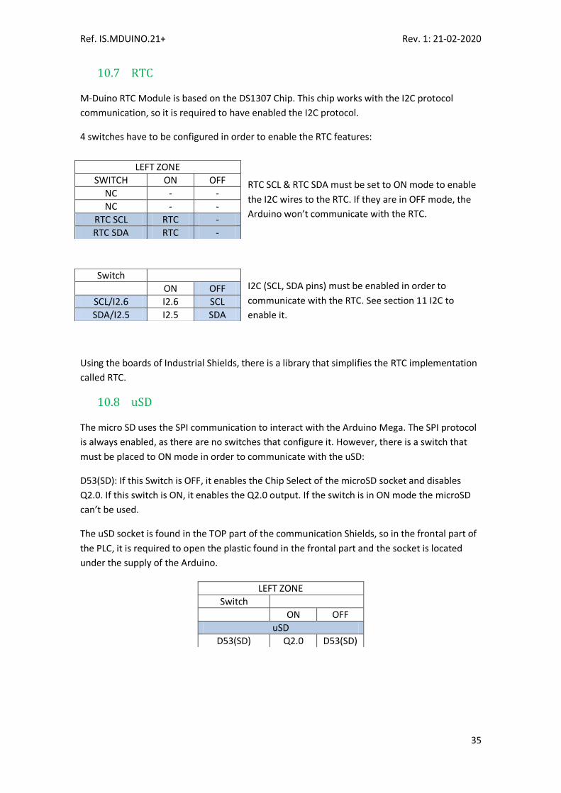
10.7 RTC
M-Duino RTC Module is based on the DS1307 Chip. This chip works with the I2C protocol
communication, so it is required to have enabled the I2C protocol.
4 switches have to be configured in order to enable the RTC features:
RTC SCL & RTC SDA must be set to ON mode to enable
the I2C wires to the RTC. If they are in OFF mode, the
Arduino won’t communicate with the RTC.
I2C (SCL, SDA pins) must be enabled in order to
communicate with the RTC. See section 11 I2C to
enable it.
Using the boards of Industrial Shields, there is a library that simplifies the RTC implementation
called RTC.
10.8 uSD
The micro SD uses the SPI communication to interact with the Arduino Mega. The SPI protocol
is always enabled, as there are no switches that configure it. However, there is a switch that
must be placed to ON mode in order to communicate with the uSD:
D53(SD): If this Switch is OFF, it enables the Chip Select of the microSD socket and disables
Q2.0. If this switch is ON, it enables the Q2.0 output. If the switch is in ON mode the microSD
can’t be used.
The uSD socket is found in the TOP part of the communication Shields, so in the frontal part of
the PLC, it is required to open the plastic found in the frontal part and the socket is located
under the supply of the Arduino.
LEFT ZONE
SWITCH ON OFF
NC - -
NC - -
RTC SCL RTC -
RTC SDA RTC -
Switch
ON OFF
SCL/I2.6 I2.6 SCL
SDA/I2.5 I2.5 SDA
LEFT ZONE
Switch
ON OFF
uSD
D53(SD) Q2.0 D53(SD)

Ref. IS.MDUINO.21+ Rev. 1: 21-02-2020
36
Using the boards of Industrial Shields, there is a library that simplifies the uSD implementation
called SD. It is the same as the Arduino library, with the only modification of using the pin 53 to
select the Chip Select of the uSD chip.
Verify that the CPU is not actively running a process before inserting the memory card.
Inserting a memory card will cause the CPU to go to STOP mode, which could affect the
operation of an online process or machine. Unexpected operation of a process or machine
could result in death or injury to personnel and/or property damage. Before inserting a
memory card, always ensure that the CPU is offline and in a safe state.
Vérifiez que le processeur n'exécute pas activement un processus avant d'insérer la
carte mémoire.
Si vous insérez une carte mémoire, la CPU passe en mode STOP, ce qui peut affecter le
fonctionnement d'un processus ou d'une machine en ligne. Le fonctionnement inattendu d'un
processus ou d'une machine peut entraîner la mort ou des blessures corporelles et / ou des
dégâts matériels. Avant d'insérer une carte mémoire, assurez-vous toujours que la CPU est
hors ligne et en sécurité.

Ref. IS.MDUINO.21+ Rev. 1: 21-02-2020
37
Instructions for interconnection between Industrial Shields 11
controllers
11.1 RS-232 Communication:
11.2 RS-485 Communication:
11.2.1.1 Half Duplex
11.2.2 Full Duplex

Ref. IS.MDUINO.21+ Rev. 1: 21-02-2020
38
11.3 Ethernet
For an Ethernet communication between Industrial Shields equipment a SFTP CAT-6 Ethernet
crossover cable must be used.

Ref. IS.MDUINO.21+ Rev. 1: 21-02-2020
39
I/O technical details: 12
Digital Output Waveform:
Digital Out-put Turn-off:
PWM Waveform:

Ref. IS.MDUINO.21+ Rev. 1: 21-02-2020
40
Analog Out Turn On:
Analog Out Turn-Off:
Analog /Digital input Turn-on:

Ref. IS.MDUINO.21+ Rev. 1: 21-02-2020
41
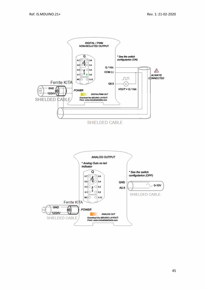
Typical Connections 13
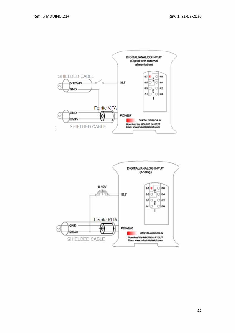
Ref. IS.MDUINO.21+ Rev. 1: 21-02-2020
42

Ref. IS.MDUINO.21+ Rev. 1: 21-02-2020
43
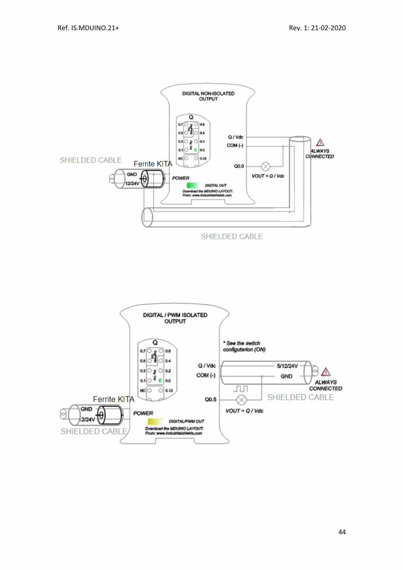
Ref. IS.MDUINO.21+ Rev. 1: 21-02-2020
44
Ref. IS.MDUINO.21+ Rev. 1: 21-02-2020
45
Ref. IS.MDUINO.21+ Rev. 1: 21-02-2020
46
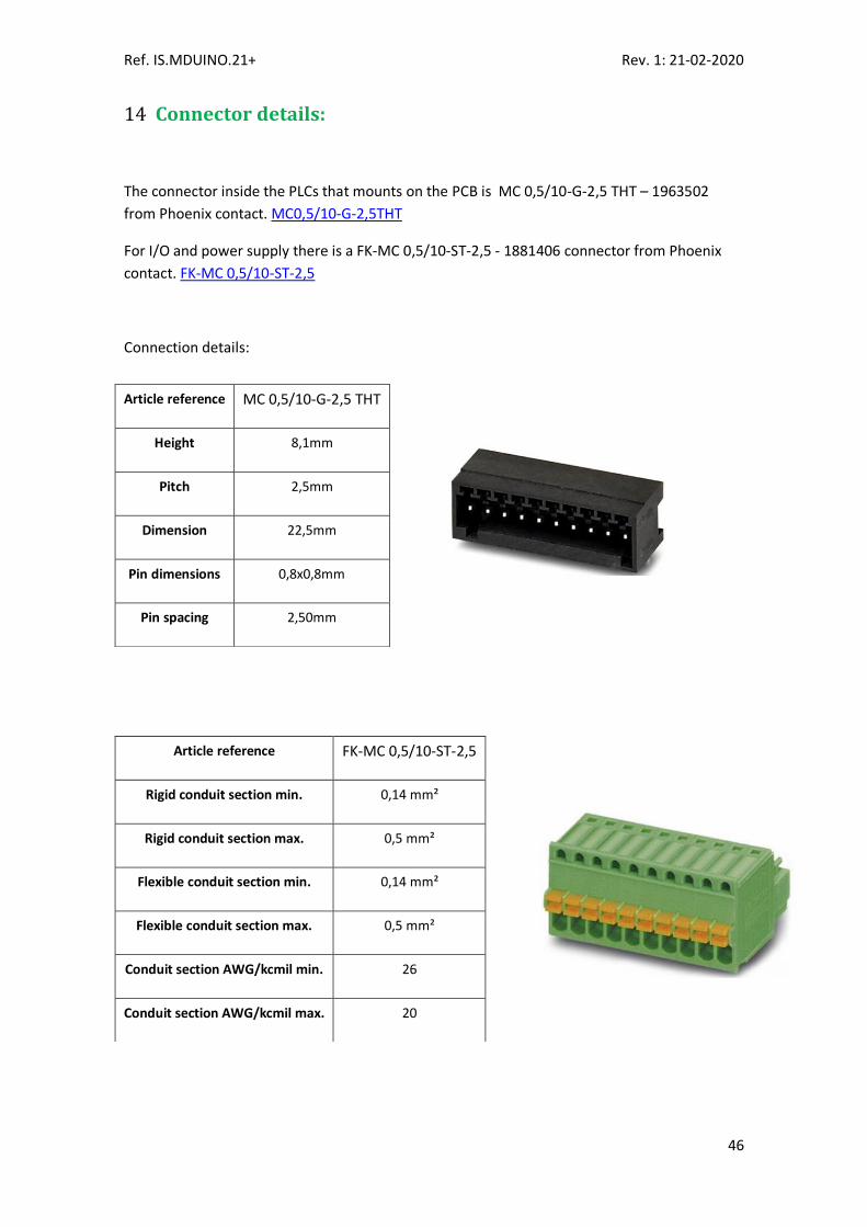
Connector details: 14
The connector inside the PLCs that mounts on the PCB is MC 0,5/10-G-2,5 THT – 1963502
from Phoenix contact. MC0,5/10-G-2,5THT
For I/O and power supply there is a FK-MC 0,5/10-ST-2,5 - 1881406 connector from Phoenix
contact. FK-MC 0,5/10-ST-2,5
Connection details:
Article reference MC 0,5/10-G-2,5 THT
Height 8,1mm
Pitch 2,5mm
Dimension 22,5mm
Pin dimensions 0,8x0,8mm
Pin spacing 2,50mm
Article reference FK-MC 0,5/10-ST-2,5
Rigid conduit section min. 0,14 mm²
Rigid conduit section max. 0,5 mm²
Flexible conduit section min. 0,14 mm²
Flexible conduit section max. 0,5 mm²
Conduit section AWG/kcmil min. 26
Conduit section AWG/kcmil max. 20

Ref. IS.MDUINO.21+ Rev. 1: 21-02-2020
47
Mechanical Characteristics 15
- Dimension M-Duino 21 I/Os PLUS:
- DIN Rail mounting
For optimal operation of the product, it must be located in an electrical cabinet with IK08
mechanical protection. The minimum IP protection degree required is IP56.

Ref. IS.MDUINO.21+ Rev. 1: 21-02-2020
48
Installation and Maintenance 16
Notes for installation:
- The installation position should be free from the following: dust or oil smoke, conductive dust, corrosive or flammable gas, high temperature, condensation, and rain.
- Besides, vibration and impact also affect the PLC normal operation and shorten its lifespan; electric shock, fire or misact also damages the product. During drilling or wiring, prevent the metal particles or wire segments from falling into the PLC casing, which may cause fire, fault or misact.
- After the PLC installation, clean the ventilation duct to prevent blocking, which may cause bad ventilation, or even fire, faults or misact.
- Do not online connect, plug or unplug cables, which is apt to cause electric shock or damage the circuit. Installation and wire connection must be firm and reliable. Poor connection could cause misact.
- Use shielded twisted pair for the I/O of high frequency signal and analog signal to improve system IMS.
The installation environment should be free from dust, oil smoke, conductive particle, corrosive or flammable gases, high temperature, condensation, and rain. Besides, vibration and impact also affect the PLC normal operation and shorten its lifespan. It is recommended to install the PLC, together with the matching switches and contactors, in a dedicated electric cabinet and keep the cabinet ventilated. If the location has high ambient temperature or heat generating equipment nearby, install forced convection devices on top or sides of the cabinet to avoid over-temperature. During drilling or wiring, prevent the metal particles or wire segments from falling into the PLC casing, which may cause fire, fault or misact. After the PLC installation, clean the ventilation duct to prevent blocking, which may cause bad ventilation, or even fire, faults or misact. The only way to disconnect the equipment from the electrical network is by removing the connectors that feed the equipment. Once installed in the electrical cabinet it is very important to ensure the power connectors for proper operation.
Separate the M-Duino 21 I/Os PLUS from heat, high voltaje and eletrical noise: Always separate the devices that generate high voltage and high electrical noise from the M-Duino 21 I/Os PLUS. When configuring the layout of the M-Duino 21 I/Os PLUS inside your panel, consider the heat-generating devices and locate the electronic-type devices in the cooler areas of your cabinet. Reducing the exposure to a high-temperature environment will extend the operating life of any electronic device. Consider also the routing of the wiring for the devices in the electric cabinet. Avoid placing low-voltage signal wires and communications cables in the same tray with AC power wiring and highenergy, rapidly-switched DC wiring.

Ref. IS.MDUINO.21+ Rev. 1: 21-02-2020
49
Provide adequate clearance for cooling and wiring M-Duino 21 I/Os PLUS. Is designed for natural convection cooling. For proper cooling, you must provide a clearance of at least 25 cm above and below the devices. Also, allow at least 25 cm of depth between the front of the modules and the inside of the enclosure.
Notes for maintenance: A well-planned and executed maintenance program is essential to the satisfactory operation of solid-state electrical equipment. The kind and frequency of the maintenance operation will vary with the kind and complexity of the equipment as well as with the nature of the operating conditions. Maintenance recommendations of the manufacturer or appropriate product standards should be followed. The following factors should be considered when formulating a maintenance program:
- Maintenance must be performed by qualified personnel familiar with the construction, operation, and hazards involved with the control.
- Maintenance should be performed with the control out of operation and disconnected from all sources of power.
- Care should be taken when servicing electrostatic sensitive components. The manufacturer's recommendations for these components should be followed.
- Ventilation passages should be kept open. If the equipment depends upon auxiliary cooling, e.g., air, water, or oil, periodic inspection (with filter replacement when necessary) should be made of these systems.
- The means employed for grounding or insulating the equipment from ground should be checked to assure its integrity.
- Accumulations of dust and dirt on all parts, including on semiconductor heat sinks, should be removed according to the manufacturer's instructions, if provided; otherwise, the manufacturer should be consulted. Care must be taken to avoid damaging any delicate components and to avoid displacing dust, dirt, or debris in a way that permits it to enter or settle into parts of the control equipment.
- Enclosures should be inspected for evidence of deterioration. Accumulated dust and dirt should be removed from the top of the enclosures before opening doors or removing covers.
- Certain hazardous materials removed as part of maintenance or repair procedure (e.g., polychlorinated biphenyls (PCBs) found in some liquidfilled capacitors) must be disposed of as described in Federal regulations.
Safety rules for maintenance personnel
Consider the following steps to follow. A false manoeuvre could be the cause of an accident or material damage. Do not disassemble or modify the modules. This could lead to breakdowns or malfunctions and could lead to injuries or fire.
- All types of radio communication devices, including mobile phones and personal handy-phone systems (PHS), must be kept more than 25cm away from the PLC in all directions. Failure to observe this precaution exposes malfunctions caused by excess of temperature. - Disconnect the external power supply of the system (on all phases) before connecting or disconnecting a module. Failure to observe this precaution may cause faults or malfunctions of the module.

Ref. IS.MDUINO.21+ Rev. 1: 21-02-2020
50
- Tighten the screws of the terminal ports and the screws of the connectors within the prescribed tightening torque. Insufficient tightening can lead to loose parts or wires and cause malfunctions. Excessive tightening can damage the screws and / or the module, with the risk of falling, short circuits and malfunctions. - Before handling a module, dispose of the electrostatic charge accumulated by the human body by touching a suitable conductive object. Failure to observe this precaution may cause faults or malfunctions of the module.
Repair note:
If the equipment is suitable to be repaired, it must be verified that the equipment remains in a safe state after repair.
Ref. IS.MDUINO.21+ Rev. 1: 21-02-2020
51
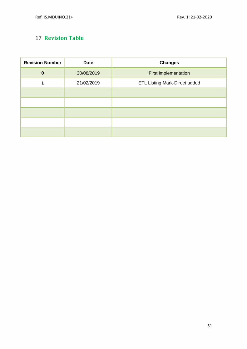
Revision Table 17
Revision Number Date Changes
0 30/08/2019 First implementation
1 21/02/2019 ETL Listing Mark-Direct added

Ref. IS.MDUINO.21+ Rev. 1: 21-02-2020
52
About Industrial Shields: Direction: Fàbrica del Pont, 1-11
Zip/Postal Code: 08272
City: Sant Fruitós de Bages (Barcelona)
Country: Spain
Telephone: (+34) 938 760 191 / (+34) 635 693 611
Mail: [email protected]