M d li C k I t itModeling Caprock Integrity: Assessment ... · situ fluid composition (e g pH...
45
M d li C kI t it Modeling Caprock Integrity: Assessment Objectives Presented by Brian McPherson University of Utah University of Utah IEA-GHG CO 2 GEOLOGICAL STORAGE MODELLING WORKSHOP Orleans, France – February 10, 2009
Transcript of M d li C k I t itModeling Caprock Integrity: Assessment ... · situ fluid composition (e g pH...

M d li C k I t itModeling Caprock Integrity: Assessment Objectivesj
Presented by Brian McPhersonUniversity of UtahUniversity of Utah
IEA-GHG CO2 GEOLOGICAL STORAGE MODELLING WORKSHOPOrleans, France – February 10, 2009

AcknowledgementsAcknowledgements
Other contributors: - Many other scientists in the Southwest Regional Partnership on Carbon Sequestration
Funding and other support:Funding and other support:- U.S. Department of Energy - National Energy Technology LaboratoryNational Energy Technology Laboratory- University of Utah

Outline
• Assessment Objectives
• Geochemical Impacts on Caprock Integrity
• Geomechanical Impacts on Caprock Integrity
• Coupling Geochemical and Geomechanical Processes: Competing Roles
• Assessment Objectives

Outline
• Assessment Objectives
• Geochemical Impacts on Caprock Integrity
• Geomechanical Impacts on Caprock Integrity
• Coupling Geochemical and Geomechanical Processes: Competing Roles
• Assessment Objectives

Primary Assessment Objectives
• geochemical (GC) processes that degrade caprock integrity
• geomechanical (GM) processes that degrade caprock integrity
• coupling GM and GC
• resolving uncertainties associatedresolving uncertainties associated with subsurface properties, GM and GC
• resolving competing time-scales ofresolving competing time-scales of GM and GC
• resolving spatial-scaling limitations• resolving spatial-scaling limitations (e.g., calibration using lab-scale data)

Outline
• Assessment Objectives
• Geochemical Impacts on Caprock Integrity
• Geomechanical Impacts on Caprock Integrity
• Coupling Geochemical and Geomechanical Processes: Competing Roles
• Assessment Objectives

Geochemical Reactions that Degrade Caprock Integrity: Flow Processes
Diffusion in the CaprockCaprock Diffusion in the Caprockp
Supercritical CO2
Diffusion proceeds
Injection Borehole
proceeds without fractures.
ReservoirAdapted from Gaus, Azaroual, and Czernichowski-Lauriol (2005)

Geochemical Reactions that Degrade Caprock Integrity: Flow Processes
Advection in the CaprockCaprock Advection in the Caprockp
Supercritical CO2
Advection often
Injection Borehole
facilitated by fractures.
Adapted from Gaus, Azaroual, and Czernichowski-Lauriol (2005)
Reservoir

At Least Three General Flow Scenarios
1) Matrix diffusion only
Advection / DiffusionCaprock 2) Matrix diffusion plus advection, with some
Supercritical CO2
K
forcing by capillary pressure
Injection Borehole
Key aspect: role of fractures in flow.
3) Fracture flow (Coupling of geochemical and
Adapted from: Gaus, Azaroual, and Czernichowski-Lauriol (2005)
Reservoir geochemical and geomechanical processes is important)

Some Common Observations(based on both experimental and modeling results)(based on both experimental and modeling results)
1) In many cases, carbonate reactions dominate the short-
Supercritical CO2
Advection / DiffusionCaprockreactions dominate the shortterm
2) Magnesite and siderite also
Adapted from: Gaus, Azaroual, and Czernichowski-Lauriol (2005)
Reservoir
Injection Borehole
Key aspect: role of fractures in flow.
2) Magnesite and siderite - also relatively “fast” kinetic reaction rates, e.g.,
Adapted from: Gaus, Azaroual, and Czernichowski Lauriol (2005)
HCO3- + Ca2+ CaCO3+ H+ calcite (fast reaction)3 3 ( )
HCO3- + Mg2+ MgCO3+ H+ magnesite (fast rxn)
HCO3- + Fe2+ FeCO3 + H+ siderite (fast reaction)3 3 ( )
Rates of these bicarbonate-consuming reactions are relatively fast but depend on reactant concentrations, pH,
temperature and salinity

Some Common Observations(based on both experimental and modeling results)(based on both experimental and modeling results)
Advection / DiffusionCaprock
3) Feldspars clays and other
Injection Borehole
Supercritical CO2
Key aspect: role of fractures in flow
3) Feldspars, clays and other reactions tend to follow, and dominate over the long term, e.g.,
ReservoirBorehole in flow.
CaSiO3 + 2H+ + H2O Ca2+ + H4SiO4 ll iwollastonite (slow) (neutralizes acidity)
Mg2SiO4 + 4H+ 2Mg2+ + H4SiO4 f t it ( l ) ( li idi )forsterite (slow) (neutralizes acidity)
Fe2SiO4 + 4H+ 2Fe2+ H4SiO4 fayalite (slo ) (ne trali es acidit )fayalite (slow) (neutralizes acidity)
CaAl2Si2O8 (anor) + CO2 +2H2O CaCO3+ Al2Si2O5 (OH)4 kaolinite (slow)

Some Common Observations(based on both experimental and modeling results)(based on both experimental and modeling results)
Advection / DiffusionCaprock4) In many systems, concentration of pore-water due to CO2
Injection Borehole
Supercritical CO2
Key aspect: role of fractures in flow
of pore water due to CO2interactions will change reactivity (albeit over the very long term)
ReservoirBorehole in flow.
5) Dessication of clays (leading to caprock degradation) may occur via consumption of water by reactions or byvia consumption of water by reactions or by supercritical CO2
6) Capillary entry pressure (CEP) ) p y y p ( )will drive advection processes (and may accelerate the diffusion-to-advection transition) and thus should not be neglected

Some Common Observations(based on both experimental and modeling results)(based on both experimental and modeling results)
Advection / DiffusionCaprock7) Porosity changes in caprocks, in most systems will be restricted
Injection Borehole
Supercritical CO2
Key aspect: role of fractures in flow
most systems, will be restricted to the lower portion (few metres) of the caprock – thick is better
ReservoirBorehole in flow.
8) The extent of caprock degradation (or changes in general) will depend on competing diffusion and reaction rates (except in the case of fracturedrates (except in the case of fractured caprocks)
9) Mineralization (mineral trapping)9) Mineralization (mineral trapping) in caprocks is largely negligible

Some Common Observations(based on both experimental and modeling results)(based on both experimental and modeling results)
Advection / DiffusionCaprock
10) in general, non-carbonate
Injection Borehole
Supercritical CO2
Key aspect: role of fractures in flow
mineralogical transformations in caprock are mostly negligible for hundreds of years
ReservoirBorehole in flow.y
11) calcite reactions overwhelm reactions of Al silicates clays and forming ofof Al-silicates, clays, and forming of new minerals (e.g., dawsonite)

Some Sources of Uncertainty(based on both experimental and modeling results)(based on both experimental and modeling results)
Advection / DiffusionCaprock1) Heterogeneity of caprock and in situ fluid composition (e g pH
Injection Borehole
Supercritical CO2
Key aspect: role of fractures in flow
situ fluid composition (e.g., pH buffering)
2) Kinetic reaction rate constantsReservoir
Borehole in flow.2) Kinetic reaction rate constants
3) Specific surface area data
4) Diffusion coefficients (including variability among species)
5) Exact composition of specific components – e.g., plagioclase (albite vs. anorthite etc ) clays (e g kaolinite vs illiteanorthite, etc.), clays (e.g., kaolinite vs. illite, etc.)

Some Sources of Uncertainty(based on both experimental and modeling results)(based on both experimental and modeling results)
Advection / DiffusionCaprock
6) Capillary entry pressure data
Injection Borehole
Supercritical CO2
Key aspect: role of fractures in flow
7) Impurities of input CO2 stream
ReservoirBorehole in flow.
8) Existence of fractures/faults
9) Secondary mineral assemblages9) Secondary mineral assemblages (non-uniqueness)
10) Grid-orientation and scaling effects ) g(gridding methods in large-scale models, or in areas with structural variability, induce a great deal of uncertainty; scaling and calibration limitations of b th)both)

Outline
• Assessment Objectives
• Geochemical Impacts on Caprock Integrity
• Geomechanical Impacts on Caprock Integrity
• Coupling Geochemical and Geomechanical Processes: Competing Roles
• Assessment Objectives

Some Geomechanical Processes that Degrade Caprock Integrity
(1) Reactivation of faults via pressure changes in the fault plane
005)
(2) Reactivation of faults via pressure increases within the reservoir (pressure migration)
Lella
n (2
0
(3) Reactivation of faults within the overburden (or just the caprock) an
d M
cL
(4) Induced shear failure (fractures)
s, B
achu
(5) Out-of-zone hydraulic fractures • those that exist prior to CO2 injection, but
are unknown
m: H
awke
s
• those induced during CO2 injection (via pressure migration) Fr
om
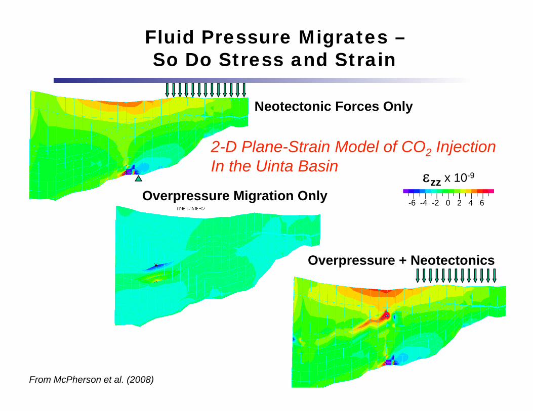
Fluid Pressure Migrates –So Do Stress and Strain
Neotectonic Forces Only
x 10-9
2-D Plane-Strain Model of CO2 InjectionIn the Uinta Basin
zz x 10
-6 -4 -2 0 2 4 6Overpressure Migration Only
Overpressure + Neotectonics
From McPherson et al. (2008)

Neotectonic Forces (Current Stress-State) Must Be Addressed
Neotectonic Forces Only
x 10-9
2-D Plane-Strain Model of CO2 InjectionIn the Uinta Basin
zz x 10
-6 -4 -2 0 2 4 6Overpressure Migration Only
Overpressure + NeotectonicsNote forecasted
compression of caprock
during Becomes mild tensile deformation
From McPherson et al. (2008)
injection tensile deformation with neo-tectonic forces included

Some Specific Types of Fractures/Faults
(1) A discontinuity that dilates (or contracts) normal-to-its-plane only, creating a high (or low) permeability conduitlow) permeability conduit
(2) A discontinuity that dilates due to shear with a moderate normal stress initiallyLe
llan
(200
5)
a moderate normal stress, initially increasing permeability, but then sealing as fault gouge is produced
achu
and
McL
(3) A discontinuity that shears under high compressive stress, forming a low: H
awke
s, B
a
compressive stress, forming a low permeability barrier
Because of the relationship between
From
Because of the relationship between permeability, in-situ stress, and resulting strain is fundamentally critical.

Some Sources of Uncertainty(based on both experimental and modeling results)
1) Initial stress state – vertical, minimum horizontal, maximum horizontal stress orientationmaximum horizontal, stress orientation
2) Elastic / mechanical data - including Young’s modulus Poisson’s ratio Biot’s parameter Le
llan
(200
5)
modulus, Poisson s ratio, Biot s parameter, compressive/tensile rock strength
3) Rock porosity, permeability, density achu
and
McL
) p y p y y
4) Presence of pre-existing fractures / faults
: Haw
kes,
Ba
5) Capillary entry pressure data From

Some Sources of Uncertainty(based on both experimental and modeling results)
6) Multiphase data in general - capillary pressure functions, relative permeability, irreducible saturations, etc.
7) Stress-sensitivity of permeability and porosity
Lella
n(2
005)
8) Hydraulic diffusivity - for forecasting pressure propagation in the reservoir and within the caprock ac
huan
d M
cL
above/below it
9) Lack of quantitative correlation between
: Haw
kes,
Ba
deformation and induced seismicity – e.g., whether seismicity will be induced and its magnitude
10)Di t C ti A h
From
10)Discrete versus Continuum Approaches –general lack of data for both; grid-effects in both; scaling and calibration limitations of both

Outline
• Assessment Objectives
• Geochemical Impacts on Caprock Integrity
• Geomechanical Impacts on Caprock Integrity
• Coupling Geochemical and Geomechanical Processes: Competing Roles
• Assessment Objectives
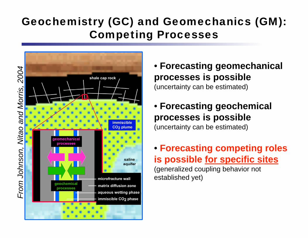
Geochemistry (GC) and Geomechanics (GM): Competing Processes
04
• Forecasting geomechanical i ibl
Mor
ris, 2
00 processes is possible (uncertainty can be estimated)
F ti h i l
ao a
nd M • Forecasting geochemical
processes is possible (uncertainty can be estimated)
nson
, Nita
• Forecasting competing roles is possible for specific sites
From
Joh
n p p(generalized coupling behavior not established yet)
F

Geochemistry (GC) and Geomechanics (GM): Competing Processes
04 Johnson et al. (2005)
Mor
ris, 2
00 concluded that the competing geomechanical deformation and
ao a
nd M deformation and
geochemical changes may counterbalance each
nson
, Nita may counterbalance each
other.
From
Joh
n
However:Time-scales of both must b l d llF be resolved well

Example of Coupled GM and GC: the “Fracture Valve” Conceptual Model
(1) Overburden minimizes extension and fracturing.
(2) Injection pressure reduces (200
8)
effective stress and offsets overburden, causing fracturing.
son
et a
l.
Induced Overpressures
(3) As CO2 is injected, CaCO3-laden fluid migrates into open fractures M
cPhe
rs
fractures.
(4) pCO2 in fractures < pCO2 in HC
From
Induced Overpressures
zone, therefore CaCO3precipitates and seals fractures.
Induced Overpressures

Outline
• Assessment Objectives
• Geochemical Impacts on Caprock Integrity
• Geomechanical Impacts on Caprock Integrity
• Coupling Geochemical and Geomechanical Processes: Competing Roles
• Assessment Objectives

Primary Assessment Objectives
FOR EACH SITE: • geochemical (GC) processes that degrade caprock integrityg g y
• geomechanical (GM) processes that degrade caprock integrityg p g y
• coupling GM and GC
• resolving uncertainties associated with subsurface properties, GM and GC
• resolving competing time-scales of GM and GC
• resolving spatial-scaling limitations (e.g., calibration using lab-scale data)

Interested in additional discussion? Many authors of caprock studies here. Some are:
Sylvain Thibeau -- wettability alteration of caprock minerals and interfacial tensions between CO2 and brineIsabelle Czernichowski-Lauriol --reactive transport in the Sleipner caprockMohamed Azaroual -- reactive transport in the Sleipner caprockJohnny Rutqvist - deformation effects of y qinjection; focused work on caprock/reservoir systems Jens Birkholzer -- deformation effects of injectionStefan Bachu – geomechanics of caprockscaprocksSeveral others -


Data Supporting the Conceptual Model
Conceptual Model Surface ElevationS N
DFZ anticlines:
2000
atio
n (m
)
DFZ1500Elev
a
0 10 20 30
Local flexure anticline
0 10 20 30Distance (km)
• Local flexure = anticline
• DFZ anticline shows intense fracturing
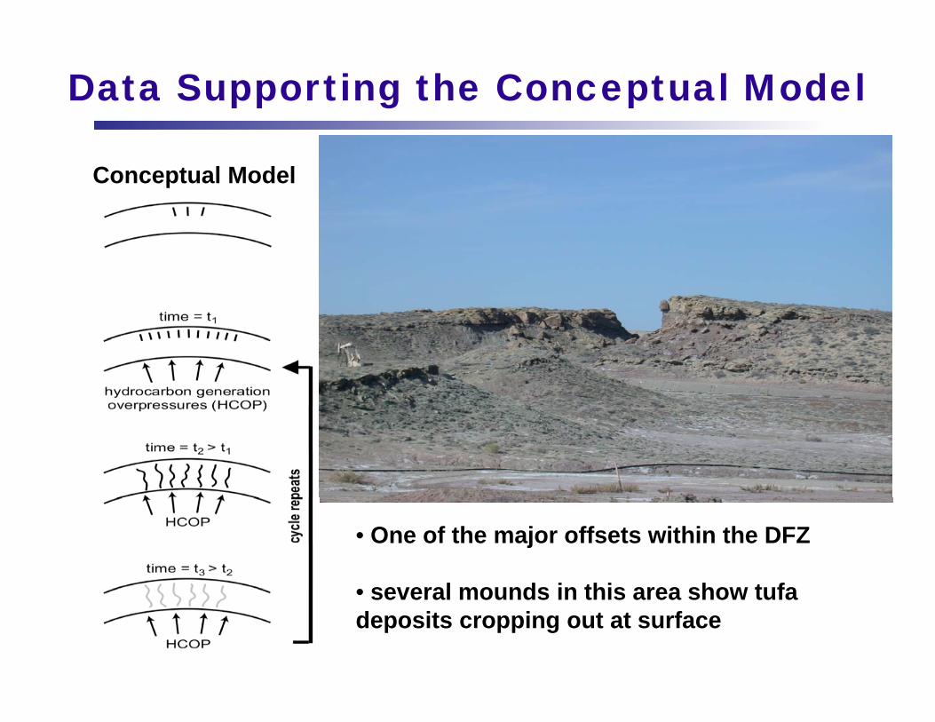
Data Supporting the Conceptual Model
Conceptual Model
• One of the major offsets within the DFZ
• several mounds in this area show tufa• several mounds in this area show tufa deposits cropping out at surface

Data Supporting the Conceptual Model
Conceptual Model
• concretions at surface also• concretions at surface also observed in several areas of the DFZ

Data Supporting the Conceptual Model
Conceptual Model
Scale -----3 m3 m
F i h d• Facies change and tufa deposits at surface

Data Supporting the Conceptual Model
Conceptual Model
• Small calcite veinlets, Duchesne Graben area

Data Supporting the Conceptual Model
Conceptual ModelMultiple Stages of Fluid Flow:(1) east-west trending fractures in Duchesne Graben have calcite filled fractures with gilsonite “injected”gilsonite injected
5 cm

Data Supporting the Conceptual Model
Conceptual Model
Multiple Stages of Fluid Flow:(2) north-south trending(2) north south trending fractures in Duchesne Graben have gilsonite only (no calcite)

Data Supporting the Conceptual Model
Conceptual Model
Also: outcrop examination (left) and thin-sections suggest multiple stages of fluid flow, evidenced by two+ stages of calcite mineralization

106
General Simulation Results: Pressure Propogates Consistent With l t
105
met
ers) No CO2 ahead of pressure plume
3
104
Dis
tanc
e (m
102
103
Mig
ratio
n D
101
10
e P
lum
e M
100
Pre
ssur
e
1 month
6 months1 y 2 y
3 y 4 y5 y
6 y10 y
20 y30 y
50 y100 y
1000 y
106
107
108
109
1010
1011
10-1
Time (seconds)
1 month 6 y
106
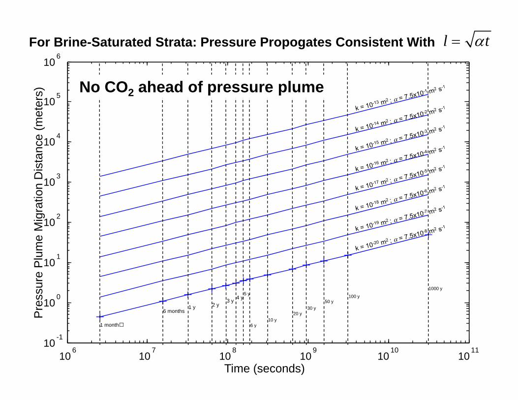
For Brine-Saturated Strata: Pressure Propogates Consistent With l t
105
met
ers) No CO2 ahead of pressure plume
3
104
Dis
tanc
e (m
102
103
Mig
ratio
n D
101
10
e P
lum
e M
100
Pre
ssur
e
1 month
6 months1 y 2 y
3 y 4 y5 y
6 y10 y
20 y30 y
50 y100 y
1000 y
106
107
108
109
1010
1011
10-1
Time (seconds)
1 month 6 y

106
For CO2-Saturated Strata: Pressure Propogates Consistent With l 0.1t
105
met
ers)
3
104
Dis
tanc
e (m
102
103
Mig
ratio
n D
101
10
e P
lum
e M
100
Pre
ssur
e
106
107
108
109
1010
1011
10-1
Time (seconds)

106
Comparison: Pressure Propagation with and without CO2
105
met
ers)
3
104
Dis
tanc
e (m
102
103
Mig
ratio
n D
101
10
e P
lum
e M
100
Pre
ssur
e
1 month
6 months1 y 2 y
3 y 4 y5 y
6 y10 y
20 y30 y
50 y100 y
1000 y
106
107
108
109
1010
1011
10-1
Time (seconds)
1 month 6 y

I l ft lib ti i j ti it i
Useful Analytical EquationsIn general, after calibrating injection site reservoir simulation models with observed pressure trends and with tracer data, we found that the simulation results are ,generally consistent with the following analytical equations for forecasting pressure propagation:
Using Standard Hydraulic Diffusivity:
l tl t Brine-saturated media
l 0 1t CO t t d dil 0.1t CO2-saturated media
Using Hydraulic Diffusivity Based on CO2 Properties:
l 0.001CO2t CO2-saturated media

Aqueous TrappingFirst, CO2 becomes carbonic acid
CO2 (g) + H2O = H2CO3 (slow reaction)
Followed by rapid dissociationy pH2CO3 = H+ + HCO3
- (very fast reaction)