M-125-M-A-E - DTC Tecnología |Soluciones en tecnología ... Manual (M)RBA250-1... · Pinion gear...
56
1) The illustrations used in this Manual are those of the right-handed type (R); the left-handed type (L) has the same structure except that it is mirror imaged. 2) Before using the Rotary Table, we recommend you to read this Manual thoroughly. Keep this Manual in an easily accessible place so that you can read it anytime necessary. RBA-250 Maintenance Manual (M)RBA250-1-08AE April, 2010
Transcript of M-125-M-A-E - DTC Tecnología |Soluciones en tecnología ... Manual (M)RBA250-1... · Pinion gear...

1) The illustrations used in this Manual are those of
the right-handed type (R); the left-handed type
(L) has the same structure except that it is
mirror imaged.
2) Before using the Rotary Table, we recommend
you to read this Manual thoroughly.
Keep this Manual in an easily accessible place so
that you can read it anytime necessary.
RBA-250
Maintenance Manual
(M)RBA250-1-08AE
April, 2010


M-125-M
Contents
♦Foreword . . . . . . . . . . . . . . . . . . . . . . . . . . . . . . . . . . . . . . . . . . . . . . . 1♦General Structure of the Rotary Table. . . . . . . . . . . . . . . . . . . . . . . . . 2♦Auxiliary Work Accompanying Maintenance Work . . . . . . . . . . . . . . . 6♦Mounting and Dismounting the Motor Cover Section . . . . . . . . . . . . . 8♦Mounting and Dismounting the Cable Connector Box. . . . . . . . . . . . . 10♦Connecting and Disconnecting the Piping . . . . . . . . . . . . . . . . . . . . . . 12♦Mounting and Dismounting the Side Cover . . . . . . . . . . . . . . . . . . . . . 13♦Replacing the Proximity Switch of the Clamp Confirmation Unit . . . . . 14♦Replacing the Solenoid Valve . . . . . . . . . . . . . . . . . . . . . . . . . . . . . . . 16♦Replacing the Proximity Switch
of the ZRN Deceleration Signal Unit . . . . . . . . . . . . . . . . . . . . . . . . . . 20♦Adjusting the ZRN Dog Position . . . . . . . . . . . . . . . . . . . . . . . . . . . . . 22♦Maintenance of the Air-hydro Booster . . . . . . . . . . . . . . . . . . . . . . . . . 26♦Measuring Worm Gear Backlash. . . . . . . . . . . . . . . . . . . . . . . . . . . . . 30♦Adjusting Worm Gear Backlash. . . . . . . . . . . . . . . . . . . . . . . . . . . . . . 34♦Parts List . . . . . . . . . . . . . . . . . . . . . . . . . . . . . . . . . . . . . . . . . . . . . . . 38
-A


M-125-M
♦Foreword
Strictly observe the following conditions when carrying out maintenance work of the Rotary Table.
1) When conducting maintenance work of the Rotary Table, refer to three instruction manuals listed below:
Safety Instructions and RecommendationsThis instruction manual describes the safety instructions to be followed when installing, operating, and conducting maintenance work of the Rotary Table.As a supplement, recommendations for the use of the Rotary Table as well as a glossary of terms used in the instruction manuals are included.
Setup ManualThis instruction manual describes the specifications and overview of the Rotary Table, prerequisites for installation on the machine tool, and troubleshooting.
Maintenance ManualThis instruction manual describes maintenance work associated with adjustment or replacement of the major components of the Rotary Table.
∗ The Maintenance Manual is an instruction manual intended for maintenance staff.It is required that maintenance staff must have obtained the required skill and qualification as a maintenance specialist at your company.
∗ Operators of transport equipment associated with maintenance work must be qualified personnel with the appropriate license for such equipment.
2) Before carrying out necessary work, carefully read these instruction manuals as well as the machine tool instruction manual and thoroughly understand all procedures and instructions to be followed.
∗ Be sure to understand the structure of the machine tool and the Rotary Table before commencing the work.
If you have any questions about the description in this Manual, or if you find any serious problem or trouble, contact TSUDAKOMA for detailed information.
1
-A

♦General Structure of the Rotary Table
Structure of the Main Spindle Section of the Rotary Table
The figure above shows the structure of the main spindle section of the Rotary Table.A worm gear and a turntable clamp unit are assembled in the main spindle section.The force transferred from the drive section is conveyed to the turntable through the worm gear.
Main spindle
Turntable
Turntable clamp unit
Bearing
Worm wheel Main body frame
Rotary scale (Option)
2
M-125-M-A

M-125-M
Structure of the Drive Section of the Rotary Table
The figure above shows the structure of the drive section of the Rotary Table.The drive section consists of a motor, gear engagement section, and worm gear section (including a worm spindle and a worm wheel).
Motor
Worm spindleholder
Gear engagement section
Pinion gear
Idle gear
Spur gear
Main body frame
Air-hydro booster(Pneumatic-hydraulic type)
ZRN deceleration signal unit Clamp confirmation unit
Worm wheel
Worm spindle
Motor cover
Waveform shaping unit(Option)
3
-A

Layout Drawing of the Units
The figure above shows the structure of the unit sections built in the Rotary Table.The Rotary Table is equipped with a ZRN deceleration signal unit, clamp confirmation unit and solenoid valve (in the case of pneumatic-hydraulic clamp type).
ZRN decelerationsignal unit
Solenoid valve(Pneumatic-hydraulic
clamp type)
Clamp confirmation unit
Wiring hole
4
M-125-M-A

M-125-M
5
-A

♦Auxiliary Work Accompanying Maintenance Work
For the maintenance work of the Rotary Table, not only safety measures but also an auxiliary work is required before starting and after finishing the work. Follow the procedure below to conduct the auxiliary work to accompany the maintenance work.
[Instructions]1) Closely follow the instructions described in “Safety Instructions and
Recommendations”.
2) Dismount the workpiece and attachments and stop operating the Rotary Table.
3) Turn off the power (primary power) to the control unit of the machine tool.
4) Stop supplying working fluid pressure and release residual pressure from the working fluid piping.
5) Disconnect interface cables between the Rotary Table and the control unit of the machine tool.
6) Disconnect working fluid piping from the Rotary Table, and cover the terminal of each pipe.
∗ Put match marks at the mounting positions of working fluid pipes for reassembly with a felt pen.
∗ When the Rotary Table needs to be operated temporarily for the maintenance work, working fluid could gush out from working fluid piping during the operation. To assure your own safety, cover the end of each pipe or shut off the supply of working fluid pressure.
7) Dismount the Rotary Table from the machine tool and place it on an appropriate table.
∗ Carry out maintenance work of the Rotary Table referring to the machine tool instruction manual and “♦ Fixing the Rotary Table” and “♦ Lifting the Rotary Table” in the Setup Manual.
8) Conduct the desired maintenance work.
∗ When conducting maintenance work of the Rotary Table, refer to “Safety Instructions and Recommendations”, “Setup Manual”, as well as “Maintenance Manual”.
9) Clean the Rotary Table and the machine tool.
10) Mount the Rotary Table on the machine tool.
∗ Install the Rotary Table on the machine tool referring to the machine tool instruction manual and “♦ Fixing the Rotary Table” and “♦ Lifting the Rotary Table” in the Setup Manual.
6
M-125-M-A

M-125-M
11) Connect the working fluid piping to the Rotary Table.
12) Connect interface cables between the Rotary Table and the control unit of the machine tool.
13) Carry out trial run of the Rotary Table referring to “♦ Trial Run” in the Setup Manual.
14) Mount the workpiece fixing unit and the disconnected attachments on the Rotary Table again.
15) Check that every attachment operates following the instructions described in the machine tool instruction manual.
According to the instructions, the Rotary Table needs to be dismounted from the machine tool before commencing maintenance work. However, if it is difficult to dismount the Rotary Table from the machine tool or if the maintenance work can only be performed properly with the Rotary Table mounted on the machine tool, conduct maintenance work of the Rotary Table without dismounting it from the machine tool.Ensure the safe working environment in the same way as the case where the Rotary Table is dismounted.
1) Never conduct maintenance work unless the safe working environment is ensured.
∗ Any work under unsafe working environment may pose a danger to operators.
1) When operating the Rotary Table during maintenance work, take necessary steps to prevent working fluid from gushing out from each pipeline or working fluid piping in the designated frame of the Rotary Table.
∗ When the power to the control unit is turned on without taking the preventive steps, working fluid will gush out from each pipeline or working fluid piping. This might cause an accident to the operator, resulting in death or severe injury. If working fluid gushes out, the gushing may cause parts or tools to fly off, resulting in damage to the Rotary Table or the machine tool.
2) Connect and disconnect working fluid piping and interface cables according to the instructions in the machine tool instruction manual.
∗ Improper connection of any working fluid piping or interface cable not only could cause a malfunction of the Rotary Table but also pose a danger to workers and operators.
7
-A
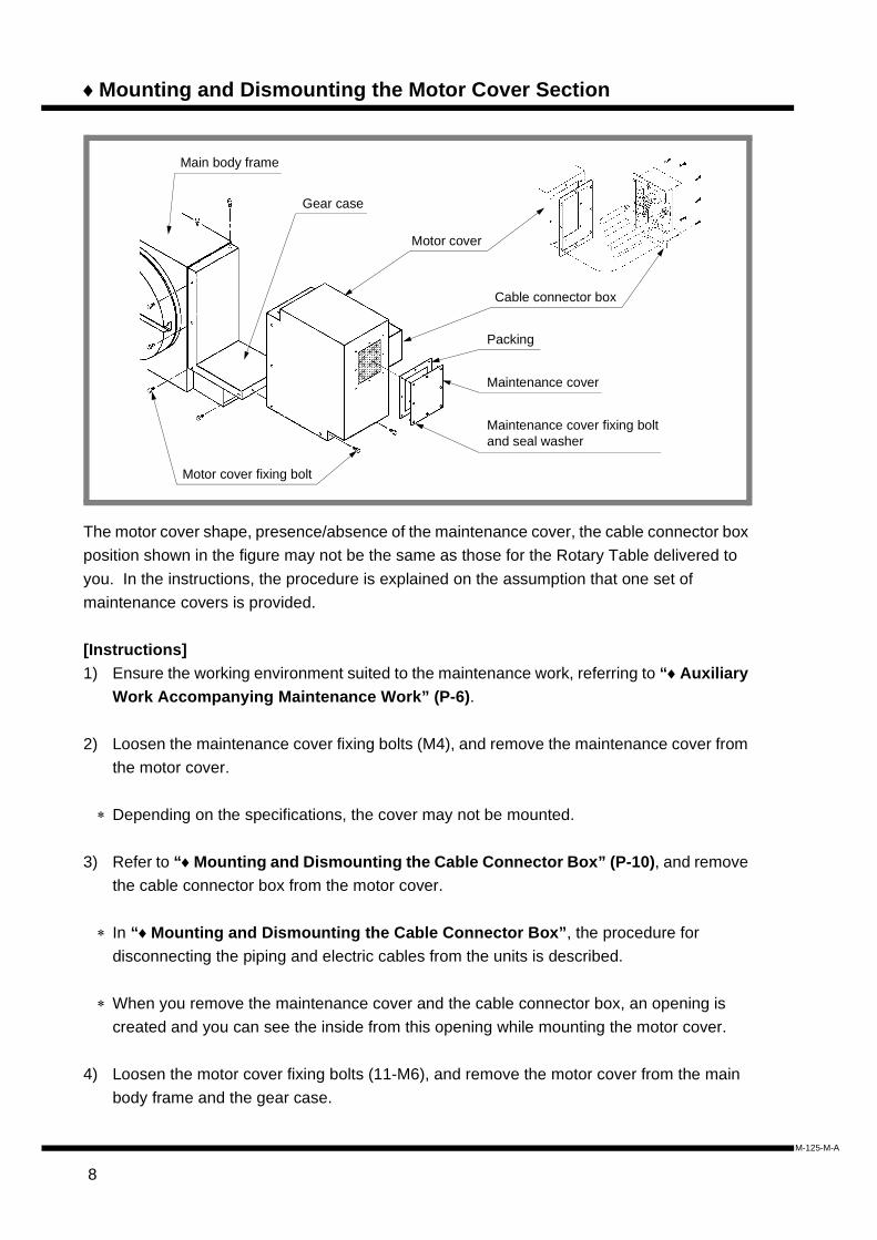
♦Mounting and Dismounting the Motor Cover Section
The motor cover shape, presence/absence of the maintenance cover, the cable connector box position shown in the figure may not be the same as those for the Rotary Table delivered to you. In the instructions, the procedure is explained on the assumption that one set of maintenance covers is provided.
[Instructions]1) Ensure the working environment suited to the maintenance work, referring to “♦Auxiliary
Work Accompanying Maintenance Work” (P-6).
2) Loosen the maintenance cover fixing bolts (M4), and remove the maintenance cover from the motor cover.
∗ Depending on the specifications, the cover may not be mounted.
3) Refer to “♦Mounting and Dismounting the Cable Connector Box” (P-10), and remove the cable connector box from the motor cover.
∗ In “♦Mounting and Dismounting the Cable Connector Box”, the procedure for disconnecting the piping and electric cables from the units is described.
∗ When you remove the maintenance cover and the cable connector box, an opening is created and you can see the inside from this opening while mounting the motor cover.
4) Loosen the motor cover fixing bolts (11-M6), and remove the motor cover from the main body frame and the gear case.
Main body frame
Motor cover
Cable connector box
Packing
Maintenance cover
Maintenance cover fixing bolt and seal washer
Motor cover fixing bolt
Gear case
8
M-125-M-A

M-125-M
∗ The number of motor cover fixing bolts varies depending on the specifications. (11-M6) shows the number and size of the bolts provided on the Rotary Table of the standard specification.
5) Conduct the desired maintenance work.
6) Clean inside the motor cover and the motor cover mounting section.
7) Apply liquid gasket, and attach the motor cover to the main body frame and the gear case.
∗ When attaching, check the inside of the motor cover through the opening where the cable connector box or the maintenance cover is removed to prevent distortion or bending of electric cables and piping as well as damage to the units.
8) Refer to “♦Mounting and Dismounting the Cable Connector Box” (P-10), and attach the cable connector box to the motor cover.
∗ In “♦Mounting and Dismounting the Cable Connector Box”, the procedure for connecting the piping and electric cables to the units is described.
9) Attach the packing and the maintenance cover to the motor cover.Set the seal washer when tightening the maintenance cover fixing bolts (M4).
1) Before applying liquid gasket, remove old liquid gasket from the mating surface.∗ If old liquid gasket remains, coolant or cutting chips may enter inside.
1) When the motor cover is removed, clean the motor cover and the main body frame.
∗ Coolant may gather inside the motor cover and may cause corrosion of the motor cover or main body frame, or a malfunction of the motor. When the cover is removed, be sure to clean the inside. If corrosion occurs, remove corrosion and apply rust-preventive oil to the section.
9
-A

♦Mounting and Dismounting the Cable Connector Box
The cable connector box is equipped with a connector where the electric cables of the motors and units of the Rotary Table are connected and with a pneumatic feed port where the blowout opening for air purging is connected.The figure above is shown for reference only. The shape of the cable connector box, the mounting positions of connectors, as well as the mounting position of the terminal block are not the same as those on the machine delivered to you. For details, check the cable connector box and the electric connection diagram of your machine.
[Instructions]1) Ensure the working environment suited to the maintenance work, referring to “♦Auxiliary
Work Accompanying Maintenance Work” (P-6).
2) Loosen the cable connector box fixing bolts (8-M4), and remove the cable connector box from the motor cover.
3) Remove the electric cables for the units from the terminal block.
4) Refer to “♦Connecting and Disconnecting the Piping” (P-12), and remove the pipe from the piping joint at the backside of the pneumatic feed port.
∗ There are cases where only a blowout port for air purging is provided; in this case, no removal is required. Take a step according to the situation.
Motor cover
Cable connector box
Connector(For the interface cable)
Cable connector box
Cable connector box fixing bolt and seal washer
Electric cables for motors
Packing
Terminal blockElectric cables for units(Connected to the terminal block)
Motor cover
Flexible hose piping
Piping joint
Pneumatic feed port
10
M-125-M-A

M-125-M
5) Disconnect electric cables (for power and detector) from the motor.
∗ Utilize the opening that is created by removing the cable connector box or maintenance cover from the motor cover when disconnecting the cables for the motor.
6) Move the cable connector box to such a position that you can carry out the intended work unhindered.
7) Conduct the desired maintenance work.
8) Clean the cable connector box and the motor cover.
9) Connect electric cables (for power and detectors) to the motor.
10) Refer to the electric connection diagram, and connect electric cables for the units to the terminal block.
11) Refer to “♦Connecting and Disconnecting the Piping” (P-12), and connect the piping to the piping joints.
12) Attach the packing and the cable connector box to the motor cover.
1) Refer to the electric connection diagram when disconnecting or connecting electric cables.
11
-A

♦Connecting and Disconnecting the Piping
Flexible Hose Piping
[Instructions]1) To remove the connecting pipe, push the push ring in the axial direction with your finger
while pulling the pipe.
2) To attach the connecting pipe, insert the pipe into the mounting hole on the piping joint until it reaches the tube end.
3) Pull the pipe lightly and check that it does not come off.
1) Do not remove the connecting pipe with pneumatic pressure being supplied.
2) Do not pull the connecting pipe without pushing the push ring at the piping joint.
1) If you continue other maintenance work with the connecting pipe removed, cover the pipe end with tape or cloth to prevent entry of dust and dirt or damage to the piping joint and the pipe.
∗ If anything is entered in the connecting pipe, it will be conveyed with working fluid to a unit, which may defeat correct operation of the unit or may lead to an accident.
1) If the inserting portion of the connecting pipe is damaged, cut the portion at right angles to the longitudinal direction.
∗ The connecting pipe has a sufficient length and can be cut if necessary. However, if the connecting pipe has been cut several times and is not long enough, replace the pipe with a new one.
How to disconnect How to connect
Push ringPush ring Tube endPiping joint body
12
M-125-M-A

M-125-M
♦Mounting and Dismounting the Side Cover
[Instructions]1) Ensure the working environment suited to the maintenance work, referring to “♦Auxiliary
Work Accompanying Maintenance Work” (P-6).
2) Loosen the side cover fixing bolts (6-M6), and remove the side cover from the main body frame.
3) Conduct the desired maintenance work.
4) Apply liquid gasket, and attach the side cover to the main body frame.
1) Before applying liquid gasket, remove old liquid gasket from the mating surface.∗ If old liquid gasket remains, coolant or cutting chips may enter inside.
Side cover fixing bolt
Main body frame
Side cover
ZRN deceleration signal unit
Clamp confirmation unit
Solenoid valve(Pneumatic-hydraulic clamp type)
13
-A
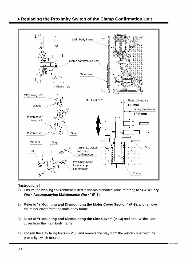
♦Replacing the Proximity Switch of the Clamp Confirmation Unit
[Instructions]1) Ensure the working environment suited to the maintenance work, referring to “♦Auxiliary
Work Accompanying Maintenance Work” (P-6).
2) Refer to “♦Mounting and Dismounting the Motor Cover Section” (P-8), and remove the motor cover from the main body frame.
3) Refer to “♦Mounting and Dismounting the Side Cover” (P-13) and remove the side cover from the main body frame.
4) Loosen the stay fixing bolts (2-M5), and remove the stay from the piston cover with the proximity switch mounted.
Dog
Piston
Fitting dimension
13.5 mm
Piston cover
Piston coverfixing bolt
Washer
Stay fixing bolt
Stay
Nut
Washer Stay
Proximity switch for unclamp confirmation
Proximity switch for clamp confirmation
Fitting clearance
1.0 mmStroke 9 mm
Clamp confirmation unit
Side cover
Main body frame
Piping hole
14
M-125-M-A
M-125-M
5) Loosen the nut (M8) at the proximity switch, and remove the stay from the proximity switch.
6) Adjust a new proximity switch to the fitting dimension of 13.5 mm and secure it to the stay.Tighten the nut (M8) with a torque of 5 N•m.
7) Attach the stay to the piston cover.Tighten the stay fixing bolt (2-M5) with a torque of 7.8 to 9.3 N•m.
∗ Adjust the distance between the proximity switch and the dog to 1.0 mm and secure the switch in this position.The stay fixing bolt mounting section is U-slotted so the position can be adjusted several millimeters.
8) Pass the electric cable for the proximity switch through the cable hole at the main body frame to the motor cover mounting section.
9) Refer to “♦Mounting and Dismounting the Cable Connector Box” (P-10), and connect electric cable for the clamp confirmation unit (proximity switch) to the terminal block.
10) Refer to “♦Mounting and Dismounting the Side Cover” (P-13) and attach the side cover to the main body frame.
11) Refer to “♦Mounting and Dismounting the Motor Cover Section” (P-8) and attach the motor cover to the main body frame.
1) Refer to the electric connection diagram when disconnecting or connecting electric cables.
1) Secure the proximity switches for clamp confirmation and unclamp confirmation to the stay with the specified fitting dimensions.
∗ If the fitting dimension of the proximity switch for clamp/unclamp confirmation is not correct, the switch may collide with the dog or may not detect the dog correctly.
15
-A

♦Replacing the Solenoid Valve
[Instructions]1) Ensure the working environment suited to the maintenance work, referring to “♦Auxiliary
Work Accompanying Maintenance Work” (P-6).
2) Refer to “♦Mounting and Dismounting the Side Cover” (P-13) and remove the side cover from the main body frame.
3) Refer to “♦Connecting and Disconnecting the Piping” (P-12), and remove the pipes from the piping joints at the solenoid valve.
Piping joint
DIN connector fixing bolt
DIN connector
Packing
Solenoid valve body
Manual switch
Manual ON position
Manual OFF position
CapWasher
Seal
DIN connector cover Flat-head screwdriver
Electric cable
DIN connector cover
Lead wire
Terminal blockLead wire fixing screw
(at 2 positions)
Side cover
Bracket
Main body frame
Solenoid valve
Cable
Solenoid valve fixing bolt
Connectingpipe
16
M-125-M-A

M-125-M
∗ It is recommended to put match marks on the connecting pipes and piping joints before removing the piping to assure correct piping during re-connection.
4) Loosen the solenoid valve fixing bolts (2-M3), and remove the solenoid valve from the bracket.
5) Loosen the DIN connector fixing bolt (M3), and remove the DIN connector from the solenoid valve body.
6) Put a match mark across the DIN connector cover and the notch A on the terminal block to show the positional relationship in assembly with a felt pen.
7) Loosen the DIN connector cap, insert a screwdriver in the section A, and pull the terminal block out from the terminal block.
8) Loosen the lead wire fixing screws (2 positions) on the side of the terminal block, and remove the lead wires.
9) Attach a new DIN connector to the electric cable.
∗ Attach the cap, washer, seal and the DIN connector cover to the electric cable in this order, and then connect the lead wires to the terminal block referring to the electric connection diagram.
10) Align the match marks, mount the terminal block on the DIN connector cover, and secure the electric cable with the cap.
11) Attach the DIN connector and the packing to a new solenoid valve.Tighten the DIN connector fixing bolt (M3) with a torque of 30 to 40 N•cm.
12) Attach the solenoid valve to the bracket.
∗ Ensure that the manual switch of the solenoid valve is set to the “OFF” position (• marked position).
13) Refer to “♦Connecting and Disconnecting the Piping” (P-12), and connect the piping to the piping joints at the solenoid valve.
∗ Refer to “♦Piping System Diagram” in the Setup Manual, align the match marks and connect the pipes to the piping joints.
14) Refer to “♦Mounting and Dismounting the Side Cover” (P-13) and attach the side cover to the main body frame.
17
-A

15) Check operations of the solenoid valve.
1) Refer to the electric connection diagram when disconnecting or connecting electric cables.
2) When connecting the piping, refer to “♦ Piping System Diagram” in the Setup Manual.
∗ If the piping is wrongly connected, clamping operation cannot be performed. Be sure to check the piping system diagram before the connection.
∗ It is recommended to put match marks on the connecting pipes and piping joints before removing the piping to assure correct piping during re-connection.
1) Before removing the DIN connector of the solenoid valve or the terminal block, check and record the positional relation, such as the mounting direction.
∗ To keep the new solenoid valve in the same direction as before, record the mounting direction before removing the old one. Attach the new one while referring to the record.
∗ Before removing lead wires, record the connecting position of each lead wire at the terminal block.
2) Keep the manual switch of the solenoid valve in the “OFF” position (• marked position).
1) If there is no damage on the existing DIN connector section, it can be used continuously.
∗ If the existing DIN connector section (DIN connector cover, terminal block, packing) can still be used, replace the solenoid valve only and use the existing DIN connector section again, and keep the new DIN connector section as a spare part.
18
M-125-M-A

M-125-M
19
-A

♦Replacing the Proximity Switch of the ZRN Deceleration Signal Unit
[Instructions]1) Ensure the working environment suited to the maintenance work, referring to “♦Auxiliary
Work Accompanying Maintenance Work” (P-6).
2) Refer to “♦ Supplying and Replacing Lubricant” in the Setup Manual, and drain lubricant from the main body frame of the Rotary Table.
3) Refer to “♦Mounting and Dismounting the Motor Cover Section” (P-8), and remove the motor cover from the main body frame.
4) Refer to “♦Mounting and Dismounting the Side Cover” (P-13) and remove the side cover from the main body frame.
5) Loosen the holder fixing bolt (M6), and remove the ZRN deceleration signal unit from the main body frame.
Side cover fixing bolt
ZRN dog
Main body frame
O-ring (P16)
Holder
M6-tapped hole
Nut
Seal washer
HolderFixing bolt
Holder
Fitti
ng d
imen
sion
28.3
± 0
.2 m
m
Proximity switch
O-ring (P16)
Side cover
Piping hole
ZRN deceleration signal unit(Proximity switch)
20
M-125-M-A

M-125-M
∗ The holder is equipped with two M6-tapped holes. Remove the holder fixing bolts, insert the M6 bolts of longer lengths into the tapped hole to pull the holder out.
6) Loosen the nut (M12) and remove the proximity switch from the holder.
7) Adjust the new proximity switch to the fitting dimension of 28.3 ± 0.2 mm and secure it to the holder.Tighten the nut with a torque of 10 N•m.
8) Attach the holder (ZRN deceleration signal unit) to the main body frame.Tighten the holder fixing bolt (M6) with a torque of 13.2 to 15.7 N•m.
9) Wipe away lubricant from the neighboring surfaces if any lubricant flows out.
10) Pass the electric cable for the proximity switch through the cable hole at the main body frame to the motor cover mounting section.
11) Refer to “♦Mounting and Dismounting the Cable Connector Box” (P-10), and connect electric cable for the ZRN deceleration signal unit (proximity switch) to the terminal block.
12) Refer to “♦Mounting and Dismounting the Side Cover” (P-13) and attach the side cover to the main body frame.
13) Refer to “♦Mounting and Dismounting the Motor Cover Section” (P-8) and attach the motor cover to the main body frame.
14) Refer to “♦ Supplying and Replacing Lubricant” in the Setup Manual, and supply lubricant to the main body frame of the Rotary Table.
15) Set the zero point position again.
∗ For zero return operation or confirmation and adjustment of the zero point position, refer to
the machine tool instruction manual and follow the instructions.
1) Refer to the electric connection diagram when disconnecting or connecting electric cables.
21
-A

♦Adjusting the ZRN Dog Position
[Instructions]1) Ensure the working environment suited to the maintenance work, referring to “♦Auxiliary
Work Accompanying Maintenance Work” (P-6).
2) Refer to “♦ Supplying and Replacing Lubricant” in the Setup Manual, and drain lubricant from the main body frame of the Rotary Table.
3) Refer to “♦Mounting and Dismounting the Side Cover” (P-13) and remove the side cover from the main body frame.
4) Perform zero return operation.
∗ When zero return operation is performed, the ZRN dog comes near the center of the ZRN dog position adjustment hole.
5) Refer to “♦ Zero Return and Grid Shift Offset Amount” in the Setup Manual, and check the positional relationship between the ZRN deceleration signal unit and the ZRN dog after the zero return operation.
6) Remove the plug (R3/8) from the ZRN dog position adjustment hole.
ZRN dog fixing bolt
Allen wrench
Hole for adjusting theZRN dog position
ZRN deceleration signal unit(Proximity switch)
Side cover fixing bolt
ZRN dog
Side cover
Main body frame
Plug(upper)
Plug (R3/8) Plug(lower)
22
M-125-M-A

M-125-M
7) Use manual control devices and adjust the ZRN dog fixing bolt near the center of the adjustment hole.
8) Insert the Allen wrench into the hole for adjusting the dog position, and loosen the ZRN dog fixing bolt (M5) by making a half to one turn.
∗ When the ZRN dog fixing bolt is loosened, do not remove the Allen wrench from the ZRN dog fixing bolt. Removing the Allen wrench could cause the ZRN dog to slip, which disables adjustment.
9) Move the ZRN dog using the Allen wrench as required, and tighten the ZRN dog fixing bolt (M5) to secure the ZRN dog.
10) Apply sealant and attach the plug (R3/8) to the ZRN dog position adjustment hole.
11) Clean up lubricant that flows out around.
12) Refer to “♦Mounting and Dismounting the Side Cover” (P-13) and attach the side cover to the main body frame.
13) Refer to “♦ Supplying and Replacing Lubricant” in the Setup Manual, and supply lubricant to the main body frame.
14) Perform zero return operation and confirm the zero point position.
∗ For zero return operation or confirmation and adjustment of the grid shift amount, refer to the operation manual of the control unit and follow the instructions.
Rotation direction at zero return
Right-handed type Left-handed type
CW rotation Upper plug Lower plug
CCW rotation Lower plug Upper plug
23
-A

1) Turn on the power only when operating the Rotary Table, and use manual control devices for operation. When operation has been completed, turn the power (primary power) off.
1) When loosening the ZRN dog fixing bolt, do not loosen it by more than one revolution.
∗ If you loose it by more than one revolution, the ZRN dog may come off from the main spindle.
24
M-125-M-A

M-125-M
25
-A

♦Maintenance of the Air-hydro Booster
[Instructions]1) Ensure the working environment suited to the maintenance work, referring to “♦Auxiliary
Work Accompanying Maintenance Work” (P-6).
2) Refer to “♦ Supplying Hydraulic Oil to the Air-hydro Booster” in the Setup Manual, and drain hydraulic oil from the air-hydro booster.
∗ After hydraulic oil is drained, keep the cap and plug removed from the feed port and drain port.
Cover fixing bolt
Main body frame
Cover
Cylinder
Cylinder cover fixing bolt
Bolt
Cylinder section
Main body frame
O-ring (S42)
O-ring (G50)
Piston
Snap ring
Cylinder cover
Cylinder
HSD packing (HSD-45)
SWA wear ring (SWA-45)
O-ring (G30)
SKY packing (SKY-16)
PENTA seal (PS-16)
M6-tapped hole
Cover
26
M-125-M-A

M-125-M
3) Loosen the cover fixing bolts (4-M6), and remove the cylinder section from the main body frame.
∗ The end face of the cover has two M6-tapped holes. Insert the bolts into the tapped holes, and pull the bolts slowly to detach the cylinder section from the main body frame.
4) Wipe hydraulic oil off the cylinder mounting section of the main body frame.
∗ If hydraulic oil is not wipe off, it may permeate into the solenoid valve when you insert the cylinder. Permeated hydraulic oil will damage the solenoid valve or contaminate the unit housings. Be sure to remove hydraulic oil completely.
5) Loosen the cylinder cover fixing bolts (2-M5), and remove the cover from the cylinder section.
6) Remove the snap ring from the cylinder, and remove the cylinder cover from the cylinder.
∗ The end face of the cylinder cover has two M5-tapped holes. Insert the bolts into the tapped holes, and pull the bolts slowly to detach the cylinder cover from the cylinder.
7) Remove the piston from the cylinder.
8) Clean the removed O-rings, seals or parts, and if any part is damaged, replace it with a new one.
9) Assemble the O-rings (G42, G50, G30) and seals (HSD-45, SWA-45, PS-16, SKY-16) to the parts (cylinder cover, cylinder, piston) in the same conditions as those before disassembly.
Plug
Hydraulic oil feed portHydraulic oil drain port
Hydraulic oil drain portHydraulic oil feed portOil gauge
27
-A

∗ Before attaching, apply grease or lubricant to the O-rings and seals.
∗ When attaching the PENTA seal or SKY packing to the designated groove, refer to the reference figure and check the orientation of the seal or packing.
10) Insert the piston into the cylinder.
11) Insert the cylinder cover into the cylinder, and secure it with the snap ring.
12) Attach the cover to the cylinder.Tighten the cylinder cover fixing bolts (2-M5) with a torque of 9.3 N•m.
13) Insert the cylinder into the cylinder mounting section at the main body frame.
∗ As you insert the cylinder, hydraulic oil may flow out from the hydraulic oil drain port at the main body frame. Do not block the hydraulic oil drain port with a plug. This works for bleeding air when inserting the cylinder.
14) Attach the cover to the main body frame.Tighten the cover fixing bolts (4-M6) with a torque of 15.7 N•m.
15) Refer to “♦ Supplying Hydraulic Oil to the Air-hydro Booster” in the Setup Manual, stop up the hydraulic oil drain port with the plug, and supply hydraulic oil to the air-hydro booster.
16) Refer to “♦ Bleeding the Turntable Clamp Unit” in the Setup Manual, and bleed air from the clamp unit.
SKY packing (SKY-16)
PENTA seal(PS-16)
Piston
28
M-125-M-A

M-125-M
1) Assemble the parts being careful not to damage the sliding sections at the piston or cylinder.
∗ If any sliding section at the piston or cylinder, the air-hydro booster cannot work well resulting in lowering the clamping force for the turntable.
2) Attach the PENTA seals and the SKY packing to the designated grooves correctly in the specified direction.
∗ If the orientation is not correct, working fluid may leak resulting in a malfunction of the air-hydro booster.
1) When the cylinder section has been removed, wipe hydraulic oil off the cylinder mounting section of the main body frame.
∗ If hydraulic oil is not wipe off, it may permeate into the solenoid valve when you insert the cylinder. Permeated hydraulic oil will damage the solenoid valve or contaminate the unit housings. Be sure to remove hydraulic oil completely.
2) During the work, keep the cap and plug removed from the feed port and drain port of the air-hydro booster.
∗ These ports work for bleeding air when removing or inserting the cylinder section.
29
-A

♦Measuring Worm Gear Backlash
[Instructions]1) Ensure the working environment suited to the maintenance work, referring to “♦Auxiliary
Work Accompanying Maintenance Work” (P-6).
2) Place the Rotary Table on an appropriate table for measurement. Wait until the temperature of the Rotary Table reaches 20°C by setting the measuring room air conditioner to 20°C.
3) Prepare a block gauge and a dial gauge that reads up to 0.002 mm.
4) Connect interface cables of the Rotary Table and the control unit.
5) Set a dial gauge to the side of the T-slot near the outer surface of the turntable.
∗ The dial gauge should be set in such a position that the displacement in the working direction shown in the reference figure can be measured.
6) Apply a working torque in one direction shown by the arrows. Then, release the working torque, and read the indication on the dial gauge. Apply a working torque in the other direction. Release the working torque, and read the indication on the dial gauge.
∗ The working torque is about 18 to 25 N•m.However, this working torque value is given only for reference. Apply enough torques to make the worm and the worm wheel teeth contact precisely.
∗ In the reference figure, a slab is attached to the T-slot, and the working torque is manually applied using the slab.
Rotating axis center
Measuring radiusposition
Dial gaugeDial gauge
Turntable
Working direction
30
M-125-M-A

M-125-M
7) Record the difference between two dial gauge readings that are measured by moving the axis in both directions.This difference in dial gauge reading should be taken as the backlash.
8) Remove the dial gauge and the slab.
9) Rotate the turntable about 45 degrees using manual control devices to change the worm gear engaging position.
10) Repeat steps 7) through 9) to measure the backlash, and record the measuring position and the backlash.
∗ Measure the backlash at eight positions (in increments of 45 degrees).
11) From the recorded backlash, judge whether the backlash adjustment is necessary or not.
∗ If the measured backlash amount exceeds the limit of the compensable range by the control unit, backlash adjustment is required.
Relation between the measured value and the converted backlash amount
∗ When adjusting the backlash, adjust the engaging position of the worm gear so that the backlash will be minimal.
Converted value of minimum backlash amount at the measuring radius position
Measuring radius position
Approx. 9 µm (1 sec. ≈ 0.606 µm)125 mm
(φ250 mm)Note: The converted value refers to the measurement at the measuring radius position
when the minimum backlash amount is 15 sec.
31
-A

1) Turn on the power only when operating the Rotary Table, and use manual control devices for operation. When operation has been completed, turn the power (primary power) off.
∗ Remove the dial gauge and the slab before operating the Rotary Table.
1) The temperature may affect backlash measurement. Do not conduct measurement before the temperature of the Rotary Table reaches around 20°C.
2) Make backlash measurement when the tooth flanks of the worm teeth and the worm wheel teeth are in good contact.
∗ The following figure illustrates the clearance at tooth flanks (backlash amount) at the engaging area between the worm teeth and worm wheel teeth.
Since the movement distance (clearance) is measured when the worm wheel is moved from the status (A) to the status (B) as the backlash amount, the tooth flanks of the worm teeth and the worm wheel teeth must be in good contact. Apply a working torque until the worm teeth and the worm wheel teeth come into contact.
Status (B)Status (A)
Worm wheel
Worm spindle (fixed)
Clearance (Backlash amount)
32
M-125-M-A

M-125-M
33
-A
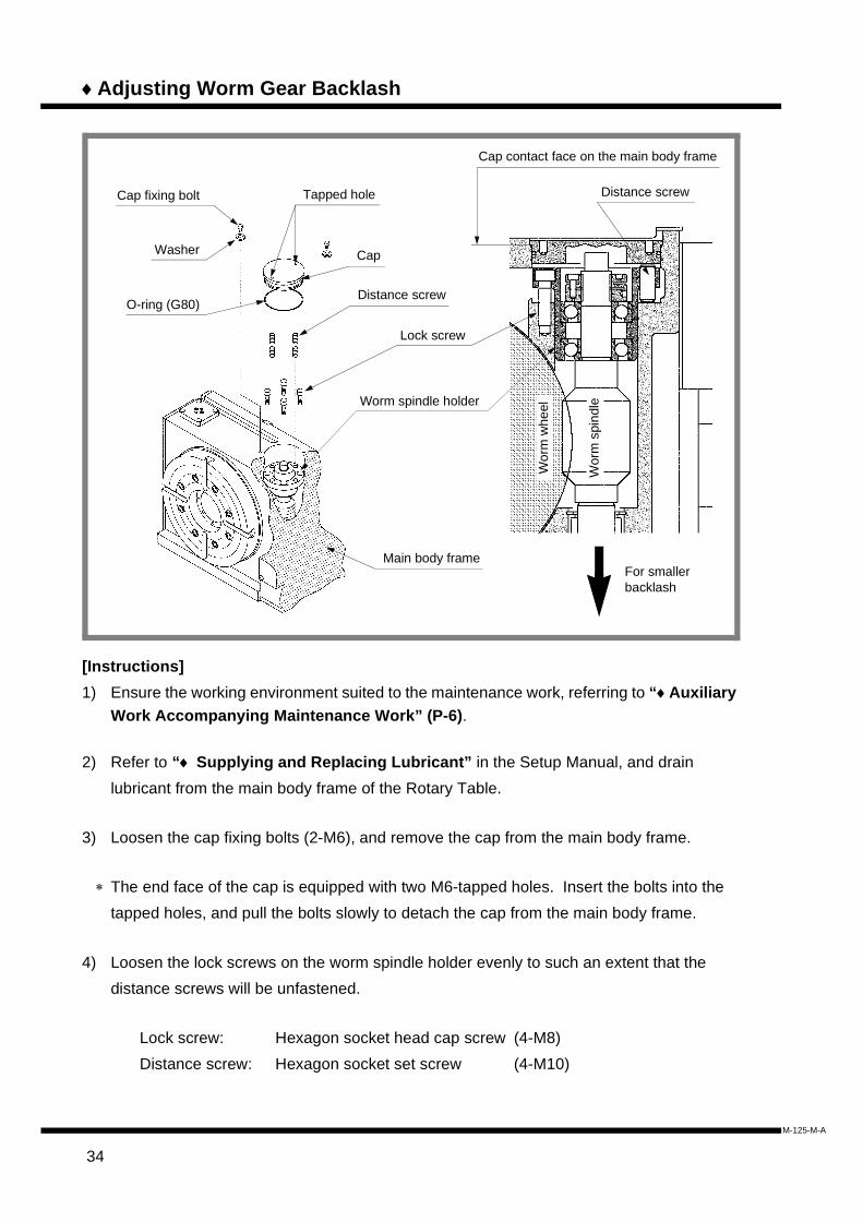
♦Adjusting Worm Gear Backlash
[Instructions]1) Ensure the working environment suited to the maintenance work, referring to “♦Auxiliary
Work Accompanying Maintenance Work” (P-6).
2) Refer to “♦ Supplying and Replacing Lubricant” in the Setup Manual, and drain lubricant from the main body frame of the Rotary Table.
3) Loosen the cap fixing bolts (2-M6), and remove the cap from the main body frame.
∗ The end face of the cap is equipped with two M6-tapped holes. Insert the bolts into the tapped holes, and pull the bolts slowly to detach the cap from the main body frame.
4) Loosen the lock screws on the worm spindle holder evenly to such an extent that the distance screws will be unfastened.
Lock screw: Hexagon socket head cap screw (4-M8)Distance screw: Hexagon socket set screw (4-M10)
Cap fixing bolt
For smaller backlash
Main body frame
Tapped hole
CapWasher
O-ring (G80)
Lock screw
Worm spindle holder
Wor
m w
heel
Wor
m s
pind
le
Distance screw
Distance screw
Cap contact face on the main body frame
34
M-125-M-A

M-125-M
5) Loosen the distance screw evenly by the number of turns calculated from the required amount of adjustment using the following formula.
N = (C − B)/A .......................... Required amount of adjustment
If N > 0, loosen the distance screws.If N < 0, tighten the distance screws.A: Converted amount of adjustment per rotation of the distance screw at the
measuring position (µm)B: Converted amount at the measuring position for the setting backlash
amount (µm)C: Minimum backlash amount obtained by backlash measurement (µm)
6) Tighten the lock screws evenly and slightly, measure the fixed position of the worm spindle holder, and check that it is below the limit.
∗ If the worm spindle holder fixed position reaches the limit, the life of the worm gear on the Rotary Table should be considered as expired and no further adjustment is possible. In this case, stop conducting the backlash adjustment and stop using the Rotary Table as well.
Converted amount of adjustment per rotation of the distance screw Measuring
radius positionConverted amount of adjustment in seconds
A
Approx. 87.5 sec. Approx. 53 µm125 mm
(φ250 mm)
Converted amount for the setting backlash amount: B Measuring radius position20 sec. 25 sec. 30 sec. 35 sec.
12 µm 15 µm 18 µm 21 µm125 mm
(φ250 mm)
Distance limit
23 mmWorm spindle holder
Fixed position afteradjustment
Cap contact faceon the main body frame Distance limit
35
-A

7) Check that there is no clearance between the end face of the distance screw and the main body frame. If any clearance is observed, try to remove it.
∗ The sketch below is an illustration of a developed view to show the relation of distance screws with lock screws, the worm spindle holder and the main body frame.If there is any clearance between the end face of a distance screw and the main body frame as shown in the sketch, the worm spindle holder may be inclined when fastening the lock screws with the designated torque.
8) Tighten the lock screws (4-M8) evenly with a torque of 31.4 N•m and fix the worm spindle holder.
9) Measure the worm spindle holder fixed position again, and compare the fixed position and the limit position to determine whether it is usable or not.
10) Measure the backlash again, referring to “♦Measuring Worm Gear Backlash” (P-30).
11) When the measured value is not the setting backlash amount, repeat the adjustment from step 4).
∗ The optimum backlash cannot be obtained with only one adjustment. Carefully repeat the adjustment several times.
12) Record the adjustment amount of the worm spindle holder.
13) Set the O-ring (G80), attach the cap to the main body frame, and secure them with the cap fixing bolts.
14) Refer to “♦ Supplying and Replacing Lubricant” in the Setup Manual, and supply lubricant to the main body frame of the Rotary Table.
Flange section of worm spindle holder
Main body frame
Lock screw Distance screw Clearance
36
M-125-M-A

M-125-M
1) When adjusting and tightening distance screws and lock screws, be sure to use the specified torque and distribute the pressure evenly.
1) NEVER remove any lock screws. Loosen them only to unfasten the distance screws.
2) Stop conducting backlash adjustment as well as using the Rotary Table when the worm spindle holder fixed position reaches the limit.
∗ If the worm spindle holder fixed position reaches the limit due to backlash adjustment, the life of the worm gear on the Rotary Table should be considered as expired.
∗ Before adjusting the backlash, be sure to measure and record the worm spindle holder fixed position. Based on the date and the position data of backlash adjustment, the increasing ratio of backlash can be obtained and the next adjustment timing can be estimated.
3) Be sure to adjust the backlash to an optimum value.∗ Excessively large backlash could produce play at worm gears, thus causing vibration
or chattering due to cutting resistance during continuous cutting.∗ Excessively small backlash could cause abrasion and seizure of the gear.
4) After the adjustment, be sure to confirm the zero return operation and set the zero point position.
∗ The relative engaging position of the worm gears may shift after adjustment, when the zero point position may also shift very slightly. Set the zero point position again.
37
-A

♦Parts List
Maker AddressPlease purchase each part from the manufacturer specified in the “Maker” column of the parts list if necessary.For the parts marked with “*”, please purchase them from TSUDAKOMA.The addresses of manufacturers that appear in the parts list are shown below.For the contact address for TSUDAKOMA, refer to the back cover of this Manual.
YAMATAKE CorporationHead OfficeTokyo Bldg. 19F, 2-7-3, Marunouchi, Chiyoda-ku, Tokyo 100-6419 JapanPhone: 03-6810-1000
CKD Corp.Nagoya Office2-7-2 Meieki-Minami, Nakamura-ku, Nagoya-shi, Aichi 450-0003 JapanPhone: 052-582-7811Fax: 052-582-8777
CKD EuropeP.O.Box 1428, 1211Geneva26, SwitzerlandPhone: 022-342-2922Fax: 022-342-2921
Sakagami Seisakusho Co., Ltd.Head Office17-6 Kinshi-cho 4-chome, Sumida-ku, Tokyo 130-0013 JapanPhone: 03-3625-1111Fax: 03-3625-8270
38
M-125-M-A

M-125-M
Main Body Frame Section
Caps No. 20 to 60 are equipped with dedicated sealing material.
No. Part name Description Q’ty Maker Remarks
20 Cap G3/8 1 *
30 Cap G1/4 2 *
40 Plug R1/4 1 *
50 Cap G3/8 1 *
60 Cap G1/4 1 *
70 Plug R1/4 1 *
80 Plug R1/8 1 *
2080
70
40
50 6030
30
39
-A

No. Part name Description Q’ty Maker Remarks
80 Side cover 1 *
81 Side cover fixing boltHexagon socket head cap screw
(M6 × 12) 6 *
85 Plug R3/8 2 *
90 Cap 1 *
91 Cap fixing boltHexagon socket pan head screw
(M6 × 8) 2 *
92 Washer 2 *
93 O-ring G80 1 *
100 Lock screwHexagon socket head cap screw
(M8 × 25) 4 *
101 Distance screwHexagon socket set screw
(M10 × 25)4 *
40
M-125-M-A

M-125-M
91
92
90
93
101
100
81
80
85
41
-A

Motor Cover Section
The No. 200 motor cover may be of different shapes depending on the specifications.The No. 201 motor cover fixing bolts varies in quantities depending on the specifications of the No. 200 motor cover.Part No. 210 to 213 varies in quantities depending on the specifications, attachments, or working conditions. Check it with the Rotary Table delivered to you.
No. Part name Description Q’ty Maker Remarks
200 Motor cover 1 *
201 Motor cover fixing boltFlange socket
(M6 × 10)11 *
210 Maintenance cover 1 to 2 *
211Maintenance coverfixing bolt
Hexagon socket pan head screw
(M4 × 8) 8 to 24 *
212 Seal washer 8 to 24 *
213 Packing 1 to 2 *
220 Cable connector box 1 *
221Cable connector boxfixing bolt
Hexagon socket pan head screw
(M4 × 16) 8 *
222 Seal washer 8 *
223 Packing 1 *
230 Blowout opening Orifice 1 *
240 Piping jointCross joint 1 *
Pneumatic-hydraulic
clamp type
Union Y 1 * Hydraulic clamp type
42
M-125-M-A

M-125-M
201 200 210
211 212
213
220
223 220
221
222
230 240
230
43
-A

Air-Hydro Booster SectionNo. Part name Description Q’ty Maker Remarks
300 Cylinder 1 *
301 O-ring (B) G50 3 *
302 O-ring (C) G30 1 *
303 PENTA seal PS-16 2Sakagami
Seisakusho
304 SKY packing SKY-16 1Sakagami
Seisakusho
310 Cylinder cover 1 *
311Cylinder coverfixing bolt
Hexagon socket head cap screw
(M5 × 8) 2 *
312 O-ring (A) S42 1 *
320 Snap ring 1 *
330 Piston 1 *
331 HSD packing HSD-45 1Sakagami
Seisakusho
332 SWA wear ring SWA-45 1Sakagami
Seisakusho
44
M-125-M-A

M-125-M
331
332
304
320310312311
330
300
302
301
303
45
-A

46
M-125-M-A
Clamp Confirmation Unit Section
Proximity switch No. 500 is supplied with a connecting terminal attached.
No. Part name Description Q’ty Maker Remarks
500 Proximity switchEB21318F,EB21318G
(FL7M-2J6HD-928)2
*(Yamatake)
501 NutHexagon nut
(M8)2
*(Yamatake)
502 Washer 2*
(Yamatake)
510 Stay 1 *
511 Stay fixing boltHexagon socket head cap screw
(M5 10)2 *
512 Washer 2 *
511
512
501
502
510
500

M-125-M
ZRN Deceleration Signal Unit Section
Proximity switch No. 600 is supplied with a connecting terminal attached.
No. Part name Description Q’ty Maker Remarks
600 Proximity switchEB21212E
(FL7M-3K6HG)1 *
(Yamatake)
601 Nut M12 1 *(Yamatake)
602 Seal washerDie threadDT-1-12
1 *
610 Holder 1 *
611 Holder fixing boltHexagon socket head cap screw
(M6 × 14) 1 *
612 O-ring P16 1 *
600
601
602
612
610
611
47
-A

Solenoid Valve Section
The solenoid valve section is provided only for pneumatic-hydraulic clamp type.Solenoid valve No. 700 is supplied with a piping joint and an exhaust muffler attached.The mounting positions of connecting pipes No. 722 and 724 vary depending on the clamp type (excitation clamp type or excitation unclamp type).
No. Part name Description Q’ty Maker Remarks
700 Solenoid valve4KA110-M5-M1BS-AC100V-ST
1*
(CKD)4KA110-M5-M1BS-DC24V-ST
701Solenoid valve fixing bolt
2*
(CKD)
710 Bracket 1
711 Bracket fixing boltHexagon socket head cap screw
(M6 × 12) 2 *
720 Connecting pipe 1 * Blue
722 Connecting pipe 1 * Red
724 Connecting pipe 1 * Green
722724
701 720 700 710 711
48
M-125-M-A

M-125-M
Accessory
There are three types of clamping block set No. 920. Depending on the specifications, the clamping block shape or clamping bolt type may also vary. Check the shape, the number of bolts used, etc. referring to the Outline Drawing separately provided.
No. Part name Description Q’ty Maker Remarks
900 Eyebolt M10 4 *
910 Guide block 2 *
911 Guide block fixing boltHexagon socket head cap screw
(M6 × 12) 2 *
920 Clamping bolt set 2 to 4 *
Type A
Type CType BNut
Washer
Clamping block
Clamping bolt
910 911
900
49
-A


5-100 Awada, Nonoichi-machi, Ishikawa-gun, Ishikawa 921-8529 Japan
Phone: (076) 294-5111Fax: (076) 294-5157URL: http://www.tsudakoma.co.jpE-mail: [email protected]