
LyoDry Midi Freeze Dryer
32
UK MANUFACTURERS OF THE LYOSCIENCE (LS) RANGE OF FREEZE DRYERS & BESPOKE HIGH VACUUM SYSTEMS | VACUUM PUMPS - SPARES - SERVICE © MechaTech Systems Ltd 2013 All rights reserved LyoDry Midi Freeze Dryer INSTALLATION AND OPERATION MANUAL Issue 3 Date 11/08/16 PLEASE READ THIS DOCUMENT BEFORE OPERATING THE MACHINERY MechaTech Systems Ltd, Unit 9, Brunel Way, Thornbury Industrial Estate, Thornbury, Bristol. BS35 3UR Tel: + 44 (0) 1454 414723 | Email: [email protected] | www.mechatechsystems.co.uk Registered in England and Wales No.6469333 | VAT Reg no: 928 7530 93
Transcript of LyoDry Midi Freeze Dryer

UK MANUFACTURERS OF THE LYOSCIENCE (LS) RANGE OF FREEZE DRYERS & BESPOKE HIGH VACUUM SYSTEMS | VACUUM PUMPS - SPARES - SERVICE
© MechaTech Systems Ltd 2013 All rights reserved
LyoDry Midi Freeze Dryer
INSTALLATION AND OPERATION MANUAL
Issue 3
Date 11/08/16 PLEASE READ THIS DOCUMENT BEFORE OPERATING THE MACHINERY
MechaTech Systems Ltd, Unit 9, Brunel Way, Thornbury Industrial Estate, Thornbury, Bristol. BS35 3UR Tel: + 44 (0) 1454 414723 | Email: [email protected] | www.mechatechsystems.co.uk Registered in England and Wales No.6469333 | VAT Reg no: 928 7530 93

INSTALLATION AND OPERATION MANUAL LyoDry Midi
Issue: 1 Page 2 of 32
CONTENTS
1. DOCUMENTATION RECORDS 4
2. INTRODUCTION 5
2.1 Purpose 5
2.2 General safety 5
3. INSTALLATION AND TEST 6
3.1 Lifting and handling Instructions 6
3.2 Unpack and inspect 6
3.3 Locate the LyoDry Midi 6
3.4 Connecting the LyoDry Midi to the electrical supply 7
3.5 Prepare the vacuum pump 8 3.5.1 Remove the pump shipping bolts 8 3.5.2 Fill the pump with oil 8 3.5.3 Preset Vacuum Pump Controls 8 3.5.4 Connect the pump exhaust 8
3.5 Test after installation 9
4. OVERVIEW 11
4.1 General description 11
4.2 The condenser chamber 12
4.3 The Vacuum Pump 13
4.4 Control panel and connections 13
5. APPLICATIONS 15
5.1 Introduction 15
5.2 The freezing process 15
5.3 The drying process 15
5.4 Vapour trapping 16
6. OPERATION 17

INSTALLATION AND OPERATION MANUAL LyoDry Midi
Issue: 1 Page 3 of 32
6.1 Sequence of operation 17
6.2 Prepare the LyoDry Midi 18
6.3 Fit the product container and other accessories 18
6.4 Pre-cool the LyoDry Midi 19
6.5 Dry the product 20
6.6 Defrost and shut down 20
6.7 Operation with no load 21
6.8 Changing the temperature and pressure units 21 6.8.1 Changing the temperature units 22 6.8.2 Changing the pressure units 22
7. MAINTENANCE 23
7.1 Introduction 23
7.2 Calibration 23
7.3 Safety 23
7.4 Precautions 24
7.5 Electrical faults 24 7.5.1 Remove and open the inspection panels 26 7.5.2 Refit the inspection panels 27 7.5.3 Reset the thermal magnetic breaker 27
7.6 Refrigeration faults 27 7.6.1 Repeat the installation test 27 7.6.2 Fault diagnosis 27 7.6.3 Refrigerant leaks 28 7.6.4 Leak test the refrigeration system 28 7.6.5 Component replacement 28 7.6.6 Recharge with refrigerant 29
8. SPARES AND ACCESSORIES 30
8.1 General 30
9. TECHNICAL SPECIFICATIONS 31

INSTALLATION AND OPERATION MANUAL LyoDry Midi
Issue: 1 Page 4 of 32
1. DOCUMENTATION RECORDS
Issue
Documentation Update Details
Date
Approval
1a
Project version 1a developed and issued for internal review
11/10/13
JH
1
First formal release
20/10/13
JH
2
Updates ref defrost software upgrade 11/04/14 JH
3
Updates for low temperature model 11/08/16 JH

INSTALLATION AND OPERATION MANUAL LyoDry Midi
Issue: 1 Page 5 of 32
2. INTRODUCTION
2.1 Purpose
This manual provides installation and operation instructions for the LyoDry Midi Unit. This manual and all accompanying documentation must be read before operating the vacuum system. Important safety information is highlighted as WARNING and CAUTION instructions; you must obey these instructions. The use of WARNINGS and CAUTIONS are defined below.
2.2 General safety
WARNING: Warnings are given where failure to observe the instruction could result in injury or death to persons.
CAUTION: Cautions are given where failure to observe the instruction could damage to the equipment, associated equipment or process. Refer to the accompanying manufacturers’ instruction manuals for the technical data on individual components.
INSTALLATION AND OPERATION MANUAL LyoDry Midi
Issue: 1 Page 6 of 32
3. INSTALLATION AND TEST
3.1 Lifting and handling Instructions
WARNING: The LyoDry Midi is heavy. Use suitable lifting equipment to move the LyoDry Midi or get someone to help you move it. Do not attempt to lift the LyoDry Midi on your own.
3.2 Unpack and inspect
CAUTION: Remove all packing material before operating system. If the equipment is damaged notify your supplier and the carrier in writing within three days. Remove all packing materials and inspect the LyoDry Midi. If the LyoDry Midi is damaged, notify your supplier and the carrier in writing within three days; state the serial number of the LyoDry Midi together with your order number and your supplier’s invoice number. Retain all packing materials for inspection. Do not use the LyoDry Midi if it is damaged.
If the LyoDry Midi is not to be used immediately, replace the protective covers. Store the LyoDry Midi in suitable conditions.
3.3 Locate the LyoDry Midi
The LyoDry Midi is designed for use on a laboratory floor. Locate the LyoDry Midi in its required operating position, ensuring that the floor is adequate to support the equipment, within convenient access to a suitable electrical supply.
We recommend that you leave an air-gap of at least 200mm between all four sides of the LyoDry Midi and any wall or obstruction. If you do not leave a sufficient air gap, poor cooling of the LyoDry Midi may result in poor performance.

INSTALLATION AND OPERATION MANUAL LyoDry Midi
Issue: 1 Page 7 of 32
When you locate the LyoDry Midi, you should also consider ease of access for maintenance and repair work, when you will need to remove the cover of the LyoDry Midi.
3.4 Connecting the LyoDry Midi to the electrical supply
WARNING: Failure to refit all panels prior to connecting to mains power may result in injury or death to the operator.
WARNING: Ensure that the electrical installation of the LyoDry Midi conforms to your local and national safety requirements. It must be connected to a suitably fused and protected electrical supply and a suitable earth (ground) point.
1. Make sure that the LyoDry Midi is suitable for use with your electrical supply voltage and frequency.
2. Ensure that the main switch (Figure 2) is on the ‘0’ (off) position. 3. The LyoDry Midi is supplied with a two-metre length of 3-core electrical supply
cable. Connect the cable to the electrical supply as shown in Table 2 below. 4. Connect a 13A fuse at the electrical supply outlet to protect the LyoDry Midi.
Core Electrical supply connection
Brown Blue Green/Yellow
Live Neutral Earth (ground)
Table 2 – Electrical supply cable connections.

INSTALLATION AND OPERATION MANUAL LyoDry Midi
Issue: 1 Page 8 of 32
3.5 Prepare the vacuum pump
3.5.1 Remove the pump shipping bolts
There are two red shipping bolts on the vacuum pump, one bolt on each side of the pump. These bolts must be removed before using the pump. Retain the bolts for future use.
3.5.2 Fill the pump with oil
This pump is supplied filled with oil. Check oil level prior to initial use. Refer to Figure 1, and fill the pump if necessary with Ultragrade 19 oil as described below.
1. Check that the pump oil level is between the MIN and MAX markers on the ezel of the sight glass (4). The oil must be clean and transparent.
2. If oil level is below MAX mark, unscrew and remove one of the oil filler-plugs (3).
3. Use a suitable clean funnel to pour oil into the pump until the oil level just reaches the MAX mark on the bezel at the top of the sight glass (4). If the oil level goes above the MAX mark, drain the excess oil from the pump.
4. After a few minutes, recheck the oil level. If the oil level is now below the MAX mark, pour more oil into the pump.
5. Refit the oil filler plug (3). Tighten the filler plug, firmly by hand. Do not over-tighten.
3.5.3 Preset Vacuum Pump Controls
The vacuum pump controls are preset when supplied. Use the following procedure to preset the controls if their positions have been changed.
1. Ensure that the on/off switch (Figure 2, item2) is in the “on” position.
3.5.4 Connect the pump exhaust
WARNING: Exhaust gases must be ducted away from the surrounding atmosphere and suitably disposed of.

INSTALLATION AND OPERATION MANUAL LyoDry Midi
Issue: 1 Page 9 of 32
CAUTION: Do not obstruct any vacuum pump exhaust port (refer to manufacturer’s manual before operation).
The exhaust outlet from the vacuum pump is piped to a 13mm nozzle connector on the rear service panel of the LyoDry Midi freeze dryer. A pipe must be fitted to this connector to pipe the exhaust gases of the vacuum pump to a suitable treatment plant.
When fitting the pipe, make sure that it does not obstruct the working area and present a safety hazard.
1. Oil mist filter (EMF20) 1. Air-admit and drain valve 2. Oil return assembly (GBORK) 2. Vacuum pump On/off switch 3. Oil filler plugs 3. Vacuum pump mode selector 4. Vacuum pump oil sight glass 5. Pirani gauge 6. Pirani clamp 7. Vacuum inlet hose
Figure 1. Vacuum Pump Components Figure 2. Front inspection area
3.5 Test after installation
CAUTION: Do not attempt to use the LyoDry Midi if it fails the installation test. If you do, poor performance may result in the loss of the product being freeze dried.
1.
2.
3. 7.
5.
6.
1.
2.
3.
4.

INSTALLATION AND OPERATION MANUAL LyoDry Midi
Issue: 1 Page 10 of 32
CAUTION: Never engage the vacuum pump when water is present in the Ice Condenser. The introduction of water directly into the internal mechanism of the vacuum pump will cause significant damage to the pump. When you have installed the LyoDry Midi, test that it works correctly. Note that the refrigeration system uses a thermostatic expansion valve which contains a spring-loaded needle valve; the expansion valve automatically regulates the amount of refrigeration, according to the load on the refrigeration system. The needle valve is optimised for load conditions and when you test the LyoDry Midi with the chamber empty (that is, with no product in the chamber), the temperature of the chamber can cycle between -40°C and -50°C
(-75°C and -85°C on low temperature model). Use the following procedure to test the LyoDry Midi:
1. Switch on the electrical supply and then turn the mains switch (item 1, Figure 3) to the ‘1’ (on) position.
2. The display (item 2, Figure 3) on the front panel should be illuminated. 3. Press the button directly below ‘Start’ on the control panel. 4. Hold an A4 size piece of paper against the grill on the left side of the LyoDry Midi. If the
paper is drawn towards the grill then the cooling fan is rotating correctly: continue at Step 5. If the fan is not rotating, continue at Step 10 below.
5. Check that the compressor operates. If it operates, you will hear a low hum: continue at Step 6. If you cannot hear the compressor, continue at Step 10 below.
6. Leave the LyoDry Midi on for approximately 40 minutes, and then check that a
temperature of -45 °C or lower is shown on the temperature gauge. If the temperature is correct continue at Step 7 below. If the temperature is not correct, continue at Step 10 below.
7. Attach an empty drying accessory to the accessory flange (item3, Figure 3). 8. Turn the drain-valve fully horizontal to close it, and then switch on the vacuum pump. 9. Leave the pump to operate for at least 30 minutes, then check that a pressure of
7 x 10⁻² mbar or lower is shown on the pressure gauge. If the pressure is correct, the LyoDry Midi is ready for use. If the pressure is not correct, continue at Step 10.
10. If any of the checks in Steps 3 to 9 above fail, turn the main switch to the ‘0’ (off) position, then switch off the external electrical supply and disconnect the supply from the LyoDry Midi. Contact your supplier for advice. Do not attempt to use the LyoDry Midi.
INSTALLATION AND OPERATION MANUAL LyoDry Midi
Issue: 1 Page 11 of 32
4. OVERVIEW
4.1 General description
The LyoDry Midi is the ice condenser section of a freeze drying system. It is a low-cost unit suitable for freeze drying biological and pharmaceutical preparations in a laboratory. The LyoDry Midi only requires the attachment of a suitable drying accessory to form a complete freeze drying system. The LyoDry Midi is also suitable for use on other vacuum duties, including evaporation and distillation processes.
The LyoDry Midi has a condenser chamber, a refrigeration system and a control system which includes temperature and pressure indication and user controls. The refrigerant used in the LyoDry Midi is CFC free. All of the LyoDry Midi components are housed in a free-standing cabinet, which is designed to be located alongside standard-height laboratory work surfaces. The cabinet is fitted with casters for ease of locating the required operating position. The components are described in the following sections. When used with suitable accessories, the LyoDry Midi can be used to freeze dry materials in bulk trays, round-bottomed flasks, vials or ampoules. Alternatively, the LyoDry Midi can be used as a low-temperature vapour trap (or cold trap) that may be attached to an existing evaporation facility. A number of accessories are available from MechaTech Systems; these include vacuum pumps, drying accessories and glassware.

INSTALLATION AND OPERATION MANUAL LyoDry Midi
Issue: 1 Page 12 of 32
Figure 3 – LyoDry Midi.
1. Mains switch 2. Display 3. Control buttons 4. Accessory flange 5. Condenser door 6. Front panel
4.2 The condenser chamber
The Condenser Chamber can trap up to 18 Kg of ice. It contains a cooling-coil which condenses water vapour, to form ice. The temperature of the cooling-coil under normal operating conditions with no load applied is approximately -55°C (-85°C on low temperature model). A large diameter accessory flange, which is compatible with the LyoDry Midi accessory range, is at the top of the condenser chamber. The large top opening allows easy inspection, cleaning and defrosting of the condenser chamber and enables high vacuum-pumping rates to be attained.
A transparent door at the front of the LyoDry Midi freeze dryer allows easy inspection, cleaning and defrosting of the condenser chamber (item 5, figure 3).
1.
2.
3.
4.
5.
6.

INSTALLATION AND OPERATION MANUAL LyoDry Midi
Issue: 1 Page 13 of 32
There is a valved drain pipe at the base of the condenser chamber; this drain pipe is used to vent system and drain water from the condenser chamber. The drain-pipe and the drain-valve (item 1, figure 2) are accessible through the front inspection panel. A vacuum pipeline connects the chamber to a vacuum pump connector on the front of the LyoDry Midi.
4.3 The Vacuum Pump
The LyoDry Midi freeze dryer has an Edwards RV12 Vacuum Pump mounted inside. The vacuum pump is a two-stage, oil-sealed, rotary vane pump which is ideally suited to freeze drying.
The pump outlet has an oil mist filter (EMF20) which prevents the escape of oil mist into the atmosphere. The pump exhaust is piped to a connection on the rear service panel of the LyoDry Midi freeze dryer. This connection must be used to connect the pump exhaust to the exhaust-extraction system.
The pump has a Gas Ballast Oil Return Kit, which returns oil trapped in the oil mist filter to the pump. The Gas Ballast Oil Return Kit also ensures that the pump is operated with full gas ballast. This removes condensable vapors which are not trapped within the condenser chamber; if not removed, these vapors contaminate the oil in the pump.
4.4 Control panel and connections
The use of the controls and connections are described in Table 3 and Figure 3.
Control/Connection Use
Display / buttons The display in conjunction with the three push buttons is used to fully operate and monitor the LyoDry Midi. The pressure reading shows the pressure in the condenser chamber. The temperature reading shows the temperature in the condenser chamber.
On/Off Switch Use this to switch the LyoDry Midi on and off
Drain-valve Close the valve (turn it fully horizontal) to isolate the condenser chamber from the drain-outlet. Open the valve (turn it fully vertical) to admit air into the vacuum system and to drain water from the condenser chamber during defrosting.
Drain-outlet This outlet is used to drain water from the LyoDry Midi during defrosting of the condenser chamber and cooling-coil. The outlet is also used to admit air into the vacuum system.
Table 3 – Front Controls and Connections.
INSTALLATION AND OPERATION MANUAL LyoDry Midi
Issue: 1 Page 14 of 32
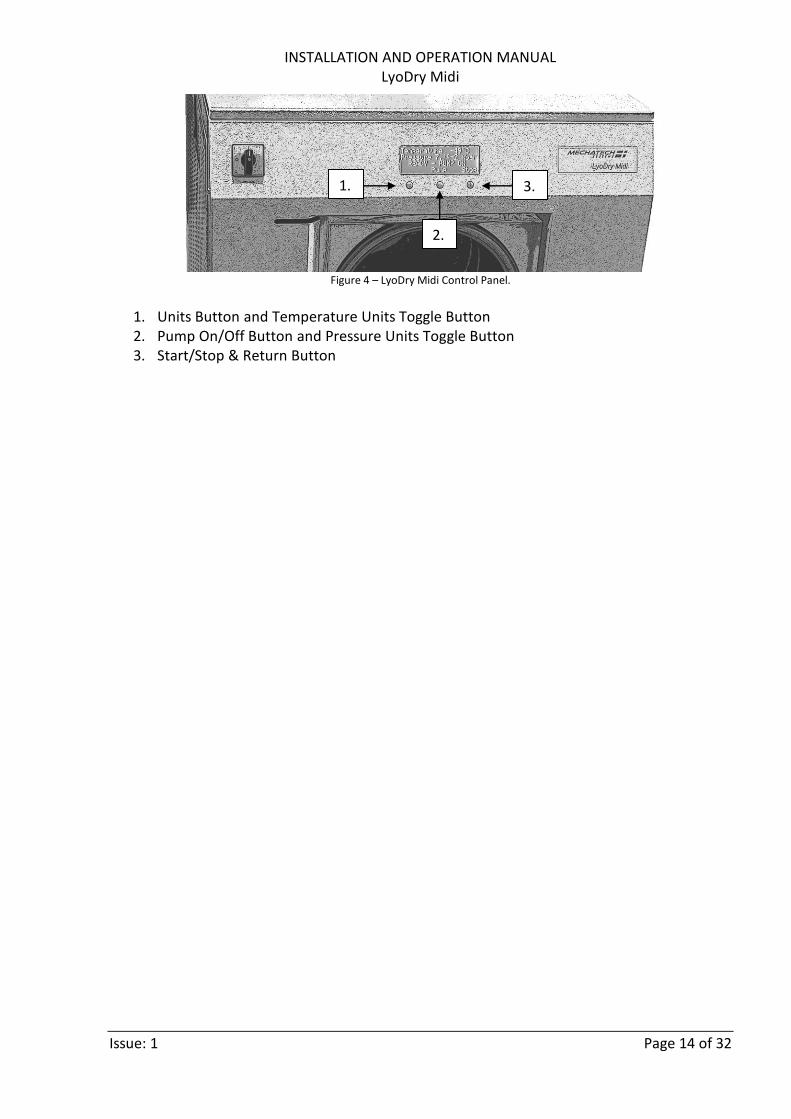
Figure 4 – LyoDry Midi Control Panel.
1. Units Button and Temperature Units Toggle Button 2. Pump On/Off Button and Pressure Units Toggle Button 3. Start/Stop & Return Button
1. 3.
2.

INSTALLATION AND OPERATION MANUAL LyoDry Midi
Issue: 1 Page 15 of 32
5. APPLICATIONS
5.1 Introduction
If you want to use the LyoDry Midi as a freeze dryer, you must connect it to a two-stage vacuum pump and fit a drying accessory. When you use the LyoDry Midi as part of a freeze drying system, we recommend that you keep accurate records of all operating parameters (that is: load, drying times, and so forth). This data will help you to determine the optimum cycle for efficient operation with various products. Some factors which affect the freeze drying process are described in the following sections.
5.2 The freezing process
You must pre-freeze the product to be freeze-dried before you place it in (or on) the drying accessory. The thickness of the ice (and hence the product) will affect the length of time needed to dry a given sample. In general, the thickness should be less than 10mm. A range of product containers is available from MechaTech Systems. These include the containers shown in Table 5.
Container Method of freezing
Bulk tray Use a cabinet freezer to freeze the bulk tray. The maximum recommended depth is 10 mm.
Vials Use a cabinet freezer to freeze the vials. The maximum recommended depth of fill is 10 mm.
Ampoules Pre-freeze in a cabinet or use a spin-freeze accessory to dry the ampoules.
Flasks Use a pre-freeze bath to shell-freeze to a maximum thickness of 10 mm.
Table 5 – Product containers
5.3 The drying process
When the LyoDry Midi is Ready (condenser has been cooling for 40 minutes and it has reached a temperature of less than -40°C, as shown on the display), the vacuum pump can be switched on. The pressure in the condenser chamber then starts to drop, producing the conditions necessary for freeze drying to occur. The pressure gauge will show the pressure in the condenser chamber. The time required to dry a product varies and is determined by a number of factors; these include the type of product, its mass and thickness, the type of container used, the temperatures of the product and the condenser and the system performance.

INSTALLATION AND OPERATION MANUAL LyoDry Midi
Issue: 1 Page 16 of 32
Freeze drying requires an input of heat energy to the product to change the ice into water vapour. When using the LyoDry Midi, this energy may be absorbed solely from the surroundings or, alternatively, a heated accessory may be used to supplement this heat input. If you use a heated accessory, the accessory should not be switched on until the pressure in the condenser chamber has fallen to 1 mbar or lower. When you decide on the quantity of heat input required, or when you try to optimise the drying cycle for a particular product, it is important to observe the physical appearance of the product whenever possible during the drying process. If the product has been correctly frozen, it will usually appear to be uniform in colour and Midi. If the product is uneven in colour, or if signs of boiling are visible, then the product may have been incorrectly frozen or may have undergone some physical change, possible from the application of too much heat. A wide range of factors has to be considered when trying to optimise the drying cycle for a given product. To assist in this optimisation, we therefore recommend that you take note of the rate of change of both temperature and pressure within the condenser chamber during the freeze drying process.
5.4 Vapour trapping
When the LyoDry Midi is used as a vapour trap, its function is significantly different to that when it is used in freeze drying applications. In vapour trapping applications, the LyoDry Midi acts solely to protect the rotary pump; in freeze drying applications, it actually pumps the water vapour from the product. In vapour trapping applications, it is often necessary to limit the vapour flow from the system to the LyoDry Midi by fitting a restrictor between the vapour source and the LyoDry Midi. The size of the restrictor depends on the system.
INSTALLATION AND OPERATION MANUAL LyoDry Midi
Issue: 1 Page 17 of 32
6. OPERATION
WARNING: If you intend to freeze dry products which contain sodium azide, make sure that your vacuum pump and pipeline are suitable for freezing these products. If they are not suitable, there is a severe risk of explosion.
Sodium azide is sometimes used as a stabilizing agent in freeze drying processes. Sodium azide is toxic and, when dry, is highly explosive. If you freeze dry a product that contains Sodium azide, a chemical reaction can occur in the presence of heavy metals such as copper, lead, zinc and cadmium. The result of this reaction is the formation of metallic azides which are highly unstable and explosive. The LyoDry Midi contains no heavy metals and is suitable for freeze drying products which contain Sodium azide.
6.1 Sequence of operation
Operation of the LyoDry Midi can involve a number of different steps:
Prepare the LyoDry Midi
Fit the product container and any other necessary accessory
Load the products
Pre-cool the LyoDry Midi
Dry the product (under vacuum)
Shut down Before you freeze a product, you must always prepare the LyoDry Midi as described. Always dry the product and shut down the LyoDry Midi as described.

INSTALLATION AND OPERATION MANUAL LyoDry Midi
Issue: 1 Page 18 of 32
However, the order in which the remaining three steps are carried out depends on the type of product container or other accessory you use and the type of product to be freeze dried. In some circumstances you will need to pre-cool the LyoDry Midi with the accessory-flange open to atmosphere; in other circumstances, you fit the product container, then pre-cool the LyoDry Midi and then load the product to be freeze dried. If the correct sequence of operations to follow is not clear to you, refer to the instruction manual supplied with the product container or other accessory which you will use.
6.2 Prepare the LyoDry Midi
CAUTION: Use only mild detergents to clean the condenser chamber, accessories and connecting pipeline. Some of the MechaTech Systems accessories are made from acrylic materials and must not be cleaned with organic solvents. Before you use the LyoDry Midi, and between freeze-drying cycles, prepare the LyoDry Midi, as follows:
1. Turn the drain-valve until it is vertical and in line with the drain nozzle to open the valve and to remove any water left in the bottom of the condenser chamber. When the chamber is completely drained, turn the drain-valve horizontal to close it.
2. If acidic or corrosive products have been processed, flush through the condenser chamber and drain-line with clean water.
3. Make sure that the condenser chamber is dry. 4. Make sure that the LyoDry Midi is clean, particularly the accessory-flange. If the flange
is not clean, you will not get a good vacuum seal and the performance of the LyoDry Midi will be poor.
5. Select a suitable drying accessory for the product. Wipe clean the sealing-ring of the accessory and check the sealing-ring for damage; if it is damaged, fit a new sealing-ring. The accessory sealing-ring should not need lubricating, but if it is excessively dry, apply a light wipe of high vacuum grease.
6.3 Fit the product container and other accessories
A drying accessory may be connected to the LyoDry Midi accessory flange. Accessories have a rubber sealing-ring to seal the accessory to the LyoDry Midi accessory flange. Once positioned, the weight of the accessory is sufficient to produce an airtight seal under vacuum conditions.

INSTALLATION AND OPERATION MANUAL LyoDry Midi
Issue: 1 Page 19 of 32
6.4 Pre-cool the LyoDry Midi
WARNING: Do not touch any part of the condenser chamber during or immediately after the cooling process. The condenser chamber is at a very low temperature and can cause tissue damage.
Note: if you cool the LyoDry Midi with no product in the chamber, the condenser temperature will cycle between approximately -40 °C and -50 °C (-75°C and -85°C on low temperature model). Pre-cool the LyoDry Midi condenser chamber as follows:
1. Switch on the electrical supply and then turn the main switch (Figure 2) to the ‘1’ (on) position.
2. The display (item 3, Figure 1) on the front panel should be illuminated. 3. Press the ‘Start’ button on the control panel. ‘COOLING’ is displayed. 4. Wait for 40 minutes. A bar graph advances from left to right indicating the timer
progress, at a rate of 2 minutes per bar. After 40 minutes ‘READY – PUMP OFF’ is displayed.
5. The temperature shown on the display should read -40°C or lower.

INSTALLATION AND OPERATION MANUAL LyoDry Midi
Issue: 1 Page 20 of 32
6.5 Dry the product
1. Switch the pump on by pressing the ‘Pump’ button (item 2, Figure 4) ‘READY – PUMP ON’ is displayed.
Take note of the following when freeze drying products:
Only switch on a heated accessory when the pressure is 1 mbar or less. When a load is first applied to the LyoDry Midi, the temperature may rise for a few minutes. This is because the evaporation rate from the product is initially high. If the temperature does not fall to -45°C or below within a few minutes (-65°C on low temperature model)
the LyoDry Midi is overloaded. Reduce the amount of product in the freeze drying system to prevent the product from melting or, when you use the LyoDry Midi as a vapour trap, restrict the flow of vapour to the LyoDry Midi.
If you wish to dry a number of flasks, first attach one flask, then evacuate the flask until the pressure (shown on the pressure gauge) falls to 1 mbar or less. Then attach and evacuate the remaining flasks in the same way. If you use this procedure, you can identify any flasks that leak. This procedure also prevents rapid pressure increases, which might cause flasks to fall off of the drying accessory.
If there appears to be a leak, check that the drain-valve is fully closed and that all seals are clean. If the LyoDry Midi continues to leak, contact your supplier.
6.6 Defrost and shut down
CAUTION: If you use a manifold assembly, do not admit air into the LyoDry Midi through the drain-valve until all flasks have been removed, otherwise the flasks may fall off the manifolds.
WARNING: Do not touch any part of the condenser chamber during or immediately after the cooling process. The condenser chamber is at a very low temperature and can cause tissue damage.

INSTALLATION AND OPERATION MANUAL LyoDry Midi
Issue: 1 Page 21 of 32
Look at the pressure shown on the pressure gauge and the appearance of the product and consult data gathered from previous freeze drying operations to determine when the freeze drying process has finished. Note that the pressure shown on the display will fall significantly when vapour is no longer being released from the product. Once the process has finished, shut down the LyoDry Midi as follows:
1. If you use a manifold accessory, use the manifold valves to vent each flask in turn. Remove and seal each flask.
2. Switch the vacuum pump off by pressing the ‘Pump’ button (item 2, Figure 3). 3. If you use other accessories, slowly open the drain-valve to admit air to the system,
turn it until it is vertical and in line with the drain nozzle. The display will now show ‘DEFROST’.
4. Remove the product when the pressure shown on the pressure gauge has reached atmospheric pressure.
5. Remove the drying accessory. 6. Leave the LyoDry Midi switched on with the drain-valve open to defrost it. 7. When the chamber is completely drained, switch the refrigeration off by pressing the
‘Stop’ button (item 3, Figure 4). 8. Close the drain valve; turn it until it is horizontal, that is, at a right-angle to the drain
nozzle. 9. Switch off the LyoDry Midi by turning the main switch (item 1, Figure 3) to the ‘0’ (off)
position. 10. Prepare the LyoDry Midi for the next operational cycle as described.
6.7 Operation with no load
If you operate the LyoDry Midi with no load for several hours, the internal components of the LyoDry Midi get very cold. Atmospheric water vapour will then condense onto the cold surfaces and may drip out of the bottom of the LyoDry Midi. You may therefore see puddles of water under the LyoDry Midi, which give the impression that water is leaking from the condenser chamber. If you see water dripping out of the LyoDry Midi, inspect the condenser chamber: if there is ice in the chamber, the water is probably not leaking from the chamber, but is dripping from the cold surfaces inside the LyoDry Midi. Always check this carefully before you contact your supplier for advice. To avoid this problem, we recommend that you shut-down the LyoDry Midi if you will not use it for three or four hours. This is particularly important if the use of the LyoDry Midi is in a high humidity environment.
6.8 Changing the temperature and pressure units
From the factory, the temperature units are displayed as degrees centigrade (°C) and the pressure units are displayed as mbar. Alternatively, the temperature can be displayed in

INSTALLATION AND OPERATION MANUAL LyoDry Midi
Issue: 1 Page 22 of 32
degrees Fahrenheit (°F) and the pressure can be displayed in Torr. The current display units are always retained when the LyoDry Midi is switched off.
6.8.1 Changing the temperature units
Change the temperature display units as follows:
1. Switch on the electrical supply and then turn the main switch (Figure 2) to the ‘1’ (on) position.
2. The display (item 3, Figure 1) on the front panel should be illuminated. 3. Press the ‘Units’ button on the control panel. 4. Press the ‘°C/°F’ button to toggle the display units between °C and °F. 5. Press the ‘Retn’ button
6.8.2 Changing the pressure units
Change the pressure display units as follows:
1. Switch on the electrical supply and then turn the main switch (Figure 2) to the ‘1’ (on) position.
2. The display (item 3, Figure 1) on the front panel should be illuminated. 3. Press the ‘Units’ button on the control panel. 4. Press the ‘mbar/Torr’ button to toggle the display units between mbar and Torr. 5. Press the ‘Retn’ button

INSTALLATION AND OPERATION MANUAL LyoDry Midi
Issue: 1 Page 23 of 32
7. MAINTENANCE
WARNING: Ensure that the electrical supply is isolated before starting any maintenance work.
7.1 Introduction
Note: you must obey the maintenance procedures defined in the instruction manuals supplied with your accessories and vacuum pump. Note: there are no user-serviceable parts inside the LyoDry Midi refrigeration system.
The following sections describe possible problems and their possible solutions and are intended as a guide to the user and to qualified service engineers. Some of the solutions can be carried out by the user, but others (which are clearly identified) must be carried out only by approved MechaTech Systems service engineers.
7.2 Calibration
It is recommended that the vacuum and temperature gauges fitted to this unit be returned to MechaTech Systems (or a relevant competent body) for service and calibration at least every 12 months. The time interval between services must to be reviewed by the customer during the units operating life.
7.3 Safety
WARNING: Obey the safety instruction given below and take note of appropriate precautions. If you do not, you can cause injury to people and damage to equipment.

INSTALLATION AND OPERATION MANUAL LyoDry Midi
Issue: 1 Page 24 of 32
7.4 Precautions
Switch off the LyoDry Midi, isolate it from the electrical supply and defrost it before you start maintenance.
Do not touch any part of the condenser chamber during or immediately after the cooling process. The condenser chamber is at a very low temperature and can cause tissue damage.
Do not pour water at a temperature greater than 50°C into the condenser chamber when it is cold. If you do, this may result in a dangerous pressure rise in the refrigeration system.
Ensure that you do fault finding in a well-ventilated area.
After you have rectified a fault, ensure that the electrical installation of the LyoDry Midi conforms to your local and national safety requirements. It must be connected to a suitable fused and protected electrical supply and a suitable earth (ground) point.
7.5 Electrical faults
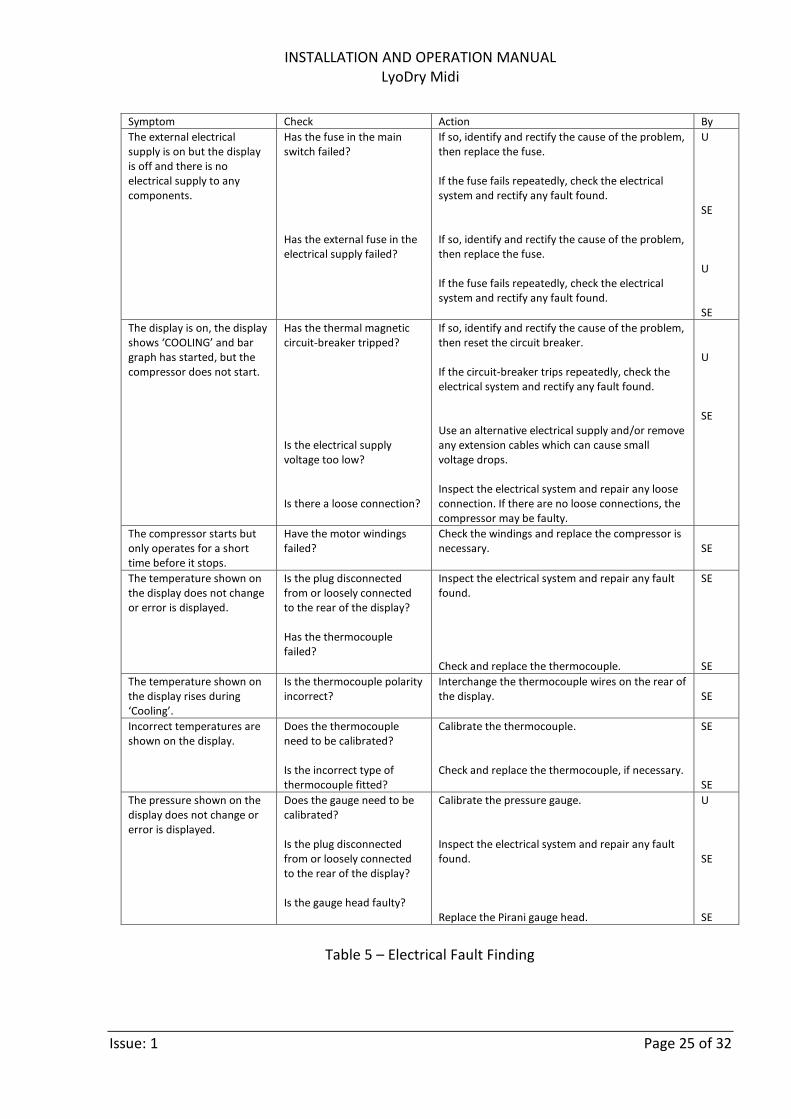
If an electrical fault is suspected, use Table 5 to identify the possible causes and actions to cure the fault. The ‘By’ column of the table identifies whether the checks and actions can be done by a user (a ‘U’ entry in the column), or whether they must be done by a qualified service engineer (an ‘SE’ entry in the column). If the fault persists after you complete the recommended action, contact your supplier before you use the LyoDry Midi again.
INSTALLATION AND OPERATION MANUAL LyoDry Midi
Issue: 1 Page 25 of 32
Symptom Check Action By
The external electrical supply is on but the display is off and there is no electrical supply to any components.
Has the fuse in the main switch failed? Has the external fuse in the electrical supply failed?
If so, identify and rectify the cause of the problem, then replace the fuse. If the fuse fails repeatedly, check the electrical system and rectify any fault found. If so, identify and rectify the cause of the problem, then replace the fuse. If the fuse fails repeatedly, check the electrical system and rectify any fault found.
U SE U SE
The display is on, the display shows ‘COOLING’ and bar graph has started, but the compressor does not start.
Has the thermal magnetic circuit-breaker tripped? Is the electrical supply voltage too low? Is there a loose connection?
If so, identify and rectify the cause of the problem, then reset the circuit breaker. If the circuit-breaker trips repeatedly, check the electrical system and rectify any fault found. Use an alternative electrical supply and/or remove any extension cables which can cause small voltage drops. Inspect the electrical system and repair any loose connection. If there are no loose connections, the compressor may be faulty.
U SE
The compressor starts but only operates for a short time before it stops.
Have the motor windings failed?
Check the windings and replace the compressor is necessary.
SE
The temperature shown on the display does not change or error is displayed.
Is the plug disconnected from or loosely connected to the rear of the display? Has the thermocouple failed?
Inspect the electrical system and repair any fault found. Check and replace the thermocouple.
SE SE
The temperature shown on the display rises during ‘Cooling’.
Is the thermocouple polarity incorrect?
Interchange the thermocouple wires on the rear of the display.
SE
Incorrect temperatures are shown on the display.
Does the thermocouple need to be calibrated? Is the incorrect type of thermocouple fitted?
Calibrate the thermocouple. Check and replace the thermocouple, if necessary.
SE SE
The pressure shown on the display does not change or error is displayed.
Does the gauge need to be calibrated? Is the plug disconnected from or loosely connected to the rear of the display? Is the gauge head faulty?
Calibrate the pressure gauge. Inspect the electrical system and repair any fault found. Replace the Pirani gauge head.
U SE SE
Table 5 – Electrical Fault Finding

INSTALLATION AND OPERATION MANUAL LyoDry Midi
Issue: 1 Page 26 of 32
7.5.1 Remove and open the inspection panels
WARNING: Disconnect the LyoDry Midi from the electrical supply before you remove the top cover. If you do not, you may accidentally touch live electrical components.
Note: Each inspection panel has an earth lead attached. You must disconnect the earth lead before you can completely remove an inspection panel. Use the following procedure to remove the side and rear panels:
1. Switch off the external electrical supply and isolate it from the LyoDry Midi. 2. Press in the top of the catch at the top-center of the right-hand panel. 3. Lift the lever of the catch to release the locking bar. 4. Pull the top of the panel out and lift the panel upwards to remove it.
Use the following procedure to remove and open the front panel:
1. Pull the handle at the top of the front inspection panel and swing the panel downwards to open it (see Figure 5).
Figure 5. Open the front panel

INSTALLATION AND OPERATION MANUAL LyoDry Midi
Issue: 1 Page 27 of 32
7.5.2 Refit the inspection panels
WARNING: Ensure that the earth (ground) cable is correctly fitted to the inspection panel. If you do not, there will be a risk of electric shock when you switch on the LyoDry Midi.
1. Place the bottom of the panel onto the two locating pins and push the top of the
panel in. 2. Push in the locking bar lever to lock the catch into place.
7.5.3 Reset the thermal magnetic breaker
Use the following procedure to reset the thermal magnetic circuit-breaker, for the refrigeration and the vacuum pump, if either has tripped. Only reset the circuit-breaker once you have identified and rectified the source of the trip.
1. Carry out the procedure in 7.5.1 above for the rear cover. 2. Press the reset button to reset the thermal magnetic circuit-breaker. 3. Carry out the procedure in 7.5.2 above 4. Refit the side cover.
7.6 Refrigeration faults
7.6.1 Repeat the installation test
If you suspect that there is a fault in the refrigeration system in the LyoDry Midi, then:
1. Defrost the chamber. 2. Repeat the installation tests. Note the results at each step and then contact
MechaTech Systems.
7.6.2 Fault diagnosis
Some possible causes of refrigeration faults, together with suggested actions to cure the faults, are shown in Table 6. The ‘By’ column of the table identifies whether the checks and actions can be done by a user (a ‘U’ entry in the column), or whether they must be done by a qualified service engineer (an ‘SE’ entry in the column). If other symptoms occur, or the cause of the fault cannot be identified, contact your supplier for advice.

INSTALLATION AND OPERATION MANUAL LyoDry Midi
Issue: 1 Page 28 of 32
7.6.3 Refrigerant leaks
The refrigerant used in the LyoDry Midi is heavier than air and is an asphyxiant by the displacement of oxygen. If a refrigerant leak is suspected, place the LyoDry Midi in a well-ventilated area. Do not allow naked flames or smoking near the LyoDry Midi, as products of combustion of the refrigerant include dangerous fluorides and chlorides. If refrigerant vapour is inhaled, summon medical help immediately. Take the victim to a well-ventilated, uncontaminated area; if the victim’s breathing is weak or has stopped, apply artificial ventilation, preferably using an oxygen resuscitator. Do not use adrenalin or other cardiac stimulants. Refrigerant in contact with skin or eyes can cause cold burns. If contact has taken place, seek medical help immediately and carry out the following: remove clothing from the affected area; carefully irrigate the affected area with tepid water for at least 15 minutes; apply a sterile dressing and treat the wound as you would a heat burn.
7.6.4 Leak test the refrigeration system
Leak test the refrigeration system with a halogen leak detector, which is sensitive to all refrigerants. Before you start leak tests, check the operation of the leak tester with refrigerant from the cylinder which you will use to recharge the LyoDry Midi. The refrigerant used in the LyoDry Midi is heavier than air, so you must check the highest joints in the system first.
7.6.5 Component replacement
Note: The refrigeration system should be left open to atmosphere for as short a time as possible.
Only replace a component when you are sure that it is the cause of the fault. Components (particularly compressors) are often replaced unnecessarily and it is therefore recommended that you recheck your findings before you replace a component. Use the following procedure to replace a component in the refrigeration system.
1. Recover the refrigerant from the system. 2. Remove the faulty component. You must use suitable pipe cutters if you cut a pipe.
If heat has to be applied to a joint, pass an inert gas through the system while you heat the joint, and again while you cool the joint.
3. Replace the component.

INSTALLATION AND OPERATION MANUAL LyoDry Midi
Issue: 1 Page 29 of 32
4. When repairs on the refrigeration system have been completed, replace the filter-dryer as that is likely to have been contaminated.
5. Dehydrate the system and recharge the LyoDry Midi with refrigerant. Before the unit is completely recharged, check that any new or repaired joints do not leak.
Symptom Check Action By
The compressor does not start.
Is there an electrical fault?
Refer to electrical faults section and rectify any fault found.
SE
The compressor starts but the temperature does not reach -50 °C (-
80°C on low temperature model).
Is there sufficient ventilation? Is there a leak in the refrigeration system?
If not, relocate the LyoDry Midi. There must be no restrictions to air-flow to the sides and rear of the LyoDry Midi. Find the leak, then repair the leak and recharge the system with refrigerant
U SE
The compressor starts but the temperature does not reduce.
Is the thermocouple faulty? Is there a leak in the refrigeration system?
Check the gauge and the thermocouple and replace if necessary. Find the leak, then repair the leak and recharge the system with refrigerant.
SE SE
The temperature rises to above -40°C during drying and does not fall to below -45°C again (-
60°C and -75°C on low temperature model).
Is the load on the LyoDry Midi too high?
Reduce the amount of product being freeze dried or restrict the vapour load to the Micro-LyoDry Midi.
U
Table 6 – Refrigeration fault finding
7.6.6 Recharge with refrigerant
If you need to recharge the LyoDry Midi due to a refrigerant leak, locate and repair the leak before you start to recharge the refrigeration system. Use the correct type and quantity of refrigerant to recharge the refrigeration system.

INSTALLATION AND OPERATION MANUAL LyoDry Midi
Issue: 1 Page 30 of 32
8. SPARES AND ACCESSORIES
8.1 General
Description Part No Supplier
Edwards APG100-XM, NW16 D026-01-000
MechaTech Systems Ltd Unit 9 Brunel Way Thornbury Bristol BS35 3UR +44 (0)1454 414723 [email protected] www.mechatechsystems.co.uk
Temperature sensor LSTC
Edwards RV12 vacuum pump A655-01-903
Edwards EMF20 outlet mist filter A462-29-000
Edwards clean application oil return kit A504-19-000
Ultragrade 19 vacuum pump oil, 4 litres H110-25-013
Dow Corning silicone high vacuum grease, 50g tube HVGREASE
Acrylic drying chamber 350mm x 435mm, lid and 2 x L-gaskets LSDC
6-tray drying assembly (for use inside acrylic chamber) LSD6
14” L-gasket for acrylic chamber L-GASKET14
Table 7: Spare Parts and Accessories

INSTALLATION AND OPERATION MANUAL LyoDry Midi
Issue: 1 Page 31 of 32
9. TECHNICAL SPECIFICATIONS
LyoDry Midi TECHNICAL SPECIFICATION
Part number and model LSMC50 LyoDry Midi
Ice removal capacity (in 12 hours) 6.0kg (13 lbs)
Ice removal capacity (in 24 hours) 10.5kg (23 lbs)
Maximum ice capacity 18.0kg (40 lbs)
Operating temperature (at 22°C ambient temperature)
-50°C +/- 5°C (-85°C +/- 5°C on low temperature model)
Temperature display range Ambient to -60 °C
Pressure display range 0.01 mbar to 1000 mbar
Refrigeration compressor type 1 hp hermetic unit (Two 1 hp hermetic units on low temperature model)
Dimensions (H x W x D) 945 x 750 x 1000 mm
Weight 230kg (507 lbs) 237Kg for low temperature model
Power requirements 230VAC/50 Hz, 13.0 A
Table 8: Technical Specification

INSTALLATION AND OPERATION MANUAL LyoDry Midi
Issue: 1 Page 32 of 32
© MechaTech Systems Ltd 2013 All rights reserved