Luxman L-100 Owner's Manual
24
Transcript of Luxman L-100 Owner's Manual


witchesControls
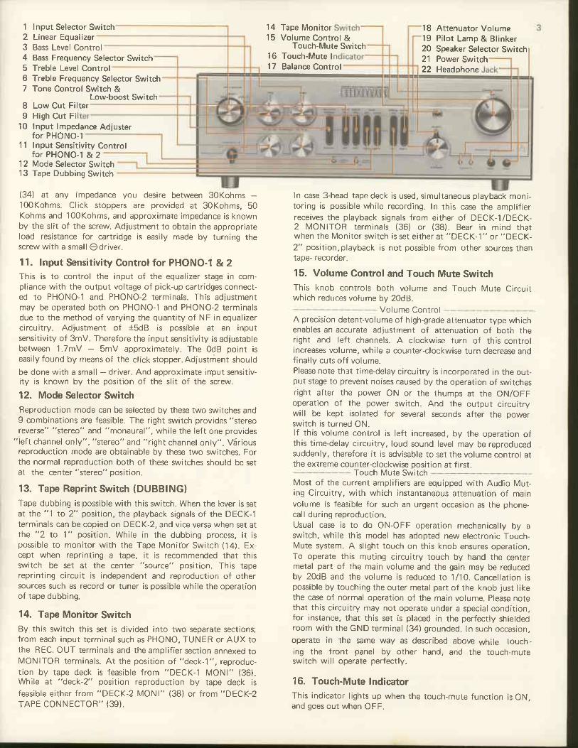
1. Input Selector SwitchThis switch allows to select desired programme source: youmay select either of 5 positions (aux-1. tuner, phono-1,phono-2, aux-2).
2. Linear EqualizerThis is a new tone control which provides a total compen-sation specially intended for subtly augmenting regular tonecontrols. With the control in its mid-position, f lat frequencyresponse is achieved. When switched to either of the 2 "up-
ti l t" positions, the entire response curve is rotated so as tolinearly increase treble response while simultaneously decreas-ing bass response Conversely selection of a "down-ti lt" posi-tion rotates the response curve in a clockwise direction andprovides a gradual decrease of treble and a simultaneousincrease of bass.This equalizer is not released even when the Tone ControlSwitch (7) is set at the "ofl" position. For further details,refer to the Operation of Linear Equalizer (Page 14).
3. Bass Level Control (BASS)
A clockwise turn of the control boosts the bass resoonse. anda counter'clockwise turn decreases and cuts the bass. This con-trol has a click stopper of 10 points for both increase anddecrease respectively. lt yields a flat frequency response whenset at the center of rotation.
4. Bass Frequency Selector SwitchBass turnover (roll-off) frequencies are selected with thisswitch When the desired frequency {150H2,300H2 or 600H2)is set by this switch, tone control operates below the selectedfrequencv.
5. Treble Level Control (TR EBLE)A clockwise turn of this knob boosts the treble resoonse.while a counter-clockwise turn decreases the treble. This con-trol has a click stopper of 10 points for both increase and de,crease respectively. lt yields flat frequency response when set
at the center of rotation
6. Treble Frequency Selec'tor SwitchTreble turnover (roll-off) frequencies are selected with thisswitch. When the desired frequency {' l .5KHz, 3KHz or 6KHz)is set by this switch, tone control operates above the selectedfreouencv.
7. Tone Control Switch & Low-Boost SwitchThis switch functions both as tone control switch whichoperates tone control function.(3) (4) (5) (6) and low-booster. lf this switch is set at "tone cont." position tonecontrol is put into operation. while at "off" position tone con-trol circuit is bv-passed. And when this switch is set at "tone
cont. & low-boost" tone control circuit and low boost circuitoperate simultaneously; you may adjust the tone controlfreely together with operation of low-boost circuit whichboosts the low frequencv below 70H2. Please note that themaximum increase point of this low-boost circuit is set at 8dB,therefore this has a shelf below 15H2.
8. Low Cut FilterWhen this switch is set at the upper positjon low frequencyrange below 70Hz can be cut off at the rate ot -12dBloct.,while at the lower position below 10Hz also at the rate of-l2dBloct. At the cenler point the fi l ter function is bv-passedto have flat frequency response; the signal wil l overrjde thiscircuit.
9. High Cut FilterWhen this switch is set at the upper position high frequenc.yrange above TKNZ can be cut off at the rate oI -12dBloct.,while at the lower position above 12KHz also at the rate of-12d8/ocl. At the center point the fi l ter function is by-passedto have flat frequency response; the signal wil l override thiscircuit.10. Input lmpedance Adiuster for PHONO-1You may set this input lmpedance Adjuster for pHONO,l
I23
6
67
Iq
1 0
Input Selector SwitchLinear EqualizerBass Level ControlBass Frequency Selector SwitchTreble Level ControlTreble Frequency Selector SwitchTone Control Switch &
Low-boost SwitchLow Cut FilterHigh Cut FiInput lmpedance Adiusterfor PHONO-1
1l Input Sensitivity Controlfor PHONO-I & 2
12 Mode Selector Switch13 Tape Dubbing Switch
{34} at any impedance you desire between 3oKohms -100Kohms. Click stoppers are provided at 3oKohms,50Kohms and 1ooKohms, and approximate impedance is knownby the slit of the screw. Adjustment to obtain the appropriateload resistance for cartridge is easily made by turning thescrew wi th a smal lOdr iver .
11. Input Sensitivity Control for PHONO-I & 2This is to control the input of the equalizer stage in com-pliance with the output voltage of pick-up cartridges connect-ed to PHONO-1 and PHONO-2 terminals. This adjustmentmay be operated both on PHONO-1 and PHONO'2 terminalsdue to the method of varying the quantity of NF in equalizercircuitry. Adjustment of isdB is possible at an inputsensitivity of 3mV. Therefore the input sensitivity is adjustablebetween 1.7mV - 5mV approximately. The odB point iseasily found by means of the click stopper. AdjustmenL shouldbe done with a small - driver. And approximate input sensitiv-ity is known by the position of the slit of the screw.
12. Mode Selector SwitchBeproduction mode can be selected by these two switches andI combinations are feasible. The right switch provides "stereo
reverse" "stereo" and "monaural", while the left one provides"left channel only", "stereo" and "right channel only". V5rious
reproduction mode are obtainable by these two switches. Forthe normal reproduction both of these switches should be setat the center "stereo" position.
13. Tape Reprint Switch (DUBBING)
Tape dubbing is possible with this switch. When the lever is setat the "1 to 2" position, the playback signals of the DECK-lterminals can be copied on DECK-2, and vice versa when set atthe "2 to l" position. While in the dubbing process, it ispossible to monitor with the Tape lvlonitbr Switch (14). Ex,cept when reprinting a tape, it is recommended that thisswitch be set at the center "source" position. This tapereprinting circuit is independent and reproduction of othersources such as record or tuner is Dossible while the ooerationof tape dubbing.
14. Tape Monitor SwitchBy this switch this set is divided into two separate sections;from each input terminal such as PHONO, TUNER or AUX tothe REC. OUT terminals and the amplif ier section annexed tol\ i lONlTOR terminals. At the position of "deck-1", reproduc-t ion by tape deck is feas ib le f rom "DECK-1 MONI" (36) .While at "deck-2" position reproduction by tape deck isfeasible either from "DECK-2 lVONl" {38) or from "DECK-2
TAPE CONNECTOR" (39).
Tape Monitor Attenuator VolumePilot Lamp & BlinkerSpeaker Selector Switch
Touch-Mute I Power SwitchBalance Control Headphone
ln case 3-head tape deck is used, simultaneous playback moni-toring is possible while recording- In this case the amplif ierreceives the playback signals from either of DECK-l/DECK,2 MONITOR termina ls (36) o r (38) . Bear in mind tharwhen the [.4onitor switch is set either at "DECK-'1" or "DECK-
2" position,playback is not possible from other sources thantape- recorder.
15. Volume Control and Touch Mute SwitchThis knob controls both volume and Touch l\,4ute Circuitwhich reduces volume bV 20d8.
Volume ControlA precision detent-volume of high-grade attenuator type whichenables an accurate adjustment of attenuation of both theright and left channels. A clockwise turn of this controlincreases volume, while a counter,clockwise turn decrease andfinallV cuts off volume-Please note th3t t ime-delay circuitry is incorporated in the out-put stage to prevent noises caused by the operation of switchesright after the power ON or the thumps at the ON/OFFoperation of the power switch. And the output circuitrywill be kept isolated for several seconds after the powerswitch is turned ON.lf this volume control is left increased, by the operation ofthis time-delay circuitry, loud sound level may be reproducedsuddenly. therefore it is advisable to set the volume control atthe extreme counter-clockwise position at f irst.
Touch N4ute SwitchMost of the current amplif iers are equipped with Audio Mut-ing Circuitry, with which instantaneous attenuation of mainvolume is feasible for such an urgent occasion as the phone-call during reproduction.Usual case is to do ON-OFF operation mechanically by aswitch, while this model has adopted new electronic Touch,l\,4ute system. A slight touch on this knob ensures operation.To operate this muting circuitry touch by hand the centermetal part of the main volume and the gain may be reducedby 20dB and the volume is reduced to 1/10. Cancellation ispossible by touching the outer metal part of the knob just l ikethe case of normal operation of the main volume. Please notethat this circuitry may not operate under a special condition,for instance. that this set is placed in the perfectly shieldedroom with the GND terminal {34) grounded. ln such occasion,operate in the same way as described above while touch-ing the front panel by other hand, and the touch-muteswitch wil l operate perfectly.
16. Touch-Mute IndicatorThis indicator l ights up when the touch-mute funcrion is ON.and goes out when OFF.
1 4t 5
1 81 9202 1
Volume Control &Touch-Mute Switch
t o1 7

17, Balance ControlThe volume balance on right and left channels can be adjustedwith this control. Turn it clockwise. and the volume of theleft channel wil l decrease {max:-14dB); counter-clockwise turncauses decrease of the right channel. When the volume oJ bothchannels is balanced, monaural reproductlon sound comesfrom the center of both right and left speakers. This point iseasily lound by the click-stopper at its center point.
18. Attenuator VolumeOccasionally a fine adlustment of volume control may notbe easy when low level reproduction is needed; in case ofover-rated input at the input terminals or the mid-nightl istening- In such cases, the adjustment by the attenuatorvolume makes it easy when it is operated after the roughleve l j s se t by the vo lume cont ro l { i5 ) .Full clockwise turn is equivalent to 0dB, that is, not attenuat-ed, the position of which may be used for measurement orfull-gain operation. While a counter-clockwise turn decreaseslevel. and the full turn attains -20d8 attenuation.Thus free preset of the maximum point of the volume isfeasible between odB and -20d8 bv the adiustment of thisattenuator volume.
19. Pilot Lamp and BlinkerA time-delay circuitry to mute the PRE. OUT lerminals andREC. OUT terminals is provided to prevent the thump noisesat the time of the operation of switches right after the poweron or at the ON-OFF operation of the power switch. There-fore, output terminals are muted by this time-delay circuitryfor several seconds after the power switch is ON. The pilotlamp keeps blinking while the time-delay circuitry is underoperation. and wil l l ight on and stop blinking when normaloperation is allowed-
20. Speaker Selector SwitchThis amplif ier offers convenient use of 2 speaker systems. Youcan choose independent or simultaneous driving of I or 2
systems. When the A button is pressed in, the speaker ter-minals A (26) wil l operate and the B button is for the termi-nals B (27). When both of the A and B buttons are pressed in,the A and B terminals wil l operate at the same time. In thiscase, make sure that the overall impedance is not less than 4ohms.21. Power Switchlvlains power is turned on when this switch is pushed, and thepilot lamp begins to blink for a several seconds unti l this set isin perfect operational condition. And the next push shuts offrne matns power.
22. Headphone JackConnection of a sterephonic headphone to this jack allowsprivate l istening. Output signals are always available regardlessof the position of the Speaker Selector Switch \2O). Forstereophonic reproduction, however, it is recommended to setthe soeaker sw i tch a t rhe Ot I pos i t ion .
23. 24. Extra Mains OutletConvenient for supplying mains power to outer equipmentsuch as Al\.4/Flvl tuner or record plaver. The terminals (24SWITCHED) are indeoendent of the mains switch of theampl i f ie r , wh i le the o ther {23 UNSWITCHED} is coup led w i ththe mains switch (21).The supply of the mains power dependson themains swi tch .The to ta l capac i ty fo r the UNSWITCHEDterminals is 200W. and the SWITCHED is 100W.
25. Power Supply CordPlug in the end o{ this cord to the wall socket of 120 V A.C.
26. 27. Speaker Terminals(A and B)The soeaker svstems should be connected to these terminals.These terminals are coupled with the speaker switches, and thespeaker switch must be set at the position corresponding tothe terminal to which the speaker systems are connected- (26)
Extra AC Outlet (UNSWITCHED)Extra AC Outlet (SWITCH ED)Power Supply Cord
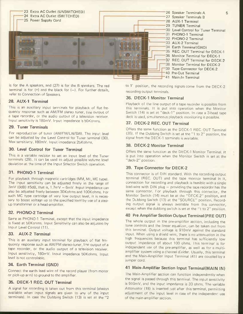
is for the A speakers, and l27l is tor the B speakers. The redterminal is for (+) and the black for ( ). For iurther details,refer to Connection of Speakers.
28. AUX-I TerminalThis i s an aux i l ia ry input te rmina ls lo r p layback o f f la t f re -quency response such as AM/FM stereo tuner, l ine output ofa tape recorder, or the audio output of a television receiver.Input sens i t j v i t y i s '180mV. lnput impedance is 50Kohrns .
29. Tuner TerminalsFor reproduction of tuner (AM/FN4/LWSW). The input levelcan be adjusted by the Level Control {or Tuner terminal (30).\ ,4ax sens i t i v i t y , 180mV. Input impedance 25Kohms.
30. Level Control for Tuner TerminalThis is a variable resistor to set an input level of the Tunerterminals (29). lt can be used to adjust possible volume leveldeviation at the time of the lnput Selector Switch operation.
31. PHONO-1 TerminalFor playback through magnetic cartridges (l\41\,4, N4l, N/lC type).The input sensitivity can be adjusted freely in the range of3mV (OdB) t5dB, tha t i s , 1 .7mV - smv Input impedance canalso be adjusted freely between 30Kohms and i00Kohms. Forsuch l\,4C type cartridge of very low output level, it is necessary to boost voltage up to the specified level by use of a step-up transtormer or a head-amplif ier.
32. PHONO-2 TerminalSame as PHONO-1 Termina i , except tha t the input impedanceis f i xed a t 50Kohms. Input Sens i t i v i t y can a lso be ad jus ted byInput Leve l Cont ro l ( '1 1 ) .
33. AUX-2 TerminalThis i s an aux i la ry input te rmina l fo r p layback o{ f la t f re -quency response such as AlVl/Fl\,4 stereo-tuner, l ine output of atape recorder, or the audio output of a television receiver.Input sens i t i v i t y , 1BomV. Input impedance 50Kohms. Inputlevel is not controlable.
34. Earth Terminal (GND)Connect the earth lead wire of the record player {from motoror p ick -up arm) to g round to the ampl i f ie r .
35. DECK-1 REC. OUT TerminalA signal for recording is taken out from this terminal (alwaysavailable when input signals are given to any of the inputte rmina ls ) . In case the Dubb ing Swi tch {13) i s se t a t the "2
3637
Speaker Terminals A 5Speaker Terminals BAUX-1 Termina lTUNER Termina lLevel Control for Tuner TerminalPHONO- l Termina lPHONO-2 TerminalAUX-2 TerminalEar th Termina l {cND)REC. OUT Terminal for DECK-1Monitor Terminal for DECK-1REC. OUT Termina l fo r DECK-2l\4onitor Terminal for DECK-2Tape Connector for DECK-2Pre-Out TerminalMain . ln Termina l
404 1
to 1 ' pos i t ion , the record ing s igna lscome f rom the DECK-2recordrng output terminals.
36. DECK-1 Monitor TerminalPlayback oi the l ine output of a tape recorder is possible fromth is te rmina ls . l1 i s pu t in to opera t ion when the N lon i to rSwi tch {14) i s se t a t "deck-1" pos i t ion . In case a 3 head tapedeck is used, s imu l taneous p layback mon i to r ing is poss ib le .
37. DECK-2 REC. OUT TerminalOffers the same func t ion as the DECK- l REC. OUT Termina l(35) . l f the Dubb ing Swi tch is se t a r the " l to 2 , ,pos i t ion_ thes igna l f rom the DECK- 1 te rmina ls i s ava i lab le .
38. DECK-2 Monitor TerminalOffers the same func t ion as the DECK-1 l \4on i to r Termina l . l tis put into operation when the lvlonitor Switch is set at the"deck-2" position.
39. Tape Connector for DECK-2This connector i s o f D IN s tandard . Wi th the record ing ou tpu tte rmina l (BEC. OUT) and the tape mon i to r te rmina l in i t .connection for recording and playback is feasible with a singlelead-wire with DIN plug - providjng the tape recorder has thesame connector. For playback through this connector, thel \ lon i to r Swi tch ( i4 ) musr be a t the "DECK 2" pos i r ion , andthe Dubb ing Swi tch ( '13) a t the "SOURCE" pos i t ion . Record ,ing output signal is always available from this connector,except when the dubbing switch is set at the "j to 2" positjon
40 Pre Amplifier Section Output Terminal(pRE OUT)The who le ou tpu t in the pre-ampl i f ie r sec t ion , inc lud ing thetone controls and the l inear equalizer, can be taken out fromth is te rmina l . Outpu t vo l tage is 91omV aga ins t the s tandardinput . When us ing a sh ie ld w i re . there is no a t tenuat ion in thehigh frequencies because this terminal has sufficiently lowoutput impedance of about 100 ohms. This terminal is iorindependent use of the pre-amplif ier, as well as for a multi-ampl i f ie r sys tem us ing a channe l d iv ider . Usua l lv , th is te rmina land the l \ y 'a in -Ampl i f je r Input Termina l (41) a re couo led bV aiu moer cord.
41 Main-Amplifier Secrion Input Terminal(MAIN lN)The l\y'a in-Amplif ier section can function independentlv whenthe signal is passed through this terminal The input sensitivityis 91omV, and the input impedance is 33 ohms. The var iab leAt tenuator ( i8 ) i s inser ted jus t a f te r th is te rmina l , permi t t ingadjustment of the input level in case of the independent useof the main-amplif ier section.
262l2829
23
25

ircuitry
r Equalizer Stage
A Cascoded D i fJeren t ia l D i rec t Coup led Ampl i l ie r i sadoptedThis dilferential circuitry at the top stage stabil izes the directcoup led s tage and he lps ob ta in be t te r l inear i ty . A lso th issh ie lds the NF amp immune f rom the ex ter io r e f fec ts such ascar t r idges to be connected to the input . Good l inear i ty , s tab i -l i ty and SN ratio are ensured thanks to the Cascoded Amplif ier adopted for this dif ierential stage and the Jol owing stage.As for the output stage, the adoption of the transistor of TO 5type a t the f ina l s tage together w i th the push pu l l c i rcu l t ry byClass A Inver ted Dar l ing ton Conf igura t ion permi ts to acceptthe low impedance loads. This is designed {or the prolessionaluse because current slandard control amps cannot stand the severe load cond i t ion a t equa l izer s tage when a lo t o f l ines o frecording output is used frequently with professional equip-ment . Constan t Cur ren t C i rcu i ts a re adopted a t impor tan tpoints to improve the l inearity of the transistor itself, theopen loop ga in and the d i f fe ren t ia l func t ion , a l l o f wh ich
BLOCK DIAGRAIVI for EOUALIZER STAGE
cont r ibu te to lower the d is to r t ion .The permiss ib le input vo l tage a t PHONO termina ls i s420mV a t l KHz (R.N,4 .S Input Sent i t i v i t y OdB) . R. l .A .A.equa l iza t ion is w i th in 102d8, wh ich is rea l i zed by care fu lseJection of the components used in this equalizer stage. Otherfunctions related to this stage are Inpul Sensitivity Adjuster,Input l rnpedance Ad jus ter and L inear Equa l izer .
*lntermediate Amp & Tone Control Circuitry
These two stages adopt cascoded direct-coupled amp toimprove l inear i ty espec ia l l y a t h igh l requency range, and s tab i -l i t y and SN ra t io a re jus t the same wi th tha t o { the equa l izersrage_Constant Current Circuitry is adopted in the output stageto improve linearity of the transistor itself and the openloop ga in . Phase compensat ion fo r NF s tab i l i za t ion is jus tone, and the aggravat ion o f the d is to r t ion a t h igh f requencyrange is a lmost n i l .Tone cont ro l c i rcu i t rv o f LUX or ig ina l NF type improvesthe distortion together with the above mentioned amplilyingc i rcu i t ry . Tone Cont ro l iunc t ion is p rov ided w i th independentf requency se lec tor w i th 3 po in ts fo r bo th bass (150H2, 3O0Hz,600H2) and t reb le (1 .5KH2, 3KHz, 6KHz) together w i th thetone de fea t sw i tch . Th is c i rcu i t ry a l lows iow boos t a t thesame t ime. Thus a w ider tona l ad jus tment i s feas ib le .Fur ther a de ten t -vo lume o f 21 po in ts i s adopted fo r bo thbass and treble level controls. This is lust the sanre type withthe high-grade attenuator, which prevents gang error betweenr igh t and le f t channe ls .
*Buffer CircuitryEmitter follower circuitry is adopted for this stage. But thisis somewhat dif{erent Jrom the ordinary one. Here twotransistors are used; one is {or the emitter follower and theother for the constanl current circuitry to the emitter lollowerstage. This constant currenl driving circuitry ensures nol onlykeeps good linearity of the transistor itself but suppress the

BLOCK DIAGRAM
L g
E S
distrotion owest for wide frequency range by means of itsh igh open loop ga in .
* Filter Circu it
Th is s tage is an NF type u t i i z ing ern i t te r Io l l6wet 2 t rans is to rsare used to r th is c i rcu i t ry ; one is fo r emi t le r fo lower and theother i s fo r the cons tan t cur ren t d r iver c i rcu i t ry . C ! t o f ft requencv can be se lec ted e i ther a t 10Hr ( 18dB/oc t . ) o r 70Hz( '12dBloc t . ) fo r Bass cu t and TKHz ( 12dBloc t . ) o t l2KHz| 12dB/oc t . ) fo r Treb le cu t . Independent f l te r c i rc ! i t s lo reach cut off frequency are provided, and these cut off polntscan be se lec ted by the who le swi tch ing o f the c i rcu l t ry Ofcoorsc no s rgna ls w I go r rougr r these c rcu t r es when thet i l te r sw tch ls o f {
Power Amplif ier Section:
Thls section adopts d rect coupled pure cornp enlentary OCLc l rcu l t ry wh ich is composed bV cascoded d i fJeren t ia l a rnp i f ie rs tage, emi t te r fo l lower s tage, co .np lementary d r iver s tage, andt ina l s tage.The s lgna ls supp l ied to the MAIN N te rmlna ls f low to thecascoded d i f fe ren t ia l ampl i f le r wh ic l r i s a k ind o f the ba ancedDC amp i fy ing c i rcu i t , where vo l tage ampl i f i ca t lon ls rnadeTh is d i l fe ren t ia l a rnp i f ie r i s des igned to be qu i te s tab e aga ins tthe f luc tua t ion o f the mains vo tage or the ambien t te r rperature. Tl-re two transistors for the l irst differenlial stage arear ranged qLr le symmet r ica l l y ; one is fo r the input s lgna ls aodthe o ther i s fo r the leedback s igna s . When sonte po ten t la lhappcns to appear a t the ou tpu t te rmina ls , th is i s ead backi - l r o I l ^ C f i r s l d i ' f e ' p n t ' a . t d g e v i d t l . . . * d L d . I r r i r r n c . 1
the ba lanced 0 po ten t ia l cond i t ion together w i th the secondd i f fe ren t la l a l r rp l i f ie r . The second d i f fe rcn t ia l amp is des iqnednot to be perlectly symmetrical but its operation is lhe sarriew i th the t i rs t s tage. The second s tage is d r lven by cons tan tcur ren t to r the vo l tage arnp l l f i ca t ionIn between the cascoded d fferential arnp staqe of Cass Aopera t ion , and the ou t l lL t t s tage ( the conrp le r r len tary d r iver
s tage and the f ina l s tage) o f C iass B, the ern l t te r fo l lowers tage made up o f 2 t rans is to rs (one is fo r the emi t te r fo owerand the o ther i s lo r the cons tan t cur ren t d r iver fo r the emi t te rfo l lower c i rcu i l ) i s a r ranged to p revent the pre-dr lver s tagel rom the impedance f l l c tua t ion ca lsed by speaker loads byrnsu la t ing the d i f fe ren t la i a |np l i f ie r s tage f rom the ou tpu tstage. Therefore, f lat negative feedback is possib e from lowTrequency range to h lgh f requency range, and s tab le und is to r ted dr iv lng is n rade feas ib le w i t l . r a s l ighr phase com-pensa l ronFor the outpLrt stage, a pore cornplementary push,pLr I circu i t ry composed by NPN power t rans ls to rs and PNP ones,wh ich are o f sy rnr re t r l ca l charac ter is t i cs . In o rder to ob ta ln ab lg power o i 110W per channe l in to B-ohm oads, bo thchanne ls d r iven , 4 power t rans is to rs des igned fo r b ig -o ! r tp l r tuse are arranged at the final stage to se1 up the parallepush pu l l connect ion to t l ' l e d r lver s ta l te Th is improves thed is to r t ion charac ter is t i cs by means o f the marg in ob ta jned bythe ncrease o t lns tan taneous co l iec to r d iss lpa t lon and l l tee f fec t i ve usage o f the good inear i tV por t ion ln the h fe - jccharacterlst cs o{ each power transistor Of course transistors01 super io r l lnear i ty a re se lec ted fo r the complementary d r ivc rs tage. There fore the power ampl i f ie r sec t ion ensures qoodstab i l l t y and exceed lng ly f lne c l ra rac ter is t i cs th roughout a l ithe stages.
Mains Power Supply Section:I t i s p robab le tha t the t luc tua t ion o f the opera t ion o f bo th thepre-ampl i f ie r sec t ion o f the C lass A opera t lon and thc d i f fe ren-t ia ampl i f ie r s tage in the rna in ampi i f ie r sec t ion tends toproduce l . i \4 d is to r t ion To prevent th is , th is a r rp adopts reaAutor ra l i c Vo l tage Regu la to r (AVR) to supp ly rna ins powerto tl 're C ass A operation stage, and perfectly separates thewind ings in the power t rans fornrer fo r the C iass A opera t ionand to r the C lass B opera t ion . Fur lher the e lec t roy t i ccapac i to rs o f 15 ,000uF x 2 a re used ln the power supp ly c i rcur t ry to r the ou tpL t t s tage in the main ampl i f le r sec t on toachieve the best perforrnance

onnectionFrocedure
Connection to Input Terminals:
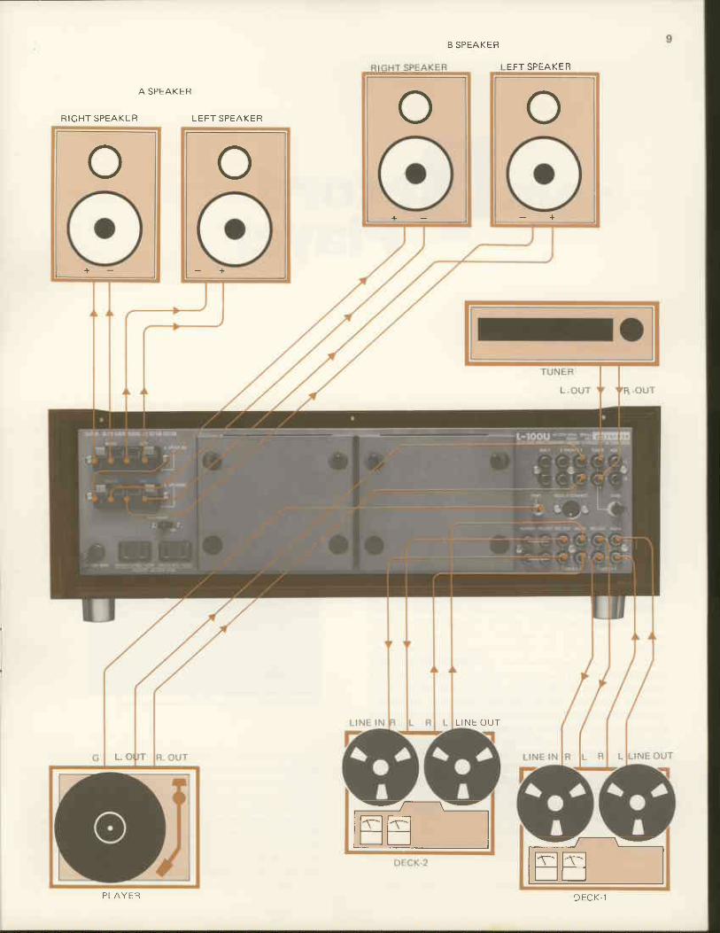
Connect the outputs of player, tuner, or tape-recorder to therelevant input terminals of this amplif ier. As to the details, seethe section on Playback of Disc, Tuner and Tape recorder.
Connection Cable (Cord Wire):For connection of the record-player, tuner, and tape-recorder,shield wire is advisable to use for protection from externalno ise or induc tance no ise Usua l ly , th is sh ie ld w i re has thecapacitance of approx. 2O0pFlm, and even so called lowcapa-c i tance sh ie ld w i re has 100pF/m, i .e , the adopt ion o f aconnection cable gives the same effect as that of the insertionof a capacitor in parallel with input sources or output loadequ ipment (wh ich composes a k ind o l h igh-cu t i i l te r c i rcu i t ) .For instance 2 meters of this shield wire has 400pF caoacitance, and ii this cord is used at the point where parallel com-posite value of input and output impedance is 500Kohms, itmeans an insertion of a high-cut t i l ter with cut-off irequencyat about l0KHz, which causes unnecessary attenuation of thehigh frequency range. Use of the shortest wire is, therefore,recommended, especially ior high impedance equipment.Choose a shield wire of good quality and make it as short asposs ib le fo r connect ion oJ th is ampl i f ie r (a t PHONO, AUX,Tape-monitor, tape jacks etc.) with the high impedance equip-ment ln case input or output impedance is sufficiently low,the efJect is not much, since parallel composite impedancebecomes lower and cut-off frequency wil l be shifted out of theaudible range. lt does not matter if relatively long cable is usedfor terminals, since their impedances are so designed as to besuf f i c ien t ly low (approx- 100 ohms) .
Connection of Speakers:Stereophonic playback is made with a pair of speaker systemsfor right and left channels. The right speaker system should beconnected to the right speaker terminals, and the lett speakersvstem to the left terminals.Note that perfect sound reproduction cannot be expected if
the phase is not matched between both channels. To match thephase is to connect the (+) terminal of the right speaker to the(+) te rmina l ( red cap) in the r igh t channe l o f power ampl i f ie r ,and the ( - ) te rmina l to the ( - ) one (b lack cap) . Do the samewith the left speaker. lf mismatched Jor some reason (e.9., mis'connection of speakers), the low frequency range is subduedand stable olavback cannot be realized.To l i rm ly connect the speaker te rmina ls , s t r ip o f f the end o fthe sh ie ld w i re by 1omm and inser t i t in to the te rmina l ho leby pressing the terminal head, and then releasing it.
Connection of Mains Power Supply Source:As the final step of preparation, connect the amplif ier to themains power supply source. Connect the power cord (25) tothe power supply outlet. Then press the power switch (21).The pilot lamp (19) begins to blink for several seconds andlight up finally when all the circuitry is put into operationalcond i t ion .
EFT SPEAKEB
B SPEAKER
A S P E A K E R
R I C H T S P E A K L B L E F T S P E A K I R
L I N E O U T
o o- +
o+ -
o
-zl-------\'--
ll-r_-llFl Ilfr rr I -/-------\'--
tmla.r IlE f r I
D E C K - 1P L A Y E R

1 0
cordPlayer
Connections:The plaver has 2 cords with pin-plugs at their ends for bothright and left channels. Connect the pin-plugs to the inputterminals of this amplif ier [PHONO-1 (31), PHONO-2 (32)].
The player's earth lead can be connected to the GND terminal(34). The player's powerflex can be connected to the extrapower outlet (23) (24) of the amplif ier.This amplif ier is provided with 2 input terminals (PHONO-1
& PHONO-2) to be selected by the input selector switch (' l).
This is useful for comparison or using two record players. Foruse of one player, either of the two input terminals can beselected. But in case lvlM-type cartridge (Moving l\4agnet) isused, its impedance can be varied (using the impedance adjust-or) to give a proper load to the cartridge.
Signal Paths:First, the signals fed to the amplif ier through PHONO termi-nals are brought to the equalizer section, where recordedsignals are restored to the original frequency curve. Incidental-ly. this equalizer curve has been standardized to the RIAAcurve. The equalized signals are then fed to the input selectorswitch {function switch) via Linear Equalizer stage. lf thisswitch is not set at PHONO positlon, the signals are blockedhere and no amplif lcation is possible. After input selector, oneline goes to the REC. OUT terminal, and the other to the tapemonitor switch. If the lvlonitor Switch {'14) is set at the"SOUBCE" position, the signals are sent to the mode selectorswitch, balance and volume controls, but if at the "DECK-l"
or "DECK-2" position, the signals are stopped at the tapemonitor terminals, Except during tape playback the monitorswitch must be kept at the "SOURCE" position. But when theinput signals are fed to PHONO or AUX terminals, recordingoutput is always obtainable regardless of the position of themonitor switch. Then the signals are sent to the volume con-trol through the mode selector and balance control.
Such controls as Linear Equalizer, Low-cut f i l ter, High-cut
filter, Attenuator, Low booster, and Tone Controls are forflexible and diversif ied adjustment of playback sound and donot block the signals completely. When the PRE. OUT termi-nals and the MAIN lN terminals are connected by us€ of thejumper metals, signals, via attenuator are voltage-amplif ied atthe main amplif ier section and flow to the Speaker SelectorSwitch. When this switch is set at the corresponding positionto the terminals the speaker systems are connected to, thesignals can be reproduced through the speaker systems. As forthe easy understanding of the signals paths, please refer to theblock diagram on P.7.

uner
Playback:Put a disc on the turn-table for playback. As the volume con'trol is turned clockwise, playback sound comes from thespeakers. As explained above, playback is possible regardlessof the position of the Mode Selector, etc. Input SelectorSwitch (1), l\,4onitor Switch (14), Speaker Switch (20) andVolume Control (15) should be set at the correct positions.
After all preparations are completed, check if the volumelevels on both right and left speakers are identical. lf different,adjust them with the Balance Control. For Stereophonic play-
back, set the l\,4ode Selector Switch (12) to the STEREOposition.
Playback from Tuner:
Connect the tuner's output terminals (leftand r igh t ) to the ampl i f ie r ' s TUNER termi -na ls (31) . The Input Se lec tor Swi tch (1 )must be set at the TUNER position. Asshown in the block diagramme, the inputsignals from the tuner are fed directly to theinput selector circuit. Afterwards. the signalstrace the same blocks as are explained in theTAPE DECK section and are reproducedfrom the speaker systems. Both for FlVl ste-reophonic and monaural broadcasing, thelvlode Selector Switch should be set at the STEREO position,for such accommodation to the input source can be made inthe tuner. lvlodulation hum in the ANy' programme can be elimi-nated by varying the distance and angle of these components.
Input Level Control:Each te rmina l o f TUNER, AUX- I and AUX-2 is the inputterminals of f lat frequency response. For the TUNER ter-minals (29), the lnput Level Control (30) is provided.Input sensitivity of 180mV is obtained by the extreme clock-wise turn of this control. This is variable in the range below180mV by turning this control to cou nter-clockw ise directionTo obtain the matching level between the TUNER terminalsand the ghono terminals, this control is useful. When 2 tunersor a tuner and one set of any other audio equipment aredesired, the level between those two equipments may easilybe ad jus ted by us ing TUNER termina ls and AUX-1 te rmina ls

Playback from Tape Monitor Terminals:
Almost all tape-recorders and tape-decks currently marketed include anequalizer amplif ier in their circuitry,and some tape-players are made ex-clusively for playback.Connect the output terminal (LINEOUT) to the Tape Monitor terminals(36) & (38). Then set the MonitorSwitch (14) at the correspondingposition to which the tape-recorderis connected. lf two tape-recordersare connected to the terminals (36)and (38), selection between either oftwo units is possible by the Tapelvlonitor Switch (14).
When the Tape lvlonitor Switch ('14) is set at "SOURCE"
position, signals before recording are reproduced. and at"DECK-'1" or "DECK-2" position the signals recorded on eachtape deck can be reproduced- Therefore, a 3-head tape deckmakes it feasible to have playback while recording.Note that a normal function cannot be expected lf 2 sets oftape-recorders for playback are connected to the terminals ofDECK-2 (38), and Tape Connector (39) at the same time,since thes€ two are coupled in the inside circuit and affect eachother. Therefore, if the Tape Monitor terminals and the TapeConnector are used, the tape-recorders should be connected tothe terminals of DECK-1 IVIONITOR terminals (36) {with theMonitor Switch at the Deck-1 position) and to the TapeConnector for DECK-2 (39).
Playback from AUX Terminals:Playback of tape is possible if the l ine output of the tape-recorder or tape-deck is connected to the AUX terminals ofthis amplif ier by use of a pin-jack lead, and the Input SelectorSwitch (1) is set at the position coresponding to the AUXterminals. All ooerations in this case are the same as those for
the p layback f rom tuner {P . l i ) .Note that when tape playback is made through the AUXterminals or TUNER terminals, the l ine input or AUX inputterminals of the tape-deck should be kept free. lf connected tothe Recording Output terminals (REC. OUT) of the amplif ier,there wil l be possible oscil latron by feed-back of signals.
Playback from Tape Connector:Thls is a connector of DIN standards and is convenient for sim-ple connection with a patch cord between the tape-recorderand recording playback connectors of this amplif ier. Playbackof deck from the Tape Connector is possible if the lvlonitorSwitch is set at the DECK-2 position when the DIN connectoron the tape deck is connected to the DECK-2 tape Connector(39) on this set.
Recording on Tape:In case of playback of varlous programme sources throughinput terminals of this amplif ier, the same signals as thosereproduced in the speakers are always available at the REC.OUT terminals (35. 37) and the Tape Connector (39). Butplease note that no signal may be available on the REC. OUTterminals according to the position of Tape Dubbing SW (13),e.9., when the Tape Dubbing switch is set at "1 to 2" posltlon,no signal is at DECK-2 REC. OUT Terminals.By connecting these terminals to the input terminals (AUX orLINE lN) of the tape-recorder, you can enjoy simultaneousrecording and playback. (lt is recommended that the DubbingSwitch can be kept at the SOURCE position). These recordingsignals are taken out before the tape monitoring stage, andthere is no infiuence fromthe Filteryolume or Tone Controls,etc. as far as the quality of the recorded signal is concerned.
Tape Dubbins (REPRINTI NG) :With this amplif ier, it is possible to reprint from one tape-recorder to another. Connect the l ine output terminals and theline input (or AUX) termjnals of one tape-recorder to the

DECK-1 L4on i to r and REC. OUT te r -minals of the amplif ier respectively.Likewise, connect the l ine input andoutput of the other tape-recorder tothe DECK-2 terminals. Dubbing isnow possible by use of the DubbingSwitch. At the " l to 2" position, rhetape of DECK-1 terminals can be re-printed on the tape of the DECK-2terminals, and vice versa at the "2 to1" position. In this way. repetit ionof switching between "SOU RCE"and "'1 to 2" or "2 to 1" makes itpossible to compare the master tapeand the reprlnted tape. Except whenactually dubbing, it is recommendedto set the DubbingSwitch at the SOU RCE position.The Tape Dubbing circuitry is lndependent from the mainsignal paths, and record or tuner reproduction is feasible inthe course of Tape dubbing operation when the tape l\ i lonitorswitch is set at "SOU RCE" position.
Simultaneous Playback Monitoring:
A 3-head tape-recorder ensures simultaneous playback moni-toring and recording. In this case, recording on tapeand play-back of the recorded sound is done at the same time, andconnection must be made for both Junctions. It is necessary toconnect the REC. OUT terminals (35, 37) to the l ine inputterminals (AUX input) of the tape-recorder, and the TapeMonltor terminals (36,38) to the output terminals (LINEOUT) of the taoe-recorder.
The Tape Monitor Switch (14) should be set at the positioncorresponding to the terminals to which the tape-recorder isconnected, and repetit ion of switching between SOURCE andDECK-1 or DECK-2 allows a comparison to be made betweenthe original and the recorded sound- Possible recording errorscan thus be prevented. Incidentally, note that reproduction ofrecorded sound becomes a l itt le delayed as compared withthat of original sound since there is a gap between the record-ing head and the playback head.Simultaneous playback monitoring can be made through theTape Connector {39) as well. A single piece of DIN cordensures connection for recording and playback on the TapeConnector, and simple operation of switching betweenSOURCE and DECK-2 is su f f i c ien t .
Simultaneous Recording:Output for recording can be taken out from either of the twoBEC. OUT terminals (35, 37), snd the simultaneous recordingis feasible when two tape decks are connected. When the TapeDubbing Switch {13) is set at "SOURCE" position under thesame connection with Tape Dubbing. repetit lon of switchingof Tape Monltor Switch (14) between "SOURCE" and DECK-1 or DECK-2 allows a comoarison to be made between theoriginal and either of the recorded sound of two tape decks.under simultaneous recording.
Playback from Other Sources:The signals of flat frequency response from such sources as TVreceivers do not need an equalizer stage. For playback of suchaudio equipment, either of the AUX terminals or the TUNERterminal can be used. Connection and oDeration is the same asthat of a tuner.

1 4
perationf Controls
Volume Control:
The variable resistor of this control has a logarithmic curve. Inthe attenuation characteristics oi A type, the turning angle isproportionate to the attenuation degree (d B), the dB value andthe vo lume aud ib le to human ears a re in the propor t ionaterelation. In other words, the rotation of the control is in pro'portion to the sound volume lelt by human ears. The increas'ing degree oJ volume is ielt quite natural as the control isturned in the clockwise direction A precision detent'volumeof high-grade attenuator type ensures a precise adjustment ofvolume on both right and leJt channels. The special detent-vo lume wi th 22 po in ts o f con tac t may no t a l low a f ine vo lumecontrol in case of the mid-night l istening at extreme low levelo r the over - ra ted input a t each input te rmina l . In suchoccasion, l irstly set the main volume al an appropriate level,then cont ro l w i th the a t tenuator vo lume (1 B) .Usually, it may be unnecessary to operate this set at its maximum gain, and if the index of this attenuator is set at itscenter position ( 1OdB), f ine adjustment is easy for compen-sa t ion o f the main vo lume (15) . Any pos i t ion be tween odBand 20dB is obtainable by this attenuator volume.
Position (clockwise)vs. Attenuation in dB's
Balance Control:In case deviation is felt between the volume levels of right andle1 t channe ls , ad jus t the unba lanced vo ume leve l w i th th iscont ro l (17) . A comple te tu rn o f the cont ro l to e i ther theclockwise or counler-c ockwise direction causes a cut-off ofthe volume of the other speaker. The volume balance of bothchannels can be adjusted so that monaural disc sound reproduced by the stereo cartridge comes jrom the center of ther igh t and le f t speakers . A t mid pos i t ion , the vo lume o I bo thchannels is adjusted to the same level. Thus, a proper balanceis es tab l i shed th roughout a l l p layback s tages . l f a p rogrammesource is unbalanced (or the speakers are placed in an obliquepos i t ion) , es tab l i sh the cor rec t ba lance w i th th is cont ro l .
The Linear Equalizer:
Although recordings are equalized in accordance with RIAAstandards, it is quite common to encounter variations in over-all tonal balance from one recording to the next. In addition.differences in l istening environment and room acoustics oftenrequire subtle degrees of tonal compensation that conven-tional tone controls cannot correct because ot their widerange and overlapping crossover characteristics.The Linear Eoualizer control Drovides a new form of tonalcompensation specifically intended for subtly augmenting regu-la r tone cont ro ls . Wi th the cont ro l in i t s mid-oos i t ion . f la tfrequency response is achieved. Switched to either of the two"up-ti l t" positions, the entire response curve is rotated abouta l KHz fixed axis so as to l inearlv increase treble resoonsewhile sirnultaneously decreasing bass response.Converse ly , se lec t lon o f one oJ the "down t i l t " pos i t ionsrotates the response curve in a clockwise direction, providing agradual decrease of treble response and simultaneous increaseof bass response. Degree of slope for either positive or negativesettings has been carefully preset, and the overall responsecurve maintains complete l inearily irom 50Hz to above10KHz, unlike the curvature in response normally associatedwith ordinarV tone conlrols.Specifically, when the control is turned to the Jirst "up ti l t"position, i l wil l decrease bass and increase treble by 1dB at100H2 and l0KHz respectively, while selection oi the second"up-1 i l t " pos i t ion w i i l resu l t in a 2 dB cu t and boos t a t thesesame frequencies. Selection of the first "down,ti l t" positionwill decrease treble and increase bass by 1 dB at the samereference {requencies, while the second "down-ti lt" positionprov ides 2dB o f boos t (a t 100H2) and cu t (a t 10KHz) .Combined use of the Linear Equalizer and conventional tonecontrols provides a degree of tonal f lexibil i tv which cannot beachieved with any other tone control arrangernent presentlyavailable Because oi the inherently l inear nature of this newcircuit, i t introduces no increase of harmonic distortion at anvof its settings.

1 5
Mode Selector Switch A
[/ode Selector Switch B
1
Operation of Low Booster:
The Tone Control Switch (7) has three positions; "tone cont.& low boost", "off" and "tone cont.". When this switch is setat "tone cont. & low boost", low boost function and tonecontrol function operate at the same time. and the lowfrequency range below 70Hz is boosted up to +8dB at 1sHz inaddition to other tone controls. This circuit, effective only onthe extreme low frequency range, allows flexible and versati letone adjustment. For instance, probable rise-up in a smallroom of approximately 10m2 in the neighbourhood of 150 to200H2 can be subdued with this control together with slightattenuation of bass level by Bass Level Control selecting the300H2 position on the Bass Frequency Selector. This processcan suppress such unnecessary raise-up without spoil ing theresponse at the extreme low frequency range. Moreover, whenthe human voice sounds unnaturally stout, it can be adjustedto a clear, natural voice by switching on this booster andcutting the low frequency range to a small extent with theBass Level Control.
Low Cut Filter:When this fi l ter (8) is moved up from the center "off" positlon.the low frequencies vou hear are cut off below 70Hz at therate of -12d8 oct. When it is moved down, the low frequenciesare cut off below 10Hz at the rate of -l2dBloct. Thus, it isuseful for removing low frequency noise such as rumbling ofthe phono motor. lt can also be used as an auxil iary controlfor Bass Level Control. At "off" position, signals wil l by-passthis circuitry.
High Cut Filter:When this fi l ter (9) is moved up from the center "off" posi-tion, the high frequency range over TKHZ is cut off at theattenuation rate of -12dBloct. When moved down, the highfrequencies over 12KHz are cut off at the rate of -12dBloct.Thus, it is useful for removing scratch or hissing noise and canalso be used as an auxil iary control for Treble Level Control.
At "off" position, signal wil l by-pass thls circuitry.
Mode Selector:This amplif ier is for stereophonic reproduction and Incorpo-rates independent amplif iers for two channels (right and left).Without the Mode Selector the signals ted to the right channelterminals are reproduced at the right channel speaker only.The [.4ode Selector is placed between the two amplifiers tochange the mode of reproduction. The Mode Selector (12) iscomposed of two switches; the right switch is to select"reverse", "stereo" and "mono", while the left one selects"left", "stereo" and "right". The combination of these twoswitches offers various lvlode selection. Please refer to thefollowing chart for the details.
Mode Selector Chart
Tone Controls:The ultimate purpose of the audio system is to make highfidelity reproduction of programme sources. The reproductionand acoustic condition do not always match with recordingconditions. and it is impossible to reproduce the same sound asthe original. Also, there is no objective standard to judge a
Vode SelectorVode SelectolB
Connectionanput output use
stereo stereo L -----t LR ----r R
iol normal stereoplayback
stereo ;x; when program sourc€is reverselv connected
stereo L --r> LR_+R
tor playbacK ot monauralrecord with a stereo pick-up
stereo left L - }LR R for check
left h)E for check
left L --r-) L tor check
slereo r ight R ---| R tor check
n9nr Jor check
mono f lgnrt - |
R--l-) R lor check

l o
good sound from an inferior one. The onlV possible solution isfor every l istener to create his favorite sound according to hisown taste. lt is therefore very important that the audio svstemof fe rs a fac i l i t y to permi t f lex ib le cont ro ls fo r c rea t ion o f thebest sound.Th is ampl i f ie r i s equ ipped w i th the LUX or ig ina l NF type tonecontrols with turn over {roll-off) frequency selector for subtleand minute control of the reproduced sound. As for the LevelControls, the detent-volume of the same type as the high gradeattenuator is used which yields negligible gang error betweenboth R & L channels. Tone controls include Bass LevelControl (3), Bass Frequency Selector (4), Treble Level Con,trol (5), Treble Frequency Selector {6) and Tone ControlSwitch (7).
lf the Tone Control Switch is set at the "off" position. thetone control circuitry is thoroughly by,passed, that is. regard-less of the position of ihe Level Control or the FreouencvSelector, f lat frequency response is obtained. To operate thetone control circuitry, it is necessary to set the Tone ControlSwitch at the "tone cont." position.
The Bass Frequency Selector has three positions: 150H2,300H2 and 600H2. From the position selected, Bass LevelControl begins to function. ln other words, turn-over (roll-off)of a lower frequency range below the frequency which hasbeen selected can be controlled by the Bass Level Control.The controllable range is wider by 150H2,300H2 and 6O0Hzrespectively. The Bass Level Control, which functions in conjunction with the Bass Frequency Selector, is a tone control ofthe lower range of the frequency response. lt is designed sothat response may be flat at the mid-position. A clockwiseturn intensifies the low frequency range, whjle a counter-clockwise turn yields attenuation.These same descriptions are applicable to the Treble LevelControl (5) and the Treble Frequency Selector (6). The TrebleFrequency Se lec tor has 3 pos i t ions : 6KHz,3KHz and 1 .5KHz(controllable range is wider in the respective order). Treblecontrol begins to function from the position that is selected.A clockwise turn boosts the high frequency range.
Effect of the Load lmpedance on the frequencyresponse on a typical cartridge
Input Sensitivity Adjustment:There are various types of cartridges: magnetic type, photo-electric type, electro-static type and piezo,electric tvpe. Mostpredominant is the magnetic type which includes l\,41\,4 ([,4ovinglvlagnet), Nil l (Moving lron), l l \,4 (lnduced lvagnet) and MC(N/ov ing Co i l ) . The PHONO terminats o f th is ampl i f ie r a redesigned to match with these types of magnetic cartridges, buta cartridge of low output level (output voltage 0.01 to 0.1 mV)cannot be directly connected.Input Sensitivity adjusrment is feasible both at pHONO-ite rmina ls (31) and PHONO-2 te rmina ls (32) . F ree ad ius tmentof rsdB is possible in case the input sensitivity of 3mV isregarded as odB. That is, the most suitable sensitivjty to thecartridge can be obtained between some l.7mV and 5mV inview of the fact that the sensitivity at +5dB is some 1.7mV andat -5dB is 5mV.For the adjustment work, use a small driver and 0dB point canbe easily found by the click stopper.
Input I mpedance Adjustment :The PHONO'1 inpu l te rmina ls (31 i a re coup led w i rh tmoe-dance Adjustor (10). Except for a special low impedance typecartridge, almost all currently marketed cartridges of lvl lvl-typespecify recommended load impedance of about 50Kohms. lt isknown that variation of the load impedance value affects thefrequency response to a great extent.Note that a low load impedance cuts treble output, while ahigh load impedance causes a peak in the treble range. Thedegree of such effect is not the same with different cartridges,but generally a cartridge having a higher output impedancetends to be more delicately influenced. lt is therefore necessary that selection of a proper input impedance is madewiththis adjustor.The adjustment of Input Sensitivity is done by a potentiome-ter, and free adjustment is feasible between 30Kohms to100Kohms. Each position of rhe 3oKohms. SoKohms and100Kohms has click stopper for easy identif ication.

andardCurves
PHONO Input Voltage vs. Distortion{outpur: REc. oUT)
LINEAR EOUALIZER(Output: PRE. OUT)
.l
PHONO Output Voltage vs. Distortion(Ou tpu t : PRE. OUT)
!6)
l 2
a
2o
-2
-10
-ta-20

1 8
BASS TONE CONTROL{Output: PRE OUT) (Turn over Frequency: t50Hz)
GA)
{Output: PBE. OUTI (Turn'over Frequency: 300H2)
8
(da)
t 2t oa5
2
-2
-a- to-t2
BASS TONE CONTROL
{dBl
BASS TONE CONTROL(Output: PBE. oUT) (Turn-over Frequency: 600H2)
TREBLE TONE CONTROL(Output: PRE. OUTI (Turn-over Frequency: 3KHzl
TREBLE TONE CONTROL(Output: PRE. oUTl{Turn-over Frequencv: I 5KHz)
(dB)
(dBl
) 2
2
- a
) z
20
t 2
I
2
-2
TREBLE TONE CONTROL{ o t(dal
2
-2
PRE. OUT) (Turn-over
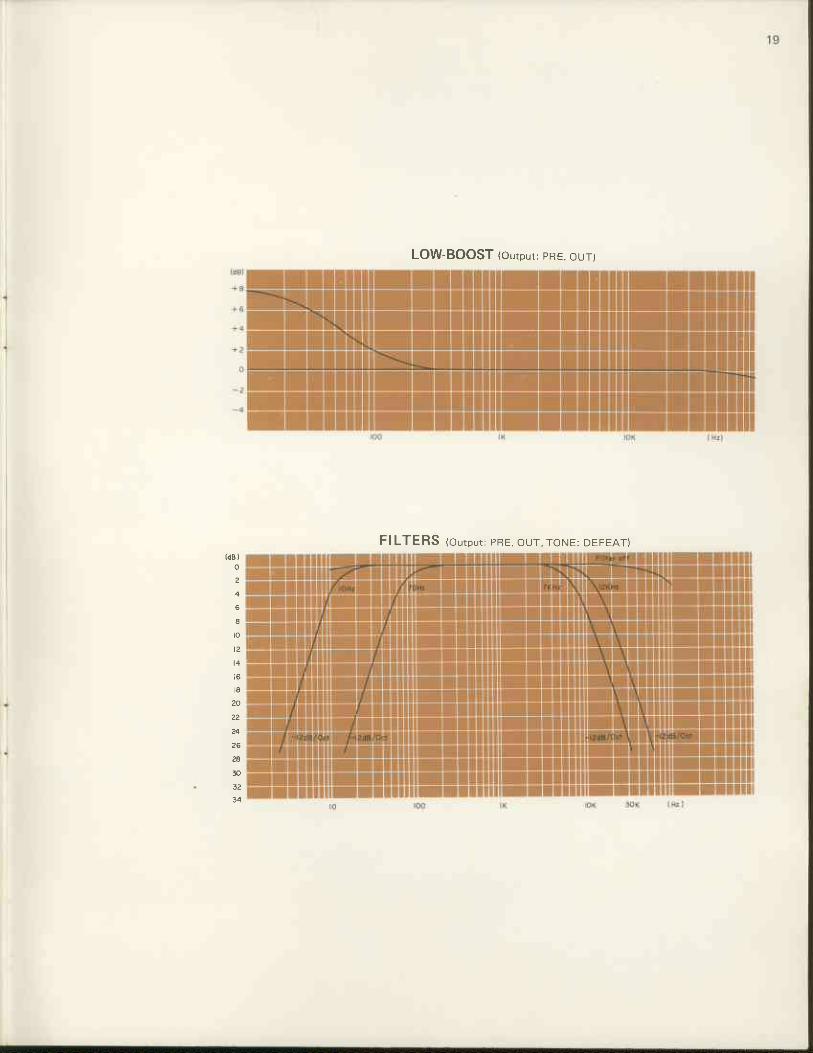
LOW-BOOST (output: pRE. our)
FILTERS (ou tpu t : pRE. oLJT. roNE: DEr-EAr )(dB l
2
a
t z
20
22
26
30

MAIN AMP: FREOUENCY RESPONSE r r i r , , r r L , , i r ! . i r . rL r r ' . , ! r
M A I N A M P : P O W E R v s . T O T A L H A R M O N I C D I S T O R T I O N 1 8 o l r n , < , ' d s )