OWNER'S MANUALd3is8fue1tbsks.cloudfront.net/PDF/Vestil/PEL-88 Lift.pdf · Read owner's manual...
19
1 Vestil Manufacturing Company 2999 North Wayne St., Angola, IN 46703 Ph 260-665-7586 • Fax: 260-665-1339 E-mail: [email protected] • www.vestil.com WARNINGS & SAFETY INSTRUCTIONS Read owner's manual completely before operating unit! • Never go under deck if there is load on unit. • Never operate unit unless you are watching it. • Stand clear from load when operating. • Do not operate unit unless all cover plates are securely in place. • Do not continue to press the up-button if deck is not raising. • Never exceed the maximum loading capacity model PEL-88A & PEL-88 .................................. 175 lbs. model PEL-100A & PEL-100 .............................. 125 lbs. model PEL-400-57 & PEL-400-72 ....................... 400 lbs. • Load must be evenly distributed on deck to ensure stability. • Consult factory for uneven loading. • Always operate unit on a level surface to ensure stability. • Always apply wheel brakes when unit is not being moved. • Use caution in moving a loaded unit; avoid obstructions and floor defects. • Remove load & disconnect power before working on unit. • Consult factory if adding or performing any modifications to the original equipment. • Use only maintenance parts supplied or approved by the manufacturer. • Make sure all operator safety labels are in place. ALUMINUM QUICK LIFTS MODEL PEL-88A & PEL-100A STEEL QUICK LIFT MODELS PEL-88, PEL-100, PEL-100-SWA & PEL-400 OWNER'S MANUAL Revised 03-15 A company dedicated to solving ergonomic and material handling problems since 1955. ALUMINUM & STEEL QUICK LIFTS Ergonomic Solutions CONTENTS Warning and Safety Instructions ............................ 1 Receiving Instructions ............................................ 1 Loading Instructions ............................................... 2 Operating Instructions ............................................ 2 Electrical Diagram .................................................. 3 Troubleshooting Guide ........................................... 4 Parts for PEL-88A & PEL-100A ............................. 5 Chain Tension Adjustment for PEL-88 .................... 7 Parts for PEL-88 & PEL-100 ................................ 8-9 Warning Labels for PEL-88 & PEL-100 ................ 12 Chain Tension Adjustment for PEL-400 ................ 13 Parts for PEL-400 ............................................14-15 Warning Labels for PEL-400 ................................. 16 Limited Warranty ................................................... 17 RECEIVING INSTRUCTIONS Every unit is thoroughly tested and inspected prior to shipment. However, it is possible that the unit may incur damage during transit. If you see damage when unloading make a note of it on the SHIPPER RECEIVER. Remove all packing and strapping material, inspect for damage. IF DAMAGE IS EVIDENT, FILE A CLAIM WITH THE CARRIER IMMEDIATELY! Also, check the unit size, type of power unit, etc., to ensure the unit is correct for the intended application. PEL-88A PEL-100A PEL-88 PEL-100 PEL-400-57 PEL-400-72 E S P A N O L E N G L I S H F R A N Ç A I S Warning Labels for PEL-88A & PEL-100A..............6 Parts Diagram & Breakdown PEL-100-SWA ... 10-11
Transcript of OWNER'S MANUALd3is8fue1tbsks.cloudfront.net/PDF/Vestil/PEL-88 Lift.pdf · Read owner's manual...

1
Vestil Manufacturing Company2999 North Wayne St., Angola, IN 46703Ph 260-665-7586 • Fax: 260-665-1339
E-mail: [email protected] • www.vestil.com
WARNINGS & SAFETY INSTRUCTIONSRead owner's manual completely before operating unit!• Never go under deck if there is load on unit.• Never operate unit unless you are watching it.• Stand clear from load when operating.• Do not operate unit unless all cover plates are securely
in place.• Do not continue to press the up-button if deck is not
raising.• Never exceed the maximum loading capacity
model PEL-88A & PEL-88 .................................. 175 lbs.model PEL-100A & PEL-100 .............................. 125 lbs.model PEL-400-57 & PEL-400-72 ....................... 400 lbs.
• Load must be evenly distributed on deck to ensurestability.
• Consult factory for uneven loading.• Always operate unit on a level surface to ensure stability.• Always apply wheel brakes when unit is not being
moved.• Use caution in moving a loaded unit; avoid obstructions
and floor defects.• Remove load & disconnect power before working on unit.• Consult factory if adding or performing any modifications
to the original equipment.• Use only maintenance parts supplied or approved by the
manufacturer.• Make sure all operator safety labels are in place.
ALUMINUM QUICK LIFTSMODEL PEL-88A & PEL-100ASTEEL QUICK LIFT MODELS PEL-88, PEL-100, PEL-100-SWA & PEL-400
OWNER'SMANUAL
Revised 03-15
A company dedicated to solving ergonomic and materialhandling problems since 1955.
ALUMINUM & STEELQUICK LIFTS
Ergonomic Solutions
CONTENTS
Warning and Safety Instructions ............................1
Receiving Instructions ............................................ 1
Loading Instructions ............................................... 2
Operating Instructions ............................................ 2
Electrical Diagram .................................................. 3
Troubleshooting Guide ........................................... 4
Parts for PEL-88A & PEL-100A .............................5
Chain Tension Adjustment for PEL-88 .................... 7
Parts for PEL-88 & PEL-100 ................................8-9
Warning Labels for PEL-88 & PEL-100 ................ 12Chain Tension Adjustment for PEL-400 ................ 13Parts for PEL-400 ............................................14-15Warning Labels for PEL-400 ................................. 16Limited Warranty ................................................... 17
RECEIVING INSTRUCTIONSEvery unit is thoroughly tested and inspected prior
to shipment. However, it is possible that the unit may incurdamage during transit. If you see damage when unloadingmake a note of it on the SHIPPER RECEIVER.Remove all packing and strapping material, inspect fordamage. IF DAMAGE IS EVIDENT, FILE A CLAIM WITHTHE CARRIER IMMEDIATELY! Also, check the unit size,type of power unit, etc., to ensure the unit is correct forthe intended application.
PEL-88APEL-100A
PEL-88PEL-100
PEL-400-57PEL-400-72
ESPANOL
ENGLISH
FRANÇAIS
Warning Labels for PEL-88A & PEL-100A..............6
Parts Diagram & Breakdown PEL-100-SWA ... 10-11

2
LOADING INSTRUCTIONSThe load capacity rating as inscribed on the
nameplate of your unit designates the net capacity, assumingthe load is centered on the deck. This capacity must neverbe exceeded, as permanent damage or injury may result.
OPERATING INSTRUCTIONSPosition of the deck is controlled by the raise/
lower buttons on the touchpad. Speed is controlled fromtouchpad. A hand-held pendent control is optional.
BATTERY RECHARGING & CAREThe battery is completely sealed and is,
therefore, maintenance-free and drip proof.
The on-board charger operates on 115VAC andrequires a 3-wire (grounded) extension cord. It monitorsand reacts to the battery voltage, turning on the greenLED on top of the charger when the batteries are fullycharged.A fully charged battery in good condition should read12.65 volts. Wait at least 1/2 hour after the charger hasbeen turned off before checking the battery voltage.
Charge the batteries for at least four hours priorto first use. The charge interval of this unit will vary basedon the load and frequency of use. Since the majority ofapplications require less than the maximum capacity andonly intermittent use the actual time between charging willonly be found through experience. Also, the batteriesshould be fully recharged each time. This will increasethe battery life.
• Charge unit at least once every two weeks.
• Leave plugged in when not in used. Disconnect batterywhen storing the unit without power for more than onemonth.
• The battery charger can be connected for extendedperiods without damage to the batteries.
• Do not expose the lift or charger to rain or adverseconditions.
BE SURE ALL POWER IS OFF BEFORE ATTEMPTINGTO WORK ON THIS EQUIPMENT!
CAUTION: SERVICE WORK SHOULD BE PERFORMED ONLY BYTRAINED & QUALIFIED PERSONNEL
RESPONSIBILITIES OF OWNERS/USERSIt is the responsibility of the owner/user for the following:1) The unit must be inspected and maintained in
accordance with the guidelines in this manual.
2) Any unit not in safe operating condition must beremoved from service until it is returned to properoperating condition. All repairs and maintenancemust be performed by qualified personnel.
3) Unit may only be used by authorized personnel.All operators must have read and understood alloperating procedures and safety guidelines in thisOwner's Manual.
4) Operator must ensure that all safety features ofthe unit are functioning properly before each use.
PERIODIC MAINTENANCE INSTRUCTIONS
Before Each Use Check For The Following:1) Structural deformation of frame.2) Proper operation of casters.3) Unusual noise or binding.4) Signs of wear, fatigue or loosening of any moving
parts and contact areas.5) Check chain tension and adjust if applicable
(see chain tension adjustment section).
WARNING!Over tensioning of the chain can
cause potential damage and/or injury.
6) Wear on the chain roller bushings.7) Cover plates being securely in place.
DO NOT use if there are any of the above!
Monthly Inspections1) Check for frayed or loose wires.2) Clean off dirt and debris at all contact areas.3) Make sure all warning and safety labels are in
place and in good condition.4) Battery Condition
Ordering Replacement or Extra PartsOur company takes pride in using the finest
available parts for our equipment. We are not responsiblefor equipment failure resulting from the use of unapprovedreplacement parts. To order replacement or extra parts foryour equipment contact Customer Service at the factory. Inany correspondence with the factory please include theSerial Number which is inscribed on the nameplate of thepiece of equipment. Use only the part numbers provided inthis Owner's Manual.
3
ELECTRICAL DIAGRAMFOR ALUMINUM & STEEL QUICKLIFTS
ENGLISH

4
TROUBLESHOOTING QUICK REFERENCE GUIDEFOR STEEL QUICKLIFTS
Observation Possible Cause Remedy1.) Power unit does not run when control
is operated.
2.) Motor hums, platform would not move.
3.) Unit turns off before reaching the fullyraised or lowered height.
4.) Over/under temp cutback.(LED flashes • •)
5.) Pot high or low signal out of range.(LED flashes • •• or ••• • or ••• •••••)
6.) Speed limit pot fault.(LED flashes • •••)
7.) Precharge Fault (LED ••• •••)
8.) Current sense voltage fault(LED •••• ••)
9) Motor Clicks
a. Battery voltage low. (< 17)(LED flashes • ••••)
b. Bad wiring connection / brokenwire in circuit.
c. Hand control's plug loose in thetouchpad socket.
d. Problem with moror/control (check forLED flashes code on the touchpad).
e. Unit is plugged into a 115V circuit.
f. CB or Fuse Blown
a. Battery voltage low.
b. Platform overloaded.
*c. Chain/Master link broken.
d. Obstruction/jammed chain.
a. Battery voltage low.
b. Platform roller bearing obstructed or isbinding.
c. The "platform raised" limit switch isengaged too soon, or is bad(PEL-400 only).
d. Platform overloaded.
a. Temperature > 92°C or < -25°C.
a. Throttle input wire open or shorted.b. Throttle pot defective.
a. Speed limit pot wire(s) broken or shorted.b. Broken speed limit potentiometer.
a. Controller failure; low battery voltage.
a. Short in motor or in motor wiring.b. Controller failure.
a. Overloaded deck.
a. Charge battery.
b. Visually inspect wires, do continuitychecks with meter. Refer to electricaldiagram.
c. Push plug in place.
d. Consult diagnostics page.
e. Unplug cord.
f. Reset CB. Replace fuse.
a. Charge battery.
b. Check load; reduce if necessary.
c. Inspect chain, rollers, roller track, andpulley assembly.
d. Clear Obstruction.
a. Charge battery.
b. Inspect roller track for interferenceor damage.
c. Adjust the limit switch pulley spring'stension; test switch with meter.
d. Check load; reduce if necessary.
a. Check load; reduce if necessary.
a. Verify wiring not damaged.b. Consult factory.
a. Verify wiring if not damaged.b. Consult factory.
a. Charge battery.
a. Verify motor wiring.b. Consult factory.
BE SURE ALL POWER IS OFF AND ALWAYS UNLOAD LIFT BEFORE ATTEMPTING TOWORK ON THIS EQUIPMENT!
CAUTION: SERVICE WORK SHOULD BE PERFORMED ONLY BY TRAINED & QUALIFIED PERSONNEL
NOTE: TOUCHPAD IS NOT SERVICEABLE.DO NOT OPEN TOUCHPAD OR WARRANTY WILL BE VOID!!!

Delrin 1.36in. x 0.375in. aluminum roller assembly 42-527-001
6
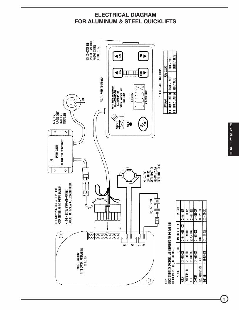
WARNING LABEL IDENTIFICATIONFor Aluminum Quick Lift • Model PEL-88A & PEL-100A
MAKE SURE ALL WARNING LABELS ARE IN PLACE!
1
2
*Product safety signs or labels should beperiodically inspected and cleaned by theproduct users as necessary to maintaingood legibility for safe viewing distance ...ANSI 535.4 (10.21)Contact manufacturer for replacementlabels.
ALUMINUM QUICKLIFTMODEL PEL-88A & PEL-100A
Charge unit at least every two weeks or leave plugged in when not in use.Disconnect battery when storing unit without power for more than one month.
454VESTIL MANUFACTURING CORP. • Angola, IN 46703 USAPhone (260) 665-7586 • Fax (260) 665-1339 • www.vestil.com
Cargue la unidad por lo menos cada dos semanas o enchupelo cuando no en
uso. Desconecte la batería al salvar la unidad sin carga por más de un mes.
Charger l'unité au moins deux fois par semaine ou laiser branché lorsque labatterie lorsque l'unité est rangée et ne va pas fonctionner pendant plus d'unmois.
PEL BATTERY CONNECTIONS
The red wire (from T1 on the motor controller) connectsto one side of the circuit breaker. The other side of thecircuit breaker connects to the positive (+) post (red) onBAT1.
The short jumper wire connects between the BAT1negative (-) post (black) and BAT2 positive (+) post (red).
The unfused black wire (from T2 on the controller)connects to the negative (-) post (black) on BAT2.
The charger plugs into the quick-connect harness locatedon the end of the touchpad harness.
CONEXIONES DE LA BATERIA PEL
El alambre rojo (del T1 en el control del motor) se conectaa un lado del corto circuito. El otro lado del corto circuitose conecta al poste (rojo) positivo (+) en BAT1.
El alambre de salto corto se conecta entre el poste (negro)BAT1 negativo (-) y el poste (rojo) BAT2 positivo (+).
El alambre negro sin fusible (del T2 en el control) seconecta al poste (negro) negativo (-) en el BAT2.
El cargador se enchufa en el equipo de conexión rápidalocalizado en el extremo del equipo del telclado.
CONNEXIONS DE BATTERIE PEL
Le fil rouge (de T1 sur le contrôleur du moteur) connecteà un côté du disjoncteur. L’autre côté du disjoncteurconnecte à l’anode (borne positive) - rouge - de BAT1.
Le fil de liaison court connecte entre la cathode BAT1(négative) - noir - et l’anode BAT2 (positive) - rouge.
Le fil noir sans fusible (de T2 sur le régulateur de charge)connecte à la borne négative (noir) de BAT2.
Le chargeur de batterie branche à la distribution électriquede la prise de courant située sur le bout de la touche àeffleurement.
Charger12V
Charger
Curicut
Motor
BAT1 BAT2
CargadorBaterias
Corto
Localizacion
BAT1 BAT2
Cargador
ChargeurBatteries
Situa
1BAT 2BAT
La
Disjoncteur
399
3
4
1
Vertical on side
24
Inside
3
DO NOT LOAD beyond rated capacity
DISTRIBUTE LOAD EVENLY
SECURE AND LOWER load before moving
KEEP CLEAR when lowering
DO NOT sit or ride on cart
READ OWNERS MANUAL before using or working on thisequipment
SHUT POWER off before working on this equipment
NO CARGUE más allá de la capacidad tasada
DISTRIBUYA LA CARGA UNIFORMEMENTE
ASEGURE Y DESCIENDA la carga antes de mover
MANTENGASE ALEJADO cuando descienda
NO SE SIENTE o vaya en el carro
LEA EL MANUAL DEL PROPIETARIO antes de usar o trabajaren este equipo
Apage el equipo antes de trabajar en èl
NE PAS CHARGER au-delà de capacité
DISTRIBUER la charge régulièrement
BIEN FIXER ET FAIRE DESCENDRE la charge avant de faire un mouvement
VOUS DEGAGER quand la charge descend
NE PAS VOUS ASSEOIR OU VOUS PROMENER sur le chariot
LIRE LE GUIDE avant d’utiliser ou de travailler sur cet équipment
COUPER L’ALIMENTATION avant de faire des travaux sur cet équipement
WARNING! ADVERTENCIA! AVERTISSEMENT!
589
KEEP CLEARWHEN IN USE
MANTENGASEALEJADO CUANDO SE
ESTA OPERANDO
SE TENIR ÀDISTANCE LORS DUFONCTIONNEMENT
ADVERTENCIAWARNING AVERTISSEMENT!! !
220

7
INSTRUCTIONS FOR ADJUSTING THE LIFTING CHAINS TENSIONFOR STEEL QUICKLIFT • MODEL PEL-88
READ ALL INSTRUCTIONS BEFORE PROCEEDING!Only trained and qualified service personnel should work on this equipment!
Lock out all potential energy sources before attempting this installation!
1) Remove any load that is on the machine and run the platform up until it is raised halfway up the mast.2) Above the platform, locate the tensioning bolts (item 1; one at each end of the chain). Loosen the two jamb
nuts (item 2) by turning them in a counterclockwise direction. (Use a 7/16" wrench on the nut, and another7/16" wrench to keep the chain from turning.) Loosen each until it is at the end of its respective chain tensionbolt.
3) Run the platform all the way up to the top of the mast until it stops moving.4) Again using the 7/16" wrenches, turn the tensioning nuts (item 3) at each end of the chain until you can pull
the chain 3" away from the front of the mast at its midheight. Be sure to turn each nut about the same amount.5) Lower the platform to the bottom of the mast, holding the "Lower" pushbutton for two seconds after the
platform hits bottom. If the chain "jumps" ont he sprocket, raise the platform up again. Tighten one of thetensioning nuts another 1/2 turn (clockwise) and repeat the test.
6) Raise the platform back up halfway to the top of the mast and turn each of the jamb nuts until they are againstthe tensioning nuts; then tighten each one wrench-tight.
CAUTIONS:• Double-check that both of the holding nuts have been adequately tightened down before placing the machine
back into service.
NOTES:• The chain's tension, the tension bolts, and the adjustment nuts should all be checked monthly.
1
3
2
PLATFORMCARRIAGESIDE VIEW
STEEL QUICKLIFTMODEL PEL-88 & PEL-100
ENGLISH

8
PARTS DRAWING FOR STEEL QUICK LIFTMODEL PEL-88 & PEL-100
1
2
46
816
153
4A, 4B
5
6A, 6B
78
10
11
38
1219
20
8
15 1617
14
22
30
27
292827
26
1821
25
40
STEEL QUICKLIFTMODEL PEL-88 & PEL-100
39
24

9
ITEM NO.123
4A4B5
6A6B78
101112*1314151617181920212224252627282930*31*35*37383940*42*44*4546*47*48*49*50*51
DESCRIPTIONDeck 24"W x 19"LScrew & nylock nut,Roller w/nylock nut, 5/16"-18UNCChain, no.35 x 127" lg (PEL-88)Chain no. 35 x 157" lg (PEL-100)Chain Connecting Link 41-1/2" pitch - 1/4 widthFront Cover (left side)Front cover (right side)Screw, 1/4"-20UNC x 3/4" (Type F, HWH)Nylock nut, 3/8"-16UNCCaster w/o brakePlastic capCaster w/Brake (3 x 1-1/2)Screw, 3/8-16 unc x 5/8 (FHSCS)Pulley bracketChain Roller (plastic)Roller BearingBolt 3/8-16 unc x 1-3/4" (HHCS)Motor (Leeson)Bolt & Nylock Nut 1/4-20 unc x 1-1/4Back CoverSprocket 5/8" bore w/keyway & set screwBatteryBattery ChargerBolt & Nylock Nut & Washer - 1/8-27 unc x 4 (HHCS)Spring Rod Bolt 1/2-13 unc x 8Spring Rod Nut 1/2-13 uncWasher 1/2 x 1-1/2 Fender Washer 2 platedSpringHandle GripHand Control w/Coil Cord (optional)Bolt 3/8-16 unc x 2-1/4 (HHCS)Circuit BreakerMotor ControllerTouchpadPower Inlet, 115V w/ 1-1/2" NutBolt Control Mt. 8-32 unc x 1Bolts, Chain Adjusting 1/4-20 x 2 eyeboltNuts, Chain Adjusting Bolt 1/4-20Chain CoverChain Cover Retaining Bolts (400 series only)Bolt (400 series only)Nut 8-32 uncWasher (400 series only)Nuts, Motor Controller 8-32 unc
QTY1-411111--222-144-1-1121----121-111----1
ENGINEER NO.21-013-057n/a20-110-00821-042-01221-042-01321-042-01421-024-01321-024-014n/an/a16-132-07021-024-01616-132-071n/a21-016-05021-042-02021-113-027n/a21-641-001n/a21-024-01221-042-01521-139-00121-034-002n/an/an/an/a21-146-00415-025-00699-522-001n/a21-034-00621-156-00421-156-00221-034-005n/an/an/a21-524-001
n/a
n/a
* Not Shown in Diagram
PARTS IDENTIFICATION FOR STEEL QUICK LIFTMODEL PEL-88 & PEL-100
PART NO.PEL-DCKn/aPEL-RNYKNTPEL-CHN127PEL-CHN157PEL-CCPEL-FCLSPEL-FCRSn/an/aPEL-CSTRPEL-PCPEL-CSTBRKn/aPEL-PLYBRKPEL-CHRLRPEL-RLRBRn/aPEL-MTRn/aPEL-BCPEL-SKT5/8PEL-BATTPEL-BATTCHRn/an/an/an/aPEL-SPGPEL-HGPEL-CNTLn/a
PEL-MTRCNTLPEL-TCHPDPEL4-PINLTn/an/an/aPEL-CHNCVR
n/a
n/a
STEEL QUICKLIFTMODEL PEL-88 & PEL-100
ENGLISH

PEL-100-SWA EXPLODED PARTS DIAGRAM AND BILL OF MATERIALS
STEEL QUICKLIFT MODELS PEL-88 & PEL-100
10
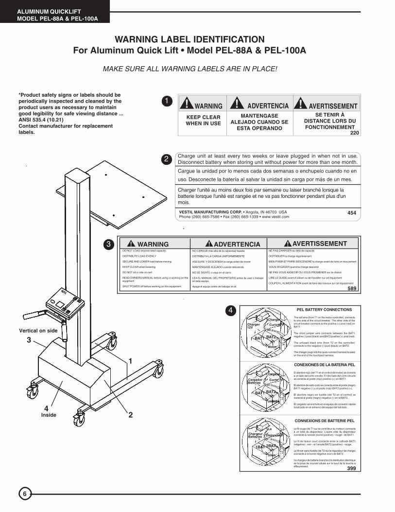
PEL-100-SWA BILL OF MATERIALS
STEEL QUICKLIFT MODELS PEL-88 & PEL-100
11
Item no. Part no. Description Quantity 1 42-514-003 Weldment, frame 1 2 42-538-001 Weldment, carriage 1 3 20-110-008 Roller bearing 4 4 11003 1/4 in. – 20 UNC x 3/4 in. bolt 4 5 11105 3/8 in. – 16 UNC x 1 in. bolt 4 6 37024 3/8 in. lock nut 6 7 21-135-001 Motor 1 8 21-156-002 Electronic touchpad controller 1 9 21-034-010 24V battery charger 1
10 21-139-001 12 VDC battery 2 11 21-034-025 Flanged electrical inlet sleeve with locking ring 1 12 11012 1/4 in. – 20 x 21/4 in. HHCS #2 zinc-plated bolt 4 13 33004 1/4 in. type A narrow flat washer 2 14 33008 3/8 in. USS zinc-plated flat washer 20 15 16-132-155 HR-4/1.25-SLB-S swivel-type polyurethane stem
caster 2
16 16-132-156 HR-4/1.25-SLB-S swivel-type polyurethane stem caster
2
17 11109 3/8 in. – 16 UNC x 11/2 in. HHCS #2 zinc-plated bolt 4 18 16-132-009 PP-4/1.25-W polyurethane wheel 4 19 11119 3/8 in. – 16 UNC x 4 in. HHCS bolt 2 20 37018 1/4 in. – 20 UNC zinc-plated lock nut 2 21 37030 1/2 in. – 13 lock nut 4 22 20-538-002 Stretch wrap carriage assembly 1 23 20-016-076 Roller bracket 2 24 20-525-001 Handle weldment 1 25 33011 1/2 in. USS plain flat washer 4 26 21-156-006 Electrical control box 1 27 21-024-042 Motor cover 1

12
WARNING LABEL IDENTIFICATIONFor Steel Quick Lift • Model PEL-88 & PEL-100
MAKE SURE ALL WARNING LABELS ARE IN PLACE!
*Product safety signs or labels should be periodicallyinspected and cleaned by the product users as necessaryto maintain good legibility for safe viewing distance ...ANSI 535.4 (10.21)Contact manufacturer for replacement labels.
STEEL QUICKLIFTMODEL PEL-88 & PEL-100
Charge unit at least every two weeks or leave plugged in when not in use.Disconnect battery when storing unit without power for more than one month.
454VESTIL MANUFACTURING CORP. • Angola, IN 46703 USAPhone (260) 665-7586 • Fax (260) 665-1339 • www.vestil.com
Cargue la unidad por lo menos cada dos semanas o enchupelo cuando no en
uso. Desconecte la batería al salvar la unidad sin carga por más de un mes.
Charger l'unité au moins deux fois par semaine ou laiser branché lorsque labatterie lorsque l'unité est rangée et ne va pas fonctionner pendant plus d'unmois.
PEL BATTERY CONNECTIONS
The red wire (from T1 on the motor controller) connectsto one side of the circuit breaker. The other side of thecircuit breaker connects to the positive (+) post (red) onBAT1.
The short jumper wire connects between the BAT1negative (-) post (black) and BAT2 positive (+) post (red).
The unfused black wire (from T2 on the controller)connects to the negative (-) post (black) on BAT2.
The charger plugs into the quick-connect harness locatedon the end of the touchpad harness.
CONEXIONES DE LA BATERIA PEL
El alambre rojo (del T1 en el control del motor) se conectaa un lado del corto circuito. El otro lado del corto circuitose conecta al poste (rojo) positivo (+) en BAT1.
El alambre de salto corto se conecta entre el poste (negro)BAT1 negativo (-) y el poste (rojo) BAT2 positivo (+).
El alambre negro sin fusible (del T2 en el control) seconecta al poste (negro) negativo (-) en el BAT2.
El cargador se enchufa en el equipo de conexión rápidalocalizado en el extremo del equipo del telclado.
CONNEXIONS DE BATTERIE PEL
Le fil rouge (de T1 sur le contrôleur du moteur) connecteà un côté du disjoncteur. L’autre côté du disjoncteurconnecte à l’anode (borne positive) - rouge - de BAT1.
Le fil de liaison court connecte entre la cathode BAT1(négative) - noir - et l’anode BAT2 (positive) - rouge.
Le fil noir sans fusible (de T2 sur le régulateur de charge)connecte à la borne négative (noir) de BAT2.
Le chargeur de batterie branche à la distribution électriquede la prise de courant située sur le bout de la touche àeffleurement.
VESTIL MANUFACTURING CORPORATIONAngola, Indiana USA
Phone (260) 665-7586 • www.vestil.com
Charger12V
Charger
Curicut
Motor
BAT1 BAT2
CargadorBaterias
Corto
Localizacion
BAT1 BAT2
Cargador
ChargeurBatteries
Situa
1BAT 2BAT
La
Disjoncteur
399Revision 1003
1
2
3
4
2
1
3
4Inside
DO NOT LOAD beyond rated capacity
DISTRIBUTE LOAD EVENLY
SECURE AND LOWER load before moving
KEEP CLEAR when lowering
DO NOT sit or ride on cart
READ OWNERS MANUAL before using or working on thisequipment
SHUT POWER off before working on this equipment
NO CARGUE más allá de la capacidad tasada
DISTRIBUYA LA CARGA UNIFORMEMENTE
ASEGURE Y DESCIENDA la carga antes de mover
MANTENGASE ALEJADO cuando descienda
NO SE SIENTE o vaya en el carro
LEA EL MANUAL DEL PROPIETARIO antes de usar o trabajaren este equipo
Apage el equipo antes de trabajar en èl
NE PAS CHARGER au-delà de capacité
DISTRIBUER la charge régulièrement
BIEN FIXER ET FAIRE DESCENDRE la charge avant de faire un mouvement
VOUS DEGAGER quand la charge descend
NE PAS VOUS ASSEOIR OU VOUS PROMENER sur le chariot
LIRE LE GUIDE avant d’utiliser ou de travailler sur cet équipment
COUPER L’ALIMENTATION avant de faire des travaux sur cet équipement
WARNING! ADVERTENCIA! AVERTISSEMENT!
VESTIL MANUFACTURING CORPORATION • Angola, Indiana USA • Phone (260) 665-7586 • Fax (260) 665-1339 • [email protected] • www.vestil.com589
KEEP CLEAR
WHEN IN USE
MANTENGASEALEJADO CUANDO SE
ESTA OPERANDO
SE TENIR ÀDISTANCE LORS DUFONCTIONNEMENT
ADVERTENCIAWARNING AVERTISSEMENT!! !
13
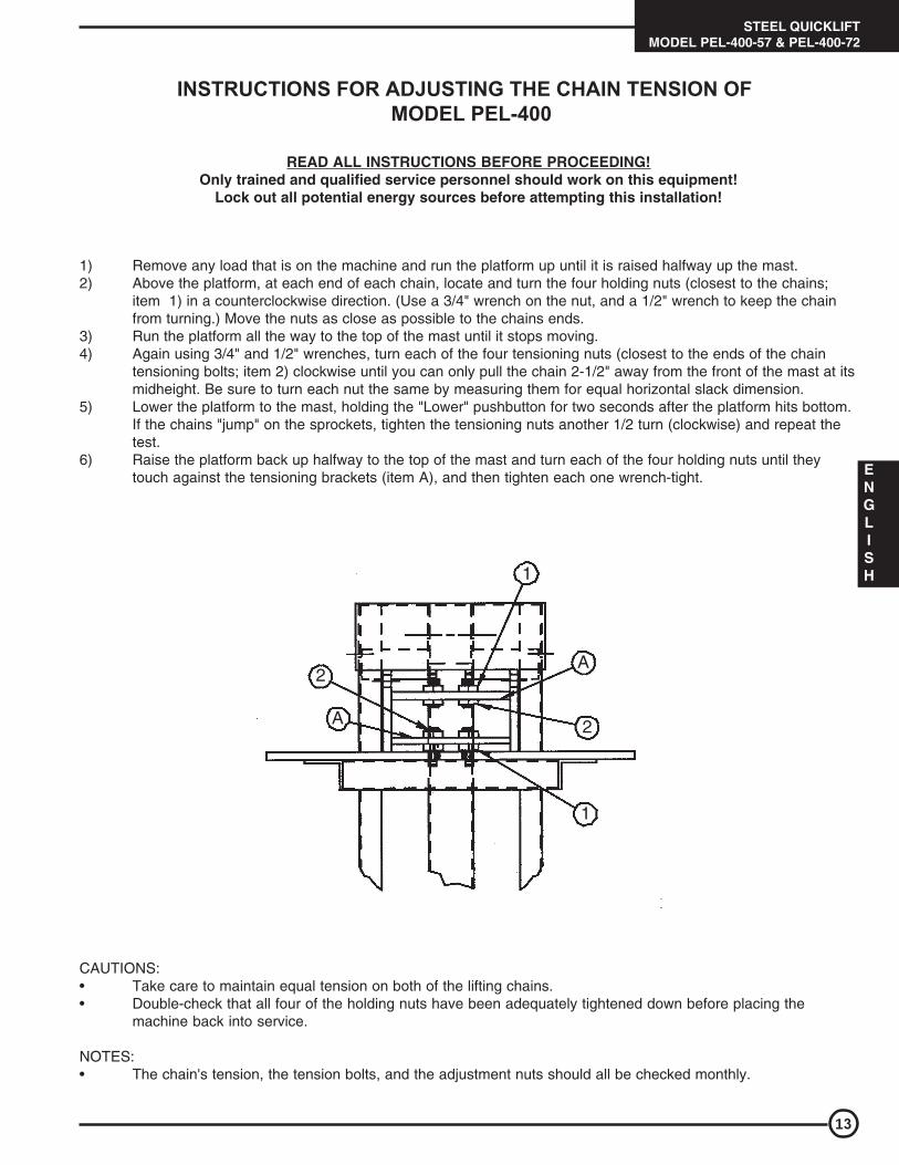
INSTRUCTIONS FOR ADJUSTING THE CHAIN TENSION OF MODEL PEL-400
READ ALL INSTRUCTIONS BEFORE PROCEEDING!Only trained and qualified service personnel should work on this equipment!
Lock out all potential energy sources before attempting this installation!
1) Remove any load that is on the machine and run the platform up until it is raised halfway up the mast.2) Above the platform, at each end of each chain, locate and turn the four holding nuts (closest to the chains;
item 1) in a counterclockwise direction. (Use a 3/4" wrench on the nut, and a 1/2" wrench to keep the chainfrom turning.) Move the nuts as close as possible to the chains ends.
3) Run the platform all the way to the top of the mast until it stops moving.4) Again using 3/4" and 1/2" wrenches, turn each of the four tensioning nuts (closest to the ends of the chain
tensioning bolts; item 2) clockwise until you can only pull the chain 2-1/2" away from the front of the mast at itsmidheight. Be sure to turn each nut the same by measuring them for equal horizontal slack dimension.
5) Lower the platform to the mast, holding the "Lower" pushbutton for two seconds after the platform hits bottom.If the chains "jump" on the sprockets, tighten the tensioning nuts another 1/2 turn (clockwise) and repeat thetest.
6) Raise the platform back up halfway to the top of the mast and turn each of the four holding nuts until theytouch against the tensioning brackets (item A), and then tighten each one wrench-tight.
1
A
2
1
A
2
CAUTIONS:• Take care to maintain equal tension on both of the lifting chains.• Double-check that all four of the holding nuts have been adequately tightened down before placing the
machine back into service.
NOTES:• The chain's tension, the tension bolts, and the adjustment nuts should all be checked monthly.
STEEL QUICKLIFTMODEL PEL-400-57 & PEL-400-72
ENGLISH

PEL‐400‐57 Exploded Parts Diagram [NOTES: Bill of materials appears on following page; item no. 26 not shown]
14A
Closeup of idler sprockets:
Idler sprocketsPart no. 21‐042‐018

PEL‐400‐57 Bill of Materials:
Item no. Part no. Description Quantity
1 21‐513‐036 Assembly, deck 1
2 21‐024‐029 Guard, finished, top 1
3 15‐025‐006 Grip, handle 2
4 36209 1/2in. – 13 hex jam nut plain 8
5 11055 5/16in. – 18 x 1in. HHCS #2 zinc‐plated bolt 2
6 37021 5/16in. – 18 nylon lock nut, zinc‐plated, #2 2
7 15‐016‐068 Bracket, battery charger mount 1
8 33004 1/4in. flat washer type A narrow 4
9 11003 1/4in. – 20 UNC x 3/4in. bolt 4
10 37018 1/4in. – 20 UNC nylock nut zinc‐plated 3
11 21‐034‐010 Accessory, electric, battery charger, 24V 1
12 21‐156‐004 Control, motor, electronic, 1228 1
13 27402 RHSMS #8‐32 x 1in. 2
14 37012 #8‐32 nylock nut zinc‐plated 2
15 01‐022‐001 Limit switch with roller arm 1
16 22804 Elevator bolt, limit switch 1
17 21‐156‐002 Control, touchpad, electronic 1
18 21‐034‐025 Flanged inlet sleeve with locking ring 1
19 11107 3/8in. – 16 x 11/4in. HHCS #2 zinc‐plated bolt 4
20 37024 3/8in. nylock insert nut 4
21 21‐024‐038 Handle, grip, rubber end cap 2
22 33618 1/4in. lock washer 2
23 21‐002‐059 Frame assembly without power 1
24 21‐641‐002 Leeson motor/gearbox 1
25 21‐034‐004 Circuit breaker 1
26 21‐042‐017 #40 chain, 265 link 2
27 21‐145‐004 Specialty hardware, chain adjuster 4
28 21‐042‐019 Gearbox sprocket 1
29 99‐034‐013 Strap, battery box with buckle 1
30 21‐139‐002 Battery, 12VDC 2
14B
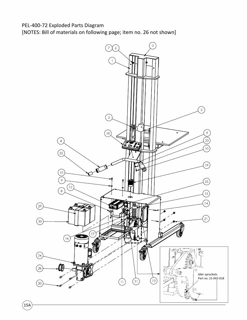
PEL‐400‐72 Exploded Parts Diagram [NOTES: Bill of materials on following page; item no. 26 not shown]
15A
Idler sprocketsPart no. 21‐042‐018

PEL‐400‐72 Bill of Materials:
Item no. Part no. Description Quantity
1 21‐002‐060 Frame assembly without power 1
2 21‐513‐036 Assembly, deck 1
3 21‐024‐029 Guard, finished, top 1
4 15‐025‐006 Grip, handle 2
5 36209 1/2in. – 13 hex jam nut plain 8
6 11055 5/16in. – 18 x 1in. HHCS #2 zinc‐plated bolt 2
7 37021 5/16in. – 18 nylon lock nut zinc‐plated, #2 2
8 15‐016‐068 Bracket, battery charger mount 1
9 33004 1/4in. flat washer type A narrow 4
10 11003 1/4in. – 20 UNC x 3/4in. bolt 4
11 37018 1/4in. – 20 UNC nylock nut, zinc‐plated 3
12 21‐034‐010 Accessory, electric, battery charger, 24V 1
13 21‐156‐004 Control, motor, electronic, 1228 1
14 27402 RHSMS #8‐32 x 1in. 2
15 37012 #8‐32 nylock nut zinc‐plated 2
16 01‐022‐001 Limit switch with roller arm 1
17 22804 Elevator bolt, limit switch 1
18 21‐156‐002 Control, touchpad, electronic 1
19 21‐034‐025 Flanged inlet sleeve with locking ring 1
20 11107 3/8in. – 16 x 11/4in. HHCS #2 zinc‐plated bolt 4
21 37024 3/8in. nylock nut 4
22 21‐024‐038 Handle, grip, rubber end cap 2
23 33618 1/4in. lock washer 2
24 21‐641‐002 Leeson motor/gearbox 1
25 21‐034‐004 Circuit breaker 1
26 21‐042‐021 #40 chain, 325 links 2
27 21‐145‐004 Specialty hardware, chain adjuster 4
28 21‐042‐019 Gearbox sprocket 1
29 99‐034‐013 Strap, battery box with buckle 1
30 21‐139‐002 Battery, 12VDC 2
15B

Label placement diagram:Each PEL‐400 should be labeled as shown in the diagram below. Contact the factory to order replacement labels.
Label 527: Only trained, authorizedpersons should operate this device
Label 212: Lock casters
Label 208: Keep clear of pinch point
Label 399: Battery connections
Label 287: Model & capacity
16
Label 454: Charge unit frequently
LIMITED WARRANTY
Vestil Manufacturing Corporation (“Vestil”) warrants this product to be free of defects in material and workmanship during the warranty period. Our warranty obligation is to provide a replacement for a defective original part if the part is covered by the warranty, after we receive a proper request from the warrantee (you) for warranty service.
Who may request service? Only a warrantee may request service. You are a warrantee if you purchased the product from Vestil or from an authorized distributor AND Vestil has been fully paid.
What is an “original part”? An original part is a part used to make the product as shipped to the warrantee.
What is a “proper request”? A request for warranty service is proper if Vestil receives: 1) a photocopy of the Customer Invoice that displays the shipping date; AND 2) a written request for warranty service including your name and phone number. Send requests by any of the following methods:
Mail Fax Email Vestil Manufacturing Corporation (260) 665‐1339 [email protected] 2999 North Wayne Street, PO Box 507 Phone Angola, IN 46703 (260) 665‐7586
In the written request, list the parts believed to be defective and include the address where replacements should be delivered.
What is covered under the warranty? After Vestil receives your request for warranty service, an authorized representative will contact you to determine whether your claim is covered by the warranty. Before providing warranty service, Vestil may require you to send the entire product, or just the defective part or parts, to its facility in Angola, IN. The warranty covers defects in the following original dynamic components: motors, hydraulic pumps, electronic controllers, switches and cylinders. It also covers defects in original parts that wear under normal usage conditions (“wearing parts”), such as bearings, hoses, wheels, seals, brushes, and batteries.
The warranty period for original components is 1 year. For wearing parts, the warranty period is 90 days. The warranty period begins on the date when Vestil ships the product to the warrantee. If the product was purchased from an authorized distributor, the period begins when the distributor ships the product. Vestil may extend the warranty period for products
shipped from authorized distributors by up to 30 days to account for shipping time.
If a defective part is covered by the warranty, what will Vestil do to correct the problem? Vestil will provide an appropriate replacement for any covered part. An authorized representative of Vestil will contact you to discuss your claim.
What is not covered by the warranty? 1. Labor;2. Freight;3. Occurrence of any of the following, which automatically voids the warranty:
Product misuse;
Negligent operation or repair;
Corrosion or use in corrosive environments;
Inadequate or improper maintenance;
Damage sustained during shipping;
Collisions or other incidental contacts causing damage to the product;
Unauthorized modifications: DO NOT modify the product IN ANY WAY without first receiving written authorizationfrom Vestil. Modification(s) might make the product unsafe to use or might cause excessive and/or abnormal wear.
Do any other warranties apply to the product? Vestil Manufacturing Corp. makes no other express warranties. All implied warranties are disclaimed to the extent allowed by law. Any implied warranty not disclaimed is limited in scope to the terms of this Limited Warranty.
17
How long is the warranty period?