LUMBING DIAGRAMS FOR BUBBLE PRODUCTS
14
1 PLUMBING DIAGRAMS FOR BUBBLE PRODUCTS ISSUE 03-02-15 © Euroship Services (UK) Ltd., Trading as:- Bubble Products 07-07-01. ©
Transcript of LUMBING DIAGRAMS FOR BUBBLE PRODUCTS
1
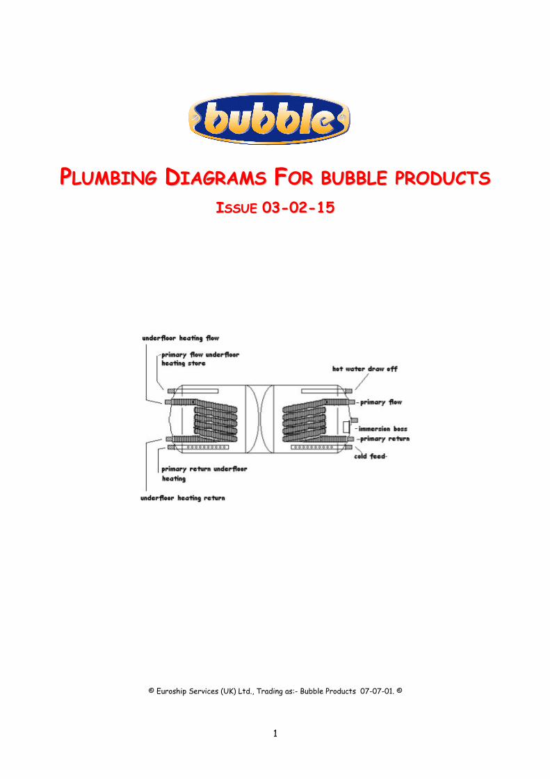
PPLLUUMMBBIINNGG DDIIAAGGRRAAMMSS FFOORR BBUUBBBBLLEE PPRROODDUUCCTTSS IISSSSUUEE 0033--0022--1155
© Euroship Services (UK) Ltd., Trading as:- Bubble Products 07-07-01. ©

2
Index
Introduction. ______________________________________________________________ 3
1. WARNINGS _____________________________________________________________ 3
2. Conventional Systems Oil Stove Fired. ________________________________________ 4
1. Unvented Oil Stove Gravity System ___________________________________________ 4
2. Oil Stove Pressurised System using two water circulating pumps. _____________________ 5
3. Conventional Systems Solid Fuel Fired. ________________________________________ 5
1. Gravity System. _________________________________________________________ 5
2. Solid Fuel Pumped system. _________________________________________________ 6
4. Oil Fired Bubble PJ Auto Boiler Systems. ______________________________________ 7
1. Schematic Grundfoss Twin Pump System. _______________________________________ 7
2. Schematic Y Plan System. __________________________________________________ 7
3. Schematic S Plan. ________________________________________________________ 8
4. Underfloor Heating using two thermal stores and Bubble PJ Auto Boiler. _______________ 8
5. Underfloor and conventional radiator plus hot water system. ________________________ 9
5. Two heat source systems. _________________________________________________ 10
1. Key to Diagram _________________________________________________________ 10
6. Solid fuel and auto boiler. _________________________________________________ 12
7. Notes and Commissioning Wet systems. _______________________________________ 12
1. CALORIFIERS. _________________________________________________________ 13
2. VENTING OF AIR. ______________________________________________________ 13
3. PIPE WORK. __________________________________________________________ 13
4. PUMPED SYSTEMS _____________________________________________________ 13
5. SAFETY VALVE ________________________________________________________ 13
6. WATER TREATMENT ___________________________________________________ 13
7. DRAIN DOWN. ________________________________________________________ 14
8. CIRCULATING PUMP. ___________________________________________________ 14
10. Associated Reading _____________________________________________________ 14

3
IINNTTRROODDUUCCTTIIOONN.. The following diagrams illustrate a variety of options which can be used in heating systems.
11.. WWAARRNNIINNGGSS 1. Where thermal stores, open vented cylinders and un-vented cylinders are illustrated, it is assumed that they
are designed and manufactured by approved manufacturers and are supplied complete with all safety devices
and interlocks which may not be illustrated in our diagrams.
2. Make sure that all equipment used such as pipe work, fittings, controls, wiring, electrical equipment, solar
equipment, cylinders, tanks, valves and thermal stores are all manufactured to the appropriate current national
standards.
3. Only suitably qualified persons are allowed to work on any systems or diagrams illustrated in this publication.
HETAS for solid fuel.
OFTEC for oil fired.
GAS SAFE registered engineers for gas.
Anyone working on unvented systems must have the appropriate qualifications.
4. Where solid fuel, non automatic stoves and boilers are illustrated, they must all have:-
An uninterrupted feed and expansion with no valving whatsoever between the appliance and the expansion tank,
minimum dia 28mm made from copper.
The feed and expansion must be correctly installed in line with manufactures instructions and all national rules
and regs currently in force.
F and E tanks and overflows must be made from metal.
ON SOLID FUEL SYSTEMS, where electrically operated valves are used, they must be normally open valve
which will fail open in the case of an electrical power cut.

4
22.. CCOONNVVEENNTTIIOONNAALL SSYYSSTTEEMMSS OOIILL SSTTOOVVEE FFIIRREEDD.. 11.. UUNNVVEENNTTEEDD OOIILL SSTTOOVVEE GGRRAAVVIITTYY SSYYSSTTEEMM

5
22.. OOIILL SSTTOOVVEE PPRREESSSSUURRIISSEEDD SSYYSSTTEEMM UUSSIINNGG TTWWOO WWAATTEERR CCIIRRCCUULLAATTIINNGG PPUUMMPPSS..
This is a system for use on vessels where two water circulating pumps are used.
The major problems with this type of design is that it is not prioritised and therefore the hot water and
heating tend to all be at the same temperature and take a much longer time to reach a useful working
temperature and the central heating can rob the hot water cylinder of its temperature.
33.. CCOONNVVEENNTTIIOONNAALL SSYYSSTTEEMMSS SSOOLLIIDD FFUUEELL FFIIRREEDD.. 11.. GGRRAAVVIITTYY SSYYSSTTEEMM..
It is important to make sure that the feed and expansion tank is located directly above the boiler.

6
22.. SSOOLLIIDD FFUUEELL PPUUMMPPEEDD SSYYSSTTEEMM..
It is important to make sure that the feed and expansion tank is located directly above the boiler.
The circulating pumps are controlled by a clip on pipe stat fitted to the hot water tank wired in such a way as
to allow the hot water pump to run first and the heating pump to run second.

7
44.. OOIILL FFIIRREEDD BBUUBBBBLLEE PPJJ AAUUTTOO BBOOIILLEERR SSYYSSTTEEMMSS.. 11.. SSCCHHEEMMAATTIICC GGRRUUNNDDFFOOSSSS TTWWIINN PPUUMMPP SSYYSSTTEEMM..
22.. SSCCHHEEMMAATTIICC YY PPLLAANN SSYYSSTTEEMM..

8
33.. SSCCHHEEMMAATTIICC SS PPLLAANN..
44.. UUNNDDEERRFFLLOOOORR HHEEAATTIINNGG UUSSIINNGG TTWWOO TTHHEERRMMAALL SSTTOORREESS AANNDD BBUUBBBBLLEE PPJJ AAUUTTOO BBOOIILLEERR..
This layout is designed to provide under floor heating and instant hot water using two small thermal stores.
The Bubble PJ Auto Boiler thermostat is set to run at 80 deg C and each of the thermal stores has its own
clip on, adjustable thermostat set at the temperature required for each application.
The hot water store is allowed to maintain a high temperature and the hot water outlet from the cylinder is
connected to a flow share blending valve which can be set at whatever temperature the user requires.
The underfloor heating store thermostat will control the temperature at whatever the user requires without
the need for complex manifolds and thermostats.
For the main part the system operates with a minimum of complexity and has a high degree of robustness and
longevity with water flow direction being mainly controlled by pumps as opposed to motorised valves.

9
55.. UUNNDDEERRFFLLOOOORR AANNDD CCOONNVVEENNTTIIOONNAALL RRAADDIIAATTOORR PPLLUUSS HHOOTT WWAATTEERR SSYYSSTTEEMM..
General description of circuit.
1. This circuit consists of a Marine type 230VAC, un-vented, automatic oil boiler, running on red diesel and
powering a mixture of under floor and conventional heating, plus hot water via an un-vented calorifyer.
Note that the hot water can be stored at a high temperature and at the hot water outlet a flow share vale can be fitted to regulate the water temperature.
2. The whole circuit is powered by 230VAC and standard domestic equipment is utilised.
3. The controls can be either Y plan or S plan or Pump plan.
To reduce electrical consumption the circulating pumps can be low wattage, “A” rated
Controls.
The whole system is automatically controlled allowing the user to set:-
1. The required on off times via the conventional 7 day programmer
2. The required room temperature via the room stat.
3. The required hot water stat via the cylinder stat.
4. The boiler operating temperature via the boiler stat.
5. The temperature of the underfloor heating pipework is controlled by item 4B which is a non electric,
thermostatically operated, three port valve with adjustable temperature settings from 20 to 60 degrees C.
10
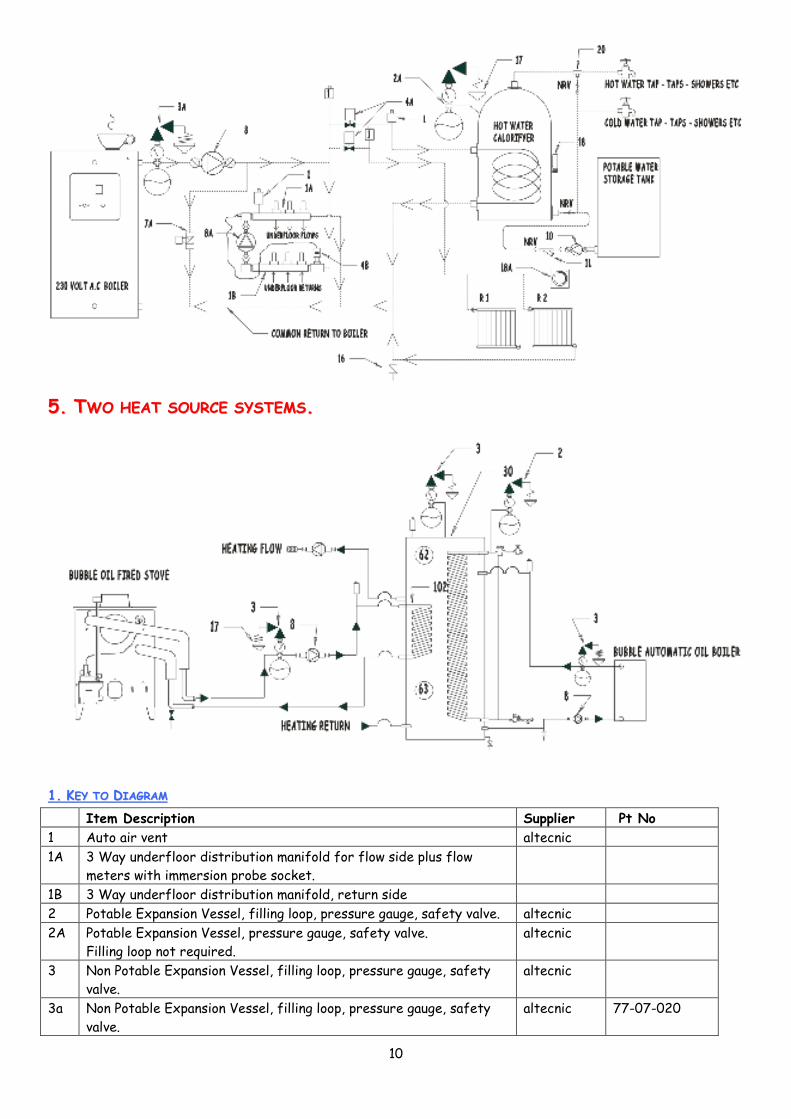
55.. TTWWOO HHEEAATT SSOOUURRCCEE SSYYSSTTEEMMSS..
11.. KKEEYY TTOO DDIIAAGGRRAAMM
Item Description Supplier Pt No
1 Auto air vent altecnic
1A 3 Way underfloor distribution manifold for flow side plus flow
meters with immersion probe socket.
1B 3 Way underfloor distribution manifold, return side
2 Potable Expansion Vessel, filling loop, pressure gauge, safety valve. altecnic
2A Potable Expansion Vessel, pressure gauge, safety valve.
Filling loop not required.
altecnic
3 Non Potable Expansion Vessel, filling loop, pressure gauge, safety
valve.
altecnic
3a Non Potable Expansion Vessel, filling loop, pressure gauge, safety
valve.
altecnic 77-07-020

11
4 3 Way motor valve danfoss
4A 2 Way motor valve danfoss
4B 3 Way non electric valve with thermostatic head and remote sensor.
5 Non Return valve.
7 61 deg flow share valve, three way. acasso
7A Differential bypass vale, adjustable, min 22mm
8 Circulating Pump and valve set.
8A Low wattage circulating pump and valve set. Laing
9 Automatic Filling valve ( High flow type.) normally open, only closed
for filter inspection, must be fitted on min dia 15mm feed pipe
within 1 meter of boiler.
9A Pressure regulation valve.
10 Pressure regulated, potable water pressurization pump.
11 Strainer.
12 Non return valve Min size 22mm.
14 High pressure fed, unrestricted mains cold water blow down valve,
Callefi 544 series.
Callefi B60012922
15 Sensor probe for Callefi blow down valve. To be inserted into boiler
sensing pocket.
INCLUDED INB60012922
16 Heat leak radiator of 2KW to be connected in the bypass circuit on
min dia 22mm pipe work. (28mm preferred)
17 Discharges from safety valves must go via visible tundishes to drain
capable of safely taking and discharging of high volume, boiling
water.
18 Clip on cylinder stat. danfoss
18A Room Thermostat
20 Blending Valve. altecnic
25 Normally open single port valve 28mm min or bigger depending upon
the boiler output.
30 Unvented Thermal Store sized to the situation requirements.
31 Open Vented Thermal Store, sized to the situation requirements.
40 Unvented Oil or Gas boiler, not combi
41 Open vented Oil or Gas boiler, not combi.
44 Wood Burning stove or boiler must be thermostatically controlled.
50 H20 or Compact wood pellet boiler. thermorossi
60 Emersion Heater
62 High limit thermostat
63 Low limit thermostat
101 Heat exchange coil for under floor heating sized to the heat load
102 Heat exchange coil for solar pick up sized to the solar panels.
103 Heat exchange coil for the automatic wood pellet boiler sized to
the boiler output.
104 Heat exchange coil for the domestic / commercial hot water
requirement in liter per minute of flow.
110 Solar Pumping and control station sized to match the solar panels. Acasso

12
66.. SSPPAACCEE HHEEAATTIINNGG SSOOLLIIDD FFUUEELL AANNDD BBUUBBBBLLEE PPJJ AAUUTTOO BBOOIILLEERR..
This is a typical layout of a broad beam narrowboat where a solid fuel corner stove and a PJ Auto Boiler are
used. Option 1 is where the boiler and hot water cylinder are fitted in the engine room using a horizontal
cylinder fitted on the swim top.
Option 2 is where the boiler is fitted in an aft galley and the hot water cylinder fitted in the bath room.
77.. NNOOTTEESS AANNDD CCOOMMMMIISSSSIIOONNIINNGG WWEETT SSYYSSTTEEMMSS..
PREAMBLE.
Installation of the wet appliances will be the same as for dry appliances except that when dealing with the
location an extra element comes in to the equation and that is connecting the stove up to the heating circuit.
Before designing the fireplace, take great care about making adequate provision for boiler connections.
To facilitate removal of the appliance, make sure that there is:-
• Easy access to the boiler unions.
• Easy access to the drain down valve.
• Easy access to any other connections.
When installing water heating Bubble stoves, the space heating output will be reduced slightly.
Bubble Boilers are generally high water content and suitable for pumped or gravity systems, provided that
the pipework is correctly designed.
If you are not suitably qualified, arrange for a heating engineer to do the design work for you.

13
11.. CCAALLOORRIIFFIIEERRSS..
Indirect calorifiers must be used on gravity or pumped systems.
On gravity systems the calorifiers must be located higher than the stove and as close as possible to it,
obviously keeping horizontal runs as short as possible, in some cases where this is not possible, it may be
necessary to fit a pump, just for the calorifyer.
22.. VVEENNTTIINNGG OOFF AAIIRR..
Gravity or Pumped systems must be open vented with cold feed, ball valve controlled expansion tanks.
The feed and expansion tank must be as close as possible to the boiler and be fitted at the highest part of
the circuit.
Consult an experienced boat-heating engineer for advice on feed and expansion tanks.
To vent the system of air use automatic air vents on all possible air lock locations.
33.. PPIIPPEE WWOORRKK..
All gravity pipe work must rise on flow and fall on return and be a minimum of 28mm dia. (35mm dia
preferred)
To reduce resistance to flow-:
• Use swept bends, do not use elbows.
• Use copper pipe work.
• Use high water content radiators.
3. On Bubble Stoves, the primary circuit must have a total length of not more than 6 meters otherwise the
recovery time of the calorifyer will be increased beyond an acceptable period of time. On PJ boilers this does
not apply.
4. Primary circuit pipe work must not have valves or other devices that can be used to interfere with the free
flow of water.
44.. PPUUMMPPEEDD SSYYSSTTEEMMSS
Always come off the stove with 28mm copper for a minimum run of 350 mm before dropping on to a
proprietary plastic heating pipe.
3. Great care should be taken with the positioning of the circulating pump/pumps and the feed and expansion
tank to make sure that the water flows where it should and that over pumping does not occur.
4. The heating circuit must be piped in 22mm copper or Hep 2o with 15mm stabs to radiators.
5. Where additional radiators are fitted as heat leaks, the pipe work must be kept as short as possible, rise
on feed and fall on return.
55.. SSAAFFEETTYY VVAALLVVEE
1. A 1" safety valve must be fitted as close to the boiler as possible (within 300mm) and the outlet from it
must be directed to a safe location so as not to present any danger should the valve blow-off and exit steam
or boiling water. (Available ex Harworth Heating.)
2. Note that safe location could be through the side of the boat, with a deflector to stop any horizontal
emission.
66.. WWAATTEERR TTRREEAATTMMEENNTT
1. To reduce the build up of lime scale in the primary circuit pipe work the temperature of the water should
not be allowed to exceed 65 Deg C and a suitable water treatment should be added.
2. If the boat is to be left unattended the water, in the heating system should also have suitable antifreeze
added or be drained down.
14
77.. DDRRAAIINN DDOOWWNN..
1. A drain down valve should be fitted at the lowest point of the circuit.
88.. CCIIRRCCUULLAATTIINNGG PPUUMMPP..
1. On pumped systems make sure that the circulating pump is fitted in such a way as to make it easily
replaceable, this means lock shielded valves at either side or easy access.
1100.. AASSSSOOCCIIAATTEEDD RREEAADDIINNGG
http://www.oilstoves.co.uk/webdocs/articles/Reduce_Your_Heating_Costs_27-06-08.pdf
© Euroship Services (UK) Ltd., Trading as Bubble Products ©
This publication must not be copied by any means without written permission from the authors.
These drawings are subject to continuous development and improvement and it is consequently acknowledged,
that due to this process, there may be some omissions and errors.
This publication is intended only to assist the reader in the use of this product and therefore Bubble
Products shall not be liable for any loss or damage whatsoever arising from the use of any information, error
or omission found in this publication