
LTRT-26001 Mediant 1000 and 2000 and MS OCS 2007 Quick Guide Ver 5
44
™ Mediant 1000 & Mediant 2000 Document #: LTRT-26001 May 2007 Quick Installation Guide Integration with Microsoft ® Office Communications Server 2007
-
Upload
sudhir-maherwal -
Category
Documents
-
view
221 -
download
0
Transcript of LTRT-26001 Mediant 1000 and 2000 and MS OCS 2007 Quick Guide Ver 5
8/2/2019 LTRT-26001 Mediant 1000 and 2000 and MS OCS 2007 Quick Guide Ver 5
http://slidepdf.com/reader/full/ltrt-26001-mediant-1000-and-2000-and-ms-ocs-2007-quick-guide-ver-5 1/44
™
Mediant 1000 & Mediant 2000
Document #: LTRT-26001 May 2007
Quick Installation GuideIntegration with Microsoft
® Office
Communications Server 2007

8/2/2019 LTRT-26001 Mediant 1000 and 2000 and MS OCS 2007 Quick Guide Ver 5
http://slidepdf.com/reader/full/ltrt-26001-mediant-1000-and-2000-and-ms-ocs-2007-quick-guide-ver-5 2/44
8/2/2019 LTRT-26001 Mediant 1000 and 2000 and MS OCS 2007 Quick Guide Ver 5
http://slidepdf.com/reader/full/ltrt-26001-mediant-1000-and-2000-and-ms-ocs-2007-quick-guide-ver-5 3/44
Quick Installation Guide Contents
Version 5.0 3 May 2007
Table of Contents
1 Introduction ................................................................................................................. 6 2 Quick Start ................................................................................................................... 7 3 Configuring the Gateway ............................................................................................ 8
3.1 Embedded Web Server Management Tool ....................................................................... 8 3.1.1 Accessing the Gateway's Embedded Web Server ..............................................................8 3.1.2 Navigating the Embedded Web Server ...............................................................................9 3.1.3 Changing Login User Name and Password ......................................................................10 3.1.4 Searching for ini File Parameters ......................................................................................11
3.2 Assigning the Gateway an IP Address ............................................................................ 12 3.2.1 Assigning an IP Address Using BootP...............................................................................12 3.2.2 Assigning an IP Address Using CLI via RS-232................................................................13 3.2.3 Assigning an IP Address Using HTTP...............................................................................13
3.3 Obtaining the ini Configuration File from the Web ........................................................... 15 3.4 Uploading the ini Configuration File to the Gateway........................................................ 16 3.5 Modifying Parameters Specific to Site Deployment......................................................... 16
3.5.1 Defining the Mediation Server's IP Address ......................................................................17 3.5.2 Modifying Coders...............................................................................................................18 3.5.3 Translating Numbers From/To E.164 Using Manipulation Tables for PBX/PSTNConnectivity ....................................................................................................................................18
3.5.3.1 Dialing Plan Notation..........................................................................................20 3.5.3.2 Numbering Plans and Type of Number..............................................................21 3.5.3.3 Number Normalization Examples.......................................................................22
3.5.4 Modifying E1/T1 Trunk Settings.........................................................................................24 3.5.5 Modifying TDM Bus Settings .............................................................................................25 3.5.6 Uploading CAS Files to the Gateway and Assigning to Trunks ........................................26 3.5.7 Modifying ISDN Trunk Termination Side for QSIG............................................................28
4 Expanding Deployment with Additional Trunks ..................................................... 29 5 Backing Up Configuration Settings ......................................................................... 30 6 Monitoring the Gateway............................................................................................ 31
6.1 Mediant 2000................................................................................................................... 31 6.1.1 Monitoring LEDs ................................................................................................................31
6.1.1.1 Chassis LEDs.....................................................................................................31 6.1.1.2 TP-1610 Front-Panel LEDs ................................................................................31
6.1.2 Monitoring Trunks and B-Channels ...................................................................................32 6.2 Mediant 1000................................................................................................................... 33
6.2.1 Monitoring the Mediant 1000 Chassis LEDs .....................................................................33 6.2.2
Monitoring the Mediant 1000 Trunks and Channels..........................................................34
7 Troubleshooting........................................................................................................ 35
7.1 General Troubleshooting ................................................................................................. 35 7.2 Restoring Network Parameters to Default Settings ......................................................... 35 7.3 Debugging using a Syslog Server ................................................................................... 36
8 Customer Registration for Firmware Download ..................................................... 37 8.1 Registering as a Customer .............................................................................................. 37 8.2 Logging in as a Registered Customer ............................................................................. 38
9 Regulatory Information ............................................................................................. 39 9.1 Mediant 2000................................................................................................................... 39 9.2 Mediant 1000................................................................................................................... 41
10 Restriction of Hazardous Substances (RoHS)........................................................ 43
8/2/2019 LTRT-26001 Mediant 1000 and 2000 and MS OCS 2007 Quick Guide Ver 5
http://slidepdf.com/reader/full/ltrt-26001-mediant-1000-and-2000-and-ms-ocs-2007-quick-guide-ver-5 4/44
Mediant 1000/2000 & Office Communications Server 2007
Quick Installation Guide 4 Document #: LTRT-26001
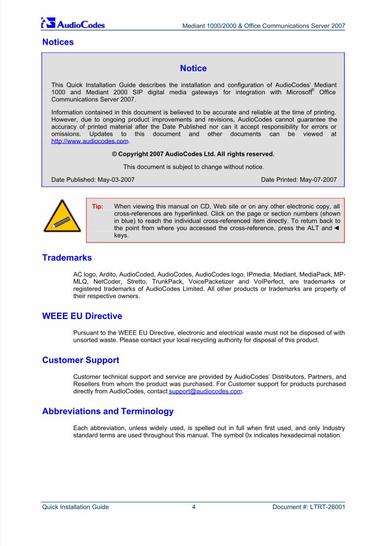
Notices
Notice
This Quick Installation Guide describes the installation and configuration of AudioCodes’ Mediant
1000 and Mediant 2000 SIP digital media gateways for integration with Microsoft®
OfficeCommunications Server 2007.
Information contained in this document is believed to be accurate and reliable at the time of printing.However, due to ongoing product improvements and revisions, AudioCodes cannot guarantee theaccuracy of printed material after the Date Published nor can it accept responsibility for errors or omissions. Updates to this document and other documents can be viewed athttp://www.audiocodes.com.
© Copyright 2007 AudioCodes Ltd. All rights reserved.
This document is subject to change without notice.
Date Published: May-03-2007 Date Printed: May-07-2007
Tip: When viewing this manual on CD, Web site or on any other electronic copy, allcross-references are hyperlinked. Click on the page or section numbers (shownin blue) to reach the individual cross-referenced item directly. To return back tothe point from where you accessed the cross-reference, press the ALT and keys.
Trademarks
AC logo, Ardito, AudioCoded, AudioCodes, AudioCodes logo, IPmedia, Mediant, MediaPack, MP-
MLQ, NetCoder, Stretto, TrunkPack, VoicePacketizer and VoIPerfect, are trademarks or registered trademarks of AudioCodes Limited. All other products or trademarks are property of their respective owners.
WEEE EU Directive
Pursuant to the WEEE EU Directive, electronic and electrical waste must not be disposed of withunsorted waste. Please contact your local recycling authority for disposal of this product.
Customer Support
Customer technical support and service are provided by AudioCodes’ Distributors, Partners, andResellers from whom the product was purchased. For Customer support for products purchaseddirectly from AudioCodes, contact [email protected].
Abbreviations and Terminology
Each abbreviation, unless widely used, is spelled out in full when first used, and only Industrystandard terms are used throughout this manual. The symbol 0x indicates hexadecimal notation.
8/2/2019 LTRT-26001 Mediant 1000 and 2000 and MS OCS 2007 Quick Guide Ver 5
http://slidepdf.com/reader/full/ltrt-26001-mediant-1000-and-2000-and-ms-ocs-2007-quick-guide-ver-5 5/44
Quick Installation Guide Notices
Version 5.0 5 May 2007
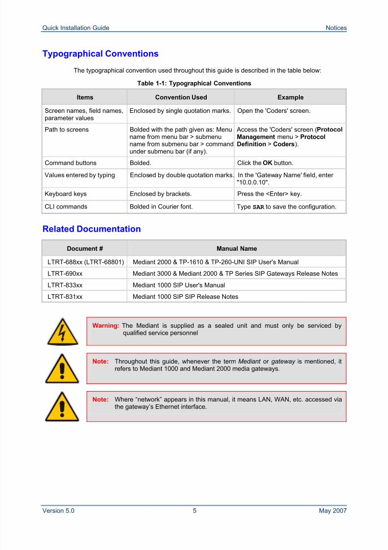
Typographical Conventions
The typographical convention used throughout this guide is described in the table below:
Table 1-1: Typographical Conventions
Items Convention Used Example
Screen names, field names,parameter values
Enclosed by single quotation marks. Open the 'Coders' screen.
Path to screens Bolded with the path given as: Menuname from menu bar > submenuname from submenu bar > commandunder submenu bar (if any).
Access the 'Coders' screen (ProtocolManagement menu > ProtocolDefinition > Coders).
Command buttons Bolded. Click the OK button.
Values entered by typing Enclosed by double quotation marks. In the 'Gateway Name' field, enter "10.0.0.10".
Keyboard keys Enclosed by brackets. Press the <Enter> key.
CLI commands Bolded in Courier font. Type SAR to save the configuration.
Related Documentation
Document # Manual Name
LTRT-688xx (LTRT-68801) Mediant 2000 & TP-1610 & TP-260-UNI SIP User's Manual
LTRT-690xx Mediant 3000 & Mediant 2000 & TP Series SIP Gateways Release Notes
LTRT-833xx Mediant 1000 SIP User's Manual
LTRT-831xx Mediant 1000 SIP SIP Release Notes
Warning: The Mediant is supplied as a sealed unit and must only be serviced byqualified service personnel
Note: Throughout this guide, whenever the term Mediant or gateway is mentioned, itrefers to Mediant 1000 and Mediant 2000 media gateways.
Note: Where “network” appears in this manual, it means LAN, WAN, etc. accessed viathe gateway’s Ethernet interface.
8/2/2019 LTRT-26001 Mediant 1000 and 2000 and MS OCS 2007 Quick Guide Ver 5
http://slidepdf.com/reader/full/ltrt-26001-mediant-1000-and-2000-and-ms-ocs-2007-quick-guide-ver-5 6/44
Mediant 1000/2000 & Office Communications Server 2007
Quick Installation Guide 6 Document #: LTRT-26001
1 Introduction
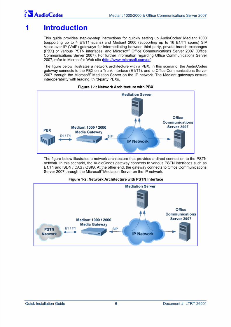
This guide provides step-by-step instructions for quickly setting up AudioCodes' Mediant 1000(supporting up to 4 E1/T1 spans) and Mediant 2000 (supporting up to 16 E1/T1 spans) SIPVoice-over-IP (VoIP) gateways for intermediating between third-party, private branch exchanges(PBX) or various PSTN interfaces, and Microsoft® Office Communications Server 2007 (Office
Communications Server 2007). For further information regarding Office Communications Server 2007, refer to Microsoft's Web site (http://www.microsoft.com/uc).
The figure below illustrates a network architecture with a PBX. In this scenario, the AudioCodesgateway connects to the PBX on a Trunk interface (E1/T1), and to Office Communications Server 2007 through the Microsoft® Mediation Server on the IP network. The Mediant gateways ensureinteroperability with leading, third-party PBXs.
Figure 1-1: Network Architecture with PBX
The figure below illustrates a network architecture that provides a direct connection to the PSTNnetwork. In this scenario, the AudioCodes gateway connects to various PSTN interfaces such as
E1/T1 and ISDN / CAS / QSIG. At the other end, the gateway connects to Office CommunicationsServer 2007 through the Microsoft® Mediation Server on the IP network.
Figure 1-2: Network Architecture with PSTN Interface
8/2/2019 LTRT-26001 Mediant 1000 and 2000 and MS OCS 2007 Quick Guide Ver 5
http://slidepdf.com/reader/full/ltrt-26001-mediant-1000-and-2000-and-ms-ocs-2007-quick-guide-ver-5 7/44
Quick Installation Guide 2. Quick Start
Version 5.0 7 May 2007
2 Quick Start
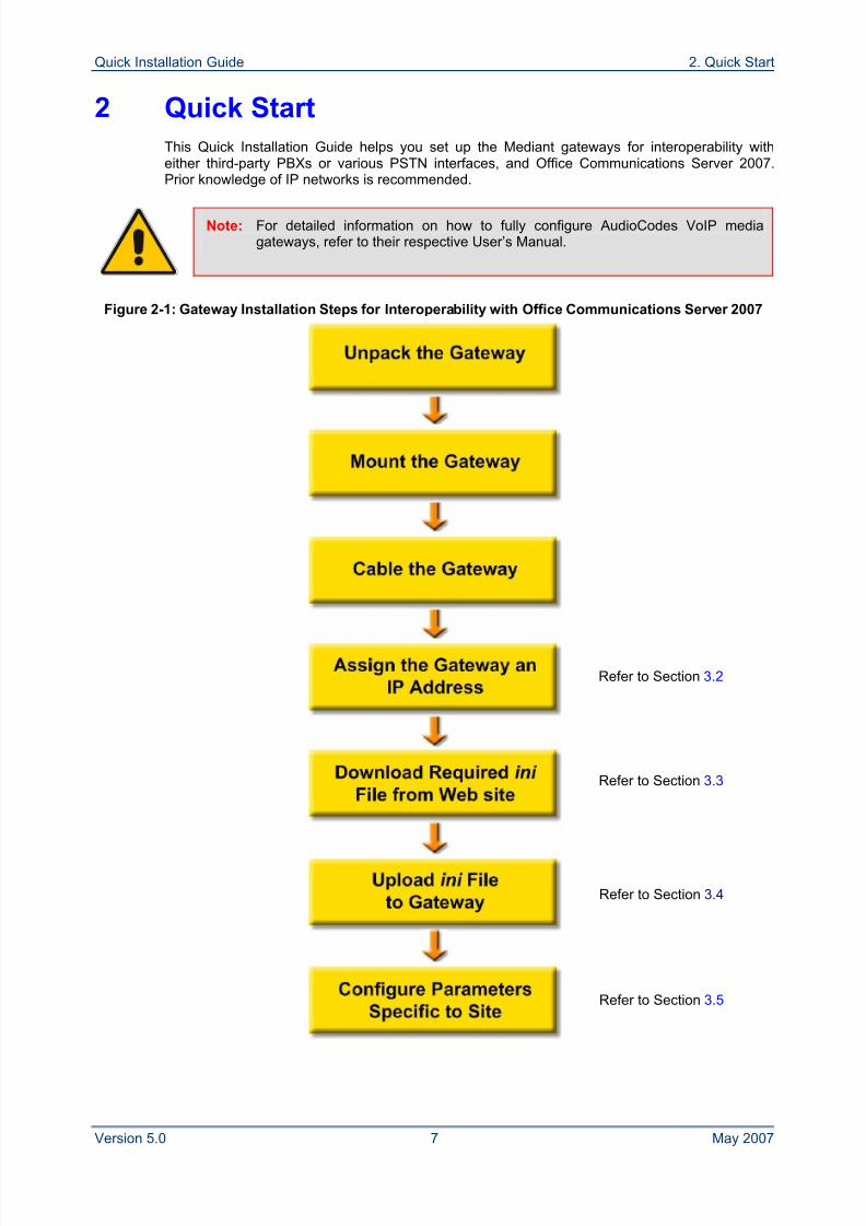
This Quick Installation Guide helps you set up the Mediant gateways for interoperability witheither third-party PBXs or various PSTN interfaces, and Office Communications Server 2007.Prior knowledge of IP networks is recommended.
Note: For detailed information on how to fully configure AudioCodes VoIP mediagateways, refer to their respective User’s Manual.
Figure 2-1: Gateway Installation Steps for Interoperability with Office Communications Server 2007
Refer to Section 3.3
Refer to Section 3.2
Refer to Section 3.4
Refer to Section 3.5
8/2/2019 LTRT-26001 Mediant 1000 and 2000 and MS OCS 2007 Quick Guide Ver 5
http://slidepdf.com/reader/full/ltrt-26001-mediant-1000-and-2000-and-ms-ocs-2007-quick-guide-ver-5 8/44
Mediant 1000/2000 & Office Communications Server 2007
Quick Installation Guide 8 Document #: LTRT-26001
3 Configuring the Gateway
The gateway is supplied with application software already residing on its flash memory (withfactory default parameters).
Note: This guide assumes that the gateway is running firmware version 5.0. If you arerunning an earlier version, please update the version to 5.0. (The firmware canbe obtained from AudioCodes Web site if you are a registered customer, asdescribed in Section 8 on page 37.)
3.1 Embedded Web Server Management Tool
The gateway contains an embedded HTTP server that provides a user-friendly client Webinterface for gateway configuration.
3.1.1 Accessing the Gateway's Embedded Web Server
The gateway's embedded Web server is initially accessed using the default IP address(10.1.10.11) and login username ('Admin') and password ('Admin').
Note: Ensure that your gateway is in the same subnet as the PC running the Webbrowser. If not, refer to Section 3.2 on page 12 for assigning an IP address tothe gateway.
To access the gateway's embedded Web server, take these 4
steps:
1. Open a standard Web-browser such as Microsoft™ Internet Explorer™ (Version 6.0 andhigher) or Netscape™ Navigator™ (Version 7.2 and higher).
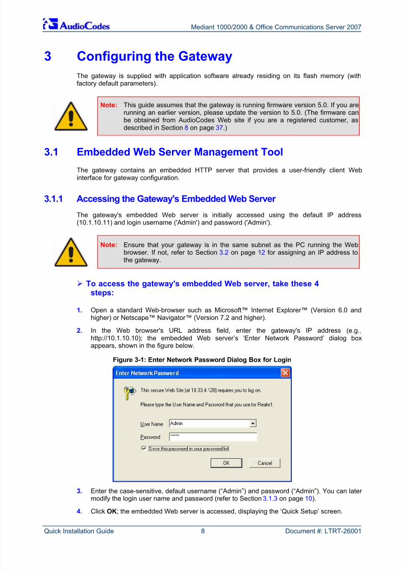
2. In the Web browser's URL address field, enter the gateway's IP address (e.g.,http://10.1.10.10); the embedded Web server’s ‘Enter Network Password’ dialog boxappears, shown in the figure below.
Figure 3-1: Enter Network Password Dialog Box for Login
3. Enter the case-sensitive, default username (“Admin”) and password (“Admin”). You can later modify the login user name and password (refer to Section 3.1.3 on page 10).
4. Click OK; the embedded Web server is accessed, displaying the ‘Quick Setup’ screen.
8/2/2019 LTRT-26001 Mediant 1000 and 2000 and MS OCS 2007 Quick Guide Ver 5
http://slidepdf.com/reader/full/ltrt-26001-mediant-1000-and-2000-and-ms-ocs-2007-quick-guide-ver-5 9/44
Quick Installation Guide 3. Configuring the Gateway
Version 5.0 9 May 2007
3.1.2 Navigating the Embedded Web Server
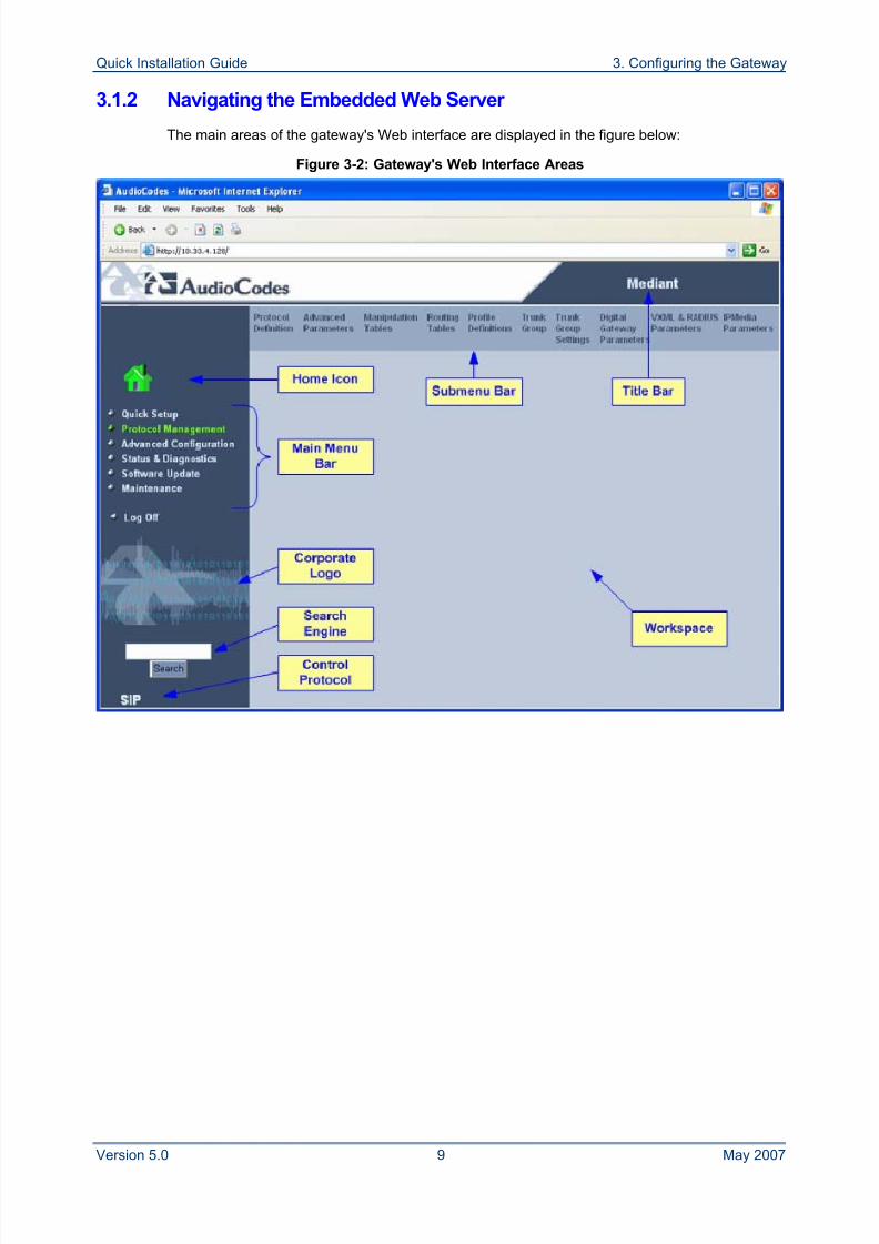
The main areas of the gateway's Web interface are displayed in the figure below:
Figure 3-2: Gateway's Web Interface Areas
8/2/2019 LTRT-26001 Mediant 1000 and 2000 and MS OCS 2007 Quick Guide Ver 5
http://slidepdf.com/reader/full/ltrt-26001-mediant-1000-and-2000-and-ms-ocs-2007-quick-guide-ver-5 10/44
Mediant 1000/2000 & Office Communications Server 2007
Quick Installation Guide 10 Document #: LTRT-26001
3.1.3 Changing Login User Name and Password
It's recommended that you change the default user name and password of the Web user accountthat you initially used to access the embedded Web server.
To change the username and password, take these 4 steps:
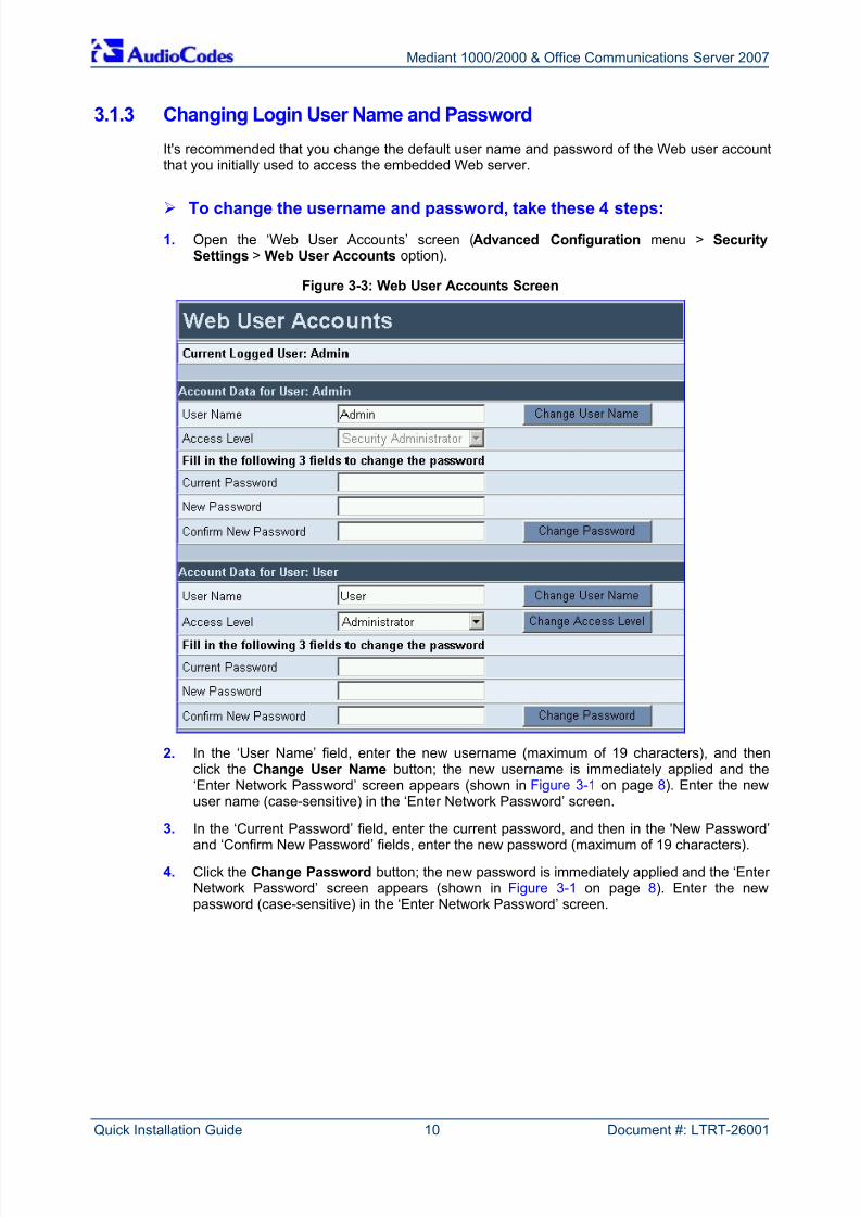
1. Open the ‘Web User Accounts’ screen (Advanced Configuration menu > SecuritySettings > Web User Accounts option).
Figure 3-3: Web User Accounts Screen
2. In the ‘User Name’ field, enter the new username (maximum of 19 characters), and thenclick the Change User Name button; the new username is immediately applied and the‘Enter Network Password’ screen appears (shown in Figure 3-1 on page 8). Enter the newuser name (case-sensitive) in the ‘Enter Network Password’ screen.
3. In the ‘Current Password’ field, enter the current password, and then in the 'New Password’and ‘Confirm New Password’ fields, enter the new password (maximum of 19 characters).
4. Click the Change Password button; the new password is immediately applied and the ‘Enter Network Password’ screen appears (shown in Figure 3-1 on page 8). Enter the newpassword (case-sensitive) in the ‘Enter Network Password’ screen.
8/2/2019 LTRT-26001 Mediant 1000 and 2000 and MS OCS 2007 Quick Guide Ver 5
http://slidepdf.com/reader/full/ltrt-26001-mediant-1000-and-2000-and-ms-ocs-2007-quick-guide-ver-5 11/44
Quick Installation Guide 3. Configuring the Gateway
Version 5.0 11 May 2007
3.1.4 Searching for ini File Parameters
The embedded Web server provides a search engine that allows you to search any ini fileparameter that is configurable using the Web server. The search result provides you with a link tothe relevant Web screen in which the parameter appears. The Search button, located near the
bottom of the Main menu bar (refer to Figure 3-4) is used to perform these parameter searches.You can search for a specific ini file parameter (e.g., 'EnableIPSec') or a sub-string of thatparameter (e.g., 'sec'). If you search for a sub-string, a list of all found parameters that contain thesearched sub-string in their parameter names is displayed.
To search for an ini file parameter configurable by the Web server, takethese 3 steps:
1. In the 'Search' field located in the left pane of the Web page, enter the name or sub-string of the ini parameter for which you want to search.
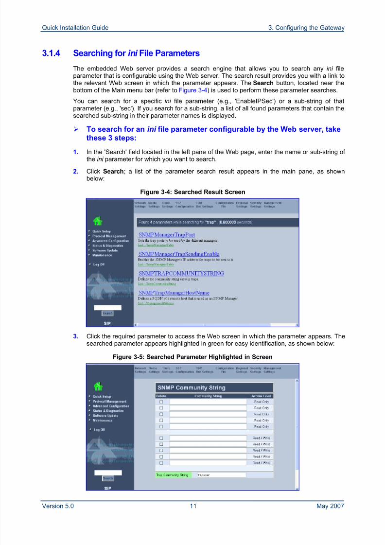
2. Click Search; a list of the parameter search result appears in the main pane, as shownbelow:
Figure 3-4: Searched Result Screen
3. Click the required parameter to access the Web screen in which the parameter appears. Thesearched parameter appears highlighted in green for easy identification, as shown below:
Figure 3-5: Searched Parameter Highlighted in Screen
8/2/2019 LTRT-26001 Mediant 1000 and 2000 and MS OCS 2007 Quick Guide Ver 5
http://slidepdf.com/reader/full/ltrt-26001-mediant-1000-and-2000-and-ms-ocs-2007-quick-guide-ver-5 12/44
Mediant 1000/2000 & Office Communications Server 2007
Quick Installation Guide 12 Document #: LTRT-26001
3.2 Assigning the Gateway an IP Address
The gateway is composed of a media gateway module with its own MAC and IP address. Thetable below lists the gateway's default IP addresses. To assign an IP address to a gatewaymodule, you can use one of the following methods:
BootP (refer to Section 3.2.1 on page 12)
Command Line Interface (CLI) using RS-232 interface (refer to Section 3.2.2 on page 13)
HTTP using a Web browser (refer to Section 3.2.3 on page 13)
DHCP (refer to the gateway's User’s Manual)
You can restore the gateway's networking parameters to factory defaults using the Reset buttonlocated on the gateway's chassis (refer to Section 7.2 on page 35).
Table 3-1: Gateway Default Networking Parameters
Gateway Default Value
IP Address Mediant 1000: 10.1.10.10
Mediant 2000: Spans 1 to 8 = 10.1.10.10; Spans 9 to 16 = 10.1.10.11
Default Subnet Mask 255.255.0.0
Default Gateway IP Address 0.0.0.0
3.2.1 Assigning an IP Address Using BootP
You can use AudioCodes Bootstrap Protocol (BootP) application or any third-party, BootPapplication to assign an IP address to the gateway.
To assign an IP address using BootP, take these 3 steps:
1. Start the BootP application.
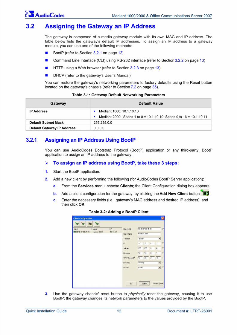
2. Add a new client by performing the following (for AudioCodes BootP Server application):
a. From the Services menu, choose Clients; the Client Configuration dialog box appears.
b. Add a client configuration for the gateway, by clicking the Add New Client button .
c. Enter the necessary fields (i.e., gateway's MAC address and desired IP address), andthen click OK.
Table 3-2: Adding a BootP Client
3. Use the gateway chassis' reset button to physically reset the gateway, causing it to useBootP; the gateway changes its network parameters to the values provided by the BootP.
8/2/2019 LTRT-26001 Mediant 1000 and 2000 and MS OCS 2007 Quick Guide Ver 5
http://slidepdf.com/reader/full/ltrt-26001-mediant-1000-and-2000-and-ms-ocs-2007-quick-guide-ver-5 13/44
Quick Installation Guide 3. Configuring the Gateway
Version 5.0 13 May 2007
3.2.2 Assigning an IP Address Using CLI via RS-232
You can assign an IP address to the gateway using command line interface (CLI) by establishinga serial (RS-232) connection between your PC and the gateway.
Note: For the Mediant 2000, RS-232 interface support depends on the hardwareversion / platform type.
To assign an IP address using CLI via RS-232, take these 6 steps:
1. Connect the gateway's RS-232 port (DB-9 female) to your PC.
2. Use seri al communication software (e.g., HyperTerminalTM) to connect to the gateway withthe following communications port settings: Baud Rate: 115,200 bps; Data bits: 8; Parity:None; Stop bits: 1; Flow control: None.
3. At the CLI prompt, type conf, and then press <Enter>; the configuration folder is accessed.
4. To check the current network parameters, at the prompt, type GCP IP, and then press<Enter>; the current network settings are displayed.
5. Change the network settings by typing the following:
SCP IP [ip_address] [subnet_mask] [default_gateway]
(e.g., SCP IP 10.13.77.7 255.255.0.0 10.13.0.1)
Note: Enter all three network parameters (each separated by a space).
6. To save the configuration, at the prompt, type SAR , and then press <Enter>; the gatewayrestarts with the new network settings. Connectivity is active at the new IP address.
3.2.3 Assigning an IP Address Using HTTP
You can assign an IP address to the gateway using the embedded Web server, by connecting thegateway to a PC with a direct, local Ethernet connection.
To assign an IP address using HTTP, take these 6 steps:
1. Connect the gateway to a PC by performing the following:
a. Disconnect the gateway from the network and reconnect it to your PC using one of the
following two methods:♦ Use a standard Ethernet cable to connect the PC's network interface to a network
hub or switch. Use a second standard Ethernet cable to connect the gateway toanother port on the same network hub or switch.
- Or -
♦ Use an Ethernet cross-over cable to directly connect the PC's network interface tothe gateway.
b. Change your PC’s IP address and subnet mask to correspond with the gateway'sfactory default IP address and subnet mask (listed in Table 3-1).
2. Access the gateway's embedded Web server, (refer to Section 3.1.1 on page 8).
8/2/2019 LTRT-26001 Mediant 1000 and 2000 and MS OCS 2007 Quick Guide Ver 5
http://slidepdf.com/reader/full/ltrt-26001-mediant-1000-and-2000-and-ms-ocs-2007-quick-guide-ver-5 14/44
Mediant 1000/2000 & Office Communications Server 2007
Quick Installation Guide 14 Document #: LTRT-26001
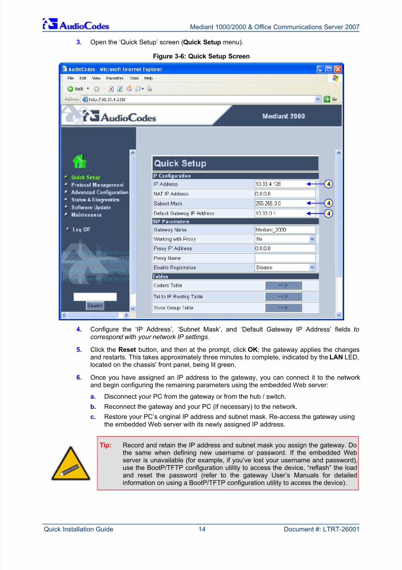
3. Open the ‘Quick Setup’ screen (Quick Setup menu).
Figure 3-6: Quick Setup Screen
4. Configure the ‘IP Address’, ‘Subnet Mask’, and ‘Default Gateway IP Address’ fields tocorrespond with your network IP settings.
5. Click the Reset button, and then at the prompt, click OK; the gateway applies the changesand restarts. This takes approximately three minutes to complete, indicated by the LAN LED,located on the chassis' front panel, being lit green.
6. Once you have assigned an IP address to the gateway, you can connect it to the networkand begin configuring the remaining parameters using the embedded Web server:
a. Disconnect your PC from the gateway or from the hub / switch.
b. Reconnect the gateway and your PC (if necessary) to the network.
c. Restore your PC’s original IP address and subnet mask. Re-access the gateway usingthe embedded Web server with its newly assigned IP address.
Tip: Record and retain the IP address and subnet mask you assign the gateway. Dothe same when defining new username or password. If the embedded Webserver is unavailable (for example, if you’ve lost your username and password),use the BootP/TFTP configuration utility to access the device, “reflash” the loadand reset the password (refer to the gateway User’s Manuals for detailedinformation on using a BootP/TFTP configuration utility to access the device).
4
4
4
8/2/2019 LTRT-26001 Mediant 1000 and 2000 and MS OCS 2007 Quick Guide Ver 5
http://slidepdf.com/reader/full/ltrt-26001-mediant-1000-and-2000-and-ms-ocs-2007-quick-guide-ver-5 15/44
Quick Installation Guide 3. Configuring the Gateway
Version 5.0 15 May 2007
3.3 Obtaining the ini Configuration File from the Web
Before you can load your gateway with the required configuration file (referred to as the ini file),you need to obtain the file from AudioCodes' Web site. From this site, you can also download thelatest User's Manuals, training documentation, firmware, and other files that may be specific to
your deployment (e.g., CAS files).
Notes:
• To ensure that your gateway is configured correctly for interoperability withthe deployed PBX or PSTN interface, ensure that you download the correctini file.
• If your deployment supports T1 CAS, a CAS file is also included in thedownloaded configuration file (zipped file).
• Before you can download firmware files from the Web, you need to register as an AudioCodes customer (refer to Section 8 on page 37).
To download a file to your PC, take these 4 steps:
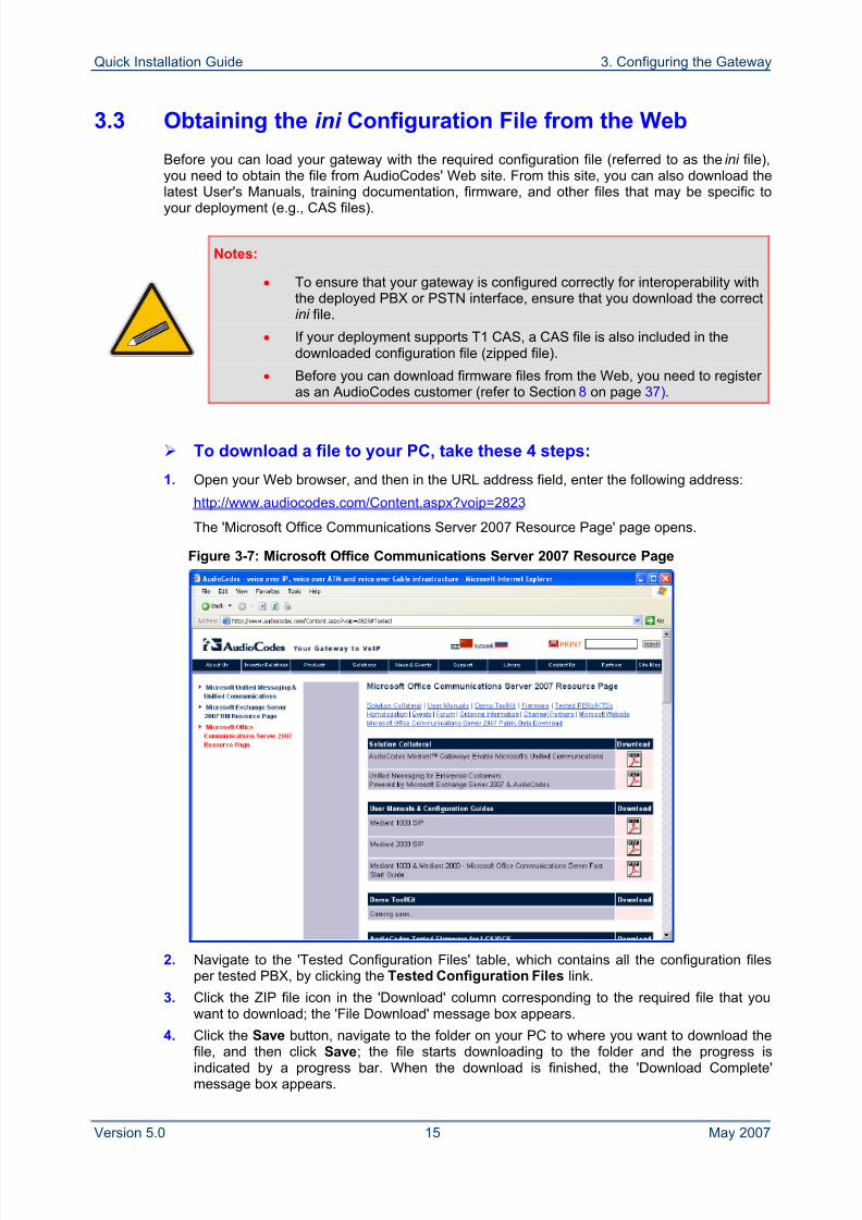
1. Open your Web browser, and then in the URL address field, enter the following address:
http://www.audiocodes.com/Content.aspx?voip=2823
The 'Microsoft Office Communications Server 2007 Resource Page' page opens.
Figure 3-7: Microsoft Office Communications Server 2007 Resource Page
2. Navigate to the 'Tested Configuration Files' table, which contains all the configuration filesper tested PBX, by clicking the Tested Configuration Files link.
3. Click the ZIP file icon in the 'Download' column corresponding to the required file that youwant to download; the 'File Download' message box appears.
4. Click the Save button, navigate to the folder on your PC to where you want to download thefile, and then click Save; the file starts downloading to the folder and the progress isindicated by a progress bar. When the download is finished, the 'Download Complete'message box appears.
8/2/2019 LTRT-26001 Mediant 1000 and 2000 and MS OCS 2007 Quick Guide Ver 5
http://slidepdf.com/reader/full/ltrt-26001-mediant-1000-and-2000-and-ms-ocs-2007-quick-guide-ver-5 16/44
Mediant 1000/2000 & Office Communications Server 2007
Quick Installation Guide 16 Document #: LTRT-26001
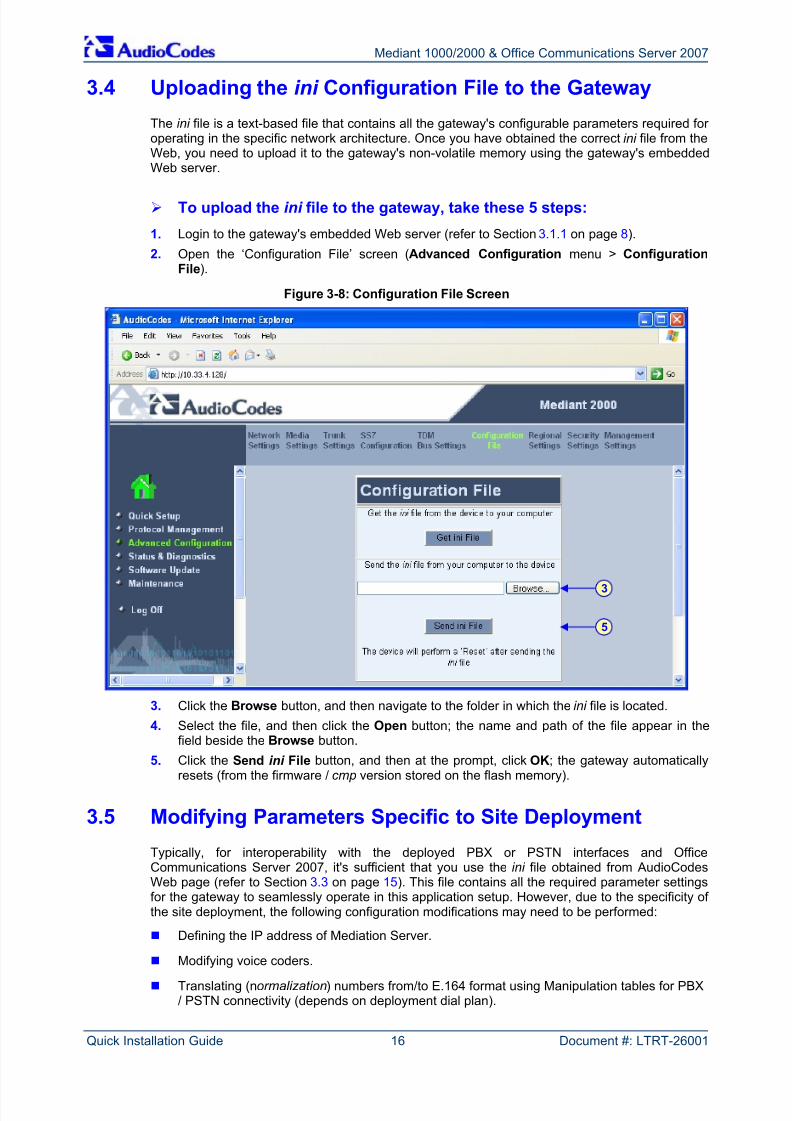
3.4 Uploading the ini Configuration File to the Gateway
The ini file is a text-based file that contains all the gateway's configurable parameters required for operating in the specific network architecture. Once you have obtained the correct ini file from theWeb, you need to upload it to the gateway's non-volatile memory using the gateway's embeddedWeb server.
To upload the ini file to the gateway, take these 5 steps:
1. Login to the gateway's embedded Web server (refer to Section 3.1.1 on page 8).
2. Open the ‘Configuration File’ screen (Advanced Configuration menu > ConfigurationFile).
Figure 3-8: Configuration File Screen
3. Click the Browse button, and then navigate to the folder in which the ini file is located.
4. Select the file, and then click the Open button; the name and path of the file appear in thefield beside the Browse button.
5. Click the Sendini
File button, and then at the prompt, click OK; the gateway automaticallyresets (from the firmware / cmp version stored on the flash memory).
3.5 Modifying Parameters Specific to Site Deployment
Typically, for interoperability with the deployed PBX or PSTN interfaces and OfficeCommunications Server 2007, it's sufficient that you use the ini file obtained from AudioCodesWeb page (refer to Section 3.3 on page 15). This file contains all the required parameter settingsfor the gateway to seamlessly operate in this application setup. However, due to the specificity of the site deployment, the following configuration modifications may need to be performed:
Defining the IP address of Mediation Server.
Modifying voice coders.
Translating (normalization) numbers from/to E.164 format using Manipulation tables for PBX/ PSTN connectivity (depends on deployment dial plan).
3
5
8/2/2019 LTRT-26001 Mediant 1000 and 2000 and MS OCS 2007 Quick Guide Ver 5
http://slidepdf.com/reader/full/ltrt-26001-mediant-1000-and-2000-and-ms-ocs-2007-quick-guide-ver-5 17/44
Quick Installation Guide 3. Configuring the Gateway
Version 5.0 17 May 2007
Modifying Trunk settings including TDM Bus Settings.
Uploading the CAS file to the gateway (if deployment supports CAS).
Modifying QSIG/ISDN parameters (if deployment supports QSIG/ISDN).
Tip: Once the gateway is configured, backup your settings by saving a copy of the
VoIP gateway configuration (ini ) in a directory on your PC (refer to Section 5 onpage 30). This saved file can later be used, if necessary, to restore configurationsettings (refer to Section 3.4 on page 16).
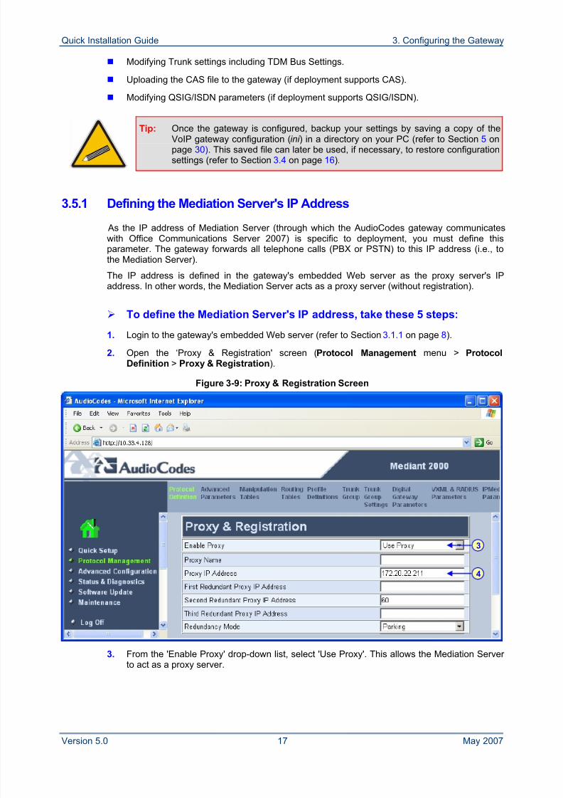
3.5.1 Defining the Mediation Server's IP Address
As the IP address of Mediation Server (through which the AudioCodes gateway communicateswith Office Communications Server 2007) is specific to deployment, you must define thisparameter. The gateway forwards all telephone calls (PBX or PSTN) to this IP address (i.e., tothe Mediation Server).
The IP address is defined in the gateway's embedded Web server as the proxy server's IPaddress. In other words, the Mediation Server acts as a proxy server (without registration).
To define the Mediation Server's IP address, take these 5 steps:
1. Login to the gateway's embedded Web server (refer to Section 3.1.1 on page 8).
2. Open the ‘Proxy & Registration' screen (Protocol Management menu > ProtocolDefinition > Proxy & Registration).
Figure 3-9: Proxy & Registration Screen
3. From the 'Enable Proxy' drop-down list, select 'Use Proxy'. This allows the Mediation Server to act as a proxy server.
3
4
8/2/2019 LTRT-26001 Mediant 1000 and 2000 and MS OCS 2007 Quick Guide Ver 5
http://slidepdf.com/reader/full/ltrt-26001-mediant-1000-and-2000-and-ms-ocs-2007-quick-guide-ver-5 18/44
Mediant 1000/2000 & Office Communications Server 2007
Quick Installation Guide 18 Document #: LTRT-26001
4. In the 'Proxy IP Address' field, enter the IP address (or FQDN) of the Mediation Server.Note: When using FQDN, ensure that you define the DNS server's IP address (in the 'IPSettings' screen -- Advanced Configuration > Network Settings > IP Settings) or theMediation Server's domain name and corresponding IP address (in the 'Internal DNS Table'screen -- Protocol Management > Routing Tables > Internal DNS Table).
5. Click Submit.
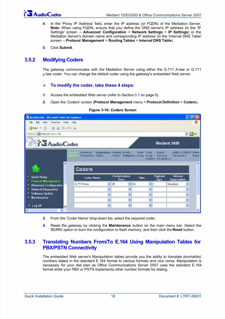
3.5.2 Modifying Coders
The gateway communicates with the Mediation Server using either the G.711 A-law or G.711μ-law coder. You can change the default coder using the gateway's embedded Web server.
To modify the coder, take these 4 steps:
1. Access the embedded Web server (refer to Section 3.1 on page 8).
2. Open the ‘Coders' screen (Protocol Management menu > Protocol Definition > Coders).
Figure 3-10: Coders Screen
3. From the 'Coder Name' drop-down list, select the required coder.
4. Reset the gateway by clicking the Maintenance button on the main menu bar. Select the'BURN' option to burn the configuration to flash memory, and then click the Reset button.
3.5.3 Translating Numbers From/To E.164 Using Manipulation Tables for PBX/PSTN Connectivity
The embedded Web server's Manipulation tables provide you the ability to translate (normalize)numbers dialed in the standard E.164 format to various formats and vice versa. Manipulation isnecessary for your dial plan as Office Communications Server 2007 uses the standard E.164format while your PBX or PSTN implements other number formats for dialing.
8/2/2019 LTRT-26001 Mediant 1000 and 2000 and MS OCS 2007 Quick Guide Ver 5
http://slidepdf.com/reader/full/ltrt-26001-mediant-1000-and-2000-and-ms-ocs-2007-quick-guide-ver-5 19/44
Quick Installation Guide 3. Configuring the Gateway
Version 5.0 19 May 2007
Due to Office Communications Server 2007normalization rules, the gateway may need to performnumber manipulation for outbound (calls received from Microsoft® Office Communicator 2007client via Office Communications Server 2007) and inbound (calls destined for OfficeCommunicator client) calls. If the gateway is connected to a PBX or directly to the PSTN, thegateway may need to perform number manipulations for the called and/or calling number tomatch the PBX or PSTN interfaces dialing rules or to match Office Communications Server 2007's E.164 standard format.
Manipulation number configuration examples are provided for inbound and outbound calls inSection 3.5.3.3 on page 22.
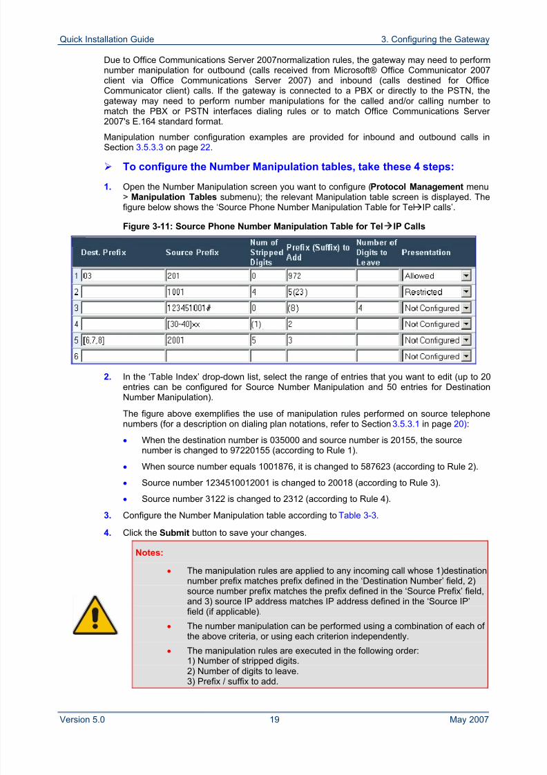
To configure the Number Manipulation tables, take these 4 steps:
1. Open the Number Manipulation screen you want to configure (Protocol Management menu> Manipulation Tables submenu); the relevant Manipulation table screen is displayed. Thefigure below shows the ‘Source Phone Number Manipulation Table for TelIP calls’.
Figure 3-11: Source Phone Number Manipulation Table for TelIP Calls
2. In the ‘Table Index’ drop-down list, select the range of entries that you want to edit (up to 20entries can be configured for Source Number Manipulation and 50 entries for Destination
Number Manipulation).The figure above exemplifies the use of manipulation rules performed on source telephonenumbers (for a description on dialing plan notations, refer to Section 3.5.3.1 in page 20):
• When the destination number is 035000 and source number is 20155, the sourcenumber is changed to 97220155 (according to Rule 1).
• When source number equals 1001876, it is changed to 587623 (according to Rule 2).
• Source number 1234510012001 is changed to 20018 (according to Rule 3).
• Source number 3122 is changed to 2312 (according to Rule 4).
3. Configure the Number Manipulation table according to Table 3-3.
4. Click the Submit button to save your changes.
Notes:
• The manipulation rules are applied to any incoming call whose 1)destinationnumber prefix matches prefix defined in the ‘Destination Number’ field, 2)source number prefix matches the prefix defined in the ‘Source Prefix’ field,and 3) source IP address matches IP address defined in the ‘Source IP’field (if applicable).
• The number manipulation can be performed using a combination of each of the above criteria, or using each criterion independently.
• The manipulation rules are executed in the following order:
1) Number of stripped digits.2) Number of digits to leave.3) Prefix / suffix to add.
8/2/2019 LTRT-26001 Mediant 1000 and 2000 and MS OCS 2007 Quick Guide Ver 5
http://slidepdf.com/reader/full/ltrt-26001-mediant-1000-and-2000-and-ms-ocs-2007-quick-guide-ver-5 20/44
Mediant 1000/2000 & Office Communications Server 2007
Quick Installation Guide 20 Document #: LTRT-26001
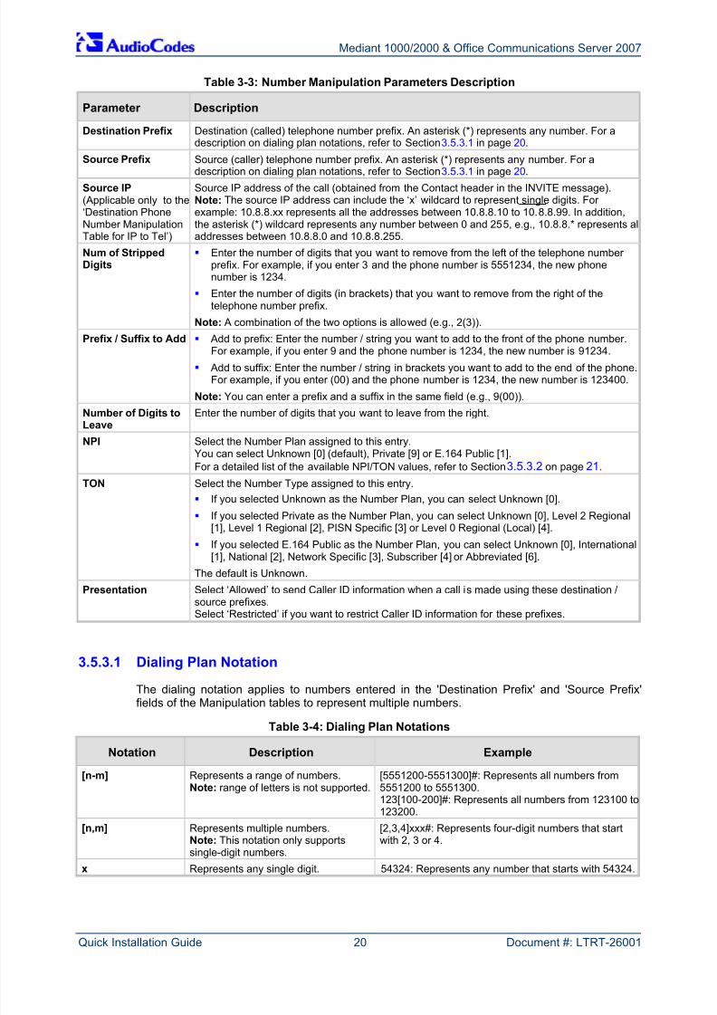
Table 3-3: Number Manipulation Parameters Description
Parameter Description
Destination Prefix Destination (called) telephone number prefix. An asterisk (*) represents any number. For adescription on dialing plan notations, refer to Section 3.5.3.1 in page 20.
Source Prefix Source (caller) telephone number prefix. An asterisk (*) represents any number. For a
description on dialing plan notations, refer to Section 3.5.3.1 in page 20.Source IP(Applicable only to the‘Destination PhoneNumber ManipulationTable for IP to Tel’)
Source IP address of the call (obtained from the Contact header in the INVITE message).Note: The source IP address can include the ‘x’ wildcard to represent single digits. For example: 10.8.8.xx represents all the addresses between 10.8.8.10 to 10.8.8.99. In addition,the asterisk (*) wildcard represents any number between 0 and 255, e.g., 10.8.8.* represents alladdresses between 10.8.8.0 and 10.8.8.255.
Num of StrippedDigits
Enter the number of digits that you want to remove from the left of the telephone number prefix. For example, if you enter 3 and the phone number is 5551234, the new phonenumber is 1234.
Enter the number of digits (in brackets) that you want to remove from the right of thetelephone number prefix.
Note: A combination of the two options is allowed (e.g., 2(3)).
Prefix / Suffix to Add Add to prefix: Enter the number / string you want to add to the front of the phone number.For example, if you enter 9 and the phone number is 1234, the new number is 91234.
Add to suffix: Enter the number / string in brackets you want to add to the end of the phone.For example, if you enter (00) and the phone number is 1234, the new number is 123400.
Note: You can enter a prefix and a suffix in the same field (e.g., 9(00)).
Number of Digits toLeave
Enter the number of digits that you want to leave from the right.
NPI Select the Number Plan assigned to this entry.You can select Unknown [0] (default), Private [9] or E.164 Public [1].For a detailed list of the available NPI/TON values, refer to Section 3.5.3.2 on page 21.
TON Select the Number Type assigned to this entry.
If you selected Unknown as the Number Plan, you can select Unknown [0].
If you selected Private as the Number Plan, you can select Unknown [0], Level 2 Regional[1], Level 1 Regional [2], PISN Specific [3] or Level 0 Regional (Local) [4].
If you selected E.164 Public as the Number Plan, you can select Unknown [0], International[1], National [2], Network Specific [3], Subscriber [4] or Abbreviated [6].
The default is Unknown.
Presentation Select ‘Allowed’ to send Caller ID information when a call is made using these destination /source prefixes.Select ‘Restricted’ if you want to restrict Caller ID information for these prefixes.
3.5.3.1 Dialing Plan Notation
The dialing notation applies to numbers entered in the 'Destination Prefix' and 'Source Prefix'fields of the Manipulation tables to represent multiple numbers.
Table 3-4: Dialing Plan Notations
Notation Description Example
[n-m] Represents a range of numbers.Note: range of letters is not supported.
[5551200-5551300]#: Represents all numbers from5551200 to 5551300.123[100-200]#: Represents all numbers from 123100 to123200.
[n,m] Represents multiple numbers.Note: This notation only supportssingle-digit numbers.
[2,3,4]xxx#: Represents four-digit numbers that startwith 2, 3 or 4.
x Represents any single digit. 54324: Represents any number that starts with 54324.
8/2/2019 LTRT-26001 Mediant 1000 and 2000 and MS OCS 2007 Quick Guide Ver 5
http://slidepdf.com/reader/full/ltrt-26001-mediant-1000-and-2000-and-ms-ocs-2007-quick-guide-ver-5 21/44
Quick Installation Guide 3. Configuring the Gateway
Version 5.0 21 May 2007
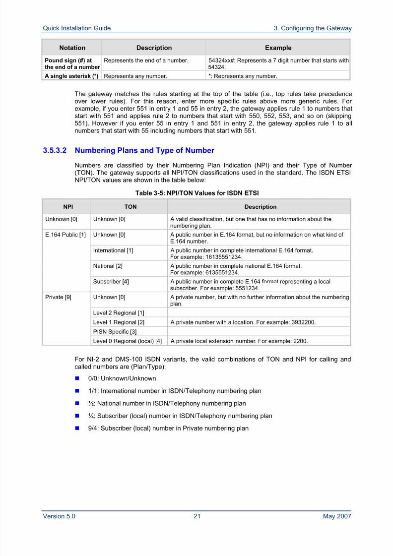
Notation Description Example
Pound sign (#) atthe end of a number
Represents the end of a number. 54324xx#: Represents a 7 digit number that starts with54324.
A single asterisk (*) Represents any number. *: Represents any number.
The gateway matches the rules starting at the top of the table (i.e., top rules take precedenceover lower rules). For this reason, enter more specific rules above more generic rules. For example, if you enter 551 in entry 1 and 55 in entry 2, the gateway applies rule 1 to numbers thatstart with 551 and applies rule 2 to numbers that start with 550, 552, 553, and so on (skipping551). However if you enter 55 in entry 1 and 551 in entry 2, the gateway applies rule 1 to allnumbers that start with 55 including numbers that start with 551.
3.5.3.2 Numbering Plans and Type of Number
Numbers are classified by their Numbering Plan Indication (NPI) and their Type of Number (TON). The gateway supports all NPI/TON classifications used in the standard. The ISDN ETSINPI/TON values are shown in the table below:
Table 3-5: NPI/TON Values for ISDN ETSI
NPI TON Description
Unknown [0] Unknown [0] A valid classification, but one that has no information about thenumbering plan.
Unknown [0] A public number in E.164 format, but no information on what kind of E.164 number.
International [1] A public number in complete international E.164 format.For example: 16135551234.
National [2] A public number in complete national E.164 format.For example: 6135551234.
E.164 Public [1]
Subscriber [4] A public number in complete E.164 format representing a localsubscriber. For example: 5551234.
Unknown [0] A private number, but with no further information about the numberingplan.
Level 2 Regional [1]
Level 1 Regional [2] A private number with a location. For example: 3932200.
PISN Specific [3]
Private [9]
Level 0 Regional (local) [4] A private local extension number. For example: 2200.
For NI-2 and DMS-100 ISDN variants, the valid combinations of TON and NPI for calling andcalled numbers are (Plan/Type):
0/0: Unknown/Unknown 1/1: International number in ISDN/Telephony numbering plan
½: National number in ISDN/Telephony numbering plan
¼: Subscriber (local) number in ISDN/Telephony numbering plan
9/4: Subscriber (local) number in Private numbering plan
8/2/2019 LTRT-26001 Mediant 1000 and 2000 and MS OCS 2007 Quick Guide Ver 5
http://slidepdf.com/reader/full/ltrt-26001-mediant-1000-and-2000-and-ms-ocs-2007-quick-guide-ver-5 22/44
Mediant 1000/2000 & Office Communications Server 2007
Quick Installation Guide 22 Document #: LTRT-26001
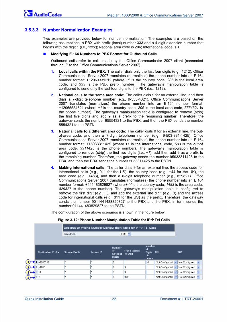
3.5.3.3 Number Normalization Examples
Two examples are provided below for number normalization. The examples are based on thefollowing assumptions: a PBX with prefix (local) number 333 and a 4-digit extension number thatbegins with the digit 1 (i.e., 1xxx); National area code is 206; International code is 1.
Modifying E.164 Numbers to PBX Format for Outbound CallsOutbound calls refer to calls made by the Office Communicator 2007 client (connectedthrough IP to the Office Communications Server 2007).
1. Local calls within the PBX: The caller dials only the last four digits (e.g., 1212). OfficeCommunications Server 2007 translates (normalizes) the phone number into an E.164number format: +12063331212 (where +1 is the country code, 206 is the local areacode, and 333 is the PBX prefix number). The gateway's manipulation table isconfigured to send only the last four digits to the PBX (i.e., 1212).
2. National calls to the same area code: The caller dials 9 for an external line, and thendials a 7-digit telephone number (e.g., 9-555-4321). Office Communications Server 2007 translates (normalizes) the phone number into an E.164 number format:+12065554321 (where +1 is the country code, 206 is the local area code, 5554321 isthe phone number). The gateway's manipulation table is configured to remove (strip)the first five digits and add 9 as a prefix to the remaining number. Therefore, thegateway sends the number 95554321 to the PBX, and then the PBX sends the number 5554321 to the PSTN.
3. National calls to a different area code: The caller dials 9 for an external line, the out-of-area code, and then a 7-digit telephone number (e.g., 9-503-331-1425). OfficeCommunications Server 2007 translates (normalizes) the phone number into an E.164number format: +15033311425 (where +1 is the international code, 503 is the out-of area code, 3311425 is the phone number). The gateway's manipulation table isconfigured to remove (strip) the first two digits (i.e., +1), add then add 9 as a prefix tothe remaining number. Therefore, the gateway sends the number 95033311425 to thePBX, and then the PBX sends the number 5033311425 to the PSTN.
4. Making international calls: The caller dials 9 for an external line, the access code for international calls (e.g., 011 for the US), the country code (e.g., +44 for the UK), thearea code (e.g., 1483), and then a 6-digit telephone number (e.g., 829827). OfficeCommunications Server 2007 translates (normalizes) the phone number into an E.164number format: +441483829827 (where +44 is the country code, 1483 is the area code,829827 is the phone number). The gateway's manipulation table is configured toremove the first digit (e.g., +), and add the external line digit (e.g., 9) and the accesscode for international calls (e.g., 011 for the US) as the prefix. Therefore, the gatewaysends the number 9011441483829827 to the PBX and the PBX, in turn, sends thenumber 011441483829827 to the PSTN.
The configuration of the above scenarios is shown in the figure below:
Figure 3-12: Phone Number Manipulation Table for IPTel Calls
1
2
3
4
8/2/2019 LTRT-26001 Mediant 1000 and 2000 and MS OCS 2007 Quick Guide Ver 5
http://slidepdf.com/reader/full/ltrt-26001-mediant-1000-and-2000-and-ms-ocs-2007-quick-guide-ver-5 23/44
Quick Installation Guide 3. Configuring the Gateway
Version 5.0 23 May 2007
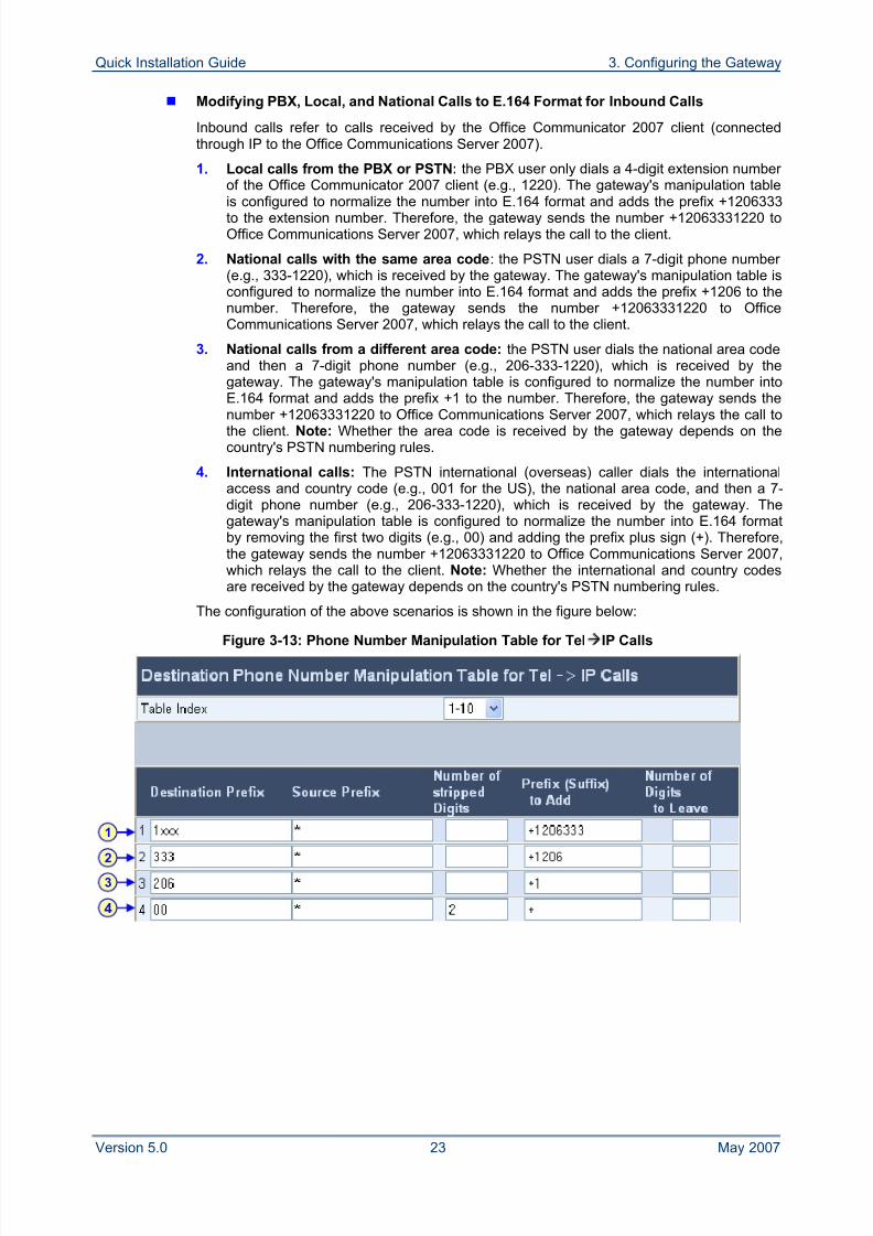
Modifying PBX, Local, and National Calls to E.164 Format for Inbound Calls
Inbound calls refer to calls received by the Office Communicator 2007 client (connectedthrough IP to the Office Communications Server 2007).
1. Local calls from the PBX or PSTN: the PBX user only dials a 4-digit extension number of the Office Communicator 2007 client (e.g., 1220). The gateway's manipulation tableis configured to normalize the number into E.164 format and adds the prefix +1206333to the extension number. Therefore, the gateway sends the number +12063331220 toOffice Communications Server 2007, which relays the call to the client.
2. National calls with the same area code: the PSTN user dials a 7-digit phone number (e.g., 333-1220), which is received by the gateway. The gateway's manipulation table isconfigured to normalize the number into E.164 format and adds the prefix +1206 to thenumber. Therefore, the gateway sends the number +12063331220 to OfficeCommunications Server 2007, which relays the call to the client.
3. National calls from a different area code: the PSTN user dials the national area codeand then a 7-digit phone number (e.g., 206-333-1220), which is received by thegateway. The gateway's manipulation table is configured to normalize the number intoE.164 format and adds the prefix +1 to the number. Therefore, the gateway sends the
number +12063331220 to Office Communications Server 2007, which relays the call tothe client. Note: Whether the area code is received by the gateway depends on thecountry's PSTN numbering rules.
4. International calls: The PSTN international (overseas) caller dials the internationalaccess and country code (e.g., 001 for the US), the national area code, and then a 7-digit phone number (e.g., 206-333-1220), which is received by the gateway. Thegateway's manipulation table is configured to normalize the number into E.164 formatby removing the first two digits (e.g., 00) and adding the prefix plus sign (+). Therefore,the gateway sends the number +12063331220 to Office Communications Server 2007,which relays the call to the client. Note: Whether the international and country codesare received by the gateway depends on the country's PSTN numbering rules.
The configuration of the above scenarios is shown in the figure below:
Figure 3-13: Phone Number Manipulation Table for TelIP Calls
1
2
3
4
8/2/2019 LTRT-26001 Mediant 1000 and 2000 and MS OCS 2007 Quick Guide Ver 5
http://slidepdf.com/reader/full/ltrt-26001-mediant-1000-and-2000-and-ms-ocs-2007-quick-guide-ver-5 24/44
Mediant 1000/2000 & Office Communications Server 2007
Quick Installation Guide 24 Document #: LTRT-26001
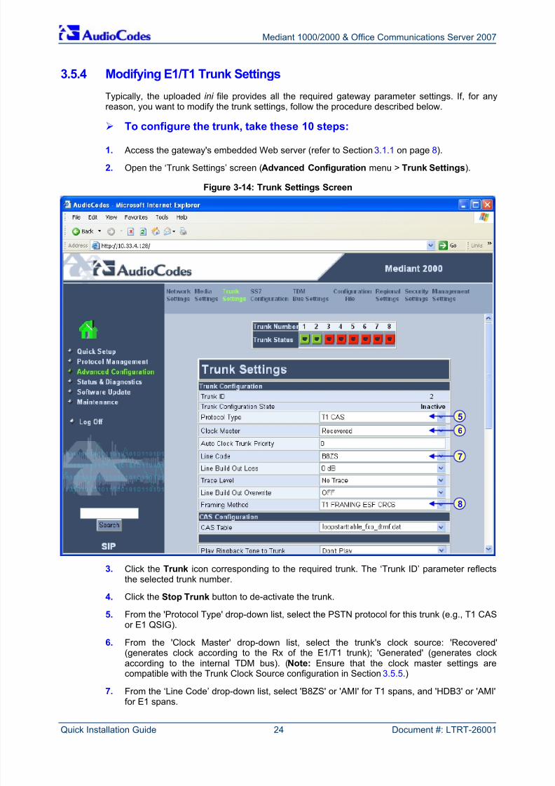
3.5.4 Modifying E1/T1 Trunk Settings
Typically, the uploaded ini file provides all the required gateway parameter settings. If, for anyreason, you want to modify the trunk settings, follow the procedure described below.
To configure the trunk, take these 10 steps:
1. Access the gateway's embedded Web server (refer to Section 3.1.1 on page 8).
2. Open the ‘Trunk Settings’ screen (Advanced Configuration menu > Trunk Settings).
Figure 3-14: Trunk Settings Screen
3. Click the Trunk icon corresponding to the required trunk. The ‘Trunk ID’ parameter reflectsthe selected trunk number.
4. Click the Stop Trunk button to de-activate the trunk.
5. From the 'Protocol Type' drop-down list, select the PSTN protocol for this trunk (e.g., T1 CASor E1 QSIG).
6. From the 'Clock Master' drop-down list, select the trunk's clock source: 'Recovered'(generates clock according to the Rx of the E1/T1 trunk); 'Generated' (generates clockaccording to the internal TDM bus). (Note: Ensure that the clock master settings are
compatible with the Trunk Clock Source configuration in Section 3.5.5.)
7. From the ‘Line Code’ drop-down list, select 'B8ZS' or 'AMI' for T1 spans, and 'HDB3' or 'AMI'for E1 spans.
5
7
8
6
8/2/2019 LTRT-26001 Mediant 1000 and 2000 and MS OCS 2007 Quick Guide Ver 5
http://slidepdf.com/reader/full/ltrt-26001-mediant-1000-and-2000-and-ms-ocs-2007-quick-guide-ver-5 25/44
Quick Installation Guide 3. Configuring the Gateway
Version 5.0 25 May 2007
8. From the ‘Framing Method’ drop-down list, select the framing method for the trunk.
9. Click Apply Trunk Settings to apply the modifications; the trunk becomes active again,indicated by the 'Trunk Configuration State' changing to "Active".
10. Reset the device by clicking the Maintenance button on the main menu bar. Select the'BURN' option to burn the configuration to flash memory, and then click the Reset button.
Note: If the trunk can’t be stopped because it provides the gateway’s clock (assumingthe gateway is synchronized with the E1/T1 clock), assign a different E1/T1 trunkto provide the gateway’s clock, or enable ‘TDM Bus PSTN Auto Clock’ in the'TDM Bus Settings' screen. To assign a different E1/T1 trunk that provides thegateway’s clock, in the ‘TDM Bus Setting’ screen, change the ‘TDM Bus LocalReference’ number to any other trunk number.
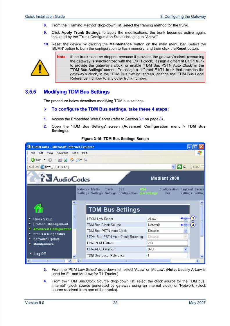
3.5.5 Modifying TDM Bus Settings
The procedure below describes modifying TDM bus settings.
To configure the TDM Bus settings, take these 4 steps:
1. Access the Embedded Web Server (refer to Section 3.1 on page 8).
2. Open the ‘TDM Bus Settings' screen (Advanced Configuration menu > TDM BusSettings).
Figure 3-15: TDM Bus Settings Screen
3. From the 'PCM Law Select' drop-down list, select 'ALaw' or 'MuLaw'. (Note: Usually A-Law isused for E1 and Mu-Law for T1 Trunks.)
4. From the 'TDM Bus Clock Source' drop-down list, select the clock source for the TDM bus:'Internal' (clock source generated by gateway using an internal clock) or 'Network' (clocksource received from one of the trunks).
4
3
8/2/2019 LTRT-26001 Mediant 1000 and 2000 and MS OCS 2007 Quick Guide Ver 5
http://slidepdf.com/reader/full/ltrt-26001-mediant-1000-and-2000-and-ms-ocs-2007-quick-guide-ver-5 26/44
Mediant 1000/2000 & Office Communications Server 2007
Quick Installation Guide 26 Document #: LTRT-26001
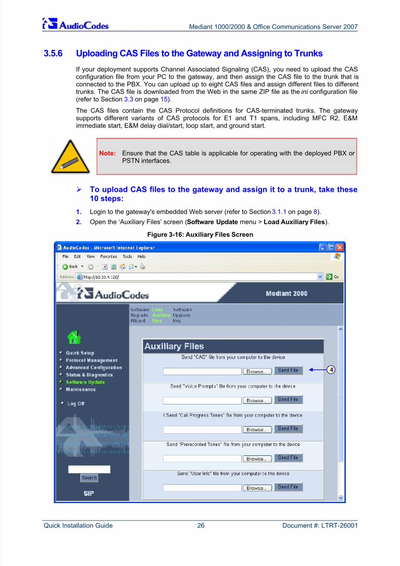
3.5.6 Uploading CAS Files to the Gateway and Assigning to Trunks
If your deployment supports Channel Associated Signaling (CAS), you need to upload the CASconfiguration file from your PC to the gateway, and then assign the CAS file to the trunk that isconnected to the PBX. You can upload up to eight CAS files and assign different files to differenttrunks. The CAS file is downloaded from the Web in the same ZIP file as the ini configuration file(refer to Section 3.3 on page 15).
The CAS files contain the CAS Protocol definitions for CAS-terminated trunks. The gatewaysupports different variants of CAS protocols for E1 and T1 spans, including MFC R2, E&Mimmediate start, E&M delay dial/start, loop start, and ground start.
Note: Ensure that the CAS table is applicable for operating with the deployed PBX or PSTN interfaces.
To upload CAS files to the gateway and assign it to a trunk, take these10 steps:
1. Login to the gateway's embedded Web server (refer to Section 3.1.1 on page 8).
2. Open the ‘Auxiliary Files’ screen (Software Update menu > Load Auxiliary Files).
Figure 3-16: Auxiliary Files Screen
4
8/2/2019 LTRT-26001 Mediant 1000 and 2000 and MS OCS 2007 Quick Guide Ver 5
http://slidepdf.com/reader/full/ltrt-26001-mediant-1000-and-2000-and-ms-ocs-2007-quick-guide-ver-5 27/44
Quick Installation Guide 3. Configuring the Gateway
Version 5.0 27 May 2007
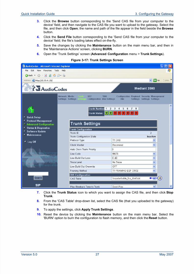
3. Click the Browse button corresponding to the 'Send CAS file from your computer to thedevice' field, and then navigate to the CAS file you want to upload to the gateway. Select thefile, and then click Open; the name and path of the file appear in the field beside the Browse button.
4. Click the Send File button corresponding to the 'Send CAS file from your computer to thedevice' field; the file’s loading takes effect on-the-fly.
5. Save the changes by clicking the Maintenance button on the main menu bar, and then inthe 'Maintenance Actions' screen, clicking BURN.
6. Open the ‘Trunk Settings’ screen (Advanced Configuration menu > Trunk Settings).
Figure 3-17: Trunk Settings Screen
7. Click the Trunk Status icon to which you want to assign the CAS file, and then click StopTrunk.
8. From the 'CAS Table' drop-down list, select the CAS file (that you uploaded to the gateway)for the trunk.
9. To apply the settings, click Apply Trunk Settings.
10. Reset the device by clicking the Maintenance button on the main menu bar. Select the'BURN' option to burn the configuration to flash memory, and then click the Reset button.
8
8/2/2019 LTRT-26001 Mediant 1000 and 2000 and MS OCS 2007 Quick Guide Ver 5
http://slidepdf.com/reader/full/ltrt-26001-mediant-1000-and-2000-and-ms-ocs-2007-quick-guide-ver-5 28/44
Mediant 1000/2000 & Office Communications Server 2007
Quick Installation Guide 28 Document #: LTRT-26001
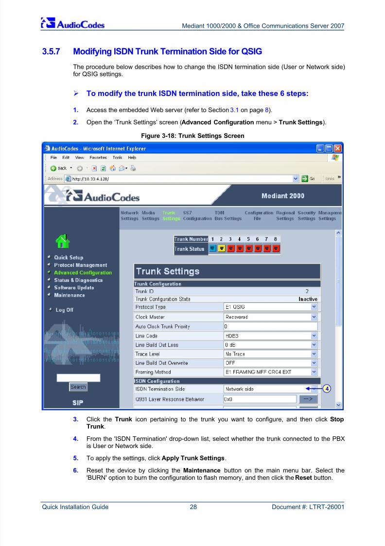
3.5.7 Modifying ISDN Trunk Termination Side for QSIG
The procedure below describes how to change the ISDN termination side (User or Network side)for QSIG settings.
To modify the trunk ISDN termination side, take these 6 steps:
1. Access the embedded Web server (refer to Section 3.1 on page 8).
2. Open the ‘Trunk Settings’ screen (Advanced Configuration menu > Trunk Settings).
Figure 3-18: Trunk Settings Screen
3. Click the Trunk icon pertaining to the trunk you want to configure, and then click StopTrunk.
4. From the 'ISDN Termination' drop-down list, select whether the trunk connected to the PBXis User or Network side.
5. To apply the settings, click Apply Trunk Settings.
6. Reset the device by clicking the Maintenance button on the main menu bar. Select the'BURN' option to burn the configuration to flash memory, and then click the Reset button.
4
8/2/2019 LTRT-26001 Mediant 1000 and 2000 and MS OCS 2007 Quick Guide Ver 5
http://slidepdf.com/reader/full/ltrt-26001-mediant-1000-and-2000-and-ms-ocs-2007-quick-guide-ver-5 29/44
Quick Installation Guide 4. Expanding Deployment with Additional Trunks
Version 5.0 29 May 2007
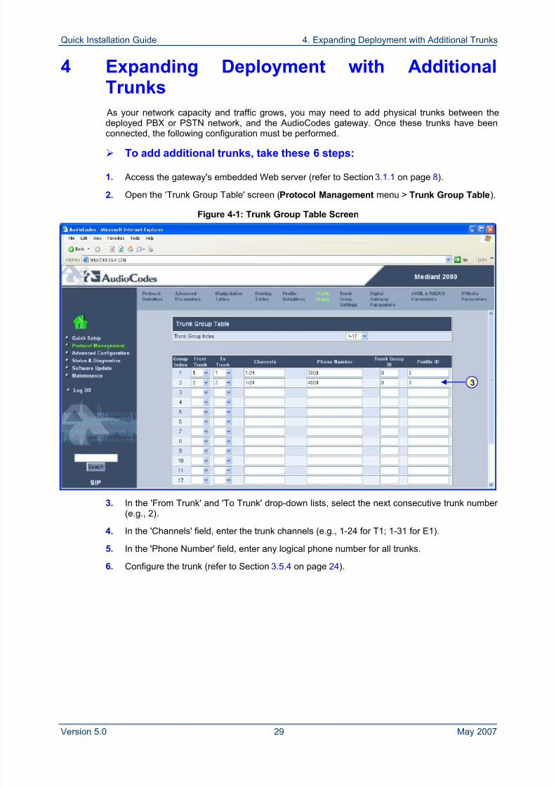
4 Expanding Deployment with AdditionalTrunks
As your network capacity and traffic grows, you may need to add physical trunks between thedeployed PBX or PSTN network, and the AudioCodes gateway. Once these trunks have been
connected, the following configuration must be performed.
To add additional trunks, take these 6 steps:
1. Access the gateway's embedded Web server (refer to Section 3.1.1 on page 8).
2. Open the ‘Trunk Group Table' screen (Protocol Management menu > Trunk Group Table).
Figure 4-1: Trunk Group Table Screen
3. In the 'From Trunk' and 'To Trunk' drop-down lists, select the next consecutive trunk number (e.g., 2).
4. In the 'Channels' field, enter the trunk channels (e.g., 1-24 for T1; 1-31 for E1).
5. In the 'Phone Number' field, enter any logical phone number for all trunks.
6. Configure the trunk (refer to Section 3.5.4 on page 24).
3
8/2/2019 LTRT-26001 Mediant 1000 and 2000 and MS OCS 2007 Quick Guide Ver 5
http://slidepdf.com/reader/full/ltrt-26001-mediant-1000-and-2000-and-ms-ocs-2007-quick-guide-ver-5 30/44
Mediant 1000/2000 & Office Communications Server 2007
Quick Installation Guide 30 Document #: LTRT-26001
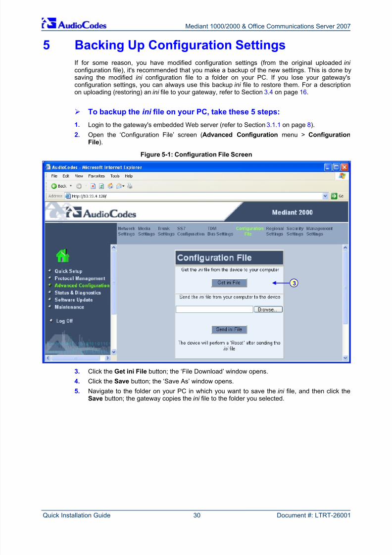
5 Backing Up Configuration Settings
If for some reason, you have modified configuration settings (from the original uploaded ini configuration file), it's recommended that you make a backup of the new settings. This is done bysaving the modified ini configuration file to a folder on your PC. If you lose your gateway'sconfiguration settings, you can always use this backup ini file to restore them. For a description
on uploading (restoring) an ini file to your gateway, refer to Section 3.4 on page 16.
To backup the ini file on your PC, take these 5 steps:
1. Login to the gateway's embedded Web server (refer to Section 3.1.1 on page 8).
2. Open the ‘Configuration File’ screen (Advanced Configuration menu > ConfigurationFile).
Figure 5-1: Configuration File Screen
3. Click the Get ini File button; the ‘File Download’ window opens.
4. Click the Save button; the ‘Save As’ window opens.5. Navigate to the folder on your PC in which you want to save the ini file, and then click the
Save button; the gateway copies the ini file to the folder you selected.
3
8/2/2019 LTRT-26001 Mediant 1000 and 2000 and MS OCS 2007 Quick Guide Ver 5
http://slidepdf.com/reader/full/ltrt-26001-mediant-1000-and-2000-and-ms-ocs-2007-quick-guide-ver-5 31/44
Quick Installation Guide 6. Monitoring the Gateway
Version 5.0 31 May 2007
6 Monitoring the Gateway
6.1 Mediant 2000
The gateway status can be monitored using the following methods:
Monitoring the LEDs (refer to Section 6.1.1 below) on the chassis and TP-1610 board.
Monitoring gateway trunks and B-channels using the embedded Web server (refer to Section6.1.2 on page 32).
6.1.1 Monitoring LEDs
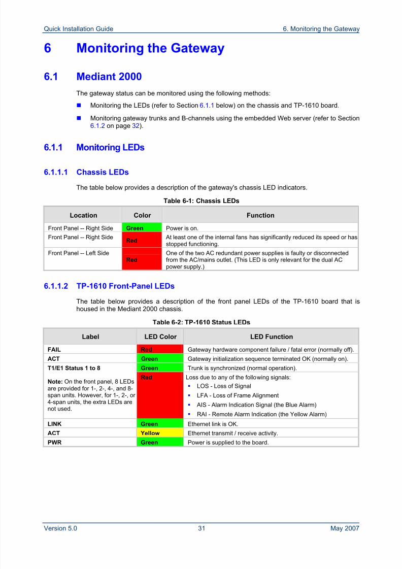
6.1.1.1 Chassis LEDs
The table below provides a description of the gateway's chassis LED indicators.
Table 6-1: Chassis LEDs
Location Color Function
Front Panel -- Right Side Green Power is on.
Front Panel -- Right SideRed
At least one of the internal fans has significantly reduced its speed or hasstopped functioning.
Front Panel -- Left SideRed
One of the two AC redundant power supplies is faulty or disconnectedfrom the AC/mains outlet. (This LED is only relevant for the dual ACpower supply.)
6.1.1.2 TP-1610 Front-Panel LEDs
The table below provides a description of the front panel LEDs of the TP-1610 board that ishoused in the Mediant 2000 chassis.
Table 6-2: TP-1610 Status LEDs
Label LED Color LED Function
FAIL Red Gateway hardware component failure / fatal error (normally off).
ACT Green Gateway initialization sequence terminated OK (normally on).
Green Trunk is synchronized (normal operation).T1/E1 Status 1 to 8
Note: On the front panel, 8 LEDs
are provided for 1-, 2-, 4-, and 8-span units. However, for 1-, 2-, or 4-span units, the extra LEDs arenot used.
Red Loss due to any of the following signals:
LOS - Loss of Signal LFA - Loss of Frame Alignment
AIS - Alarm Indication Signal (the Blue Alarm)
RAI - Remote Alarm Indication (the Yellow Alarm)
LINK Green Ethernet link is OK.
ACT Yellow Ethernet transmit / receive activity.
PWR Green Power is supplied to the board.
8/2/2019 LTRT-26001 Mediant 1000 and 2000 and MS OCS 2007 Quick Guide Ver 5
http://slidepdf.com/reader/full/ltrt-26001-mediant-1000-and-2000-and-ms-ocs-2007-quick-guide-ver-5 32/44
Mediant 1000/2000 & Office Communications Server 2007
Quick Installation Guide 32 Document #: LTRT-26001
6.1.2 Monitoring Trunks and B-Channels
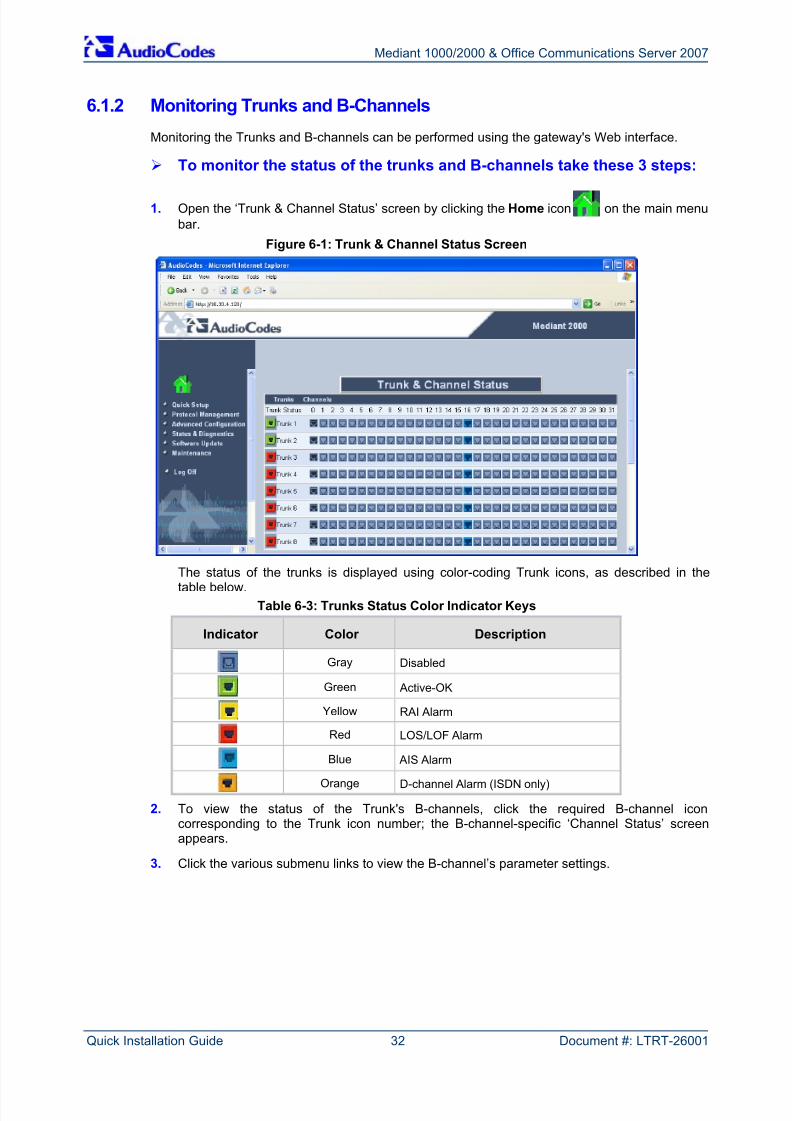
Monitoring the Trunks and B-channels can be performed using the gateway's Web interface.
To monitor the status of the trunks and B-channels take these 3 steps:
1. Open the ‘Trunk & Channel Status’ screen by clicking the Home icon on the main menubar.
Figure 6-1: Trunk & Channel Status Screen
The status of the trunks is displayed using color-coding Trunk icons, as described in thetable below.
Table 6-3: Trunks Status Color Indicator Keys
Indicator Color Description
Gray Disabled
Green Active-OK
Yellow RAI Alarm
Red LOS/LOF Alarm
Blue AIS AlarmOrange D-channel Alarm (ISDN only)
2. To view the status of the Trunk's B-channels, click the required B-channel iconcorresponding to the Trunk icon number; the B-channel-specific ‘Channel Status’ screenappears.
3. Click the various submenu links to view the B-channel’s parameter settings.
8/2/2019 LTRT-26001 Mediant 1000 and 2000 and MS OCS 2007 Quick Guide Ver 5
http://slidepdf.com/reader/full/ltrt-26001-mediant-1000-and-2000-and-ms-ocs-2007-quick-guide-ver-5 33/44
Quick Installation Guide 6. Monitoring the Gateway
Version 5.0 33 May 2007
6.2 Mediant 1000
The gateway status can be monitored using the following methods:
Monitoring the Mediant 1000 chassis LEDs (refer to Section 6.1.1 below).
Monitoring the Mediant 1000 ports (trunks and B-channels, and analog channels) using theembedded Web server (refer to Section 6.1.2 on page 32).
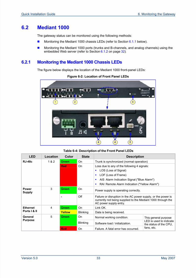
6.2.1 Monitoring the Mediant 1000 Chassis LEDs
The figure below displays the location of the Mediant 1000 front-panel LEDs:
Figure 6-2: Location of Front Panel LEDs
Table 6-4: Description of the Front Panel LEDs
LED Location Color State Description
Green On Trunk is synchronized (normal operation)RJ-48c 1 & 2
Red On Loss due to any of the following 4 signals:
LOS (Loss of Signal)
LOF (Loss of Frame)
AIS Alarm Indication Signal ("Blue Alarm")
RAI Remote Alarm Indication ("Yellow Alarm")
Green On Power supply is operating correctly.Power Supply 3
- Off Failure or disruption in the AC power supply, or the power iscurrently not being supplied to the Mediant 1000 through the AC power supply entry.
Green On Link OK.EthernetPorts I & II
4
Yellow Blinking Data is being received.
On Normal working condition.Green
Blinking Software load / initialization.
GeneralPurpose
5
Red On Failure. A fatal error has occurred.
This general purposeLED is used to indicatethe status of the CPU,fans, etc.
8/2/2019 LTRT-26001 Mediant 1000 and 2000 and MS OCS 2007 Quick Guide Ver 5
http://slidepdf.com/reader/full/ltrt-26001-mediant-1000-and-2000-and-ms-ocs-2007-quick-guide-ver-5 34/44
Mediant 1000/2000 & Office Communications Server 2007
Quick Installation Guide 34 Document #: LTRT-26001
6.2.2 Monitoring the Mediant 1000 Trunks and Channels
The gateway's trunks and channels can be monitored using the gateway's Web interface.
To monitor the status of the Trunks and channels, take these 2 steps:
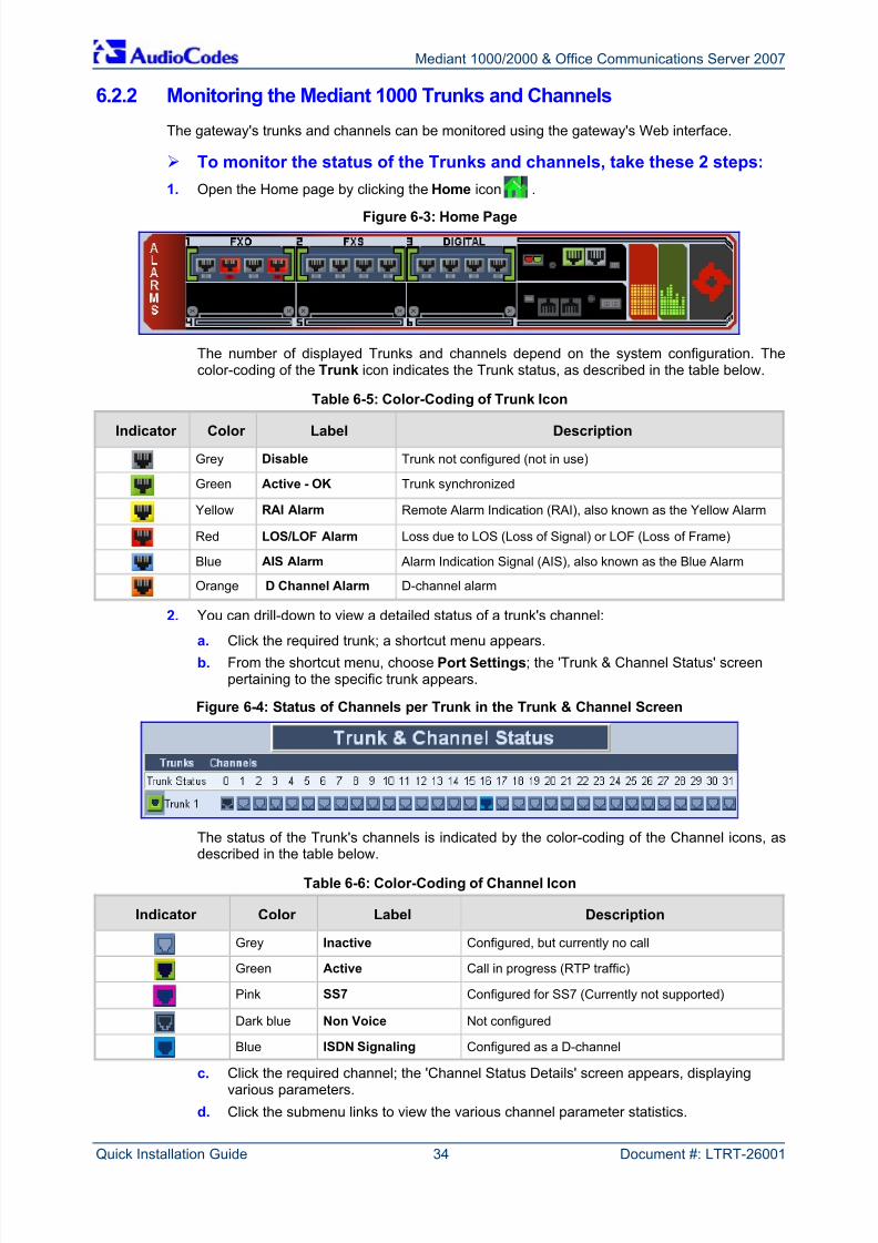
1. Open the Home page by clicking the Home icon .
Figure 6-3: Home Page
The number of displayed Trunks and channels depend on the system configuration. Thecolor-coding of the Trunk icon indicates the Trunk status, as described in the table below.
Table 6-5: Color-Coding of Trunk Icon
Indicator Color Label Description
Grey Disable Trunk not configured (not in use)
Green Active - OK Trunk synchronized
Yellow RAI Alarm Remote Alarm Indication (RAI), also known as the Yellow Alarm
Red LOS/LOF Alarm Loss due to LOS (Loss of Signal) or LOF (Loss of Frame)
Blue AIS Alarm Alarm Indication Signal (AIS), also known as the Blue Alarm
Orange D Channel Alarm D-channel alarm
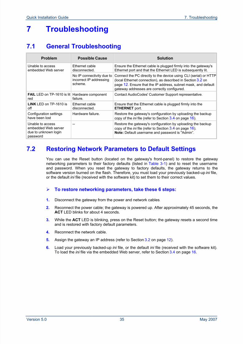
2. You can drill-down to view a detailed status of a trunk's channel:
a. Click the required trunk; a shortcut menu appears.b. From the shortcut menu, choose Port Settings; the 'Trunk & Channel Status' screen
pertaining to the specific trunk appears.
Figure 6-4: Status of Channels per Trunk in the Trunk & Channel Screen
The status of the Trunk's channels is indicated by the color-coding of the Channel icons, asdescribed in the table below.
Table 6-6: Color-Coding of Channel Icon
Indicator Color Label Description
Grey Inactive Configured, but currently no call
Green Active Call in progress (RTP traffic)
Pink SS7 Configured for SS7 (Currently not supported)
Dark blue Non Voice Not configured
Blue ISDN Signaling Configured as a D-channel
c. Click the required channel; the 'Channel Status Details' screen appears, displayingvarious parameters.
d. Click the submenu links to view the various channel parameter statistics.
8/2/2019 LTRT-26001 Mediant 1000 and 2000 and MS OCS 2007 Quick Guide Ver 5
http://slidepdf.com/reader/full/ltrt-26001-mediant-1000-and-2000-and-ms-ocs-2007-quick-guide-ver-5 35/44
Quick Installation Guide 7. Troubleshooting
Version 5.0 35 May 2007
7 Troubleshooting
7.1 General Troubleshooting
Problem Possible Cause Solution
Ethernet cabledisconnected.
Ensure the Ethernet cable is plugged firmly into the gateway'sEthernet port and that the Ethernet LED is subsequently lit.
Unable to accessembedded Web server
No IP connectivity due toincorrect IP addressingscheme.
Connect the PC directly to the device using CLI (serial) or HTTP(local Ethernet connection), as described in Section 3.2 onpage 12. Ensure that the IP address, subnet mask, and defaultgateway addresses are correctly configured.
FAIL LED on TP-1610 is litred
Hardware componentfailure.
Contact AudioCodes' Customer Support representative.
LINK LED on TP-1610 isoff
Ethernet cabledisconnected.
Ensure that the Ethernet cable is plugged firmly into theETHERNET port.
Configuration settings
have been lost
Hardware failure. Restore the gateway's configuration by uploading the backup
copy of the ini file (refer to Section 3.4 on page 16).Unable to accessembedded Web server due to unknown loginpassword
-- Restore the gateway's configuration by uploading the backupcopy of the ini file (refer to Section 3.4 on page 16).Note: Default username and password is "Admin”.
7.2 Restoring Network Parameters to Default Settings
You can use the Reset button (located on the gateway's front-panel) to restore the gatewaynetworking parameters to their factory defaults (listed in Table 3-1) and to reset the usernameand password. When you reset the gateway to factory defaults, the gateway returns to thesoftware version burned on the flash. Therefore, you must load your previously backed-up ini file,
or the default ini file (received with the software kit) to set them to their correct values.
To restore networking parameters, take these 6 steps:
1. Disconnect the gateway from the power and network cables.
2. Reconnect the power cable; the gateway is powered up. After approximately 45 seconds, theACT LED blinks for about 4 seconds.
3. While the ACT LED is blinking, press on the Reset button; the gateway resets a second timeand is restored with factory default parameters.
4. Reconnect the network cable.
5. Assign the gateway an IP address (refer to Section 3.2 on page 12).
6. Load your previously backed-up ini file, or the default ini file (received with the software kit).To load the ini file via the embedded Web server, refer to Section 3.4 on page 16.
8/2/2019 LTRT-26001 Mediant 1000 and 2000 and MS OCS 2007 Quick Guide Ver 5
http://slidepdf.com/reader/full/ltrt-26001-mediant-1000-and-2000-and-ms-ocs-2007-quick-guide-ver-5 36/44
Mediant 1000/2000 & Office Communications Server 2007
Quick Installation Guide 36 Document #: LTRT-26001
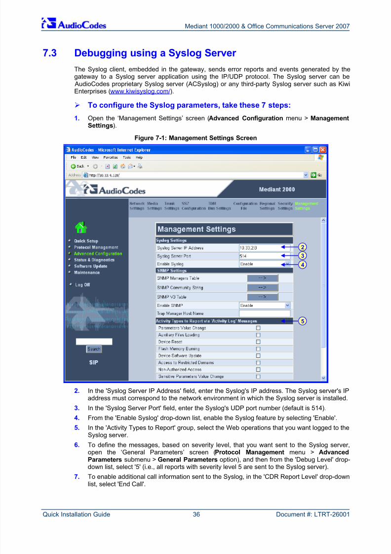
7.3 Debugging using a Syslog Server
The Syslog client, embedded in the gateway, sends error reports and events generated by thegateway to a Syslog server application using the IP/UDP protocol. The Syslog server can be AudioCodes proprietary Syslog server (ACSyslog) or any third-party Syslog server such as Kiwi
Enterprises (www.kiwisyslog.com/). To configure the Syslog parameters, take these 7 steps:
1. Open the ‘Management Settings’ screen (Advanced Configuration menu > ManagementSettings).
Figure 7-1: Management Settings Screen
2. In the 'Syslog Server IP Address' field, enter the Syslog's IP address. The Syslog server's IPaddress must correspond to the network environment in which the Syslog server is installed.
3. In the 'Syslog Server Port' field, enter the Syslog's UDP port number (default is 514).
4. From the 'Enable Syslog' drop-down list, enable the Syslog feature by selecting 'Enable'.
5. In the 'Activity Types to Report' group, select the Web operations that you want logged to theSyslog server.
6. To define the messages, based on severity level, that you want sent to the Syslog server,open the ‘General Parameters’ screen (Protocol Management menu > AdvancedParameters submenu > General Parameters option), and then from the 'Debug Level' drop-down list, select '5' (i.e., all reports with severity level 5 are sent to the Syslog server).
7. To enable additional call information sent to the Syslog, in the 'CDR Report Level' drop-downlist, select 'End Call'.
3
2
4
5
8/2/2019 LTRT-26001 Mediant 1000 and 2000 and MS OCS 2007 Quick Guide Ver 5
http://slidepdf.com/reader/full/ltrt-26001-mediant-1000-and-2000-and-ms-ocs-2007-quick-guide-ver-5 37/44
Quick Installation Guide 8. Customer Registration for Firmware Download
Version 5.0 37 May 2007
8 Customer Registration for FirmwareDownload
Before you can download the gateway's firmware files from AudioCodes' Web site, you need tofirst register online as an AudioCodes' customer. Once registered, you can access and download
the required files using your assigned username and password.
8.1 Registering as a Customer
The registration process includes filling out an online registration form, and subsequentlyreceiving a username and password by e-mail. This username and password can later be used todirectly login as a registered customer and access the firmware files.
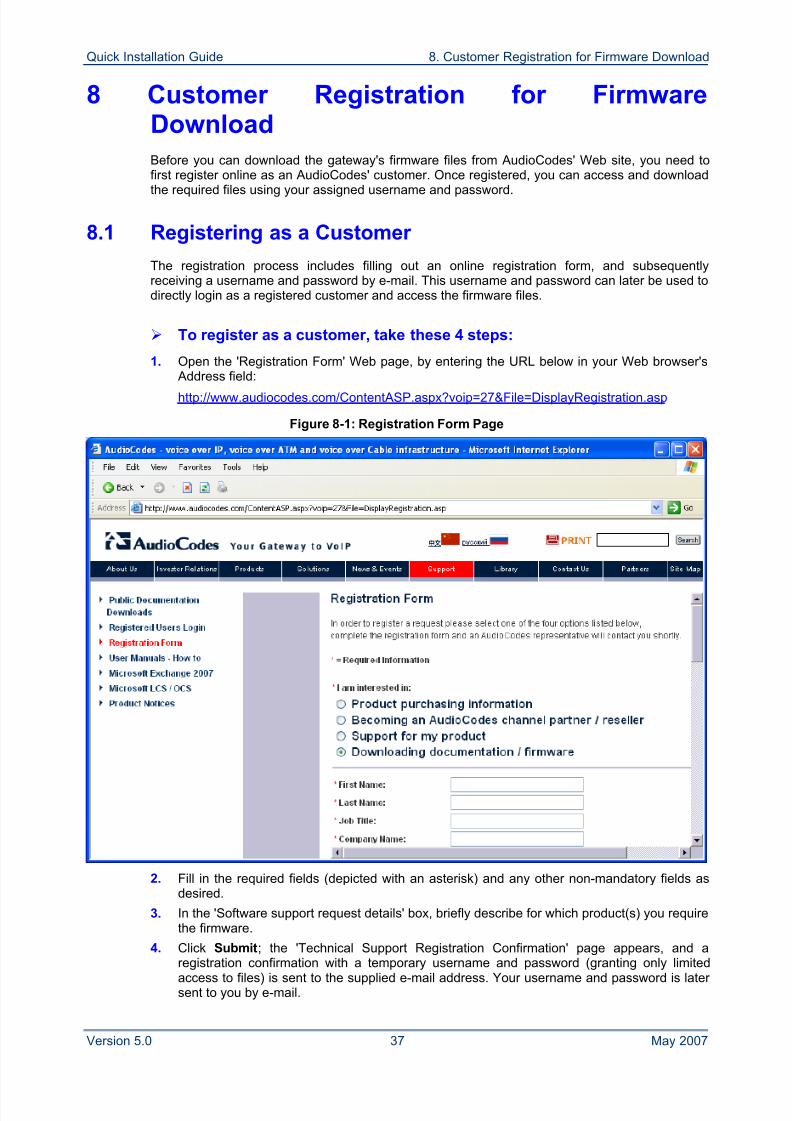
To register as a customer, take these 4 steps:
1. Open the 'Registration Form' Web page, by entering the URL below in your Web browser's
Address field:http://www.audiocodes.com/ContentASP.aspx?voip=27&File=DisplayRegistration.asp
Figure 8-1: Registration Form Page
2. Fill in the required fields (depicted with an asterisk) and any other non-mandatory fields asdesired.
3. In the 'Software support request details' box, briefly describe for which product(s) you requirethe firmware.
4. Click Submit; the 'Technical Support Registration Confirmation' page appears, and aregistration confirmation with a temporary username and password (granting only limitedaccess to files) is sent to the supplied e-mail address. Your username and password is later sent to you by e-mail.
8/2/2019 LTRT-26001 Mediant 1000 and 2000 and MS OCS 2007 Quick Guide Ver 5
http://slidepdf.com/reader/full/ltrt-26001-mediant-1000-and-2000-and-ms-ocs-2007-quick-guide-ver-5 38/44
Mediant 1000/2000 & Office Communications Server 2007
Quick Installation Guide 38 Document #: LTRT-26001
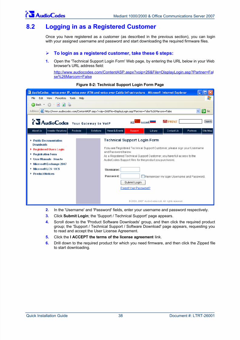
8.2 Logging in as a Registered Customer
Once you have registered as a customer (as described in the previous section), you can loginwith your assigned username and password and start downloading the required firmware files.
To login as a registered customer, take these 6 steps:
1. Open the 'Technical Support Login Form' Web page, by entering the URL below in your Webbrowser's URL address field:
http://www.audiocodes.com/ContentASP.aspx?voip=26&File=DisplayLogin.asp?Partner=False%26Marcom=False
Figure 8-2: Technical Support Login Form Page
2. In the 'Username' and 'Password' fields, enter your username and password respectively.
3. Click Submit Login; the 'Support / Technical Support' page appears.
4. Scroll down to the 'Product Software Downloads' group, and then click the required productgroup; the 'Support / Technical Support / Software Download' page appears, requesting you
to read and accept the User License Agreement.5. Click the I ACCEPT the terms of the license agreement link.
6. Drill down to the required product for which you need firmware, and then click the Zipped fileto start downloading.
http://www.audiocodes.com/ContentASP.aspx?voip=26&File=DisplayLogin.asp?Partner=False%26Marcom=False
http://www.audiocodes.com/ContentASP.aspx?voip=26&File=DisplayLogin.asp?Partner=False%26Marcom=False
8/2/2019 LTRT-26001 Mediant 1000 and 2000 and MS OCS 2007 Quick Guide Ver 5
http://slidepdf.com/reader/full/ltrt-26001-mediant-1000-and-2000-and-ms-ocs-2007-quick-guide-ver-5 39/44
Quick Installation Guide 9. Regulatory Information
Version 5.0 39 May 2007
9 Regulatory Information
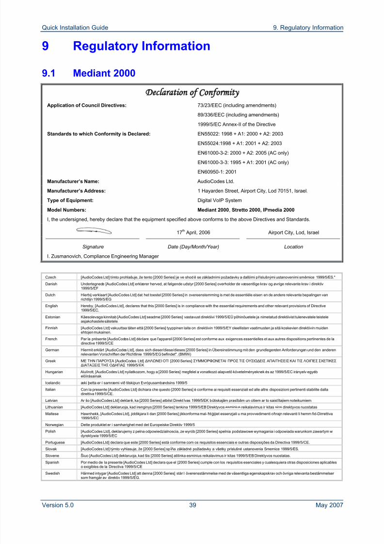
9.1 Mediant 2000
Declaration of Conformity Application of Council Directives: 73/23/EEC (including amendments)
89/336/EEC (including amendments)
1999/5/EC Annex-II of the Directive
Standards to which Conformity is Declared: EN55022: 1998 + A1: 2000 + A2: 2003
EN55024:1998 + A1: 2001 + A2: 2003
EN61000-3-2: 2000 + A2: 2005 (AC only)
EN61000-3-3: 1995 + A1: 2001 (AC only)
EN60950-1: 2001
Manufacturer’s Name: AudioCodes Ltd.
Manufacturer’s Address: 1 Hayarden Street, Airport City, Lod 70151, Israel.
Type of Equipment: Digital VoIP System
Model Numbers: Mediant 2000, Stretto 2000, IPmedia 2000
I, the undersigned, hereby declare that the equipment specified above conforms to the above Directives and Standards.
17th April, 2006 Airport City, Lod, Israel
Signature Date (Day/Month/Year) Location
I. Zusmanovich, Compliance Engineering Manager
Czech [AudioCodes Ltd] tímto prohlašuje, že tento [2000 Series] je ve shodě se základními požadavky a dalšími př íslušnými ustanoveními směrnice 1999/5/ES."Danish Undertegnede [AudioCodes Ltd] erklærer herved, at følgende udstyr [2000 Series] overholder de væsentlige krav og øvrige relevante krav i direktiv
1999/5/EF
Dutch Hierbij verklaart [AudioCodes Ltd] dat het toestel [2000 Series] in overeenstemming is met de essentiële eisen en de andere relevante bepalingen vanrichtlijn 1999/5/EG
English Hereby, [AudioCodes Ltd], declares that this [2000 Series] is in compliance with the essential requirements and other relevant provisions of Directive1999/5/EC.
Estonian Käesolevaga kinnitab [AudioCodes Ltd] seadme [2000 Series] vastavust direktiivi 1999/5/EÜ põhinõuetele ja nimetatud direktiivist tulenevatele teisteleasjakohastele sätetele.
Finnish [AudioCodes Ltd] vakuuttaa täten että [2000 Series] tyyppinen laite on direktiivin 1999/5/EY oleellisten vaatimusten ja sitä koskevien direktiivin muidenehtojen mukainen.
French Par la présente [AudioCodes Ltd] déclare que l'appareil [2000 Series] est conforme aux exigences essentielles et aux autres dispositions pertinentes de ladirective 1999/5/CE
German Hiermit erklärt [AudioCodes Ltd], dass sich dieser/diese/dieses [2000 Series] in Übereinstimmung mit den grundlegenden Anforderungen und den anderenrelevanten Vorschriften der Richtlinie 1999/5/EG befindet". (BMWi)
Greek ΜΕ ΤΗΝ ΠΑΡΟΥΣΑ [AudioCodes Ltd] ΔΗΛΩΝΕΙ ΟΤΙ [2000 Series] ΣΥΜΜΟΡΦΩΝΕΤΑΙ ΠΡΟΣ ΤΙΣ ΟΥΣΙΩΔΕΙΣ ΑΠΑΙΤΗΣΕΙΣ ΚΑΙ ΤΙΣ ΛΟΙΠΕΣ ΣΧΕΤΙΚΕΣ ΔΙΑΤΑΞΕΙΣ ΤΗΣ ΟΔΗΓΙΑΣ 1999/5/ΕΚ
Hungarian Alulírott, [AudioCodes Ltd] nyilatkozom, hogy a [2000 Series] megfelel a vonatkozó alapvetõ követelményeknek és az 1999/5/EC irányelv egyébelõírásainak
Icelandic æki þetta er í samræmi við tilskipun Evrópusambandsins 1999/5
Italian Con la presente [AudioCodes Ltd] dichiara che questo [2000 Series] è conforme ai requisiti essenziali ed alle altre disposizioni pertinenti stabilite dalladirettiva 1999/5/CE.
Latvian Ar šo [AudioCodes Ltd] deklar ē, ka [2000 Series] atbilst Direkt ī vas 1999/5/EK būtiskajām pras ī bām un citiem ar to saist ī tajiem noteikumiem.
Lithuanian [AudioCodes Ltd] deklaruoja, kad irenginys [2000 Series] tenkina 1999/5/EB Direktyvos esminius reikalavimus ir kitas sios direktyvos nuostatas
Maltese Hawnhekk, [AudioCodes Ltd], jiddikjara li dan [2000 Series] jikkonforma mal-ħtiġijiet essenzjali u ma provvedimenti oħrajn relevanti li hemm fid-Dirrettiva1999/5/EC
Norwegian Dette produktet er i samhørighet med det Europeiske Direktiv 1999/5
Polish [AudioCodes Ltd], deklarujemy z pelna odpowiedzialnoscia, ze wyrób [2000 Series] spelnia podstawowe wymagania i odpowiada warunkom zawartym wdyrektywie 1999/5/EC
Portuguese [AudioCodes Ltd] declara que este [2000 Series] está conforme com os requisitos essenciais e outras disposições da Directiva 1999/5/CE.
Slovak [AudioCodes Ltd] týmto vyhlasuje, že [2000 Series] spĺňa základné požiadavky a všetky príslušné ustanovenia Smernice 1999/5/ES.
Slovene Šiuo [AudioCodes Ltd] deklaruoja, kad šis [2000 Series] atitinka esminius reikalavimus ir kitas 1999/5/EB Direktyvos nuostatas.
Spanish Por medio de la presente [AudioCodes Ltd] declara que el [2000 Series] cumple con los requisitos esenciales y cualesquiera otras disposiciones aplicableso exigibles de la Directiva 1999/5/CE
Swedish Härmed intygar [AudioCodes Ltd] att denna [2000 Series] står I överensstämmelse med de väsentliga egenskapskrav och övriga relevanta bestämmelser som framgår av direktiv 1999/5/EG.
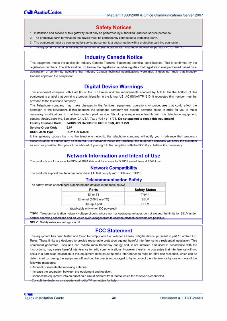
8/2/2019 LTRT-26001 Mediant 1000 and 2000 and MS OCS 2007 Quick Guide Ver 5
http://slidepdf.com/reader/full/ltrt-26001-mediant-1000-and-2000-and-ms-ocs-2007-quick-guide-ver-5 40/44
Mediant 1000/2000 & Office Communications Server 2007
Quick Installation Guide 40 Document #: LTRT-26001
Safety Notices1. Installation and service of this gateway must only be performed by authorized, qualified service personnel.
2. The protective earth terminal on the device must be permanently connected to protective earth.
3. The equipment must be connected by service personnel to a socket-outlet with a protective earthing connection.
4. This equipment should be installed in restricted access locations with maximum allowed temperature 40°C (104°F).
Industry Canada NoticeThis equipment meets the applicable Industry Canada Terminal Equipment technical specifications. This is confirmed by the
registration numbers. The abbreviation, IC, before the registration number signifies that registration was performed based on a
declaration of conformity indicating that Industry Canada technical specifications were met. It does not imply that Industry
Canada approved the equipment.
Digital Device WarningsThis equipment complies with Part 68 of the FCC rules and the requirements adopted by ACTA. On the bottom of this
equipment is a label that contains a product identifier in the format US: AC1ISNANTP1610. If requested this number must be
provided to the telephone company. The Telephone company may make changes in the facilities, equipment, operations or procedures that could affect the
operation of the equipment. If this happens the telephone company will provide advance notice in order for you to makenecessary modifications to maintain uninterrupted service. Should you experience trouble with this telephone equipment,
contact: AudioCodes Inc, San Jose, CA USA. Tel: 1 408 441 1175. Do not attempt to repair this equipment! Facility Interface Code: 04DU9.BN, 04DU9.DN, 04DU9.1KN, 4DU9.ISN
Service Order Code: 6.0F
USOC Jack Type: RJ21X or RJ48C
It this gateway causes harm to the telephone network, the telephone company will notify you in advance that temporary
discontinuance of service may be required. But if advance notice isn’t practical, the telephone company will notify the customer
as soon as possible. Also you will be advised of your right to file complaint with the FCC if you believe it is necessary.
Network Information and Intent of UseThe products are for access to ISDN at 2048 kb/s and for access to G.703 Leased lines at 2048 kb/s.
Network CompatibilityThe products support the Telecom networks in EU that comply with TBR4 and TBR13.
Telecommunication SafetyThe safety status of each port is declared and detailed in the table below:
Ports Safety Status
E1 or T1 TNV-1
Ethernet (100 Base-TX) SELV
DC input port
(applicable only when DC powered)
SELV
TNV-1: Telecommunication network voltage circuits whose normal operating voltages do not exceed the limits for SELV under
normal operating conditions and on which over voltages from telecommunication networks are possible.SELV: Safety extra low voltage circuit.
FCC StatementThis equipment has been tested and found to comply with the limits for a Class B digital device, pursuant to part 15 of the FCC
Rules. These limits are designed to provide reasonable protection against harmful interference in a residential installation. This
equipment generates, uses and can radiate radio frequency energy and, if not installed and used in accordance with the
instructions, may cause harmful interference to radio communications. However there is no guarantee that interference will not
occur in a particular installation. If this equipment does cause harmful interference to radio or television reception, which can be
determined by turning the equipment off and on, the user is encouraged to try to correct the interference by one or more of the
following measures:
- Reorient or relocate the receiving antenna.
- Increase the separation between the equipment and receiver.
- Connect the equipment into an outlet on a circuit different from that to which the receiver is connected.
- Consult the dealer or an experienced radio/TV technician for help.
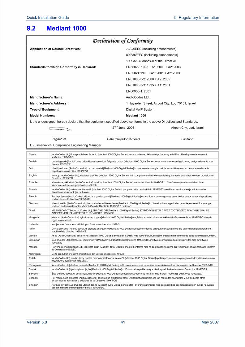
8/2/2019 LTRT-26001 Mediant 1000 and 2000 and MS OCS 2007 Quick Guide Ver 5
http://slidepdf.com/reader/full/ltrt-26001-mediant-1000-and-2000-and-ms-ocs-2007-quick-guide-ver-5 41/44
Quick Installation Guide 9. Regulatory Information
Version 5.0 41 May 2007
9.2 Mediant 1000
Declaration of Conformity
Application of Council Directives: 73/23/EEC (including amendments)
89/336/EEC (including amendments)
1999/5/EC Annex-II of the Directive
Standards to which Conformity is Declared: EN55022: 1998 + A1: 2000 + A2: 2003
EN55024:1998 + A1: 2001 + A2: 2003
EN61000-3-2: 2000 + A2: 2005
EN61000-3-3: 1995 + A1: 2001
EN60950-1: 2001
Manufacturer’s Name: AudioCodes Ltd.
Manufacturer’s Address: 1 Hayarden Street, Airport City, Lod 70151, Israel.
Type of Equipment: Digital VoIP System
Model Numbers: Mediant 1000
I, the undersigned, hereby declare that the equipment specified above conforms to the above Directives and Standards.
27th June, 2006 Airport City, Lod, Israel
Signature Date (Day/Month/Year) Location
I. Zusmanovich, Compliance Engineering Manager
Czech [AudioCodes Ltd] tímto prohlašuje, že tento [Mediant 1000 Digital Series] je ve shodě se základními požadavky a dalšími př íslušnými ustanovenímisměrnice 1999/5/ES."
Danish Undertegnede [AudioCodes Ltd] erklærer herved, at følgende udstyr [Mediant 1000 Digital Series] overholder de væsentlige krav og øvrige relevante krav idirektiv 1999/5/EF
Dutch Hierbij verklaart [AudioCodes Ltd] dat het toestel [Mediant 1000 Digital Series] in overeenstemming is met de essentiële eisen en de andere relevantebepalingen van richtlijn 1999/5/EG
English Hereby, [AudioCodes Ltd], declares that this [Mediant 1000 Digital Series] is in compliance with the essential requirements and other relevant provisions of
Directive 1999/5/EC.
Estonian Käesolevaga kinnitab [AudioCodes Ltd] seadme [Mediant 1000 Digital Series] vastavust direktiivi 1999/5/EÜ põhinõuetele ja nimetatud direktiivisttulenevatele teistele asjakohastele sätetele.
Finnish [AudioCodes Ltd] vakuuttaa täten että [Mediant 1000 Digital Series] tyyppinen laite on direktiivin 1999/5/EY oleellisten vaatimusten ja sitä koskeviendirektiivin muiden ehtojen mukainen.
French Par la présente [AudioCodes Ltd] déclare que l'appareil [Mediant 1000 Digital Series] est conforme aux exigences essentielles et aux autres dispositionspertinentes de la directive 1999/5/CE
German Hiermit erklärt [AudioCodes Ltd], dass sich dieser/diese/dieses [Mediant 1000 Digital Series] in Übereinstimmung mit den grundlegenden Anforderungenund den anderen relevanten Vorschriften der Richtlinie 1999/5/EG befindet".
Greek ΜΕ ΤΗΝ ΠΑΡΟΥΣΑ [AudioCodes Ltd] ΔΗΛΩΝΕΙ ΟΤΙ [Mediant 1000 Digital Series] ΣΥΜΜΟΡΦΩΝΕΤΑΙ ΠΡΟΣ ΤΙΣ ΟΥΣΙΩΔΕΙΣ ΑΠΑΙΤΗΣΕΙΣ ΚΑΙ ΤΙΣ ΛΟΙΠΕΣ ΣΧΕΤΙΚΕΣ ΔΙΑΤΑΞΕΙΣ ΤΗΣ ΟΔΗΓΙΑΣ 1999/5/ΕΚ
Hungarian Alulírott, [AudioCodes Ltd] nyilatkozom, hogy a [Mediant 1000 Digital Series] megfelel a vonatkozó alapvetõ követelményeknek és az 1999/5/EC irányelvegyéb elõírásainak
Icelandic æki þetta er í samræmi við tilskipun Evrópusambandsins 1999/5
Italian Con la presente [AudioCodes Ltd] dichiara che questo [Mediant 1000 Digital Series] è conforme ai requisiti essenziali ed alle altre disposizioni pertinentistabilite dalla direttiva 1999/5/CE.
Latvian Ar šo [AudioCodes Ltd] deklar ē, ka [Mediant 1000 Digital Series] atbilst Direkt ī vas 1999/5/EK būtiskajām pras ī bām un citiem ar to saist ī tajiem noteikumiem.Lithuanian [AudioCodes Ltd] deklaruoja, kad irenginys [Mediant 1000 Digital Series] tenkina 1999/5/EB Direktyvos esminius reikalavimus ir kitas sios direktyvos
nuostatas
Maltese Hawnhekk, [AudioCodes Ltd], jiddikjara li dan [Mediant 1000 Digital Series] jikkonforma mal-ħtiġijiet essenzjali u ma provvedimenti oħrajn relevanti li hemmfid-Dirrettiva 1999/5/EC
Norwegian Dette produktet er i samhørighet med det Europeiske Direktiv 1999/5
Polish [AudioCodes Ltd], deklarujemy z pelna odpowiedzialnoscia, ze wyrób [Mediant 1000 Digital Series] spelnia podstawowe wymagania i odpowiada warunkomzawartym w dyrektywie 1999/5/EC
Portuguese [AudioCodes Ltd] declara que este [Mediant 1000 Digital Series] está conforme com os requisitos essenciais e outras disposições da Directiva 1999/5/CE.
Slovak [AudioCodes Ltd] týmto vyhlasuje, že [Mediant 1000 Digital Series] spĺňa základné požiadavky a všetky príslušné ustanovenia Smernice 1999/5/ES.
Slovene Šiuo [AudioCodes Ltd] deklaruoja, kad šis [Mediant 1000 Digital Series] atitinka esminius reikalavimus ir kitas 1999/5/EB Direktyvos nuostatas.
Spanish Por medio de la presente [AudioCodes Ltd] declara que el [Mediant 1000 Digital Series] cumple con los requisitos esenciales y cualesquiera otrasdisposiciones aplicables o exigibles de la Directiva 1999/5/CE
Swedish Härmed intygar [AudioCodes Ltd] att denna [Mediant 1000 Digital Series] står I överensstämmelse med de väsentliga egenskapskrav och övriga relevantabestämmelser som framgår av direktiv 1999/5/EG.
8/2/2019 LTRT-26001 Mediant 1000 and 2000 and MS OCS 2007 Quick Guide Ver 5
http://slidepdf.com/reader/full/ltrt-26001-mediant-1000-and-2000-and-ms-ocs-2007-quick-guide-ver-5 42/44
Mediant 1000/2000 & Office Communications Server 2007
Quick Installation Guide 42 Document #: LTRT-26001
Safety Notices1. Installation and service of this gateway must only be performed by authorized, qualified service personnel.
2. The equipment must be connected by service personnel to a socket-outlet with a protective earthing connection.
3. This equipment should be installed in restricted access locations with maximum allowed temperature 40°C (104°F).
4. To avoid risk of fire use 26 AWG or higher wiring to connect the telecom ports.
Mediant 1000 iPMX NoticeWhen an iPMX (Pentium) module is used, to comply with Class B limits, a shielded cable should be used for the Ethernet port of
the iPMX.
ACTA Customer information1. This equipment, the VoIP gateway, models Mediant 1000 complies with Part 68 of the FCC Rules and the requirements
adopted by the ACTA. On the bottom of the unit of this equipment is a label that contains among other information, a product
identifier in the format US:AC1ISNANM1KDIG. If requested, this number must be provided to the telephone company.
2. This equipment is designed to be connected to the telephone network using an RJ-48C connector, which is Part 68 compliant.
The service order code (SOC) is 6.0F and the Facility interface codes (FIC) are: 04DU9.1SN, 04DU9.1KN, 04DU9.BN,
04DU9.DN.
3. Should the product causes harm to the telephone network, the telephone company will notify you in advance that temporarydiscontinuance of service may be required. If advance notice is not practical, you will be notified as soon as possible. Also, you
will be advised of your right to fi le a compliant with the FCC if it is necessary.
4. The telephone company may make changes in its facilities, equipment, operations or procedures that could affect the
operation of the equipment. If this happens, the telephone company will provide advance notice in order for you to make
necessary modifications to maintain uninterrupted service.
5. If trouble is experienced with this equipment, for repair or warranty information please contact AudioCodes Inc., 2099
Gateway Place, Suite 500, San Jose, CA, 95110, phone number 1-408-441-1175. If the equipment is causing harm to the
telephone network, the telephone company may request to disconnect the equipment until the problem is resolved.
6. Installation is described in Product installation manual. Connection to Telephone Company-provided coin service is
prohibited. Connection to party lines service is subject to State tariffs.
Network Information and Intent of UseThe products are for access to ISDN at 2048 kb/s and for access to G.703 Leased lines at 2048 kb/s.
Network Compatibility
The products support the Telecom networks in EU that comply with TBR4 and TBR13.
Telecommunication Safety
The safety status of each port is declared and detailed in the table below:Ports Safety Status
E1 or T1 TNV-1
Ethernet (100 Base-TX) SELV
TNV-1: Telecommunication network voltage circuits whose normal operating voltages do not exceed the limits for SELV under
normal operating conditions and on which over voltages from telecommunication networks are possible.SELV: Safety extra low voltage circuit.
FCC StatementThis equipment has been tested and found to comply with the limits for a Class B digital device, pursuant to part 15 of the FCC
Rules. These limits are designed to provide reasonable protection against harmful interference in a residential installation. This
equipment generates, uses and can radiate radio frequency energy and, if not installed and used in accordance with the
instructions, may cause harmful interference to radio communications. However there is no guarantee that interference will not
occur in a particular installation. If this equipment does cause harmful interference to radio or television reception, which can be
determined by turning the equipment off and on, the user is encouraged to try to correct the interference by one or more of the
following measures:
- Reorient or relocate the receiving antenna.
- Increase the separation between the equipment and receiver.- Connect the equipment into an outlet on a circuit different from that to which the receiver is connected.
- Consult the dealer or an experienced radio/TV technician for help.
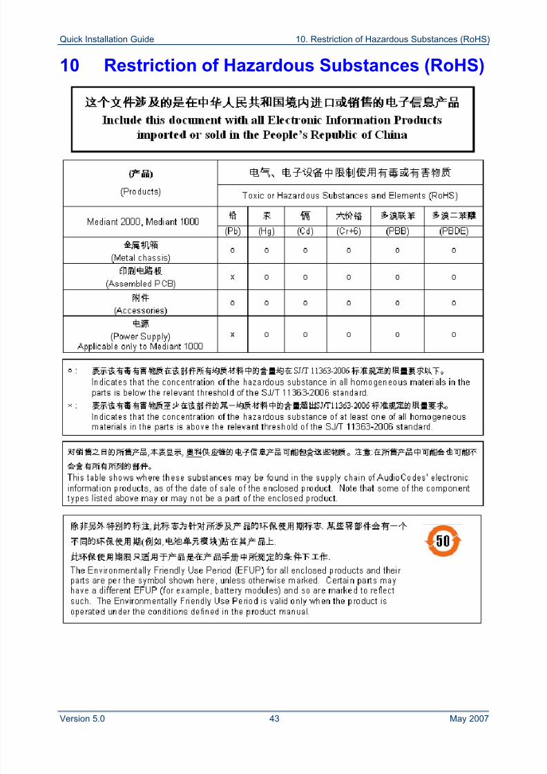
8/2/2019 LTRT-26001 Mediant 1000 and 2000 and MS OCS 2007 Quick Guide Ver 5
http://slidepdf.com/reader/full/ltrt-26001-mediant-1000-and-2000-and-ms-ocs-2007-quick-guide-ver-5 43/44
Quick Installation Guide 10. Restriction of Hazardous Substances (RoHS)
Version 5.0 43 May 2007
10 Restriction of Hazardous Substances (RoHS)
8/2/2019 LTRT-26001 Mediant 1000 and 2000 and MS OCS 2007 Quick Guide Ver 5
http://slidepdf.com/reader/full/ltrt-26001-mediant-1000-and-2000-and-ms-ocs-2007-quick-guide-ver-5 44/44
™
Mediant 1000 & Mediant 2000
Quick Installation GuideIntegration with
Integration with Microsoft ®
OfficeCommunications Server 2007
www.audiocodes.com